

Page 1

Quantum SuperLoader 3
Rail Installation and Rack
Mounting Instructions
Rail Installation and Rack Mounting Instructions 3
General Preparation for Rack Mounting................................................................4
Stationary Rack Mount Installation ........................................................................4
Installing and Removing the Optional V-Rail Kit 9
Requirements .............................................................................................................9
Accessory Pieces ......................................................................................................11
Installation in a .375 Square Hole Rack ................................................................11
Installation in a .280 Diameter Thru-Hole Rack..................................................12
Installation in a 10-32 Threaded Hole Rack.........................................................13
Chassis-Mounted Rails ...........................................................................................14
Document 81-81316-01, B01, October 2005 1
Page 2

Quantum SuperLoader 3 Rail Installation and Rack Mounting Instructions
Document 81-81316-01, B01
October 2005
Made in the USA.
Quantum Corporation provides this publication “as is” without warranty of any kind, either express or implied, including but not limited
to the implied warranties of merchantability or fitness for a particular purpose. Quantum Corporation may revise this publication from
time to time without notice.
COPYRIGHT STATEMENT
© Copyright 2005 by Quantum Corporation. All rights reserved.
Your right to copy this document is limited by copyright law. Making copies or adaptations without prior written authorization of
Quantum Corporation is prohibited by law and constitutes a punishable violation of the law.
TRADEMARK STATEMENT
Quantum, the Quantum logo, and SuperLoader are trademarks of Quantum Corporation, registered in the U.S.A. and other countries.
DLTtape and Super DLTtape are registered trademarks of Quantum Corporation. Products mentioned herein are for identification
purposes only and may be trademarks or registered trademarks of their respective companies.
2
Page 3
Quantum SuperLoader 3 Rail Installation and Rack Mounting Instructions
Document 81-81316-01 B01
October 2005
Rail Installation and Rack Mounting Instructions 0
The autoloader can be rack mounted in two ways:
• Attached directly to the cabinet rails (stationary)
• Attached to an optional V-Rail kit
Both installations are included in this manual.
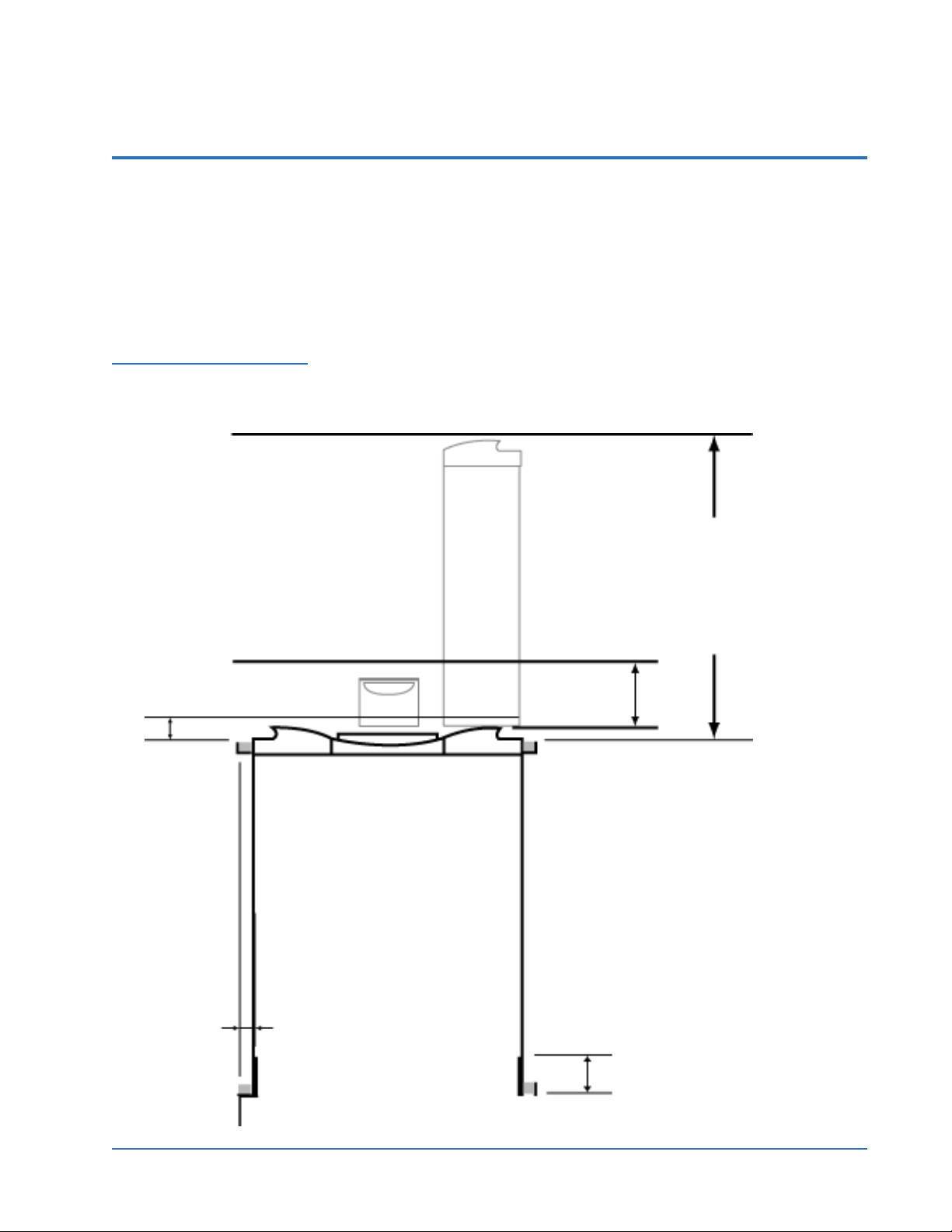
Figure 1 Clearance
Requirements for Rack
Mounting
Clearance to door inside a rack
2.0” [51 mm]
Minimum side
clearance (both
sides)
1.0” [25 mm]
Minimum clearance to load
or unload a magazine from
the system
27.0” [686 mm]
Minimum clearance to load
a tape via the mailslot
6.0” [152 mm]
FRONT
Minimum clearance
between the rear of the
SuperLoader and the
inside of the rack (using
standard mounting
brackets adjusted to their
closest setting)
REAR
3.4” [86 mm]
Rail Installation and Rack Mounting Instructions 3
Page 4

Quantum SuperLoader 3 Rail Installation and Rack Mounting Instructions
Document 81-81316-01 B01
October 2005
General Preparation for Rack Mounting
Take the following general safety steps before beginning either rack mount
0
installation.
1 Lower the cabinet feet.
2 Extend the cabinet anti-tip device, if available.
An anti-tip device may be extendable legs or similar equipment used to
stabilize the cabinet. This ant-tip equipment is to help avoid overbalancing the cabinet when installing or removing equipment.
3 Ensure that the cabinet and all rack mounted equipment have a reliable
ground connection.
4 Verify that the total current of all rack mounted components (including
the SuperLoader) will not exceed the current rating of the power
distribution unit or outlet receptacles.
5 Secure the help of at least one other person. At least two people are
required to safely install the SuperLoader into a rack cabinet.
Warning: Failure to take these safety steps may result in personal
injury or equipment damage.
Caution: Do not remove the top cover of the autoloader during the
installation process. Removing the top cover could result
in damage to the autoloader.
Stationary Rack Mount Installation
This section describes the steps for attaching the autoloader directly to the
0
rails of a rack.
1 Make sure you have the following tools and parts:
• #2 PHILLIPS
®
screwdriver
• Level
• The following autoloader accessory kit parts (see figure 2
):
• Four autoloader brackets (two long and two short to
accommodate different rack depths)
• Use the short autoloader brackets (74-60604-03) unless the
distance from the front mounting rail to the rear mounting rail is
less than 30.25 in. (76.84 cm).
• Two support brackets (74-60605-01)
• Eight 10-32 x 1/4 inch button head screws for the support
brackets (four per support bracket)
• The following parts shipped with the rack:
• Eight clip nuts
•Eight screws
4 Rail Installation and Rack Mounting Instructions
Page 5
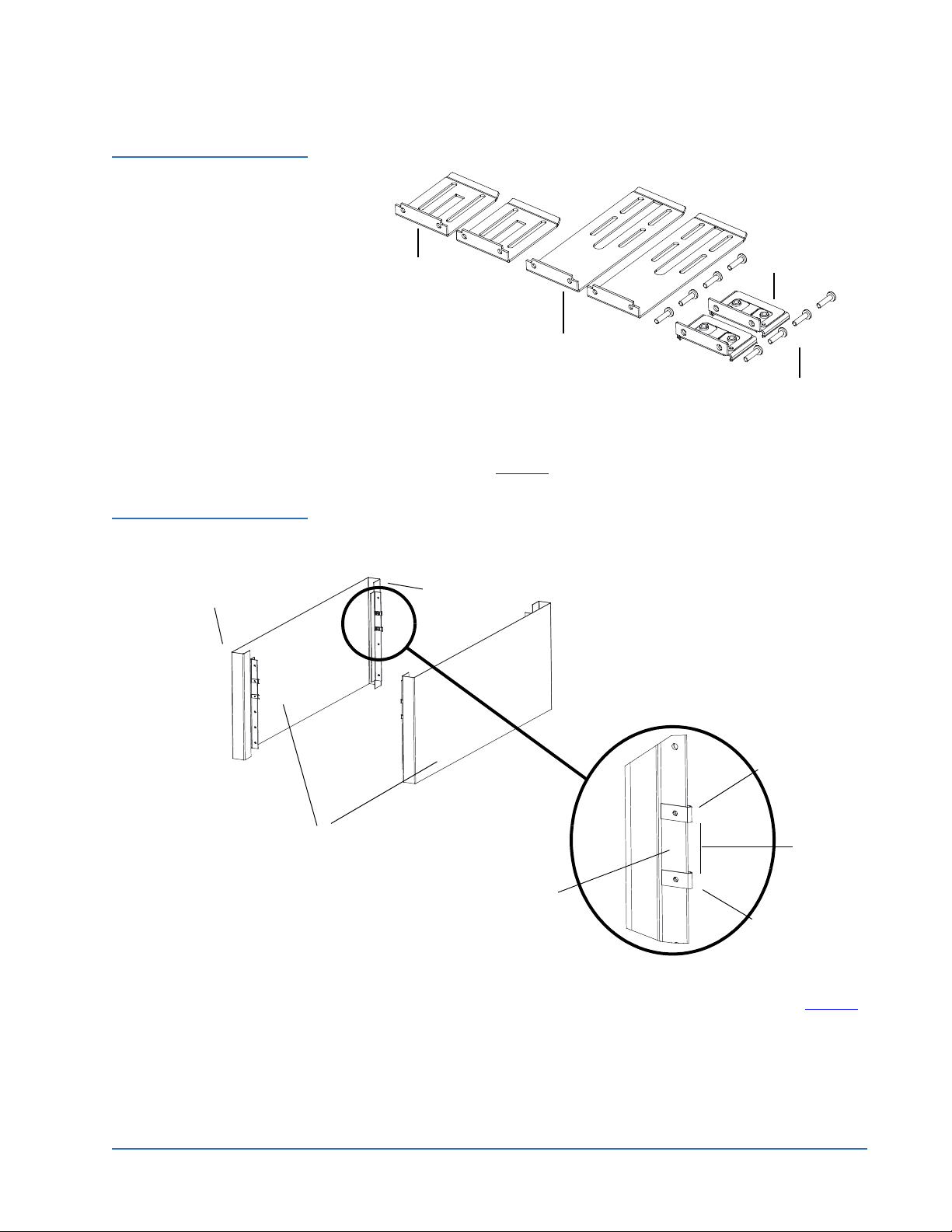
Figure 2 Required Parts
for Installation
Quantum SuperLoader 3 Rail Installation and Rack Mounting Instructions
Document 81-81316-01 B01
October 2005
Support brackets
Short autoloader
brackets (74-60604-03)
Long autoloader
brackets (74-60604-01)
Support bracket screws
(74-60605-01)
2 Install two clip nuts, 1.75 in. (44.45 mm) apart, onto each of the four rails
of the rack, making sure that you install each pair of clip nuts at exactly
the same level (see figure 3
).
Figure 3 Installing Two
Clip Nuts
Rail
Outer covers
of the rack
Rail
Clip nut
1.75 in
(44.45 mm)
Rail
Clip nut
3 Select the long or short autoloader brackets (depending on the depth of
the rack), and then attach them to the rear of the autoloader (see figure 4
Rail Installation and Rack Mounting Instructions 5
).
Page 6

Quantum SuperLoader 3 Rail Installation and Rack Mounting Instructions
Document 81-81316-01 B01
October 2005
Figure 4 Attaching
Autoloader Brackets
Autoloader
Screws (10-32 x 1/4 only)
Autoloader bracket
4 Using rack screws, attach a support bracket to the clip nuts on each rear
rail (see figure 5
.)
Note: Be sure to attach the support brackets correctly; the side of the
bracket with only two holes should be secured to the rail.
Tighten the screws just enough to hold the support brackets firmly
against the rail while still allowing the support bracket to be slightly
shifted by hand. This shifting will help facilitate the engagement of
autoloader brackets as the autoloader is installed in the rack. You will
fully tighten the screws in step 8
.
6 Rail Installation and Rack Mounting Instructions
Page 7

Figure 5 Attaching Support
Brackets
Outer cover of rack
Quantum SuperLoader 3 Rail Installation and Rack Mounting Instructions
Document 81-81316-01 B01
October 2005
Support bracket
Clip nuts
Rack
screws
Rear rail in rack
Figure 6 Sliding
Autoloader into Rack
5 With the help of a second installer, insert the autoloader into the rack so
that the autoloader brackets slide into corresponding support brackets on
the rear rails and the tabs at the front of the autoloader align flush with
the clip nuts on the front rails (see figure 6
).
Caution: Do not release the front end of the autoloader until it can
be secured to the rack.
Autoloader bracket
Support bracket
Rail Installation and Rack Mounting Instructions 7
Page 8

Quantum SuperLoader 3 Rail Installation and Rack Mounting Instructions
Document 81-81316-01 B01
October 2005
6 While the other installer holds the front end of the autoloader, secure the
autoloader in the rack by doing the following:
a Secure the front end of the autoloader to the rack using four rack
screws (two per tab) as shown in figure 7
enough to secure the autoloader to the front rails.
Figure 7 Front Alignment
Front rail
Rack
screws
Tab (one
per side)
. Tighten the screws just
Autoloader (front)
Figure 8 Connecting
Support Brackets
b Install four screws (two per side) to secure the support brackets to the
autoloader brackets (see figure 8
Screws
).
Support bracket
Autoloader
bracket
7 Verify that the autoloader is level. Adjust as needed.
8 When the autoloader is level, tighten all screws securing the autoloader to
the rack. This includes the following:
• Four screws securing the autoloader tabs to the front rails.
• Four screws securing the support brackets to the rear rails.
• Four screws securing the autoloader brackets to the support brackets.
8 Rail Installation and Rack Mounting Instructions
Page 9

Quantum SuperLoader 3 Rail Installation and Rack Mounting Instructions
Document 81-81316-01 B01
October 2005
Installing and Removing the Optional V-Rail Kit 0
The V-Rail is a set of rails, plates, and mounting hardware to use as a
stationary mounting unit allowing the autoloader to be contained within a
rack. This is not a slide rail kit, but allows some movement from the rack
cabinet for easier access or removal or the autoloader.
Requirements 0 The V-Rail can be used in many rack cabinet structures.
Front to rear rail spacing range is 25.75 – 34.50 inches (654.05 – 876.30 mm).
This range accommodates varying cabinet depths. The vertical rail thickness
is either 0.080 inch (2.03 mm) or .105 inch (7.14 mm).
Figure 9 Left Rail
Assembly
Vertical Rail Hole Types
The V-Rail can be used with the following rack hole types:
• .375 inch (9.53 mm) square through-holes
• .281 inch (7.14 mm) diameter through-holes
• 10-32 UNF-2B threaded holes
• M6–1-6H threaded holes
0
Installing and Removing the Optional V-Rail Kit 9
Page 10

Quantum SuperLoader 3 Rail Installation and Rack Mounting Instructions
Document 81-81316-01 B01
October 2005
Figure 10 Right Rail
Assembly
Figure 11 Front Mount
Features
Figure 12 Rear Mount
Features
10 Installing and Removing the Optional V-Rail Kit
Page 11

Quantum SuperLoader 3 Rail Installation and Rack Mounting Instructions
Document 81-81316-01 B01
October 2005
Accessory Pieces 0 Besides the rail parts themselves, there are two plates included with the rail
kit. These plates are used for various rack mountings. The front cover plate is
used on all rack rails. The 10-32 inside nut plate is used on the .375 inch
square rail, the .280 diameter rail, and the M6 rails.
Figure 13 Front Cover
Plate and 10-32 Nut Plates
Installation in a .375 Square Hole Rack
Front cover plate used
on all rack rails
10-32 inside nut plate used on
.375 square hole rail and .280
and M6 rails
To install the rail in a .375 square hole rack:
0
1 Identify the correct mounting holes on the vertical rail, making sure that
the selected holes are on the same level.
Installing and Removing the Optional V-Rail Kit 11
Page 12

Quantum SuperLoader 3 Rail Installation and Rack Mounting Instructions
Document 81-81316-01 B01
October 2005
Figure 14 .375 Square
Hole Rack Installation
Installation in a .280 Diameter Thru-Hole Rack
2 Mount the front cover plate to the vertical rail in the identified holes by
using 10-32 x .625 bolts in the center two holes of the plate.
3 Mount the tab of the autoloader to the upper and lower holes in the front
cover plate using 10-32 x .625 bolts.
To install the rail in a .280 diameter thru-hole rack:
0
1 Identify the correct mounting holes on the vertical rail, making sure that
the selected holes are on the same level.
12 Installing and Removing the Optional V-Rail Kit
Page 13

Figure 15 .280 Diameter
Thru-Hole Rack Installation
Quantum SuperLoader 3 Rail Installation and Rack Mounting Instructions
Document 81-81316-01 B01
October 2005
Installation in a 10-32 Threaded Hole Rack
2 Mount the front cover plate to the vertical rail in the identified holes by
using M6 (.200”) threaded bolts in the center two holes of the plate.
Note: The upper and lower tabs of the inside plate will not enter the
holes of the rack. They will deform when secured.
3 Mount the side tab of the autoloader to the upper and lower holes in the
front cover plate using M6 (.200”) threaded bolts.
To install the rail in a 10-32 threaded hole rack:
0
1 Identify the correct mounting holes on the vertical rail, making sure that
the selected holes are on the same level.
Installing and Removing the Optional V-Rail Kit 13
Page 14

Quantum SuperLoader 3 Rail Installation and Rack Mounting Instructions
Document 81-81316-01 B01
October 2005
Figure 16 10-32 Threaded
Hole Rack Installation
Chassis-Mounted Rails
2 Mount the front cover plate to the vertical rail in the identified holes by
using 10-32 x .625 bolts in the center two holes of the plate.
3 Mount the tab of the autoloader to the upper and lower holes in the front
cover plate using 10-32 x .625 bolts.
The following illustrations show various views of the chassis-mounted rail
0
system.
14 Installing and Removing the Optional V-Rail Kit
Page 15

Figure 17 Chassis Rail
Parts
Quantum SuperLoader 3 Rail Installation and Rack Mounting Instructions
Document 81-81316-01 B01
October 2005
Figure 18 Rail Installed on
Chassis
Installing and Removing the Optional V-Rail Kit 15
Page 16

Quantum SuperLoader 3 Rail Installation and Rack Mounting Instructions
Document 81-81316-01 B01
October 2005
Figure 19 Close up of
Chassis Rail
16 Installing and Removing the Optional V-Rail Kit
 Loading...