

Page 1

Manually Removing an LTO Cartridge
This document provides instructions for manually removing a data cartridge from a Certance LTO-1, LTO-2,
or LTO-3 full-height tape drive. You should only perform this procedure if you cannot remove the cartridge
by pushing the buttons on the front of the drive or by issuing commands from a host device. This should
only be necessary if you must remove a data cartridge prior to returning the drive to Certance.
CAUTION: After following these procedures, you must return the drive to Certance for repair. Do not
try to use the drive until after it has been serviced.
Before You Start
Before you manually remove a cartridge from the drive:
1. Issue all possible commands and run diagnostics.
2. Turn off all power to the drive.
3. Unplug all connectors to the drive.
4. Remove the drive from its operating environment.
5. Place the drive on a workbench with proper ESD grounding: attach a wrist strap to the bench
and the other end to your wrist.
6. Remove the top cover of the drive by removing eight screws. (You will need a 1.5-mm hex
driver.)
NOTE: Do NOT remove the front bezel or the bottom cover from the drive.
7. Inspect the drive to determine which procedure you should follow:
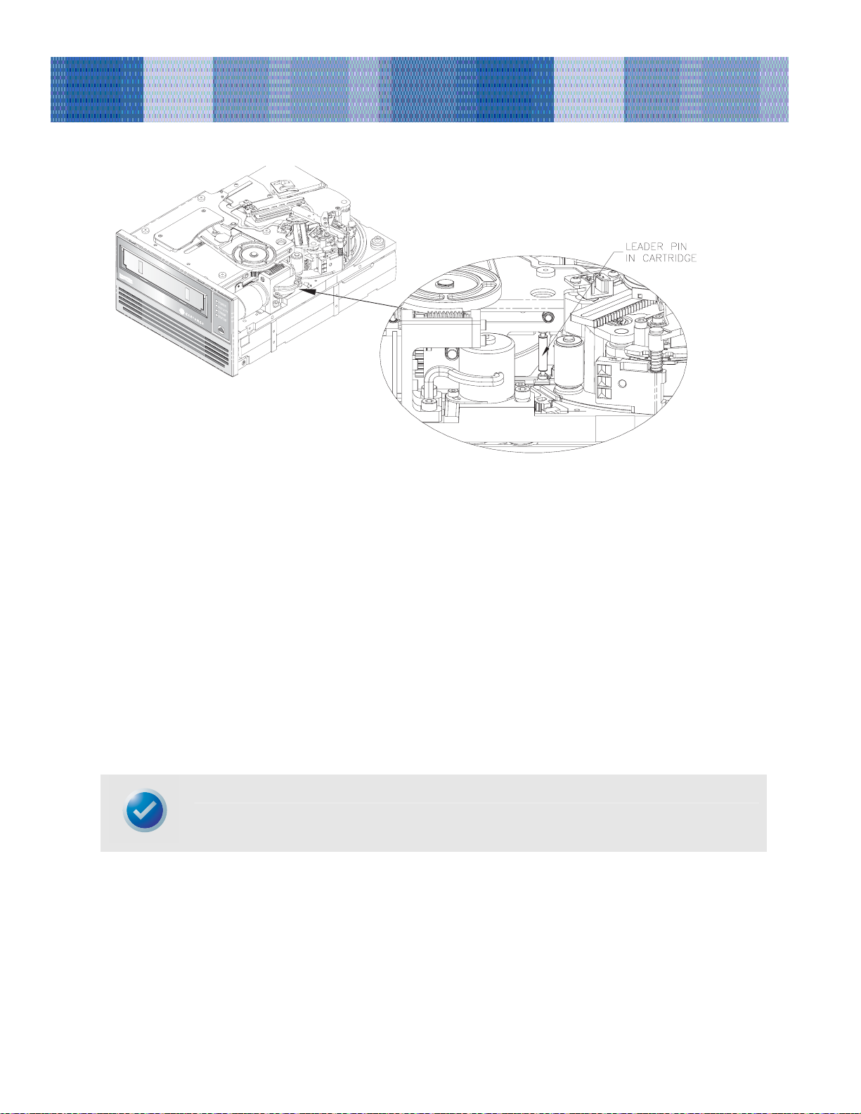
• If the cartridge is loaded and the leader pin is still in the cartridge (see Figure 1), go to “Cartridge
is Loaded and Seated” on page 2.
• If the cartridge is loaded and seated, and the tape is threaded or partially threaded on the take-up
hub, go to “Cartridge is Loaded and Seated with Tape Threaded” on page 4.
Page 2
Manually Removing an LTO Cartridge
Figure 1. Diagram of Drives with Leader Pin Inside LTO Cartridge (Tape Not Threaded on Take-up Hub)
Cartridge is Loaded and Seated
If the cartridge is loaded and seated and the leader pin is still inside the cartridge, follow these steps to
remove the cartridge. To remove the cartridge you will need a small, flat-blade screwdriver
1. Verify that the leader pin is still inside the cartridge as shown in Figure 1Error! Bookmark not
defined.. If the leader pin has been pulled out of the cartridge and is still in the tape path, follow the
steps in “ Cartridge is Loaded and Seated with Tape Threaded” on page 44.
2. Use a flat-blade screwdriver to turn the worm gear counter clockwise (to the left). Figure 2 on page 3
shows the location of the worm gear. This will gradually raise the cartridge elevator and cause the
cartridge to slide partially out of the drive.
NOTE: Do not touch any other part of the drive mechanism during this process.
2
Page 3
Manually Removing an LTO Cartridge
Figure 2. Worm Gear
3. Continue turning the worm gear until the cartridge is sticking out of the unit approximately 17 mm
(0.66”). Then carefully pull the cartridge out by hand.
4. After you have removed the cartridge, put the top cover back on the drive; then replace and tighten the
screws.
5. Return the drive to Certance.
CAUTION: Do NOT use the drive after you have removed a cartridge. The drive must be returned to
Certance for servicing.
If you have any questions about this procedure, contact Technical Support.
3
Page 4

Manually Removing an LTO Cartridge
Cartridge is Loaded and Seated with Tape Threaded
If the cartridge is loaded and seated, and the tape is entirely or partially threaded into the drive, follow
these steps. To perform these steps you will need a small, flat-blade screwdriver and a 1.5-mm hex wrench.
Figure 3 on page 4Error! Bookmark not defined. shows key components of the drive mechanism that
are referred to in the following procedure.
NOTE: Do not touch any other part of the drive mechanism except for the components specified in the
instructions. Be especially careful not to touch the tape head assembly. The MR elements in this
assembly are highly susceptible to damage from static electricity..
Worm gear
Lead screw
Load arm
Slot in
drive chassis
Take-up reel
and hub
Head assembly
Tape grabber
Figure 3. Drive Key Components
1. Be sure the head assembly is in the lowered position by turning the lead screw (see Figure 4 on
page 5Error! Bookmark not defined.) clockwise with the flat blade screwdriver. This is necessary
to allow the load arm to clear the head assembly when it is moved back toward the cartridge.
4
Page 5

Figure 4. Lead Screw (Tape Threaded on Take-up Reel)
Manually Removing an LTO Cartridge
2. Replace the drive cover to protect the gear and spooling assemblies. You do not need to replace all the
screws.
3. Turn the drive upside down.
4. Insert the 1.5-mm hex wrench through the hole in the bottom plate shown in Figure 5 on page 6Error!
Bookmark not defined.. Turn the hex wrench clockwise slowly and smoothly to rewind the tape
into the cartridge. This may take some time.
CAUTION: If you turn the hex wrench quickly or unevenly, you may create a tape loop, which could
cause tape contamination.
5
Page 6

Manually Removing an LTO Cartridge
Figure 5. Underside of Drive Showing Supply Motor Access Hole
5. When all of the tape has been spooled off of the take-up reel, turn the drive right side up.
6. Rotate the hub to align the slot in the hub with the slot on the drive chassis (see Figure 3 on
page 4Error! Bookmark not defined.).
7. Set the drive on its left side. Rotate the load arm until the tape grabber clears the hub.
CAUTION: Be especially careful not to touch the tape head assembly. The MR elements in this
assembly are highly susceptible to damage from static electricity.
8. Take up the slack tape again using the 1.5-mm hex wrench, as described in step 4.
9. Carefully push the grabber in toward the cartridge, as shown in Figure 6 on page 7.
6
Page 7

Manually Removing an LTO Cartridge
Figure 6. Tape Grabber Near the Cartridge
10. When the leader pin and the tape grabber reach the cartridge, gently push the grabber toward the
front of the cartridge. Use the grabber to push the leader pin gently into the cartridge until it seats in
place (you should hear a click).
11. Using a flat-blade screwdriver, pivot the white lower track toward the drive bezel to disengage the
leader pin.
12. After the grabber has released the leader pin, pull the loader arm out of the way.
13. Use a flat-blade screwdriver to turn the worm gear counter clockwise (to the left). Figure 7 on page
8shows the location of the worm gear. This will gradually raise the cartridge elevator and cause the
cartridge to slide partially out of the drive.
7
Page 8

Figure 7. Worm Gear
Manually Removing an LTO Cartridge
14. Continue turning the worm gear until the cartridge is sticking out of the unit approximately 17 mm
(0.66”). Then carefully pull the cartridge out by hand.
15. After removing the cartridge, put the top cover back on the drive; then replace and tighten the screws.
16. Return the drive to Certance.
If you have any questions about this procedure, contact Technical Support.
CAUTION: Do NOT use the drive after you have removed a cartridge. The drive must be returned to
Certance for servicing.
NOTE: Any tape cartridge removed using this procedure should be retensioned before it is used for
reading or writing data.
Copyright © 2004 by Certance LLC. All Rights Reserved.
May 2004
Certance and the Certance logo are trademarks of Certance LLC. Other product names are trademarks or registered trademarks of
their respective owners.
Certance reserves the right to change, without notice, product offerings or specifications. No part of this publication may be
reproduced in any form without written permission from Certance LLC.
Certance provides this document “as is,” without warranty of any kind, either expressed or implied, including, but not limited to, the
implied warranties of merchantability and fitness for a particular purpose. Certance reserves the right to change, without notification,
the specifications contained in this manual. Certance assumes no responsibility for the accuracy, completeness, sufficiency, or
usefulness of this manual, nor for any problem that might arise from the use of the information in this manual.
8
 Loading...