

Page 1
Page 2

Copyright
Copyright © 2004 by Quantum Corporation. All rights res erved.
Document Origination: Boulder, Colorado, USA.
Trademarks
Quantum, the Quantum logo, and the DLTtape logo are trademarks of Quantum Corporation, regi stered in the
U.S.A. and other countries. DLTtape, DLTSage, Value DLTtape, and Super DLTtape are trademarks of Quantum
Corporation.
Other company and produc t names used in this document are trade mar ks, registered trademarks, or service
marks of their respective owners.
Legal Disclaimers
The inform ation contained in this docum ent is the exclusive property of Quantum Corp oration. Quantum retains
its copyri ght on the information contained herein in al l cases and situations of usage, including derivative works.
The possess or agrees to safe gua rd thi s infor mat ion and to m ain tain it in con fide nce and not r e-publi s h it in whole
or in part without Quantum’s prior written consent.
Quantum reserves the right to make changes and improvements to its products, without incurring any obligation
to incorporate such cha nges or improvements in unit s previously sold or shipped.
Contact Information
You can request Quant um publ ications from your Quantum Sales Re presentative or order them direc tly from
Quantum.
Telephone numbers and street addres s es change frequently; for the latest, up-to-date contact information, visit
www.quantum.com
The Contact Us section of the web site lists telephone numbers, street addresses, time zones, and other pertine nt
facts.
ii May 2004 001596-01 Rev A07
Page 3

Revision History
The following table lists all revision s made to this document.
Document Rele ase Date Summary of Changes
001596-01 Rev 01 February 2, 2001 Initial preliminary re lease
001596-0 1 Rev 02 February 6, 2001 Updated LED sequ ence
001596-0 1 Rev 03 February 16, 2001 Updated external SCSI ID setti ng
001596-0 1 Rev 04 April 5, 2001 Updated logo and product name
001596-01 Rev 05 May 4, 2001 Edits per Jeff Faucet
001596-01 Rev 06 July 20, 2001 Updated internal unit mounting to include screw length
001596-01 Rev A07 May 12, 2004 Converted to FrameMaker, using the Quantum template and
style guide per ECO C009631
001596-01 Rev A07 May 2004 iii
Page 4

Notes
iv May 2004 001596-01 Rev A07
Page 5

Ta ble of Contents
1 Introduction . . . . . . . . . . . . . . . . . . . . . . . . . . . . . . . . . . . . . . . 1-1
Purpose and Scope. . . . . . . . . . . . . . . . . . . . . . . . . . . . . . . . . . . . . . . . . . . . . . . . . . . . . . . . . . . . . . . 1-1
Related Documents . . . . . . . . . . . . . . . . . . . . . . . . . . . . . . . . . . . . . . . . . . . . . . . . . . . . . . . . . . . . . . 1-1
Structure of this Manual . . . . . . . . . . . . . . . . . . . . . . . . . . . . . . . . . . . . . . . . . . . . . . . . . . . . . . . . . . 1-1
Conventions Used in this Manual . . . . . . . . . . . . . . . . . . . . . . . . . . . . . . . . . . . . . . . . . . . . . . . . . . . 1-2
For More Information . . . . . . . . . . . . . . . . . . . . . . . . . . . . . . . . . . . . . . . . . . . . . . . . . . . . . . . . . . . . 1- 2
Reader Comments . . . . . . . . . . . . . . . . . . . . . . . . . . . . . . . . . . . . . . . . . . . . . . . . . . . . . . . . . . . . . . . 1 -2
2 Product Information . . . . . . . . . . . . . . . . . . . . . . . . . . . . . . . . . 2-1
DLT VS80 Tape Drive Overview . . . . . . . . . . . . . . . . . . . . . . . . . . . . . . . . . . . . . . . . . . . . . . . . . . . 2-1
DLT VS80 Tape Drive Features . . . . . . . . . . . . . . . . . . . . . . . . . . . . . . . . . . . . . . . . . . . . . . . . . . . . 2-1
Data Transfer Rate . . . . . . . . . . . . . . . . . . . . . . . . . . . . . . . . . . . . . . . . . . . . . . . . . . . . . . . . . . . 2-1
Capacity . . . . . . . . . . . . . . . . . . . . . . . . . . . . . . . . . . . . . . . . . . . . . . . . . . . . . . . . . . . . . . . . . . . 2-2
Data Compression . . . . . . . . . . . . . . . . . . . . . . . . . . . . . . . . . . . . . . . . . . . . . . . . . . . . . . . . . . . . 2-2
Media . . . . . . . . . . . . . . . . . . . . . . . . . . . . . . . . . . . . . . . . . . . . . . . . . . . . . . . . . . . . . . . . . . . . . 2-2
Compatibility . . . . . . . . . . . . . . . . . . . . . . . . . . . . . . . . . . . . . . . . . . . . . . . . . . . . . . . . . . . . . . . 2-2
Firmware Update Capability. . . . . . . . . . . . . . . . . . . . . . . . . . . . . . . . . . . . . . . . . . . . . . . . . . . . 2-2
Embedded Diagnostics . . . . . . . . . . . . . . . . . . . . . . . . . . . . . . . . . . . . . . . . . . . . . . . . . . . . . . . . 2-2
3 DLT VS80 Installation . . . . . . . . . . . . . . . . . . . . . . . . . . . . . . . . 3-1
Preparing to Install Your Tape Drive. . . . . . . . . . . . . . . . . . . . . . . . . . . . . . . . . . . . . . . . . . . . . . . . . 3-1
SCSI Requirements. . . . . . . . . . . . . . . . . . . . . . . . . . . . . . . . . . . . . . . . . . . . . . . . . . . . . . . . . . . 3-1
Before You Begin . . . . . . . . . . . . . . . . . . . . . . . . . . . . . . . . . . . . . . . . . . . . . . . . . . . . . . . . . . . . 3-2
Installing Your Tabletop Tape Drive . . . . . . . . . . . . . . . . . . . . . . . . . . . . . . . . . . . . . . . . . . . . . . . . . 3-2
Unpackin g Your Tabletop Tape Drive and Selectin g a Lo cation . . . . . . . . . . . . . . . . . . . . . . . . 3-2
Unpacking Your Tabletop Tape Drive . . . . . . . . . . . . . . . . . . . . . . . . . . . . . . . . . . . . . . . . . 3-2
Selecting a Location for Your Tabletop Tape Drive . . . . . . . . . . . . . . . . . . . . . . . . . . . . . . 3-3
001596-01 Rev A07 May 2004 v
Page 6

T able of Contents
Installing Your Internal Tape Drive. . . . . . . . . . . . . . . . . . . . . . . . . . . . . . . . . . . . . . . . . . . . . . . . . 3-10
Testing Your T ape Drive . . . . . . . . . . . . . . . . . . . . . . . . . . . . . . . . . . . . . . . . . . . . . . . . . . . . . . . . . 3-18
Trouble shooting Your Tape Drive. . . . . . . . . . . . . . . . . . . . . . . . . . . . . . . . . . . . . . . . . . . . . . . . . . 3-19
Setting the SCSI ID. . . . . . . . . . . . . . . . . . . . . . . . . . . . . . . . . . . . . . . . . . . . . . . . . . . . . . . . . . . 3-4
Connecting the Cables . . . . . . . . . . . . . . . . . . . . . . . . . . . . . . . . . . . . . . . . . . . . . . . . . . . . . . . . 3-5
Terminating Your Tabletop Tape Drive. . . . . . . . . . . . . . . . . . . . . . . . . . . . . . . . . . . . . . . . 3-8
Powering the Terminator . . . . . . . . . . . . . . . . . . . . . . . . . . . . . . . . . . . . . . . . . . . . . . . . . . . 3-8
Completing the Installation. . . . . . . . . . . . . . . . . . . . . . . . . . . . . . . . . . . . . . . . . . . . . . . . . . . . . 3-9
Unpacking Your Internal Tape Drive . . . . . . . . . . . . . . . . . . . . . . . . . . . . . . . . . . . . . . . . . . . . 3-10
Configuring Your Internal Tape Drive . . . . . . . . . . . . . . . . . . . . . . . . . . . . . . . . . . . . . . . . . . . 3-11
Setting the SCSI ID . . . . . . . . . . . . . . . . . . . . . . . . . . . . . . . . . . . . . . . . . . . . . . . . . . . . . . 3-11
Terminating Your Internal Tape Drive. . . . . . . . . . . . . . . . . . . . . . . . . . . . . . . . . . . . . . . . 3-12
Installing Your Internal Tape Drive . . . . . . . . . . . . . . . . . . . . . . . . . . . . . . . . . . . . . . . . . . . . . 3-13
General T roubleshooting Guidelines . . . . . . . . . . . . . . . . . . . . . . . . . . . . . . . . . . . . . . . . . . . . 3-19
Trouble shooting the Tape Drive . . . . . . . . . . . . . . . . . . . . . . . . . . . . . . . . . . . . . . . . . . . . . . . . 3-19
4 DLT VS80 Use. . . . . . . . . . . . . . . . . . . . . . . . . . . . . . . . . . . . . . . 4-1
Front Panel Controls and Indicators . . . . . . . . . . . . . . . . . . . . . . . . . . . . . . . . . . . . . . . . . . . . . . . . . 4-1
Indicator Activity During Power-On Self-Test (POST) . . . . . . . . . . . . . . . . . . . . . . . . . . . . . . . 4-2
Indicator Activity During Tape Drive Operation . . . . . . . . . . . . . . . . . . . . . . . . . . . . . . . . . . . . 4-2
Data Cartridge Use and Care. . . . . . . . . . . . . . . . . . . . . . . . . . . . . . . . . . . . . . . . . . . . . . . . . . . . . . . 4-4
Loading a Data Cartridge . . . . . . . . . . . . . . . . . . . . . . . . . . . . . . . . . . . . . . . . . . . . . . . . . . . . . . 4-4
Unloading a Data Cartridge . . . . . . . . . . . . . . . . . . . . . . . . . . . . . . . . . . . . . . . . . . . . . . . . . . . . 4-5
Write-Protecting Data Cartridges . . . . . . . . . . . . . . . . . . . . . . . . . . . . . . . . . . . . . . . . . . . . . . . . 4-6
Caring for Your Data Cartridges . . . . . . . . . . . . . . . . . . . . . . . . . . . . . . . . . . . . . . . . . . . . . . . . . 4- 7
Using the Cleaning Cartridge . . . . . . . . . . . . . . . . . . . . . . . . . . . . . . . . . . . . . . . . . . . . . . . . . . . 4-8
5 DLT VS80 Firmware . . . . . . . . . . . . . . . . . . . . . . . . . . . . . . . . . . 5-1
Updating Tape Drive Firmware—Overview . . . . . . . . . . . . . . . . . . . . . . . . . . . . . . . . . . . . . . . . . . . 5-1
Creating a Firmware Update Data Cartridge. . . . . . . . . . . . . . . . . . . . . . . . . . . . . . . . . . . . . . . . . . . 5-2
Updating the Firmware . . . . . . . . . . . . . . . . . . . . . . . . . . . . . . . . . . . . . . . . . . . . . . . . . . . . . . . . . . . 5-2
Updating the Firmware . . . . . . . . . . . . . . . . . . . . . . . . . . . . . . . . . . . . . . . . . . . . . . . . . . . . . . . . 5-2
Trouble shooting the Firmware Upgrade. . . . . . . . . . . . . . . . . . . . . . . . . . . . . . . . . . . . . . . . . . . 5-4
vi Ma y 20 04 001596-01 Re v A07
Page 7

List of Fig ures
3 DLT VS80 Installation . . . . . . . . . . . . . . . . . . . . . . . . . . . . . . . . 3-1
Figure 3-1. Tabletop Tape Drive Rear Panel Layout. . . . . . . . . . . . . . . . . . . . . . . . . . . . . . . . . . . . . 3-4
Figure 3-2. SCSI ID Selector Switch. . . . . . . . . . . . . . . . . . . . . . . . . . . . . . . . . . . . . . . . . . . . . . . . . 3-5
Figure 3-3. Tape Drive SCSI and Power Cable Connections . . . . . . . . . . . . . . . . . . . . . . . . . . . . . . 3-6
Figure 3-4. Workstation SCSI Cable Connections . . . . . . . . . . . . . . . . . . . . . . . . . . . . . . . . . . . . . . 3-7
Figure 3-5 . Back Panel Connections , Tabletop Tape Drive. . . . . . . . . . . . . . . . . . . . . . . . . . . . . . . . 3-8
Figure 3-6 . Back Panel Connections , Internal Tape Drive . . . . . . . . . . . . . . . . . . . . . . . . . . . . . . . 3-11
Figure 3-7. Terminator Installation . . . . . . . . . . . . . . . . . . . . . . . . . . . . . . . . . . . . . . . . . . . . . . . . . 3-12
Figure 3-8. SCSI Cable with Built-in Terminator . . . . . . . . . . . . . . . . . . . . . . . . . . . . . . . . . . . . . . 3-13
Figure 3-9. Remove the Workstation Cover (example shown) . . . . . . . . . . . . . . . . . . . . . . . . . . . . 3-14
Figure 3-10. Tape Drive Installation in an Open Drive Bay . . . . . . . . . . . . . . . . . . . . . . . . . . . . . . 3-15
Figure 3-11. SCSI and Power Cable Location (Internal Tape Drive) . . . . . . . . . . . . . . . . . . . . . . . 3-16
Figure 3-1 2 . Securing t h e Internal Tape Drive in the Ins tallatio n Bay . . . . . . . . . . . . . . . . . . . . . . 3-17
4 DLT VS80 Use. . . . . . . . . . . . . . . . . . . . . . . . . . . . . . . . . . . . . . . 4-1
Figure 4-1. Tabletop Tape Drive Front Panel Layout . . . . . . . . . . . . . . . . . . . . . . . . . . . . . . . . . . . . 4-1
Figure 4 -2 . L o a d ing a DLTtape IV D at a Cartridg e . . . . . . . . . . . . . . . . . . . . . . . . . . . . . . . . . . . . . . 4-4
Figure 4-3. Unloading a DLTtape IV Data Cartridge . . . . . . . . . . . . . . . . . . . . . . . . . . . . . . . . . . . . 4-5
Figure 4-4. Data Cartridge Write-Protect Switch . . . . . . . . . . . . . . . . . . . . . . . . . . . . . . . . . . . . . . . 4-6
Figure 4-5. DLT Cleaning Cartridge . . . . . . . . . . . . . . . . . . . . . . . . . . . . . . . . . . . . . . . . . . . . . . . . . 4-8
001596-01 Rev A07 May 2004 vii
Page 8

List of Figures
Notes
viii May 2004 001596-01 Rev A07
Page 9

List of Tables
3 DLT VS80 Installation . . . . . . . . . . . . . . . . . . . . . . . . . . . . . . . . 3-1
Table 3-1. Selecting the SCSI ID. . . . . . . . . . . . . . . . . . . . . . . . . . . . . . . . . . . . . . . . . . . . . . . . . . . 3-11
T able 3-2. Understanding Errors Indicated by Front Panel LEDs. . . . . . . . . . . . . . . . . . . . . . . . . . 3-20
4 DLT VS80 Use. . . . . . . . . . . . . . . . . . . . . . . . . . . . . . . . . . . . . . . 4-1
Table 4-1. Tape Drive Status and Indicator Activity . . . . . . . . . . . . . . . . . . . . . . . . . . . . . . . . . . . . . 4-2
Table 4-2. Indicator Activity . . . . . . . . . . . . . . . . . . . . . . . . . . . . . . . . . . . . . . . . . . . . . . . . . . . . . . . 4-3
5 DLT VS80 Firmware . . . . . . . . . . . . . . . . . . . . . . . . . . . . . . . . . . 5-1
T able 5-1. Firmware Upgrade Troubleshooting . . . . . . . . . . . . . . . . . . . . . . . . . . . . . . . . . . . . . . . . 5-4
001596-01 Rev A07 May 2004 ix
Page 10

List of Tables
Notes
x May 2004 001596-01 Rev A07
Page 11

1.1 Purpose and Scope
This Install ation and Operations Guide is a comprehensive source of information about the DLT VS80
tape drive (interna l and table top).
This manual provides all the information you need to install and use your internal tape drive or
tabletop tape drive.
CHAPT ER 1
Chapter 1Introduction
1.2 Related Documents
DLT VS80 Tape Drive Product Specificati on (001597-01)
DLT1/VS80 SCSI Interface Guide (000825-01)
1.3 Structure of this Manual
• Chapter 1, “Introduction,” is the chapter you are currently reading.
• C hapter 2, “Product Information,” provides a general over view of the product.
• C hapter 3, “DLT VS80 Installation,” explains how to configure and install your tabletop or
internal tape drive.
• C hapter 4, “DLT VS80 Use,” explains how to use your tape drive.
• C hapter 5, “DLT VS80 Firmware,” explains how to update your tape drive’s firmware.
001596-01 Rev A07 May 2004 1-1
Page 12

Chapter 1: Introduction
1.4 Conventions Used in this Manual
This manual uses the following conve ntions:
NOTE: Notes provide supplemental information.
C
AUTION Cautions provide information you mus t know to avoid
damaging the tape drive or losing data.
1.5 For More Information
The web site www.quantum.com includes valuable information about all Quantum products; or for
personalized inf ormation about Quantum’s reliable data protection produc ts, call 1-800-624-5545 in
the U.S.A. and Canada.
1.6 Reader Comments
Quantum is committed to providing the best products and service. We encourage your comments,
suggestions, and corrections for this manual. Please send all comments to this address:
Quantum Technical Publications
4001 Discovery Dr.
Suite 120
Boulder, Colorado USA 80303
1-2 May 2004 001596-01 Rev A07
Page 13

Chapter 2Product Information
This chapter introduces the DLT VS80 tape drive and provides a general overview of the product.
2.1 DLT VS80 Tape Drive Overview
Your Quantum DLT VS80 tape drive is a value-priced, high-relia bility , high-capacity linear strea ming
data cartridge tape dr ive designed for use on entry- to mid-range computing platforms. With a
combination of data compres sion and compaction, your DLT VS80 tape drive offers a data cart ridge
capacity of 80 gigabytes (GB) (assuming a 2:1 compression ratio), and a sustained user data transfer
rate of 6 megabytes (MB) per second (assuming a 2:1 compression ratio).
CHAPT ER 2
The DLT VS80 tape drive is a 5¼-inch, half-heigh t form- factor de vice t hat uses ½-in ch tape. Its de sign
includes a dual channel read /write head, Lempel-Ziv (DLZ) high-ef ficiency data compression, and a
tape-mark directory to achieve fast data throughput and data access times.
2.2 DLT VS80 Tape Drive Features
2.2.1 Data Transfer Rate
The tape drive’s native (uncompressed) dat a transfer rate is 3.0 MB per second. With 2:1 data
compression, the data transfer rate increases to as much as 6.0 MB per second.
001596-01 Rev A07 May 2004 2-1
Page 14

Chapter 2: Product Information
2.2.2 Capacity
The tape drive use s DLTtape™ IV data cartridges, which of fer 40 GB of nat ive data s torag e or up to 80
GB of compressed data storage.
The capacity you realize in practice depends on the data set.
2.2.3 Data Compression
The tape drive includes a data compression feature that helps it store data efficiently. A read/write
buffer of up to 2 MB provi des working spa ce for t he compressio n feature, allowing you to get the most
out of the availabl e med ia s pa ce.
2.2.4 Media
The DLTtape IV media is designed to endure 1,000,000 passes and has a shelf life of 30 years,
providing superior media durability and data reliability.
2.2.5 Compatibility
The tape drive is read-compatible with the DLT4000 tape drive format using DLTtape IV data
cartridges.
For current informati on on opera ting system, application, and tape driv er compat ibility , visit
www.quantum.com
2.2.6 Firmware Update Capability
The DLT VS80 includes Flash EEPROM technology so you can make on–site firm ware updates from
tape or the Small Computer System Interf ace (SCSI) bus.
2.2.7 Embedded Diagnostics
The DLT VS80 has embedded diagnostic softwar e that indicates diagnostic results and tape drive
operating status , and it tells you when you need to clean the tape drive. The tape drive also has
embedded error logging to help you dia gnose any reported problems.
2-2 May 2004 001596-01 Rev A07
Page 15

Chapter 3DLT VS80 Installation
This chapter expla ins how to c onfigur e and insta ll your table top or int ernal ta pe drive . Foll ow the steps
and instructions prese nted in this chapter to install and configure your tape drive.
3.1 Preparing to Install Your Tape Drive
This section helps you prepare to install your tabletop tape drive or internal tape drive.
CHAPT ER 3
3.1.1 SCSI Requirements
Your DLT VS80 tape drive (tabletop and inte rnal) incorporate s a wide Ultra SCSI -2 SCSI bus, but you
can also attach it to a single-ended (SE) or low-voltage differential (LVD) SCSI bus.
Make sure your SCSI host bus adapter or controller supports these configurations. I f you connect the
tape drive to an SE bus, or if there are SE devices attached to the same SCSI bus, the tape drive’s
performance is limite d to the maximum data transfer speed and maximum cable lengths of the SE bus
(usually 40 MB/ s).
NOTE: The DLT VS80 is not compatible with a standard differential or high-
voltage diff erential (HVD) SCSI bus.
001596-01 Rev A07 May 2004 3-1
Page 16

Chapter 3: DLT VS80 Instal la tio n
3.1.2 Before You Begin
Installing your DLT VS80 tabletop tape drive requires no special tools. You will need a ballpoint pen
to change the SCSI ID switch on the rear panel of the tape drive.
If you are installing a DLT VS80 internal tape drive, refer to “Insta lling Your Internal Tape Drive” on
page 3-10 for instructions. Installing your DLT VS80 internal tape drive requires the tools neede d to
install an internal ta pe drive in the computer you have chosen to house the tape drive (for example, a
screwdriver and some ESD protection).
3.2 Installing Your Tabletop Tape Drive
This section contains step-by-step instructions for installing your DLT VS80 tabletop tape drive. Be
sure to read through this entir e section before beginning the installat ion.
3.2.1 Unpacking Your Tabletop Tape Drive and Selecting a Location
Before you begin, clear a desk or table so that you can unpack your tabletop tape drive. You also need
to select a location near the server or workstation that is to host your tape drive.
NOTE: If the room in which you are working diff ers f rom the temperature at
which the tabletop tape drive was shipped or stored by 30 ºF (15 ºC) or
more, let the tape drive acclimate to the surrounding environment for at
least 12 hours before openin g the shipp ing carton.
Unpacking Your Tabletop Tape Drive
The first step is to unpack and inspect your tabletop tape drive for shipping damage, following these
steps:
1. Inspect the shipping box for damage. I f you notice any damage, report it to the shipping company
immediately.
2. Open the shipping box and remove the accessories package. Open the accessories package so that
the accessories are handy during installation.
3-2 May 2004 001596-01 Rev A07
Page 17

DLT VS80 Tape Drive Installation and Operations Guide
3. With the tape drive still in the shipping box, reach under and aro und the tape drive, carefully lift it
out of the shipping box, an d place it on the work surfac e, top facing up. Do not stand the tape dri ve
on either end.
4. Carefully remove the tape drive from the protective bag.
NOTE: Save the packing materials in case you need to move or ship your tape
drive in the future. You must ship your tabletop tape drive in the original
or equivalent packing materia ls to preserve your warranty.
Selecting a Location for Your Tabletop Tape Drive
Select a location for your tape drive that is flat, sturdy, level, and close to the server or workstation. A
desk or tabletop surfac e is most suita ble. Regardless of the location you choose, make sure the
environment is free from dust, cigarette smoke, and excessive temperature and humidity. See the DLT
VS80 Tape Drive Product Specification for acceptable operating temperature and humidity limits.
Be sure to follow these addition al guidelines when selecting a location for your tape drive:
• Allow at least 6 inches (15.2 cm) behind the tape drive for proper cooling.
• A void locations near pr inters or photocopy machine s, both of which produce paper fiber and other
types of dust and airborne contaminants.
• Do not place your tape drive on the floor.
AUTION Avoid locations near generators, electric motors, audio
C
speakers, or other sources of magnetic fields. Magnetic fields
can adversely affe ct your tape drive and data cartridges.
001596-01 Rev A07 May 2004 3-3
Page 18

Chapter 3: DLT VS80 Instal la tio n
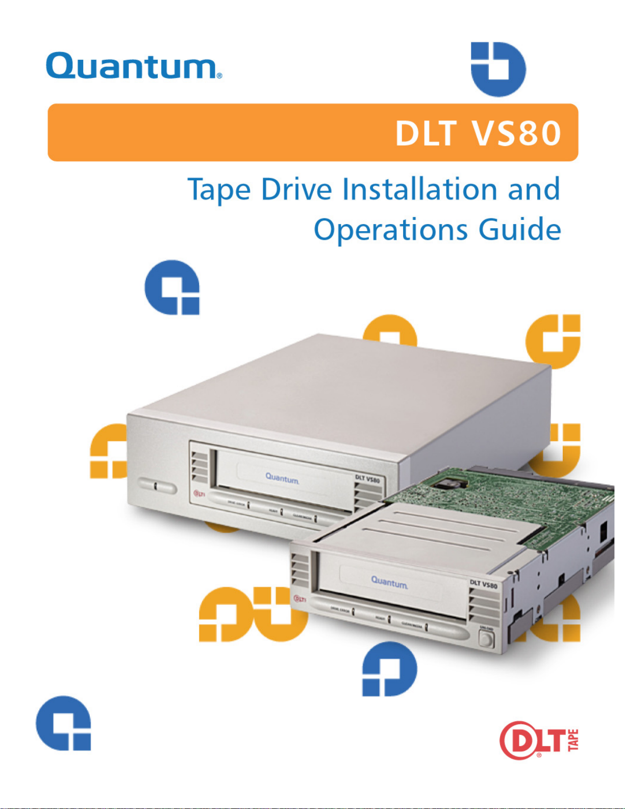
68-pin high-density SCSI connectors
SCSI ID switch
5
3.2.2 Setting the SCSI ID
All SCSI devices attached to the server or workstation must have a unique SCSI ID. Check the SCSI
IDs on all other devic es on the selec ted server or workst ation, including t he SCSI host bus adap ter , and
select an unused SCSI ID for your tape drive. The fac tory default SCSI ID for this tape drive is 5, as
shown in Figure 3-1. If the tape drive’s f actory default SCSI ID is not already in use by another device
on the same SCSI bus, you do not need to change the SCSI ID.
Figu r e 3-1. Tabletop Tape Drive Rear Panel Layout
On
Off
Power
switch
Power
cable connector
NOTE: If the tabletop tape driv e is atta ched to a narrow SCSI bus, only IDs 0
through 7 are valid. If it is a wide SCSI bus, then you can use IDs 0
through 15.
3-4 May 2004 001596-01 Rev A07
Page 19
DLT VS80 Tape Drive Installation and Operations Guide
To set the SCSI ID on the tabletop tape drive, use a small screwdriver or ballpoint pen to press the
button above the S CSI ID displa y t o select the next lo wer S CSI ID. Pre ss the b utton below the SCSI I D
display to select the next higher SCSI ID. Each time you press one of these buttons, the SCSI ID
decreases or increases by one. Press the appropriate button until the desired SCSI ID appears on the
switch display.
Press here to decrease
SCSI ID
Press here to increase
SCSI ID
Figu r e 3-2. SCSI ID Sele ctor Swi tch
NOTE: If the tape drive is powered on when you change the SCSI ID, you must
power the tape drive off an d on again for the new SCSI ID to take effect.
3.2.3 Connecting the Cables
Follow these steps to connect the SCSI and power cables to your tape drive:
NOTE: If the selected server or workstation does not already have an installed
SCSI host bus adapter, you will need to install one. For more information
on SCSI host bus adapter requirement s, see “SCSI Requirements” on
page 3-1.
1. Shut down the operating system and power down the serve r or workstation.
2. Power off all attache d peripheral devices, such as printers and other SCSI devices.
AUTION Do not go to step 3 until you have completed steps 1 and 2.
C
Failure to follow these instr uctions may result in damage to
your tape drive or other devices.
3. Select a SCSI cable with an open 68-pin, high-density connector.
001596-01 Rev A07 May 2004 3-5
Page 20

Chapter 3: DLT VS80 Instal la tio n
4. Connect one end of the SCSI c able to one of the connectors on the rear panel of your tape drive , as
shown in Figure 3-3. Either SCSI connector works equally well.
To next
device
To SCSI
host bus adapter
Figu r e 3-3. Tape Drive SCSI and Power Cable Connections
NOTE: Figure 3-3 does not show a terminator because none of the three tape
drives in the illustr ation are at the end of the SCSI bus.
3-6 May 2004 001596-01 Rev A07
Page 21

DLT VS80 Tape Drive Installation and Operations Guide
5. Connect the ot her end of the SCSI cable to the connector on your SCSI host bus adapter, as shown
in Figure 3-4 or to the connector on the previous SCSI device on the SCSI bus.
Host bus adapter
SCSI cable
Figu r e 3-4. Workstation SCSI Cable Connections
NOTE: If the SCSI cable does not f it the connector on the SCSI host bus adapter,
you either have an incompatible SCSI host bus adapter or you need to
purchase a cabl e adap t er. Contact Quan t um Co rp oration or your SCS I
host bus adapter manufacturer for information.
001596-01 Rev A07 May 2004 3-7
Page 22

Chapter 3: DLT VS80 Instal la tio n
r
Terminating Your Tabletop Tape Drive
You must terminate the tape drive if it is the last physical device on the SCSI bus (at the end of the
SCSI chain). If another SCSI device is the last device on the SCSI bus, confirm that it is properly
terminated and do not terminate your tape drive.
NOTE: Regardless of which device termin ates the SCSI bus, it must have power
applied and be powered on for proper termination to occur.
T o terminate your tape drive, press the terminator firmly into either of the two SCSI connectors on the
rear panel of the tape drive. Secure it by tightening the screws until snug. See Figure 3-5 for more
information.
Terminator
(or cable to next
SCSI device)
Powe
SCSI cable
(to computer or
previous SCSI
device)
cord
Figu r e 3-5. Back Panel Connections, Tabletop Tape Drive
Powering the Terminator
At least one device on the SCSI bus must supply termina tor power (TERMPWR). The factory default
for the ta pe drive is for TER MPWR to be enabled. Only an authorized servic e provider can disabl e the
tape drive TERMPWR setting.
NOTE: It is acceptable for more than one device on the SCSI bus to provide
TERMPWR
3-8 May 2004 001596-01 Rev A07
Page 23

3.2.4 Completing the Installation
1. Secure all the SCSI cable connectors by tightening their screws until snug.
2. Make sure the power switch on the rear panel of the table top tape drive is in the OFF position. S ee
Figure 3-1 for reference.
3. Attach the fem ale co nn ect or on t he power cable to the powe r connector on the rear pa nel of the
tape drive.
4. Plug in the power cable to a nearby power outlet .
5. Attach the powe r cab l es to the h ost se rv er or wor kst at io n and all att ached d evi ces.
6. Power on the tabletop tape drive and any other devi ces you powered off earlier.
7. Power on the host server or workstation a nd allow its operating system to start.
8. Check your tape drive to make sure it is working properly. S ee “Testing Your Tape Drive” on
page 3-18 to learn about the tabletop tape drive’s POST and initialization featur es.
DLT VS80 Tape Drive Installation and Operations Guide
001596-01 Rev A07 May 2004 3-9
Page 24

Chapter 3: DLT VS80 Instal la tio n
3.3 Installing Your Internal Tape Drive
This section contains step-by-step instructions for installing your DLT VS80 internal tape drive. Be
sure to read through the entire section before beginning the installation.
3.3.1 Unpacking Your Internal Tape Drive
First, clear a desk or table so that you can unpack your tape drive.
NOTE: If the room in which you are working diff ers f rom the temperature in
which the tape drive was shipped or stor ed by 30 ºF (15 ºC) or more, let
the tape drive acclimat e to the surrounding environment for at least
12 hours before opening the shipping carton.
The first step is to unpack and in spect the tape drive for shipping damage. To do a thorough job, follow
these steps:
1. Inspect the shipping box for damage. I f you notice any damage, report it to the shipping company
immediately.
2. Open the shipping box and remove the accessories.
3. With the tape drive still in the shipping box, reach under and aro und the tape drive, carefully lift it
out of the shipping box, an d place it on the work surfac e, top facing up. Do not stand the tape dri ve
on either end.
4. Carefully remove the tape drive from the protective bag.
NOTE: Save the packing materials in case you need to move or ship your tape
drive in the future. You must ship your tape drive in the original or
equivalent packing materials to preserve your warranty.
If there is no damage to t he tape dr ive, sele ct a serve r or workst ation to ho st your ta pe dri ve, then mov e
on to the following installa tion steps.
3-10 May 2004 001596-01 Rev A07
Page 25

DLT VS80 Tape Drive Installation and Operations Guide
68-pin SCSI connector
SCSI ID jumpers
3.3.2 Configuring Your Internal Tape Drive
The following sections explain how to configure your internal tape drive.
Setting the SCSI ID
All SCSI devices that are attached to the server or workstation must have a unique SCSI ID. Check the
SCSI IDs on all other devices on the selected server or workstation, including the SCSI host bus
adapter , and select an unused SCSI ID for your tape drive. The factory defaul t SCSI ID is 5drive’s
factory default SCSI ID is not being used, you do not need to change the SCSI ID.
NOTE: If the tape drive is a ttached to a narrow SCSI bus, you can onl y use IDs 0
through 7. If it is a wide SCSI bus, then you can use IDs 0 through 15.
1. Locate the SCSI ID jumpers on the rear panel of the tape drive as shown in Figure 3-6.
Figu r e 3-6. Back Panel Connections, Internal Ta pe Drive
2. Use the supplied jumpers to set the desired SCSI ID, as shown in the following table:
Table 3-1 . Selecting the SCSI ID
SCSI ID
Jumper
Block
SCSI ID 8 9 10 11 12 13 14 15
Jumper
Block
Power connector
01234
a
5
67
a. Factory default SCSI ID
001596-01 Rev A07 May 2004 3-11
Page 26

Chapter 3: DLT VS80 Instal la tio n
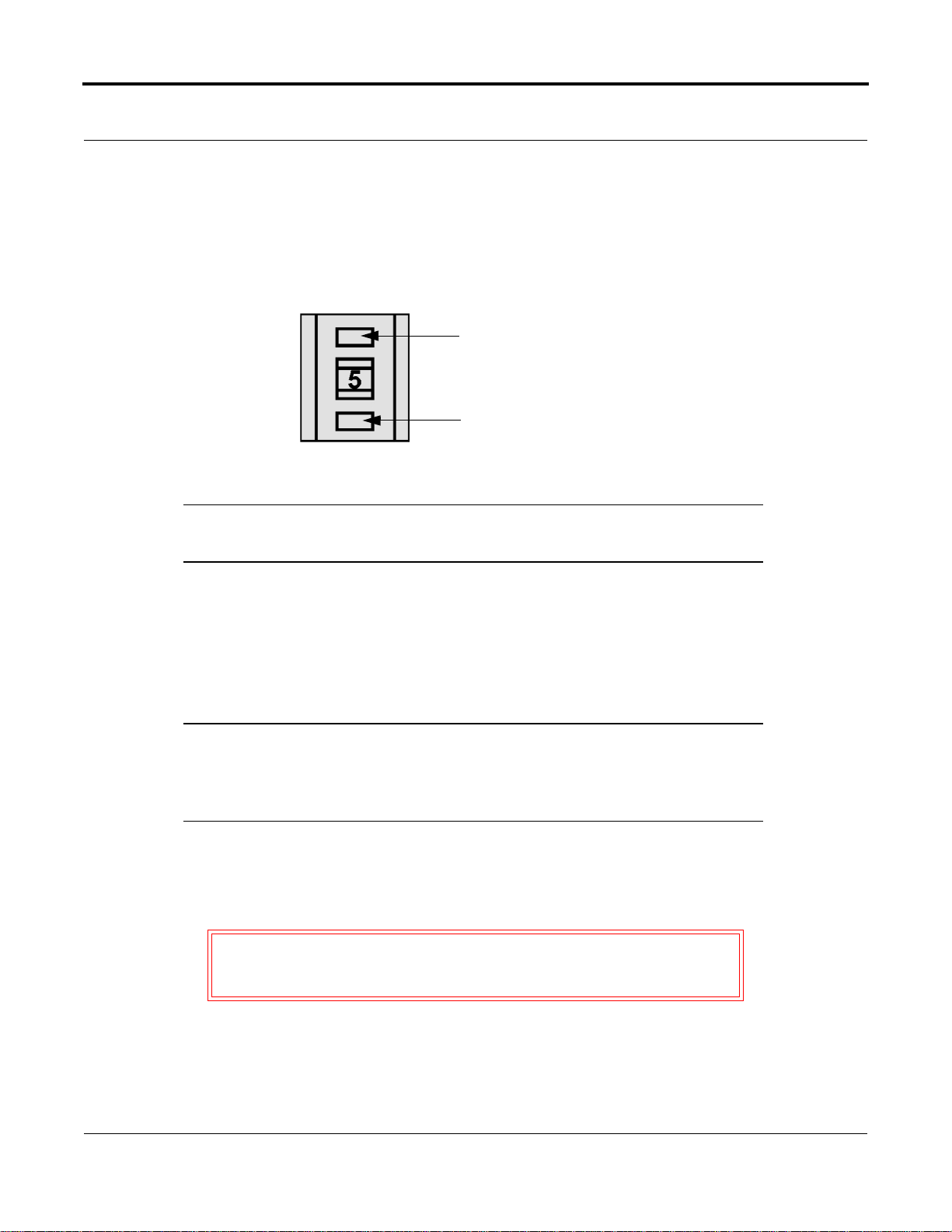
Terminating Your Internal Tape Drive
You must terminate the tape drive if:
• It is the only SCSI device—other than the SCSI host bus adapter—on the selected server or
workstation’s SCSI bus.
• It is the last SCSI device on the selected server or workstation’s SCSI bus.
T o terminate the tape drive, insert an act ive low-voltage differential (LVD) or multimode LVD/SE
terminator into the connector on one end of the SCSI r ibbon cabl e as shown in Figure 3-7. Y o u can use
a cable-end term i na tor as shown in Figure 3-7 or an inline terminator, whichever is most convenient.
Continue with the rest of the installation as usual.
Terminator
SCSI cable
Figu r e 3-7. Terminator Installation
3-12 May 2004 001596-01 Rev A07
Page 27
DLT VS80 Tape Drive Installation and Operations Guide
NOTE: If the SCSI cable that came with the SCSI host bus adapter already has a
terminator built i nto it, do not use anothe r te rminator. An example of such
a cable is shown in Figure 3-8.
Terminator
SCSI cable
(supplied with
host bus adapter)
Figu r e 3-8. SCSI Cable with Built-in Te rminator
3.3.3 Installing Your Internal Tape Drive
In the final installa tion stages, you install your tape drive in the server or worksta tion and connect the
SCSI and power cables.
To install your internal tape drive, follow these steps:
1. Shut down the operating system and power off the selected server or workstatio n.
2. Power off all perip heral devices such as printers and other SCSI devices.
AUTION Do not go to step 3 until you have completed steps 1 and 2.
C
Failure to follow these instr uctions may result in damage to
the tape drive or other devices.
001596-01 Rev A07 May 2004 3-13
Page 28
Chapter 3: DLT VS80 Instal la tio n
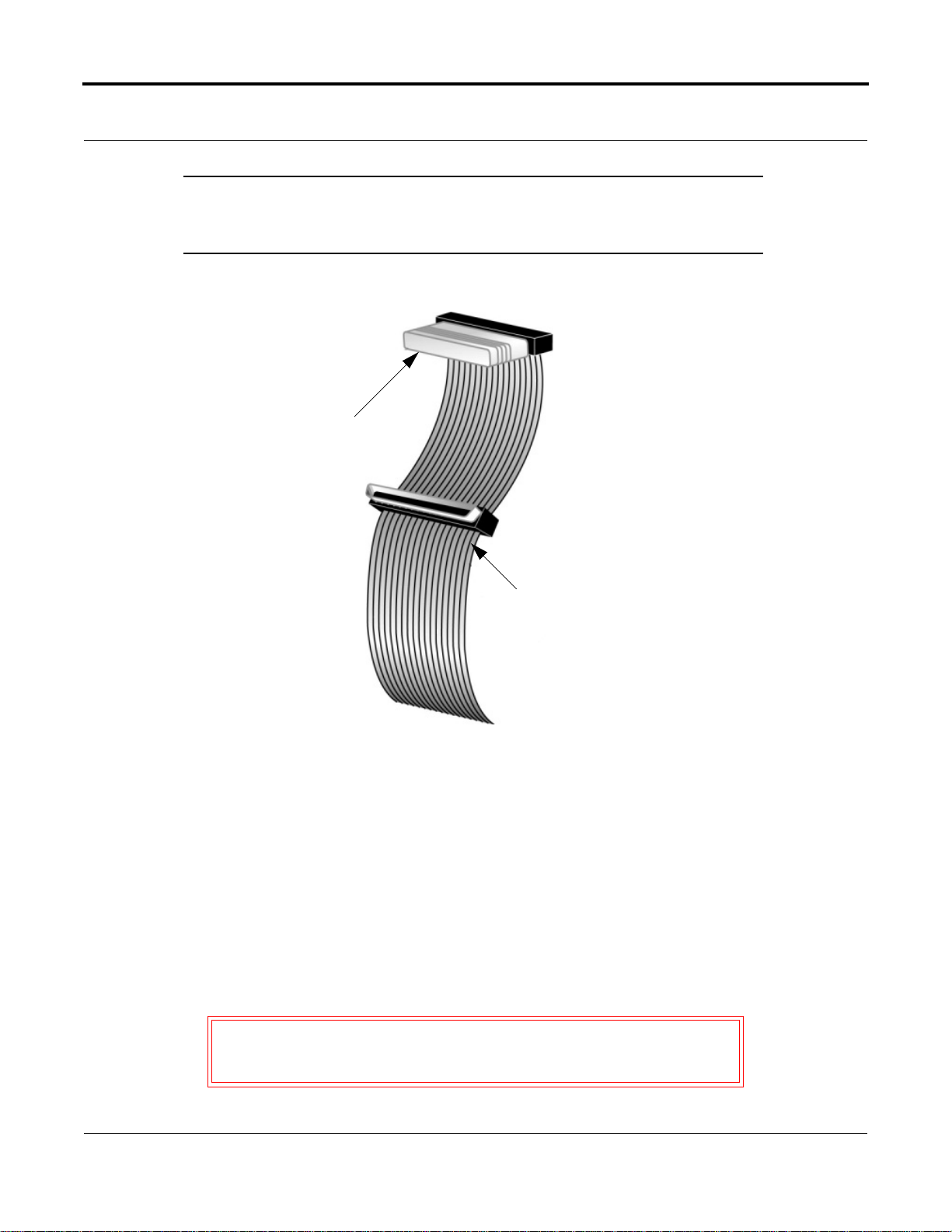
3. Remove the cover from the server or workstation as described in the server’s or works tation’ s
manuals. See Figure 3-9 as an example.
Figu r e 3-9. Remove the Workstation Cover (example shown)
4. Locate an available 5¼-inch drive bay and remove the front cover from the dr ive bay as described
in the server or workstati on’s manuals.
3-14 May 2004 001596-01 Rev A07
Page 29

DLT VS80 Tape Drive Installation and Operations Guide
5. Slide your tape drive into the open dri ve bay as shown in Figure 3-10.
Example of tower
drive bay
Figu r e 3-10. Tape Drive Installation in an Open Drive Bay
NOTE: Install an LVD/SE SCSI host bus adapter in the selected server or
workstation now, if necessary. For more information on SCSI host bus
adapter requirements, see “SCSI Requirements” on page 3-1.
Example of 2U enclosure
drive bay
001596-01 Rev A07 May 2004 3-15
Page 30

Chapter 3: DLT VS80 Instal la tio n
6. Select a SCSI cable with an open 68-pin, high-density connector.
7. Connect one end of the SCSI cable to the SCSI connector on the rear panel of your tape drive. The
SCSI connectors are keyed, preventing improper connection.
OTES:1If the SCSI cable does not fit the connector on your SCSI host
N
8. Connect the other end of the SCSI cable to the SCSI host bus adapter, aligning the colored stripe
on the ribbon cable with pin 1 on the SCSI host bus adapter’s connector.
9. Locate an available power cable in the host server or workstation and attach it to the power
connector on the rear panel of the tape drive. The connectors are keyed, preventing improper
connection.
bus adapter , you ei ther have an incompatible SCSI host bus
adapter or you need to pur chase a cable adapter. Contact your
Quantum sales representative or your SCSI host bus adapter
manufa ctu rer fo r information.
2 Refer to “Te rminating Your Internal Tape Drive” on
page 3-12 to determine if you need to host bus adapt er use an
LVD/SE term in ator with the SC SI cab le.
SCSI cable
(shown with
terminator
installed)
Figure 3-1 1 . SCSI and Power Cable Location (Internal Tape Drive)
Power cable
3-16 May 2004 001596-01 Rev A07
Page 31

DLT VS80 Tape Drive Installation and Operations Guide
10. Secure the tape drive with the mounting screws provided, eithe r in the sides or bottom of the tape
drive sled, as appropriate for the server or workstation chassis. See Figure 3-12.
CAUTION Using a screw that is too short c an res ult in inadequate
clamping force. Using a screw that is too long can cause
damage to the internal circuit cards. Please see the note
following Figure 3-12 for guidance.
Figu r e 3-12. Securing the Internal Tape Drive in the Installation Bay
NOTE: Some servers and workstations require mounting rails for internal
devices. Contact the manufacturer for specific information , as the
mounting rails have varying thicknesses. Consequently, if a different
screw is required to mount the tape drive, use the following guidelines.
001596-01 Rev A07 May 2004 3-17
Page 32

Chapter 3: DLT VS80 Instal la tio n
To comple te the inst alla t ion, fol low the s e steps :
1. Replace the cover on the server or workstation.
2. Attach the power cables to the server or workstation and all attached accessories.
3. Power on the server or workstation and allow its operating system to start.
4. Check your tape drive to make sure it is working properly by following the ste ps in “Testing Your
Tape Drive.”
3.4 Testing Your Tape Drive
Every time you power on your tape drive, it conducts a power-on self-test (POST). This test ensures
that the tape drive is working properly and is ready to use.
While POST is in progress, watch the front panel LEDs to see the progress and results of the test.
During POST, the following actions take plac e:
1. The LEDs illuminate all at once and then turn off.
2. The Ready (green) LED blinks during init ia lization and remains illuminated aft er POST.
3. The tape drive emits a buzzing sound as the tape drive calibrates the read/write head’s position.
POST is complete only after the buzzing sound stops.
POST takes several seconds to complete, after which the tape drive is ready to use.
NOTE: If POST does not work properly, refer to “Tr oubleshooting Your Tape
Drive” on page 3-19.
3-18 May 2004 001596-01 Rev A07
Page 33

DLT VS80 Tape Drive Installation and Operations Guide
3.5 Troubleshooting Your Tape Drive
This section provides both general troubleshooting guidelines and an LED-specific problem/solution
table to help you troubleshoot your tape drive.
3.5.1 General Troubleshooting Guidelines
If you have a problem when using the tape drive, first tr y to isolate the cause of the problem. For
example, if you have just installe d a new SCSI host bus adapter and the system will not sta rt, the cause
of the problem is likely to be the adapter.
When installi ng multiple items of ha rdware and software, install each item o ne at a time, restar ting the
system each time. Also, if you have installed multiple devices or software and then experience
problems, remo ve o r unin s tall each i n turn to establ i sh wh ich one is cau si ng the prob lem.
Remember that the system recognizes devices during power on. If you swap or connect a product when
the system is running, be sure to restar t the system. Restarting the system resets devic es and often
resolves problems. It is good practice to restart after adding a driver or installing new firmware.
3.5.2 Troubleshooting the Tape Drive
T able 3-2 on page 3-20 provides trouble shooting information on errors indicated by f ront panel LEDs,
including the following topics:
• None of the tape drive’ s LEDs illuminate.
• All of the LEDs on the front panel blink continually.
• The host server or workstation does not recogn ize the tape drive.
• There are fatal or non-fatal errors for whic h you cannot find the cause.
001596-01 Rev A07 May 2004 3-19
Page 34

Chapter 3: DLT VS80 Instal la tio n
If the LEDs on the front panel act differently than described in “Testing Your Tape Drive” on
page 3-18, the tape drive is not working properly. Table 3-2 helps you troubleshoot problems with the
tape drive:
Table 3-2 . Understanding Errors Indicated by Front Panel LEDs
Symptom Problem Solution
None of the tape drive’s
LEDs illuminate.
All of the LEDs on the front
panel blink continually.
The host server or
workstation does not
recognize the tape drive.
The tape driv e is not
receiving power.
An internal tape drive fa ult
has occurred.
The tape drive’s SCSI ID
might not be unique.
Check the tape drive’s power cable. If you have
a tabletop tape drive, check the power cable
connections. Plug the power cable into a
different power outlet.
• Reset the tape drive by holding the Unload
button down for six seconds or until all three
LEDs are illuminated. Release the Unload
button when the reset proces s begins.
• Power the tape drive off and then on again.
If it is an internal tape driv e, shut down and
power off the host serve r or workstation,
then power it back on and allow it to go
through its initialize process.
• Call technic al support if POST continues to
fail.
Change the tape drive’s SCSI ID:
1. Shut down and power off the host server or
workstation.
2. Power off the tape drive.
3. Change the tape drive’s SCSI ID. Refer to
pages page 3-4 and page 3-11 for
information on selecting the proper SCSI
ID.
4. Power on the tape drive.
5. Power on the host server or worksta tion.
Ensure th at al l device s on the S CSI bus are LVD
or SE.
The SCSI host bus adapter
might be incorrectly
configured.
The SCSI cable might be
loose.
The SCSI terminator might
be loose or missing.
Check the SCSI host bus adapter configuration.
Refer to the SCSI host bus adapter manuals for
instructions.
Check both ends of the SCSI cable, for both the
tabletop and int ernal tape drives.
• Tabletop tape drive: make sure the
terminator is properly seated on the open
SCSI connector on the rear panel of the tape
drive or on the last devic e on the SC SI bus.
• Internal tape drive: ma ke sure an LVD/SE
terminat or is in plac e on the e nd of th e SCS I
cabl e for th e ta p e dri v e.
3-20 May 2004 001596-01 Rev A07
Page 35

DLT VS80 Tape Drive Installation and Operations Guide
Table 3-2 . Understanding Errors Indicated by Front Panel LEDs (Continued)
Symptom Problem Solution
The host server or
workstation does not
recognize the tape drive.
(continued...)
The SCSI bus might be
improperly terminated.
The SCSI terminator might
not be at the end of the SCSI
bus or more than two
terminators might be present
on the SCSI bus.
The SCSI host bus adapter
might be in a defective
expansion slot.
The SCSI bus might be too
long.
• If your tape drive is the last or only device
on the SCSI bus, make sure the tape drive is
properly terminated.
• If the tape driv e is no t th e la st or on ly devi ce
on the SCSI bus, che ck all of the S CSI cable
connections and make sure the last device
on each en d o f the SCSI bus i s terminate d
and po wer ed on .
Note: The SCSI host bus ad apter must usually
be terminated.
Make sure the terminators are placed only at
each end o f the SCSI bus —o ne at the host bus
adapter and one on the last de vice on the bus,
for both the internal and tabletop tape drives.
Move the SCSI host bus adapter to a different
expansion slot.
Make sure the total length of the SCSI bus does
not exce ed these ANSI SCSI standards:
• 19 feet (6 meters) for an SE bus
• 40 feet (12 meters) for an LVD SCSI bus
with multiple devices
• 82 feet (25 meters) for an LVD SCSI bus
with a single device
• 10 feet (3 meters) for a Fast SCSI-2 or Ult ra
SCSI-1 bus.
There are fa tal or non-fatal
errors for which you cannot
find the cause.
The SCSI bus might be
improperly terminated.
• If the tape dr ive is the last or only device on
the SCSI bus, make sure the tape dri ve is
properly termi nated. Make sure only the last
device is terminated .
• If the tape driv e is no t th e la st or on ly devi ce
on the SCSI bus, check all S CS I cable
connections and make sure the last device
on the SCSI bus is terminat ed and powered
on.
The AC power source may
not be properly grounded
(tabletop tape drive only).
• Plug the tabletop ta pe drive’s power cable
into a powe r out let o n th e s ame cir cuit as the
host server or workstation.
• Plug the tabletop ta pe drive’s power cable
into a diffe r ent power outlet.
001596-01 Rev A07 May 2004 3-21
Page 36

Chapter 3: DLT VS80 Instal la tio n
Notes
3-22 May 2004 001596-01 Rev A07
Page 37

CHAPT ER 4
External Power LED
Chapter 4DLT VS80 Use
This chapter explains how to use your DLT VS80 tape drive. It describes the front panel LEDs and
controls, how to load and eject DLTtape IV data cartridges, how to use and care for DLTtape IV data
cartridges, and how to use the cleaning cartridge.
NOTE: For current information on operating system, application, and tape driver
compatibility, visit: www.quantum.com
4.1 Front Panel Controls and Indicators
This section ex pl ain s wh at the fro n t-p an el co ntrol s and in dica t or s are, an d how they are used. See
Figure 4-1.
(tablet op tape drive only)
Drive Error LED
Ready LED
Clea n/Media L E D
Figu r e 4-1. Tabletop Tape Drive Front Panel Layout
Unload button
Data cartridge door
001596-01 Rev A07 May 2004 4-1
Page 38

Chapter 4: DLT VS80 Use
4.1.1 Indicator Activity During Power-On Self-Test (POST)
Every time you power on your tape drive, it conducts a power-on self-test (POST). This test ensures
that your tape drive is work ing proper ly and i s ready t o use. While POST is in pr ogress, watc h the f ront
panel LEDs.
1. The LEDs illuminate all at once and then turn off.
2. The Ready (green) LED blinks during init ia lization and remains illuminated aft er POST.
3. The tape drive emits a buzzing sound as it calibrates the read/write head’s position. POST is
complete only after the buzzing sound stops.
POST takes sever seconds to complete, after which the tape drive is ready to use.
4.1.2 Indicator Activity During Tape Drive Operation
When your tape drive is in use, a variety of indicator LEDs can blink or be illuminated. Table 4-1
describes the circumstances under which one or more indicators are illuminated or blinking
immediately after POST.
Table 4-1 . Tape Drive Status and Indicator Activity
Tape Drive Status Indicator Activity
Power to the tape drive The Ready LED is on
No power to the tape drive The Ready LED is off
The tape drive detected an unrecoverable hard
error condition
The tape drive detected a recoverable
read/write error
The Drive Error LED is on
The Clean/Media LED blinks
4-2 May 2004 001596-01 Rev A07
Page 39

DLT VS80 Tape Drive Installation and Operations Guide
Table 4-2 describes what each front panel indicator means.
Table 4-2 . Indicat or Activity
Indicator State Operating Condition
Drive Error (amber) Blinking An unrecoverable tape drive error
or a POST error has occurred—
call Technical Support.
Off No tape drive Errors.
Ready (green) On Power to the tape drive.
Off No power to the tape drive.
Blinking (constant period & duty
Tape is in motion.
cycle)
Blinking (dual period & duty
Reserved.
cycle)
Clea n /M edia (a m b er ) Blink ing A hard re ad /writ e er r o r th a t is
probably recoverable has
occurred. Clean the tape drive.
The LED is off after completing a
cleaning cycle with a DLT1
cleaning cartridge or after loading
a properly formatted data
cartridge into th e tape drive.
Cycling the power to the tape
drive also turns off the LED.
Off Cleaning is not required.
All thr ee LED s On POST is st ar ting.
Blinking Firmware upgrade is in progress .
External Power LED On Power to the tape drive.
Off No power to the tape drive.
NOTE: Refer to Table3-2, “Understanding Errors Indicated by Front Panel
LEDs” on page 3-20 for help troubleshooting your tape drive.
001596-01 Rev A07 May 2004 4-3
Page 40

Chapter 4: DLT VS80 Use
4.2 Data Cartridge Use and Care
Your tape drive uses only DL Ttape IV data cartridges. Your tape drive can read—but not write to—
DLTtape IV data cartridges previously written in the DLT 4000 format.
NOTE: Your tape drive automatically unloads any other data cartridge types and
any data cartridges whose form at it cannot read. Make sure all data
cartridges that you use for writing are either unformatted or have been
used with your tape drive before loading them.
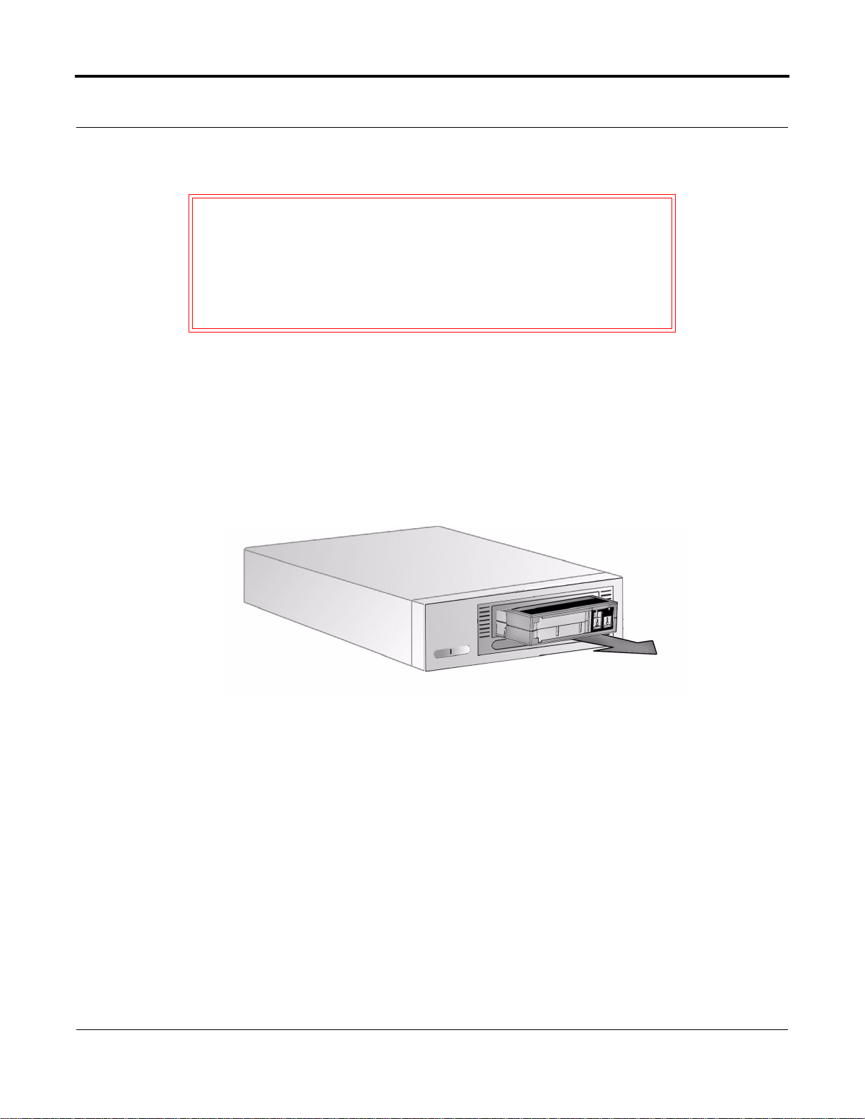
4.2.1 Loading a Data Cartridge
After the tape drive completes POST, insert the DLTtape IV data cartridge into the data car tridge slot,
oriented as shown in the Figure 4-2, and push the data cartridge gently into the tape drive until it stops.
Figu r e 4-2. Loading a DLTtape IV Data Cartridge
4-4 May 2004 001596-01 Rev A07
Page 41
4.2.2 Unloading a Data Cartridge
AUTION Remove the data cartridge from your tape drive before
C
powering off the tabletop tape drive or the host server or
workstation for an interna l tape drive. Leaving a data cart ridge
in the tape dr ive when power is off can result in data cartridge
and tape drive damage and may cause data loss because the
header/catalog data may not be properly written before the
tape drive loses power.
T o unload a data cartridge from your tape drive, follow these steps:
1. Press the Unload button or use your backup software to unload the da ta cartridge. The Ready LED
blinks while the tape drive rewinds the tape. When the tape drive has rewound the tape, it unloads
the data cartridge.
2. Gently remove the data cartri dge from the tape drive by pulling it directly out as shown in
Figure 4-3.
DLT VS80 Tape Drive Installation and Operations Guide
Figu r e 4-3. Unloading a DLTtape IV Data Cartridge
3. Return the data cartridge to its storage case to prolong data cartridge life.
001596-01 Rev A07 May 2004 4-5
Page 42

Chapter 4: DLT VS80 Use
4.2.3 Write-Protecting Data Cartridges
All DLTtape IV data cartridges have a write-protect switch to prevent accidental erasure of data.
Before loading a DLTtape IV data cartridge into your tape dr ive, make sure the write -protect swit ch on
the front of the data cartridge is in the position you need.
Orange
indicator
Write-protected
Write-protect switch
Write-enabled
Figu r e 4-4. Data Cartridge Write-Prot ect Swi tch
Slide the switch to the left to write-protect the data cartridge. A small orange rectangle is visible,
indicating that the data cartridge is write-protected.
Slide the switch to the right to allow your tape drive to write data to the data cartridge.
4-6 May 2004 001596-01 Rev A07
Page 43

DLT VS80 Tape Drive Installation and Operations Guide
4.2.4 Caring for Your Data Cartridges
To ensure the longest possible life for all of your DLTtape IV data cartridges, follow these guidelines:
• Do not drop or strike a data cartridge. Excessive shock can displace the tape leader, making the
data cartridge unusa ble and possibly damaging your tape drive.
• Store your DLTtape IV data cartridges in their storage cases.
• Do not expose your DLTtape IV data cartridges to direc t sunlight or sources of heat, including
portable heaters and heating duc ts.
• The operating temperature range for your DLTtape IV data cartridges is 50 ºF to 104 ºF (10 ºC to
40 ºC). The storage temperature range is 60 ºF to 90 ºF (16 ºC to 32 ºC). Always store your
DLTtape IV data cartridges in the ir sto rag e cases.
• If a DLTtape IV data cartridge has been exposed to temperatures outside the ranges specified
above, stabilize the da ta cartri dge at room temperatu re for the same amount of time it was exposed
to extreme temperature s, up to 24 hour s.
• Store your DLTtape IV data cartridges in a dust-free environment in which relative humidity is
always between 20% and 80% (noncondensing) . The ideal stor age relative humidity is 40%,
±
20%.
• Do not place DLTtape IV data cartridges near sourc es of electromagnetic energy or strong
magnetic fields , suc h as compu ter monitors, el ectri c mo to rs, s peak er s, or X-ra y equip me n t.
Exposure to electromagn etic energy or magnetic fields can destroy data on data cartridges.
• Place identification labe ls only in the slide-in slot on the front of the data cartridge.
• Never use any type of adhesive labels on your DLTtape IV data cartridges.
001596-01 Rev A07 May 2004 4-7
Page 44
Chapter 4: DLT VS80 Use
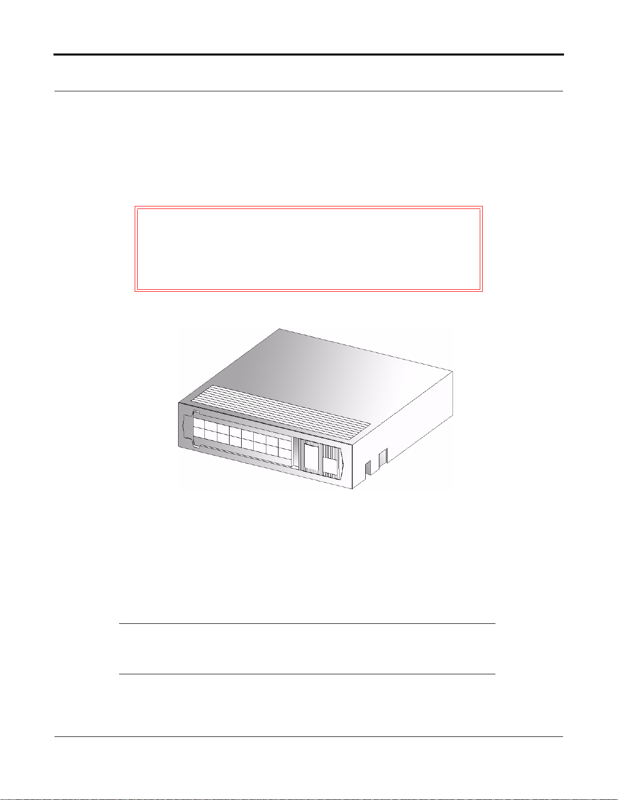
4.2.5 Using the Cleaning Cartridge
When the Clean/Media LED is illuminated, your tape drive’s read/write head may need to be cleaned.
Follow the instructi ons on page 4-4 to load the cleaning cartridge. Cleaning typically takes several
minutes, during which the Ready LED blinks.
C
AUTION Use only Quantum-approved cleaning cartridges in your tape
drive. Use of any other type of cleaning cartridge can damage
the read/write head in your tape drive. If you load any other
type of cleaning cartridge or method, your tape drive unloads
it within approximately 25 seconds. The part number for the
Quantum cleaning cartridge is BHXHC-02.
Figu r e 4-5. DLT Cleaning Cartridge
Each cleaning cartridge has a useful life of 20 cleanings. The cleaning cartridge inc l ude s a label with
20 small boxes printed on it. Always place a check mark in a box each time you use the cleaning
cartridge to clean the ta pe drive . Repla ce the cleaning cartridge when you have checked all the boxes.
When the clea ning cart rid ge ha s clean ed the rea d/write head, the Cl ean/ M ed ia LED t urn s off and the
tape drive ejects the cle aning cartridge.
NOTE: If any LEDs blink or if the Clean/Media LED is illuminated when you
insert another data cartridge immediately after cleaning, see Table 4-2 on
page 4-3 for more information.
4-8 May 2004 001596-01 Rev A07
Page 45

CHAPT ER 5
Chapter 5DLT VS80 Firmware
This chapter explains how to update your tape drive’s firmware from a DL Ttape IV data cartridge or
from a file on the host server or workstation.
5.1 Updating Tape Drive Firmware—Overview
The DLT VS80 automatically updates the tape drive’s fi rmware directly from a DLTtape IV data
cartridge containi ng the appropri ate information . The tape drive als o updates the tape dri ve’s firmware
from the host server or workstation. See the WRITE BUFFER command in the DLT1/VS80 SCSI
Interface Guide.
AUTION During a firmware update, take reasonable precautions to
C
prevent a power failure. During the firmware update process,
when the new firmware is a ctually be ing progr ammed into th e
Flash EEPROM, a power failure—but not a Bus Reset—
causes the tape drive’s controller module to become unstable.
001596-01 Rev A07 May 2004 5-1
Page 46

Chapter 5: DLT VS80 Firmware
5.2 Creating a Firmware Update Data Cartridge
T o perform the firmware update, you need a DLTtape IV data cartridge and a copy of the firmware
image. This image must be byte-written without compression onto the media. You must copy the
firmware image to the media instead of using a backup utility to transfer it to the tape.
NOTE: UNIX Systems: You can use the FTP utility to transfer the binary image
file onto the UNIX system. Be sure to specify “type image” before
performing the get or put operation. Doing so prevents extra characters
from being added to the image file, which would make the image fi le
invalid. The image file must be exactly 1286*512 Bytes in size. The data
must also be uncompressed.
5.3 Updating the Firmware
To update the tape drive’s firmware, follow the steps in this section.
AUTION Never power off the tape drive or the host server or
C
workstation during t he fi rmware upda te proc ess. Doi ng so can
damage the tape drive’s controller hardware.
5.3.1 Updating the Firmware
NOTE: Read these instructions completely before proceeding. All timing
indications are approximate.
1. If there is a DLT data cartridge currently in the tape drive, remove it before proceeding.
2. If possible, power cycle (turn the tape drive’s power off, then back on) and allow POST to
complete successfu lly. The tape drive will emit a buzzing sound as the head drives toward its
starting point (afte r 18 seconds). POST will complete after 20 seconds. When POST is complete
and no data cartridge is insert e d, only the Ready (green) LED is illuminated.
5-2 May 2004 001596-01 Rev A07
Page 47

DLT VS80 Tape Drive Installation and Operations Guide
3. Press and hold the Unload button on the tape drive ’s front panel until the LEDs are no longer
illuminated (appr oximately 12 seconds), then release the Unload button. The Ready LED flashes.
4. Within four sec onds , press and release the Unload button again. All LEDs should blink,
indicating that the tape drive is in firmware upgrade mode.
AUTION While the tape drive is in firmware upgrade mode, DO NOT
C
POWER OF F THE TAPE DRIV E, or the host server/
workstation (if conne cted), until the firmware upgrade pr ocess
is complete. You can damage the tape drive’s controller
hardware if you power off the tape drive.
5. Insert the Firmware Upgrade Dat a Cartridge into the tape drive. The tape drive then begins the
process of reading the image file from the data cartridge. All LEDs flash or are steadily
illuminated during the various phases of the upgrade process, which typically takes about five
minutes. If the firmware upgrade process completes successfully, the tape drive automatically
ejects the Firmware Upgrade Data Cartridge.
6. Power cycle (off, then on) the tape drive. The tape drive is now ready to use with the new
firmware.
Please observe the following conditions:
• You may need to restart your computer for it to recogni ze the tape drive.
• If the tape drive does not eject the Fir mware Upgrade Data Cartr idge, the firmware upgra de failed.
This may be because the data car tridge was not a val id Firmware Upgr ade Data Cartridge . If so, no
damage has occur red. Obt ain a valid Firmware Upgrade Data Cartridge and r epeat the proc ess. See
“Trou bleshooting the Firmware Upgrade” on page 5-4 for instructions on how to proceed.
• If you press and hold the Unl oad button for si x seconds (L EDs on) and rele ase i t before 12 se conds
(LEDs off), the tape drive executes a Front Panel Reset and runs POST.
• If you press and hold the Unload button for 12 seconds (LEDs on, then off) and then release it
without pressing it agai n within four seconds, the tape drive reverts to Ready mode, indica ted by
the Ready (green) LED.
001596-01 Rev A07 May 2004 5-3
Page 48

Chapter 5: DLT VS80 Firmware
5.3.2 Troubleshooting the Firmware Upgrade
If the fi rmware upgrade failed, the tape drive does not unload the F irmware Upgrade Data Cartridge at
the end of the process. Refer to Table 5-1 for troubleshooting information.
Table 5-1 . Firmware Upgrade Troubleshooting
Problem Indications/Solution
The data cartridge is not a valid Firm ware Upgrade
Data Cartridge.
The data cartridge contains a valid firmware
upgrade image file, but the flash EEPROM
programming process fails.
Indications: The tape drive does not attempt to
update the firmware. The tape drive resets and
leaves the data cartridge loaded to indicate that the
firmware update did not succ eed. No damage to the
tape drive or data cartridge results.
Solution:
1. Eject the data cartridge as des cribed in
“Unloading a Data Cartridge” on page 4-5.
2. Make a valid Firmware Upgra de Data Ca rtri dge
to solve this prob lem.
3. Repeat t he s tep s i n “U pd at ing t he Fi rm ware” on
page 5-2.
1. Eject the Firmware Upgrade Data Cartridge.
2. Power cycle the tape drive (off , then on).
3. Make a new Firmware Upgrade Data Cartridge.
4. Repeat the update process.
If the previous steps do not work, the tape drive’s
controller hardware is probably damaged and must
be replaced. The tape drive resets and runs POST,
which fails if the flash EEPROM does not contain a
valid firmware image. If this occurs, you must repair
the tape drive before using it again.
Call T echnical Support for repair service.
5-4 May 2004 001596-01 Rev A07
Page 49

Page 50

4001 Discovery Dr., Ste. 1100
Boulder, CO 80303
720.406.5700
May, 2004
001596-01
001596-01 Rev A07
001596-01 REV A07
 Loading...