

Page 1

3URGXFW0DQXDO 3URGXFW0DQXDO3URGXFW0DQXDO 3URGXFW0DQXDO
'/767DSH'ULYH
'/767DSH'ULYH
'/76
$
Page 2

DLT-S4 Product Manual, 81-81278-01 A01, July 2006, Made in USA.
Quantum Corporation provides this publication “as is” without warranty of any kind, either express or
implied, including but not limited to the implied warranties of merchantability or fitness for a particular
purpose. Quantum Corporation may revise this publication from time to time without notice.
COPYRIGHT STATEMENT
Copyright 2006 by Quantum Corporation. All rights reserved.
Your right to copy this document is limited by copyright law. Making copies or adaptations without prior
written authorization of Quantum Corporation is prohibited by law and constitutes a punishable violation of
the law.
TRADEMARK STATEMENT
Quantum, the Quantum logo, DLT, DLTtape, and the DLTtape logo are registered trademarks of Quantum
Corporation in the U.S. and other countries. The DLT logo, GoVault, DLTSage, and SuperLoader are
trademarks of Quantum Corporation.
All other trademarks are the property of their respective owners.
Page 3

Contents
Preface xiii
Chapter 1 Product Overview 1
Storage Capacity and Transfer Rates.............................................................................2
Tape Drive Models........................................................................................................... 2
Tape Drive Features.........................................................................................................4
Maximum Data Transfer Rate ........................................................................................ 5
Functional Specifications.................................................................................................6
Tape Drive Technology ...................................................................................................7
Tape Drive Components ................................................................................................. 8
Interface Types................................................................................................................ 11
Host Interface........................................................................................................... 11
Physical Characteristics.......................................................................................... 12
Chapter 2 Before You Begin 13
Warranty Note ................................................................................................................ 14
Safety Precautions ..........................................................................................................14
Tape Drive Handling and Storage Guidelines...........................................................15
Electrostatic Discharge Protection ............................................................................... 16
Pre-Installation Guidelines ........................................................................................... 17
DLT-S4 Product Manual iii
Page 4

Contents
Chapter 3 Cartridges 19
Choosing Compatible Cartridges ................................................................................ 19
Using Unsupported Cartridges.................................................................................... 21
Backward-read Compatibility Transfer Rate ............................................................. 22
Cartridge Handling and Storage Guidelines..............................................................23
Inspecting a Cartridge ...................................................................................................25
Write-protecting a Cartridge ........................................................................................ 29
Loading a Cartridge.......................................................................................................32
Unloading a Cartridge................................................................................................... 33
DLTSage WORM............................................................................................................34
DLTSage WORM Features.....................................................................................34
Formatting a Cartridge as DLTSage WORM ...................................................... 35
Chapter 4 Specifications 37
Physical Specifications................................................................................................... 38
Dimensions and Weights .............................................................................................. 39
Electromagnetic Field Specifications........................................................................... 40
Electromagnetic Emissions ....................................................................................40
Electromagnetic Interference and Immunity ...................................................... 41
Acoustic Noise Emissions .............................................................................................42
Chapter 5 Common Interface Information 43
SCSI Command Timeout...............................................................................................44
Rear Panel Connectors...................................................................................................46
Power Connector Pin Assignments...................................................................... 46
Loader/Library Interface Connector....................................................................46
Chapter 6 Parallel SCSI Interface 48
Rear Panel Connectors...................................................................................................49
SCSI Cable Connectors .................................................................................................. 49
SCSI Tape Drive Features..............................................................................................50
SCSI Stub and Cable Lengths ....................................................................................... 50
SCSI Connectors and Pin Assignments....................................................................... 51
DLT-S4 Product Manual iv
Page 5

Contents
Chapter 7 Fibre Channel Interface 55
Rear Panel Connectors...................................................................................................56
Fibre Channel Cable Connector ................................................................................... 56
Fibre Channel Tape Drive Features............................................................................. 57
Practical Considerations................................................................................................ 58
Hot-Swappable Cables ........................................................................................... 58
Power Usage ............................................................................................................58
Power Cycle (Tape Drive On) ............................................................................... 58
Failure to Obtain a Loop Address ........................................................................58
Fibre Channel Speed and Topology ............................................................................ 59
World-wide Names........................................................................................................ 61
Chapter 8 Serial Attached SCSI (SAS) Interface 62
Rear Panel Connectors...................................................................................................63
SAS Cable Connector.....................................................................................................64
SAS Tape Drive Features...............................................................................................64
Practical Considerations................................................................................................ 64
SAS Tape Drive Speed...................................................................................................65
World-wide Names........................................................................................................ 65
Chapter 9 Installing an Internal SCSI Tape Drive 66
Equipment Required...................................................................................................... 67
Installation Steps ............................................................................................................ 67
Rear Panel Connectors...................................................................................................68
Unpacking the Tape Drive............................................................................................69
Setting the SCSI ID ......................................................................................................... 69
Securing the Tape Drive in the System .......................................................................71
Connecting the Cables and Terminating the SCSI Bus.............................................74
Setting TERMPWR......................................................................................................... 77
Confirming the Installation...........................................................................................78
Adding an Additional Device ...................................................................................... 78
Using the Loader/Library Interface Connector......................................................... 79
DLT-S4 Product Manual v
Page 6

Contents
Chapter 10 Installing an Internal Fibre Channel Tape Drive 80
Equipment Required...................................................................................................... 81
Installation Steps ............................................................................................................ 81
Rear Panel Connectors...................................................................................................82
Unpacking the Tape Drive............................................................................................83
Securing the Tape Drive in the System .......................................................................83
Connecting the Cables................................................................................................... 86
Confirming the Installation........................................................................................... 87
Adding Additional Devices..........................................................................................88
Using the Loader/Library Interface Connector......................................................... 88
Chapter 11 Installing an Internal SAS Tape Drive 89
Equipment Required...................................................................................................... 90
Installation Steps ............................................................................................................ 90
Rear Panel Connectors...................................................................................................91
Unpacking the Tape Drive............................................................................................92
Securing the Tape Drive in the System .......................................................................92
Connecting the Cables................................................................................................... 95
Confirming the Installation........................................................................................... 96
Adding Additional Devices..........................................................................................97
Using the Loader/Library Interface Connector......................................................... 97
Chapter 12 Installing the Tabletop Tape Drive 98
Equipment Required...................................................................................................... 99
Installation Steps ............................................................................................................ 99
Rear Panel Connectors.................................................................................................100
Unpacking the Tabletop Tape Drive ......................................................................... 101
Selecting a Location for the Tabletop Tape Drive.................................................... 101
Setting the SCSI ID ....................................................................................................... 102
Connecting the Tape Drive to the Host Computer and Terminating the SCSI Bus.
103
Connecting the AC Power Cable ............................................................................... 105
Confirming the Installation.........................................................................................107
Adding an Additional Device .................................................................................... 107
Configuring the Tape Drive........................................................................................ 109
Using TERMPWR......................................................................................................... 109
DLT-S4 Product Manual vi
Page 7

Contents
Chapter 13 Using the Tape Drive 110
Front Panel Controls and LEDs.................................................................................. 111
Left LED.................................................................................................................. 111
Front Panel Controls.............................................................................................112
Power-On Self-Test ...................................................................................................... 113
Performing a Trial Backup.......................................................................................... 115
Firmware Update via the Host Interface ..................................................................116
Updating Firmware Using the Host Interface .................................................. 116
Creating a CUP/FUP Cartridge From Which to Update Firmware.............. 116
Firmware Update via the Library Tape Drive Interface.........................................118
Cleaning the Tape Drive.............................................................................................. 119
When to Clean the Tape Drive............................................................................ 119
Which Cleaning Cartridge to Use....................................................................... 119
Cleaning Cartridge Life Expectancy...................................................................120
Cleaning Cartridge Compatibility...................................................................... 120
Cleaning Instructions............................................................................................120
Cycle Time for Cleaning Cartridge..................................................................... 121
Optimizing Tape Drive Performance........................................................................ 121
Chapter 14 Troubleshooting 1 23
General Troubleshooting............................................................................................. 123
POST and SCSI Troubleshooting ...............................................................................124
Over Temperature Condition..................................................................................... 128
Chapter 15 Preparing the Tape Drive for Shipping 129
Appendix A Diagnostic Tools 131
Accessing the Tools......................................................................................................132
Device Drivers ..............................................................................................................132
TapeAlert.......................................................................................................................133
Medium Auxiliary Memory........................................................................................ 133
DLTSage.........................................................................................................................134
xTalk Management Console ....................................................................................... 135
DLTSage Dashboard and DLTSage Tape Security..................................................136
DLT-S4 Product Manual vii
Page 8

Contents
Appendix B Environmental Compliance 137
WEEE and RoHS Compliance.................................................................................... 137
Disposal of Electrical and Electronic Equipment .................................................... 138
Appendix C Regulatory Statements 139
Glossary 144
Index 153
DLT-S4 Product Manual viii
Page 9

Figures
Figure 1 Internal Tape Drive..................................................................................... 3
Figure 2 Tabletop Tape Drive...................................................................................3
Figure 3 Tape Drive Integrated Components ...................................................... 10
Figure 4 Receiver Area ............................................................................................ 16
Figure 5 Compatible Tape Cartridges................................................................... 20
Figure 6 Data Cartridge Care .................................................................................25
Figure 7 Cartridge Bottom View............................................................................ 26
Figure 8 Cartridge Reel Locks ................................................................................27
Figure 9 Opening the Media Access Door............................................................28
Figure 10 Inspecting Inside the Media Access Door.............................................28
Figure 11 Cartridge Write-protect Tab.................................................................... 30
Figure 12 Loading a Cartridge ................................................................................. 33
Figure 13 DLTSage WORM Button .........................................................................36
Figure 14 ADI/Loader Port Interface Schematic...................................................47
Figure 15 SCSI Connectors and Jumpers (Rear View)..........................................49
Figure 16 SCSI Connectors........................................................................................ 50
Figure 17 Fibre Channel Connectors and Jumper Block (Rear View) ................ 56
DLT-S4 Product Manual ix
Page 10

Figures
Figure 18 Fibre Channel Cable Connector.............................................................. 57
Figure 19 Fibre Channel Speed and Topology Jumper Block.............................. 59
Figure 20 SAS Connectors and Jumper Block (Rear View)..................................63
Figure 21 SAS Cable Connector ............................................................................... 64
Figure 22 SCSI Connectors and Jumpers (Rear View)..........................................68
Figure 23 Detail of the Empty SCSI ID Connector ................................................ 70
Figure 24 Tape Drive Mounting Holes — Right Side View................................. 72
Figure 25 Tape Drive Mounting Holes — Bottom View ...................................... 73
Figure 26 SCSI Cable with Built-in Terminator .....................................................75
Figure 27 SCSI Interface – Terminator Installation ............................................... 75
Figure 28 SCSI and Power Cable Locations ...........................................................76
Figure 29 Enabling TERMPWR................................................................................ 77
Figure 30 Fibre Channel Connectors and Jumper Block (Rear View) ................ 82
Figure 31 Tape Drive Mounting Holes — Right Side View................................. 84
Figure 32 Tape Drive Mounting Holes — Bottom View ...................................... 85
Figure 33 Connecting the Fibre Channel and Power Cables ...............................87
Figure 34 SAS Connectors and Jumpers (Rear View)...........................................91
Figure 35 Tape Drive Mounting Holes — Right Side View................................. 93
Figure 36 Tape Drive Mounting Holes — Bottom View ..................................... 94
Figure 37 Connecting the SAS and Power Cables ................................................ 96
Figure 38 Tabletop Tape Drive — Rear View ...................................................... 100
Figure 39 Tabletop SCSI ID Selector Switch.........................................................103
Figure 40 SCSI Chain — Single Device .................................................................105
Figure 41 AC Power Cable Connector Types....................................................... 106
Figure 42 SCSI Chain — Multiple Devices .......................................................... 109
Figure 43 Tape Drive Front Panel.......................................................................... 111
DLT-S4 Product Manual x
Page 11

Tables
Table 1 Maximum Transfer Rate............................................................................ 5
Table 2 Tape Drive Technology.............................................................................. 7
Table 3 Tape Drive Components............................................................................ 8
Table 4 Interface Speed and Options................................................................... 11
Table 5 Tape Drive Interface Physical Characteristics...................................... 12
Table 21 Backward-read Compatibility Transfer Rates ...................................... 22
Table 22 Write-protect Tab Positions.....................................................................31
Table 23 Physical Specifications............................................................................. 38
Table 24 Tape Drive Physical Dimensions............................................................ 39
Table 25 Unpackaged and Shipping Weights ......................................................39
Table 26 EMI Regulations and Certifications ....................................................... 40
Table 27 Electromagnetic Interference and Immunity Test Summary............. 41
Table 28 Acoustic Noise Emissions........................................................................42
Table 29 SCSI Command Timeout Values ............................................................ 44
Table 30 MSE Mode SCSI Connector Pin Assignments......................................51
Table 31 MSE LVD Mode SCSI Connector Pin Assignments ............................53
Table 32 Fibre Channel Speed Configuration ...................................................... 60
DLT-S4 Product Manual xi
Page 12

Tables
Table 33 Fibre Channel Topology Configuration................................................61
Table 34 SCSI ID Address Selections..................................................................... 70
Table 35 Interpreting Front Panel LEDs.............................................................. 112
Table 36 LED Lighting Pattern During POST .................................................... 114
Table 37 POST and SCSI Troubleshooting Guidelines .....................................125
Table 1 DLTSage Features................................................................................... 134
DLT-S4 Product Manual xii
Page 13

Preface
This document serves as an easy-to-use information source and product
catalog to familiarize Quantum customers and systems professionals with
the DLT-S4 tape drive system. The DLT-S4 tape drive is an extension of
the Quantum Digital Linear Tape (DLT
Audience The primary audience for this document consists of end users installing
and using the tape drive. The information in this document applies to the
internal tape drive, the library tape drive, and the tabletop tape drive.
Purpose This document provides information on the DLT-S4 tape drive including:
®
) product family.
• Product description
• Installation instructions
• Operation instructions
• Regulatory compliance
DLT-S4 Product Manual xiii
Page 14

Document Organization This document is organized as follows:
Preface
• Chapter 1, Product Overview
, provides an overview of the DLT-S4
tape drive system, including features, tape drive technology,
components, interface types, and functional specifications.
• Chapter 3, Cartridges
, provides information on recognizing,
handling, inspecting, write-protecting, loading, unloading, and
creating secure write-once read-many (WORM) cartridges.
• Chapter 2, Before You Begin
, provides unpacking and safe handling
guidelines you need to know before you begin installing and using
your DLT-S4 tape drive.
• Chapter 4, Specifications
, provides basic physical and emissions
specifications of the DLT-S4 tape drive.
• Chapter 5, Common Interface Information
, provides information
common to all interfaces.
• Chapter 6, Parallel SCSI Interface
, provides information specific to
the SCSI interface.
• Chapter 7, Fibre Channel Interface
, provides information specific to
the Fibre Channel interface.
• Chapter 8, Serial Attached SCSI (SAS) Interface
, provides information
specific to the SAS interface.
• Chapter 9, Installing an Internal SCSI Tape Drive
, provides
instructions for installing the internal SCSI tape drive.
• Chapter 10, Installing an Internal Fibre Channel Tape Drive
, provides
instructions for installing the internal Fibre Channel tape drive.
• Chapter 11, Installing an Internal SAS Tape Drive
, provides
instructions for installing the internal SAS tape drive.
• Chapter 12, Installing the Tabletop Tape Drive
, provides instructions
for installing the tabletop tape drive.
• Chapter 13, Using the Tape Drive
, provides information that you
need to use the tape drive, including front panel controls and LEDs,
POST, performing a trial backup, updating the firmware, cleaning the
tape drive, and information on how to optimize tape drive
performance.
• Chapter 14, Troubleshooting
DLT-S4 Product Manual xiv
, provides troubleshooting information.
Page 15

• Chapter 15, Preparing the Tape Drive for Shipping, provides
information on how the special soft-load mechanism “parks” and
“unparks” the tape drive for safe shipping and moving.
Preface
• Appendix B, Environmental Compliance
, provides information on
how the DLT-S4 tape drive complies with environmental standards,
and information on how to safely dispose of electric and electronic
equipment.
• Appendix A, Diagnostic Tools
, provides information about the
diagnostic tools to use with DLT-S4 tape drives.
• Appendix C, Regulatory Statements
, lists all the regulatory
statements for the tape drive.
This document concludes with a glossary and a detailed index.
Notational Conventions This document uses the following conventions:
Note: Notes emphasize important information related to the main
topic.
Caution: Cautions indicate potential hazards to equipment and are
included to prevent damage to equipment.
Warning: Warnings indicate potential hazards to personal safety and
are included to prevent injury.
This document uses the following terminology:
• Right side of the tape drive — Refers to the right side as you face the
component being described.
• Left side of the tape drive — Refers to the left side as you face the
component being described.
• Power cycle — Means to turn the tape drive or system off, then on
again.
DLT-S4 Product Manual xv
Page 16

Related Documents The following documents are related to the DLT-S4 tape drive:
Document No. Document Title Document Description
Preface
81-81281-xx DLT-S4 Interface
Reference Guide
81-81279-xx DLT-S4 Product
Specification
81-81283-xx DLT-S4 Quick Start
Guide
81-81639-xx DLTSage Dashboard
and DLTSage Tape
Security Quick Start
Guide
6464162-xx DLT Tape Drive Library
Interface Specification
81-81235-xx 2U Rackmount Quick
Start Guide
Provides command and
reference information on the
tape drive
Provides hardware,
performance, environment,
shock and vibration, and
regulatory specifications for
the tape drive
Provides instructions on how
to install and run the tape
drive
Provides instructions on how
to install and use DLTSage
Dashboard and DLTSage Tape
Security
Describes the interface
implemented for two-way
communication between a
tape drive and a library
Provides instructions on
installing tape drives into the
2U Rackmount unit
81-81610-01 xTalk Management
Console for Windows
User’s Guide
81-81612-01 xTalk Management
Console User’s Guide Command Line
Interface
Current SCSI standards documents available from www.t10.org
DLT-S4 Product Manual xvi
Provides instructions for using
xTalk Management Console
via a Windows interface
Provides instructions for using
xTalk Management Console
via a Linux or Solaris interface
Page 17

Preface
Document No. Document Title Document Description
• SCSI Architecture Model (SAM-3)
• SCSI Primary Commands (SPC-3)
• SCSI Parallel Interface (SPI-5)
• SCSI Stream Commands (SSC-3)
• Serial Attached SCSI (SAS-1.1)
• Fibre Channel Protocol (FCP-2)
• Fibre Channel Framing and Signaling (FC-FS-2)
• Fibre Channel Arbitrated Loop (FC-AL-2)
• Fibre Channel General Services (FC-GS-5)
SCSI Standards 0
Copies of the approved version of the SCSI standards may be obtained
from:
Global Engineering Documents
15 Inverness Way, East
Englewood, CO 80112
(800) 854-7179 or (303) 397-2740
Contacts Quantum company contacts are listed below.
Quantum Corporate Headquarters
To order documentation on this or other Quantum products, contact:
Quantum Corporation
141 Innovation Drive
Irvine, CA 92617
(949) 856-7800
(800) 284-5101
0
DLT-S4 Product Manual xvii
Page 18

Preface
Technical Publications 0
To comment on existing documentation send e-mail to:
doc-comments@quantum.com
Quantum Home Page 0
Visit the Quantum home page at:
http://www.quantum.com
Customer Support 0
The Quantum Customer Support Department provides a 24-hour help
desk that can be reached at:
North/South America: (949) 725-2100 or (800) 284-5101
Asia/Pacific Rim:
APAC Headquarters: (International Code) + 65 6334 0660
Specific countries: www.quantum.com/ServiceandSupport/
ContactServiceandSupport/DLTSupportAPAC//
Index.aspx
Europe/Middle East/Africa: (International Code) + 44 1256 848 766
Send faxes for the Customer Support Department to:
North/South America: (949) 725-2176
Asia/Pacific Rim: (International Code) + 65 6432 2830
Europe/Middle East/Africa: (International Code) + 44 1256 848 777
Send e-mail for the Customer Support Department to:
North/South America: http://www.quantum.com/am/service_support/
Index.aspx
Asia/Pacific Rim: apachelp@quantum.com
Europe/Middle East/Africa: eurohelp@quantum.com
DLT-S4 Product Manual xviii
Page 19

Chapter 1
1Product Overview
This chapter describes the features of the DLT-S4 tape drive system and
covers the following topics:
• Storage Capacity and Transfer Rates
• Tape Drive Models
• Tape Drive Features
• Maximum Data Transfer Rate
• Functional Specifications
• Tape Drive Technology
• Tape Drive Components
• Interface Types
DLT-S4 Product Manual 1
Page 20

Chapter 1 Product Overview
Storage Capacity and Transfer Rates
Storage Capacity and Transfer Rates 1
The DLT-S4 tape drive system provides:
Mode Storage Capacity Transfer Rate
Native 800 Gigabytes (GB) 60 Megabytes per second
(MB/second)
Compressed
a. 2:1 compression ratio.
a
1.6 Terabytes (TB) 120 MB/second
Tape Drive Models 1
The tape drive system is available in three models: an internal unit for
server installation (see figure 1
and a library model for installing in tape automation systems. The library
model (not shown) is similar to the internal model, but has a different
front bezel.
), a tabletop (or external) unit (see figure 2),
DLT-S4 Product Manual 2
Page 21

Figure 1 Internal Tape Drive
Figure 2 Tabletop Tape Drive
Chapter 1 Product Overview
Tape Drive Models
DLT-S4 Product Manual 3
Page 22

Chapter 1 Product Overview
Tape Drive Features
Tape Drive Features 1
The DLT-S4 tape drive system provides the following product features:
Feature Description
Media A streaming tape drive that uses half-inch wide
DLTtape S4 media
Form Factor A standard 5.25-inch full-height form factor to
simplify integration into system and tape library
solutions
Format
Tape Drive Cartridge
Compatibility
DLT-S4 DLTtape S4
(write/read)
SDLT 600 Super DLTtape II
(read only)
SDLT 320 Super DLTtape I
(read only)
Interface
Options
Capacity
Ultra320 SCSI
4 Gigabit (Gb) Fibre Channel
3 Gb SAS-1.1
a
a
Mode Value
Native capacity 800 GB
Compressed capacity 1.6 TB
b
(2:1 compression ratio)
a. Fibre Channel and SAS interfaces are not available with the
tabletop model.
b. In accordance with industry practice, a typical compression
ratio is quoted. Actual compression ratios depend on the
redundancy and kind of data files you write.
DLT-S4 Product Manual 4
Page 23

Chapter 1 Product Overview
Maximum Data Transfer Rate
Maximum Data Transfer Rate 1
Table 1 shows the maximum and burst data transfer rates for the DLT-S4
tape drive.
Table 1 Maximum Transfer
Rate
Compressed
Configuration Native
Burst Max
2:1 >4:1
Ultra320 SCSI 60 MB/sec 120 MB/sec 140 MB/sec 320 MB/sec
Fibre Channel 60 MB/sec 125 MB/sec 180 MB/sec 4 Gb/sec
SAS-1.1 60 MB/sec 125 MB/sec 180 MB/sec 3 Gb/sec
Note: Cable lengths and cable type may limit attainable transfer rates.
a. The interface limits burst rates, not the design of the tape drive or the media.
a
DLT-S4 Product Manual 5
Page 24

Chapter 1 Product Overview
Functional Specifications
Functional Specifications 1
This section provides performance data for the DLT-S4 tape drive.
Feature Value
Tape drive read/write transfer
a
rate
Native—60 MB per second
Compressed—120 MB per
second
Tracks 80 logical tracks
1280 physical tracks
Track density 2988 tracks per inch (tpi)
Linear bit density 256 Kb per inch (Kbpi)
Read/Write media speed 155 inches per second (ips)
Rewind media speed 200 inches per second
Linear search media speed 200 inches per second
Average rewind time
Maximum rewind time
Average access time
b
b
b
70 seconds
140 seconds
70 seconds
(from BOT)
Maximum access time
b
142 seconds
(from BOT)
Load to BOT
b
25 seconds
70 seconds (unformatted media)
Unload from BOT
b
25 seconds
Nominal media tension Stationary—3.0 ± 0.5 oz.
Operating speed—3.5 ± 0.5 oz.
Rewind—3.5 ± 0.5 oz.
a. Depending on data type, SCSI bus limitations, and the tape
system configuration.
b. Note that data is typical; times may be longer if error recovery
time is necessary.
DLT-S4 Product Manual 6
Page 25

Chapter 1 Product Overview
Tape Drive Technology
Tape Drive Technology 1
The DLT-S4 tape drive incorporates state-of-the-art technologies that
contribute to the SDLT architecture. Some of these ideas are trademarked,
others are patented. Table 2
comprise the DLT-S4 tape drive system.
Table 2 Tape Drive Technology
Technology Description
lists some of the important technologies that
Laser Guided
Magnetic Recording
Magneto Resistive
Cluster Heads
Advanced Partial
Response Maximum
Likelihood
Advanced Metal
Powder Media
Positive Engagement
Tape Leader
Buckling Mechanism
The DLT-S4 tape drive system is based on Quantum’s Laser Guided Magnetic
Recording (LGMR) technology. LGMR provides a unique combination of the
best optical and magnetic technologies, which results in dramatically higher
capacities by substantially increasing the number of recording tracks on the
data-bearing surface of the media.
Magneto Resistive Cluster (MRC) heads are a densely packed array of small
Magneto Resistive (MR) tape heads precisely positioned using advanced thinfilm processing technology.
Improving on Partial Response Maximum Likelihood (PRML) technology
traditionally used in disk drives and communication systems, Quantum’s
advanced PRML channel technology, co-developed with Lucent Technologies,
brings new levels of performance and capacity to high-performance linear tape
products.
Advanced Metal Powder (AMP) media is a state-of-the-art media using
durable metal powder technology for recording high densities of data. The
back side of AMP media receives a specially formulated coating to accept the
optical servo tracks, which ensures that the entire data-bearing side of the
media is available for recording data and eliminates the need for preformatting.
The positive engagement tape leader buckling mechanism engages the media
leader on cartridge load and disengages it on cartridge unload. It uses a metal
pin attached to the tape drive leader to link with molded clips permanently
attached to the media leader inside the cartridge.
DLT-S4 Product Manual 7
Page 26

Chapter 1 Product Overview
Tape Drive Components
Tape Drive Components 1
The DLT-S4 tape drive is designed as a total system. The system includes
a complex interaction of a number of important components including
the base mechanical assembly, the front panel assembly (bezel), and the
board assemblies. Table 3
Table 3 Tape Drive Components
Components Description
describes these components.
Base mechanical
assembly
The base mechanical assembly houses the tape control mechanical, actuator,
reel motor, load mechanism, eject button, and front-panel indicators. It
positions the actuator servo head over the correct tape track. It implements the
functions required to buckle and unbuckle the media and control the media
motion. It engages the media leader on cartridge load and disengages it on
cartridge unload.
• Auto load—The tape auto load is a soft-load and seating mechanism that is
tolerant of forced media loading; a media sensor is triggered upon cartridge
insertion, and after the media reaches a hard stop point, the auto load sensor
engages, pulling the cartridges the remaining distance onto the motor. On
media ejection, the assembly reverses the process and automatically ejects
the cartridge a fixed distance from the front of the tape drive.
• Base plate—Acts as the support platform for the other modules and for the
tape drive enclosure. It also includes the mounting holes (shock mounts)
used to install the tape drive into a server or tape library.
DLT-S4 Product Manual 8
Page 27

Components Description
Chapter 1 Product Overview
Tape Drive Components
Front panel assembly
(bezel)
The front panel assembly (bezel) performs these functions:
• Protects the front of the drive from physical damage
• Channels air flow through the system
• Aligns the cartridge when it is inserted into the system
• Provides label identifiers for the LEDs mounted on the front of the tape
drive
• Enables cartridge ejection
• Reduces internal environmental contamination with a built-in dust door
(internal and tabletop configurations only)
Board assemblies The board assemblies provide the main control function for the system and the
interface from the system to the host computer, library, or autoloader. This
provides the Advanced Partial Response Maximum Likelihood (PRML) feature
of the Quantum DLT-S technology.
There are three board assemblies:
• Pre-amplifier Board (PAB) — The PAB contains the preamplfier for the read
heads, and the write driver for the write heads.
• Motor Driver Board (MDB) — The MDB interfaces with the reel motor
drivers and hall sensors, actuator driver and sensors, sensor and motor
drivers for the soft load, LEDs for front-panel indicators, and eject button
signals.
• Drive Control Board (DCB) — The DCB is the main control card for the
DLT-S4 tape drive. It sends commands to the MDB to control and drive the
tape mechanism. The board interfaces with the PAB to send signals to the
head for reading and writing.
DLT-S4 Product Manual 9
Page 28
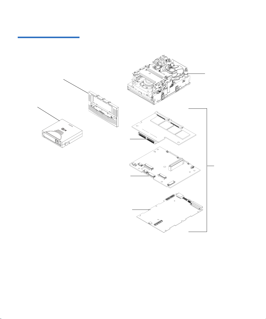
Figure 3 Tape Drive Integrated
Components
Chapter 1 Product Overview
Tape Drive Components
Front panel
assembly (bezel)
Cartridge
Base
mechanical
assembly
PAB
Board
assemblies
MDB
DCB
DLT-S4 Product Manual 10
Page 29

Chapter 1 Product Overview
Interface Types
Interface Types 1
This section contains the following information for the DLT-S4 tape drive:
• Host Interface
• Physical Characteristics
Host Interface 1 The interface supported by an DLT-S4 tape drive is dependent on the
kind of Drive Control Board (DCB) PWA installed. The DLT-S4 tape
drive comes in these interface types:
• Tabletop model with Ultra320 SCSI interface
• Internal model with either an Ultra320 SCSI interface, 4 Gb Optical
Fibre Channel interface, or SAS Interface
Table 4 Interface Speed and
Options
Interface speeds and protocol options are shown in table 4
Interface
Versions
Ultra320
SCSI
Fibre
Channel
SAS 1.5 Gb/second
a. The SCSI bus itself limits this rate, not the design of the tape
drive or media.
Speed (Maximum
Burst) Protocol Options
320 MB/second
1 Gb/second
2 Gb/second
4 Gb/second
3 Gb/second
a
Low Voltage Differential (LVD)
sense running up to 320 MB per
second burst
Ultra160 2/FAST-20/
Asynchronous
Class3
Connect to N port, NL port,
FL port, and F port
Serial SCSI Protocol (SSP)
.
DLT-S4 Product Manual 11
Page 30

Chapter 1 Product Overview
Interface Types
Physical Characteristics 1 Table 5 lists the physical characteristics for each interface of the tape
drive. These interfaces are available from the rear panel (per type, per
port).
Table 5 Tape Drive Interface
Physical Characteristics
Interface Versions Physical Characteristics
Parallel SCSI Ultra320
LVD
SCSI ID/TERMPWR connector style: 6-pin
Connector style: 68-pin high density SCSI
Fibre
Channel
Topology-constrained (drive automatically detects
topology)
4 Gb interface (drive automatically detects speed)
LC connector with 850 nanometer SFP transceiver
(supplied)
SAS-1.1 Point-to-point topology
3 Gb interface (drive automatically detects speed)
DLT-S4 Product Manual 12
Page 31

Chapter 2
2Before You Begin
Inappropriate or careless handling of DLT-S4 tape drive systems may
result in damage to the product. Follow the precautions and directions to
prevent damaging the DLT-S4 tape drive system. In addition, follow the
steps in Pre-Installation Guidelines
correct hardware for the system configuration.
This chapter provides the following important information you need to
know before you install and use your DLT-S4 tape drive:
on page 17 to ensure that you have the
• Warranty Note
follow so you do not void your warranty
• Safety Precautions
• Tape Drive Handling and Storage Guidelines
• Electrostatic Discharge Protection
• Pre-Installation Guidelines describes proper steps to take before
installing the tape drive in a system
DLT-S4 Product Manual 13
provides a general reminder of certain precautions to
Page 32

Chapter 2 Before You Begin
Warranty Note
W arranty Note 2
See the tape drive warranty before installing the tape drive; the tape
drive’s warranty could be voided if the installation guidelines and
restrictions are not closely followed.
Generally, the Limited Product and Limited Repair Warranties are
contingent upon proper use in the application for which the product is
intended, and do not cover the product if you perform any of the
following actions:
• Modify the product without the manufacturer’s written approval
• Subject the product to unusual physical, environmental, or electrical
stress, including damage caused by handling or shipping in
unapproved containers or packaging
• Disturb any warranty labels, or the integrity of the product in any
other way
• Remove or damage the serial number label to the extent that
warranty status of the product cannot be determined
Safety Precautions 2
For your safety, follow all safety procedures described here and in other
sections of the document.
• Turn off the system into which the DLT-S4 tape drive is to be
installed or attached before installing or removing the tape drive to
prevent the possibility of electrical shock or damage to the tape drive.
• Unplug the system that contains—or is to contain—the tape drive
from AC power before installing the tape drive to provide an added
measure of safety.
• Read, understand, and observe all label warnings.
DLT-S4 Product Manual 14
Page 33

Chapter 2 Before You Begin
Tape Drive Handling and Storage Guidelines
• The DLT-S4 tape drive uses a Class I laser product. This laser product
complies with 29 CFR 1200 and 29 CFR 1910 as applicable on the date
of manufacture.
Warning: If you open the tape drive chassis, you may become
exposed to invisible laser emission which could be
harmful if you are directly exposed to the beam.
Tape Drive Handling and Storage Guidelines 2
Damage to the DLT-S4 tape drive system can occur as the result of
careless handling, vibration, shock, or electrostatic discharge (ESD). For
more details on ESD, see Electrostatic Discharge Protection
Follow these guidelines to avoid damage to the tape drive:
Caution: Never power off the tape drive or the host while the tape
drive contains a cartridge. Failure to remove a cartridge
may result in cartridge or tape drive damage.
on page 16.
• Always handle the tape drive carefully and gently— a drop of ¼ inch
onto a bench or desktop can damage a tape drive.
• Hold the internal tape drive only by its sides.
• Never hold or carry the tape drive by inserting your fingers into the
receiver area on the front of the tape drive. You could damage the
receiver area if you lift or carry it in this manner.
• Do not bump, jar, or drop the tape drive. Use care when transporting
the tape drive.
• Do not place the tape drive so that it rests on its front bezel.
• Always gently place the tape drive flat and horizontal on an
appropriate ESD-protected work surface to keep the tape drive from
accidentally being knocked over.
• Do not stack objects on the tape drive.
DLT-S4 Product Manual 15
Page 34

Chapter 2 Before You Begin
Electrostatic Discharge Protection
• Do not expose the tape drive to dusty, humid, or smoke-filled areas,
or to excessive heat or cold (see Physical Specifications
required temperature and humidity conditions).
• Do not place foreign objects inside the tape drive’s receiver area (see
figure 4
).
on page 38 for
Figure 4 Receiver Area
Receiver area
Electrostatic Discharge Protection 2
Several electrical components of the DLT-S4 tape drive system are
sensitive to static electricity and electrostatic discharge (ESD). Even a
static buildup or discharge that is too slight to feel can be sufficient to
destroy or degrade a component’s operation.
To minimize the possibility of ESD-related damage to the system, the
tape drive’s manufacturer strongly recommends using both a
workstation anti-static mat and an ESD wrist strap. If the devices are
correctly installed and properly used, they reduce the buildup of static
electricity that might harm the system.
Follow these guidelines to avoid ESD damage to the tape drive:
• Use a properly fitted wrist strap or other suitable ESD protection.
• Observe proper ESD grounding techniques.
• Keep the internal tape drive in its antistatic bag until ready to install.
DLT-S4 Product Manual 16
Page 35

Chapter 2 Before You Begin
Pre-Installation Guidelines
• Place the tape drive in the antistatic bag before placing it in a
shipping container.
• Hold the internal tape drive only by its sides.
• Place the tape drive on a properly grounded anti-static work surface
pad while it is out of its protective antistatic bag.
• Do not pack other materials with the tape drive in its antistatic bag.
• Do not use the bag as a substitute for the work surface antistatic pad.
The outside surface of the bag may not have the same antistatic
properties as the inside surface. It could actually increase the
possibility of ESD problems.
• Do not remove either the tabletop tape drive cover or the internal/
library tape drive cover to use any test equipment to check
components on the PCBAs. There are no user-serviceable
components on the tape drive.
Pre-Installation Guidelines 2
Before you install the tape drive in a system, follow these steps. Also,
check the tape drive to be certain it is operating properly before installing
it in a system.
1 Unpack and review the contents of the box for any physical damage.
If you find damaged items, contact the tape drive sales representative
and the shipping company immediately.
2 Save the shipping box and packing materials in case you need to
move or ship the tape drive at a later date.
Caution: When returning a unit to Quantum for repair, you
must use the original or equivalent packing materials
or risk voiding your warranty.
3 Record the model and serial number of the DLT-S4 tape drive system
in the space provided below.
DLT-S4 Product Manual 17
Page 36

Chapter 2 Before You Begin
Pre-Installation Guidelines
These numbers provide specific information on the DLT-S4 tape
drive system and will be helpful if you must contact technical
support. You can find these numbers on the bottom of the tabletop
tape drive enclosure and on the top of the internal and library tape
drives.
Serial Number
Model Number
(usually begins with TC)
4 Check the enclosed SCSI, Fibre Channel, or SAS cable to ensure it is
(usually begins with QP, QX,
or QK)
compatible with the SCSI, Fibre Channel, or SAS controller card in
the host computer.
5 Check the SCSI, Fibre Channel, or SAS interface on the host computer
to ensure that it is compatible with the tape drive (see table 5
on
page 12 for a list of the possible interfaces that are available and the
various options with each).
6 Confirm that your back-up software and operating system are
compatible with the tape drive.
See
www.quantum.com for the most up-to-date compatibility
information.
DLT-S4 Product Manual 18
Page 37

Chapter 3
3Cartridges
This chapter discusses the cartridges that you can use in the DLT-S4 tape
drive. This chapter covers the following topics:
• Choosing Compatible Cartridges
• Using Unsupported Cartridges
• Backward-read Compatibility Transfer Rate
• Cartridge Handling and Storage Guidelines
• Inspecting a Cartridge
• Write-protecting a Cartridge
• Loading a Cartridge
• Unloading a Cartridge
• DLTSage WORM
read-many (WORM) cartridge]
[explains how create a secure archival write-once,
Choosing Compatible Cartridges 3
The only cartridge the DLT-S4 tape drive can both read and write to is the
DLTtape S4 cartridge.
DLT-S4 Product Manual 19
Page 38

Figure 5 Compatible Tape
Cartridges
Chapter 3 Cartridges
Choosing Compatible Cartridges
The DLT-S4 tape drive can read from, but not write to:
• Super DLTtape II cartridges formatted in the SDLT 600 tape drive
• Super DLTtape I cartridges formatted in the SDLT 320 tape drive
The DLTtape S4 cartridge is black and has a distinctive pattern molded
into the plastic, along with the DLTtape logo. The cartridge is made of
wear-resistant materials to reduce the potential for debris generation and
increase the life of the cartridge.
The cartridge’s geometry is similar to previous DLTtape cartridges to
simplify integration with existing tape library designs (see figure 5
). Its
keying feature, however, ensures that it cannot be loaded into previous
generation tape drives.
DLTtape S4 Data Cartridge (BLACK)
Super DLTtape I Data Cartridge (GREEN)
DLT-S4 Product Manual 20
Super DLTtape II Data Cartridge (BLUE)
Page 39

Chapter 3 Cartridges
Using Unsupported Cartridges
Using Unsupported Cartridges 3
DLT-S4 tape drives are intended to be used only with the cartridges
specified in Choosing Compatible Cartridges
Quantum DLT drives are tested with a variety of unsupported cartridges
and are designed to ensure that no damage occurs to either the tape drive
or the cartridge if a user attempts to use an unsupported cartridge.
If you try to insert an unsupported cartridge into the DLT-S4 drive, the
drive will not be able to accept it. Possible results are:
• You may not be able to insert the unsupported cartridge into the
drive.
• The unsupported cartridge may trigger the soft-load mechanism at
an inappropriate time, which may cause the soft-load mechanism to
stop at an improper location. While the soft-load mechanism is
stopped, the unsupported cartridge may not be completely loaded in
the drive, and the drive may not automatically eject the cartridge. (If
this happens, you must manually eject the cartridge by issuing an
EJECT command or by pressing the Eject button.)
on page 19. However,
• If the unsupported cartridge does manage to load properly, the drive
will not be able to buckle, read, or write to it. If this happens, a load
failure will be issued over the interface. (If this happens, you must
manually eject the cartridge by issuing an
pressing the
When a compatible cartridge is loaded correctly, the left LED lights either
green or orange. If you load, or attempt to load, an incompatible
cartridge, the left LED stays off (see Loading a Cartridge
DLT-S4 Product Manual 21
Eject button.)
EJECT command or by
on page 32).
Page 40

Chapter 3 Cartridges
Backward-read Compatibility Transfer Rate
Backward-read Compatibility Transfer Rate 3
The DLT-S4 tape drive includes a backward-read compatibility feature
that enables it to read Super DLTtape I and Super DLTtape II cartridges
(but not write to these cartridges). The following table lists the transfer
rates for backward-read cartridges.
Table 21 Backward-read
Compatibility Transfer Rates
Native Read
Transfer Rate in
DLT-S4 Tape
b
Drive
Format
a
Cartridge Type Native Capacity
Native Read
Transfer Rate
SDLT 600 Super DLTtape II 300 GB 36.0 MB/sec
SDLT 320 Super DLTtape I 160 GB 16.0 MB/sec
a. Tape drives older than the DLT-S4 will eject a data cartridge written with DLT-S4 format.
b. Transfer rates shown are the minimum when reading uncompressed data.
≥ 18.0 MB/sec
≥ 8.0 MB/sec
DLT-S4 Product Manual 22
Page 41

Chapter 3 Cartridges
Cartridge Handling and Storage Guidelines
Cartridge Handling and Storage Guidelines 3
DLTtape S4 cartridges are engineered to be reliable, robust, and durable.
They are manufactured to withstand 1,000,000 head passes and have a
shelf life of 30 years. By following these guidelines, you will greatly
reduce the chance that you will experience problems with the cartridges
or cause damage to the tape drive system.
Caution: The safety of data depends on proper care and handling of
cartridges.
Caution: Never power off the tape drive while it contains a
cartridge. Failure to remove a cartridge prior to power-off
may result in cartridge or tape drive damage.
For best results, follow these guidelines for data cartridge handling and
storage:
• Follow the handling instructions and observe the environmental
specifications provided in the plastic cartridge case.
• Inspect tape cartridges for damage as described in Inspecting a
Cartridge on page 25.
• Store cartridges vertically in their protective cases when not in use or
when archived (see figure 6
• Protect cartridges from shock, vibration, moisture, direct sunlight,
dust, smoke, and magnetic fields.
• Do not stack more than five cartridges on top of each other.
• Do not carry cartridges loosely in a box or any other container.
Allowing cartridges to jostle together exposes them to unnecessary
physical shock.
• When carrying cartridges in their cases, orient the cases so that the
grooves in the cases interlock. This prevents the cases from slipping
apart and falling.
• Do not drop the cartridge. A dropped cartridge may have dislodged,
loosened, or damaged internal components. If you drop a cartridge,
give it a thorough visual inspection (see Inspecting a Cartridge
page 25 for complete instructions).
DLT-S4 Product Manual 23
).
on
Page 42

Chapter 3 Cartridges
Cartridge Handling and Storage Guidelines
• Use only the slide-in labels provided with each cartridge or slide-in
bar code labels designed for use with DLT media. Slide labels into the
label slot on the cartridge (see figure 6
). Never apply adhesive labels
or “sticky” notes on the top, side, or bottom of tape cartridges, and do
not write on the cartridge.
• Do not write on the labels with debris-producing writing
instruments, such as graphite pencils and water-soluble felt pens.
• Other than the bar code label, ensure that nothing else is stuck to the
cartridge before inserting it into the tape drive. Loose labels and other
materials can cling to the bottom of the cartridge and get stuck in the
tape drive.
• Leave unused labels attached to the printed material (called the
u-card) within the cartridge case.
• Store any loose labels or other materials that are smaller than 4.5 x 4.5
inches (114.3 x 114.3 mm) separate from the cartridge. A loose label or
piece of paper accidentally inserted into the tape drive along with a
cartridge can prevent the hub reel and tape drive gear from meshing.
• Never touch the tape or media leader. Dust and oils from your skin
contaminate the tape and affect performance.
• Avoid unnecessarily opening the cartridge media access door (see
figure 9
). This may expose the media to contamination or physical
damage.
• Protect cartridges from shock, vibration, moisture, direct sunlight,
dust, smoke, and magnetic fields. Devices that may produce
magnetic fields, such as computer monitors, motors, or video
equipment can alter or erase data on the media.
• Observe the proper temperature and humidity conditions for
operating and storing cartridges as follows:
Temperature
Operating 10 °C to 40 °C (50 °F to 104 °F)
Storage (with data) 18 °C to 28°C (64 °F to 82 °F)
Humidity
Operating 20% to 80% non-condensing
Storage (with data) 40% to 60% non-condensing
DLT-S4 Product Manual 24
Page 43

Figure 6 Data Cartridge Care
Chapter 3 Cartridges
Inspecting a Cartridge
Note: If storage or transportation of a cartridge has exposed it to
temperature or humidity conditions outside the
specifications shown in the preceding table, allow the
cartridge to acclimate to the proper operating environment
for 24 hours before using it.
Store data cartridges vertically in
plastic cases
Use slide-in labels
Inspecting a Cartridge 3
Improper cartridge handling is the primary reason for tape drive
problems. To avoid losing data or damaging the tape drive, inspect the
cartridges:
• Before loading a new cartridge in the tape drive
• After dropping a cartridge or subjecting it to physical shock
DLT-S4 Product Manual 25
Page 44

Chapter 3 Cartridges
Inspecting a Cartridge
• When the tape drive becomes inoperable after loading a cartridge
• When you receive a shipment of cartridges that show any sign of
shipping damage
Follow these steps to inspect a tape cartridge:
1 Gently shake the cartridge and listen for loose pieces.
2 Remove the cartridge from its protective plastic case.
3 Check for loose debris attached to the cartridge, and for other
contamination (oily, slimy, or sticky substances) that may have built
up on the surface of the cartridge.
4 Check the cartridge for any obvious cracks or other physical damage.
Rotate the cartridge in your hands, looking for broken or missing
parts.
5 Rotate the cartridge to view the bottom (see figure 7).
Confirm that the spring-loaded hub on the bottom of the cartridge is
centered. Press the hub to ensure that the spring is functioning
properly and that the hub returns to its normal position.
Figure 7 Cartridge Bottom
View
Spring-loaded hub
Reel lock
DLT-S4 Product Manual 26
Page 45

Figure 8 Cartridge Reel Locks
Chapter 3 Cartridges
Inspecting a Cartridge
Check that both reel lock tabs (the small plastic tabs inside the reel
6
lock) are partially visible (see figure 8
).
One reel lock is located on the end of the cartridge that is inserted
into the tape drive. The other is on the bottom of the cartridge. The
reel locks are black.
Note: The reel locks can break if you drop the cartridge. If the
reel lock tabs are not visible, do not use the cartridge.
Reel lock
Reel lock
7
Open the media access door by pressing on the tab in the door pivot
notch (see figure 9
DLT-S4 Product Manual 27
). Ensure that you do not touch the media leader.
Page 46

Figure 9 Opening the Media
Access Door
Chapter 3 Cartridges
Inspecting a Cartridge
Tab in the door pivot notch
8 Compare what you see inside the media access door to figure 10.
Look for damage to the cartridge buckling clips, including:
• Bent or “toed-in” appearance on one or both clips
• Improper seating (clips should be fully retracted towards the left
side of the opening)
• Bending of the leader bar that supports the clips
Figure 10 Inspecting Inside the
Media Access Door
Leader bar
DLT-S4 Product Manual 28
Proper position
of cartridge
buckling clips
Cartridge buckling clips
excessively “toed-in”
Page 47

Chapter 3 Cartridges
Write-protecting a Cartridge
Examine the visible media leader (without touching it) for excessive
9
debris, oily or sticky residue, condensed droplets of moisture, or any
other signs of contamination.
10 Finally, check for proper operation of the cartridge’s write-protect tab
(see figure 11
This sliding tab, located on the end of the cartridge used for the label,
should snap smartly back and forth, and the orange tab should be
visible when the cartridge is set to provide write protection (you
cannot write over the data already on the media).
Caution: If a cartridge shows any signs of damage, do not use it.
).
If a cartridge is dropped, retrieve the data, back it up
on a new cartridge, and dispose of the dropped
cartridge. A dropped cartridge should not reused even
if it shows no signs of damage.
Write-protecting a Cartridge 3
Each cartridge has a write-protect tab, which you can use to prevent
accidental erasure of data. Before inserting the cartridge into the tape
drive, position the write-protect tab on the front of the cartridge (see
figure 11
Note: To ensure you don’t erase valuable data already written to a
) according to the kind of operations you expect to perform.
data cartridge, always make sure the cartridge is writeprotected before inserting it into the tape drive.
DLT-S4 Product Manual 29
Page 48

Figure 11 Cartridge Writeprotect Tab
Chapter 3 Cartridges
Write-protecting a Cartridge
Orange
indicator
rectangle
Writeprotect tab
• To enable write protection — Slide the write-protect tab to the left so
that the bright orange rectangle is visible. This is the visual reminder
that you cannot write data to the media.
You can read existing data; however, you cannot write over existing
data on the media, nor append additional data to the media.
•
T o disable write protection — Slide the write-protect tab to the right so
that the orange rectangle is not visible.
You can write over existing data on the media, and you can append
additional data to the media unless the cartridge is write-protected
via firmware (in other words, the cartridge has been formatted as a
DLTSage WORM cartridge; see DLTSage WORM
on page 34 for
details).
For more details about write-protecting a cartridge, see table 22
DLT-S4 Product Manual 30
.
Page 49

Chapter 3 Cartridges
Write-protecting a Cartridge
Table 22 Write-protect Tab
Positions
Write-protect
Tab Position
Orange Writeprotect
Result
Indicator
Before Loading the Cartridge
Enabled
(Slide tab to left)
Visible • You cannot write data to the
media
• You cannot overwrite existing
data on the media
• You cannot append
additional data to the media
Disabled
(Slide tab to
right)
Not Visible Unless the cartridge is write-
protected via firmware:
• You can write data to the
media
• You can overwrite existing
data on the media
• You can append additional
data to the media
After Loading the Cartridge and During Operation
If you move the
write-protect tab
from its right
(disabled)
position to its left
Visible If the tape drive is currently
writing to a cartridge, the writeprotect feature does not take
effect until after the current write
operation completes.
(enabled)
position
If you move the
write-protect tab
from its left
Not Visible The cartridge becomes write-
enabled after a variable number
of seconds.
(enabled)
position to its
right (disabled)
position
DLT-S4 Product Manual 31
Page 50

Chapter 3 Cartridges
Loading a Cartridge
Loading a Cartridge 3
Follow these steps to load a cartridge (see figure 12).
1 Insert the cartridge into the receiver on the front of the tape drive.
2 Push the front center of the cartridge into the tape drive until the soft-
load mechanism engages and mounts the tape.
The middle LED flashes to show that the media is loading. When the
media reaches the Beginning of Tape (BOT) marker, the middle LED
lights steadily.
The cartridge is now ready for use.
To verify that you have loaded a compatible cartridge, look at the left
LED for the following indications.
If the Left LED is... Then this cartridge is loaded...
Green DLTtape S4
Orange Super DLTtape I or Super DLTtape II
Off No cartridge is inserted or an incompatible
cartridge is inserted
For more information on choosing cartridges, see Choosing Compatible
Cartridges on page 19.
DLT-S4 Product Manual 32
Page 51

Figure 12 Loading a Cartridge
Chapter 3 Cartridges
Unloading a Cartridge
Left LED
Eject button
Middle LED
Unloading a Cartridge 3
Follow these steps to unload a cartridge (see figure 12).
Caution: Never turn off the tape drive or the host while the tape
drive contains a cartridge. Failure to remove a cartridge
prior to power-off may result in cartridge or tape drive
damage.
Do NOT rush removal of the cartridge. Wait until the tape
drive ejects the cartridge and the middle LED lights steady
before removing the cartridge.
1 Press the Eject button (or issue an appropriate system software
command).
The tape drive completes any active writing, then rewinds. The
middle LED flashes as the media rewinds. When the media is
finished rewinding, the tape drive ejects the cartridge and the middle
LED lights steadily.
DLT-S4 Product Manual 33
Page 52

Chapter 3 Cartridges
DLTSage WORM
Remove the cartridge from the tape drive and return it to its plastic
2
case to protect it from damage.
DLTSage WORM 3
DLTSage WORM is the firmware compliance management function of
DLTSage. This feature uses a Write Once, Read Many (WORM)
functionality, which allows you to securely archive data stored on a
DLTtape S4 cartridge written on a DLT-S4 tape drive. The firmware
allows you to append data to a cartridge, but you cannot rewrite,
reformat, or erase the data.
DLTSage WORM firmware is a standard feature of the DLT-S4 tape drive
and the DLTtape S4 cartridge. See Formatting a Cartridge as DLTSage
WORM on page 35 for instructions on how to create a WORM cartridge.
DLTSage WORM Features 3 This section details the many features of DLTSage WORM. For more
information, see
http://www.dlttape.com/technology/DLTSageWORM/index.aspx
Feature Description
Security The tape drive’s firmware places an electronic signature key on each cartridge to
ensure that data written to the media cannot be rewritten, reformatted, or erased.
• The key is a unique identifier that cannot be altered.
• The firmware allows you to append new data to the cartridge.
• The cartridge initialization process assures that only unformatted cartridges will
be WORM enabled.
Verification The verification is a two-part process.
• The DLT-S4 tape drive provides best-of-class verification through its ECC
algorithms.
• The firmware provides archive media verification and tamper verification with
time and date signatures.
DLT-S4 Product Manual 34
Page 53

Chapter 3 Cartridges
DLTSage WORM
Feature Description
Identification The identification applies to both the data and the cartridges.
• The storage management software issues a time and date stamp, which enables
you to locate and authenticate specific records using ISV compliant storage
management software.
• The cartridge used for DLTSage WORM is a standard DLTtape S4 cartridge. Use
the special yellow labels provided by Quantum to identify the WORM
cartridges.
Duplication The data stored on the DLTtape S4 cartridge can be downloaded to another storage
media through any ISV-compliant storage management software.
Formatting a Cartridge as DLTSage WORM
Some backup software applications work with DLTSage to allow you to
format a tape cartridge as DLTSage WORM directly via the backup
3
software user interface.
If your backup software application does not allow this, you can use
xTalk Management Console to create the DLTSage WORM cartridge. (See
xTalk Management Console
on page 135 for information about xTalk
Management Console.)
Follow these steps to format a cartridge with DLTSage WORM using
xTalk Management Console:
1 If xTalk Mangement Console is not installed on your computer,
download it now (see Accessing the Tools
on page 132 for
instructions on downloading).
2 Obtain a blank DLTtape S4 cartridge that you want to format as
DLTSage WORM. Ensure that the cartridge contains no data.
3 Insert the cartridge into the drive and wait for the tape drive to come
ready.
4 Launch xTalk Management Console.
5 Click the DLTSage WORM button on the toolbar (see figure 13).
DLT-S4 Product Manual 35
Page 54

Figure 13 DLTSage WORM
Button
Chapter 3 Cartridges
DLTSage WORM
The DLTSage WORM Wizard displays.
6 Click Format to continue.
The cartridge is formatted as a DLTSage WORM cartridge.
Further information and instructions are available in the xTalk
Management Console for Windows User’s Guide found in the
Help menu in
xTalk Management Console.
DLT-S4 Product Manual 36
Page 55

Chapter 4
4Specifications
This chapter provides the following specifications for the DLT-S4 tape
drive:
• Physical Specifications
• Dimensions and Weights
• Electromagnetic Field Specifications
• Acoustic Noise Emissions
The specifications noted are applicable to the drive itself and not as it is
integrated into an automation system. Testing performed to validate
these specifications was done with the internal tape drive and the
tabletop tape drive models.
DLT-S4 Product Manual 37
Page 56

Chapter 4 Specifications
Physical Specifications
Physical Specifications 4
Table 23 lists error types and environmental operating and storage limits
for the DLT-S4 tape drive.
Table 23 Physical Specifications
Data Integrity
Error Type Frequency
Detected, Unrecoverable Read < 1 error in 10
Undetected Read < 1 error in 10
Temperature
Operating 10 °C to 40 °C (50 °F to 104 °F)
Storage -40 °C to 66 °C (-40 °F to 150 °F)
Humidity
Operating 20% to 80% non-condensing
Storage 10% to 95% non-condensing
Safety Certifications
18
bits read
27
bits read
Meets UL 60950, GS mark, and EN60950/IEC 950 standards (EN60825-1: Information Technology
Equipment). See the DLT-S4 Product Specification for more detailed information.
Air Flow
10.4 CFM minimum with 0.09 in H
Note: Allow at least 100 mm of unobstructed space behind the tape drive for proper air flow.
O pressure drop
2
Electrical Rating (numbers describe the SCSI model)
Tabletop 85 to 264 VAC, 63 W typical,
100 W (power supply rating) maximum, 47 to 63 Hz
Internal +5 V, 4.9 A RMS, 6.2 A Peak, typical
+12 V, 0.7 A RMS, 2.7 A Peak, typical
DLT-S4 Product Manual 38
Page 57

Chapter 4 Specifications
Dimensions and Weights
Dimensions and Weights 4
Table 24 lists the dimensions and weights for the internal, library, and
tabletop tape drives.
Table 24 Tape Drive Physical
Dimensions
Dimension Internal Model Library Model Tabletop Model
Height (without the front
bezel)
(including the front bezel)
Width (without the front
bezel)
(including the front bezel)
Depth (from the rear of the
82.55 mm (3.25 in.)
85.73 mm (3.38 in.)
146.05 ± 1.143 mm
(5.75 ± .045 in.)
148.59 mm (5.85 in.)
203.20 mm (8.00 in.)
82.55 mm (3.25 in.)
85.73 mm (3.38 in.)
146.05 ± 1.143 mm
(5.75 ± .045 in.)
148.59 mm (5.85 in.)
204.47 mm (8.05 in.)
164.46 mm (6.48 in.)
174.75 mm (6.88 in.)
320.04 mm (12.60 in.)
front bezel)
(including the front bezel)
Note: The mounting hole pattern for the bottom and sides of the system is industry standard.
Table 25 Unpackaged and
Shipping Weights
212.73 mm (8.375 in.)
213.61 mm (8.41 in.)
Weight Internal Version Tabletop Version
Unpackaged weight
Shipping weight
a
2.38 kg (5.25 lbs.) 6.27 kg (13.82 lbs.)
b
3.77 kg (8.31 lbs.) 9.90 kg (21.83 lbs.)
a. Weights depend on the configuration.
b. The packaging used may change the shipping weight
DLT-S4 Product Manual 39
Page 58

Chapter 4 Specifications
Electromagnetic Field Specifications
Electromagnetic Field Specifications 4
Quantum tape drives are electrical devices; as such, this equipment
generates, uses, and may emit radio frequency energy. The tape drives
may emit energy in other frequencies, as well, as discussed in the
following sections.
Electromagnetic Emissions
Table 26 EMI Regulations and
Certifications
The internal tape drive model complies with Class A limits in a
2U Rackmount enclosure. The tabletop tape drive model complies with
4
Class B limits. The library tape drive model is subject to the enclosure
utilized in an automation system integration.
Table 26
certifications held by the DLT-S4 tape drive internal and tabletop models.
Type Regulation/Certification
EEC Directive 89/336 CE BS6527 (UK)
CFR 47, 1995 FCC Rules Part 15 (MDOC)
IECS-003 Canada
V-3/97.04 VCCI (Japan)
CNS 13438 BSMI (Taiwan)
AS/NZS 3548 C-tick (Australia/New Zealand)
lists electromagnetic interference (EMI) regulations and
EN55022 (EU)
EN55024 (EU)
DLT-S4 Product Manual 40
Page 59

Chapter 4 Specifications
Electromagnetic Field Specifications
Electromagnetic Interference and Immunity
4
The DLT-S4 tape drive internal and tabletop models were tested to the
performance limits listed in Table 27
(per legislative and customer
requirements). The drives were tested to the latest standards in effect on
the date of the test, and passed in all cases.
Table 27 Electromagnetic
Interference and Immunity Test
Summary
Required
Test Name Test Specification
Performance
EN55022: 2003 Radiated and Conducted Emissions
Radiated Electromagnetic Emissions
Conducted Electromagnetic Emissions
EN55022: 2003 Class B
Current Harmonics and Flicker Emissions Tests
AC Power Supply Harmonic Emissions EN61000-3-2 Pass
AC Power Supply Voltage Flicker EN61000-3-3 Pass
EN55024: 1998 Immunity Tests
Electrostatic Discharge Immunity EN61000-4-2 Criteria A
a
Radiated Electromagnetic Immunity EN61000-4-3 Criteria A
Electrical Fast Transient / Burst Immunity EN61000-4-4 Criteria B
Electrical Surge Immunity EN61000-4-5 Criteria B
Conducted Electromagnetic Immunity EN61000-4-6 Criteria A
Power Frequency Magnetic Field Immunity EN61000-4-8 Criteria A
AC Voltage Dips and Interrupts Immunity EN61000-4-11 Criteria B
a. The minimum legal requirement for this drive is Criteria B; however, the drive was tested to
and passed Criteria A.
DLT-S4 Product Manual 41
Page 60

Chapter 4 Specifications
Acoustic Noise Emissions
Acoustic Noise Emissions 4
This section lists acoustic noise emission levels, both as noise power and
sound pressure. The table provides the preliminary declared values per
Table 28 Acoustic Noise
Emissions
ISO 9296 and ISO 7779/EN27779. The values shown in table 28
maximum values based on 3 sigma limits from a distribution of tape
drives.
Mode Internal Tabletop
Noise Power Emission Level (LNPEc)
Idle Not applicable 5.4 Bel
Streaming 5.9 Bel 5.9 Bel
are the
Sound Pressure Level (LPAc)
Idle Not applicable 42 dB
Streaming 47 dB 53 dB
a. Sound pressure level measured at front of tape drive.
a
DLT-S4 Product Manual 42
Page 61

Chapter 5
5Common Interface
Information
This chapter provides interface specifications that apply to all variations
of the DLT-S4 tape drive, which include the following topics:
• SCSI Command Timeout
initiator waits for a response before it times out for each SCSI
command
• Rear Panel Connectors
rear of the tape drive, defines the connectors, and lists the power and
loader connector pinouts
lists the length of time the SCSI command
describes how to use the connectors on the
DLT-S4 Product Manual 43
Page 62

Chapter 5 Common Interface Information
SCSI Command Timeout
SCSI Command T imeout 5
This section lists the length of time the SCSI command initiator waits for a
response before it times out.
Table 29 SCSI Command
Timeout Values
Command Timeout
ERASE
6 hours (overwrite
entire media)
INQUIRY
LOAD/UNLOAD 16 minutes
LOCATE
LOG SELECT
LOG SENSE
MODE SELECT
MODE SENSE
PERSISTENT RESERVE IN
PERSISTENT RESERVE OUT
PREVENT/ALLOW MEDIA REMOVAL 500 milliseconds
READ
READ ATTRIBUTE
READ BLOCK LIMITS
500 milliseconds
6 hours
500 milliseconds
500 milliseconds
500 milliseconds
500 milliseconds
500 milliseconds
500 milliseconds
1 hour
500 milliseconds
500 milliseconds
READ BUFFER
READ POSITION
RECEIVE DIAGNOSTIC RESULTS
RELEASE (10)
RELEASE UNIT
DLT-S4 Product Manual 44
3 minutes
500 milliseconds
500 milliseconds
500 milliseconds
500 milliseconds
Page 63

Chapter 5 Common Interface Information
SCSI Command Timeout
Command Timeout
REPORT DENSITY SUPPORT
REPORT DEVICE IDENTIFIER
REPORT LUNS
REPORT SUPPORTED OPERATION CODES
REQUEST SENSE
RESERVE (10)
RESERVE UNIT
REWIND
SEND DIAGNOSTIC
SET DEVICE IDENTIFIER
SPACE
TEST UNIT READY
VERIFY
WRITE
500 milliseconds
500 milliseconds
500 milliseconds
500 milliseconds
500 milliseconds
500 milliseconds
500 milliseconds
6 minutes
20 minutes
500 milliseconds
6 hours (directory
may need rebuilding)
500 milliseconds
1 hour
1 hour
WRITE ATTRIBUTE
WRITE BUFFER (UPDATE FIRMWARE)
WRITE FILEMARKS
Note: For more information on SCSI commands, see the DLT-S4
500 milliseconds
10 minutes
1 hour
Interface Reference Guide (81-81281-xx).
DLT-S4 Product Manual 45
Page 64

Chapter 5 Common Interface Information
Rear Panel Connectors
Rear Panel Connectors 5
This section describes how to use the rear panel connectors that are
common to all models of the tape drive.
For the locations of these connectors, see the following illustrations:
Power Connector Pin Assignments
Loader/Library Interface Connector
•SCSI— Figure 15
• Fibre Channel— Figure 17
•SAS — Figure 20
Pin assignments for the 4-pin power connector are listed here. Pin 1 is
indicated by a solid red dot in the illustrations.
5
Pin Number Signal Name
1 +12 V DC
2 Ground (+12 V return)
3 Ground (+5 V return)
4+5 V DC
The connector for the library/tape drive interface is an RS-422 serial port
set to 9600 baud, 8 bits per character, no parity, and 1 stop bit. All data
5
sent to or from the library/tape drive interface consists of bit-wise
encoded hex values.
This 10-pin loader connector provides the signals used when the tape
drive is part of a loader/library configuration. The loader connector
provides a “universal port” that can support various serial interface
protocols. The electrical signals from the DLT-S4 tape drive need to be
translated to the appropriate serial interface protocol by a hardware and
software interface system.
on page 49
on page 56
on page 63
The Loader/Library Controller interface conforms to the T10 Committee
Automation/Drive – Transport Protocol (ADT) Specification (see
DLT-S4 Product Manual 46
www.t10.org).
Page 65

Figure 14 ADI/Loader Port
Interface Schematic
Chapter 5 Common Interface Information
Rear Panel Connectors
The loader connector part number is Molex, 89401-1010; it is a single row,
10x2 mm configuration. See figure 14
for a schematic representation of
the connector and for connector pin assignments.
For more information, see the DLT Tape Drive Library Interface Specification
(6464162-xx).
DLT-S4 Product Manual 47
Page 66

Chapter 6
6Parallel SCSI Interface
This chapter provides SCSI interface specifications associated with the
DLT-S4 tape drive, which includes the following topics:
• Rear Panel Connectors
• SCSI Cable Connectors
• SCSI Tape Drive Features
• SCSI Stub and Cable Lengths
• SCSI Connectors and Pin Assignments
For information on transfer rates and protocol options, see table 4
page 11.
For more information on the SCSI interface, see the DLT-S4 Interface
Reference Guide (81-81281-xx).
Also, see the latest SCSI reference documentation available at
on
www.t10.org.
DLT-S4 Product Manual 48
Page 67

Chapter 6 Parallel SCSI Interface
Rear Panel Connectors
Rear Panel Connectors 6
Figure 15 shows the location of the connectors on the rear panel of the
DLT-S4 SCSI configured internal tape drive. (See figure 38
for an illustration of the SCSI connectors on the tabletop model.)
Figure 15 SCSI Connectors
and Jumpers (Rear View)
on page 100
SCSI connector
(68 pin)
SCSI ID jumper
block (includes
TERMPWR Enable)
Loader/library
interface connector
(10 pin)
or denotes pin #1
Power
connector
(4 pin)
SCSI Cable Connectors 6
SCSI models of the DLT-S4 tape drive have two high-density 68-pin SCSI
connectors. Connect the tape drive to the computer using a SCSI cable
with the correct type of connector on each end. The tape drive operates
best when the computer and host end of the cable have one of the types of
connector shown in figure 16
other host-end connectors.)
DLT-S4 Product Manual 49
. (The tape drive will, however, operate with
Page 68

Chapter 6 Parallel SCSI Interface
SCSI Tape Drive Features
Figure 16 SCSI Connectors
High-density 68-pin Micro DB68 or
Mini DB68
SCA 80-pin Hot Swap Connector
Very High-density Interconnect
Connector
SCSI Tape Drive Features 6
The DLT-S4 tape drive conforms to the Ultra320 SCSI standard and
allows for a maximum burst rate of 320 MB per second.
Quantum recommends one DLT-S4 tape drive per bus, with a maximum
of two DLT-S4 tape drives per bus.
SCSI Stub and Cable Lengths 6
The longest stub length on the DLT-S4 PCBA is 1.64 inches, and the
maximum cable length for one DLT-S4 tape drive is 20 meters. The
maximum SCSI cable interconnect length is 10 meters total with a
maximum of two DLT-S4 tape drives on the bus.
To operate properly in Ultra320 mode, ensure that all SCSI cables and
terminators are Ultra320 (SPI-4) compatible.
For more information on the SCSI interface, see the DLT-S4 Interface
Reference Guide (81-81281-xx).
For information on transfer rates and protocol options, see table 4
page 11.
DLT-S4 Product Manual 50
on
Page 69

Chapter 6 Parallel SCSI Interface
SCSI Connectors and Pin Assignments
SCSI Connectors and Pin Assignments 6
This section shows the connector pin assignments for:
Table 30 MSE Mode SCSI
Connector Pin Assignments
• MSE Mode SCSI connector (see table 30
• MSE LVD Mode SCSI connector (see table 31
Signal Name Pin Number Pin Number Signal Name
Ground 1 35 -DB(12)
Ground 2 36 -DB(13)
Ground 3 37 -DB(14)
Ground 4 38 -DB(15)
Ground 5 39 -DB(P1)
Ground 6 40 -DB(0)
Ground 7 41 -DB(1)
Ground 8 42 -DB(2)
Ground 9 43 -DB(3)
Ground 10 44 -DB(4)
Ground 11 45 -DB(5)
)
)
Ground 12 46 -DB(6)
Ground 13 47 -DB(7)
Ground 14 48 -DB(P0)
Ground 15 49 Ground
DIFFSENS 16 50 Ground
TERMPWR 17 51 TERMPWR
Note: The minus sign (-) next to a signal indicates active low.
DLT-S4 Product Manual 51
Page 70

Chapter 6 Parallel SCSI Interface
SCSI Connectors and Pin Assignments
Signal Name Pin Number Pin Number Signal Name
TERMPWR 18 52 TERMPWR
Reserved 19 53 Reserved
Ground 20 54 Ground
Ground 21 55 -ATN
Ground 22 56 Ground
Ground 23 57 -BSY
Ground 24 58 -ACK
Ground 25 59 -RST
Ground 26 60 -MSG
Ground 27 61 -SEL
Ground 28 62 -C/D
Ground 29 63 -REQ
Ground 30 64 -I/O
Ground 31 65 -DB(8)
Ground 32 66 -DB(9)
Ground 33 67 -DB(10)
Ground 34 68 -DB(11)
Note: The minus sign (-) next to a signal indicates active low.
DLT-S4 Product Manual 52
Page 71

Table 31 MSE LVD Mode
SCSI Connector Pin
Assignments
Chapter 6 Parallel SCSI Interface
SCSI Connectors and Pin Assignments
Signal Name Pin Number Pin Number Signal Name
+DB(12) 1 35 -DB(12)
+DB(13) 2 36 -DB(13)
+DB(14) 3 37 -DB(14)
+DB(15) 4 38 -DB(15)
+DB(P1) 5 39 -DB(P1)
+DB(0) 6 40 -DB(0)
+DB(1) 7 41 -DB(1)
+DB(2) 8 42 -DB(2)
+DB(3) 9 43 -DB(3)
+DB(4) 10 44 -DB(4)
+DB(5) 11 45 -DB(5)
+DB(6) 12 46 -DB(6)
+DB(7) 13 47 -DB(7)
+DB(P) 14 48 -DB(P)
Ground 15 49 Ground
DIFFSENS 16 50 Ground
TERMPWR 17 51 TERMPWR
TERMPWR 18 52 TERMPWR
Reserved 19 53 Reserved
Ground 20 54 Ground
+ATN 21 55 -ATN
Ground 22 56 Ground
+BSY 23 57 -BSY
Note: The minus sign (-) next to a signal indicates active low.
DLT-S4 Product Manual 53
Page 72

Chapter 6 Parallel SCSI Interface
SCSI Connectors and Pin Assignments
Signal Name Pin Number Pin Number Signal Name
+ACK 24 58 -ACK
+RST 25 59 -RST
+MSG 26 60 -MSG
+SEL 27 61 -SEL
+C/D 28 62 -C/D
+REQ 29 63 -REQ
+I/O 30 64 -I/O
+DB(8) 31 65 -DB(8)
+DB(9) 32 66 -DB(9)
+DB(10) 33 67 -DB(10)
+DB(11) 34 68 -DB(11)
Note: The minus sign (-) next to a signal indicates active low.
DLT-S4 Product Manual 54
Page 73

Chapter 7
7Fibre Channel Interface
This chapter provides Fibre Channel interface specifications associated
with the DLT-S4 tape drive, which include the following topics:
• Rear Panel Connectors
• Fibre Channel Cable Connector
• Fibre Channel Tape Drive Features
• Practical Considerations
• Fibre Channel Speed and Topology
• World-wide Names
The Fibre Channel interface operates at transfer rates up to 4 Gb/second.
The Fibre Channel interface is ONLY available with the internal and
library models; it is not available with the tabletop model.
Fibre Channel can support up to 126 devices in a loop configuration.
Longwave transceivers (with fiber optic cable) support distances up to
10 kilometers; short pulsewave transceivers (with fiber optic cable)
support distances up to 500 meters.
For more information on transfer rates and protocol options, see table 4
on page 11.
For more information on the Fibre Channel interface, see the DLT-S4
Interface Reference Guide (81-81281-xx).
Also, see the latest Fibre Channel reference documentation available at
www.t10.org.
DLT-S4 Product Manual 55
Page 74

Chapter 7 Fibre Channel Interface
Rear Panel Connectors
Rear Panel Connectors 7
Figure 17 shows the location of the connectors on the rear panel of the
DLT-S4 Fibre Channel configured internal tape drive.
Figure 17 Fibre Channel
Connectors and Jumper Block
(Rear View)
Fibre Channel
port
Fibre Channel Jumper Block
Loader/library interface
connector (10-pin)
or denotes pin #1
Power
connector
(4-pin)
Fibre Channel Cable Connector 7
Fibre Channel models of the DLT-S4 tape drive (internal model only)
have one Fibre Channel port. The Fibre Channel cable connector looks
like the one shown in figure 18
DLT-S4 Product Manual 56
.
Page 75

Chapter 7 Fibre Channel Interface
Fibre Channel Tape Drive Features
Figure 18 Fibre Channel Cable
Connector
Fibre Channel Tape Drive Features 7
The DLT-S4 Fibre Channel tape drive supports the following features:
• Automatic speed negotiation, with transfer rates of:
• 1 Gb per second
• 2 Gb per second
• 4 Gb per second
• Automatic topology negotiation (the tape drive operates as an
NL_Port or N_Port):
• Arbitrated Loop—private loop, NL_Port to NL_Ports(s)
• Arbitrated Loop—public loop, NL_Port to NL_Ports(s) and one
FL_Port.
• Fabric attachment—N_Port to F_Port
• Point-to-Point attachment—N_Port to N_Port
• FCP-2 (SCSI-3 command set) for tape devices
• Class 3 level of service
• Basic and extended link services
• Hard assigned port address, when attached to a library.
The library has the ability to assign a hard address to the tape drive. If
no hard address is assigned to the tape drive, then a soft address is
taken initially.
DLT-S4 Product Manual 57
Page 76

Chapter 7 Fibre Channel Interface
Practical Considerations
Practical Considerations 7
This section describes considerations specific to the DLT-S4 Fibre
Channel tape drive.
Hot-Swappable Cables 7 Fibre Channel cables are “hot swappable,” which means that you may
connect and disconnect them with unit power turned on. Therefore,
unlike some other systems, the tape drive and computer may remain
powered on while you connect the DLT-S4 tape drive to the host
computer.
Power Usage 7 DLT-S4 Fibre Channel tape drives use slightly more power than SCSI-
configured tape drives. See the DLT-S4 Product Specification (81-81279-xx).
Power Cycle (Tape Drive On)
Failure to Obtain a Loop Address
DLT-S4 Product Manual 58
When the tape drive completes the power cycle process (including POST)
and the port is initialized, the Fibre Channel port is enabled and will
7
attempt to initialize on the attached Fibre Channel topology.
When the tape drive completes the power cycle process (tape drive
turned on and POST complete), the device is on-line and capable of tape
drive operations.
See Power-On Self-Test
If the tape drive is unable to obtain an address (fabric assigned,
previously assigned, hard assigned, or soft assigned), it goes into a non-
7
participating mode and immediately implicitly logs out all logged-in
ports.
If the tape drive experiences a power-on reset, or recognizes an
LIP (AL_PD, AL_PS), it does not retain a previously acquired address to
use during the next loop initialization.
on page 113 for information about POST.
Page 77

Chapter 7 Fibre Channel Interface
Fibre Channel Speed and Topology
Fibre Channel Speed and Topology 7
Although Fibre Channel DLT-S4 tape drives will auto-negotiate the speed
and topology, you may override the automatic selections by placing
jumpers on the Fibre Channel jumper block at the rear of the tape drive.
If you decide it is necessary to change the tape drive’s speed or topology,
use your fingers to move the jumpers to the pattern corresponding to the
speed or topology you want. Using this jumper block is optional.
Figure 19 Fibre Channel
Speed and Topology Jumper
Block
Note:
See:
• Figure 17
• Figure 19
• Table 32
The tape drive only checks the jumpers at a power cycle. To
change the speed or topology configurations after installation,
turn off the tape drive, move the jumpers as needed, and then
turn on the tape drive.
and topology
for the Fibre Channel jumper block location
for the empty jumper block that you use to set the speed
and table 33 for the various jumper setting combinations
DLT-S4 Product Manual 59
Page 78

Table 32 Fibre Channel Speed
Configuration
Chapter 7 Fibre Channel Interface
Fibre Channel Speed and Topology
To Select This
Speed
Put Jumper on
These Pins Result
1 Gb per second 7 and 8 Tape drive attempts to synchronize the link at 1 Gb per
second only
2 Gb per second 5 and 6 Tape drive attempts to synchronize the link at 2 Gb per
second only
4 Gb per second 3 and 4 Tape drive attempts to synchronize the link at 4 Gb per
second only
Auto-negotiate No jumpers Auto Speed Negotiate: Tape drive attempts to synchronize
• first at 4 Gb per second
•then at 2 Gb per second
• then at 1 Gb per second
5 and 6
AND
3 and 4
Auto Speed Negotiate: Tape drive attempts to synchronize
• first at 4 Gb per second
•then at 2 Gb per second
• then at 1 Gb per second
Note: Pins 1 and 2 are spare pins that are not used; there is no effect if they are jumpered or not
jumpered.
DLT-S4 Product Manual 60
Page 79

Table 33 Fibre Channel
Topology Configuration
Chapter 7 Fibre Channel Interface
World-wide Names
To Select This
Topology
Arbitrated Loop 11 and 12 Tape drive attempts to initialize the link in FC Arbitrated
Point-to-Point 9 and 10 Tape drive attempts to initialize the link in FC Point-to-Point
Auto-negotiate No jumpers Auto Topology: Tape drive attempts to
Note: Pins 1 and 2 are spare pins that are not used; there is no effect if they are jumpered or not
jumpered.
Put Jumper on
These Pins Result
Loop topology only
topology only
• first initialize in FC Arbitrated Loop topology
• then initialize in FC Point-to-Point topology
11 and 12
AND
9 and 10
Auto Topology: Tape drive attempts to
• first initialize in FC Arbitrated Loop topology
• then initialize in FC Point-to-Point topology
World-wide Names 7
Each DLT-S4 tape drive contains two unique, 64-bit world-wide names: a
node name for the tape drive, and one for the tape drive’s Fibre Channel
port. The tape drive reports the world-wide names to the host through
the
INQUIRY Command (12h). See the DLT-S4 Interface Reference Guide
(81-81281-xx) for more information.
DLT-S4 Product Manual 61
Page 80

Chapter 8
8Serial Attached SCSI (SAS)
Interface
This chapter provides SAS interface specifications associated with the
DLT-S4 tape drive, which include the following topics:
• Rear Panel Connectors
• SAS Cable Connector
• SAS Tape Drive Features
• Practical Considerations
• SAS Tape Drive Speed
• World-wide Names
The SAS interface is ONLY available with the internal and library models;
it is not available with the tabletop model.
For information on transfer rates and protocol options, see table 4
page 11.
For more information on the SAS interface, see the DLT-S4 Interface
Reference Guide (81-81281-xx).
Also, see the latest SAS reference documentation available at
DLT-S4 Product Manual 62
on
www.t10.org.
Page 81

Chapter 8 Serial Attached SCSI (SAS) Interface
Rear Panel Connectors
Rear Panel Connectors 8
Figure 20 shows the location of the connectors on the rear panel of the
DLT-S4 SAS configured internal tape drive.
Figure 20 SAS Connectors and
Jumper Block (Rear View)
SAS port
Unused jumper
block
DLT-S4 Product Manual 63
Loader/library interface
connector (10 pin)
or denotes pin #1
Power
connector
(4 pin)
Page 82

Chapter 8 Serial Attached SCSI (SAS) Interface
SAS Cable Connector
SAS Cable Connector 8
SAS models of the DLT-S4 tape drive (internal model only) have one SAS
port. The SAS cable connector looks like the one shown in figure 21
Figure 21 SAS Cable
Connector
.
SAS Tape Drive Features 8
The DLT S4 SAS tape drive supports the following features:
• Automatic speed negotiation, with speeds of:
• 1.5 Gb per second
• 3 Gb per second
•SAS-1.1
• Transport Layer Retries
Practical Considerations 8
SAS cables are “hot-swappable,” meaning that you may connect and
disconnect them with unit power turned on. Therefore, unlike some other
systems, the tape drive and computer may remain powered on while you
connect the DLT S4 tape drive to the host computer.
DLT-S4 Product Manual 64
Page 83

Chapter 8 Serial Attached SCSI (SAS) Interface
SAS Tape Drive Speed
DLT S4 SAS tape drives use slightly more power than SCSI-configured
tape drives. See the DLT-S4 Product Specification (81-81279-xx) for
additional information.
SAS Tape Drive Speed 8
SAS DLT-S4 tape drives auto-negotiate the speed. The tape drive
attempts to synchronize:
• first at 3 Gb per second
• then at 1.5 Gb per second
World-wide Names 8
Each DLT-S4 tape drive contains two unique, 64-bit world-wide names: a
node name for the tape drive, and one for the tape drive’s SAS port. The
tape drive reports the world-wide names to the host through the
Command (12h). See the DLT-S4 Interface Reference Guide (81-81281-xx) for
more information.
DLT-S4 Product Manual 65
INQUIRY
Page 84

Chapter 9
9Installing an Internal
SCSI Tape Drive
This chapter describes how to configure and install the DLT-S4 internal
SCSI tape drive.
This chapter includes the following information:
• Equipment Required
• Installation Steps
• Rear Panel Connectors
• Unpacking the Tape Drive
• Setting the SCSI ID
• Securing the Tape Drive in the System
• Connecting the Cables and Terminating the SCSI Bus
• Setting TERMPWR
• Confirming the Installation
• Adding an Additional Device
• Using the Loader/Library Interface Connector
Caution: Before you begin, review the safety, ESD, and handling
precautions described in Chapter 2
injury or damage to equipment.
DLT-S4 Product Manual 66
to avoid personal
Page 85

Chapter 9 Installing an Internal SCSI Tape Drive
Equipment Required
Equipment Required 9
You need the following items to install the tape drive in a system:
• Four (4) M3 x 8 mm long screws
• Screwdriver
• Jumpers (supplied)
• Internal Ultra320 SCSI cable, SPI-4 (or SPI-5) compatible
• Active Ultra320 SCSI terminator (if the SCSI cable is already
terminated at the end then you do not need this item)
Installation Steps 9
To install the tape drive, perform the following tasks in this order. Each
task is described in detail on the pages listed below.
Step No. Step Page
1
2
3
4
5
6
7
Unpack the tape drive. Page 69
Set the SCSI ID. Page 69
Secure the tape drive in the system. Page 71
Connect the cables and terminate the
SCSI bus.
Set TERMPWR. Page 77
Confirm the installation. Page 78
Add an additional device (optional). Page 78
Page 74
DLT-S4 Product Manual 67
Page 86

Chapter 9 Installing an Internal SCSI Tape Drive
Rear Panel Connectors
Rear Panel Connectors 9
Figure 22 shows the location of the connectors on the rear panel of the
DLT-S4 SCSI configured internal tape drive.
Figure 22 SCSI Connectors
and Jumpers (Rear View)
SCSI connector
(68 pin)
SCSI ID jumper
block (includes
TERMPWR Enable)
Loader/library
interface connector
(10 pin)
or denotes pin #1
Power
connector
(4 pin)
DLT-S4 Product Manual 68
Page 87

Chapter 9 Installing an Internal SCSI Tape Drive
Unpacking the Tape Drive
Unpacking the Tape Drive 9
Before you begin, clear a desk or table so that you can unpack the tape
drive.
Note: If the room in which you are working differs from the
temperature at which the tape drive was shipped or stored by
30 ºF (17 ºC) or more, let the tape drive acclimate to the
surrounding environment for at least 12 hours before opening
the shipping carton.
Unpack and inspect the tape drive for shipping damage. If you notice any
damage, report it both to the sales representative and to the shipping
company immediately.
Caution: Save the packing materials in case you need to move or
ship the tape drive in the future. When returning a unit to
Quantum for repair, you must use the original or
equivalent packing materials or risk voiding your
warranty.
If there is no damage to the tape drive, select a server or workstation to
host the tape drive, then move on to the following installation steps.
Setting the SCSI ID 9
Each device on the SCSI bus must have a unique SCSI ID address
assigned to it. Check the SCSI IDs on all other devices on the selected
server or workstation, including the SCSI host adapter, and select an
unused SCSI ID for the tape drive. The factory default SCSI ID for the
internal tape drive is 5 (no jumpers are installed on the jumper block). If
the tape drive’s factory default SCSI ID is not currently in use by another
device, you do not need to change the SCSI ID.
Caution: If you reset the SCSI ID, do not use ID 7, as that ID is
already in use by the SCSI host adapter.
DLT-S4 Product Manual 69
Page 88

Chapter 9 Installing an Internal SCSI Tape Drive
Setting the SCSI ID
Figure 23 Detail of the Empty
SCSI ID Connector
Table 34 SCSI ID Address
Selections
Note:
For specific recommendations for assigning SCSI IDs, refer to
the system or SCSI controller documentation.
You can set the SCSI ID from 0 to 15. To change the SCSI ID, use your
fingers to place the supplied jumpers on the 12-pin SCSI ID jumper block
as follows:
• Figure 22
shows the location of the jumper block on the rear panel of
the tape drive.
• Figure 23
shows the empty 12-pin jumper block that you use to set
the SCSI ID.
• Table 34
shows how to place the jumpers to obtain the desired SCSI
ID.
SCSI ID
01
2
3
Jumper
Block
SCSI ID
4
5 (default) 6
7
Jumper
Block
SCSI ID
89
10 11
Jumper
Block
SCSI ID
12 13 14
15
Jumper
Block
DLT-S4 Product Manual 70
Page 89

Chapter 9 Installing an Internal SCSI Tape Drive
Securing the Tape Drive in the System
Note: The computer system and the tape drive SCSI IDs are only
checked when you turn both the computer system and the
tape drive off and then on again. To change the SCSI ID after
installation, turn off the system, change the tape drive’s SCSI
ID, and then turn on the system.
Securing the Tape Drive in the System 9
This section describes how to mount and secure the tape drive in the
system. Because of the variety of mounting possibilities for tape drives,
the instructions presented here are general guidelines. Use these
instructions only as a guide for mounting the tape drive in the system.
Note: In some system configurations, it may be more convenient to
connect the SCSI bus and power cables to the tape drive before
securing it in the system.
Mount the tape drive in the system by performing the following steps:
1 Ensure that the host computer and all peripheral devices are turned
off.
2 Position the tape drive in the system and align the tape drive
mounting holes (side or bottom) with those in the system (see
figure 24
3 Secure the tape drive in the bay or chassis using four M3 x 8mm long
and figure 25).
screws.
Caution: The screws used to mount the tape drive must be
M3 x 8mm long. This kind of screw is exactly the
proper length and will not damage the tape drive.
DLT-S4 Product Manual 71
Page 90

Figure 24 T ape Drive Mounting
Holes — Right Side View
Chapter 9 Installing an Internal SCSI Tape Drive
Securing the Tape Drive in the System
Mounting holes
DLT-S4 Product Manual 72
Page 91

Figure 25 T ape Drive Mounting
Holes — Bottom View
Chapter 9 Installing an Internal SCSI Tape Drive
Securing the Tape Drive in the System
Mounting
holes
DLT-S4 Product Manual 73
Page 92

Chapter 9 Installing an Internal SCSI Tape Drive
Connecting the Cables and Terminating the SCSI Bus
Connecting the Cables and Terminating the SCSI Bus 9
You can connect the DLT-S4 tape drive to the host computer as a single
device, or as one of two total devices connected via a SCSI cable with
multiple SCSI connectors in a “chain” configuration.
If you are connecting two devices to the SCSI bus, connect only one tape
drive to the host computer at this time. Finish the installation procedure
and confirm that the host computer and tape drive are communicating
correctly (see Confirming the Installation
device (see Adding an Additional Device
Follow these steps to connect the tape drive to the host computer (see
SCSI Connectors and Pin Assignments
Note: Use care when connecting the cables to avoid bending or
damaging the connector pins.
1 Ensure that the tape drive, host computer, and all peripheral devices
(such as printers) are turned off.
) before adding the additional
).
on page 51 for more information).
Caution: Never connect the tape drive while the tape drive,
host system, or peripheral devices are turned on.
Doing so could result in damage to the tape drive or
other peripheral devices.
2 Disconnect any other SCSI devices from the SCSI bus at this time.
You can add them back on later (see Adding an Additional Device
3 Ensure that the SCSI cable(s) and terminator(s) are Ultra320 and SPI-4
).
(or SPI-5) compatible.
Note: SPI refers to SCSI Parallel Interface; you can learn more
from this standard at the Web site
4 Terminate the SCSI bus by making sure a terminator is installed in
www.t10.org.
the very last connector of the SCSI cable.
DLT-S4 Product Manual 74
Page 93

Chapter 9 Installing an Internal SCSI Tape Drive
Connecting the Cables and Terminating the SCSI Bus
If the SCSI cable you are using has a built-in terminator, you do not
need to add another terminator (see figure 26
for an example of such
a cable). If the cable is not terminated, then install an active Ultra320
SCSI terminator on the SCSI cable (see figure 27
).
Figure 26 SCSI Cable with
Built-in Terminator
Figure 27 SCSI Interface –
Terminator Installation
Note:
Built-in
terminator
SCSI cable
Terminator
There should be only one terminator at the end of the SCSI
bus.
SCSI cable
DLT-S4 Product Manual 75
Page 94

Figure 28 SCSI and Power
Cable Locations
Chapter 9 Installing an Internal SCSI Tape Drive
Connecting the Cables and Terminating the SCSI Bus
Connect one of the SCSI connectors on the SCSI cable to the SCSI
5
connector on the rear panel of the tape drive (see figure 28
). The SCSI
connectors are keyed, preventing improper connection.
6 If not already connected, connect the other end of the SCSI cable to
the connector in the SCSI host adapter, aligning the colored stripe on
the cable with pin 1 on the SCSI host adapter’s connector.
7 Locate an available DC power cable in the host computer and attach
it to the power connector on the rear panel of the tape drive (see
figure 28
(See Power Connector Pin Assignments
). The connector is keyed, preventing improper connection.
on page 46 for power pin
number assignments and signal names.)
8 Check all the cable and termination connections to ensure that they
are attached correctly, seated firmly, and secured.
SCSI cable (shown with
terminator installed)
DLT-S4 Product Manual 76
Page 95

Chapter 9 Installing an Internal SCSI Tape Drive
Setting TERMPWR
Setting TERMPWR 9
At least one device on the bus must supply terminator power
(TERMPWR).
• To enable TERMPWR — Install a jumper across pins 11 and 12 on the
SCSI jumper block (see figure 29
• To disable TERMPWR — Remove the jumper.
Figure 29 Enabling TERMPWR
).
TERMPWR Enable jumper
on jumper block
DLT-S4 Product Manual 77
denotes pin #11
denotes pin #12
Page 96

Chapter 9 Installing an Internal SCSI Tape Drive
Confirming the Installation
Confirming the Installation 9
To confirm the installation, turn on the host computer.
The screens displayed at power-on contain:
•BIOS
•Operating system
• SCSI controller information
If the first screen displays host adapter and SCSI ID information
indicating the drive is a Quantum product, then the installation was
successful.
If the installation was NOT successful, see POST and SCSI
Troubleshooting on page 124.
Adding an Additional Device 9
Once you have successfully confirmed the installation of your tape drive,
you may add one additional device to the SCSI bus.
Note: Use care when connecting the cables to avoid bending or
damaging the connector pins.
1 Ensure that all devices have unique SCSI IDs (see Setting the SCSI ID
on page 69).
2 Ensure that the tape drive, host computer, and all peripheral devices
(such as printers) are turned off.
Caution: Never connect the tape drive while the tape drive,
host system, or peripheral devices are turned on.
Doing so could result in damage to the tape drive or
other peripheral devices.
3 Make sure that all the SCSI cables and terminators are SPI-4 (or SPI-5)
compatible.
DLT-S4 Product Manual 78
Page 97

Chapter 9 Installing an Internal SCSI Tape Drive
Using the Loader/Library Interface Connector
Connect all additional tape drives and peripheral devices to the host
4
computer’s SCSI cable.
5 Ensure that a terminator is installed on the very last SCSI connector
on the SCSI cable.
Note: Regardless of which device terminates the SCSI bus, that
device must have power applied and be powered on for
proper termination to occur.
6 Check all the cable and termination connections to ensure that they
are attached correctly and seated firmly.
7 Turn on power to the system and all attached devices.
8 Confirm the installation (see Confirming the Installation on page 78).
Using the Loader/Library Interface Connector 9
This connector is only used for tape drives installed in loaders/libraries.
If your system requires it to be used, it should have been pre-assembled
at the factory. For more information about the loader/library connector,
see Loader/Library Interface Connector
DLT-S4 Product Manual 79
on page 46.
Page 98

Chapter 10
10Installing an Internal Fibre
Channel Tape Drive
This chapter describes how to configure and install the DLT-S4 internal
Fibre Channel tape drive.
This chapter includes the following information:
• Equipment Required
• Installation Steps
• Rear Panel Connectors
• Unpacking the Tape Drive
• Securing the Tape Drive in the System
• Connecting the Cables
• Confirming the Installation
• Adding Additional Devices
• Using the Loader/Library Interface Connector
Caution: Before you begin, review the safety, ESD, and handling
precautions described in Chapter 2
injury or damage to equipment.
DLT-S4 Product Manual 80
to avoid personal
Page 99

Chapter 10 Installing an Internal Fibre Channel Tape Drive
Equipment Required
Equipment Required 10
You need the following items to install the tape drive in a system:
• Four (4) M3 x 8 mm long screws
• Screwdriver
• Fiber optic cable
Installation Steps 10
To install the tape drive, perform the following tasks in this order. Each
task is described in detail on the pages listed below.
Step No. Step Page
1
2
3
4
5
DLT-S4 Product Manual 81
Unpack the tape drive. Page 83
Secure the tape drive in the system. Page 83
Connect the cable. Page 86
Confirm the installation. Page 87
Add additional devices (optional). Page 88
Page 100

Chapter 10 Installing an Internal Fibre Channel Tape Drive
Rear Panel Connectors
Rear Panel Connectors 10
Figure 30 shows the location of the connectors on the rear panel of the
DLT-S4 Fibre Channel internal tape drive.
Figure 30 Fibre Channel
Connectors and Jumper Block
(Rear View)
Fibre Channel
port
Fibre Channel Jumper Block
DLT-S4 Product Manual 82
Loader/library interface
connector (10-pin)
or denotes pin #1
Power
connector
(4-pin)
 Loading...