

Page 1

$
'/767DSH'ULYH
'/767DSH'ULYH
,QWHUIDFH5HIHUHQFH*XLGH ,QWHUIDFH5HIHUHQFH*XLGH
'/76
,QWHUIDFH5HIHUHQFH*XLGH
Page 2

DLT-S4 Interface Reference Guide, 81-81281-04 A01, January 2008, Made in USA.
Quantum Corporation provides this publication “as is” without warranty of any kind, either express or
implied, including but not limited to the implied warranties of merchantability or fitness for a particular
purpose. Quantum Corporation may revise this publication from time to time without notice.
COPYRIGHT STATEMENT
Copyright 2007 by Quantum Corporation. All rights reserved.
Your right to copy this document is limited by copyright law. Making copies or adaptations without prior
written authorization of Quantum Corporation is prohibited by law and constitutes a punishable violation of
the law.
TRADEMARK STATEMENT
Quantum, the Quantum logo, DLT, DLTtape, and DLTtape logo are registered trademarks of Quantum
Corporation in the U.S. and other countries. The DLT logo, DLTSage, and StorageCare trademarks of
Quantum Corporation. LTO and Ultrium are trademarks of HP, IBM, and Quantum in the U.S. and other
countries.
All other trademarks are the property of their respective companies.
Page 3

Contents
Preface xxviii
Chapter 1 Introduction 1
Background Information About SCSI............................................................. 1
Parallel SCSI Characteristics .....................................................................2
Fibre Channel Characteristics ................................................................... 3
Serial Attached SCSI Characteristics........................................................ 4
Chapter 2 Task Management 5
Task Management by Transport Layer Overview ........................................ 6
Task Management Function ............................................................................. 7
TARGET RESET.......................................................................................... 7
LOGICAL UNIT RESET............................................................................. 7
CLEAR TASK SET ...................................................................................... 8
ABORT TASK..............................................................................................8
ABORT TASK SET...................................................................................... 8
QUERY TASK.............................................................................................. 8
DLT-S4 Interface Reference Guide iii
Page 4

Contents
Chapter 3 Transport Layer Implementation Details 9
Parallel SCSI......................................................................................................10
SCSI Bus Reset Condition ........................................................................10
Supported Messages.................................................................................11
Supported Task Management for Information Units..........................13
Synchronous Data Transfer Request......................................................13
Parallel Protocol Request .........................................................................15
Wide Data Transfer Request....................................................................17
Fibre Channel....................................................................................................18
Link Service and Unsolicited Control Support.....................................18
Basic Link Service......................................................................................18
Extended Link Service Commands ........................................................ 19
Extended Link Service Loop Initialization............................................19
FC-4 Link Service Commands................................................................. 20
Unsolicited Control / Name Server Requests ......................................20
Serial Attached SCSI (SAS) .............................................................................21
Transport Layer Retries............................................................................21
Chapter 4 SCSI Commands 22
Overview of SCSI Command and Status Processing..................................23
Status and Error Reporting...................................................................... 24
Autosense...................................................................................................25
Unit Attention Condition.........................................................................26
Data In/Out Command Components.................................................... 26
Behavior at Power-On ..............................................................................29
Data Cache and Tape Write Interaction.................................................30
SCSI Command Descriptions .........................................................................31
ERASE Command (19h) ..................................................................................33
INQUIRY Command (12h) .............................................................................34
Standard Inquiry Data Page ....................................................................35
Vendor-Specific Inquiry Data Field ................................................39
Vital Product Data Pages .........................................................................41
Supported Vital Product Data Page (00h)......................................41
Unit Serial Number Page (80h) ........................................................42
Device Identification Page (83h)......................................................43
Vendor-Unique Logical Unit Identifier ..........................................44
Sequential-Access Device Capabilities VPD Page (B0h)..............49
Manufacturer-Assigned Serial Number Page (B1h).....................50
Firmware Build Information Page (C0h)........................................51
Subsystem Components Revision Page (C1h)...............................52
DLT-S4 Interface Reference Guide iv
Page 5

Contents
LOAD UNLOAD Command (1Bh) ............................................................... 54
LOCATE Command (2Bh).............................................................................. 56
LOG SELECT Command (4Ch) ..................................................................... 57
Overview—
LOG SELECT Command Descriptor Block Errors ..........59
Operation of LOG SELECT ..................................................................... 59
LOG SELECT Log Page Format ............................................................... 60
General Purpose Non-Volatile Log Page (38h) .................................... 63
Error Detection Summary in LOG SELECT Pages .............................. 65
LOG SENSE Command (4Dh) .......................................................................66
Error Summary in
LOG SENSE Command Descriptor Block............. 68
Supported Pages Log Page (Page 00h) .................................................. 69
Read (Page 03h) / Write (Page 02h) Error Log Pages ......................... 69
LAST n ERROR EVENTS Log Page (07h) ............................................. 73
Sequential Access Device Log Page (0Ch) ............................................ 75
Temperature Log Page (0Dh).................................................................. 77
SAS Phy Control and Discover Log Page (18h)....................................79
TapeAlert Log Page (2Eh)........................................................................ 83
Device Wellness Log Page (33h)............................................................. 88
General Purpose Non-Volatile Log Page (38h) .................................... 91
Device Status Log Page (3Eh) ................................................................. 93
MODE SELECT (6) / (10) Command (15h / 55h)....................................... 98
Mode Parameter Header........................................................................102
Mode Parameter Block Descriptor ....................................................... 104
Read / Write Error Recovery Page (01h) ............................................ 105
Disconnect / Reconnect Page (02h)...................................................... 106
Control Mode Page (0Ah)...................................................................... 113
Data Compression Page (0Fh)............................................................... 116
Device Configuration Page (10h).......................................................... 118
Medium Partition Page (11h)................................................................ 122
Logical Unit Control Page (18h) ........................................................... 123
Port Control Page (19h).......................................................................... 127
SAS Phy Control and Discover Mode Subpage (19h/01h)............... 130
SPI Negotiated Settings Mode Subpage (19h/03h) ........................... 134
SPI Report Transfer Capabilities Mode Subpage (19h/04h) ............ 137
TapeAlert Page (1Ch) ............................................................................. 139
Medium Configuration Mode Page (1Dh).......................................... 142
Data Security Mode Page (27h)............................................................. 144
General Operation .................................................................................. 149
Drive Password and Password Protection State Storage.................. 150
EEPROM Mode Page (3Eh) ................................................................... 150
Changeable Parameters Within
MODE SELECT ................................. 156
MODE SENSE (6) / (10) Command (1Ah / 5Ah)..................................... 157
MODE SENSE Data Headers ................................................................ 160
DLT-S4 Interface Reference Guide v
Page 6

Contents
MODE SENSE Block Descriptor........................................................... 162
Read / Write Error Recovery Page (01h) ............................................ 164
Disconnect / Reconnect Page (02h)...................................................... 165
Control Mode Page (0Ah)...................................................................... 171
Data Compression Page (0Fh)............................................................... 173
Device Configuration Page (10h).......................................................... 176
Medium Partition Page (11h)................................................................ 179
Logical Unit Control Page (18h) ........................................................... 181
Port Control Page (19h).......................................................................... 184
SAS Phy Control and Discover Mode Subpage (19h/01h)............... 188
SPI Negotiated Settings Mode Subpage (19h/03h) ........................... 192
SPI Report Transfer Capabilities Mode Subpage (19h/04h) ............ 194
TapeAlert Page (1Ch) ............................................................................. 196
Medium Configuration Mode Page (1Dh).......................................... 199
Data Security Mode Page (27h)............................................................. 201
General Operation .................................................................................. 205
Drive Password and Password Protection State Storage.................. 206
EEPROM Mode Page (3Eh) ................................................................... 207
PERSISTENT RESERVE IN Command (5Eh)............................................ 209
READ KEYS Service Action .................................................................. 210
READ RESERVATION Service Action................................................ 212
REPORT CAPABILITIES Service Action ............................................ 216
PERSISTENT RESERVE OUT Command (5Fh) ........................................ 219
PERSISTENT RESERVE OUT Command with REGISTER
AND MOVE Service Action Parameters............................................. 229
PREVENT / ALLOW MEDIUM REMOVAL Command (1Eh).............. 232
READ Command (08h) ................................................................................. 233
Filemark and End-of-Data Handling................................................... 235
End-of-Medium/Partition Handling................................................... 235
READ ATTRIBUTE Command (8Ch).........................................................236
Error Summary for the READ ATTRIBUTE Command ................... 237
READ ATTRIBUTE Service Action Codes.......................................... 238
ATTRIBUTE VALUES Service Action.......................................... 238
ATTRIBUTE LIST Service Action.................................................. 239
VOLUME LIST Service Action ......................................................241
PARTITION LIST Service Action.................................................. 242
Enhanced Medium Auxiliary Memory (EMAM) Attributes............243
Attribute Format..............................................................................243
Attribute Identifier Values .............................................................245
Standard Host Type Attributes .....................................................258
Support for Host Vendor-Unique Attributes ..............................260
Unique Features of the DLT-S4 Tape Drive Implementation
of Read /Write Attributes ..................................................................... 260
DLT-S4 Interface Reference Guide vi
Page 7

Contents
A Comparison of MAM and EMAM ................................................... 261
READ BLOCK LIMITS Command (05h) .................................................... 262
READ BUFFER Command (3Ch) ................................................................264
Retrieving Diagnostic Data ...................................................................265
Read Data from the Saved Buffer (A1h)....................................... 266
Read Data from the Live Buffer (A2h)..........................................266
Combined Header and Data Mode (00h)............................................ 267
Data Mode (02h)......................................................................................267
Descriptor Mode (03h) ........................................................................... 268
Read Data from Echo Buffer (0Ah) ......................................................268
Echo Buffer Descriptor Mode (0Bh)..................................................... 269
READ POSITION Command (34h)............................................................. 270
Read Position Data — Short Form ....................................................... 271
Read Position Data — Long Form........................................................ 274
RECEIVE DIAGNOSTIC RESULTS Command (1Ch).............................. 276
RELEASE (10) Command (57h) ................................................................... 278
RELEASE UNIT Command (17h)................................................................ 280
REPORT DENSITY SUPPORT Command (44h) ....................................... 282
Report Density Support ......................................................................... 283
Medium Type Support Report.............................................................. 287
REPORT DEVICE IDENTIFIER Command (A3h/05h) ........................... 289
REPORT LUNS Command (A0h)................................................................ 292
REPORT SUPPORTED OPERATION CODES Command
(A3h/0Ch)................................................................................................ 295
All_commands Parameter Data Format.............................................. 297
One_command Parameter Data Format.............................................. 299
REPORT SUPPORTED TASK MANAGEMENT FUNCTIONS
Command (A3h/0Dh) ...........................................................................301
REPORT TIMESTAMP Command (A3h/0Fh).......................................... 303
REQUEST SENSE Command (03h).............................................................305
RESERVE (10) Command (56h) ................................................................... 318
RESERVE UNIT Command (16h)................................................................ 320
REWIND Command (01h)............................................................................ 322
SEND DIAGNOSTIC Command (1Dh)......................................................323
Level 1 Test: Electronics Test ................................................................ 324
Level 2 Test: Write / Read Functionality Test.................................... 324
SET DEVICE IDENTIFIER Command (A4h/06h).................................... 327
SET TIMESTAMP Command (A4h/0Fh)................................................... 329
SPACE Command (11h)................................................................................ 331
TEST UNIT READY Command (00h)......................................................... 333
VERIFY Command (13h) .............................................................................. 334
WRITE Command (0Ah)............................................................................... 335
Exception Conditions ............................................................................. 336
DLT-S4 Interface Reference Guide vii
Page 8

Contents
WRITE ATTRIBUTE Command (8Dh) ....................................................... 337
Error Summary for the WRITE ATTRIBUTE Command.................. 339
WRITE BUFFER Command (3Bh) ............................................................... 341
Write Combined Header and Data Mode (00h) ................................. 342
Write Data Mode (02h)........................................................................... 342
Download Microcode Mode (04h) ....................................................... 342
Download Microcode and Save Mode (05h) ...................................... 343
Write Data to Echo Buffer Mode (0Ah) ............................................... 343
WRITE FILEMARKS Command (10h)........................................................ 344
Appendix A DLTSage WORM 346
The Initialization Process.............................................................................. 346
Use of DLTSage WORM Tapes.................................................................... 347
DLTSage WORM Details ....................................................................... 347
Determining if the SDLT Drive is DLTSage WORM Capable ......... 348
Determining if the Current Cartridge is a DLTSage WORM........... 348
Converting an SDLT Data Cartridge to DLTSage WORM............... 348
Reading the DLTSage WORM Signature............................................ 349
Understanding Unique Sense Data while Using the
DLTSage WORM Cartridge ..................................................................349
Append/Write Errors While Using a DLTSage WORM
Tape ...................................................................................................349
Errors While Creating a DLTSage WORM Tape ........................ 349
Determining if the Integrity of the DLTSage WORM Cartridge
has been Compromised .........................................................................350
Understanding the Timeout Value for Creating the DLTSage
WORM Cartridge.................................................................................... 350
Responding to DLTSage WORM Sense Data and DLTSage
WORM TapeAlerts .................................................................................351
Failure Modes and Recovery Actions.................................................. 351
DLT-S4 Interface Reference Guide viii
Page 9

Figures
Figure 1 Synchronous Data Transfer Request Message —
Data Format................................................................................. 13
Figure 2 Parallel Protocol Request Message — Data Format.............. 15
Figure 3 Features of the Parallel Protocol Request Message ............... 16
Figure 4 Wide Data Transfer Request Message — Data Format ........ 17
Figure 5
Figure 6
Figure 7 Standard Inquiry Data Page —Data Format ..........................35
Figure 8 Vendor-Specific Inquiry Data Field — Data Format............. 39
Figure 9 Supported Vital Product Data Pages — Data Format........... 41
Figure 10 Unit Serial Number Page — Data Format .............................. 42
Figure 11 Device Identification Page — Data Format ............................ 43
Figure 12 Vendor-Unique Logical Unit Identifier — Data Format ...... 44
Figure 13 Logical Unit NAA Identifier — Data Format......................... 46
Figure 14 Port NAA Identifier — Data Format ....................................... 47
Figure 15 Relative Target Port Identifier — Data Format...................... 48
Figure 16 Sequential-Access Device Capabilities VPD Page —
DLT-S4 Interface Reference Guide ix
ERASE Command Descriptor Block — Data Format............ 33
INQUIRY Command Descriptor Block — Data Format ......... 34
Data Format................................................................................. 49
Page 10

Figure 17 Manufacturer-Assigned Serial Number Page —
Data Format................................................................................. 50
Figure 18 Firmware Build Information Page — Data Format............... 51
Figure 19 Subsystem Components Revision Page — Data Format ...... 52
Figure 20
LOAD UNLOAD Command Descriptor Block — Data
Format.......................................................................................... 54
Figure 21
Figure 22
Figure 23
Figure 24
Figure 25 General Purpose Non-Volatile
LOCATE Command Descriptor Block — Data Format.......... 56
LOG SELECT Descriptor Block — Data Format..................... 57
LOG SELECT Log Page — Data Format ..................................60
LOG SELECT Log Page — Parameters Format....................... 61
LOG SELECT Page —
Header Format............................................................................ 63
Figure 26 General Purpose Non-Volatile
LOG SELECT Page —
Parameter Format....................................................................... 64
Figure 27 LOG SENSE Command Descriptor Block — Data
Format.......................................................................................... 66
Figure 28 Supported Pages
LOG SENSE Page — Data Format ............. 69
Figure 29 Read / Write Error LOG SENSE Pages — Header
Format.......................................................................................... 70
Figure 30 Log Parameters Format for Read / Write Error
LOG SENSE Page ....................................................................... 70
Figure 31 Last n Error Events
LOG SENSE Page Command
Descriptor Block — Data Format ............................................. 73
Figure 32 Log Parameters Format for Last n Error Events
LOG SENSE Page ........................................................................ 74
Figure 33 Sequential Access Device
LOG SENSE Page Block —
Header Format............................................................................ 75
Figure 34 Log Parameters Format for Sequential Access Device
LOG SENSE Page ........................................................................ 76
Figure 35 Temperature
LOG SENSE Page — Header Format ............... 77
Figure 36 Log Parameters Format for Temperature Page...................... 78
Figure 37 SAS Phy Control and Discover Log Page ............................... 79
Figure 38 SAS Phy Control and Discover Log Page — Parameter
Format.......................................................................................... 80
DLT-S4 Interface Reference Guide x
Page 11

Figure 39 SAS Phy Log Descriptor ............................................................81
Figure 40 TapeAlert
Figure 41 TapeAlert
Figure 42 Device Wellness
LOG SENSE Page — Header Format ....................84
LOG SENSE Page — Parameters Format.............. 84
LOG SENSE Page — Header Format .........89
Figure 43 Log Parameters Format for Device Wellness LOG
SENSE Page (Parameter Codes 0000h – 000Fh) ..................... 89
Figure 44 General Purpose Non-Volatile
LOG SENSE Page —
Header Format............................................................................ 92
Figure 45 General Purpose Non-Volatile
LOG SENSE Page —
Parameter Format....................................................................... 92
Figure 46 Device Status
Figure 47 Log Parameters Format for Device Status
LOG SENSE Page — Header Format ..............93
LOG SENSE
Page .............................................................................................. 94
Figure 48 Cleaning-Related Log Parameters Format for Device
Status
LOG SENSE Page ............................................................ 96
Figure 49
MODE SELECT (6) Command Descriptor Block —
Data Format................................................................................. 99
Figure 50
MODE SELECT (10) Command Descriptor Block —
Data Format............................................................................... 100
Figure 51
MODE SELECT (6) Mode Parameter List — Data
Format........................................................................................ 101
Figure 52
MODE SELECT (10) Mode Parameter List — Data
Format........................................................................................ 101
Figure 53
MODE SELECT Mode Parameter List — Field
Descriptions............................................................................... 101
Figure 54
MODE SELECT (6) Mode Parameter Header —
Data Format............................................................................... 102
Figure 55
MODE SELECT (10) Mode Parameter Header —
Data Format............................................................................... 102
Figure 56
MODE SELECT Mode Parameter Block Descriptor —
Data Format............................................................................... 104
Figure 57 Read / Write Error Recovery
MODE SELECT Page —
Data Format............................................................................... 105
Figure 58 Parallel SCSI — Disconnect / Reconnect
SELECT
DLT-S4 Interface Reference Guide xi
Page — Data Format................................................. 107
MODE
Page 12

Figure 59 Fibre Channel — Disconnect / Reconnect MODE
SELECT Page — Data Format................................................. 109
Figure 60 SAS — Disconnect / Reconnect
MODE SELECT Page —
Data Format............................................................................... 111
Figure 61 Control Mode
Figure 62 Data Compression
Figure 63 Device Configuration
MODE SELECT Page — Data Format ........... 113
MODE SELECT Page — Data Format ... 116
MODE SELECT Page — Data
Format........................................................................................ 118
Figure 64 Medium Partition
Figure 65 Parallel SCSI — Logical Unit Control
MODE SELECT Page — Data Format .... 122
MODE SELECT
Page — Data Format ................................................................ 124
Figure 66 Fibre Channel — Logical Unit Control MODE SELECT
Page — Data Format ................................................................ 125
Figure 67 SAS — Logical Unit Control MODE SELECT Page —
Data Format............................................................................... 126
Figure 68 Parallel SCSI — Port Control
MODE SELECT Page —
Data Format............................................................................... 127
Figure 69 Fibre Channel — Port Control
MODE SELECT Page —
Data Format............................................................................... 128
Figure 70 SAS — Port Control MODE SELECT Page — Data
Format........................................................................................ 129
Figure 71 SAS Phy Control and Discover Mode Subpage —
Data Format............................................................................... 131
Figure 72 SAS Phy Mode Descriptor....................................................... 132
Figure 73 Parallel SCSI — SPI Negotiated Settings Mode
Subpage — Data Format .........................................................135
Figure 74 Parallel SCSI — SPI Report Transfer Capabilities Mode
Subpage — Data Format .........................................................137
Figure 75 TapeAlert MODE SELECT Page — Data Format................ 139
Figure 76 Medium Configuration Mode Page....................................... 142
Figure 77 Data Security Mode Page — Data Format............................ 144
Figure 78 EEPROM Mode Page — Data Format................................... 150
Figure 79 EEPROM Mode “Vendor ID” Example — Data Format .... 155
DLT-S4 Interface Reference Guide xii
Page 13

Figure 80 MODE SENSE (6) Command Descriptor Block —
Data Format............................................................................... 157
Figure 81 MODE SENSE (10) Command Descriptor Block —
Data Format............................................................................... 158
Figure 82 MODE SENSE (6) Data Header — Data Format ................. 160
Figure 83 MODE SENSE (10) Data Header — Data Format ............... 160
Figure 84 MODE SENSE Block Descriptor — Data Format ................ 162
Figure 85 Read / Write Error Recovery MODE SENSE Page —
Data Format............................................................................... 164
Figure 86 Parallel SCSI — Disconnect / Reconnect MODE
SENSE Page — Data Format...................................................165
Figure 87 Fibre Channel — Disconnect / Reconnect MODE
SENSE Page — Data Format...................................................167
Figure 88 SAS — Disconnect / Reconnect MODE SENSE Page —
Data Format............................................................................... 169
Figure 89 Control Mode MODE SENSE Page — Data Format ........... 171
Figure 90 Data Compression MODE SENSE Page — Data Format ... 173
Figure 91 Device Configuration MODE SENSE Page — Data
Format........................................................................................ 176
Figure 92 Medium Partition MODE SENSE Page — Data Format .... 179
Figure 93 Parallel SCSI — Logical Unit Control MODE SENSE
Page — Data Format ................................................................ 181
Figure 94 Fibre Channel — Logical Unit Control MODE SENSE
Page — Data Format ................................................................ 182
Figure 95 SAS — Logical Unit Control MODE SENSE Page —
Data Format............................................................................... 183
Figure 96 Parallel SCSI — Port Control MODE SENSE Page —
Data Format............................................................................... 184
Figure 97 Fibre Channel — Port Control MODE SENSE Page —
Data Format............................................................................... 185
Figure 98 SAS — Port Control MODE SENSE Page — Data
Format........................................................................................ 186
Figure 99 SAS Phy Control and Discover Mode Subpage —
Data Format............................................................................... 188
Figure 100 SAS Phy Mode Descriptor....................................................... 190
DLT-S4 Interface Reference Guide xiii
Page 14

Figure 101 Parallel SCSI — SPI Negotiated Settings Mode
Subpage — Data Format .........................................................192
Figure 102 Parallel SCSI — SPI Report Transfer Capabilities
Mode Subpage — Data Format .............................................. 194
Figure 103 TapeAlert MODE SENSE Page — Data Format ..................196
Figure 104 TapeAlert MODE SENSE Page — Field Descriptions ........ 197
Figure 105 Medium Configuration Mode Page....................................... 199
Figure 106 Data Security Mode Page — Data Format............................ 201
Figure 107 EEPROM MODE SENSE Page — Data Format ................... 207
Figure 108 PERSISTENT RESERVE IN Command Descriptor
Block—Data Format................................................................. 209
Figure 109 PERSISTENT RESERVE IN Read Keys Parameters —
Data Format............................................................................... 211
Figure 110 PERSISTENT RESERVE IN Read Reservation
Parameters — Data Format..................................................... 212
Figure 111 PERSISTENT RESERVE IN Read Reservation
Descriptor — Data Format...................................................... 214
Figure 112
PERSISTENT RESERVE IN Parameter Data for REPORT
CAPABILITIES—Data Format ............................................... 217
Figure 113
PERSISTENT RESERVATION IN Type Mask — Data
Format........................................................................................ 218
Figure 114
PERSISTENT RESERVE OUT Parameter List — Data
Format........................................................................................ 227
Figure 115
PERSISTENT RESERVE OUT Command with
REGISTER AND MOVE Service Action Parameter
List — Data Format.................................................................. 229
Figure 116
PREVENT / ALLOW MEDIUM REMOVAL Command
Descriptor Block — Data Format ........................................... 232
Figure 117 READ Command Descriptor Block — Data Format........... 233
Figure 118 READ ATTRIBUTE Command Descriptor Block —
Data Format............................................................................... 236
Figure 119
READ ATTRIBUTE with ATTRIBUTE VALUES Service
Action —Parameter List Format ............................................ 239
Figure 120
READ ATTRIBUTE with ATTRIBUTE LIST Service
Action — Parameter List Format ...........................................240
DLT-S4 Interface Reference Guide xiv
Page 15

Figure 121 READ ATTRIBUTE with VOLUME LIST Service Action —
Parameter List Format............................................................. 241
Figure 122
READ ATTRIBUTE with PARTITION LIST Service
Action — Parameter List Format........................................... 243
Figure 123 EMAM Attribute — Data Format.......................................... 244
Figure 124 DEVICE VENDOR/SERIAL NUMBER Attribute —
Data Format .............................................................................. 248
Figure 125 PARTITION USAGE HISTORY Attribute — Data
Format........................................................................................ 252
Figure 126
READ BLOCK LIMITS Command Descriptor Block —
Data Format .............................................................................. 262
Figure 127
Figure 128
Figure 129
READ BLOCK LIMITS Data—Data Format ............................ 262
READ BLOCK LIMITS Data — Field Descriptions ................ 263
READ BUFFER Command Descriptor Block — Data
Format........................................................................................ 264
Figure 130
Figure 131
READ BUFFER Header — Data Format ................................ 267
READ BUFFER Descriptor — Data Format........................... 268
Figure 132 ECHO BUFFER Descriptor — Data Format......................... 269
Figure 133 ECHO BUFFER Descriptor — Field Descriptions............... 269
Figure 134
READ POSITION Command Descriptor Block —
Data
Format........................................................................................ 270
Figure 135
Figure 136
Figure 137
READ POSITION (Short Form) — Data Format .................... 271
READ POSITION (Long Form) — Data Format..................... 274
RECEIVE DIAGNOSTIC RESULTS Command
Descriptor Block — Data Format........................................... 276
Figure 138
Figure 139
RECEIVE DIAGNOSTIC RESULTS — Data Format................ 277
RELEASE (10) Command Descriptor Block — Data
Format........................................................................................ 278
Figure 140
Figure 141
RELEASE (10) ID Only Parameter List — Data Format...... 279
RELEASE UNIT Command Descriptor Block — Data
Format........................................................................................ 280
DLT-S4 Interface Reference Guide xv
Page 16

Figure 142 REPORT DENSITY SUPPORT Command Descriptor
Block — Data Format............................................................... 282
Figure 143
REPORT DENSITY SUPPORT Header — Data Format ........ 283
Figure 144 DENSITY SUPPORT Descriptor — Data Format ................ 284
Figure 145 Medium Type Descriptor — Data Format............................ 287
Figure 146
REPORT DEVICE IDENTIFIER Command Descriptor
Block — Data Format............................................................... 289
Figure 147
Figure 148
REPORT DEVICE IDENTIFIER — Data Format ...................... 290
REPORT LUNS Command Descriptor Block — Data
Format........................................................................................ 292
Figure 149 LUN Reporting Parameter List — Data Format .................. 293
Figure 150
REPORT SUPPORTED OPERATION CODES Command
Descriptor Block — Data Format ........................................... 295
Figure 151 All_ commands Parameter Descriptor Block — Data
Format........................................................................................ 297
Figure 152 All_commands Command Descriptor — Data Format ...... 298
Figure 153 One_command Parameter Data — Data Format................. 299
Figure 154
REPORT SUPPORTED TASK MANAGEMENT FUNCTIONS
Command Descriptor Block — Data Format ....................... 301
Figure 155
TASK MANAGEMENT FUNCTIONS Command Parameter
Data — Data Format ................................................................ 302
Figure 156
Figure 157
REPORT TIMESTAMP Command — Data Format ................ 303
REPORT TIMESTAMP Command Parameter Data —
Data Format............................................................................... 304
Figure 158
REQUEST SENSE Command Descriptor Block — Data
Format........................................................................................ 305
Figure 159
Figure 160
REQUEST SENSE—Data Format............................................ 306
RESERVE UNIT Command Descriptor Block — Data
Format........................................................................................ 320
Figure 161
Figure 162
Figure 163
RESERVE UNIT Command Data — Field Descriptions....... 321
REWIND Command Descriptor Block — Data Format........ 322
SEND DIAGNOSTIC Command Descriptor Block —
Data Format............................................................................... 323
DLT-S4 Interface Reference Guide xvi
Page 17

Figure 164 SET DEVICE IDENTIFIER Command Descriptor
Block — Data Format............................................................... 327
Figure 165
SET DEVICE IDENTIFIER Parameter List — Data Format ... 328
Figure 166
Figure 167
Figure 168
Figure 169
Figure 170
Figure 171
Figure 172
Figure 173
SET TIMESTAMP Command — Data Format........................ 329
SET TIMESTAMP Command Parameter List —
Data Format............................................................................... 330
TEST UNIT READY Command Descriptor Block —
Data Format............................................................................... 333
VERIFY Command Descriptor Block—Data Format ........... 334
WRITE Command Descriptor Block—Data Format............. 335
WRITE ATTRIBUTE — Parameter List Format ...................... 338
WRITE BUFFER Command Descriptor Block —
Data Format............................................................................... 341
WRITE FILEMARKS Command Descriptor Block —
Data Format............................................................................... 344
DLT-S4 Interface Reference Guide xvii
Page 18

Tables
Table 1 Task Management by Transport Layer..................................... 6
Table 2 Supported Message In List........................................................ 11
Table 3 Supported Message Out List .................................................... 12
Table 4 Transfer Periods and Transfer Rates ....................................... 14
Table 5 Supported Basic Link Service Commands.............................. 18
Table 6 Supported Extended Link Service Commands...................... 19
Table 7 Supported Extended Link Service Loop Initialization
Commands .................................................................................. 20
Table 8 Supported FC-4 Link Service Commands .............................. 20
Table 9 Supported Name Server Requests ........................................... 20
Table 10 SCSI Commands Supported by DLT-S4 Tape Drives........... 23
Table 11 Status Codes................................................................................ 25
Table 12 Units for Lengths Fields ............................................................ 26
Table 13 Command Contents................................................................... 27
Table 14 Fields Common to Many SCSI Commands ............................ 31
Table 15 ERASE Command Descriptor Block — Field
Descriptions................................................................................. 33
DLT-S4 Interface Reference Guide xviii
Page 19

Tables
Table 16 INQUIRY Command Descriptor Block — Field
Descriptions................................................................................. 35
Table 17 Standard INQUIRY Data Page — Field Descriptions.............. 36
Table 18 INQUIRY Command Variance by Protocol ........................... 38
Table 19 Vendor-Specific Inquiry Data Page — Field
Descriptions................................................................................. 40
Table 20 Unit Serial Number Page — Field Descriptions ....................42
Table 21 Device Identification Page — Field Descriptions .................. 43
Table 22 Vendor-Unique Logical Unit Identifier — Field
Descriptions................................................................................. 45
Table 23 Logical Unit NAA Identifier — Field Descriptions............... 46
Table 24 Port NAA Identifier — Field Descriptions ............................. 47
Table 25 Relative Target Port Identifier — Field Descriptions............ 48
Table 26 Sequential-Access Device Capabilities VPD Page —
Field Descriptions....................................................................... 49
Table 27 Manufacturer-Assigned Serial Number Page — Field
Descriptions................................................................................. 50
Table 28 Firmware Build Information Page — Field Descriptions..... 51
Table 29 Subsystem Components Revision Page — Field
Descriptions................................................................................. 53
Table 30 LOAD UNLOAD Command Descriptor Block — Field
Descriptions................................................................................. 55
Table 31 HOLD and LOAD — Field Descriptions.................................... 55
Table 32 LOCATE Command Descriptor Block — Field
Descriptions................................................................................. 56
Table 33 LOG SELECT Command Descriptor Block — Field
Descriptions................................................................................. 58
Table 34 LOG SELECT Page-clearing Codes........................................... 59
Table 35 LOG SELECT Log Page Header — Field Descriptions.......... 60
Table 36 LOG SELECT Log Parameters — Field Descriptions............. 61
Table 37 General Purpose Non-Volatile LOG SELECT Header
— Field Descriptions.................................................................. 64
DLT-S4 Interface Reference Guide xix
Page 20

Tables
Table 38 General Purpose Non-Volatile LOG SELECT Page
— Field Descriptions.................................................................. 65
Table 39 LOG SENSE Command Descriptor Block — Field
Descriptions................................................................................. 67
Table 40 Supported Pages LOG SENSE Page — Field Descriptions ... 69
Table 41 Read / Write Error LOG SENSE Header — Field
Descriptions................................................................................. 70
Table 42 Log Parameters for Read / Write Error LOG SENSE
Page— Field Descriptions .........................................................71
Table 43 Last n Error Events LOG SENSE Header — Field
Descriptions................................................................................. 73
Table 44 Log Parameters for Last n Error Events LOG SENSE
Page — Field Descriptions ........................................................ 74
Table 45 Sequential Access Device LOG SENSE Header — Field
Descriptions................................................................................. 75
Table 46 Sequential Access Device LOG SENSE Page
Parameters — Field Descriptions.............................................76
Table 47 Temperature LOG SENSE Header — Field Descriptions ..... 77
Table 48 Temperature LOG SENSE Parameters.....................................78
Table 49 SAS Phy Control and Discover LOG SENSE Header —
Field Descriptions....................................................................... 79
Table 50 SAS Phy Control and Discover Log Page Subpage —
Field Descriptions....................................................................... 80
Table 51 SAS Phy Log Descriptor — Field Descriptions...................... 82
Table 52 TapeAlert Page LOG SENSE Header — Field
Descriptions................................................................................. 84
Table 53 TapeAlert Page LOG SENSE Parameters — Field
Descriptions................................................................................. 85
Table 54 TapeAlert Flags, Severity Levels, and Meanings —
Field Descriptions....................................................................... 85
Table 55 Device Wellness LOG SENSE Header — Field
Descriptions................................................................................. 89
Table 56 Log Parameters for Device Wellness LOG SENSE Page
— Field Descriptions.................................................................. 90
DLT-S4 Interface Reference Guide xx
Page 21

Tables
Table 57 General Purpose Non-Volatile LOG SENSE Header
— Field Descriptions.................................................................. 92
Table 58 General Purpose Non-Volatile LOG SENSE Page
— Field Descriptions.................................................................. 93
Table 59 Device Status LOG SENSE Header — Field Descriptions..... 94
Table 60 Log Parameters for Device Status LOG SENSE Page
— Field Descriptions.................................................................. 94
Table 61 Log Parameters for Device Status LOG SENSE Parameter
0001h (Cleaning-Related) — Field Descriptions.................... 97
Table 62 MODE SELECT Operating Parameters Reference................... 98
Table 63 MODE SELECT (6)/(10) Command Descriptor Block
— Field Descriptions................................................................ 100
Table 64 MODE SELECT Mode Parameter Header — Field
Descriptions............................................................................... 103
Table 65 MODE SELECT Mode Parameter Block Descriptor —
Field Descriptions..................................................................... 104
Table 66 Read / Write Error Recovery MODE SELECT Page —
Field Descriptions..................................................................... 106
Table 67 Parallel SCSI — Disconnect / Reconnect MODE
SELECT Page — Field Descriptions.......................................108
Table 68 Fibre Channel — Disconnect / Reconnect MODE
SELECT Page — Field Descriptions.......................................110
Table 69 SAS — Disconnect / Reconnect MODE SELECT
Page — Field Descriptions ...................................................... 112
Table 70 Control Mode MODE SELECT Page — Field
Descriptions............................................................................... 114
Table 71 Data Compression MODE SELECT Page — Field
Descriptions............................................................................... 117
Table 72 Device Configuration MODE SELECT Page — Field
Descriptions............................................................................... 119
Table 73 Medium Partition MODE SELECT Page — Field
Descriptions............................................................................... 122
Table 74 Parallel SCSI — Logical Unit Control MODE SELECT
Page — Field Descriptions ...................................................... 124
DLT-S4 Interface Reference Guide xxi
Page 22

Tables
Table 75 Fibre Channel — Logical Unit Control MODE
SELECT Page — Field Descriptions ...................................... 125
Table 76 SAS — Logical Unit Control MODE SELECT Page —
Field Descriptions..................................................................... 126
Table 77 Parallel SCSI — Port Control MODE SELECT Page —
Field Descriptions..................................................................... 127
Table 78 Fibre Channel — Port Control MODE SELECT Page
— Field Descriptions................................................................ 128
Table 79 SAS — Port Control MODE SELECT Page — Field
Descriptions............................................................................... 130
Table 80 SAS Phy Control and Discover Mode Subpage —
Field Descriptions..................................................................... 131
Table 81 SAS Phy Mode Descriptor — Field Descriptions ................ 133
Table 82 Parallel SCSI — SPI Negotiated Settings Mode
Subpage — Field Descriptions ............................................... 136
Table 83 Parallel SCSI — SPI Report Transfer Capabilities
Mode Subpage — Field Descriptions .................................... 138
Table 84 TapeAlert MODE SELECT Page — Field
Descriptions............................................................................... 140
Table 85 Medium Configuration Mode Page — Field
Descriptions............................................................................... 143
Table 86 Data Security Mode Page — Field Descriptions.................. 145
Table 87 EEPROM Mode Page — Parameter Descriptions................ 151
Table 88 Changeable Mode Parameters Within MODE SELECT ..... 156
Table 89 MODE SENSE Command Descriptor Block — Field
Descriptions............................................................................... 159
Table 90 MODE SENSE Data Header — Field Descriptions ............. 161
Table 91 MODE SENSE Block Descriptor — Field Descriptions ......162
Table 92 Supported MODE SENSE Block Pages and Page Codes.... 163
Table 93 Read / Write Error Recovery MODE SENSE Page
— Field Descriptions................................................................ 164
Table 94 Parallel SCSI — Disconnect / Reconnect MODE
SENSE Page — Field Descriptions.........................................166
DLT-S4 Interface Reference Guide xxii
Page 23

Table 95 Fibre Channel — Disconnect / Reconnect MODE
SENSE Page — Field Descriptions.........................................168
Table 96 SAS — Disconnect / Reconnect MODE SENSE
Page — Field Descriptions ...................................................... 170
Table 97 Control Mode MODE SENSE Page — Field
Descriptions............................................................................... 172
Table 98 Data Compression MODE SENSE Page — Field
Descriptions............................................................................... 174
Table 99 Device Configuration MODE SENSE Page — Field
Descriptions............................................................................... 177
Table 100 Medium Partition MODE SENSE Page — Field
Descriptions............................................................................... 180
Table 101 Parallel SCSI — Logical Unit Control MODE
SENSE Page — Field Descriptions.........................................181
Table 102 Fibre Channel — Logical Unit Control MODE
SENSE Page — Field Descriptions.........................................182
Table 103 SAS — Logical Unit Control MODE SENSE Page
— Field Descriptions................................................................ 183
Tables
Table 104 Parallel SCSI — Port Control MODE SENSE Page
— Field Descriptions................................................................ 184
Table 105 Fibre Channel — Port Control MODE SENSE Page
— Field Descriptions................................................................ 185
Table 106 SAS — Port Control MODE SENSE Page — Field
Descriptions............................................................................... 187
Table 107 SAS Phy Control and Discover Mode Subpage —
Field Descriptions..................................................................... 189
Table 108 SAS Phy Mode Descriptor — Field Descriptions ................ 191
Table 109 Parallel SCSI — SPI Negotiated Settings Mode
Subpage — Field Descriptions ............................................... 193
Table 110 Parallel SCSI — SPI Report Transfer Capabilities
Mode Subpage — Field Descriptions .................................... 195
Table 111 Medium Configuration Mode Page — Field
Descriptions............................................................................... 200
Table 112 Data Security Mode Page — Field Descriptions .................. 202
DLT-S4 Interface Reference Guide xxiii
Page 24

Tables
Table 113 EEPROM MODE SENSE Page Command Descriptor
Block — Field Descriptions..................................................... 207
Table 114 PERSISTENT RESERVE IN Command — Field
Descriptions............................................................................... 209
Table 115 Read Keys Parameters— Field Descriptions........................ 212
Table 116 Read Reservation Parameters — Field Descriptions........... 213
Table 117 PERSISTENT RESERVE IN Read Reservation
Descriptor — Field Descriptions............................................215
Table 118 PERSISTENT RESERVATION IN Type Codes.................... 215
Table 119 PERSISTENT RESERVE IN Parameter Data for
REPORT CAPABILITIES — Field Descriptions .................. 217
Table 120 PERSISTENT RESERVATION IN Type Mask — Field
Descriptions............................................................................... 218
Table 121 PERSISTENT RESERVE OUT Command Descriptor
Block — Data Format............................................................... 220
Table 122 PERSISTENT RESERVE OUT Command — Field
Descriptions............................................................................... 220
Table 123 PERSISTENT RESERVE OUT Command’s Service
Action Descriptions.................................................................. 222
Table 124 PERSISTENT RESERVE OUT Type Codes ............................. 226
Table 125 PERSISTENT RESERVE OUT Parameter List — Field
Descriptions............................................................................... 228
Table 126 DLT-S4 Tape Drive Interpretation of Service and
Scope Value ...............................................................................229
Table 127 PERSISTENT RESERVE OUT Command with
REGISTER AND MOVE Service Action Parameter
List — Field Descriptions........................................................ 231
Table 128 PREVENT / ALLOW MEDIUM REMOVAL Command
Descriptor Block — Field Descriptions ................................. 233
Table 129 READ Command Descriptor Block — Field
Descriptions............................................................................... 234
Table 130 READ ATTRIBUTE Command Descriptor Block
— Field Descriptions................................................................ 237
DLT-S4 Interface Reference Guide xxiv
Page 25

Tables
Table 131 READ ATTRIBUTE Command Service Action Codes ........... 238
Table 132 READ ATTRIBUTE with ATTRIBUTE VALUES
Service Action Parameter — Field Descriptions.................. 239
Table 133 READ ATTRIBUTE with ATTRIBUTE LIST Service
Action Parameter Data — Field Descriptions ...................... 240
Table 134 READ ATTRIBUTE with VOLUME LIST Service Action
Parameter Data — Field Descriptions................................... 241
Table 135 READ ATTRIBUTE with PARTITION LIST Service
Action Parameter Data — Field Descriptions ...................... 243
Table 136 EMAM Attribute Parameter Data — Field
Descriptions............................................................................... 244
Table 137 EMAM Attribute Formats.......................................................245
Table 138 EMAM Attribute Identifier Range Assignments................. 245
Table 139 Device Type Attributes (for EMAM) Supported
by the DLT-S4 Tape Drive Firmware ....................................246
Table 140 DEVICE VENDOR/SERIAL NUMBER Attribute
Parameter Data — Field Descriptions................................... 248
Table 141 MEDIUM USAGE HISTORY Attribute — Data Format ....249
Table 142 MEDIUM USAGE HISTORY Attribute Parameter
Data — Field Descriptions ......................................................251
Table 143 PARTITION USAGE HISTORY Attribute Parameter
Data — Field Descriptions ......................................................254
Table 144 Medium Type Attributes (for EMAM) Supported
by the DLT-S4 Tape Drive Firmware ....................................256
Table 145 MEDIUM TYPE and MEDIUM TYPE
INFORMATION Attributes....................................................258
Table 146 Host Type Attributes (for MAM) Supported by the
DLT-S4 Tape Drive Firmware ................................................258
Table 147 TEXT LOCALIZATION IDENTIFIER — Attribute
Values......................................................................................... 259
Table 148 READ BUFFER Command Descriptor Block — Field
Descriptions............................................................................... 265
Table 149 READ BUFFER Header — Field Description ........................ 267
DLT-S4 Interface Reference Guide xxv
Page 26

Tables
Table 150 READ POSITION Command Descriptor Block —
Field Descriptions..................................................................... 271
Table 151 READ POSITION (Short Form) Data — Field
Descriptions............................................................................... 272
Table 152 READ POSITION (Long Form) Data — Field
Descriptions............................................................................... 275
Table 153 RECEIVE DIAGNOSTIC RESULTS Command Data —
Field Descriptions..................................................................... 276
Table 154 RELEASE (10) Command — Field Descriptions .................. 279
Table 155 RELEASE UNIT Command — Field Descriptions ................ 281
Table 156 REPORT DENSITY SUPPORT Command — Field
Descriptions............................................................................... 283
Table 157 REPORT DENSITY SUPPORT Header — Field
Descriptions............................................................................... 284
Table 158 DENSITY SUPPORT Descriptor — Field Descriptions...... 285
Table 159 Medium Type Descriptor — Field Descriptions..................288
Table 160 REPORT DEVICE IDENTIFIER Command Descriptor
Block — Field Descriptions..................................................... 290
Table 161 REPORT DEVICE IDENTIFIER Parameter Data — Field
Descriptions............................................................................... 291
Table 162 REPORT LUNS Command Descriptor Block — Field
Descriptions............................................................................... 293
Table 163 REPORT SUPPORTED OPERATION CODES Command
Descriptor Block — Field Descriptions ................................. 296
Table 164 All_ commands Parameter Data — Field Descriptions...... 297
Table 165 All_commands Command Descriptor — Field
Descriptions............................................................................... 298
Table 166 One_command Parameter Data — Field Descriptions....... 300
Table 167 REPORT SUPPORTED TASK MANAGEMENT FUNCTIONS
Command Descriptor Block — Field Descriptions ............. 301
Table 168 TASK MANAGEMENT FUNCTIONS Command
Parameter Data — Field Descriptions................................... 302
Table 169 REPORT TIMESTAMP Command — Field Descriptions...... 303
DLT-S4 Interface Reference Guide xxvi
Page 27

Tables
Table 170 REPORT TIMESTAMP Command Parameter Data —
Field Descriptions..................................................................... 304
Table 171 REQUEST SENSE Command Data — Field Descriptions... 305
Table 172 REQUEST SENSE Data — Field Descriptions.......................307
Table 173 Supported Sense Keys for REQUEST SENSE Command.... 309
Table 174 Supported ASC / ASCQ (Hex) for REQUEST SENSE
Command .................................................................................. 310
Table 175 RESERVE (10) Command Descriptor Block — Data
Format........................................................................................ 318
Table 176 RESERVE (10) Command Descriptor Block — Field
Descriptions............................................................................... 319
Table 177 RESERVE (10) ID Only Parameter List — Data Format ...... 320
Table 178 REWIND Command Descriptor Block — Field
Description ................................................................................ 322
Table 179 SEND DIAGNOSTIC Command Data — Field
Descriptions............................................................................... 324
Table 180 SEND DIAGNOSTIC CDB Fields — Selftst, DevOfl,
and UnitOfl................................................................................ 325
Table 181 Sense Keys for SEND DIAGNOSTIC Command..................... 326
Table 182 ASC / ASCQ for SEND DIAGNOSTIC Command................. 326
Table 183 SET DEVICE IDENTIFIER Command Descriptor Block
— Field Descriptions................................................................ 328
Table 184 SET DEVICE IDENTIFIER Parameter List — Field
Description ................................................................................ 328
Table 185 SET TIMESTAMP Command — Field Descriptions.............. 329
Table 186 SET TIMESTAMP Command Parameter List — Field
Descriptions............................................................................... 330
Table 187 SPACE Command Descriptor Block — Data Format .......... 331
Table 188 SPACE Command Data — Field Descriptions ..................... 332
Table 189 VERIFY Command Data — Field Descriptions .................... 334
Table 190 WRITE Command Data — Field Descriptions...................... 336
Table 191 WRITE ATTRIBUTE Command Descriptor Block —
Data Format............................................................................... 337
DLT-S4 Interface Reference Guide xxvii
Page 28

Tables
Table 192 WRITE ATTRIBUTE Parameter Command Data —
Field Descriptions..................................................................... 338
Table 193 WRITE ATTRIBUTE Command Parameter Data —
Field Descriptions..................................................................... 339
Table 194 WRITE BUFFER Command Descriptor Block —
Field Descriptions..................................................................... 342
Table 195 WRITE FILEMARKS Command — Field Descriptions ......... 345
DLT-S4 Interface Reference Guide xxviii
Page 29

Preface
This document describes the Parallel SCSI, Fibre Channel, and Serial
Attached SCSI (SAS) interfaces for the DLT-S4 tape drive.
Audience This document was written for software engineers developing
application software and hierarchical mass storage software for DLT-S4
tape drives.
It has been designed for use by software engineers who have a basic
understanding of SCSI principles and technology.
Purpose This document provides information about:
• Parallel SCSI, Fibre Channel, and SAS transport layer information
• Task Management by Transport Layer
• All supported SCSI commands
DLT-S4 Interface Reference Guide xxix
Page 30

Preface
Document
Organization
0
This document is organized as follows:
• Chapter 1,
Introduction, provides an overview of Parallel SCSI, Fibre
Channel, and SAS.
• Chapter 2,
Task Management, introduces task management by
function
• Chapter 3,
Transport Layer Implementation Details, explains the
details of the transport layer as it relates to the functioning of the
DLT-S4 tape drive.
• Chapter 4,
SCSI Commands, provides Parallel SCSI, Fibre Channel,
and SAS interface information as it relates to the DLT-S4 tape drive.
Notational Conventions This document uses the following conventions:
Note: Notes emphasize important information related to the main
topic.
Tech T i p : Tech Tips provide technical information which may be
helpful in performing the procedure.
Caution: Cautions indicate potential hazards to equipment and are
included to prevent damage to equipment.
Warning: Warnings indicate potential hazards to personal safety and
are included to prevent injury.
This manual uses the following:
• Right side of the tape drive— Refers to the right side as you face the
component being described.
• Left side of the tape drive — Refers to the left side as you face the
component being described.
• b — All binary numbers are succeeded by “b.”
• h — All hexadecimal numbers are succeeded by “h.”
• Error or attention conditions are represented in parenthesis that
translate as follows:
DLT-S4 Interface Reference Guide xxx
Page 31

(SK=S ASC=AA ASCQ=QQ)
where:
S — hexadecimal sense key value
AA — hexadecimal additional sense code
QQ — hexadecimal additional sense code qualifier
Related Documents The following documents are related to the DLT-S4 tape drive:
Document No. Document Title Document Description
Preface
81-81278-xx DLT-S4 Product
Manual
81-81279-xx DLT-S4 Product
Specification
81-81283-xx DLT-S4 Quick Start
Guide
Current SCSI standards documents available from
Provides specification and
usage instructions for the
tape drive
Provides hardware,
performance, environment,
shock and vibration, and
regulatory specifications
for the tape drive
Provides “quick”
instructions on how to
install and run the tape
drive
• SCSI Architecture Model (SAM-3)
• SCSI Primary Commands (SPC-3)
• SCSI Parallel Interface (SPI-5)
• SCSI Stream Commands (SSC-3)
• Serial Attached SCSI (SAS-1.1)
• Fibre Channel Protocol (FCP)
www.t10.org
• Fibre Channel Framing and Signaling (FC-FS-2)
• Fibre Channel Arbitrated Loop (FC-AL-2)
• Fibre Channel General Services (FC-GS-5)
DLT-S4 Interface Reference Guide xxxi
Page 32

Preface
See the appropriate product manuals for information about the tape drive
and cartridges.
SCSI Standards
Copies of the approved version of the SCSI standards may be obtained
from:
Global Engineering Documents
15 Inverness Way, East
Englewood, CO 80112
(800) 854-7179 or (303) 397-2740
Contacts Quantum company contacts are listed below.
Quantum Corporate Headquarters
To order documentation on this or other Quantum products, contact:
Quantum Corporation
141 Innovation Drive
Irvine, CA 92617
(949) 856-7800
(800) 284-5101
0
0
Technical Publications
To comment on existing documentation send e-mail to:
doc-comments@quantum.com
Quantum Home Page 0
Visit the Quantum home page at:
www.quantum.com
DLT-S4 Interface Reference Guide xxxii
0
Page 33

Preface
Getting More Information
or Help
More information about this product is available on the Service and
Support website at www.quantum.com/support
. The Service and
Support Website contains a collection of information, including answers
to frequently asked questions (FAQs). You can also access software,
firmware, and drivers through this site.
For further assistance, or if training is desired, contact Quantum:
QuantumTechnical Assistance Center in the USA: 800-284-5101
For additional contact information: www.quantum.com/support
To open a Service Request: www.quantum.com/esupport
For the most updated information on Quantum Global Services, please
visit: www.quantum.com/support
.
For the most up to date information on Quantum Global Services, please
visit: www.quantum.com/support
.
DLT-S4 Interface Reference Guide xxxiii
Page 34

Preface
0
DLT-S4 Interface Reference Guide xxxiv
Page 35

Chapter 1
1Introduction
This chapter covers basic SCSI background information as it relates to
DLT-S4 drive characteristics and interfaces.
Background Information About SCSI 1
SCSI is one of the industry’s most widely adopted I/O interfaces; it is
widely used in computing platforms from personal computers to
mainframes to peripheral devices of all types. DLT-S4 tape drives
conform to the SCSI-3 standard. You should familiarize yourself with the
standards as previously mentioned in
before using the remaining portions of this document.
Related Documents on page xxxi
Note: Final drafts of the SCSI standards documents are available at
www.t10.org.
The DLT-S4 is capable of supporting these separate transport layers:
•Parallel SCSI
• Fibre Channel
• Serial Attached SCSI (SAS)
DLT-S4 Interface Reference Guide 1
Page 36

Chapter 1 Introduction
Background Information About SCSI
Format of data written to tape:
• Logical addressing (rather than physical addressing) is used for all
data blocks.
• Tape drives support block sizes from 4 bytes to 16,777,212 bytes.
• Fixed block sizes must be in multiple of 4 bytes.
• The DLT-S4 can read DLT-S4, SDLT 600, and SDLT 320 formatted
tapes and can write to DLT-S4 formatted tapes.
Parallel SCSI Characteristics
The features of the DLT-S4 Parallel SCSI implementation include:
1
• The DLT-S4 tape drive is capable of negotiating and running at any of
the following protocols:
•Single Transition
•Dual Transition
• Information Units (Ultra 320 speeds)
• DLT-S4 tape drives support wide asynchronous and synchronous
data transfers.
• SPI-4 compliant
• Odd parity is generated and checked during all single edge
information transfer phases.
• CRC is generated and checked during all dual edge information
transfer phases.
• The DLT-S4 drive disconnects from the SCSI bus at regular intervals
during information transfer phases to allow other devices to access
the bus. These disconnects are user-configurable using the
Disconnect-Reconnect page of the
MODE SELECT command.
• The DLT-S4 tape drive does not act as an initiator on the SCSI bus.
Therefore, the drive does not:
1 Generate unsolicited traffic on the network
2 Initiate its own SCSI commands
3 Assert bus reset.
DLT-S4 Interface Reference Guide 2
Page 37

Chapter 1 Introduction
Background Information About SCSI
Fibre Channel Characteristics
The features of the DLT-S4 Fibre Channel implementation include:
1
• Automatic speed negotiation, with transfer rates of:
• 100 megabytes per second (1 Gb/second)
• 200 megabytes per second (2 Gb/second)
• 400 megabytes per second (4 Gb/second)
• Automatic topology negotiation (the tape drive operates as an
NL_Port or N_Port):
• Arbitrated Loop: private loop, NL_Port to NL_Port(s)
• Arbitrated Loop: public loop, NL_Port to NL_Port(s) and one
FL_Port
• Fabric attachment: N_Port to F_Port
• Point-to-Point attachment: N_Port to N_Port
• FCP-2 compliant
• Class 3 level of service
• Basic and extended link services
• Task retry identification
• Hard assigned port addresses, when attached to a library. The library
can assign a hard address to the tape drive. If the library does not
assign a hard address, the tape drive takes a soft address initially.
• The DLT-S4 tape drive does not act as an initiator on the SCSI bus.
Therefore, the drive does not:
1 Generate unsolicited traffic on the bus
2 Initiate its own SCSI commands
3 Assert bus reset.
World-wide Names 1 Although, the DLT-S4 tape drive contains one 64-bit world-wide name
for the port and one for the SSC logical unit (LUN-0), the FCP-2 standard
allows for the use of the same world-wide name for the node as is used in
LUN-0. The drive reports the world-wide names to the host through the
INQUIRY Command (12h) on page 34.
DLT-S4 Interface Reference Guide 3
Page 38

Chapter 1 Introduction
Background Information About SCSI
Serial Attached SCSI Characteristics
The important features of the DLT-S4 SAS implementation include the
following:
1
• Automatic speed negotiations, with transfer rates of:
• 150 megabytes per second (1.5 Gb/second)
• 300 megabytes per second (3.0 Gb/second).
• SAS-1.1 compliant
• Transport Layer Retries are supported
• The DLT-S4 tape drive is an SSP Target Port
• The DLT-S4 tape drive does not act as an SSP Initiator Port.
DLT-S4 Interface Reference Guide 4
Page 39

Chapter 2
2Task Management
This chapter provides a detailed description of task management by
transport layer. Specifically, it covers the following topics:
• Task Management by Transport Layer Overview
task management functions by interface.
• Task Management Function
each function.
, describes the tape drive response for
, provides a list of
DLT-S4 Interface Reference Guide 5
Page 40

Chapter 2 Task Management
Task Management by Transport Layer Overview
Task Management by Transport Layer Overview 2
Table 1 shows the task management function and its specific
characteristics by transport layer.
Table 1 Task Management by
Transport Layer
Task
Management
Function Fibre Channel
ABORT TASK
ABORT TASK SET
CLEAR TASK SET
LOGICAL UNIT
RESET
TARGET RESET
QUERY TASK N/A
Basic Link Service
BLS ABTS (81h)
Task Mgmt
Flag=02h
Task Mgmt
Flag=04h
Task Mgmt
Flag=10h
Task Mgmt
Flag=20h
Parallel SCSI
Serial Attached
SCSI
Task Mgmt
Flag=01h
Task Mgmt
Flag=02h
Task Mgmt
Flag=04h
Task Mgmt
Flag=08h
N/A
Task Mgmt
Flag=80h
Parallel SCSI
Information Units
Task Mgmt
Flag=01h
or
Message Out=0Dh
Task Mgmt
Flag=02h
Task Mgmt Out=04h Message Out=0Eh
Task Mgmt Out=08h Message Out=17h
Task Mgmt
Flag=20h
or
Message Out=0Ch
N/A N/A
Non-Information
Units
Message Out=0Dh
Message Out=06h
Message Out=0Ch
DLT-S4 Interface Reference Guide 6
Page 41

Chapter 2 Task Management
Task Management Function
Task Management Function 2
There are three types of Task Management:
•Reset
• TARGET RESET
• LOGICAL UNIT RESET
•Abort
• ABORT TASK SET
• ABORT TASK
• CLEAR TASK SET
•Query
• QUERY TASK
TARGET RESET 2 An initiator sends the TARGET RESET request to direct the tape drive to
clear all I/O processes. This task management function causes the drive
to:
1 Abort all the commands in the task set without sending status and
flush all of the complete blocks in the cache to tape.
2 Execute a soft reset.
The drive creates a Unit Attention condition for all initiators after
accepting and processing a
code is set to
If a
WRITE command is in progress and STATUS has not been sent to the
TARGET RESET OCCURRED.
TARGET RESET request. The additional sense
initiator when the drive receives this message, the drive may write some
or all of the data for the
WRITE command to the medium.
LOGICAL UNIT RESET 2 This task management function causes the drive to reset the selected unit.
When the LUN is set to 0 and the drive receives the
LOGICAL UNIT RESET
task management function, the drive is reset as described in TARGET
RESET
above.
DLT-S4 Interface Reference Guide 7
Page 42

Chapter 2 Task Management
Task Management Function
CLEAR TASK SET 2 CLEAR TASK SET clears all commands for requesting initiator. CLEAR
TASK SET
can clear multiple commands, when command queuing is in
effect.
ABORT TASK 2 This task management function causes the drive to clear the current I/O
process on the selected unit. Buffered (cached) write operations are
completed if possible. The current settings of
MODE SELECT parameters
and reservations are not affected. Commands, data, and status for other
initiators are not affected.
This task management function can be sent to a logical unit that is not
currently performing an operation for the initiator.
If a
WRITE command is in progress and STATUS has not been sent to the
initiator when the drive receives this task management function, some or
all of the data for this command may be written to the medium.
ABORT TASK SET 2 ABORT TASK SET aborts all commands for the requesting initiator.
ABORT TASK SET can clear multiple commands, when command queuing
is in effect.
QUERY TASK 2 Supported in the SAS protocol only. It is used as part of the protocol error
recovery process to determine if a command was received by the drive or
was discarded due to an error detected at the protocol layer.
DLT-S4 Interface Reference Guide 8
Page 43

Chapter 3
3Transport Layer
Implementation Details
This chapter explains information specific to the Parallel SCSI, Fibre
Channel, and SAS interfaces for the DLT-S4 tape drive on the transport
layer.
DLT-S4 Interface Reference Guide 9
Page 44

Chapter 3 Transport Layer Implementation Details
Parallel SCSI
Parallel SCSI 3
This section contains descriptions of each of the messages the drive
supports.
Parallel SCSI message-level errors are communicated by messages that
are defined specifically for that purpose (for example,
ERROR
drive-managed retries (see Supported Messages
detailed message-handling information).
SCSI Bus Reset Condition 3 The DLT-S4 tape drive responds to bus reset conditions as follows:
• Within 250 milliseconds—and typically under 4 milliseconds—after a
or MESSAGE REJECT). Message-level errors are also handled by
bus reset, the drive responds to SCSI bus selections and returns the
appropriate normal responses. Tape motion commands are returned
with
CHECK CONDITION status, Sense Key of Not Ready, until the
drive makes the medium ready.
MESSAGE PARITY
on page 11 for more
• The drive rewinds the tape to Beginning of Partition 0.
Note: The DLT-S4 tape drive does not implement the hard reset
alternative for bus
The DLT-S4 tape drive recognizes multiple bus resets in succession as
well as bus resets of arbitrarily long duration (power-on conditions). It
recovers within the time limits specified above following the last bus
reset.
RESET processing.
DLT-S4 Interface Reference Guide 10
Page 45

Chapter 3 Transport Layer Implementation Details
Parallel SCSI
Supported Messages 3 The tape drive supports the messages and the direction of the message
flow as listed in table 2
and table 3.
Table 2 Supported Message In
List
Message In
Disconnect (04h)
Identify (80h+)
Ignore Wide Residue (23h)
Message Reject (07h)
Modify Data Pointers (1,5,0)
Parallel Protocol Request (1,6,4)
QAS Request (55h)
Restore Pointers (03h)
Save Pointers (02h)
Simple Queue (20h,Tag)
NonInformation
Units
Information
Units
D
D
D
DD
D
D
D
D
D
D
Synchronous Transfer Req (1,3,1)
Task Complete (00h)
Wide Transfer Request (1,2,3)
DLT-S4 Interface Reference Guide 11
DD
D
DD
Page 46

Chapter 3 Transport Layer Implementation Details
Parallel SCSI
Table 3 Supported Message
Out List
Message Out
Abort Task (0Dh)
see ABORT TASK
Abort Task Set (06h)
see ABORT TASK SET on page 8
Clear Task Set (0Eh)
see CLEAR TASK SET on page 8
Logical Unit Reset (17h)
see LOGICAL UNIT RESET on page 7
Target Reset (0Ch)
see TARGET RESET on page 7
Identify (80h+)
Initiator Detected Error (05h)
Message Parity Error (09h)
Message Reject (07h)
on page 8
NonInformation
Units
Information
Units
DD
D
D
D
DD
D
DD
DD
DD
No Operation (08h)
Parallel Protocol Request (1,6,4)
Synchronous Transfer Req (1,3,1)
Simple Queue (20h,Tag)
Wide Transfer Request (1,2,3)
DLT-S4 Interface Reference Guide 12
DD
DD
DD
D
DD
Page 47

Chapter 3 Transport Layer Implementation Details
Parallel SCSI
Supported Task Management for Information Units
Synchronous Data Transfer Request
Figure 1 Synchronous Data
Transfer Request Message —
Data Format
For more in information about supported task management for
information units (see chapter 2,
Task Management).
3
This extended message allows the tape drive and initiator to agree on the
values of the parameters relevant to synchronous transfers. The
3
SYNCHRONOUS DATA TRANSFER REQUEST message has the format
shown in figure 1
Note: The ANSI SPI-4 standard prohibits target devices from
initiating negotiations using the
REQUEST
using the
SYNCHRONOUS DATA TRANSFER REQUEST messages. The
DLT-S4 tape drive initiates negotiations starting with a
DATA TRANSFER REQUEST
data if transfer parameters have not been established or have
been lost (see SPI-4.
.
PARALLEL PROTOCOL
message. Instead, targets are required to negotiate
WIDE DATA TRANSFER REQUEST and
message before transferring any
WIDE
Bit
Byte
0 Extended Message Identifier (01h)
1 Length (03h)
2 SYNCHRONOUS DATA TRANSFER REQUEST (01h)
3 Transfer Period
4 Transfer REQ/ACK Offset
7 6 5 4 3 2 1 0
A SCSI device initiates a SYNCHRONOUS DATA TRANSFER REQUEST
message exchange whenever a previously arranged transfer agreement
may have become invalid. The agreement becomes invalid after any
condition that may leave the data transfer agreement in an indeterminate
state, such as:
DLT-S4 Interface Reference Guide 13
Page 48

Chapter 3 Transport Layer Implementation Details
Parallel SCSI
• After any SCSI reset condition
•After a
TARGET RESET message
• After a power cycle
•After a
The
SYNCHRONOUS DATA TRANSFER REQUEST message exchange
WIDE DATA TRANSFER REQUEST message exchange.
establishes an agreement between two SCSI devices on the clocking of the
data used for
to the
DATA IN and DATA OUT phases only. All other information transfer
DATA phase transfer between them. This agreement applies
phases must use asynchronous transfers.
The tape drive implements both the wide data transfer and synchronous
data transfer options. If both wide and synchronous data transfers are
used, the wide data transfer agreement must be negotiated first. If a
synchronous data transfer agreement is in effect, the drive resets the
synchronous agreement to asynchronous mode after accepting a
DATA TRANSFER REQUEST
message.
WIDE
If the Transfer Period requested is less than the minimum value the drive
supports, the drive adjusts the return value up to the minimum
supported value.
Not all possible transfer periods between the minimum and maximum
values are supported. If the Transfer Period requested is between the
minimum and maximum supported values, but not exactly achievable by
the drive, the drive returns the request value and the drive transmits data
at the next lower speed it is capable of. The initiator may send data at the
request speed. The maximum supported synchronous period is 5Dh
(372 nsec). A request with a Transfer Period less than this returns a
request for asynchronous mode (see table 4
).
Table 4 Transfer Periods and
Transfer Rates
DLT-S4 Interface Reference Guide 14
Transfer Period Transfer Rate
0Ah 40 MHz, 25 nsec Transfer Period
0Bh 33 MHz, 30.3 nsec Transfer Period; Ultra 2 Super
DLTtape uses 37.5 nsec period
0Ch 20 MHz, 50 nsec Transfer Period
0Dh – 5Dh (4 * Transfer Period) nsec
Page 49

Chapter 3 Transport Layer Implementation Details
Parallel SCSI
The drive’s minimum supported value for Transfer Period is 0Ah when
the bus is operating in LVD mode. When operating in SE (Single-Ended)
mode, the minimum Transfer Period value is 0Ch.
When the Transfer REQ/ACK value is non-zero, the drive will transfer
data using synchronous transfers; a Transfer REQ/ACK offset value of
zero indicates asynchronous transfers. If the host requests a Transfer
REQ/ACK offset value greater than the maximum value that the drive
supports, the drive responds with the maximum value that it supports.
Parallel Protocol Request 3 Parallel Protocol Request (PPR) messages (as shown in figure 2) are used to
negotiate synchronous transfer agreements and wide data transfer
agreements, and to set the protocol options between two SCSI devices.
Figure 2 Parallel Protocol
Request Message — Data
Format
Bit
Byte
0 Extended Message Identifier (01h)
1 Extended Message Length (06h)
2 Parallel Protocol Request (04h)
3 Transfer Period Factor
4 Reserved
5 REQ/ACK Offset
6 Transfer Width Exponent
7 Reserved DT_REQ Reserved
7 6 5 4 3 2 1 0
The PPR message is required to configure an DLT-S4 tape drive. This
command sets the transfer period, offset, transfer width, and clocking all
in one message.
Support for the PPR message is indicated by the Clocking field in the
Standard Inquiry page. The PPR message can also be used to set the
transfer period, offset, and transfer width on an DLT-S4 tape drive with
DLT-S4 Interface Reference Guide 15
Page 50

Chapter 3 Transport Layer Implementation Details
Parallel SCSI
an Ultra 2 interface card. To enable it, set the MODE SELECT Vendor
Specific EEPROM parameter EnablePPRMsg to 1.
The PPR message allows the host and target devices to negotiate
operating conditions of the SCSI bus. An DLT-S4 tape drive responds to a
PPR message with a reciprocal PPR message containing acceptable
parameters for the interface. An DLT-S4 tape drive never initiates a PPR
negotiation.
Figure 3 Features of the
Parallel Protocol Request
Message
Details about how to configure the PPR message are shown in figure 3
Field Description
DT_REQ Double Transition Clocking Request. This bit indicates a
request for Double Transition Clocking, which means that
two units of data are transferred for each clock cycle.
Support for the PPR message is indicated by the Clocking
field in the Standard Inquiry page.
Transfer Width
Exponent
Transfer Period
Factor
Valid transfer widths for the tape drive are 8 bits (transfer
width = 00h) and 16 bits (transfer width = 01h). Other
transfer widths are reserved.
09h = 12.5 nsec transfer period, 40 MHz DT (Ultra160)
08h = 6.25 nsec transfer period, 80 MHz DT (Ultra320)
0Ah = 25 nsec Transfer Period, 40 MHz
0Ch = 50 nsec Transfer Period, 20 MHz
19h = 100 nsec Transfer Period, 10 MHz
32h = 200 nsec Transfer Period, 5 MHz
.
DLT-S4 Interface Reference Guide 16
Page 51

Chapter 3 Transport Layer Implementation Details
Wide Data Transfer Request 3Figure 4 illustrates the message formats.
Figure 4 Wide Data Transfer
Request Message — Data
Format
Parallel SCSI
Bit
Byte
0 Extended Message Identifier (01h)
1 Length (02h)
2 WIDE DATA TRANSFER REQUEST (03h)
3 Transfer Width Exponent
7 6 5 4 3 2 1 0
The DLT-S4 tape drive initiates a WIDE DATA TRANSFER REQUEST
message exchange whenever a previously arranged transfer width
agreement may have become invalid. The agreement becomes invalid
after any condition that may leave the data transfer agreement in an
indeterminate state, such as:
• After a hard reset condition
•After a
TARGET RESET message
• After a power cycle.
The
WIDE DATA TRANSFER REQUEST message exchange establishes an
agreement between two SCSI devices on the width of the data path to be
used for
DATA IN and DATA OUT phases only. All other information transfer phases
DATA phase transfer between them. This agreement applies to
must use an eight-bit data path.
The drive implements both the wide data transfer option and
synchronous data transfer option. If both wide and synchronous data
transfers are used, the wide data transfer agreement must be negotiated
first. If a synchronous data transfer agreement is in effect, the drive resets
the synchronous agreement to asynchronous mode after accepting a
DATA TRANSFER REQUEST
message.
The transfer width established applies to all logical units. Valid transfer
widths for the tape drive are 8 bits (transfer width = 00h) and 16 bits
(transfer width = 01h). Other transfer widths are reserved.
WIDE
DLT-S4 Interface Reference Guide 17
Page 52

Chapter 3 Transport Layer Implementation Details
Fibre Channel
Fibre Channel 3
For more in information about fibre channel task management, (see
chapter 2,
Task Management).
Link Service and Unsolicited Control Support
Basic Link Service 3 Table 5 lists the Basic Link Service requests the drive supports (see the FC-
Table 5 Supported Basic Link
Service Commands
DLT-S4 tape drives provide Link Service and Unsolicited Control support
as described in this section.
3
FS-2 specification for details).
R_CTL Abbreviation Description
80h
81h
84h
85h
NOP No Operation
ABTS Abort Sequence
BA_ACC Basic Accept
BA_RJT Basic Reject
DLT-S4 Interface Reference Guide 18
Page 53

Chapter 3 Transport Layer Implementation Details
Fibre Channel
Extended Link Service Commands
Table 6 Supported Extended
Link Service Commands
Table 6 lists the Extended Link Service (ELS) commands the drive supports
(see the FC-FS-2 specification for details).
3
ELS Command Abbreviation Description
01h
02h
03h
04h
05h
0Eh
11h
12h
13h
20h
21h
LS_RJT Link Service Reject
LS_ACC Link Service Accept
PLOGI N_Port Login
FLOGI F_Port Login
LOGO Logout
RTV Read Timeout Value
TEST Test (Loop Initialization)
RRQ Reinstate Recovery Qualifier
REC Read Exchange Concise
PRLI Process Login
PRLO Process Logout
PDISC Discover N_Port Service Parameters
ADISC Discover Address
RPS Read Port Status Block
RPL Read Port List
FAN Fabric Address Notification
RNID Request Node Identification Data
Extended Link Service Loop Initialization
50h
52h
56h
57h
60h
78h
Table 7 lists the ELS Loop Initialization commands the drive supports. The
drive is capable of being a loop initialization master (see the FC-AL-2
3
specification).
DLT-S4 Interface Reference Guide 19
Page 54

Chapter 3 Transport Layer Implementation Details
Fibre Channel
Table 7 Supported Extended
Link Service Loop Initialization
Commands
FC-4 Link Service Commands
Table 8 Supported FC-4 Link
Service Commands
Loop Initialization
Identifier Abbreviation Description
1101h
1102h
1103h
1104h
1105h
1106h
1107h
LISM Select Loop Master Based on 8-
Byte Port Name
LIFA Fabric Assigned AL_PA Bit Map
LIPA Previously Acquired AL_PA Bit
Map
LIHA Hard Assigned AL_PA Bit Map
LISA Soft Assigned AL_PA Bit Map
LIRP Report AL_PA Position Map
LILP Loop AL_PA Position Map
Table 8 lists the FC-4 Link Service commands the drive supports (see the
FC-FS and FCP-2 specifications).
3
FC-4 Command Abbreviation Description
13h
14h
Unsolicited Control / Name Server Requests
Table 9 Supported Name
Server Requests
Table 9 lists the Name Server Requests the drive supports (see the FC-GS).
3
Name Server Request Abbreviation Description
0217h
021Fh
DLT-S4 Interface Reference Guide 20
REC Read Exchange Concise
SRR Sequence Retransmission Request
RFT_ID Register FC-4 Types
RFF_ID Register FC-4 Features – Port
Identifier
Page 55

Chapter 3 Transport Layer Implementation Details
Serial Attached SCSI (SAS)
Serial Attached SCSI (SAS) 3
For more in information about SAS task management, (see chapter 2,
Task Management).
Transport Layer Retries 3 DLT-S4 tape drives support Transport Layer Retries as indicated in the
MODE SENSE Logical Unit Control Page. It is not possible to turn off
support of Transport Layer Retries.
This section describes implementation specific details of the Transport
Layer retires for DLT-S4 tape drive.
Data In Information Unit
Retries
Transfer Ready
Information Unit Retries
Response Information
Unit Retries
When the SDLT-S4 detects that the host did not successfully receive the
Data In IU, it will resend the Data In IU. The retransmitted Data In IU will
3
have the following new information in the SSP Frame Header:
• The Changing Data Pointer bit is set to 1
• The Target Port Transfer Tag is set to a new value
The SDLT-S4 will attempt to retransmit the Data In IU up to two times.
When the SDLT-S4 detects that the host did not successfully receive the
Transfer Ready IU, it will resend the Transfer Ready IU. The
3
retransmitted Transfer Ready IU will have the following new information
in the SSP Frame Header:
• The Retransmit Bit is set to 1
• The Target Port Transfer Tag is set to a new value
The SDLT-S4 will attempt to retransmit the Transfer Ready IU up to two
times.
When the SDLT-S4 detects that the host did not successfully receive the
Response IU, it will resend the Response IU. The retransmitted Response
3
IU will have the following new information in the SSP Frame Header:
• The Retransmit Bit is set to 1
The SDLT-S4 will attempt to retransmit the Response IU up to two times.
DLT-S4 Interface Reference Guide 21
Page 56

Chapter 4
4SCSI Commands
This chapter describes the supported SCSI commands, options, and error
recovery procedures implemented in the DLT-S4 tape drive. This chapter
does not fully reiterate the entire ANSI SCSI standards; for information of
this nature, refer to the SCSI standards itself.
The Web sites
information.
www.scsita.org and www.t10.org are also helpful sources of
DLT-S4 Interface Reference Guide 22
Page 57

Chapter 4 SCSI Commands
Overview of SCSI Command and Status Processing
Overview of SCSI Command and Status Processing 4
The DLT-S4 tape drive supports the SCSI-3 command set and the SCSI
commands listed in table 10
.
Table 10 SCSI Commands
Supported by DLT-S4 Tape
Drives
Operation
Command
ERASE 19h page 33
INQUIRY 12h page 34
LOAD UNLOAD 1Bh page 54
LOCATE 2Bh page 56
LOG SELECT 4Ch page 57
LOG SENSE 4Dh page 66
MODE SELECT (6) / (10) 15h / 55h page 98
MODE SENSE (6) / (10) 1Ah / 5Ah page 157
PERSISTENT RESERVE IN 5Eh page 209
PERSISTENT RESERVE OUT 5Fh page 219
PREVENT / ALLOW MEDIUM REMOVAL 1Eh page 231
READ 08h page 232
READ ATTRIBUTE 8Ch page 235
READ BLOCK LIMITS 05h page 261
READ BUFFER 3Ch page 263
READ POSITION 34h page 269
RECEIVE DIAGNOSTIC RESULTS 1Ch page 275
RELEASE (10) 57h page 277
RELEASE UNIT 17h page 279
REPORT DENSITY SUPPORT 44h page 281
REPORT DEVICE IDENTIFIER
REPORT LUNS A0h page 291
REPORT SUPPORTED OPERATION
CODES
Code See
1
1
page 288
page 294
A3h, SA= 05h
A3h, SA= 0Ch
DLT-S4 Interface Reference Guide 23
Page 58

Chapter 4 SCSI Commands
Overview of SCSI Command and Status Processing
Operation
Command
REPORT SUPPORTED TASK
MANAGEMENT OPERATIONS
REPORT TIMESTAMP
REQUEST SENSE 03h page 304
RESERVE (10) 56h page 317
RESERVE UNIT 16h page 319
REWIND 01h page 321
SEND DIAGNOSTIC 1Dh page 322
SET DEVICE IDENTIFIER
SET TIMESTAMP
SPACE 11h page 330
TEST UNIT READY 00h page 332
VERIFY 13h page 333
WRITE 0Ah page 334
WRITE ATTRIBUTE 8Dh page 336
WRITE BUFFER 3Bh page 340
WRITE FILEMARKS 10h page 343
1. SA = Service Action
Code See
1
1
1
1
page 300
page 302
page 326
page 328
A3h, SA= 0Dh
A3h, SA= 0Fh
A4h, SA= 06h
A4h, SA= 0Fh
Status and Error Reporting
SCSI command-level errors are communicated by a status code that the
drive returns during
4
STATUS. This occurs at the end of each command
unless one of the following events terminates the command:
•
ABORT TASK, ABORT TASK SET, or CLEAR TASK SET task
management function is processed so that it affects the command.
•
TARGET RESET or LOGICAL UNIT RESET task management function
is processed.
• Reset condition
• Unexpected disconnect (Parallel SCSI only).
Table 11
DLT-S4 Interface Reference Guide 24
describes the status codes the drive returns.
Page 59

Chapter 4 SCSI Commands
Overview of SCSI Command and Status Processing
Table 11 Status Codes
Autosense 4
Status Code Definition Meaning
00h GOOD The drive successfully completed the
command.
02h CHECK
CONDITION
08h BUSY The drive cannot currently service the
18h RESERVATION
CONFLICT
28h TASK SET FULL The drive does not have the resources
An exception condition occurred.
command and has discarded the CDB.
The initiator may retry the command
later.
The drive cannot process the command
because another initiator has
established a reservation and the
command is subject to reservations.
to presently accept the command. The
initiator should retry the command at
another time, preferably after status is
received for a currently outstanding
command to the drive.
Autosense is the automatic return of sense data to the application client
coincident with the completion of a SCSI command ending in
CONDITION
.
CHECK
Note:
While Fibre Channel and Serial Attached SCSI always support
Autosense, Parallel SCSI only supports Autosense when
running in Information Unit Mode.
When a command ends with a
describes the reason for the
CHECK CONDITION, sense data (that
CHECK CONDITION) is generated. If the
interface supports autosense, then the drive automatically returns the
sense data with the status for the command that ended with a
CONDITION
issues a
. If the interface does not support autosense, then the host
REQUEST SENSE command to find out what the sense data is.
CHECK
The sense data that is returned automatically, would still have the same
format as the sense data that is returned by the
REQUEST SENSE
command.
DLT-S4 Interface Reference Guide 25
Page 60

Chapter 4 SCSI Commands
Overview of SCSI Command and Status Processing
Unit Attention Condition 4 Queued Unit Attentions are implemented on the DLT-S4 tape drive and
are maintained separately for each valid LUN for each initiator. Unit
Attentions are created in each of the following circumstances:
• At power-on.
• When the medium may have changed asynchronously.
• When another initiator changes the
Mode parameters.
• When a firmware (microcode) update has completed.
•Following a
TARGET RESET or LOGICAL UNIT RESET task
management function.
• For Parallel SCSI Only — Change of SCSI bus transceivers (SE or
LVD).
• For Parallel SCSI Only — SCSI Bus Reset
• For Fibre Channel Only — Port logout or implicit logout.
• For Serial Attached SCSI only — Link reset sequence with hard reset.
Up to three Unit Attentions may be queued for each initiator. If an
initiator does not clear its queued Unit Attentions, any additional Unit
Attention conditions are not reported.
Data In/Out Command Components
Many of the SCSI commands cause data to be transferred between the
initiator and the tape drive. The content and characteristics of this data
4
are command-dependent. Table 13
lists the information transmitted with
each of the commands.
The drive uses the “Length in CDB” column of table 13
much command-related data are to be transferred. Table 12
to determine how
lists how the
units (bytes or logical blocks) for the different Length fields are implied
by the Length field name as follows:
Table 12 Units for Lengths
Fields
DLT-S4 Interface Reference Guide 26
Field Name Units Implied
Allocation Length Bytes of data the drive is allowed to send to the
initiator.
Parameter List Length Bytes of data the initiator has available for the drive.
Transfer Length Logical number of data blocks or data bytes the
initiator wants transferred or verified.
Byte Transfer Length Bytes of data the initiator wants transferred.
Page 61

Chapter 4 SCSI Commands
Overview of SCSI Command and Status Processing
The Data Out column in table 13 lists the information the initiator passes
to the drive as part of the command. The Data In column lists the
information the drive sends to the initiator. Numbers in parentheses after
an item indicate the item’s length in bytes. In some cases, additional
length information is communicated during DATA.
Table 13 Command Contents
Command Length in CDB Data Out (to drive) Data In (from drive)
ERASE 0 --- ---
INQUIRY Allocation --- Standard Inquiry or a Vital
Product Data page
LOAD UNLOAD 0 --- ---
LOCATE 0 --- ---
LOG SELECT Parameter List Write Error Count
Page, Read Error
Count Page, and
Compression Ratio
Page
LOG SENSE Allocation --- Log Page
MODE
SELECT (6) / (10)
MODE
SENSE (6) / (10)
PERSISTENT RESERVE IN Allocation --- Parameter Data
PERSISTENT RESERVE
OUT
PREVENT ALLOW MEDIUM
REMOVAL
READ Transfer --- Data
READ BLOCK LIMITS 0 --- Block Length Limits
READ BUFFER Allocation --- Buffer Offset and Allocation
READ POSITION Determined by
Parameter List Mode Parameter
Header (4) Block
Descriptor (8) Page(s)
Allocation --- Mode Parameter Header (4)
Parameter Length Parameter List ---
0 --- ---
--- Position Identifier or
Long Bit
---
---
Block Descriptor (8) Page(s)
Length and/ or Test Data
SCSI Logical Address
DLT-S4 Interface Reference Guide 27
Page 62

Chapter 4 SCSI Commands
Overview of SCSI Command and Status Processing
Command Length in CDB Data Out (to drive) Data In (from drive)
RECEIVE DIAGNOSTIC
RESULTS
REPORT DENSITY
SUPPORT
REPORT DEVICE
IDENTIFIER
REPORT LUNS Allocation --- Supported LUNs List
REPORT SUPPORTED
OPERATION CODES
REPORT SUPPORTED TASK
MANAGEMENT FUNCTIONS
REPORT TIMESTAMP Allocation --- ---
REQUEST SENSE Allocation --- Sense Data
REWIND 0 --- ---
SEND DIAGNOSTIC Parameter List Diagnostic Page ---
SET DEVICE IDENTIFIER Parameter List Device ID ---
SET TIMESTAMP Parameter List Timestamp ---
SPACE 0 --- ---
TEST UNIT READY 0 --- ---
VERIFY 0 --- ---
WRITE Transfer Data ---
WRITE BUFFER Parameter List Microcode Image Data
WRITE FILEMARKS --- --- ---
Allocation --- Diagnostic Page
Allocation --- Density Support Header (4),
Density Support Descriptors
Allocation --- Device Identification Information
Allocation --- Depends on Parameter Value
Allocation --- List of the Various Task
Management Functions
(Supported, Unsupported)
---
or Test Data
DLT-S4 Interface Reference Guide 28
Page 63

Chapter 4 SCSI Commands
Overview of SCSI Command and Status Processing
Behavior at Power-On 4 Depending on the interface, the DLT-S4 tape drive’s behavior at power-
on consists of the following:
•Parallel SCSI
• The drive’s SCSI lines are set to high impedance.
• The design of the drive prevents it from generating any spurious
signals on the SCSI bus during power-on.
• Following power-on self test (POST) and self initialization, the
tape drive responds to SCSI bus selections and returns
appropriate, normal responses. The drive responds to tape
motion commands with
to
NOT READY, until the tape medium is ready.
CHECK CONDITION status, Sense Key set
• The drive rewinds the tape to Beginning of Tape (BOT).
• The drive goes through a calibration process at power-on and
loading of media.
• Fibre Channel
• Transceivers are turned on and auto speed negotiation occurs
unless a speed jumper on the rear panel of the drive is set, in
which case the drive operates at the selected speed.
• Topology is initialized (loop, point-to-point, or fabric).
• In point-to-point mode, the drive is ready to send a FLOGI to
determine if there is a fabric present.
• In public loop mode, the drive is ready to log into the fabric.
• In private loop mode, the drive is ready to accept a login request
from a host.
• The drive rewinds the tape to Beginning of Tape (BOT).
• The drive goes through a calibration process at power-on and
loading of media.
• Following power-on self test (POST) and self initialization, the
tape drive is ready to respond to interface traffic. The drive
responds to tape motion commands with
CHECK CONDITION
status, Sense Key set to NOT READY, until the tape medium is
ready.
DLT-S4 Interface Reference Guide 29
Page 64

Chapter 4 SCSI Commands
Overview of SCSI Command and Status Processing
• Serial Attached SCSI
• Transceivers are turned on, auto speed negotiation occurs, and
the link reset sequence is initiated.
• The drive rewinds the tape to Beginning of Tape (BOT).
• The drives goes through a calibration process at power-on and
loading of media.
• Following power-on self test (POST) and self initialization, the
tape drive is ready to respond to interface traffic. The drive
responds to tape motion commands with
status, Sense Key set to
NOT READY, until the tape medium is
CHECK CONDITION
ready.
Data Cache and Tape Write Interaction
The DLT-S4 tape drive contains a data cache that buffers blocks and
filemarks until it writes them to tape. This section describes what
4
happens when the drive writes, or “flushes,” those blocks to tape. A
MODE SELECT parameter allows the data cache to be disabled
(unbuffered mode). In this mode, every
WRITE command causes data to
be written to the tape medium before the drive returns the message to the
host.
Note: Unbuffered mode is NOT recommended due to the poor
performance that may result.
The DLT-S4 tape drive writes the contents of the write data cache to the
tape medium under the following circumstances:
• When the initiator issues a
WRITE FILEMARKS command with the
Immediate bit set to 0.
• When data has been in the cache longer than the maximum time
specified by the value of the
MODE SELECT command Write Delay
Time parameter (the default is 10 seconds).
• When the drive receives a non-write-type media access command.
• When a
RESET condition occurs.
DLT-S4 Interface Reference Guide 30
Page 65

Chapter 4 SCSI Commands
SCSI Command Descriptions
SCSI Command Descriptions 4
The SCSI command descriptions that make up the rest of this chapter
contain detailed information about each command the DLT-S4 tape drive
supports. The SCSI commands are presented in alphabetical order. Fields
common to many of the SCSI commands are not repeated for every
command; instead they are supported as shown in table 14
.
Table 14 Fields Common to
Many SCSI Commands
Bit
Byte
7 6 5 4 3 2 1 0
(MSB)
7—8
Field Name How the Field is Supported in SCSI Commands
Control All SCSI commands must have a Control byte, which is
implemented as described in SCSI Architecture Model – 3
(SAM–3).
Reserved Reserved bits, fields, bytes, and code values are set aside
for future standardization and must be set to 0. If the drive
receives a command that contains non-zero bits in a
reserved field or a reserved code value, the drive
terminates the command with a CHECK CONDITION
status and the Sense Key is set to ILLEGAL REQUEST.
Throughout this manual, multiple bytes that contain information about
specific command parameters are portrayed as shown in the example of
the Parameter List Length field (bytes 7 to 8) of the
LOG SELECT
command, shown as follows:
(Bytes 0 — 6)
Parameter List Length
(LSB)
This sample indicates that the most significant bit (MSB) of the field is bit
7 of byte 7; the least significant bit is bit 0 of byte 8. The shorthand version
of presentation is used in this manual to save space.
DLT-S4 Interface Reference Guide 31
Page 66

Chapter 4 SCSI Commands
SCSI Command Descriptions
This is an alternate, “shorthand” presentation for:
Byte
7
8
Bit
7 6 5 4 3 2 1 0
(Bytes 0 — 6)
(MSB)
Parameter List Length
(LSB)
DLT-S4 Interface Reference Guide 32
Page 67

Chapter 4 SCSI Commands
ERASE Command (19h)
ERASE Command (19h) 4
The ERASE command erases the data on the tape medium. The tape drive
erases the data only if the Long bit is set to 1 and the drive receives the
ERASE command while it is at Beginning of Tape (BOT). If the Long bit is
set to 0, this command has no effect on the tape medium.
Note: The time required to completely erase a tape cartridge is more
than 3 hours.
Figure 5 ERASE Command
Descriptor Block — Data
Format
Bit
Byte
0 Operation Code (19h)
1 Reserved Immed Long
2 — 4 Reserved
5 Control
Table 15 ERASE Command
Descriptor Block — Field
Descriptions
7 6 5 4 3 2 1 0
Field Description
Immed Immediate. If set to 0, the drive does not return status
until the selected operation has completed. If set to 1, the
drive returns status as soon as it initiates the operation.
Long Must be set to 1 to perform an erase operation. Issuing an
ERASE command when the tape is not at BOT is an
ILLEGAL REQUEST. If set to 0, the drive performs no
operation—the
ERASE command does not affect the tape.
DLT-S4 Interface Reference Guide 33
Page 68

Chapter 4 SCSI Commands
INQUIRY Command (12h)
INQUIRY Command (12h) 4
The INQUIRY command allows the initiator to direct all attached devices
to return information about themselves. DLT-S4 devices respond by
providing a variety of information, including their World Wide Name
and other important characteristics. The DLT-S4 tape drive identifies
itself as a Sequential Access Storage Device.
Note:
The tape drive does not need to access its tape medium to
respond to the
INQUIRY command.
The drive can provide different categories of data in response to an
INQUIRY command:
•
Standard Inquiry Data — contains basic data about the drive, including
vendor-specific inquiry data that precisely identifies the revision of
tape drive subsystem components.
•
Vital Product Data — comprises several pages of additional data. Each
Vital Product Data page requires a separate
INQUIRY command from
the initiator. To see a list of supported Vital Product Data pages (see
Supported Vital Product Data Page (00h)
An
INQUIRY command is neither affected by—nor does it clear—any Unit
Attention
Figure 6 INQUIRY Command
Descriptor Block — Data
Format
Bit
Byte
0 Operation Code (12h)
1 Reserved Obsolete EVPD
7 6 5 4 3 2 1 0
condition.
on page 41).
2 Page Code
(MSB)
3 — 4
5 Control
DLT-S4 Interface Reference Guide 34
Allocation Length
(LSB)
Page 69

Chapter 4 SCSI Commands
INQUIRY Command (12h)
Table 16 INQUIRY Command
Descriptor Block — Field
Descriptions
Standard Inquiry Data Page
Figure 7 Standard Inquiry Data
Page —Data Format
Bit
7 6 5 4 3 2 1 0
Byte
Field Description
EVPD Enable Vital Product Data. If set to 0, the drive returns the
Standard Inquiry Data. If EVPD is set to 1, the drive
returns the Vital Product Data Page specified by Page
Code.
Page Code Specifies the
Vital Product Data Page that the drive is to
return when EVPD is set to 1. Figure 9
Codes for the Vital Product Data pages the drive
supports.
Allocation
Length
Specifies the number of bytes of inquiry information the
drive is allowed to return to the initiator. The drive does
not return Error status if the value in this field truncates
the requested information.
Figure 7 shows the Standard Inquiry Data page format.
4
shows the Page
0 Peripheral Qualifier Peripheral Device Type
1 RMB Reserved
2 Version
3 Obsolete NormACA HiSup Response Data Format
4 Additional Length
5 SCCS ACC ALUA 3PC Reserved
6 BQue EncServ VS MultiP MChngr Obsolete Addr16
7 RelAdr Obsolete Wbus16 Sync Linked Obsolete CmdQue VS
(MSB)
8 — 15
DLT-S4 Interface Reference Guide 35
Vendor Identification (QUANTUM)
(LSB)
Page 70

Chapter 4 SCSI Commands
INQUIRY Command (12h)
Bit
Byte
16 — 31
32 — 35
36 — 55
56 Reserved Clocking QAS IUS
57 Reserved
58 — 59
(n — 1) — n Version Descriptor (last version descriptor, if more than one)
7 6 5 4 3 2 1 0
(MSB)
Product Identification
(MSB)
Product Revision Level (hhss)
(MSB)
Vendor-Specific Bytes
(MSB)
Version Descriptor (first version descriptor)
Table 17 contains field descriptions for the data the DLT-S4 tape drive
returns.
(LSB)
(LSB)
(LSB)
(LSB)
Table 17 Standard INQUIRY
Data Page — Field
Descriptions
Field Value Description
Peripheral
Qualifier
000b or 011b This field contains 000b if the command is directed to a valid
device. The field contains 011b if there is no device at the
selected LUN.
Peripheral
Device Type
01 or 1Fh This field contains 01h if the LUN is 0h or 1Fh if no device is
attached to the selected LUN.
RMB 1 Removable Medium Bit.
Version 04h The drive supports ANSI SCSI-3 per SPC-2.
NormACA 0 Normal ACA.
HiSup 1 Hierarchical Support.
DLT-S4 Interface Reference Guide 36
Page 71

Field Value Description
Chapter 4 SCSI Commands
INQUIRY Command (12h)
Response
Data Format
Additional
Length
2 This Standard Inquiry Data is in the format described in the
Version field.
--- The drive uses this field to indicate the number of additional
bytes of
INQUIRY Response Data available. The value depends
on the number of version descriptors returned in the
Response Data.
SCCS 0 SCC Supported.
ACC 0 Access Controls Coordinator.
ALUA 00b Asymmetric Logical Unit Access.
3PC 0 Third-party Copy.
BQue 0 Basic Tagged Command Queuing.
EncServ 0 Enclosure Services.
VS 0 Vendor-Specific.
MultiP 0 Multi Port.
Addr16 See table 18
. 16-Bit Addressing.
MChnger 0 Medium Changer.
RelAdr 0 Relative Addressing.
WBus16 See table 18
.Wide Bus 16.
INQUIRY
Sync See table 18
. Synchronous Data Transfer.
Linked 0 Linked Command Support.
CmdQue See table 18
Vendor
QUANTUM The value in this field is left-aligned and set to “QUANTUM”.
Identification
Product
DLT-S4 For the DLT-S4 tape drive, this field is set to “DLT-S4”, left-
Identification
Product
--- Contains 4 bytes of ASCII data that provide the drive’s firmware
Revision
. Tagged Command Queuing.
The remainder of the field is filled with space characters.
aligned, filled with spaces to the end of the field.
revision levels. The first 2 bytes are the version number for servo
code. The second 2 bytes are the version number of the SCSI/
read/write code. When a firmware update is performed on the
tape drive, the second two bytes of the revision level change to
reflect that update.
DLT-S4 Interface Reference Guide 37
Page 72
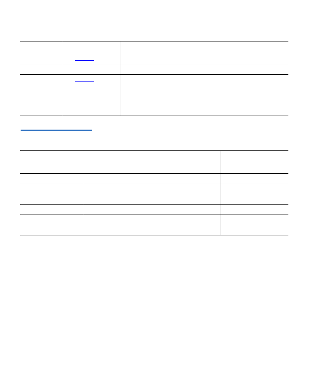
Field Value Description
Clocking See table 18. Clocking.
Chapter 4 SCSI Commands
INQUIRY Command (12h)
QAS See table 18
IUS See table 18
Version
Descriptors
Version descriptors
my vary by protocol
(Parallel SCSI, Fibre
Channel, and SAS)
Table 18 INQUIRY Command
Variance by Protocol
. Quick Arbitrate Supported.
. Information Units Supported.
Identifies the industry standards to which the drive conforms.
Note: As many version descriptors as apply for the drive are
returned.
Field Parallel SCSI Fibre Channel SAS
Addr16 1 0 0
Wbus16 100
Sync 100
CmdQue 101
Clocking 11b 00b 00b
QAS 100
IUS 100
DLT-S4 Interface Reference Guide 38
Page 73

Figure 8 Vendor-Specific
Inquiry Data Field — Data
Format
Chapter 4 SCSI Commands
INQUIRY Command (12h)
Vendor-Specific Inquiry Data Field 4
Figure 8 identifies the revision of tape drive subsystem components.
Bit
Byte
36 Product Family Released Firmware
37 Firmware Major Version Number
38 Firmware Minor Version Number
39 EEPROM Format Major Version Number
40 EEPROM Format Minor Version Number
41 Firmware Personality
42 Firmware Subpersonality
43 Vendor-Specific Subtype
44 Controller Hardware Version Number
45 Tape Drive EEPROM Version Number
46 Tape Drive Hardware Version Number
47 Media Loader Firmware Version Number
48 Media Loader Hardware Version Number
49 Media Loader Mechanical Version Number
7 6 5 4 3 2 1 0
50 Media Loader Present Flag
51 Library Present Flag
52 — 55 Module Revision
Note:
See Subsystem Components Revision Page (C1h) on page 52 for
information about an alternate method for accessing these same
drive subsystem components.
DLT-S4 Interface Reference Guide 39
Page 74

Chapter 4 SCSI Commands
INQUIRY Command (12h)
Table 19 Vendor-Specific
Inquiry Data Page — Field
Descriptions
Field Description
Product Family Indicates the data density of the tape drive. This field is set to a value of Dh
for the DLT-S4.
Released Firmware Differentiates between released and test versions of firmware. The Released
Firmware field combined with the Minor Version field, can be used to
determine the Code Version. Released customer code has no minor
firmware version number (byte 38 is set to 0). The following shows how to
determine the Code Version based on the Minor Version and the Released
Firmware Fields:
Code
Version
Released
Firmware
Minor
Version
V code 1 0
T code 1 Non-zero
X code 0 any
Version Number Fields These fields display the various version numbers in binary format, instead
of ASCII.
Firmware Personality Numeric indicator of firmware personality. Note that when set to 4,
indicates OEM family.
Firmware Subpersonality Indicates the variant of the firmware personality. Always set to 1, indicating
the primary firmware personality variant.
Vendor-Specific Subtype Product identification.
Media Loader Present Flag Set to zero to indicate there is no attached medium changer present.
Library Present Flag Set to 0 to indicate the drive has not detected the presence of a library
controller. Set to a non-zero value when communications has been
established with a tape automation system.
Module Revision A 4-byte ASCII string representing the revision level of the tape drive’s
module (the controller PCBA attached to the drive).
DLT-S4 Interface Reference Guide 40
Page 75

Chapter 4 SCSI Commands
INQUIRY Command (12h)
Vital Product Data Pages 4 The following subsections describe the Vital Product Data Pages for the
DLT-S4 tape drive.
Supported Vital Product Data Page (00h) 4
The Supported Vital Product Data Page provides a directory of the Vital
Product Data pages that the drive supports. The supported pages are:
• Supported Vital Product Data Page (00h)
• Unit Serial Number Page (80h)
• Device Identification Page (83h)
• Sequential-Access Device Capabilities Page (B0h)
• Manufacturer-assigned Serial Number Page (B1h)
• Firmware Build Information Page (C0h)
• Subsystem Components Revision Page (C1h).
Figure 9 Supported Vital
Product Data Pages — Data
Format
Bit
Byte
0 Peripheral Qualifier Peripheral Device Type
1 Page Code (00h)
2 Reserved
3 Page Length (07h)
4 Supported Vital Product Data Page (00h)
5 Unit Serial Number Page (80h)
6 Device Identification Page (83h)
7 Sequential-Access Device Capabilities Page (B0h)
8 Manufacturer-assigned Serial Number Page (B1h)
9 Firmware Build Information Page (C0h – Vendor Specific)
10 Subsystem Components Revision Page (C1h – Vendor Specific)
DLT-S4 Interface Reference Guide 41
7 6 5 4 3 2 1 0
Page 76

Unit Serial Number Page (80h) 4
Figure 10 shows the format of the Unit Serial Number Page the drive
returns.
Figure 10 Unit Serial Number
Page — Data Format
Bit
7 6 5 4 3 2 1 0
Byte
0 Peripheral Qualifier (0) Peripheral Device Type (01h)
1 Page Code (80h)
2 Reserved
3 Page Length (10h)
Chapter 4 SCSI Commands
INQUIRY Command (12h)
4 — 19 Serial Number
Table 20 Unit Serial Number
Page — Field Descriptions
Field Description
Serial Number The serial number given is the serial number of the
module or the drive, typically beginning with
“MX”, indicating the site of manufacture. If the
drive serial number is valid, it is reported;
otherwise, the module serial number is reported.
The serial number appears on the bar code label.
The drive returns the serial number in ASCII
format.
DLT-S4 Interface Reference Guide 42
Page 77

Figure 11 Device Identification
Page — Data Format
Chapter 4 SCSI Commands
INQUIRY Command (12h)
Device Identification Page (83h) 4
Figure 11 shows the format of the Device Identification Page the drive
returns.
Bit
Byte
0 Peripheral Qualifier (0) Peripheral Device Type (01h)
1 Page Code (83h)
2 Reserved
3 Page Length
4 — n Identification Descriptors
Table 21 Device Identification
Page — Field Descriptions
7 6 5 4 3 2 1 0
Field Description
Peripheral Qualifier Contains 000b.
Peripheral Device Type Contains 01h.
Page Code A value of 83h identifies this as the Device Identification page.
Page Length Indicates the size of the returned Device Identification page.
Identification
Descriptors
The drive always returns the Vendor-Unique Logical Unit Identifier and the
Logical Unit NAA Identifier. It may also return other identifiers. The
following identifiers are described in this section:
• Vendor-Unique Logical Unit Identifier
• Logical Unit NAA Identifier
• Port NAA Identifier
• Relative Target Port Identifier
DLT-S4 Interface Reference Guide 43
Page 78

Figure 12 Vendor-Unique
Logical Unit Identifier — Data
Format
Chapter 4 SCSI Commands
INQUIRY Command (12h)
Vendor-Unique Logical Unit Identifier 4
Figure 12 shows the format of the Vendor-Unique Logical Unit Identifier.
Bit
Byte
0 Protocol Identifier (0) Code Set (2h)
1 PIV (0) Reserved Association (0) Identifier Type (1)
2 Reserved
3 Identifier Length (40)
4 — 11
12 — 27
28 — 43
7 6 5 4 3 2 1 0
(MSB)
Vendor Identification
(MSB)
Product Identification
(MSB)
Serial Number
WORM
(LSB)
(LSB)
(LSB)
DLT-S4 Interface Reference Guide 44
Page 79

Table 22 Vendor-Unique
Logical Unit Identifier — Field
Descriptions
Field Description
Chapter 4 SCSI Commands
INQUIRY Command (12h)
Protocol
Set to 0.
Identifier
Code Set Set to 2h indicating the descriptor consists of ASCII printable characters.
PIV Protocol Identifier Valid. Set to 0, indicating that the value returned in the Protocol
Identifier field should be ignored.
Association Set to 0, indicating that the Identifier is associated with the logical unit.
Identifier Type Set to 1h indicating this identifier is of the T10 Vendor-Specific type.
WORM This would indicate that the drive can read and write WORM tapes.
Identifier Length Set to 40, indicating the remainder of the descriptor is 40 byte long.
Vendor
Identification
Product
Identification
The value in this field is left-aligned and set to “QUANTUM”. The remainder of the
field is filled with space characters.
This field is set to “DLT-S4”, left-aligned, and filled with space characters to the end
of the field.
Serial Number The serial number given is the serial number of the module or the drive, typically
beginning with “MX”, indicating the site of manufacture. If the drive serial number
is valid, it is reported; otherwise, the module serial number is reported. The serial
number appears on the bar code label. The drive returns the serial number in ASCII
format.
DLT-S4 Interface Reference Guide 45
Page 80

Figure 13 Logical Unit NAA
Identifier — Data Format
Chapter 4 SCSI Commands
INQUIRY Command (12h)
Logical Unit NAA Identifier 4
Figure 13 shows the format of the Logical Unit NAA Identifier.
Bit
Byte
0 Protocol Identifier (0) Code Set (1)
1 PIV (0) Reserved Association (0) Identifier Type (3h)
2 Reserved
3 Identifier Length (08h)
4 — 11
Table 23 Logical Unit NAA
Identifier — Field Descriptions
7 6 5 4 3 2 1 0
(MSB)
NAA Identifier (binary)
Field Description
Protocol Identifier Set to 0.
Code Set Set to 1h, indicating binary data.
PIV Set to 0, indicating that the value returned in the Protocol Identifier field
should be ignored.
(LSB)
Association Set to 0, indicating that the Identifier is associated with the logical unit.
Identifier Type Set to 3h indicating this identifier is of the NAA type.
Identifier Length Specifies the length in bytes of the Identifier field. If the Allocation Length
field of the CDB is too small to transfer the entire identifier, the Identifier
Length value is not adjusted to reflect the truncation.
NAA Identifier Contains the Name Address Authority (NAA) identifier for the logical unit.
DLT-S4 Interface Reference Guide 46
Page 81

Figure 14 Port NAA Identifier
— Data Format
Chapter 4 SCSI Commands
INQUIRY Command (12h)
Port NAA Identifier 4
Figure 14 shows the format of the Port NAA Identifier.
Bit
Byte
0 Protocol Identifier Code Set (1)
1 PIV (1) Reserved Association (1) Identifier Type (3)
2 Reserved
3 Identifier Length (08h)
4 — 11
Table 24 Port NAA Identifier —
Field Descriptions
7 6 5 4 3 2 1 0
(MSB)
NAA Identifier (binary)
Field Description
Protocol Identifier The drive returns 0 if the protocol is Fibre Channel, and 6h if the protocol is SAS.
This identifier type is not returned by devices using a parallel SCSI interface.
Code Set Set to 1h, indicating binary data.
PIV Set to 1, indicating that the value returned in the Protocol Identifier field is valid.
(LSB)
Association Set to 1h, indicating that the Identifier is associated with the port.
Identifier Type Set to 3h indicating this identifier is of the NAA type.
Identifier Length Specifies the length in bytes of the Identifier field. If the Allocation Length field of
the CDB is too small to transfer the entire identifier, the Identifier Length value is
not adjusted to reflect the truncation.
NAA Identifier Contains the Name Address Authority (NAA) identifier for the port.
DLT-S4 Interface Reference Guide 47
Page 82

Figure 15 Relative Target Port
Identifier — Data Format
Chapter 4 SCSI Commands
INQUIRY Command (12h)
Relative Target Port Identifier 4
Figure 15 shows the format of the Relative Target Port Identifier.
Bit
Byte
0 Protocol Identifier Code Set (1)
1 PIV (1) Reserved Association (1) Identifier Type (4)
2 Reserved
3 Identifier Length (04h)
4 — 5 Obsolete
6 — 7 Relative Target Port Identifier
Table 25 Relative Target Port
Identifier — Field Descriptions
7 6 5 4 3 2 1 0
Field Description
Protocol Identifier The drive returns 0h if the protocol is Fibre Channel, 1h if the protocol is Parallel
SCSI, and 6h if the protocol is SAS.
Code Set Set to 1h, indicating binary data.
PIV Set to 1h, indicating that the value returned in the Protocol Identifier field is valid.
Association Set to 1h, indicating that the Identifier is associated with the port.
Identifier Type Set to 4h indicating this identifier is of type Relative Target Port.
Identifier Length Specifies the length in bytes of the Identifier field. If the Allocation Length field of
the CDB is too small to transfer the entire identifier, the Identifier Length value is
not adjusted to reflect the truncation.
Relative Target Port
Value = 1 device has single port.
Identifier
DLT-S4 Interface Reference Guide 48
Page 83

Figure 16 Sequential-Access
Device Capabilities VPD Page
— Data Format
Chapter 4 SCSI Commands
INQUIRY Command (12h)
Sequential-Access Device Capabilities VPD Page (B0h) 4
Figure 16 and table 26 specify and describe the sequential-access device
capabilities VPD page. This page provides the application client with the
means to determine if the features specified in this page are supported by
the device server.
Bit
Byte
0 Peripheral Qualifier Peripheral Device Type
1 Page Code (B0h)
2 — 3
4 Reserved WORM (1)
5 — 7 Reserved
Table 26 Sequential-Access
Device Capabilities VPD Page
— Field Descriptions
7 6 5 4 3 2 1 0
(MSB)
Page Length (4)
Field Description
Peripheral Qualifier Contains 000b.
Peripheral Device
Contains 01h.
Type
Page Length The
PAG E L E N GTH field specifies the length of the following VPD page data. If the
allocation length value in the
INQUIRY command descriptor block is too small to
transfer all of the VPD page data, the page length is not adjusted to reflect the
truncation.
WORM The Write Once, Read Many (WORM) bit indicates if the device is capable of
supporting this mode. This bit is always set to 1.
(LSB)
DLT-S4 Interface Reference Guide 49
Page 84

Figure 17 ManufacturerAssigned Serial Number Page
— Data Format
Chapter 4 SCSI Commands
INQUIRY Command (12h)
Manufacturer-Assigned Serial Number Page (B1h) 4
Figure 17 and table 27 specify and describe the Manufacturer-Assigned
Serial Number Page.
Bit
Byte
0 Peripheral Qualifier Peripheral Device Type
1 Page Code (B1h)
2 Reserved
3 Page Length (10h)
4 — 19
Table 27 ManufacturerAssigned Serial Number Page
— Field Descriptions
7 6 5 4 3 2 1 0
Manufacturer Serial Number
Field Description
Peripheral Qualifier Contains 000b.
Peripheral Device
Contains 01h.
Type
Page Code A value of B1h identifies this as the Manufacturer-Assigned Serial Number page.
Page Length Contains 10h that indicates the size of the returned Manufacturer-Assigned Serial
Number page.
Manufacturer Serial
Number
DLT-S4 Interface Reference Guide 50
The Manufacturer Serial Number field contains right-aligned ASCII data that is
the manufacturer assigned serial number.
Page 85

Figure 18 Firmware Build
Information Page — Data
Format
Chapter 4 SCSI Commands
INQUIRY Command (12h)
Firmware Build Information Page (C0h) 4
Figure 18 shows the format of the Firmware Build Information page the
drive returns.
Bit
Byte
0
1
2
3
4 — 7
8 — 11
12 — 15
16 — 19
20 — 43
Table 28 Firmware Build
Information Page — Field
Descriptions
7 6 5 4 3 2 1 0
Peripheral Qualifier Peripheral Device Type
Field Description
Page Code (C0h)
Reserved WORM
Page Length (28h)
Servo Firmware Revision
Servo Firmware Checksum
Servo EEPROM Checksum
Controller Firmware Checksum
Controller Firmware Build Date
WORM The Write Once, Read Many (WORM) bit indicates if the device is
capable of supporting this mode. This bit is always set to 1.
Servo Firmware Revision Contains the revision number of the servo firmware.
Checksum The Servo Firmware, Servo EEPROM, and
READ / WRITE Firmware
checksums are binary numbers used for positive firmware and
EEPROM identification.
Controller Firmware Build
Date
DLT-S4 Interface Reference Guide 51
Firmware Build Date. An ASCII string in DD-MM-YYYY HH:MM:SS
format.
Page 86

Figure 19 Subsystem
Components Revision Page —
Data Format
Chapter 4 SCSI Commands
INQUIRY Command (12h)
Subsystem Components Revision Page (C1h) 4
Figure 19 identifies the revision of tape drive subsystem components.
Bit
Byte
0 Peripheral Qualifier Peripheral Device Type
1 Page Code (C1h)
2 Reserved
3 Page Length (39h)
4 Product Family Released Firmware
5 Firmware Major Version Number
6 Firmware Minor Version Number
7 EEPROM Format Major Version Number
8 EEPROM Format Minor Version Number
9 Firmware Personality
10 Firmware Subpersonality
11 Vendor-Specific Subtype
12 Controller Hardware Version Number
13 Tape Drive EEPROM Version Number
14 Tape Drive Hardware Version Number
7 6 5 4 3 2 1 0
15 Media Loader Firmware Version Number
16 Media Loader Hardware Version Number
17 Media Loader Mechanical Version Number
18 Media Loader Present Flag
19 Library Present Flag
20 — 23 Module Revision
24 — 43 Unit Serial Number
DLT-S4 Interface Reference Guide 52
Page 87

Chapter 4 SCSI Commands
INQUIRY Command (12h)
Table 29 Subsystem
Components Revision Page —
Field Descriptions
Field Description
Product Family Indicates the data density of the tape drive. This field is set to a value of Dh.
Released
Firmware
Differentiates between released and test versions of firmware. When set to 1,
indicates released code (Vxxx); when set to 0, indicates field test code (Txxx).
Released code has no minor firmware version number (byte 38 is set to 0). For
tracking purposes, field test and engineering versions of code have non-zero minor
firmware version numbers.
Version Number
Fields
Firmware
Personality
Firmware
Subpersonality
Vendor-Specific
These fields display the various version numbers in binary format, instead of
ASCII.
Numeric indicator of firmware personality. Note that when set to 4, indicates OEM
family.
Indicates the variant of the firmware personality. Always set to 1, indicating the
primary firmware personality variant.
Product identification.
Subtype
Media Loader
When set to 0, indicates no loader present. Non-zero indicates loader is present.
Present Flag
Library Present
When set to 0, indicates no library present. Non-zero indicates library is present.
Flag
Module Revision A 4-byte ASCII string representing the revision level of the tape drive’s module (the
controller PCBA attached to the drive).
Unit Serial
Drive’s serial number; matches what is shown on the exterior of the drive chassis.
Number
DLT-S4 Interface Reference Guide 53
Page 88

Chapter 4 SCSI Commands
LOAD UNLOAD Command (1Bh)
LOAD UNLOAD Command (1Bh) 4
The LOAD UNLOAD command instructs the DLT-S4 tape drive to load or
unload the tape inside the data cartridge. If no data cartridge is in the
Figure 20 LOAD UNLOAD
Command Descriptor Block
Data Format
drive, the
with the Sense Key set to
LOAD UNLOAD command with the Immediate bit set and then it receives
another command that requires tape motion or if it receives a
READY
Sense Key set to
Before executing the
cached write data to the tape.
—
LOAD UNLOAD command returns a CHECK CONDITION status
NOT READY. Likewise, if the drive receives a
TEST UNIT
command, the drive returns a CHECK CONDITION status with the
NOT READY.
LOAD UNLOAD command, the drive writes any
Bit
Byte
0 Operation Code (1Bh)
1 Reserved Immed
2 — 3 Reserved
4 Reserved Hold EOT ReTen Load
5 Control
DLT-S4 Interface Reference Guide 54
7 6 5 4 3 2 1 0
Page 89

Chapter 4 SCSI Commands
LOAD UNLOAD Command (1Bh)
Table 30 LOAD UNLOAD
Command Descriptor Block
Field Descriptions
—
Field Description
Immed Immediate. When set to 1, the drive returns status as soon as the operation starts. When set
to 0, the drive returns status after the operation has completed.
Hold See table 31
.
EOT End of Tape. The drive ignores this bit unless both the EOT and Load bits are set to 1, then
the drive returns
CHECK CONDITION status with Sense Key set to ILLEGAL REQUEST.
ReTen Retension. Ignored. Retension operations are not needed.
Load See table 31
Table 31 HOLD and LOAD —
Field Descriptions
.
HOLD LOAD Description
0 0 The tape is unloaded and the cartridge is ejected. When the
the
LOAD bit is set to 0, the tape is unloaded and the cartridge is ejected.
0 1 The tape is and positioned for access. When set to 0 and the
HOLD bit is set to 0 and
LOAD bit is set to one,
the tape is loaded for medium access.
1 0 The tape is unloaded, but not ejected. When the HOLD bit is set to 1 and the
LOAD
bit is set to 0, the tape is unloaded from the device but not ejected to allow the
operator access to the cartridge.
1 1 The tape is seated, but not loaded. When the
HOLD bit set to 1 and the LOAD bit is
also set to 1, the tape is loaded to the point where the MAM is accessible but the
medium is not positioned for access.
DLT-S4 Interface Reference Guide 55
Page 90

Chapter 4 SCSI Commands
LOCATE Command (2Bh)
LOCATE Command (2Bh) 4
The LOCATE command performs high-speed positioning to a specified
block address. Use the
address associated with the current position on tape. Then use the
LOCATE command to position the tape at the same logical position for
high-performance restore operations of particular blocks of data.
Figure 21 LOCATE Command
Descriptor Block — Data
Format
READ POSITION command to obtain the block
Bit
Byte
0 Operation Code (2Bh)
1 Reserved BT CP Immed
2 Reserved
3 — 6
7 Reserved
8 Partition
9 Control
Table 32 LOCATE Command
Descriptor Block
Descriptions
7 6 5 4 3 2 1 0
(MSB)
Logical Object Identifier
(LSB)
— Field
Field Description
BT Block Type. The drive ignores this bit.
CP Change Partition. Must set to 0.
Immed Immediate. When set to 1, the drive returns status as soon as the operation
starts. When set to 0, the drive returns status after the operation has completed.
Logical Object Identifier Specifies the Logical Object Identifier to which the drive positions the medium.
Partition Not applicable; the drive ignores this bit (see CP field).
DLT-S4 Interface Reference Guide 56
Page 91

Chapter 4 SCSI Commands
LOG SELECT Command (4Ch)
LOG SELECT Command (4Ch) 4
The LOG SELECT command allows the host to manage statistical
information the DLT-S4 tape drive maintains about its own hardware
parameters and about the installed tape medium. Read the description of
the LOG SENSE Command (4Dh)
about log page format, parameters, and supported pages.
Figure 22 LOG SELECT
Descriptor Block — Data
Format
Bit
7 6 5 4 3 2 1 0
Byte
0 Operation Code (4Ch)
on page 66; it provides information
1 Reserved PCR SP
2 PC Reserved
3 — 6 Reserved
(MSB)
7 — 8
9 Control
DLT-S4 Interface Reference Guide 57
Parameter List Length
(LSB)
Page 92

Chapter 4 SCSI Commands
LOG SELECT Command (4Ch)
Table 33 LOG SELECT
Command Descriptor Block —
Field Descriptions
Field Description
PCR Parameter Code Reset. If this bit is set to 1 and the Parameter List Length field is
set to 0, all accumulated values of page codes 2, 3, and 0C are set to 0 and all
threshold values are set to default. If PCR is set to 1 and the Parameter List Length
field is set to a non-zero value, the drive terminates the command with
CONDITION
(ASC) set to
status, Sense Key set to ILLEGAL REQUEST, and Additional Sense Code
INVALID FIELD IN CDB.
CHECK
SP Save Parameters. Must be set to 0.
PC Page Control. Defines the type of parameter values to be selected:
Code Types of Parameter Value
00b Current Threshold Values
01b Current Threshold Values
10b Default Threshold Values
11b Default Threshold Values
When the PC field is set to 10b and the Parameter List Length field is set to 0, all
Current Threshold Values are reset to the Default Threshold Values. When the PC
field is set to 11b and the Parameter List Length field is set to 0, all Current
Cumulative Values are reset to the Default Cumulative Values. This is equivalent
to clearing all log pages that can be cleared.
Note: The drive ignores the PC field value if the PCR bit is set to 1.
Parameter List
Length
Specifies the length, in bytes, of the LOG SELECT parameter list to be transferred
from the initiator to the drive during
DATA OUT.
A Parameter List Length of 0 indicates that no data is to be transferred. This
condition is not considered an error.
DLT-S4 Interface Reference Guide 58
Page 93

Chapter 4 SCSI Commands
LOG SELECT Command (4Ch)
Overview—LOG SELECT
Command Descriptor
Block Errors
Operation of LOG SELECT
The following conditions constitute errors that the drive detects in
relation to the CDB. If the drive detects one of the conditions listed, it will
return
4
CHECK CONDITION with the Sense Key set to ILLEGAL REQUEST
and the Additional Sense Code set to INVALID FIELD IN CDB.
The conditions that constitute errors are:
• PCR bit is set to 1; Parameter List Length field is not set to 0.
• Both the PCR and SP bits are set to 1.
• A Parameter List Length that would cause a parameter within a valid
page to be truncated or otherwise incompletely initialized.
The LOG SELECT command allows the initiator to modify and initialize
parameters within the logs the drive supports.
4
The two ways to initialize the log parameters are:
1 Set the PCR bit to 1 in the
LOG SELECT CDB; this clears all
parameters.
2 Specify the log page and parameter values as the log parameters to
clear individual pages. The following pages can be cleared using this
method:
Table 34 LOG SELECT Pageclearing Codes
Page Code Page Description
02h Write Error Count Page
03h Read Error Count Page
0Ch Sequential Access Device Page
38h General Purpose Non-Volatile Log Page
Note: If an initiator sends multiple pages, it must send them in
ascending order according to page code. Otherwise, the drive
terminates the command with a
Sense Key set to
Code set to
ILLEGAL REQUEST, and Additional Sense
INVALID FIELD IN PARAMETER LIST. The drive
CHECK CONDITION status,
returns the same status if an unsupported page code appears
in any header or if the specified page cannot be cleared.
DLT-S4 Interface Reference Guide 59
Page 94

Chapter 4 SCSI Commands
LOG SELECT Command (4Ch)
LOG SELECT Log Page
Format
Each log page begins with a 4-byte header followed by n number of log
parameter blocks—one block for each parameter code. Each block, except
4
for parameter code 05h, comprises 8 bytes. The parameter block for page
code 05h is 12 bytes.
Figure 23 LOG SELECT Log
Page — Data Format
Bit
Byte
0 Page Code
1 Reserved
7 6 5 4 3 2 1 0
(MSB)
2 – 3
4 Log Parameter (First)
x + 3 Length (x)
Page Length (n – 3)
Log Parameters
(LSB)
.
.
n — y + 1 Log Parameter (Last)
n Length (y)
Table 35 LOG SELECT Log
Page Header — Field
Descriptions
Field Description
Page Code Specifies the log page to which this
LOG SELECT
command is directed.
Page Length Specifies the total number of bytes contained in this
log page, not including the 4 bytes that make up the
header.
Log Parameters Use one block for each parameter code.
DLT-S4 Interface Reference Guide 60
Page 95

Figure 24 LOG SELECT Log
Page — Parameters Format
Chapter 4 SCSI Commands
LOG SELECT Command (4Ch)
Bit
Byte
7 6 5 4 3 2 1 0
(MSB)
0 — 1
2 DU DS TSD ETC TMC LBIN LP
3 Parameter Length (n – 3)
Parameter Code
(MSB)
4 — n
Table 36 LOG SELECT Log
Parameters — Field
Descriptions
Parameter Value
Field Description
Parameter Code Parameter codes supported for the
READ / WRITE error counter pages:
(LSB)
(LSB)
Code Description
0000h Errors corrected without substantial delays
0001h Errors corrected with possible delays
0002h Total read / write errors
0003h Total read / write errors
0004h Total times correction algorithm processed. Always 0 for write errors only.
0005h Total bytes processed
0006h Total uncorrected errors
8000h
DLT-S4 Interface Reference Guide 61
WRITE errors since last READ (page 02) or
READ errors since last WRITE (page 03)
Page 96

Field Description
Chapter 4 SCSI Commands
LOG SELECT Command (4Ch)
Parameter Code
(continued)
8001h Total raw write error flags
8002h Total dropout error count
8003h Total servo tracking errors
9000h-
Without substantial delay errors by channel
900Fh
9080h908Fh
Note: Parameter codes 00h, 01h, and 04h always have a value of 0. Parameter value for 05h
Write only: Possible delay errors assignable to specific channels
Read only: Raw sub-block read errors by channel
Note: Many of these errors are write, not read, errors and are not to be included
in read error-rate calculations. If these errors are used to try to identify bad
channels, the bad channel may be on either the writing or reading drive.
is eight bytes; the Parameter Length field is set to 8.
DU Disable Update. This bit is not defined for LOG SELECT; the drive ignores any value
in DU.
DS Disable Save. DS and Target Save Disable (TSD) must be set to 1.
TSD Target Save Disable. TSD and DS must be set to 1.
ETC Enable Threshold Comparison. When set to 1, the drive performs a comparison with
threshold values once the cumulative value is updated. Comparison criteria are
defined in Threshold Met Criteria (TMC). If the comparison is met and the RLEC bit
of
MODE SELECT / SENSE Control Page 0Ah is set to 1, the drive generates a UNIT
ATTENTION
THRESHOLD CONDITION MET. If the RLEC bit is 0 and the comparison is met, the
drive does not generate a
for all initiators. The drive sets the Additional Sense Code to
UNIT ATTENTION.
TMC Threshold Met Criteria. Once the criteria specified in this field are met, the ETC bit is
1, and the RLEC bit in the
generates a
UNIT ATTENTION for all initiators.
MODE SENSE / SELECT Control Page is set to 1, the drive
The criteria for comparison are:
Code Basis of Comparison
00b Every update of the cumulative value
01b Cumulative value equal to threshold value
10b Cumulative value not equal to threshold value
11b Cumulative value greater than threshold value
DLT-S4 Interface Reference Guide 62
Page 97

Field Description
Chapter 4 SCSI Commands
LOG SELECT Command (4Ch)
TMC (continued)
• The Default Threshold Values are the maximum values that each parameter can
attain.
• The Current Cumulative Values are the values computed since the last reset of the
tape drive by power-cycle,
TARGET RESET, SCSI RESET, or FCP TARGET RESET.
• The Default Cumulative Values are the values to which each parameter is
initialized at a reset condition. Default value is 0.
• By default, Current Threshold Values are set to Default Threshold Values.
• Note that all types of parameter values are changeable using
LOG SELECT.
LBIN List Binary. Must be set to 0.
LP List Parameter. Always set this bit to 0 to indicate that parameter codes are treated as
data counters.
Parameter Length Specifies the number of bytes in the parameter value.
Parameter Value Indicates the actual value of this log parameter.
General Purpose Non-Volatile Log Page (38h)
Log page 38h provides access to a 64 byte non-volatile buffer in the tape
drive for general purpose use. The log page contains one 64 byte
parameter with a Parameter Code setting of 0. The 64 bytes in the
4
Parameter Value field are stored in device non-volatile memory and are
returned when a
LOG SENSE command requests log page 38h.
Figure 25 General Purpose
Non-Volatile LOG SELECT
Page — Header Format
Bit
Byte
0 Page Code (38h)
1 Reserved
7 6 5 4 3 2 1 0
(MSB)
2 – 3
DLT-S4 Interface Reference Guide 63
Page Length
(LSB)
Page 98

Chapter 4 SCSI Commands
LOG SELECT Command (4Ch)
Table 37 General Purpose
Non-Volatile LOG SELECT
Header — Field Descriptions
Field Description
Page Code Echoes the page code specified in the
LOG SELECT CDB.
Page Length Specifies the total number of bytes contained in this log
page, not including the 4 bytes that make up the header.
Figure 26 General Purpose
Non-Volatile LOG SELECT
Page — Parameter Format
Bit
Byte
7 6 5 4 3 2 1 0
(MSB)
0 — 1
2 DU DS TSD ETC TMC LBIN LP
3 Parameter Length (40h)
Parameter Code
(MSB)
4 — 67
Parameter Value
(LSB)
(LSB)
DLT-S4 Interface Reference Guide 64
Page 99

Chapter 4 SCSI Commands
LOG SELECT Command (4Ch)
Table 38 General Purpose
Non-Volatile LOG SELECT
Page — Field Descriptions
Field Description
Parameter Code Parameter code supported for this page. Must be 0.
Parameter
Control Byte
Bit Value Description
DU 1 Disable Update.
DS 0 Disable Save.
TSD 0 Target Save Disable.
ETC 0 Enable Threshold Comparison.
TMC 0 Threshold Met Criteria.
LBIN 0 List Binary.
LP 1 List Parameter.
Parameter Length Specifies the number of bytes in the parameter value. Must be 40h.
Parameter Value Indicates the actual value of this log parameter.
Error Detection Summary in LOG SELECT Pages
The host issues a LOG SENSE command to initialize host-resident
software that allows determination of:
4
• The log pages the drive uses.
• The parameter codes and length of each parameter.
The following conditions constitute errors in the parameter block that
cause the drive to return
ILLEGAL REQUEST and Additional Sense Code set to INVALID FIELD IN
PARAMETER LIST
:
CHECK CONDITION status with Sense Data set to
• The drive receives a page header with unsupported page codes.
• An incorrect log page length is specified in the page header.
• An illegal parameter code is contained in a valid page code.
• Parameter codes for a supported page are not sent in ascending
order.
• The parameter control byte is set to an invalid value for the parameter
code.
DLT-S4 Interface Reference Guide 65
Page 100

Chapter 4 SCSI Commands
LOG SENSE Command (4Dh)
LOG SENSE Command (4Dh) 4
The LOG SENSE command allows the host to retrieve statistical
information the tape drive maintains about its own hardware parameters
or about the installed tape medium. This command complements the
SELECT
Figure 27 LOG SENSE
Command Descriptor Block —
Data Format
Bit
7 6 5 4 3 2 1 0
Byte
0 Operation Code (4Dh)
1 Reserved PPC SP (0)
command.
LOG
2 PC Page Code
3 — 4 Reserved
(MSB)
5 — 6
(MSB)
7 — 8
9 Control
DLT-S4 Interface Reference Guide 66
Parameter Pointer
(LSB)
Allocation Length
(LSB)
 Loading...