

Page 1

®
DLT2000/DLT2500/DLT2700
Cartridge Tape Subsystem
Product Manual
Date: 19 January 96
Order Number: 81-109132-03
Page 2

Quantum reserves the right to make changes and improvements to its products, without
incurring any obligation to incorporate such changes or improvements in units previously sold
or shipped.
You can request Quantum publications from your Quantum Sales Representative, or order them
directly from Quantum.
Publication Number: 81-109132-03
SERVICE CENTERS
Quantum Service Center
715 Sycamore Avenue
Milpitas, California 95035
Phone (408) 894-4000
Fax: (408) 894-3218
Quantum Gmbh
Genferstrasse 4B
60437 Frankfurt am Main 56
Germany
Phone: (49) 69-509-1080
Fax: (49) 69-509-10891
Quantum Asia-Pacific Pte.
Ltd.
50 Tagore Lane #b1-04
Singapore, 2678
Phone: (65) 450-9333
Fax (65) 452-2544
CompacTape is a trademark of Quantum Corporation.
DLT is a trademark of Quantum Corporation.
Copyright
1996 by Quantum Corporation. All rights reserved. Printed in USA.
Page 3

The following FCC Notice applies to the DLT2000 drive:
FCC NOTICE: This equipment has been tested and found to comply with the limits for a
Class B digital device, pursuant to Part 15 of the FCC rules. These limits are designed to
provide reasonable protection against harmful interference in residential installation. Any
changes or modifications made to this equipment may void the user’s authority to operate this
equipment.
This equipment generates, uses, and radiates radio frequency energy and, if not installed and
used in accordance with the instructions, may cause harmful interference to radio
communications. However, there is no guarantee that interference will not occur in a particular
installation. If this equipment does cause harmful interference to radio or television reception,
which can be determined by tuning the equipment off and on, the user is encouraged to try to
correct the interference by one or more of the following measures:
1. Reorient or relocate the receiving antenna.
2. Increase the separation between the equipment and receiver.
3. Connect the equipment into an outlet on a circuit different from that to which the receiver
is connected.
4. Consult the dealer or an experienced radio/TV technician for help. The shielded
interconnect cable shipped with the unit should not be altered or modified in any way. The
unit shipped without a shielded interconnect cable must use a shielded interconnect cable.
The user may find the following booklet prepared by the Federal Communications Commission
helpful: How to Identify and Resolve Radio-TV Interference Problems. This booklet is
available from the U.S. Government Printing Office, Washington D.C., 20402. Stock No. 00400398-5.
All external I/O cables connecting to this unit need to be shielded. See the User Manual or
installation instructions for more options.
This digital apparatus does not exceed the Class B limits for radio noise emissions set out in
the radio interference regulations of the Canadian Department of Communications.
This equipment is in the 2nd Class Category (information equipment to be used in a residential
area or an adjacent area thereto) and conforms to the standards set by the Voluntary Control
Council For Interference by Data Processing Equipment and Electronic Office Machines aimed
at preventing radio interference in such residential area.
This equipment meets or exceeds requirements for safety in the U.S. (UL 1950), Canada (CSA
C22.2 N0. 950) and Europe (EN60950/IEC 950) requirements, and is certified to bear the GS
mark by TUV.
Page 4

The following FCC Notice applies to DLT2500 and DLT2700 mini-library:
FCC NOTICE: This equipment has been tested and found to comply with the limits for a
Class A device, pursuant to Part 15 of the FCC Rules. These limits are designed to provide
reasonable protection against harmful interference when the equipment is operated in a
commercial environment. This equipment generates, uses and can radiate radio frequency
energy and, if not installed and used in accordance with the instruction manual, may cause
harmful interference to radio communications. Any changes or modifications made to this
equipment may void the user’s authority to operate this equipment. Operation of this equipment
in a residential area may cause interference in which case the user at his own expense will be
required to take whatever measures may be required to correct the interference. The shielded
interconnect cable shipped with the unit should not be altered or modified in any way. The unit
shipped without a shielded cable must use a shielded interconnect cable.
Warning! This is a Class A product. In a domestic environment this product may cause radio
interference in which case the user may be required to take adequate measures.
Achtung! Dieses ist ein G erat der Funksto rgenzwertklasse A. In Wohnbereicghen konnen bei
Betrieb dieses Gerate s Runfunkstorungen auftreten, in welchen Fallen der Benutzer fur
entsprechende GengenmaBnahmen verantwortlich ist.
Attention! Ceci est un produit de Classe A. Dans un environment do mesti que, ce pro duit
risque de creer des interferences radioelectriques, il appartiendra alors a l'utilisateur de prendre
les mesures specifiques appropriees.
Page 5

Table of Contents
. CHAPTER 1: OVERVIEW AND FEATURES OF THE DLT2000/DLT2500/DLT2700
PRODUCT
1.1 I
N THIS CHAPTER.............................................................................................................1-1
1.2 P
RODUCT OVERVIEW.......................................................................................................1-1
1.3 F
AST DATA TRANSFER RATE ...........................................................................................1-2
1.4 H
IGH-CAPACITY............................................................................................................... 1-2
1.5 C
OMPACTION...................................................................................................................1-2
1.6 S
TRONG MEDIA................................................................................................................ 1-2
1.7 C
OMPATIBILITY................................................................................................................1-2
1.8 F
IRMWARE UPDATE CAPABILITY......................................................................................1-3
1.9 E
MBEDDED DIAGNOSTICS ................................................................................................1-3
. CHAPTER 2: INSTALLING AND CONFIGURING THE DLT2000
2.1 I
N THIS CHAPTER.............................................................................................................2-1
2.2 P
REPARE FOR THE INSTALLATION ....................................................................................2-1
2.2.1 Before You Start.....................................................................................................2-1
2.2.2 Installation Setup....................................................................................................2-2
2.2.3 Site Setup................................................................................................................2-2
2.2.4 Site Guidelines........................................................................................................2-2
2.3 I
NSTALL THE SUBSYSTEM ................................................................................................2-4
2.4 C
ONFIGURE THE DLT2000 TABLETOP.............................................................................2-4
2.4.1 Configuration Guidelines........................................................................................2-4
2.4.2 DISABLE PARITY Checking................................................................................2-5
2.4.3 Changing the SCSI ID............................................................................................2-5
2.5 C
ONNECT THE CABLES.....................................................................................................2-5
2.5.1 Examine the DLT2000 Rear Panel.........................................................................2-6
2.5.2 Connect the SCSI Signal Cable..............................................................................2-6
2.5.3 Terminate the SCSI Bus.........................................................................................2-7
2.5.4 Connect the Power Cord.........................................................................................2-7
2.6 T
EST THE INSTALLATION..................................................................................................2-8
2.6.1 Run POST...............................................................................................................2-8
2.6.2 What to Do after POST ..........................................................................................2-9
2.7 DLT2000 T
ROUBLESHOOTING CHART...........................................................................2-10
. CHAPTER 3: CONFIGURING AND OPERATING THE DLT2000
3.1 I
N THIS CHAPTER.............................................................................................................3-1
3.2 B
EFORE YOU INSTALL THE DLT2000 DRIVE...................................................................3-1
3.2.1 Disabling Parity Checking......................................................................................3-2
DLT2000/DLT2500/DLT2700 Cartridge Tape Subsystem-v
Page 6

Table of Contents
3.2.2 Changing the SCSI ID ............................................................................................3-4
3.2.3 Setting the TRM ENB (Single-ended only)/TRM PWR Jumpers...........................3-5
3.2.4 Locating the SCSI Cable and Power Connectors....................................................3-6
3.3 S
ELECTING DENSITY ........................................................................................................3-7
3.4 O
VERVIEW OF THE FRONT PANEL...................................................................................3-10
3.5 D
ESCRIPTION OF CONTROLS AND INDICATORS...............................................................3-11
3.5.1 Beeper...................................................................................................................3-11
3.5.2 Unload Button.......................................................................................................3-11
3.5.3 Cartridge Insert/Release Handle...........................................................................3-11
3.5.4 Indicator Action during Power-On Self Test and Operation.................................3-12
3.6 D
ESCRIPTION OF THE TAPE CARTRIDGE .........................................................................3-17
3.6.1 Cartridge Write-Protect Switch.............................................................................3-17
3.6.2 Data Protection.....................................................................................................3-19
3.7 L
OADING A CARTRIDGE..................................................................................................3-20
3.7.1 Tape in Use...........................................................................................................3-22
3.8 U
SING THE CLEANING TAPE CARTRIDGE........................................................................3-23
3.9 U
NLOADING A CARTRIDGE .............................................................................................3-24
3.10 P
RESERVING CARTRIDGES............................................................................................3-26
. CHAPTER 4: CONFIGURING AND OPERATING THE DLT2500 MINI-LIBRARY
4.1 I
N THIS CHAPTER.............................................................................................................4-1
4.2 I
NTRODUCTION TO THE MINI-LIBRARY.............................................................................4-6
4.3 C
ONFIGURE THE DLT2500...............................................................................................4-7
4.3.1 Configuration guidelines.........................................................................................4-7
4.3.2 Connecting the SCSI Signal Cable ......................................................................... 4-7
4.4 I
NSTALLATION TESTING....................................................................................................4-8
4.4.1 Run POST...............................................................................................................4-8
4.4.2 What to Do after POST ..........................................................................................4-8
4.5 O
PERATOR CONTROL PANEL............................................................................................4-9
4.6 K
EY LOCK......................................................................................................................4-13
4.6.1 OCP, locked or OCP, Disabled.............................................................................4-13
4.6.2 OCP, Unlocked or Enabled...................................................................................4-13
4.6.3 SCSI ID, setting....................................................................................................4-13
4.7 S
ELECTING DENSITY.......................................................................................................4-14
4.7.1 Front panel, density select....................................................................................4-15
4.7.2 Host selection, density..........................................................................................4-16
4.7.3 Native default, density..........................................................................................4-16
4.8 D
EFAULT OPERATING MODES .........................................................................................4-17
4.8.1 Mode, normal........................................................................................................4-17
4.8.2 Density Select Mode.............................................................................................4-18
4.8.3 SCSI ID Select Mode ...........................................................................................4-19
4.8.4 Code update mode................................................................................................4-19
4.9 D
ESCRIPTION OF THE TAPE CARTRIDGE .........................................................................4-20
vi-DLT2000/DLT2500/DLT2700 Cartridge Tape Subsystem
Page 7

Table of Contents
4.9.1 Tape Cartridge, positioning the write-protect switch............................................4-20
4.9.2 Data protection..................................................................................................... 4-21
4.10 D
ESCRIPTION OF THE MAGAZINE..................................................................................4-22
4.10.1 Insert cartridge, magazine...................................................................................4-23
4.10.2 Removing cartridge ............................................................................................4-25
4.10.3 Magazine, removing from mini-library...............................................................4-26
4.10.4 Magazine, installing............................................................................................4-26
4.10.5 Selecting a Cartridge from the Magazine ...........................................................4-27
4.10.6 Loading cartridge into the Drive.........................................................................4-27
4.10.7 Unloading cartridge from the drive ....................................................................4-28
4.10.8 Opening the Magazine Door...............................................................................4-28
4.11 W
HEN TO USE THE CLEANING TAPE CARTRIDGE .........................................................4-29
. CHAPTER 5: CONFIGURING AND OPERATING THE DLT2700 MINI-LIBRARY
5.1 I
N THIS CHAPTER.............................................................................................................5-1
5.2 I
NTRODUCTION TO THE MINI-LIBRARY ............................................................................5-1
5.3 C
ONFIGURING THE DLT2700...........................................................................................5-2
5.3.1 Configuration Guidelines........................................................................................5-3
5.3.2 Disable Parity Checking.........................................................................................5-3
5.3.3 Change the SCSI ID ...............................................................................................5-3
5.4 M
ODE SELECT KEY..........................................................................................................5-5
5.4.1 OCP Disabled Mode...............................................................................................5-5
5.4.2 Automatic Mode.....................................................................................................5-7
5.4.3 Manual Mode .........................................................................................................5-7
5.4.4 Service Mode..........................................................................................................5-8
5.5 S
ELECTING DENSITY........................................................................................................5-9
5.6 O
PERATOR CONTROL PANEL..........................................................................................5-12
5.7 P
OWER-ON PROCESS .....................................................................................................5-15
5.8 S
LOT SELECT, LOAD/UNLOAD .......................................................................................5-17
5.8.1 Selecting a Cartridge ............................................................................................5-17
5.8.2 Loading the Cartridge...........................................................................................5-17
5.8.3 Unloading the Cartridge.......................................................................................5-18
5.8.4 Opening the Receiver...........................................................................................5-19
5.9 M
AGAZINE .....................................................................................................................5-20
5.9.1 Inserting a Cartridge.............................................................................................5-20
5.9.2 Removing a Cartridge from the Magazine............................................................ 5-23
5.9.3 Removing the Magazine from the Receiver..........................................................5-23
5.9.4 Installing the Magazine into the Receiver.............................................................5-23
. CHAPTER 6: TROUBLESHOOTING GUIDE FOR THE DLT2500/DLT2700 MINI-
LIBRARY
6.1 I
N THIS CHAPTER.............................................................................................................6-1
6.2 C
ONDITIONS NECESSARY FOR BUTTON OPERATION.........................................................6-1
DLT2000/DLT2500/DLT2700 Cartridge Tape Subsystem-vii
Page 8

Table of Contents
6.3 BACKUP OPERATION FAILURE..........................................................................................6-3
6.4 A
VOIDING BASIC PROBLEMS............................................................................................6-4
6.5 DLT2500 E
RROR CONDITIONS ........................................................................................6-5
6.5.1 DLT2500 Magazine Error......................................................................................6-5
6.5.1.1 DLT2500 Clearing a Magazine......................................................................6-5
6.5.2 DLT2500 Loader Error Description.......................................................................6-5
6.5.3 DLT2500 Drive Error Description.........................................................................6-5
6.5.4 DLT2500 Controller Error Description..................................................................6-5
6.5.5 DLT2500 Unknown Error Description...................................................................6-6
6.5.5.1 DLT2500 Clearing a Loader, Drive, Controller, or Unknown.......................6-6
6.6 DLT2700 E
RROR CONDITIONS ........................................................................................6-6
6.6.1 DLT2700 Magazine Fault Cases............................................................................6-6
6.6.2 DLT2700 Loader Fault Description.......................................................................6-8
6.7 P
OWER PROBLEMS...........................................................................................................6-8
. CHAPTER 7: FIRMWARE UPDATE
7.1 I
N THIS CHAPTER.............................................................................................................7-1
7.2 DLT2000 F
IRMWARE UPDATE OVERVIEW.......................................................................7-1
7.2.1 Before Doing the Procedure...................................................................................7-2
7.3 C
REATING A FIRMWARE UPDATE TAPE ............................................................................7-4
7.3.1 On UN*X Systems..................................................................................................7-4
7.4 F
IRMWARE UPDATE PROCEDURE .....................................................................................7-5
7.4.1 Updating the Firmware on DLT2000 (Drive Only Configuration).........................7-5
7.4.2 Updating the Firmware on the DLT2500 (Drive and Loader Configuration).......7-10
7.4.3 Updating the Firmware on the DLT2700 (Drive and Loader Configuration).......7-14
. CHAPTER 8: DLT2000 SCSI INTERFACE
8.1 O
VERVIEW .......................................................................................................................8-1
8.2 G
ENERAL SCSI BUS OPERATIONS....................................................................................8-1
8.2.1 Data Transfer..........................................................................................................8-1
8.2.2 Initiator/Target Operations .....................................................................................8-2
8.2.3 SCSI IDs and Logical Unit Numbers (LUNs) ........................................................8-2
8.2.4 Unit Attention Condition........................................................................................8-3
8.2.5 Behavior Around Power-On and SCSI Bus Reset..................................................8-3
8.2.6 Data Cache and Tape Write Interaction..................................................................8-4
8.2.7 Other SCSI Functionality........................................................................................8-4
8.2.8 Bus Phases..............................................................................................................8 -4
8.2.9 ATTENTION Signal Response..............................................................................8-5
8.2.10 STATUS phase.....................................................................................................8-5
8.2.11 BUS FREE............................................................................................................8-7
8.2.12 BUS PARITY ERRORS.......................................................................................8-7
8.3 SCSI M
8.4 T
ESSAGE SYSTEM ..................................................................................................8-8
APE DRIVE SCSI COMMANDS......................................................................................8-14
viii-DLT2000/DLT2500/DLT2700 Cartridge Tape Subsystem
Page 9

Table of Contents
8.4.1 Control Byte - Flag and Link Bits.........................................................................8-14
8.4.2 Summary of Supported Sequential-Access Device Commands............................8-15
8.4.3 ERASE (19h)........................................................................................................8-16
8.4.4 INQUIRY (12h) ...................................................................................................8-17
8.4.4.1 Drive Inquiry Response ...............................................................................8-18
8.4.4 2 Vendor Unique Inquiry................................................................................8-21
8.4.4.3 Vital Product Data Pages.............................................................................8-22
8.4.4.4 Media Loader Inquiry Response..................................................................8-24
8.4.5 LOAD-UNLOAD (1Bh).......................................................................................8-25
8.4.6 LOCATE (2Bh)....................................................................................................8-27
8.4.7 LOG SELECT (4Ch)............................................................................................8-28
8.4.7.1 Operation of LOG SELECT........................................................................8-30
8.4.8 LOG SENSE (4Dh)..............................................................................................8-34
8.4.8.1 Supported Pages Page Format.....................................................................8-37
8.4.8.2 Read/Write Error Log SENSE Page Format (Page 2 and 3)........................8-38
8.4.8.3 Last n Error Events Page (07h)....................................................................8-41
8.4.8.4 Read/Write Compression Ratio Page Format (32h).....................................8-42
8.4.9 MODE SELECT (15h).........................................................................................8-46
8.4.9.1 MODE SELECT Parameter List..................................................................8-47
8.4.9.2 MODE SELECT Pages................................................................................8-50
8.4.9.3 Control Mode Page (0Ah)............................................................................8-51
8.4.9.4 Data Compression Page (0Fh).....................................................................8-53
8.4.9.5 Device Configuration Page (10h) ................................................................8-55
8.4.9.6 Disconnect/Reconnect Page.........................................................................8-58
8.4.9.7 Medium Partition Page (11h).......................................................................8-60
8.4.9.8 Read/Write Error Recovery Page (01h).......................................................8-61
8.4.9.9 EEROM Vendor Unique Page (3Eh)...........................................................8-63
8.4.9.10 MODE SELECT Changeable Parameters..................................................8-69
8.4.10 MODE SENSE (1Ah /5Ah)................................................................................8-70
8.4.10.1 MODE SENSE Parameter List..................................................................8-73
8.4.10.2 MODE SENSE Pages................................................................................8-77
8.4.10.3 Control Mode Page (0Ah)..........................................................................8-78
8.4.10 4 Device Configuration Page (10h) ..............................................................8-80
8.4.10 5 Data Compression Page (0Fh)...................................................................8-82
8.4.10 6 Disconnect/Reconnect Page.......................................................................8-84
8.4.10 7 Medium Partition Page (11h).....................................................................8-85
8.4.10 8 Read/Write Error Recovery Page...............................................................8-86
8.4.10 9 EEROM Vendor Unique Page (3Eh).........................................................8-88
8.4.11 PREVENT/ALLOW MEDIUM REMOVAL (1Eh)...........................................8-89
8.4.12 READ (08h) .......................................................................................................8-90
8.4.13 READ BLOCK LIMITS (05h)...........................................................................8-92
8.4.14 READ BUFFER (3Ch).......................................................................................8-93
8.4.14.1 Combined Header and Data Mode.............................................................8-94
DLT2000/DLT2500/DLT2700 Cartridge Tape Subsystem-ix
Page 10

Table of Contents
8.4.14.2 Data Mode .................................................................................................8-94
8.4.14.3 Descriptor Mode........................................................................................8-94
8.4.15 READ POSITION (34h) ....................................................................................8-96
8.4.15.1 READ POSITION Data Format.................................................................8-97
8.4.16 RECEIVE DIAGNOSTICS RESULTS (1Ch) ...................................................8-99
8.4.17 RELEASE UNIT (17h).....................................................................................8-100
8.4.17.1 Medium Changer Considerations.............................................................8-100
8.4.18 REQUEST SENSE (03h) .................................................................................8-101
8.4.18 1 Sense Information Format........................................................................8-102
8.4.19 RESERVE UNIT (16h)....................................................................................8-112
8.4.19.1 Medium Changer Considerations.............................................................8-113
8.4.20 REWIND (01h) ................................................................................................8-114
8.4.21 SEND DIAGNOSTIC (1Dh)............................................................................8-115
8.4.22 SPACE (11h).................................................................................................... 8-120
8.4.23 TEST UNIT READY (00h)..............................................................................8-122
8.4.23.1 Medium Changer Considerations.............................................................8-122
8.4.24 VERIFY (13h)..................................................................................................8-123
8.4.25 WRITE (0Ah)..................................................................................................8-124
8.4.26 WRITE BUFFER (3Bh)...................................................................................8-126
8.4.26.1 Header and Data Mode............................................................................8-127
8.4.26.2 Write Data................................................................................................ 8-127
8.4.26.3 Download Microcode...............................................................................8-127
8.4.26.4 Download Microcode and Save...............................................................8-127
8.4.27 WRITE FILEMARKS (10h)............................................................................8-129
8.5 S
UPPORTED SCSI-2 MEDIUM CHANGER DEVICE COMMANDS.....................................8-131
8.5.1 INITIALIZE ELEMENT STATUS (07h)..........................................................8-132
8.5.2 READ ELEMENT STATUS (B8h) ...................................................................8-133
8.5.2.1 Element Status Data Header.......................................................................8-134
8.5.2.2 M
8.5.2.3 Storage Element Status Page......................................................................8-136
8.5.2.4 Data Transfer Element Status Page............................................................8-137
8.5.3 MODE SENSE/SELECT (1Ah/15h)..................................................................8-138
8.5.3.1 Device Capabilities Page (1Fh)..................................................................8-138
8.5.3.2 Element Address Assignment Page (1Dh).................................................8-140
8.5.3.3 Transport Geometry Parameters Page (1Eh)..............................................8-142
8.5.4 MOVE MEDIUM (A5h)....................................................................................8-143
EDIUM TRANSPORT ELEMENT STATUS PAGE ......................................................8-135
. A: TECHNICAL SPECIFICATIONS
A.1 I
N THIS APPENDIX......................................................................................................... A-1
A.2 P
HYSICAL DESCRIPTION................................................................................................ A-2
A.2.1 Identifying the Correct AC Power Cord............................................................... A-4
A.3 P
ERFORMANCE SPECIFICATIONS.................................................................................. A-11
A.3.1 Nominal Tape Tension....................................................................................... A-11
x-DLT2000/DLT2500/DLT2700 Cartridge Tape Subsystem
Page 11

Table of Contents
A.3.2 DLT2000 Timing Characteristics...................................................................... A-11
A.3.3 DLT2500xt Media Loader Timing Characteristics............................................ A-12
A.3.4 DLT2700 Media Loader Timing Characteristics............................................... A-12
A.4 E
NVIRONMENTAL SPECIFICATIONS.............................................................................. A-12
A.4.1 Temperature and Humidity................................................................................ A-13
A.4.2 Altitude.............................................................................................................. A-14
A.5 V
IBRATION AND SHOCK SPECIFICATIONS .................................................................... A-15
A.5.1 Operating Shock and Vibration......................................................................... A-15
A.5.2 Nonoperating Shock and Vibrattion .................................................................. A-16
A.6 E
LECTROMAGNETIC INTERFERENCE (EMI) SUSCEPTIBILITY ....................................... A-19
A.6.1 Electromagnetic Emissions................................................................................ A-19
A.6.2 Conducted Emissions......................................................................................... A-19
A-6.3 Radiated Emissions ........................................................................................... A-20
A.6.4 Magnetic Radiated Susceptibility...................................................................... A-20
A.6.5 Radiated Susceptibility...................................................................................... A-21
A.6.6 Conducted Susceptibility................................................................................... A-21
A.6.7 ESD Failure Level Limits.................................................................................. A-22
A.6.8 Acoustic Noise Emissions.................................................................................. A-22
A.7 R
EGULATORY REQUIREMENTS.................................................................................... A-24
A.7.1 Safety Requirements.......................................................................................... A-24
A.7.2 Electromagnetic Emission Requirements........................................................... A-24
A.8 D
RIVE RELIABILITY FACTORS...................................................................................... A-25
A-9 C
OMPACTAPE RECORDING MEDIA SPECIFICATIONS.................................................... A-26
. B: DEFINITION OF VENDOR UNIQUE SENSE DATA INFORMATION
B.1 I
N THIS APPENDIX.......................................................................................................... B-1
B.2 I
NTERNAL STATUS.......................................................................................................... B-1
. C: SENSE KEY INFORMATION
C.1 I
N THIS APPENDIX...........................................................................................................C-1
. D: EEROM RESIDENT BUGCHECK AND EVENT LOGS
D.1 EEROM P
D.2 B
UGCHECK PACKETS .....................................................................................................D-2
D.3 PO/ST
D.4 E
VENT LOG PACKETS .....................................................................................................D-4
ACKETS (LAST N ERROR EVENTS).................................................................D-1
FAILURE PACKETS...............................................................................................D-4
D.4.1 Directory Failure Event Logs................................................................................D-5
D.5 P
RIMARY STA TUS/SECONDARY STATUS.........................................................................D-7
D.6 C
ODE UPDATE (CUP) STATUS PACKET..........................................................................D-8
DLT2000/DLT2500/DLT2700 Cartridge Tape Subsystem-xi
Page 12

Table of Contents
List of Figures
2-1 DRIVE FRONT PANEL .......................................................................................................2-3
2-2 C
HANGING THE SCSI ID VIA THE PUSHBUTTON SWITCHPACK (LATER MODEL)..............2-5
2-3 R
EAR PANEL COMPONENTS .............................................................................................2-6
3-1 DLT2000 D
3-2 SCSI ID C
3-3 J
UMPER POSITIONS...........................................................................................................3-4
3-4 J
UMPER SETTINGS FOR TRM PWR/TRM ENB CONNECTOR ..........................................3-5
3-5 DLT2000 R
3-6 DLT2000 I
3-7 T
APE CARTRIDGE...........................................................................................................3-18
3-8 L
OADING A CARTRIDGE .................................................................................................3-21
3-9 U
NLOADING A CARTRIDGE.............................................................................................3-25
4-1 L
OOSENING THE SHIPPING SCREW....................................................................................4-2
4-2 R
OTATE THE LOCKING LEVER..........................................................................................4-3
4-3 M
INI-LIBRARY REAR PANEL COMPONENTS .....................................................................4-4
4-4 F
RONT OF THE DLT2500 .................................................................................................4-5
4-5 M
INI-LIBRARY OPERATOR CONTROL PANEL ...................................................................4-9
4-6 W
RITE-PROTECT SWITCH ON A CARTRIDGE................................................................... 4-20
4-7 DLT2500 M
4-8 I
NSERTING A CARTRIDGE INTO THE MAGAZINE..............................................................4-24
4-9 R
EMOVING A CARTRIDGE FROM THE MAGAZINE............................................................ 4-25
5-1 C
HANGING THE SCSI ID VIA THE PUSHBUTTON SWITCH .................................................5-4
5-2 DLT2700 O
5-3 W
RITE-PROTECT SWITCH ON A CARTRIDGE................................................................... 5-21
5-4 I
NSERTING A CARTRIDGE INTO THE MAGAZINE..............................................................5-22
5-5 R
EMOVING A CARTRIDGE FROM THE FRONT OF THE MAGAZINE ....................................5-24
5-6 R
ECEIVER OPENED ........................................................................................................5-26
6-1 O
PENING THE CARTRIDGE DOOR TO CHECK THE TAPE LEADER ......................................6-4
7-1 DLT2700 S
7-2 J
UMPER SETTINGS FOR TRM PWR/TRM ENB CONNECTOR ..........................................7-4
8-1 E
XTENDED MESSAGE FORMAT ......................................................................................8-10
8-2 SDTR E
8-3 ERASE CDB.................................................................................................................8-16
8-4 INQUIRY CDB.............................................................................................................8-17
8-5 INQUIRY R
8-6 INQUIRY V
8-7 S
UPPORTED VITAL PRODUCT DATA PAGES....................................................................8-22
8-8 U
NIT SERIAL NUMBER PAGE ..........................................................................................8-23
8-9 F
IRMWARE BUILD INFORMATION PAGE..........................................................................8-23
RIVE CONNECTORS.......................................................................................3-2
ONNECTOR PINS ..............................................................................................3-3
EAR CONNECTORS ........................................................................................3-6
NDICATORS ..................................................................................................3-10
AGAZINE ....................................................................................................4-22
PERATOR CONTROL PANEL...........................................................................5-6
UBSYSTEM CONNECTORS ..............................................................................7-3
XTENDED MESSAGE FORMAT ...........................................................................8-13
ESPONSE DATA ..........................................................................................8-18
ENDOR UNIQUE BYTES DEFINITION ...........................................................8-21
xii-DLT2000/DLT2500/DLT2700 Cartridge Tape Subsystem
Page 13

Table of Contents
8-10 LOAD-UNLOAD CDB..............................................................................................8-25
8-11 LOCATE CDB............................................................................................................8-27
8-12 LOG SELECT CDB ...................................................................................................8-28
8-13 LOG P
8-14 C
8-15 R
8-16 P
AGE CONTROL DEFINITIONS..............................................................................8-29
LEARABLE LOG PAGES ..............................................................................................8-30
EAD/WRITE ERRROR LOG SELECT PAGE FORMAT..................................................... 8-31
ARAMETER CODES SUPPORTED ................................................................................. 8-32
8-17 LOG SENSED CDB...................................................................................................8-34
8-18 LOG P
8-19 LOG SENSE P
8-20 S
8-21 R
8-22 P
8-23 T
8-24 L
8-25 P
8-26 R
8-27 R
8-28 R
AGE CONTROL DEFINITIONS..............................................................................8-35
AGES SUPPORTED ................................................................................8-36
UPPORTED PAGES PAGE FORMAT...............................................................................8-37
EAD/WRITE ERROR LOG SENSE PAGE FORMAT.......................................................8-38
ARAMETER CODES SUPPORTED ................................................................................. 8-39
HRESHOLD MET CRITERIA.........................................................................................8-40
AST N ERROR EVENTS PAGE ......................................................................................8-41
ARAMETER CODES SUPPORTED ................................................................................. 8-42
EAD/WRITE COMPRESSION RATIO PAGE HEADER .....................................................8-42
EAD/WRITE COMPRESSION RATIO LOG SENSE PAGE FORMAT...............................8-43
EAD/WRITE BYTES TRANSFERRED LOG SENSE PAGE FORMAT..............................8-44
8-29 MODE SELECT CDB................................................................................................8-46
8-30 MODE SELECT P
8-31 MODE SELECT P
8-32 C
ONTROL MODE PAGE (0AH)......................................................................................8-51
8-33 D
ATA COMPRESSION PAGE ..........................................................................................8-53
8-34 D
EVICE CONFI GURATION PAGE FORMAT .....................................................................8-55
8-35 D
ISCONNECT/RECONNECT PAGE FORMAT...................................................................8-58
8-36 D
ATA TRANSFER DISCONNECT CONTROL....................................................................8-59
8-37 M
EDIUM PARTITION PAGE FORMAT.............................................................................8-60
8-38 E
RROR RECOVERY PAGE FORMAT...............................................................................8-61
8-39 EEROM V
8-40 EEROM V
8-41 EEROM V
ENDOR UNIQUE PAGE FORMAT ..................................................................8-63
ENDOR UNIQUE PAGE EXAMPLE 1..............................................................8-67
ENDOR UNIQUE PAGE EXAMPLE 2..............................................................8-68
ARAMETER LIST.............................................................................8-47
AGES SUPPORTED ..........................................................................8-50
8-42 MODE SENSE CDB (6).............................................................................................8-70
8-43 MODE SENSE CDB (10)...........................................................................................8-71
8-44 MODE SENSE P
8-45 MODE SENSE (6) D
8-46 MODE SENSE (10) D
8-47 MODE SENSE B
8-48 MODE SENSE P
8-49 MODE SENSE P
8-50 C
ONTROL MODE PAGE (0AH)......................................................................................8-78
8-51 D
EVICE CONFI GURATION PAGE FORMAT .....................................................................8-80
8-52 D
ATA COMPRESSION PAGE).........................................................................................8-82
AGE CONTROL DEFINITION...............................................................8-71
ATA HEADER .............................................................................8-73
ATA HEADER ...........................................................................8-74
LOCK DESCRIPTOR...........................................................................8-74
AGE DESCRIPTOR.............................................................................8-74
AGES SUPPORTED.............................................................................8-77
DLT2000/DLT2500/DLT2700 Cartridge Tape Subsystem-xiii
Page 14

Table of Contents
8-53 DISCONNECT/RECONNECT PAGE FORMAT ...................................................................8-84
8-54 M
EDIUM PARTITION PAGE FORMAT.............................................................................8-85
8-55 E
RROR RECOVERY PAGE FORMAT...............................................................................8-86
8-56 PREVENT/ALLOW MEDIUM REMOVAL CDB....................................................8-89
8-57 READ CDB.................................................................................................................8-90
8-58 READ BLOCK LIMITS CDB.................................................................................... 8-92
8-59 READ BLOCK LIMITS.............................................................................................8-92
8-60 READ BUFFER CDB.................................................................................................8-93
8-61 READ BUFFER M
8-62 READ BUFFER D
8-63 READ BUFFER D
ODES SUPPORTED..........................................................................8-93
ATA HEAD ..................................................................................... 8-94
ESCRIPTOR.....................................................................................8-95
8-64 READ POSITION CDB .............................................................................................8-96
8-65 READ POSITION D
ATA FORMAT..............................................................................8-97
8-66 RECEIVE DIAGNOSTICS RESULTS CDB.............................................................8-99
8-67 R
ECEIVE DIA GNOSTIC RESULT DATA FORMAT ............................................................8-99
8-68 RELEASE UNIT CDB .............................................................................................8-100
8-69 REQUEST SENSE CDB..........................................................................................8-101
8-70 REQUEST SENSE D
ATA .........................................................................................8-102
8-71 RESERVE UNIT CDB.............................................................................................8-112
8-72 RESERVE UNIT CDB.............................................................................................8-114
8-73 SEND DIAGNOSTIC CDB......................................................................................8-115
8-74 SEND DIAGNOSTIC P
ARAMETER LIST FORMAT ....................................................8-117
8-75 SPACE CDB.............................................................................................................8-120
8-76 SPACE C
ODE DEFINITION .........................................................................................8-120
8-77 TEST UNIT READY CDB.......................................................................................8-122
8-78 VERIFY CDB...........................................................................................................8-123
8-79 WRITE CDB.............................................................................................................8-124
8-80 WRITE BUFFER CDB.............................................................................................8-126
8-81 WRITE BUFFER M
ODES SUPPORTED......................................................................8-126
8-82 WRITE FILEMARKS CDB.....................................................................................8-129
8-83 I
NITIALIZE ELEMENT STATUS.....................................................................................8-132
8-84 READ ELEMENT STATUS CDB...........................................................................8-133
8-85 E
LEMENT TYPE CODE DEFINITIONS ...........................................................................8-133
8-86 E
LEMENT STATUS DATA HEADER..............................................................................8-134
8-87 M
EDIUM TRANSPORT ELEMENT STATUS PAGE ..........................................................8-135
8-88 S
TORAGE ELEMENT STATUS PAGE.............................................................................8-136
8-89 D
ATA TRANSFER ELEMENT STATUS PAGE.................................................................8-137
8-90 D
EVICE CAPABILITIES PAGE FORMAT ........................................................................8-138
8-91 E
LEMENT ADDRESS ASSIGNMENT PAGE FORMAT......................................................8-140
8-92 T
RANSPORT GEOMETRY PAGE FORMAT ....................................................................8-142
8-93 MOVE MEDIUM CDB............................................................................................8-143
A-1 P
OWER CORD................................................................................................................ A-5
A-2 M
OUNTING HOLE DIMENSIONS (TOP VIEW).................................................................. A-9
xiv-DLT2000/DLT2500/DLT2700 Cartridge Tape Subsystem
Page 15

Table of Contents
A-3 MOUNTING HOLE DIMENSIONS (SIDE VIEW)............................................................... A-10
D-1 EEROM L
D-2 B
UGCHECK LOG PACKET LAYOUT................................................................................D-3
D-3 POST LOG P
D-4 EVENT LOG P
D-5 D
IRECTORY R/W ERROR EVENT LOG LAYOUT.............................................................D-6
D-6 C
ODE UPDATE (CUP) LOG PACKET LAYOUT ...............................................................D-9
OG AREA LAYOUT ........................................................................................D-2
ACKET LAYOUT.......................................................................................D-4
ACKET LAYOUT ....................................................................................D-5
DLT2000/DLT2500/DLT2700 Cartridge Tape Subsystem-xv
Page 16

Table of Contents
List of Tables
2-1 ADDING A TERMINATOR ..................................................................................................2-7
2-2 POST--R
2-3 A
FTER POST ...................................................................................................................2-9
2-4 DLT2000 T
3-1 R
ESULTS OF DENSITY SELECTION ....................................................................................3-9
3-2 POST S
3-3 D
ETERMINING THE DRIVE'S OPERATING CONDITION......................................................3-14
3-4 B
EFORE LOADING THE CARTRIDGE ................................................................................3-19
3-4 A
FTER LOADING THE CARTRIDGE AND OPERATING .......................................................3-19
3-5 W
3-6 W
4-1 M
4-2 D
ISPLAY MESSAGES ....................................................................................................... 4-11
4-3 D
ENSITY SELECT MODE.................................................................................................. 4-16
4-4 C
ARTRIDGE, BEFORE LOADING.......................................................................................4-21
4-5 A
FTER LOADING THE CARTRIDGE .................................................................................. 4-27
4-6 W
5-1 R
ESULTS OF DENSITY SELECTION USING A COMPACTAPE III TAPE ................................ 5-11
5-2 DLT2700 O
5-3 L
OADER POWER-ON SHELF-TEST ..................................................................................5-15
5-4 L
OAD/UNLOAD FUNCTIONS ...........................................................................................5-17
6-1 DLT2500 OCP B
6-2 DLT2700 OCP B
7-1 R
ESULTS (DLT2000 CODE UPDATE)...............................................................................7-9
7-2 R
ESULTS (DLT2500 CODE UPDATE).............................................................................7-11
7-3 R
ESULTS (DLT2700 CODE UPDATE).............................................................................7-17
8-1 S
UPPORTED SCSI MESSAGES ..........................................................................................8-8
8-2 DLT2000 S
8-3 EEROM V
8-4 C
HANGEABLE MODE PARAMETERS ...............................................................................8-69
8-5 S
ENSE KEYS USED.......................................................................................................8-106
8-6 A
DDITIONAL SENSE CODES/QUALIFIERS USED ............................................................8-107
8-7 S
END DIAGNOSTICS PARAMETERS ...............................................................................8-117
8-8 D
EFINITION OF PATTERN NUMBERS DEFINITION O F PATTERN NUMBERS .....................8-118
8-9 S
ENSE KEYS USED.......................................................................................................8-119
8-10 A
8-11 M
8-12 M
A.1 DLT2000 P
IGHT SIDE INDICATORS......................................................................................2-8
ROUBLESHOOTING CHART...........................................................................2-10
EQUENCE OF EVENTS ........................................................................................3-13
HAT IS HAPPENI NG DURING CARTRIDGE USE (RIGHT SIDE LIGHTS.............................3-22
HEN TO USE THE CLEANING CARTRIDGE ....................................................................3-23
INI-LIBRARY OPERATOR CONTROL PANEL .................................................................4-10
HEN TO USE THE CLEANING CARTRIDGE ....................................................................4-29
PERATOR CONTROL PANEL.........................................................................5-12
UTTON CONDITIONS .............................................................................6-2
UTTON CONDITIONS .............................................................................6-3
UPPORTED SCSI COMMANDS......................................................................8-15
ENDOR UNIQUE PAGE PARAMETERS.............................................................8-64
DDITIONAL SENSE CODES.......................................................................................8-119
EDIUM CHANGER COMMANDS................................................................................8-131
EDIUM CHANGER ELEMENT ADDRESSES ................................................................8-141
HYSICAL SPECIFICATIONS ........................................................................... A-2
xvi-DLT2000/DLT2500/DLT2700 Cartridge Tape Subsystem
Page 17

A.3 DLT2500 MINI-LIBRARY PHYSICAL SPECIFICATIONS................................................... A-7
A.4 DLT2700 M
A-5 DLT2000 T
A-6 DLT2500
A-7 DLT2700 M
A-8 O
PERATING RANGES ................................................................................................... A-13
A-9 P
OWER-ON RANGES—NO TAPE LOADED (UNPACKED - 72 HOURS) ........................... A-13
A-10 S
TORAGE RANGES (UNPACKED OR PACKED) ............................................................ A-14
A-11 S
HIPMENT RANGES ................................................................................................... A-14
A-12 O
PERATING VIBRATION SPECIFICATIONS .................................................................. A-15
A-13 O
PERATING SHOCK SPECIF ICATIONS......................................................................... A-15
A-14 N
ONOPERATING SHOCK OVERSTRESS (BENCH HANDLING - UNPACKAGED) SPECIFICATIONS
INI-LIBRARY PHYSICAL SPECIFICATIONS................................................... A-8
IMING CHARACTERISTICS......................................................................... A-11
XT MEDIA LOADER TIMING CHARACTERISTICS........................................... A-12
EDIA LOA DER TIMING CHARACTERISTICS............................................... A-12
........................................................................................................................................... A-16
A-15 N
ONOPERATING (PACKAGED) VIBRATION SPECIFICATIONS ...................................... A-16
A-16 N
ONOPERATING (PACKAGED) REPETITIVE SHOCK SPECIFICATIONS.......................... A-17
A-17 N
ONOPERATING (PACKAGED) SHOCK (DROP) SPECIFICATIONS ................................ A-17
A-18 N
ONOPERATING (UNPACKAGE) VIBRATION SPECIFICATIONS.................................... A-17
A-19 N
ONOPERATING (UNPACKAGED) SHOCK SPECIFICATIONS ........................................ A-18
A-20 C
ONDUCTED EMISSIONS............................................................................................ A-20
A-21 R
ADIATED EMISSIONS, 30 MHZ TO 30 GHZ............................................................... A-20
A-22 L
OW FREQUENCY, MAGNETIC FIELDS, 10 TO 3000 KHZ .......................................... A-20
A-23 H
IGH FREQUENCY, ELECTRIC FIELDS, 1 TO 1000 MHZ ............................................ A-21
A-24 F
AST TRANSIENT (BURSTS) FOR POWER AND DATA CABLES.................................... A-21
A-25 H
IGH ENERGY TRANSIENT VOLTAGE FOR POWER CABLES ....................................... A-21
A-26 L
OW-LEVEL CONDUCTED INTERFERENCE ................................................................. A-21
A-27 ESD F
A-28 A
A-29 R
A-30 C
B-1 I
B-2 I
D-1 EEROM LOG P
D-2 B
D-3 E
D-4 D
D-5 D
D-6 68020 C
D-7 S
AILURE LEVEL LIMITS .................................................................................... A-22
COUSTIC NOISE EMISSIONS, NOMI NAL ................................................................... A-22
ELIABILITY FACTORS .............................................................................................. A-25
OMPACTAPE RECORDING MEDIA SPECIFICATIONS.................................................. A-26
NTERNAL STATUS CODE................................................................................................B-1
NTERNAL STATUS BIT FLAGS ........................................................................................B-3
ACKET TYPES.......................................................................................D-2
UGCHECK ERROR CODES.............................................................................................D-3
VENT LOG CODES........................................................................................................D-5
IRECTORY EVENT LOG FLAGS .....................................................................................D-7
IRECTORY EVENT STATUSES .......................................................................................D-7
ODE UPDATE STATUS .....................................................................................D-10
ERVO CODE UPDATE STATUS.....................................................................................D-10
Table of Contents
DLT2000/DLT2500/DLT2700 Cartridge Tape Subsystem-xvii
Page 18

Table of Contents
xviii-DLT2000/DLT2500/DLT2700 Cartridge Tape Subsystem
Page 19

REVISION HISTORY
This Revision History provides a concise publication record of this manual. It lists
the manual revision levels, release dates, and reasons for the revisions.
Manual No. - Rev Level Date Summary of Changes
81-109132-01 April 14, 1995 Original issue
81-109132-02 August 18, 1995 Specifications and illustrations
were upgraded.
DLT2500 Mini-library section
add.
81-109132-03 January 19, 1996 Caution added for unloading a
tape cartridge.
AC Power Cord spec’s added.
FCC Statement upgraded.
Upgraded Chapters 1 to 8 and
appendix A.
DLT2000/DLT2500/DLT2700 Cartridge Tape Subsystem - xix
Page 20

Revision History
xx - DLT2000/DLT2500/DLT2700 Cartridge Tape Subsystem
Page 21

To the Reader:
QUANTUM makes every effort to ensure the accuracy of information. However, some
errors may have been introduced inadvertently; they will be corrected in the next
release. QUANTUM recognizes that some users may require additional content. We
welcome your feedback and your suggestions for enhancements and we will evaluate
your input for a future release. Please send your comments to:
Technical Publications
Quantum Corporation
333 South Street
Shrewsbury, MA 01545
Purpose of This Manual
This manual is isssued for the DLT2000 Cartridge Tape drive, and DLT2500 and
DLT2700 Cartridge Tape Subsystems. The manual describes operating procedures,
code update, and SCSI protocol features.
All care is taken to ensure accuracy. However, some of the parameters, drawings, and
specifications being under constant review, and enhancement, may change.
Preface
Who Should Use This Manual
This manual is written for the subsystem or system integrator and users of the
DLT2000/DLT2500/DLT2700 Cartridge Tape Subsystem.
DLT2000/DLT2500/DLT2700 Cartridge Tape Subsystem-xxi
Page 22

Preface
Structure of This Manual
Chapter 1, Overview and Features of the DLT2000/DLT2500/DLT2700 Product,
gives a product overview and lists the product features of the DLT2000/DLT2700 tape
subsystem.
Chapter 2, Installing and Configuring the DLT2000 Tabletop Drive, describes
installing and configuring the DLT2000 tabletop tape drive.
Chapter 3, Configuring and Operating the DLT2000 Tape Drive, includes selecting
density, configuration, and other operation information for the tape drive, such as front
panel indicators and controls, Power-on Self-test, the tape cartridge write-protect
switch, loading a cartridge, using t he cleaning tape, unloading a cartridge, and
preserving cartridges.
Chapter 4, Configuring and Operating the DLT2500 Mini-Library, includes
configuration, selecting density, and other operation information for the loader, such as
the power-on process, the loader Mode Select key, the operator control panel, and
functions of the Slot Select, Load/Unload, and Eject buttons.
Chapter 5, Configuring and Operating the DLT2700 Mini-Library, includes
configuration, selecting density, and other operation information for the loader, such as
the power-on process, the loader Mode Select key, the operator control panel, and
functions of the Slot Select, Load/Unload, and Eject buttons.
Chapter 6, Troubleshooting Guide for the DLT2500/DLT2700 Mini-Library, gives
instructions on how to clear failures and describes the necessary conditions to ensure
the loader OCP pushbuttons operate effectively.
Chapter 7, Firmware Update (From Tape), provides an overview on updating the
firmware, describes how to create a firmware update tape, and tells how to update the
firmware.
Chapter 8, DLT2000 SCSI Interface, details the SCSI protocol features of the
DLT2000 tape subsystem.
Appendix A, Technical Specifications, gives product specifications including physical
dimensions, performance specifications, power requirements, environmental
specifications, vibration and shock requirements, electromagnetic interference
susceptibility, regulatory requirements, and reliability factors.
Appendix B, Definition of Vendor Unique Sense Data Info rmation, describes the
internal status codes for the DLT2000/DLT2500/DLT2700 product.
Appendix C, Sense Key Information, lists the sense key information for the
DLT2000/DLT2500/DLT2700 product.
-DLT2000/DLT2500/DLT2700 Cartridge Tape Subsystem
Page 23

Overview and Features of the
DLT2000/DLT2500/DLT2700 Product
1.1 In This Chapter
Chapter 1 includes the following main topics and sections:
Topic Section
Product Overview 1.2
Fast Data Transfer Rate 1.3
High-Capacity 1.4
Compaction 1.5
Strong Media 1.6
Compatibility 1.7
Firmware Update Capability 1.8
Embedded Diagnostics 1.9
1.2 Product Overview
The DLT2000/DLT2500/DLT2700 is a high-performance, high-capacity, streaming
cartridge tape product designed for use on midrange and high-end computing systems.
Using data compression and compaction, the DLT2000 drive features a formatted
capacity of 30 GB and a sustained user data transfer rate of 2.5 MB/s.
1
The DLT2000 is a 5.25 inch form factor, half-inch tape drive. The design includes a
dual-channel read/write head, Lempel-Ziv (LZ) high-efficiency data compression, and
tape mark directory to maximize data throughput and minimize data access time.
The DLT2500 is a tape mini-library that performs automatic tape operations. The
DLT2500 includes the tape drive and a 5-cartridge SCSI-2 medium changer device
(loader). The mini-library provides unattended backup of 100 GB in less than 16 hours
or up to 50 GB in an 8-hour shift in a compressed mode.
DLT2000/DLT2500/DLT2700 Cartridge Tape Subsystem 1-1
Page 24

Overview and Features of the DLT2000/DLT2500/DLT2700 Product
The DLT2700 is a tape mini-library that performs automatic tape operations. The
DLT2700 includes the tape drive and a 7-cartridge SCSI-2 medium changer device
(loader). The mini-library provides unattended backup of 140 GB in less than 16 hours
or up to 70 GB in an 8-hour shift in a compressed mode.
The drive and mini-libraries are available in a rackmountable form factor. Also, the
DLT2000, DLT2500 and DLT2700 are available with either single-ended or
differential, fast driver/receivers.
1.3 Fast Data Transfer Rate
Used for unattended backups or archiving, the DLT2000/DLT2500/DLT2700 allows
the user to back up a higher data capacity at a high speed. The
DLT2000/DLT2500/DLT2700, when operating in a non-compressed mode, has a
maximum transfer rate of 1.25 MB/s. When operating in the compressed mode, the
maximum transfer rate is 2.5 MB/s write and 3.0 MB/s read.
1.4 High-Capacity
The amount of data the user can store on a tape CompacTape III cartridge can be up to
10.0 GB native capacity or 20.0 GB compressed, depending on whether you select
compression mode. Built-in data compression increases cartridge capacity and drive
transfer rate 2 to 2.5 times. Compression can be selected on the loader or drive front
panel or fro m the host by using the SCSI MODE SELECT command.
1.5 Compaction
The compaction feature of the DLT2000 helps you to store data efficiently. A
read/write data cache of 2.0 MB allows working space for the compaction, enabling
maximum use of available tape space.
1.6 Durable Media
The CompacTape III tape media can endure 500,000 passes and has a shelf life of 30
years, which provides superior media durability and data reliability.
1.7 Compatibility
Quantum is committed to maintaining compatibility within the DLT family of tape
drives. DLT2000/DLT2500/DLT2700 tape products are the fourth generation of tape
products, started with the DLT260 and DLT600 drives.
The DLT2000/DLT2500/DLT2700 complies with the ANSI standard for SCSI-2. The
tape media format follows ECMA approved and ANSI proposed standards.
1-2 DLT2000/DLT2500/DLT2700 Cartridge Tape Subsystem
Page 25

Overview and Features of the DLT2000/DLT2500/DLT2700 Product
The user can select tape density for the CompacTape III cartridge on the loader or drive
front panel or by using the SCSI MODE SELE CT command. The
DLT2000/DLT2500/DLT2700 can write 2.6, 6.0, and 10.0 GB tape formats for 100%
interchange compatibility with earlier DLT drives using the CompacTape III cartridge.
On a write from BOT, the DLT2000/DLT2500/DLT2700 reformats the CompacTape
III cartridge recorded at 2.6, 6.0, or 10.0 GB format to the new specified format using
the new specified format.
1.8 Firmware Update Capability
The DLT2000 includes Flash EEPROM technology that allows easy on-site installation
of microcode updates from tape.
1.9 Embedded Diagnostics
The DLT2000 has embedded diagnostic software that tells you when head cleaning is
required, and indicates diagnostic results, and drive operating status. The drive has
embedded data logging of errors for failure analysis.
DLT2000/DLT2500/DLT2700 Cartridge Tape Subsystem 1-3
Page 26

Overview and Features of the DLT2000/DLT2500/DLT2700 Product
1-4 DLT2000/DLT2500/DLT2700 Cartridge Tape Subsystem
Page 27

Chapter 2
Installing and Configuring the DLT2000
Tabletop Drive
2.1 In This Chapter
Chapter 2 includes the following main topics and sections:
Topic Section
Prepare for the Installation 2.2
Install the Subsystem 2.3
Configure the DLT2000 Tabletop 2.4
Connect the Cables 2.5
Test the Installation 2.6
DLT2000 Troubleshooting Chart 2.7
2.2 Prepare for the Installation
This section describes how to prepare for the installation of the DLT2000 cartridge tape
subsystem including:
Topic Section
Before You Start 2.2.1
Installation Setup 2.2.2
Site Setup 2.2.3
Site Guidelines 2.2.4
2.2.1 Before You Start
Installing the DLT2000 tabletop cartridge tape subsystem requires no special tools. If
you need to change the switchpack settings on the rear panel, you will need a pen.
If you have problems during the installation, see Table 2-4 for troubleshooting.
DLT2000/DLT2500/DLT2700 Cartridge Tape Subsystem 2-1
Page 28

Installing and Configuring the DLT2000 Tabletop Drive
2.2.2 Installation Setup
The steps for installation setup are:
Step Action
1
2
3
Unpack and check your shipment.
Choose a site for the DLT2000 tabletop subsystem.
Power off the system on which the DLT2000 tabletop
subsystem is to be installed.
2.2.3 Site Setup
Place the DLT2000 on a flat, sturdy, level area such as a desk or tabletop.
2.2.4 Site Guidelines
Be sure to follow these guidelines for your DLT2000:
• The DLT2000 is designed to operate in harsh environments. However, use care in
placing the drive in an environment that is free of dust and humidity.
2-2 DLT2000/DLT2500/DLT2700 Cartridge Tape Subsystem
Page 29
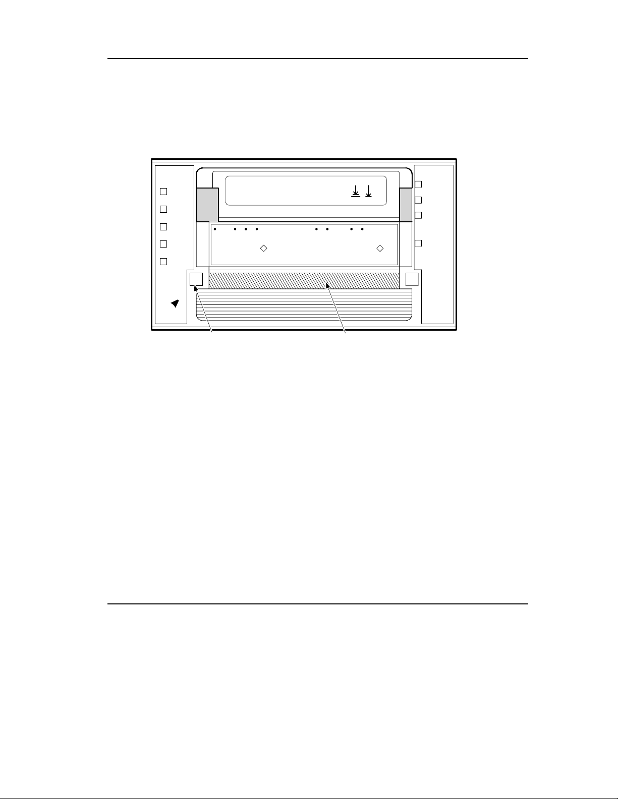
Figure 2-1 shows the DLT2000.
2.6
6.0
10.0
Compress
Density
Override
Density
Select
Handle
Open this
Remove Tape
Wait
To Unload
Press Button
Light
Installing and Configuring the DLT2000 Tabletop Drive
Write
Protected
Tape in Use
Use
Use
Cleaning
Handle
Close this
Handle
Open this
Insert Tape
Wait
To Load
Light
Tape
Operate
Handle
Unload
SELECT BUTTON
CARTRIDGE INSERT/RELEASE HANDLE (DOWN)
ZKO-1217-02-DG
Figure 2-1 Drive Front Panel
DLT2000/DLT2500/DLT2700 Cartridge Tape Subsystem 2-3
Page 30

Installing and Configuring the DLT2000 Tabletop Drive
2.3 Install the Subsystem
To install the DLT2000:
Step Action
1 Note the DLT2000 factory settings.
2 Review Section 2.4.1.
3 Configure the DLT2000 for use on your system:
If you need to ………… See section …………
Disable parity checking 2.4.2
Change the SCSI ID 2.4.3
4 Connect the cables.
2.4 Configure the DLT2000 Tabletop
This section describes how to configure the DLT2000 including:
Topic Section
Configuration Guidelines 2.4.1
Disable Parity Checking 2.4.2
Changing the SCSI ID 2.4.3
The DLT2000 is factory set to SCSI ID 5, unless otherwise specified. The drive is
factory set for parity generation and checking is enabled.
2.4.1 Configuration Guidelines
All system uses the SCSI ID to identify, or address, the DLT2000. Follow these
guidelines when configuring the DLT2000 for use on your system:
If you are installing the DLT2000 as ………… Then …………
The only SCSI device on the bus or one
of multiple SCSI devices on the bus
The last or only device on the SCSI bus
2-4 DLT2000/DLT2500/DLT2700 Cartridge Tape Subsystem
Be sure to use a SCSI ID that is
unique from any other device or
system ID on the SCSI bus.
You must terminate the bus by
installing a terminator on the drive.
Page 31

2.4.2 Disable Parity Checking
To disable parity, see your service representative.
2.4.3 Changing the SCSI ID
To change the SCSI ID use the pushbutton switch on the rear of the drive. Press the
switch button(s) above or below the number display (0-7) to set the desired SCSI ID.
Press the top button to increase the number or press the bottom button to decrease the
number.
Installing and Configuring the DLT2000 Tabletop Drive
Figure 2-2 Changing the SCSI ID via the Pushbutton Switch
2.5 Connect the Cables
Section 2.5 includes the following topics:
Topic Section
Examine the DLT2000 Rear Panel 2.5.1
Connect the SCSI Signal Cable 2.5.2
Terminate the SCSI Bus 2.5.3
Connect the Power Cord 2.5.4
0
0
MLO-012870
DLT2000/DLT2500/DLT2700 Cartridge Tape Subsystem 2-5
Page 32

Installing and Configuring the DLT2000 Tabletop Drive
2.5.1 Examine the DLT2000 Rear Panel
Examine the components on the DLT2000 rear panel to complete the physical
installation (Figure 2-3).
I
O
0
Power
Switch
Power
Connector
SCSI Signal
Connector (IN)
Figure 2-3 Rear Panel Components
2.5.2 Connect the SCSI Signal Cable
To connect the SCSI signal cable:
1. Connect one end of the SCSI cable to the leftmost SCSI signal connector on the
DLT2000 rear panel.
2. Snap the wire cable clamps into place to secure the cable.
3. Connect the other end of the SCSI signal cable to the SCSI connector on your
system or, for daisy-chained configurations, to another SCSI device.
See your system documentation for system SCSI connections.
SCSI Signal Connector
(Out/Termination)
MLO-012869
2-6 DLT2000/DLT2500/DLT2700 Cartridge Tape Subsystem
Page 33

2.5.3 Terminate the SCSI Bus
_________________________Note _____________________________
The SCSI bus must be terminated at both ends and at least
one device must supply terminator power.
___________________________________________________________
Table 2-1 indicates when and where to add a terminator.
Table 2-1 Adding a Terminator
If the DLT2000 is ………… Then …………
The last or only device on the bus
and you are going to terminate the
cables externally
Not the last or only device on the
SCSI bus
Installing and Configuring the DLT2000 Tabletop Drive
1. Connect the SCSI terminator to one
of the SCSI signal connectors on the
DLT2000 rear panel.
2. Snap the wire cable clamps into place
or tighten screws (whichever is
supplied) to secure the terminator.
Be sure to install the terminator at the end
of the bus.
The DLT2000 to supply TRM PWR on the bus by adding a jumper to the pins labeled
TRM PWR on the controller module.
2.5.4 Connect the Power Cord
To connect the power cord:
1. Ensure the DLT2000 power switch is set to 0.
2. Connect the power cord to the DLT2000 power connector. Make sure the
connector is fully seated.
3. Connect the other end of the power cord to a nearby ac outlet.
DLT2000/DLT2500/DLT2700 Cartridge Tape Subsystem 2-7
Page 34

Installing and Configuring the DLT2000 Tabletop Drive
2.6 Test the Installation
Section 2.6 includes the following topics:
Topic Section
Run the Power-On Self-Test (POST) 2.6.1
What to Do after POST 2.6.2
2.6.1 Run POST
To test the installation for the DLT2000 by running POST:
1. Turn on the system power.
2. Set the power switch on the DLT2000 rear panel to on. POST runs automatically.
3. Observe the indicators on the DLT2000 front panel. Ensure the indicator sequence
of events is the same as in Table 2-2 . Events on the right and left sides happen at
the same time.
Table 2-2 POST
Event Action
1
2
3
4
The lights on the right front panel turn on sequentially from
top to bottom. All lights stay on for a few seconds.
All lights on the left front panel turn on at the same time for
about three seconds and then turn off.
The green Operate Handle, the orange Write Protected, and
the Yellow Use Cleaning Tape lights turn off. The yellow
Tape in Use light blinks while the tape drive initializes.
After initialization, if no cartridge is loaded, the yellow Tape
In Use light turns off, the green Operate Handle light turns on,
the handle unlatches, and the beeper sounds.
For more information on what happens after initialization when a cartridge is present,
but the handle is down; or a cartridge is present, but the handle is up (not
recommended), see Section 3.5.4 in Chapter 3.
POST completes in about 13 seconds and the drive responds normally to all commands.
However, it might take longer for the media to become ready. After a bus reset, the tape
drive responds within a bus selection timeout period.
2-8 DLT2000/DLT2500/DLT2700 Cartridge Tape Subsystem
Page 35

2.6.2 What to Do after POST
If ………… Then …………
All the events in Table 2-2 took
place
All left- or right-side lights on the
DLT2000 front panel blink only
Installing and Configuring the DLT2000 Tabletop Drive
Table 2-3 After POST
POST succeeded. Bring up the system
and run the optional system tests. See
Chapter 3 for operating the drive and
selecting density.
POST failed. See Table 2-4.
DLT2000/DLT2500/DLT2700 Cartridge Tape Subsystem 2-9
Page 36

Installing and Configuring the DLT2000 Tabletop Drive
2.7 DLT2000 Troubleshooting Chart
If the DLT2000 fails during POST or operation, use Table 2-4 to determine the
problem and the action to take.
Table 2-4 DLT2000 Troubleshooting Chart
If. . .
Your system does
not recognize the
DLT2000
The SCSI ID might
The parameters for
The SCSI signal cable
The SCSI terminator
The SCSI bus might
Then . . . You should. . .
Your system might not
be configured to see
Configure your system to see the
ID.
the SCSI ID
Change the SCSI ID and
not be unique
reconfigure the system. New ID
effective at next power-on.
Check your SCSI adapter
your SCSI adapter
installation.
might be incorrect
Make sure the connector on each
might be loose
end of the cable is fully seated.
Install the terminator; make sure
might not be present or
the terminator is fully seated.
might be loose
If the DLT2000 is the last or only
not be correctly
terminated
device on the bus, make sure the
terminator is installed on the
DLT2000.
If the DLT2000 is not the last or
only device on the bus, check the
cable connections and make sure
the terminator is installed at the
The SCSI terminator
might not be at the
end of the bus, or
more than two
end of the bus.
Be sure to install a terminator at
each end of the bus. One
terminator is usually installed at
the system.
terminators might be
present
2-10 DLT2000/DLT2500/DLT2700 Cartridge Tape Subsystem
Page 37

Installing and Configuring the DLT2000 Tabletop Drive
Table 2-4 DLT2000 Troubleshooting Chart (cont’d)
If. . .
Your system does not
recognize the
DLT2000
Then . . . You should. . .
1. The SCSI bus
might be too long.
2. Too many devices
might be on the
bus.
1. Limit the bus length to the
ANSI SCSI standard of 6
meters (19 feet) for single
ended (SE) or 25 meters (82
feet) for differential
2. Limit the number of devices on
the bus (including the system)
to eight
Check your system configuratio n
The DLT2000 does
not power up
All right-side or all
left-side indicators on
The DLT2000 has no
power
A drive fault has
occurred
the DLT2000 front
panel blink
rules.
Check the DLT2000 power cord
connections with the DLT2000
power switch off
Press the Unload button on the
DLT2000 front panel to clear the
error. If unsuccessful power off,
then on, and look at indicators to
determine if POST executed
You are finding fatal
or nonfatal errors for
which you cannot
determine the cause
The bus termination
or SCSI signal cable
connections might be
incorrect
The ac power source
grounding might be
incorrect
successfully.
Make sure the SCSI bus is
terminated.
Use an ac outlet for the DLT2000
on the same ac line powering the
system.
After taking the action listed in Table 2-4, power on the DLT2000 to rerun POST. If all
right- or left-si de lights blink again, you most likely have a hardware failure.
DLT2000/DLT2500/DLT2700 Cartridge Tape Subsystem 2-11
Page 38

Installing and Configuring the DLT2000 Tabletop Drive
2-12 DLT2000/DLT2500/DLT2700 Cartridge Tape Subsystem
Page 39

Chapter 3
Configuring and Operating the DLT2000
Basic Tape Drive
3.1 In This Chapter
The configuration section in this chapter applies to the basic drive without the SCSI ID
switchpack and power supply. (Chapter 2 applies to configuring the tabletop). Chapter
3 includes these main topics and sections:
Topic Section
Before You Install the DLT2000 Drive 3.2
Overview of the Front Panel 3.4
Selecting Density 3.3
Description of Controls and Indicators 3.5
Description of the Tape Cartridge 3.6
Loading a Cartridge 3.7
Using the Cleaning Tape Cartridge 3.8
Unloading a Cartridge 3.9
Preserving Cartridges 3.10
3.2 Before You Install the DLT2000 Drive
Section 3.2 includes:
Topic Section
Disabling Parity Checking 3.2.1
Changing the SCSI ID 3.2.2
Setting the TRM ENB/TRM PWR jumpers 3.2.3
Locating the SCSI Cable and Power Connectors 3.2.4
DLT2000/DLT2500/DLT2700 Cartridge Tape Subsystem 3-1
Page 40

Configuring and Operating the DLT2000 Basic Tape Drive
3.2.1 Disabling Parity Checking
If your system does not generate parity, you can disable parity checking by adding a
jumper to the SCSI connector on the left side of the DLT2000 drive (Figure 3-1).
To disable parity:
1. Use Figure 3-1, Number
Front
Bezel
Left Side
Right Side
, to locate the SCSI ID connector on the drive.
1. TRM PWR/TRM ENB Connector
2. SCSI ID Connector
3. Loader Connector
1
Front
Bezel
32
ZKO−1217−17−RGS
Figure 3-1 DLT2000 Drive Connectors
3-2 DLT2000/DLT2500/DLT2700 Cartridge Tape Subsystem
Page 41

Configuring and Operating the DLT2000 Basic Tape Drive
Figure 3-2 shows what the pins on the SCSI ID connector represent.
Disable
Remote ID
Present
Parity
ID Pins
LKG-9295-9 4F
Figure 3-2 SCSI ID Connector Pins
_________________________Note _____________________________
A jumper must always be placed on the Remote ID Present
position (Figure 3-2) for the host to recognize any ID
selection on this connector.
___________________________________________________________
DLT2000/DLT2500/DLT2700 Cartridge Tape Subsystem 3-3
Page 42
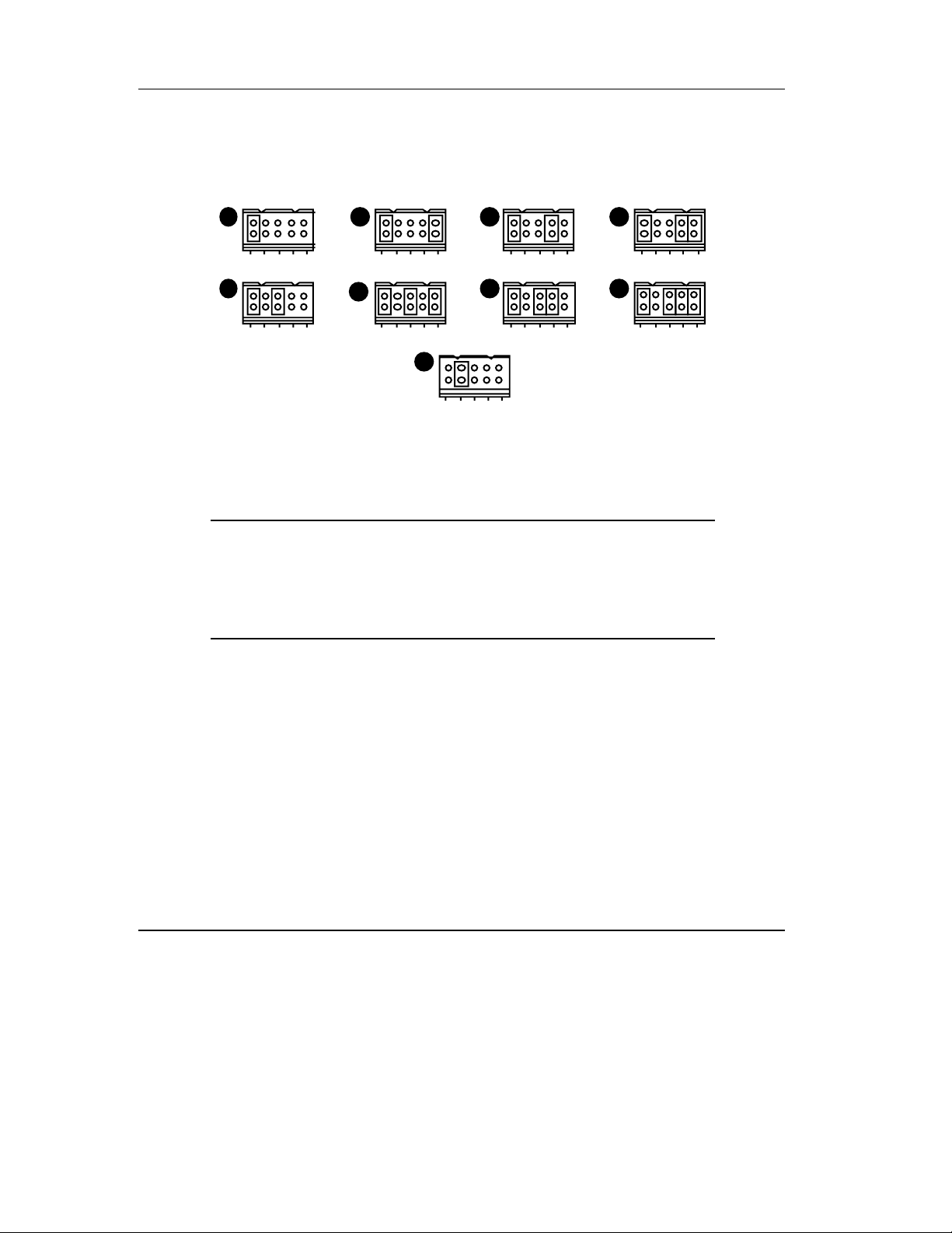
Configuring and Operating the DLT2000 Basic Tape Drive
2. Place the jumper in the disable parity check position, as shown in Letter I, Figure
3-3.
8 - Bi t
A B C D
E
F
Figure 3-3 Jumper Positions
A. SCSI ID 0 D. SCSI ID 3 G. SCSI ID 6
B. SCSI ID 1 E. SCSI ID 4 H. SCSI ID 7
C. SCSI ID 2 F. SCSI ID 5 I. Disable parity checking.
3.2.2 Changing the SCSI ID
The drive is shipped with SCSI ID 5, unless otherwise specified. You can change the
SCSI ID by adding jumpers to the drive's SCSI connector (Figure 3-1).
HG
I
LKG-9294-94f
The jumper goes in this
position with any SCSI ID
you choose.
To change the SCSI ID:
1. Use Figure 3-1, number
, to locate the SCSI ID connector on the drive.
2. Choose a SCSI ID from 0 to 7.
3. Use Figure 3-3, to see where to place the jumpers for the ID you choose. For
example, if you chose SCSI ID 1, place the jumpers in the same positions as those
in Letter B.
3-4 DLT2000/DLT2500/DLT2700 Cartridge Tape Subsystem
Page 43

Configuring and Operating the DLT2000 Basic Tape Drive
3.2.3 Setting the TRM ENB (Single-ended Only)/TRM PWR
Jumpers
_________________________Note _____________________________
The Small Computer System Interface (SCSI) bus must be
terminated at both ends of the bus, and at least one device
must supply terminator power.
___________________________________________________________
The single-ended DLT2000 controller module has active terminators. The differential
DLT2000 controller module does not have on-board termination. You can configure the
single-ended DLT2000 drive to supply termination power and termination on the bus.
To supply terminator power and provide termination for the SCSI bus:
1. Use Figure 3-1, number
drive.
2. Place jumpers in the positions shown in Figure 3-4, number
Figure 3-4 Jumper Settings for TRM PWR/TRM ENB Connector
No Term
Power/Disable
Active Termination
No Term
Power/Enable
Active Termination
, to locate the TRM PWR/TRM ENB connector on the
1
2 4
Term Power/Disable Active
Termination
Term Power/Enable Active
Termination
3
ZKO−1217−18−RGS
.
DLT2000/DLT2500/DLT2700 Cartridge Tape Subsystem 3-5
Page 44

Configuring and Operating the DLT2000 Basic Tape Drive
3.2.4 Locating the SCSI Cable and Power Connectors
To install the DLT2000 drive, note the location of the rear connectors (Figure 3-5).
Rear A
1
Rear B
Figure 3-5 DLT2000 Rear Connectors
SCSI Connector
2
3
Power Connector
Power Connector (Storage Works Option)
ZKO−1217−16−RGS
3-6 DLT2000/DLT2500/DLT2700 Cartridge Tape Subsystem
Page 45

3.3 Selecting Density
Section 3.3 describes the drive's density select features.
_________________________Caution __________________________
If a prerecorded tape and write from beginning of tape (BOT), all
prerecorded data is lost. This includes density changes, since they only
occur when writing from BOT.
___________________________________________________________
Ways of Selecting Density
Using CompacTape III the density defaults to 10.0 GB native. The only selection is for
this cartridge is 2.6, 6.0 10.0 comp ression off or 20.0 GB compression on.
Using the CompacTape III the user can select density by using any of the following
operations:
1. On all read operations and all write append operations, the recorded density is the
density to be used.
2. On a Write from BOT, the tape density may be changed by:
• The Density Select button. Using the Density Select button always
overrides a host sele ction.
Configuring and Operating the DLT2000 Basic Tape Drive
• A programmable host sel ection via your operating system. (The Density
Override light is off, indicating automatic or host density selection.)
•••• Native default density 10.0 and Compress (assuming the Density Select
button or the host selection was not used.)
How to Select Density
To select density with the DLT2000:
1. Load the tape in the drive. The yellow Tape in Use light blinks while the tape loads
and calibrates.
2. After calibration completes, Tape in Use remains lit.
3. The light shows the tape's prerecorded density, such as 2.6 or 6.0.
DLT2000/DLT2500/DLT2700 Cartridge Tape Subsystem 3-7
Page 46

Configuring and Operating the DLT2000 Basic Tape Drive
4. You can use the drive's control panel at various times, not just after loading a tape.
Density selection is inactive until the write from BOT command is issued. The
controller remembers the density selection state until you do one of the following:
• Change the density selection
• Unload the tape
Density Select Example
If you have loaded a tape with a prerecorded 2.6 density and you use the Density Select
button to select 10.0 density, the following should happen:
• The 2.6 light remains lit—density has not changed yet and the steady light indicates
recorded tape density
• The 10.0 light blinks—densi t y cha nge is pending
• Density Override lights
When a write from BOT occurs, the following should happen:
• The 2.6 light turns off
• 10.0 lights steadily
• Density Override remains lit
3-8 DLT2000/DLT2500/DLT2700 Cartridge Tape Subsystem
Page 47

Configuring and Operating the DLT2000 Basic Tape Drive
Table 3-1 shows the results of density selection.
Table 3-1 Results of Density Selection
If ………… Then …………
The Density Select button is not
used
The lights show the actual density when the tape is
reading and writing. The lights are on steady and
Density Override is off.
The Density Select button is
used, and if the actual tape
density is the same as the density
you selected
The actual density and the Density Override light.
For example, if the actual tape density is 10.0 GB
and the selected tape density is 10.0 GB, then the
indicator next to 10.0 lights.
The Density Select button is
used, and if the actual tape
density differs from the density
selected
1. The light with the actual density is on steady
2. The light with the selected density blinks
3. Density Override lights steady
For example, if the actual tape density is 10.0 and
the selected density is 6.0, 10.0 lights steady, 6.0
blinks, and Density Override lights stead y.
To select density over the SCSI bus:
1. Do a SCSI MODE SELECT with the density you want. For more details, see
Chapter 8.
2. Write data to the tape from BOT.
DLT2000/DLT2500/DLT2700 Cartridge Tape Subsystem 3-9
Page 48
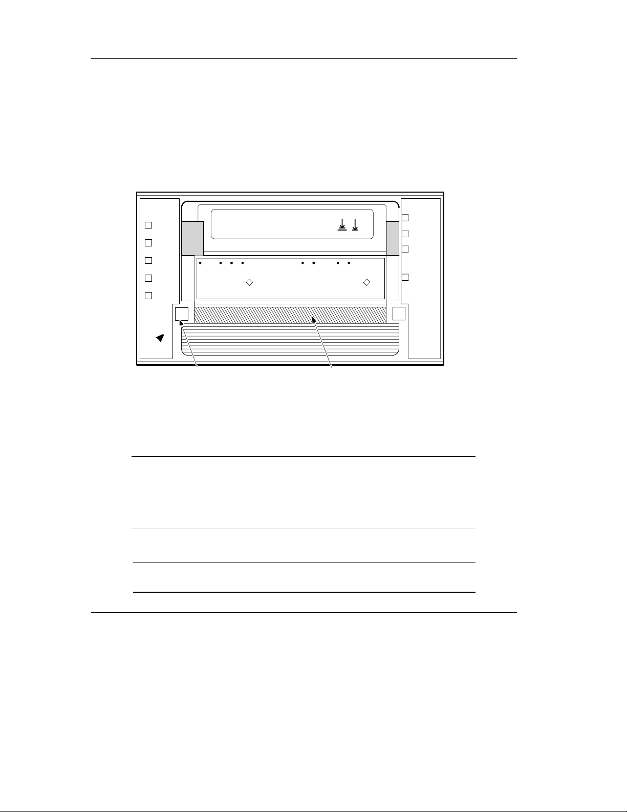
Configuring and Operating the DLT2000 Basic Tape Drive
3.4 Overview of the Front Panel
The DLT2000 has the following indicators and controls for operating the drive Figure
3-6):
2.6
6.0
10.0
Compress
Density
Override
Density
Select
Handle
Open this
Remove Tape
Wait
To Unload
Press Button
Light
Handle
Close this
Insert Tape
Handle
Open this
Wait
To Load
Light
Write
Protected
Tape in Use
Use
Use
Cleaning
Tape
Operate
Handle
Unload
SELECT BUTTON
CARTRIDGE INSERT/RELEASE HANDLE (DOWN)
Figure 3-6 DLT2000 Indicators
Indicators (Left Side of Drive) Indicators (Right Side of Drive)
Density light 2.6 Write Protected light
Density light 6.0 Tape in Use light
Density light 10.0 Use Cleani ng Tape light
Compress light Operate Handle light
Density Override light Beeper (audible) not visible
Controls
Density Select button Unload button
Cartridge insert/release handle
3-10 DLT2000/DLT2500/DLT2700 Cartridge Tape Subsystem
ZKO-1217-02-DG
Page 49

Configuring and Operating the DLT2000 Basic Tape Drive
3.5 Description of Controls and Indicators
Section 3.5 includes the following sections:
Topic Section
Beeper 3.5.1
Unload Button 3.5.2
Cartridge Insert/Release Handle 3.5.3
Indicator Action during Power-on Self-test and
Operation
3.5.1 Beeper
A beeper sounds when you can operate the cartridge insert/release handle. When you
hear the beep, the green Operate Handle light should be on. To prevent damage to the
drive wait for the sound of the beeper before opening the door!!
3.5.2 Unload Button
The Unload button is used primarily to unload the tape. When the user pushes Unload,
the DLT2000 waits until an active write to tape is completed before beginning the
unload sequence.
3.5.4
The drive then rewinds the tape back into the cartridge. The tape must be completely
rewound and unloaded into the cartridge before you can remove the cartridge from the
drive. An unload operation may take 20 seconds from BOT.
If the drive is in error state (all right-side lights are flashing on the front panel), pushing
the Unload button causes the drive to reset and unload the tape if possible.
3.5.3 Cartridge Insert/Release Handle
Operate the cartridge insert/release handle to load a cartridge or to eject a cartridge only
when the Operate Handle light is on, and after the momentary beep sounds. The handle
lifts to the open position and lowers to the closed position. See Section 3.7 and Section
3.9 for the operating procedures.
DLT2000/DLT2500/DLT2700 Cartridge Tape Subsystem 3-11
Page 50

Configuring and Operating the DLT2000 Basic Tape Drive
3.5.4 Indicator Action during Power-On Self-Test and Operation
When you turn on system power, the drive performs the power-on self-test (POST). The
sequence of events is:
3-12 DLT2000/DLT2500/DLT2700 Cartridge Tape Subsystem
Page 51

Configuring and Operating the DLT2000 Basic Tape Drive
Table 3-2 POST Sequence of Events
Stage What Happens
1. The lights on the right front panel turn on sequentially from top to bottom. All
lights stay on for a few seconds.
2. The lights on the left front panel turn on at the same time for about three
seconds and then turn off.
3. The green Operate Handle, the orange Write Protected, and the yellow Use
Cleaning Tape lights turn off. The yellow Tape in Use light blinks while the
4. After initialization, the drive is in one of the following four states:
tape drive initializes.
Drive State Indicator Displays and Actions
a. No cartridge is present
1. The yellow Tape in Use light turns off.
2. The green Operate Handle light turns on.
3. The handle is unlatched.
4. The drive beeps momentarily.
You can now raise the handle and insert a
b. A cartridge is present
and the handle is down
cartridge.
The drive loads the cartridge. When the yellow
Tape In Use light stops blinking and stays on,
the tape's actual density lights. For example, if
the actual tape density is 2.6 GB, then the light
turns on next to the 2.6 label. When Density
Override blinks, you can select a density. The
c. A cartridge is present,
but the handle is up (not
recommended)
d. A cartridge is not
present and the handle
could be up (not
recommended)
drive is ready for use. (See Section 3.4.)
The yellow Tape In Use light turns off. The
green Operate Handle light flashes. When you
lower the handle, the cartridge loads.
The yellow Tape In Use light turns off. The
green Operate Handle light flashes. When you
lower the handle, the cartridge loads.
DLT2000/DLT2500/DLT2700 Cartridge Tape Subsystem 3-13
Page 52

Configuring and Operating the DLT2000 Basic Tape Drive
Table 3-2 POST Sequence of Events Cont’d
Stage What Happens
Drive State Indicator Displays and Actions
e. The drive detects an
error condition
Then all right or left side lights blink repeatedly.
You may try to unload the tape and reinitialize
the drive by pressing the Unload button or turn
drive power off and then on again. The right- or
left-side lights stop blinking and the drive tries
to reinitialize. The lights turn on steady again
and turn off if the test succeeds.
POST completes in about 15 seconds and the drive responds normally to all commands.
However, it might take longer for the media to become ready. After a bus reset, the tape
drive responds within a bus selection timeout period. Use this table to determine the
drive's operating condition:
Table 3-3 Determining the Drive's Operating Condition
Label Color State Operating Condition
Light (Right front panel)
Write Protected Orange On
Off
Tape in Use Yellow Blinking
On
Use Cleaning Tape Yellow On Drive head needs cleaning, or the
Remains on after
you unload the
cleaning tape
After cleaning,
turns on again
when you reload
he data cartridge
Off Cleaning is complete, or cleaning
Tape is write-protected.
Tape is write-enabled.
Tape is moving.
Tape is loaded; ready for use.
tape is bad (Section 3.8).
Cleaning tape attempted to clean
the drive head, but the tape
expired, so cleaning was not
done.
Problem data cartridge. Try
another cartridge.
is unnecessary.
3-14 DLT2000/DLT2500/DLT2700 Cartridge Tape Subsystem
Page 53

Configuring and Operating the DLT2000 Basic Tape Drive
Table 3-4 Determining the Drive's Operating Condition (cont’d)
Label Color State Operating Condition
Light (Left Front Panel)
Operate Handle Green On Okay to operate the
cartridge/insert release handle.
Off Do not operate the cartridge
All four right-sid e
– On POST is starting.
insert/release handle.
lights or all left-side
lights
Blinking An error has occurred. See Table
2-4, DLT2000 Troubleshooting
Chart.
2.6 Yellow On
Blinking
Tape is recorded in 2.6 format.
Tape is recorded in another
density. You selected this
6.0 Yellow On
Blinking
density for a write from BOT.
Tape is recorded in 6.0 format.
Tape is recorded in another
density. You selected this
10.0 Yellow On (default)
Blinking
density for a write ROM BOT.
Tape is recorded in 10.0 format.
Tape is recorded in another
density. You selected this
density for a write from BOT.
Compress Yellow On Compression mode is enabled.
(Compression can be done in
10.0 density only.)
Off Compression mode is disabled.
Density Override Yello w On You selected a density from the
front panel.
Off (default) Density to be selected by the
host (automatic) .
Blinking You are in density selection
mode.
DLT2000/DLT2500/DLT2700 Cartridge Tape Subsystem 3-15
Page 54

Configuring and Operating the DLT2000 Basic Tape Drive
Table 3-4 Determining the Drive's Operating Condition (cont’d)
Label Color State Operating Condition
Light (Left Front Panel)
All four right-sid e or
Blinking A POST error occurred.
all left-side lights
3-16 DLT2000/DLT2500/DLT2700 Cartridge Tape Subsystem
Page 55

Configuring and Operating the DLT2000 Basic Tape Drive
3.6 Description of the Tape Cartridge
The CompacTape III tape cartridge is a 4-inch, gray/brown, plastic cartridge containing
1100 feet of 1/2 inch magnetic metal particle tape.
3.6.1 Cartridge Write-Protect Switch
The tape cartridge has a write-protect switch to prevent accidental erasure of data.
Before loading the tape cartridge into the drive, position the write-protect switch on the
front of the cartridge (Figure 3-7).
• Left, so the cartridge is write-protected
• Right, so the cartridge is write-enabled
When you slide the switch to the left, the small orange rectangle is visible. This means
data cannot be written to the tape. The arrow (beneath the orange rectangle and over the
two lines on the write-protect switch) lets you know that data cannot be written to the
tape.
When the switch is moved to the right (the orange rectangle is not visible) the tape can
be written.
DLT2000/DLT2500/DLT2700 Cartridge Tape Subsystem 3-17
Page 56

Configuring and Operating the DLT2000 Basic Tape Drive
Figure 3-7 shows the write-protect switch on the tape cartridge :
ORANGE
INDICATOR
WRITE-
PROTECT
SWITCH
WRITEENABLED
WRITEPROTECTED
Figure 3-7 Tape Cartridge
3-18 DLT2000/DLT2500/DLT2700 Cartridge Tape Subsystem
ZKO-1217-04-DG
Page 57

3.6.2 Data Protection
When the cartridge write-protect switch is to the left, the drive turns on the write protect
LED immediately. But, if the drive is writing to the tape, write protect does not take
effect until the write completes.
Table 3-5 describes what happens to data protection when you move the write-protect
switch before loading the cartridge.
If you move the write-protect switch ………… Then …………
To the left, the tape is write-protected; the
orange indicator on the cartridge shows
To the right, the tape is write-enabled Data can be written to the tape
Table 3-6 describes what happens to data protection when you move the write-protect
switch during operation.
Configuring and Operating the DLT2000 Basic Tape Drive
Table 3-5 Before Loading the Cartridge
Data cannot be written to the
tape.
(if it is not software writeprotected).
Table 3-6 After Loading the Cartridge and Operating
If you move the write-protect switch ………… Then …………
From the write-protected position to writeenabled
The tape becomes writeenabled after a variable amount
of time (seconds).
From write-enabled to write-protected The tape becomes write-
protected after a variable
amount of time (seconds).
DLT2000/DLT2500/DLT2700 Cartridge Tape Subsystem 3-19
Page 58

Configuring and Operating the DLT2000 Basic Tape Drive
3.7 Loading a Cartridge
The following are more detailed steps for loading a cartridge (Figure 3-8):
1. When the green light is on steady, pull the cartridge
insert/release handle open.
2. Insert the cartridge.
3. Push the cartridge into the drive.
4. Push the handle closed.
The green light turns off and the yellow light blinks to show the tape is loading. When
the tape is at the BOT marker, the yellow light turns on steady. The tape is now ready
for use.
3-20 DLT2000/DLT2500/DLT2700 Cartridge Tape Subsystem
Page 59

Configuring and Operating the DLT2000 Basic Tape Drive
Figure 3-8 shows how to load a cartridge into the drive.
Handle
Unload
2.
1.
4.
3.
Unload
ZKO-1217-10-DG
Figure 3-8 Loading a Cartridge
DLT2000/DLT2500/DLT2700 Cartridge Tape Subsystem 3-21
Page 60

Configuring and Operating the DLT2000 Basic Tape Drive
3.7.1 Tape in Use
Whenever the yellow Tape in Use light is on steady, the tape is ready to use. When the
tape is being read, written, or rewound, Tape in Use light blinks.
Use Table 3-7 to dete rmine what is happening during cartridge use.
Table 3-7 What is Happening During Cartridge Use (Right Side Lights)
If ………… It means …………
The yellow light is on steady A cartridge is loaded, but the tape is not moving.
This can mean no application is communicating
with the controller, or that the application is
communicating, but is no t delivering commands
The yellow light blinks
irregularly
The yellow light blinks
regularly
The green light turns on and
the beeper sounds
All four lights blink An error has oc curred during operation. See
for tape motion.
A calibration read or write is in progress.
The tape i s l oading, unloading, or rewinding.
The tape is unloaded into the cartridge and the
cartridge can now be removed, or if the drive is
unloaded, a cartridge can now be inserted.
Table 2-4, DLT2000 Troubleshooting Chart.
3-22 DLT2000/DLT2500/DLT2700 Cartridge Tape Subsystem
Page 61

Configuring and Operating the DLT2000 Basic Tape Drive
3.8 Using the Cleaning Tape Cartri dge
Use Table 3-8 to determine when to use the cleaning cartridge.
Table 3-8 When to Use the Cleaning Cartridge
If ………… It means ………… And you should …………
1. Use Cleaning Tape
lights (Figure 3-6 )
2. A data cartridge
causes Use Cleaning
Tape to blink
3. Use Cleaning Tape
still lights after you
clean the drive head
4. Use Cleaning Tape
lights after you load
the cleaning cartridge
The drive head needs
cleaning or the tape is
bad (see item 3)
The data cartridge
may be damaged
Your data cartridge
may be causing the
problem
Cleaning has not been
done and the
cartridge is expired
Use the cleaning cartridge.
Follow the instructions in
Section 3.7 for loading a
cartridge into the drive.
When cleaning completes,
the beeper sounds for you to
remove the cleaning
cartridge.
Back up this data onto
another cartridge. Discard
the old cartridge, which may
be damaged. A damaged
cartridge may cause
unnecessary use of the
cleaning cartridge.
Try another data cartridge.
Replace the cleaning
cartridge.
_________________________Note _____________________________
The cleaning cartridge expires after about 20 uses.
___________________________________________________________
DLT2000/DLT2500/DLT2700 Cartridge Tape Subsystem 3-23
Page 62

Configuring and Operating the DLT2000 Basic Tape Drive
3.9 Unloading a Cartridge
_______________________CAUTIONS ___________________________
Remove a cartridge from the drive before turning off host system power. Failure to
remove a cartridge can result in cartridge and drive damage.
When you remove the cartridge from the drive, return the cartridge to its plastic case to
prolong the cartridge life.
____________________________________________________________
To unload a cartridge from the drive (Figure 3-9):
1. Press the Unload button (or issue the appropriate system software command). The
yellow Tape in Use light blinks as the tape rewinds.
2. When the green light turns on (the beeper also sounds), pull the cartridge
insert/release handle open to eject the cartridge.
__________________________CAUTION _________________________
Immediate extraction of the tape cartridge can lead to tape leader failure.
Delay tape cartridge extraction by one to two seconds to avoid this
problem.
____________________________________________________________
3. Remove the cartridge.
4. Push the handle closed.
3-24 DLT2000/DLT2500/DLT2700 Cartridge Tape Subsystem
Page 63

Configuring and Operating the DLT2000 Basic Tape Drive
Unload
2.
1.
4.
3.
ZKO-1217-09-DG
Figure 3-9 Unloading a Cartridge
DLT2000/DLT2500/DLT2700 Cartridge Tape Subsystem 3-25
Page 64

Configuring and Operating the DLT2000 Basic Tape Drive
3.10 Preserving Cartridges
For longer life of recorded or unrecorded cartridges, store cartridges in a clean
environment with these conditions:
• Do not drop or bang the cartridge. This can displace the tape leader, making the
cartridge unusa ble and possibly damaging the drive.
• Keep tape cartridges out of direct sunlight and away from heaters and other heat
sources.
• Store tape cartridges in temp eratures between 10°C and 40°C (50°F to 104°F). For
longer cartridge life, always store the cartridge in its plastic container and in room
environment conditions of 72°F ±7°F (22°C ±4°C).
• If the tape cartridge has been exposed to heat or cold extremes, stabilize the
cartridge at room temperature for the same amount of time it was exposed---up to
24 hours.
• Do not place cartridges near electromagnetic interference sources, such as
terminals, motors, and video or X-ray equipment. Data on the tape can be altered.
• Store tape cartridges in a dust-free environment where the relative humidity is
between 20% and 80%. For longer cartridge life, store the cartridge at 40% ± 20%
relative humidity.
• Place an identification label only in the slide-in slot on the front of the cartridge.
• Do not adhere labels to a cartridge anywhere except in the slide-in slot.
3-26 DLT2000/DLT2500/DLT2700 Cartridge Tape Subsystem
Page 65

Chapter 4
Configuring and Operating the DLT2500
Mini-Library
4.1 In This Chapter
The configuration section in this chapter applies to the mini-library and its operation.
Chapter 4 includes these main topics and sections:
Topic Section
Introduction to the Mini-Library 4.2
Configure the DLT2500 Mini-Library 4.3
Installation Test 4.4
Operator Control Panel 4.5
Key Lock 4.6
Selecting Density 4.7
Default Operating Modes 4.8
Tape Cartridge Description 4.9
Magazine Description 4.10
When to Use the Cleaning Tape Cartridge 4.11
DLT2000/DLT2500/DLT2700 Cartridge Tape Subsytem 4-1
Page 66

Configuring and Operating the DLT2500 Mini-Library
Shipping Screw
Figure 4-1 Loosening the Shipping Screw Under the Mini-Library
4-2 DLT2000/DLT2500/DLT2700 Cartridge Tape Subsytem
Locking Lever
MLO–012160
Page 67

Configuring and Operating the DLT2500 Mini-Library
MLO–012863
Figure 4-2 Rotate the Locking Lever
Lift the locking lever on the front of the mini-library (Figure 4-2) to rotate the magazine
locking mechanism. This allows you to remove the magazine from the mini-library.
DLT2000/DLT2500/DLT2700 Cartridge Tape Subsytem 4-3
Page 68

Configuring and Operating the DLT2500 Mini-Library
Label
Fan
Power Switch/Power Connector
SCSI Connectors
Figure 4-3 Mini-Library Rear Panel Components
4-4 DLT2000/DLT2500/DLT2700 Cartridge Tape Subsytem
MLO-012002
Page 69

Configuring and Operating the DLT2500 Mini-Library
Magazine Door
Display
Operator Buttons
Figure 4-4 Front of the DLT2500
DLT2000/DLT2500/DLT2700 Cartridge Tape Subsytem 4-5
MLO–012131
Key Lock
Page 70

Configuring and Operating the DLT2500 Mini-Library
4.2 Introduction to the Mini -Li br ary
The mini-library includes a DLT2000 tape drive, a media loader, and a 5-cartridge
removable magazine.
The same SCSI target controller board controls the tape drive and the media loader. If
the controller detects the loader's presence when the system is turned on, the loader is
presented as a SCSI-2 medium changer device on LUN 1.
If you issue the SCSI-2 medium changer commands to the DLT2500:
• Random access is enabled to the media stored in the magazine slots
• Sequential access is disabled to the media supported automatically in auto-loading
mode
If you do not issue the SCSI-2 medium changer commands, the default mode of
operation is sequential access to the media supported automatically in auto-loading
mode.
Auto-loading is implemented as a side effect of the SCSI UNLOAD command, as
shown:
If …………
An unload is
specified
After winding the tape back into the cartridge and
moving the cartridge from the drive to the magazine slot
Then …………
from which it came, the cartridge in the next slot is
The next slot is
moved from the magazine into the drive and made ready.
No cartridge is loaded into the drive.
empty, or the
cartridge unloaded
was for the last slot
in the magazine
4-6 DLT2000/DLT2500/DLT2700 Cartridge Tape Subsytem
Page 71

Configuring and Operating the DLT2500 Mini-Library
4.3 Configure and Install the DLT2500 Mini-Library
This section describes how to configure and install the mini-library including:
•= Configuration guidelines
•= Connecting the SCSI signal cable to the mini-library
The mini-library is factory set to SCSI ID 5, unless otherwise specified.
4.3.1 Configuration Guidelines
Your system uses the SCSI ID to identify, or address, the mini-library. Follow these
guidelines when you configure the mini-librar y for your system:
If you are installing the mini-library as …………
The only SCSI device on the bus or one of
multiple SCSI devices on the bus
Be sure to use a SCSI ID that is unique
from any other device or system ID on
Then …………
the SCSI bus.
If you need to change the SCSI ID, see
the section on setting the SCSI ID, later
in this chapter.
The last or only device on the SCSI bus The user must terminate the bus by
installing a terminator.
4.3.2 Connecting the SCSI Signal Cable to the Mini-Library
Examine the components on the mini-library rear panel (Figure 4-3) to complete the
physical installation.
To connect the SCSI signal cable:
1. Ensure the mini-library power is turned off.
2. Connect one end of the SCSI cable to an available SCSI signal connector on the
mini-library rear panel.
3. Snap the wire cable clamps into place or tighten the screws (whichever is supplied)
to secure the cable.
4. Connect the other end of the SCSI signal cable to the SCSI connector on your
system, or for daisy-chained configurations, to another SCSI device.
See your system documentation for system SCSI connections.
DLT2000/DLT2500/DLT2700 Cartridge Tape Subsytem 4-7
Page 72

Configuring and Operating the DLT2500 Mini-Library
4.4 Test the Installation
This section tells you how to run the power-on self-test (POST) and what to do after
POST.
4.4.1 Run POST
To test the inst allation for the mini-library by running POST:
1. Turn on the system power.
2. Set the power switch on the mini-library rear panel to on.
Result: POST runs automatically when you turn on the mini-library
3. Watch the display on the mini-library front panel. Ensure the sequence of events are
the same as listed:
Event
1 The message LDR RST (loader reset) displays.
2 The message LDR ACT (loader active) displays.
3 A series of numbers display as the mini-library elevator goes up
and down.
4 The message LDR RDY (loader ready) displays.
4.4.2 What to Do after POST
Verify whether the POST events took place.
If …………
All the events took place POST succeeded. The mini-library is ready for
All the events did not take
place
Action
Then …………
operation.
POST failed. You should see the message LDR RST
(loader reset) display.
1.Verify you terminated the SCSI bus.
2.Turn the mini-library power off and then on
again. If POST still does not succeed, call your
service representative.
4-8 DLT2000/DLT2500/DLT2700 Cartridge Tape Subsytem
Page 73

Configuring and Operating the DLT2500 Mini-Library
4.5 Operator Control Panel
The operator control panel (OCP) has 4 pushbuttons (Figure 4-5 and Table 4-1).
MLO-012191
Display
Mode
Figure 4-5 Mini-Library Operator Control Panel
Select
Load/
Unload
Open
DLT2000/DLT2500/DLT2700 Cartridge Tape Subsytem 4-9
Page 74

Configuring and Operating the DLT2500 Mini-Library
Table 4-1 lists each button and its function.
Table 4-1 Mini-Library Operator Control Panel
Button
Function
Display Mode Puts the mini-library in Normal, Density Select, or SCSI ID
Select
Load/Unload
Select mode.
•= Selects SCSI ID and density.
•= Moves in increments the current slot number on the
display to the next slot number .
• Loads the currently selected cartridge into the tape drive
• Unloads the cartridge currently in the tape drive
• Resets the mini-library if a loader error has occurred.
When the ERR LDR message displays, press the
Load/Unload button to reset the mini-library.
Open
•= Opens the magazine door to access the magazine for
loading and unloading cartr i dges.
•= Unloads the cartridge currently in the tape drive and
returns the cartridge to its original slot. Then, opens the
magazine door.
4-10 DLT2000/DLT2500/DLT2700 Cartridge Tape Subsytem
Page 75

Configuring and Operating the DLT2500 Mini-Library
Table 4-2 lists the display messages you can see during operation.
Table 4-2 Display Messages
Display Message
Tells you …………
WP The cartridge in the drive is write-protected by one of
these methods:
• The write-protect switch on the cartridge is set to the
write-protect position
DRV ACT
DRV RDY A cartridge is in the drive and the tape is not moving.
DRV REW Tape is rewinding.
HC Use cleaning tape.
LDR RDY Power is on and no cartridge is in the drive.
LDR ACT Loader is moving a cartridge.
• Host software write-protect qualifiers
Tape is reading or writing
ERR MAG The status of cartridges reported by the loader and the
ERR LDR A loader transfer assembly error occurred.
ERR DRV A drive error occurred.
ERR CTL A controller error occurred.
ERR UNK An error of unknown origin occurre d.
SLOT 0
SLOT 1
SLOT 2
SLOT 3
SLOT 4
drive is inconsistent.
The current slot containing the cartridge. Each current
slot number flashes in the display when its corresponding
cartridge moves to or from the drive. Also used with the
ERR MAG or ERR LDR message to show the type of
error.
DNS SEL The mini-library is in Density Select mode.
DLT2000/DLT2500/DLT2700 Cartridge Tape Subsytem 4-11
Page 76

Configuring and Operating the DLT2500 Mini-Library
Table 4-2 Display Messages (Cont’d)
Display Message
Tells you …………
OVR Tape drive activity as follows:
• On steady means you selected a density from the front
panel.
• Off (default) means density is selected automatically.
• Flashing means you are in density select mode.
2.6 Tape dr ive activity as follows:
• On steady means the tape is recorded in 2.6 format.
• Flashing means the tape is recorded in another
density. You selected this density for a write from
BOT.
6 Tape drive activity as follows:
• On steady means the tape is recorded in 6 GB format.
• Blinking means the tape is recorded in another
density. You selected this density for a write from
BOT.
10 Tape drive activity as follows:
• On steady means the tape is recorded in
10 GB format.
• Flashing means the tape is recorded in another
density. You selected this density for a write from
BOT.
10C Tape drive activity as follows:
• On means Compression mode is enabled.
Compression can be done in 10 GB density only.
• Off means Comp ression mode is disabled.
4-12 DLT2000/DLT2500/DLT2700 Cartridge Tape Subsytem
Page 77

4.6 Key Lock
The key lock on the front of the mini-library (Figure 4-3) enables or disables use of the
operator control p anel (OCP) (F igure 2-5). The key lock prevents unauthorized removal
of the magazine or cartridges, providing a measure of data security.
To unlock or enable the OCP, turn the key toward the opened lock icon next to the key
lock.
To lock or disable the OCP, turn the key toward the locked icon next to the key lock.
_________________________CAUTION _________________________
Do not force open the magazine door manually. Always use the Open
button to open the door electronically.
___________________________________________________________
4.6.1 OCP Locked or Disabled
When you insert the magazine into the mini-library and close the magazine door, the
elevator scans the magazine. The OCP pushbuttons are disabled.
Configuring and Operating the DLT2500 Mini-Library
4.6.2 OCP Unlocked or Enabled
The OCP pushbuttons unlocked or enabled allow operator intervention.
4.6.3 Setting the SCSI ID
Choose an unused SCSI ID between 0 and 7.
To set the SCSI ID via the front panel:
1. Press and hold the Display Mode button (about 5 seconds) until the SCSI ID SEL
message displays including the factory set SCSI ID.
SCSI ID SEL
SCSI ID 0
2. Keep pressing the Select button quickly until the ID number you want displays
(Figure 4-5).
3. Pre ss the Display Mode button again. See the display message LDR RDY. At this
point, the mini-library drive cannot yet recognize the SCSI ID.
DLT2000/DLT2500/DLT2700 Cartridge Tape Subsytem 4-13
Example
Page 78

Configuring and Operating the DLT2500 Mini-Library
4. Issue a bus reset or turn the mini-library power off and then on again so the drive
can recognize the new SCSI ID.
4.7 Selecting Density
This section describes the mini-library's density select feature.
__________________________Caution___________________________
If a prerecorded tape and write from beginning of tape (BOT), all
prerecorded data is lost. This includes density changes, since they only
occur when writing from BOT.
____________________________________________________________
The user can select density by using any of the following:
1. On a write from beginning of tape (BOT), tape density is selected by one of the
following:
• Front panel Density Select mode
__________________________NOTE ____________________________
The user can execute a front panel density selection at any time, but the
selection takes effect only on the next wr ite from BOT .
____________________________________________________________
• Programmable host selection via your operating system
• Native default density 10 GB and Compress (assuming you did not use
the Select mode or the host selection)
2. On all read operations and all write append operations, the recorded density is the
density to be used.
__________________________CAUTION _________________________
Doing any write from BOT destroys existing data on tape.
____________________________________________________________
4-14 DLT2000/DLT2500/DLT2700 Cartridge Tape Subsytem
Page 79

Configuring and Operating the DLT2500 Mini-Library
4.7.1 Front Panel Density Select Mode
To select density via the front panel:
1. If a tape is loaded in the drive, the display shows the tape's pre-recorded density.
2. The user can use the mini-library OCP at various times, not just after you load a
tape. Density selection is inactive until you issue the write from BOT command.
The controller remembers the density selection state until you do one of the
following:
• Change the density selection
• Press the Open button to open the door
3. Enter Density Select mode by pressing the Display Mode button and then the
Select button on the OCP. Using Density Select mode always overrides a host
selection.
Example
If you loaded a tape with a prerecorded 2.6 density and you use Density Select mode to
select 10 density:
Before a write from BOT occurs, you should see the 2.6 show steady, and the 10 and
OVR flash in the display:
LDR RDY
2.6 10 OVR
After a write from BOT occurs, you should see the selected density 10 and the OVR
show steady in the display:
LDR RDY
10 OVR
DLT2000/DLT2500/DLT2700 Cartridge Tape Subsytem 4-15
Page 80

Configuring and Operating the DLT2500 Mini-Library
Table 4-3 shows results.
Table 4-3 Results of not Using or Using Density Select Mode
If …………
You did not use D ensity Select
mode
You used Density Select mode
and the actual tape density is
The display shows the actual density when the tape is
reading and writing.
The display shows the actual density on steady and
OVR on steady.
Then…………
the same as the density you
selected
You used Density Select mode
and the actual tape density
differs from the density you
selected
On operation before Write from BOT, the display
shows:
1. Actual tape density on steady
2. Selected density flashing
3. OVR flashing
On operation after write from BOT, the display shows:
1. Selected density on steady
2. OVR on steady
4.7.2 Programmable Host Selection via Your Operating System
To select density via the SCSI bus:
1. Do a SCSI MODE SELECT with the density you want. For more details, see the
chapter on SCSI Interface. .
2. Write data to the tape from BOT.
4.7.3 Native Default Density
If you did not use the front panel density select mode or programmable host selection,
the selection becomes the native default density of 10 GB when using a CompacTape
III tape (uncompressed).
4-16 DLT2000/DLT2500/DLT2700 Cartridge Tape Subsytem
Page 81

Configuring and Operating the DLT2500 Mini-Library
4.8 Default Operating Modes
The mini-library operates in 4 modes:
• Normal
• Density Select
• SCSI ID Select
• Code Update
4.8.1 Normal Mode
Normal mode is used by default after you turn on or reset the mini-library. The
information displayed during this mode depends on the state of the mini-library.
If the display says …………
LDR ACT
LDR RDY
Loader is active
Loader is inactive and no cartridge is in the
It means the …………
drive
DRV RDY
DRV ACT
DRV REW
HC
WP
Drive is ready
Drive is active
Tape is r ewinding
Use cleaning tape
Drive is in write-protect status
Switch Functions
While in Normal mode:
When you press and release the Display Mode button, the mini-library enters Density
Select mode.
When you press and hold the Display Mode button (about 5 seconds), the mini-library
enters SCSI ID Select mode.
DLT2000/DLT2500/DLT2700 Cartridge Tape Subsytem 4-17
Page 82

Configuring and Operating the DLT2500 Mini-Library
4.8.2 Density Select Mode
Density Select mode allows you to select drive density.
If the display says …………
It means the …………
DNS SEL Mini-library is in Density Select mode
OVR Front panel selection overrides host selection
DRV RDY Drive is ready
DRV ACT Drive is active
DRV REW T ape is rewinding
HC Use cleaning tape
WP Drive is in write-protect status
Switch Functions
While in Density Select mode:
When you press and release the Display Mode button once, the mini-library enters
Normal mode.
4-18 DLT2000/DLT2500/DLT2700 Cartridge Tape Subsytem
Page 83

4.8.3 SCSI ID Select Mode
SCSI ID Select mode allows you to select the SCSI ID for the tape drive and to enter
Code Update mode. If you turn power off and then on again or reset the mini-library,
the SCSI ID you chose reappears after being stored.
Configuring and Operating the DLT2500 Mini-Library
If the display says …………
SCSI ID SEL Mini-library is in SCSI ID Select mode
SCSI ID 0 SCSI ID is set to 0
SCSI ID 1 SCSI ID is set to 1
SCSI ID 2 SCSI ID is set to 2
SCSI ID 3 SCSI ID is set to 3
SCSI ID 4 SCSI ID is set to 4
SCSI ID 5 SCSI ID is set to 5
SCSI ID 6 SCSI ID is set to 6
SCSI ID 7 SCSI ID is set to 7
If you press the Select button while in SCSI ID Select mode, the stored SCSI ID you
chose moves by one increment. If you press the Select button when the stored SCSI ID
is 7, then the SCSI ID moves to 0.
Switch Functions
While in SCSI ID Select mode:
If you press and release the Display Mode button, the mini-library enters Normal mode.
4.8.4 Code Update Mode
See Chapter 7 to place the mini-library in Code Update mode.
It means the …………
DLT2000/DLT2500/DLT2700 Cartridge Tape Subsytem 4-19
Page 84

Configuring and Operating the DLT2500 Mini-Library
4.9 Description of the Tape Cartridge
The CompacTape III tape cartridge is a 4-inch, gray, plastic cartridge containing 1100
feet of 1/2 inch magnetic metal particle tape.
4.9.1 Cartridge Write-Protect Switch
The tape cartridge has a Write-Protect switch to prevent accidental erasure of data.
Before you load the tape cartridge into the drive, position the write-protect switch on
the front of the cartridge (Figure 4-6). The switch can move to the:
• Left, so the cartridge is Write-Protected
• Right, so the cartridge is Write-Enabled
When you slide the switch to the left, the small orange rectangle is visible. This means
data cannot be written to the tape. The arrow (beneath the orange rectangle and over the
two lines on the write-protect switch) lets you know that data cannot be written to the
tape.
On the right side of the write-protect switch is another symbol: an arrow over one line.
This symbol indicates that if you slide the write-protect switch to the right, data can be
written to the tape.
Figure 4-6 shows the write-protect switch on the tape cartridge.
Orange
Indicator
Figure 4-6 Write-Protect Switch on a Cartridge
4-20 DLT2000/DLT2500/DLT2700 Cartridge Tape Subsytem
WriteProtect
Switch
Write-Enabled
MLO-012010
Write-Protected
Page 85

4.9.2 Data Protection
If you move the cartridge wr ite-pro tect switch to the left, and then load the tape, the WP
(write-protect) message displays.
Table 4-4 describes what happens to data protection when you move the write-protect
switch before you load the cartridge.
Table 4-4 Before Loading the Cartridge
If you move the write-protect switch … Then …
To the left, the tape is write-protected,
with the orange indicator showing
To the right, the tape is write-enabled Data can be written to the tape (if it is not
Configuring and Operating the DLT2500 Mini-Library
Data cannot be written to the tape.
software write-protected).
DLT2000/DLT2500/DLT2700 Cartridge Tape Subsytem 4-21
Page 86

Configuring and Operating the DLT2500 Mini-Library
4.10 Description of the Magazine
The front of the magazine has numbers 0 through 4 to indicate each slot number.
__________________________NOTE ____________________________
Insert and remove all cartridges at the front of the magazine.
____________________________________________________________
0
1
2
3
4
Magazine Handle
Cartridge Slots
Figure 4-7 DLT2500 Magazine
4-22 DLT2000/DLT2500/DLT2700 Cartridge Tape Subsytem
MLO-012004
Page 87

Configuring and Operating the DLT2500 Mini-Library
4.10.1 Inserting a Cartridge into the Front of the Magazine
Before cartridge insertion:
1. Grasp the cartridge with the write-protect switch on the right side facing you.
2. Set the cartridge's write-protect switch to the desired position.
If you want to …………
Then …………
Write to the tape Slide the switch to the right (orange indicator is not
visible)
Write-protect the tape Slide the switch to the left (orange indicator is
visible)
DLT2000/DLT2500/DLT2700 Cartridge Tape Subsytem 4-23
Page 88

Configuring and Operating the DLT2500 Mini-Library
0
1
2
3
4
0
1
2
3
4
0
1
2
3
4
Figure 4-8 Inserting a Cartridge into the Magazine
To insert a cartridge into the magazine (Figure 4-8):
Place the magazine on a flat surface with the slots facing you. Each slot is
numbered to ensure you are inserting the cartridge correctly in the front of the
magazine. Usually, cartridges are inserted into consecutive slots.
Insert the cartridge by pushing it into the slot until you hear a click.
Notice a small metal tab. This holds the cartridge in place.
4-24 DLT2000/DLT2500/DLT2700 Cartridge Tape Subsytem
MLO-012140
Page 89

Configuring and Operating the DLT2500 Mini-Library
0
1
2
3
4
0
1
2
3
4
0
1
2
3
4
MLO-012132
Figure 4-9 Removing a Cartridge from the Magazine
4.10.2 Removing a Cartridge from the Magazine
To remove a cartridge from the magazine (Figure 4-9):
At the front of the magazine, where you can see the metal tab next to the slot
number, press in on the cartridge until it stops and you hear a click.
Then, release.
The slot has a spring-release action.
DLT2000/DLT2500/DLT2700 Cartridge Tape Subsytem 4-25
Page 90

Configuring and Operating the DLT2500 Mini-Library
__________________________NOTE ____________________________
Never apply labels to the top or bottom of tape cartridges. Doing so can
cause cartridge jams in the mini-library. Use the space on the front of the
cartridge for labels.
____________________________________________________________
4.10.3 Removing the Magazine from the Mini-Library
To remove the magazine from the mini-library, first ensure the OCP is enabled or
unlocked via the key lock (Figure 4-3).
Then:
1. If a tape is loaded in the drive, press the Load/Unload button to unload the tape
from the drive and load it into the magazine. Press the Open button (Figure 4-5) to
open the door of the mini-library. (Pressing just the Open button also returns the
tape to the magazine and opens the door.)
2. Slide the door all the way to the left.
3. Grasp the magazine's handle and pull the magazine out of the mini-library.
4.10.4 Installing the Magazine into the Mini-Library
To install the magazine into the mini-library, open the mini-library door by pressing the
Open button.
__________________________CAUTION _________________________
Do not force open the magazine door manually. Always use the Open
button to open the door electronically
____________________________________________________________
Ensure the door is moved all the way to the left.
1. Hold the magazine by the handle (Figure 4-7) and slide the magazine into the minilibrary doorway. Since the magazine is slotted, you can insert the magazine in the
correct orientation only.
2. Slide the door to close.
3. Ensure the door is fully closed before you proceed.
4-26 DLT2000/DLT2500/DLT2700 Cartridge Tape Subsytem
Page 91

Configuring and Operating the DLT2500 Mini-Library
4.10.5 Selecting a Cartridge from the Magazine
After a successful initialization, the mini-library automatically selects the first slot
containing a cartridge and the Select button becomes active.
To select a cartridge: press the Select button to advance to the next slot containing a
cartridge.
4.10.6 Loading the Cartridge into the Drive
To load the cartridge from the magazine into the drive: press the Load/Unload button.
Table 4-5 explains what happens after you press the button.
Table 4-5 After Loading the Cartridge
Stage
1 The elevator moves to the selected slot.
2 The cartridge is then removed from the magazine and placed in the
elevator.
3 The elevator moves to the drive position and inserts the cartridge
into the drive.
4 The display reads LDR ACT until the tape loads to BOT.
5 After the cartridge is inserted into the drive, the display reads DRV
ACT.
6 After the cartridge is fully loaded and at BOT, the display reads
DRV RDY.
What Happens
DLT2000/DLT2500/DLT2700 Cartridge Tape Subsytem 4-27
Page 92

Configuring and Operating the DLT2500 Mini-Library
4.10.7 Unloading the Cartridge
__________________________CAUTION _________________________
Do not press the Load/Unload button until backup or other tape
operations are stopped at the terminal. Doing so can result in operation
failure and drive unavailability.
____________________________________________________________
If …………
You want to unload the
cartridge from the drive
Press the Load/Unload button.
• The DRV REW message displays
• The cartridge unloads from the drive and the
display reads LDR ACT. When the cartridge returns
to the magazine, the display reads LDR RDY.
The ERR LDR message
displays, showing a
Press the Load/Unload button to reset the mini-library
and try to clear the error.
malfunction
4.10.8 Opening the Magazine Door
The Open button opens the magazine door for inserting or removing the magazine. The
button is disabled when the key lock is in the locked or disabled position.
When …………
A cartridge is not in
the drive
A cartridge is in the
drive
The LDR RDY message
displays before any
operatio n begins.
The DRV RDY message
displays before the
operatio n begins
Result: In both situations, once you close the door again, a magazine scan begins. The
LDR ACT message displays. When the scan comp letes, LDR RDY message displays.
Then ………… You should …………
Then …………
Press the Open button. The
door opens.
Press the Open button so
the cartridge unloads from
the drive and moves back
into the magazine. The
door opens.
4-28 DLT2000/DLT2500/DLT2700 Cartridge Tape Subsytem
Page 93

Configuring and Operating the DLT2500 Mini-Library
4.11 When to Use the Cleaning Tape Cartridge
Use Table 4-6 to determine when to use the cleaning cartridge.
Table 4-6 When to Use the Cleaning Cartridge
If …………
1. The HC message
displays
It means ………… And you should …………
The drive head needs
cleaning or the tape is
bad (item 3 in this
table).
Use the cleaning cartridge. Follow
the instructions in this chapter to
insert a cartridge into the magazine
and load into the drive. When
cleaning completes, the cleaning
cartridge unloads from the drive and
returns to the magazine. The LDR
2. A data cartridge
causes the HC message
to display frequently
The data cartridge
may be damaged.
RDY message displays.
Back up this data onto another
cartridge. Discard the old cartridge,
which may be damaged. A damaged
cartridge may cause unnecessary use
3. The HC message still
displays after you clean
the drive head
4. The HC message
displays after you load
the cleaning cartridge
Your data cartridge
may be causing the
problem.
Cleaning has not been
done and the
cartridge is expired.
of the cleaning cartridge.
Try another data cartridge.
Replace the cleaning cartridge.
_________________________NOTE ____________________________
The cleaning cartridge expires after about 20 uses.
___________________________________________________________
DLT2000/DLT2500/DLT2700 Cartridge Tape Subsytem 4-29
Page 94

Configuring and Operating the DLT2500 Mini-Library
4-30 DLT2000/DLT2500/DLT2700 Cartridge Tape Subsytem
Page 95

Chapter 5
Configuring and Operating the DLT2700
Mini-Library
5.1 In This Chapter
Chapter 5 includes these main topics and sections:
Topic Section
Introduction to the Media Loader 5.2
Configure the DLT2700 5.3
Mode Select Key 5.4
Selecting Density 5.5
Operator Control Panel (OCP) 5.6
Power-On Process 5.7
Slot Select, Load/Unload, and Eject Button
Functions
Magazine 5.9
5.8
5.2 Introduction to the Mini -Li br ary
The mini-library option includes a DLT2000 tape drive, a media loader, and a 7cartridge removable magazine.
The same SCSI target controller board controls the tape drive and the media loader.
The tape drive is always LUN 0. If the controller detects the loader's presence when the
system is turned on, the loader is presented as a SCSI-2 medium changer device on
LUN 1.
The SCSI-2 medium changer commands allow:
• Random access to the media stored in the magazine slots
• Sequential access of the media supported automatically in auto-loading mode
DLT2000/DLT2500/DLT2700 Cartridge Tape Subsystem 5-1
Page 96

Configuring and Operating the DLT2700 Mini-Library
Auto-loading is implemented as a side effect of the SCSI UNLOAD command.
If ………… And ………… Then …………
An unload is
specified
The next slot is
empty, or
the cartridge
unloaded was
for the last slot in
the magazine
A media loader is
present
No cartridge is loaded into the drive.
5.3 Configure the DLT2700
This section describes how to configure the DLT2700 including:
After winding the tape back into the
cartridge and moving the cartridge
from the drive to the magazine slot
from which it came, the cartridge in
the next slot is moved from the
magazine into the drive and made
ready.
Topic Section
Configuration Guidelines 5.3.1
Switchpack Location 5.3.2
Disable Parity Checking 5.3.2
Change the SCSI ID 5.3.3
The DLT2700 is factory set to SCSI ID5, unless otherwise specified.
If your system generates parity, the DLT2700 can check for correct parity on the SCSI
bus.
5-2 DLT2000/DLT2500/DLT2700 Cartridge Tape Subsystem
Page 97

5.3.1 Configuration Guidelines
Your system uses the SCSI ID to identify, or address, the DLT2700. Follow these
guidelines when configuring the DLT2700 for your system:
If you install the DLT2700 as ………… Then …………
The only SCSI device or one of
multiple SCSI devices on the bus
The last or only device on the SCSI
bus
5.3.2 Disable Parity Checking
To disable parity, see your service representative.
5.3.3 Change the SCSI ID
The user can change the SCSI ID via the pushbutton switch on the mini-library rear
panel. Press the switch button(s) above or below the number display (0-7) to set the
desired SCSI ID. Press the top button to increase the number or press the bottom button
to decrease the number.
Configuring and Operating the DLT2700 Mini-Library
Be sure to use a SCSI ID that is unique
from any other device or system ID on the
SCSI bus.
The user must terminate the bus by
installing a terminator.
DLT2000/DLT2500/DLT2700 Cartridge Tape Subsystem 5-3
Page 98

Configuring and Operating the DLT2700 Mini-Library
Figure 5-1 shows the location of the SCSI ID pushbutton switch.
Figure 5-1 Changing the SCSI ID via the Pushbutton Switch
SCSI Connector Wire Cable Clamps Pushbutton Switch
Fan Power Connector Power Switch
Voltage Selection Switch
5-4 DLT2000/DLT2500/DLT2700 Cartridge Tape Subsystem
Page 99

5.4 Mode Select Key
The Mode Select key (Figure 5-2), on the front of the loader, locks the loader transfer
assembly into the enclosure and locks the receiver closed. The key has four modes:
Mode Use
OCP Disabled Operational
Automatic Operational
Manual Operational
Service Servicing procedures
5.4.1 OCP Disabled Mode
When the magazine is inserted into the receiver and the receiver is closed, the loader
transfer assembly scans the magazine. The first cartridge in the magazine automatically
loads into the drive.
When you copy data to the tape, operations stop if one of the following happens:
• Storage capacity of the last tape cartridge is exceeded
• No tape cartridge is in the next sequential slot in the magazine
To lock the DLT2700 subsystem into the enclosure and lock the receiver, set the Mode
Select key to OCP Disabled. The OCP pushbuttons are disabled.
Configuring and Operating the DLT2700 Mini-Library
The following results of setting the Mode Select key to OCP disabled are:
•= The OCP pushbuttons are disabled.
•= SCSI media changer commands are disabled.
•= If the receiver were open and a magazine were then inserted, the lowest-numbered
cartridge is automatically loaded into the drive. Subsequently, issuing the SCSI
‘unload’ command would unl oad the cartridge and load the next higher-numbered
cartridge.
DLT2000/DLT2500/DLT2700 Cartridge Tape Subsystem 5-5
Page 100

Configuring and Operating the DLT2700 Mini-Library
Figure 5-2 shows the operator’s control panel.
MODE SELECT KEY
OCP
DISABLED
AUTOMATIC
MODE
MANUAL
SERVICE
MODE
MODE
CURRENT
SLOT
INDICATORS
0-6
OPERATOR CONTROL PANEL
Eject
Load/Unload
Slot Select
0
Power On
Write
Protected
Tape In Use
1
Use
Cleaning Tape
Magazine
Fault
Loader Fault
2
BUTTON
AND
INDICATOR
AREA
OCP LABEL
Eject
Load/Unload
0
1
2
3
4
5
6
Slot Select
Power On
Write
Protected
Tape In Use
Use
Cleaning Tape
Magazine
Fault
Loader Fault
Density Select
Density
Override
2.6
6.0
10.0
Compress
Figure 5-2 DLT2700 Operator Control Panel
5-6 DLT2000/DLT2500/DLT2700 Cartridge Tape Subsystem
3
4
5
6
Density Select
Density
Override
2.6
6.0
10.0
Compress
Bus ID
ZKO-1217-18-DG
 Loading...