

Page 1

Installation
Operating Guide
DAT Autochanger
and
Advanced Digital Information Corporation
Page 2

Copyright Notice
Copyright adic 1993
The information contained in this document is subject to change without notice.
This document contains proprietary information that is protected by copyright. All rights are
reserved. No part of this document may be photocopied, reproduced or translated to another
language without the prior written consent of adic.
adic shall not be liable for errors contained herein or for incidental or consequential damages
(including lost profits) in connection with the furnishing, performance or use of this material
whether based on warranty, contract, or other legal theory.
Printed in the U.S.A.
June 1997
Document Number 62-0076-01 Rev H
Advanced Digital Information Corporation
(206) 881-8004
Fax: (206) 881-2296
Customer Assistance: (206) 883-HELP
World-Wide Web: http://www.adic.com
BBS: (206) 883-3211
Shipping Address: 14737 N.E. 87th Street
Redmond, WA 98052
Mailing Address: P.O. Box 97057
Redmond, WA 98073-9757
adic Europe
Z.A. du Bel Air
21-23 Avenue Saint Fiacre,
Saint Germain-en-Laye,
78100 France
33 1 3087 5300
Fax: 33 1 3087 5301
adic and adic Europe are trademarks of Advanced Digital Information Corporation.
ii
Page 3

Copyright Notice (Europe)
© Copyright 1995 adic Europe
All rights reserved. No part of this document may be copied or reproduced in any form or by
any means, without prior written permission of adic EUROPE, Z.A. du Bel-Air, 21 avenue
Saint-Fiacre, 78100 - Saint-Germain en Laye, FRANCE.
adic EUROPE assumes no responsibility for any errors that may appear in this document, and
retains the right to make changes to these specifications and descriptions at any time, without
notice.
This publication may describe designs for which patents are pending, or have been granted.
By publishing this information, adic EUROPE conveys no license under any patent or any
other right.
adic EUROPE makes no representation or warranty with respect to the contents of this
document and specifically disclaims any implied warranties of merchantability or fitness for
any particular purpose. Further, adic EUROPE reserves the right to revise or change this
publication without obligation on the part of a adic EUROPE to notify any person or
organization of such revision of change.
Every effort has been made to acknowledge trademarks and their owners. Trademarked names
are used solely for identification or exemplary purposes, any omissions are made
unintentionally.
adic EUROPE is a trademark of adic.
iii
Page 4

EMI/RFI Compliance
United States – FCC
WARNING: This equipment has been tested and found to comply with the limits for a Class
B digital device, pursuant to Part 15 of the FCC Rules. These limits are designed to provide
reasonable protection against harmful interference in a residential installation. This equipment
generates, uses, and can radiate radio frequency energy and, if not installed and used in
accordance with the instructions, may cause harmful interference to radio communications.
However, there is no guarantee that interference will not occur in a particular installation. If
this equipment does cause harmful interference to radio or television reception (which can be
determined by turning the equipment off and on) the user is encouraged to try to correct the
interference by one or more of the following measures:
• Re-orient or relocate the receiving antenna.
• Increase the separation between the equipment and receiver.
• Connect the equipment into an outlet on a circuit different from that to which the
receiver is connected.
• Consult the dealer or an experienced radio/TV technician for help.
You may find the following booklet prepared by the Federal Communications Commission
helpful: How to Identify and Resolve Radio-TV Interference Problems. This booklet is
available from the U.S. Government Printing Office, Washington, DC 20402, Stock No. 004000-00354-04.
Canada – Department of Communications
This digital apparatus does not exceed the Class B limits for radio noise emissions from digital
apparatus as set out in the interference-causing equipment standard entitled "Digital
Apparatus", ICES-003 of the Department of Communications.
Cet appareil numérique respecte les limites de bruits radioélectriques applicables aux
appareils numériques de Class B prescriptes dans la norme sur le matériel brouilleur:
"Appareils Numériques", NMB-003 édictée par le ministre des Communications.
Shielded Cables
Shielded data cables are required in order to meet FCC emissions limits. The adic data cable
meets this requirement. If you need a replacement cable, be sure to use an adic -approved
shielded cable (to assure acceptability to FCC requirements).
iv
Page 5
Declaration of Conformity
according to EN 45014
Manufacturer’s Name: Advanced Digital Information Corporation
Manufacturer’s Address: 10201 Willows Road NE 21-23 Av. Saint-Fiacre
Redmond, WA
98052
USA France
declares, that the product:
Product 1200 Series Tape Library
(Produit, Erzeugnis):
Model Number 1200, 1200C, 1200D, 1200E, 1200G
(Marque Commercial,
Warenbezeichnung):
conforms to the following international specifications, as required by 89/336/EEC & 92/31/EEC:
F-78100 Saint-Germain-en-Laye
EMI: EN 50081-1, EN-55022 Class B (1)
EMC: EN 50082-1, IEC 801-2, IEC 801-3, IEC 801-4
Safety:
EN 60950
Supplementary Information:
(1) Testing was conducted using Vfg 243 Class B. Vfg 243 is based on EN55022 but adds
several additional requirements.
Redmond, Washington USA 3-Jan-1996
Location Date Signature/Title
Project Engineering Mgr
v
Page 6

Safety Warnings
All safety and operating instructions should be read before this
product is operated, and should be retained for future reference.
This unit has been engineered and manufactured to assure your
personal safety. Improper use can result in potential electrical
shock or fire hazards. In order not to defeat the safeguards,
observe the following basic rules for its installation, use and
servicing.
1. Heed Warnings - All warnings on the product and in the operating instructions
should be adhered to.
2. Power Source - The product should be connected to a power source only of the
type directed in the operating instructions or as marked on the product.
3. Power Cord Protection - The AC line cord should be routed so that it is not
likely to be walked on or pinched by items placed upon or against it, paying
particular attention to the cord at the wall receptacle, and the point where the
cord exits from the product.
Caution
4. Power Switch - The power switch used in this product does not disconnect both
supply conductors when placed in the OFF position. To completely disconnect
power from this product, unplug the AC power cord from the receptacle on the
back of the unit.
5. Servicing - The user should not attempt to service the product beyond that
described in the operating instructions. All other servicing should be referred to
qualified service personnel.
vi
Page 7

Table of Contents
Copyright Notice....................................................................................................................... ii
Copyright Notice (Europe) ......................................................................................................iii
EMI/RFI Compliance............................................................................................................... iv
Safety Warnings....................................................................................................................... vi
Quickstart................................................................................................................................. ix
Chapter 1 Getting Started ......................................................................................................... 1
Introduction ........................................................................................................................ 2
Requirements...................................................................................................................... 2
Unpacking and Inspecting.................................................................................................. 3
Equipment Description....................................................................................................... 4
The DAT Autochanger ................................................................................................ 4
Magazine...................................................................................................................... 5
Media ........................................................................................................................... 6
Cleaning Cassette......................................................................................................... 6
Modes of Operation............................................................................................................ 7
Select or Confirm Random Access Mode.................................................................... 8
Select or Confirm Sequential Access Mode................................................................ 8
SCSI.................................................................................................................................... 9
SCSI ID........................................................................................................................ 9
Preparing the Host Computer System ................................................................................ 9
Power Off the Host Computer ..................................................................................... 9
Confirm and/or Install the SCSI host interface.......................................................... 10
System Software ........................................................................................................ 10
Chapter 2 Connecting the DAT Autochanger......................................................................... 11
Connecting the Interface Cables....................................................................................... 12
Connecting More Than One DAT Autochanger.............................................................. 13
Powering on the System................................................................................................... 14
Installing the Backup Software ........................................................................................ 15
Chapter 3 Equipment Description........................................................................................... 17
Front Panel Switches and Indicators................................................................................ 18
Rear Panel Switches and Connectors............................................................................... 20
vii
Page 8

Chapter 4 Operation and Maintenance.................................................................................... 21
Inserting the Data Cassettes into the Magazine................................................................22
Inserting the Magazine into the DAT Autochanger..........................................................23
Loading the Magazine.......................................................................................................24
Attempting to Load the Magazine with a Cassette Already in Drive...............................25
If you are using sequential access mode......................................................25
If you are using random access mode...........................................................25
Removing the Magazine from the DAT Autochanger......................................................26
If you are using sequential access mode......................................................26
If you are using random access mode...........................................................27
Removing the Magazine with a Cassette in Drive .....................................................27
Loading an Individual Cassette.........................................................................................27
Removing a Cassette from the Magazine .........................................................................28
Storing the Magazine........................................................................................................28
Cleaning the Drive Head...................................................................................................29
Cleaning the Enclosure.....................................................................................................31
Chapter 5 Troubleshooting and Diagnostics...........................................................................33
DAT Autochanger Warning Lights ..................................................................................34
Error Message Codes........................................................................................................ 35
Drive LEDs.......................................................................................................................36
Environmental Considerations..........................................................................................39
When You Call adic Customer Assistance .....................................................................39
Return for Repair RMA (Return Merchandise Authorization) ........................................41
Appendix A Glossary..............................................................................................................43
Appendix B Specifications......................................................................................................47
Index........................................................................................................................................51
viii Table of Contents
Page 9

Quickstart
This Section. . .
p provides a quick start guide for experts who are familiar with
installing computer hardware and software.
ix
Page 10
Note
The DAT Autochanger has been shipped with the SCSI ID for the drive
set to "0" and the changer (robotics) set to "3".
p Confirm that power is off on your host computer and that you have a SCSI
interface (either a separate board, or integrated on the motherboard) installed in
your host computer. Consult your computer manual.
p Place the DAT Autochanger close to the host computer.
p Connect the SCSI interface cable between the SCSI connectors on the host
computer and the rear of the DAT Autochanger.
Note
adic recommends the use of an “Alt-2” active single ended terminator,
such as adic p/n 61-1124-01.
Host Computer
x Quickstart
DAT Autochanger
SCSI Interface Cable
Terminator
Page 11
p Make sure there is a terminator installed on the last device of the SCSI chain.
p Connect the AC line cord first to the DAT Autochanger, then to an AC outlet.
Power on the DAT Autochanger. Power on the host computer.
p Install the magazine (with dust cover in place) onto the carriage platform. It may
be necessary to use a side-to-side rocking motion until the magazine snaps into
place.
p Remove the dust cover from the magazine by simultaneously pressing on both
ends (as indicated on cover) and lifting the cover up.
p Close the DAT Autochanger door and load the magazine by pressing the LOAD
button on the front panel. (If you are operating the DAT Autochanger in
sequential access mode, the first cassette will be inserted in the drive when the
load finishes.)
p Install or confirm the backup software (to run the DAT Autochanger) on the host
computer.
p Run any diagnostic tests provided with the backup software to make sure the
DAT Autochanger is communicating correctly with the host computer.
You are now ready to run the DAT Autochanger at a system level.
Quickstart xi
Page 12

Blank Page
xii Quickstart
Page 13

Getting Started
This Chapter. . .
p covers what you need, and need to know, to install the DAT
Autochanger. Read this section before you begin installation.
Chapter
1
1
Page 14
Introduction
adic has designed the DAT Autochanger for high-capacity, near- and off-line storage
applications, such as backup, hierarchical storage management (HSM) and
video/design/data file libraries. For the most part, installation is simply a matter of
checking all necessary SCSI connections, installing the software and applying power.
The defaults set at the factory should be sufficient for most applications.
Requirements
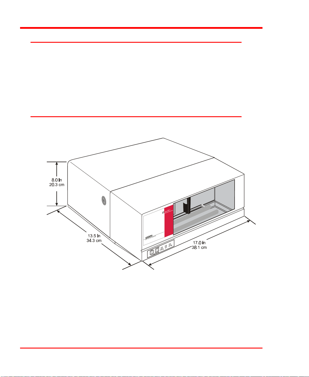
p Space requirements: The DAT Autochanger has a footprint of 17" x 13.5". You
must allow adequate clearance to the rear and sides (2 inches minimum) to allow
airflow and enough room at the front to open the door (which stands 8" high and
is hinged at the bottom).
p Host computer system: We assume that you are familiar with your host computer
system. The DAT Autochanger is controlled by backup software running on your
2 Getting Started
Page 15

host computer. The backup software, SCSI controller card (if required), and any
additional, or different, SCSI interface cable(s) must be purchased separately.
p Mode of operation: You must know whether the DAT Autochanger will be
operating in sequential access or random access mode. For additional
information refer to the Modes of Operation section later in this chapter.
p Necessary tools: No special tools are required to install the DAT Autochanger. If
you are also installing a SCSI host adapter card, refer to the installation manual
for your host adapter.
Unpacking and Inspecting
Caution
If the temperature of the operating environment differs from that
of the storage environment by 10°C (18° F) or more, let the
DAT Autochanger acclimate to the ambient one hour for every
10° C of difference.
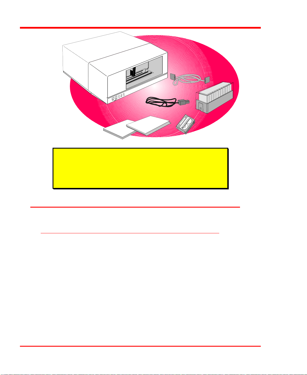
The DAT Autochanger packaging materials have been carefully designed to protect
it from shock, vibration, and moisture. The DAT Autochanger should remain in the
packaging until it is ready to be installed. All original materials should be saved in
case you need to move or ship the system in the future. Unpack all items from the
carton.
Getting Started 3
Page 16
Caution
You must ship the DAT Autochanger in the original or
equivalent packaging materials or your warranty may be
invalidated.
Equipment Description
The DAT Autochanger
The DAT Autochanger is a fully automated, high performance, high capacity, mass
storage system designed with a removable data cassette magazine. It is composed of
a standard DAT DDS drive and DAT Autochanger-unique hardware (robotics) that
are controlled by application software running on your host computer.
The DAT Autochanger provides unattended, fully automatic, sequential access or
random access to data stored on the cassettes. The robotics moves the DAT (digital
audio tape) cassettes into and out of the DAT drive as needed. High data reliability is
achieved through read-after-write and additional third-level error detection and
correction circuitry (typical error rates are less than one bit in 1015).
4 Getting Started
Page 17
The heart of the DAT Autochanger is the DAT drive. The DDS (Digital Data
Storage) format uses helical scan technology, originally used in digital audio
recorders, and adapts it for computer data storage. When equipped with a DDS 3
drive, the DAT Autochanger provides up to 24 GB (at an average 2:1 compression)
of removable, highly reliable data storage on a low cost, pocket-sized 125 meter
DAT cassette. A fully loaded twelve-cassette magazine will provide a storage
capacity of 288 gigabytes (at an average 2:1 compression.)
The DAT Autochanger may be used with any computer that supports SCSI, SCSI-2,
or SCSI-3 devices.
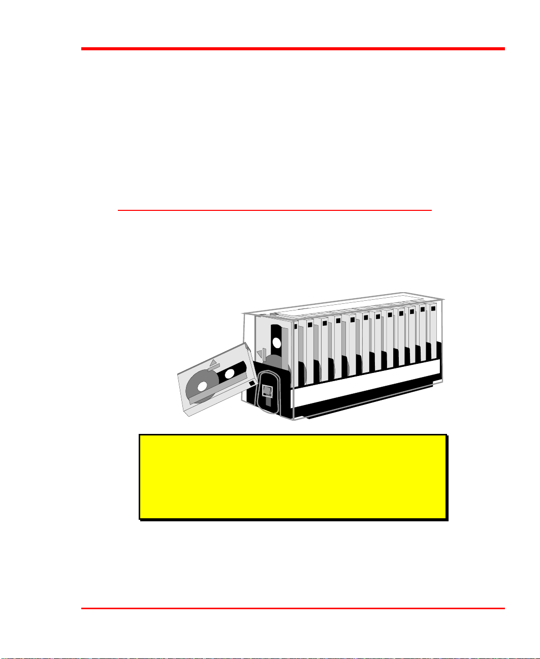
Magazine
The magazine for the DAT Autochanger holds twelve DDS cassettes. It includes a
clear dust cover to protect the cassettes and for ease of storage. The following
illustration shows a DDS cassette and a filled magazine with the cover in place.
Note
adic strongly recommends that you use adic approved DDS
cassettes only. Do not attempt to use "audio-grade" media (such
media can damage the head and tape handling parts – voiding
your warranty).
Getting Started 5
Page 18
Media
The DAT Autochanger uses DDS data cassettes. Never use DAT audio grade
cassettes, because the media is not certified for data storage. Also, DAT audio grade
cassettes have a different mechanical specification, which can cause them to jam in
the drive mechanism.
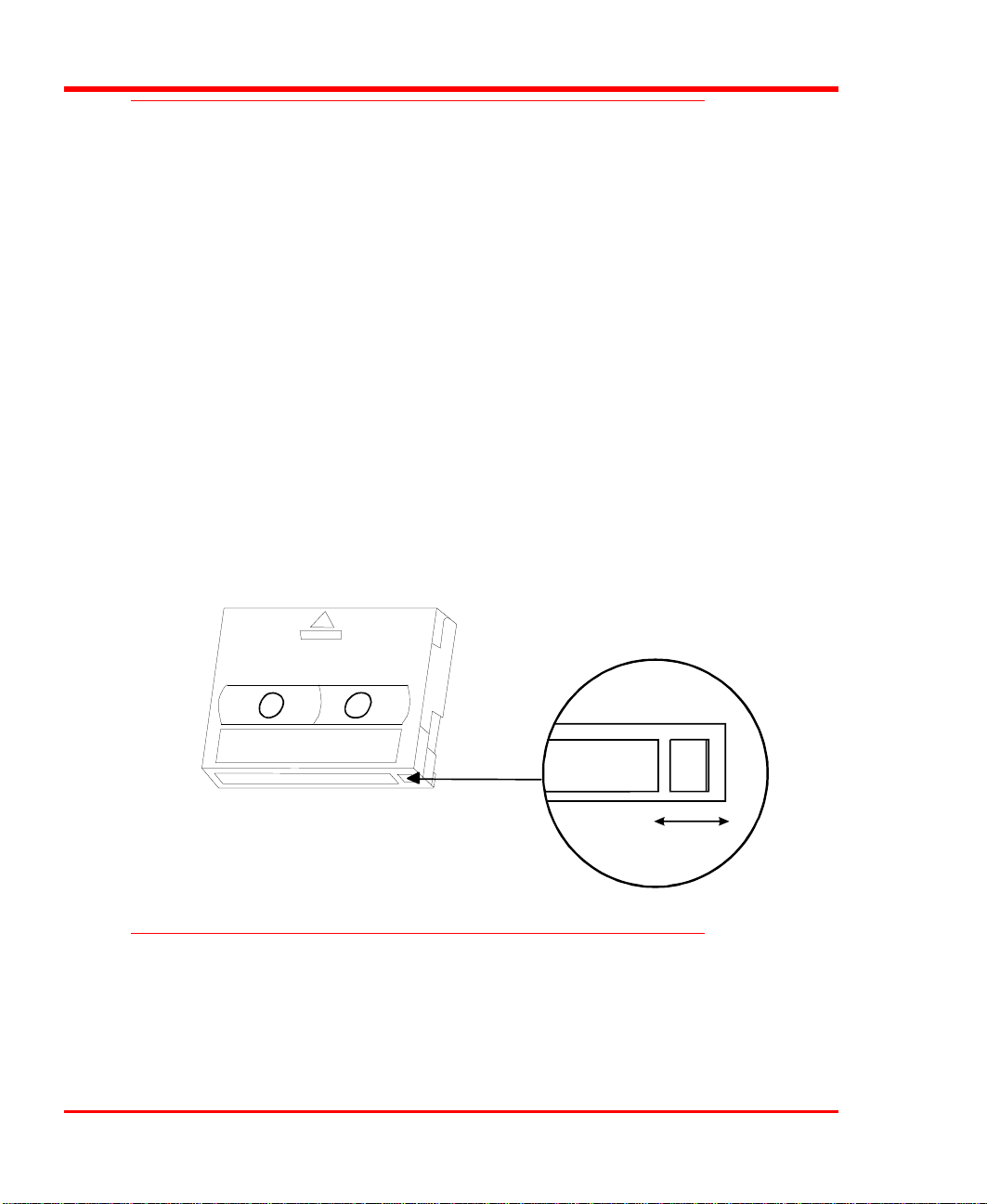
Before inserting the cassette into the magazine check the position of the write-protect
switch. Set all tabs to the enabled position (unless a tape contains data that you don't
want erased). (The write-protect switch enables or disables the ability to write [or
delete] files on the data cassette.)
To write-protect the data cassette, move the write-protect switch away from the edge
of the data cassette. If the write-protect hole is open, the cassette is write-protected
and cannot be written to (or erased).
To write-enable the data cassette, move the write-protect switch toward the edge of
the data cassette, as shown. If the write-protect hole is closed, the cassette is write
enabled and can be written to or erased. Use a ballpoint pen or similar instrument to
move the write-protect switch.
Cleaning Cassette
The tape head should be cleaned after every 8 to 10 hours of actual tape motion in
the drive or when the Media Caution signal is displayed. A 20-use cleaning cassette
(adic 39-1028-01) is shipped with your DAT Autochanger. Discard it after 20 uses
6 Getting Started
Page 19

and replace it with the same or equivalent type cassette. See Cleaning the Drive
Head, later in this manual.
Note
After 24 hours of head-tape motion since the last cleaning the
LEDs will flash amber in unison. This flashing in unison is the
Media Caution signal.
Modes of Operation
The DAT Autochanger has two modes of operation. When used in random access
mode the DAT Autochanger allows your backup software to access any cassette in
the magazine randomly. This permits you to logically divide cassette usage to satisfy
particular storage needs. For example, you may assign one or more cassettes to
specific data functions such as certain directories or network servers, or you may
assign cassettes to individual users. Sequential access mode operates the DAT
Autochanger as a stacker. Your backup software will write the data to each of the
cassettes sequentially starting with the first one.
Getting Started 7
Page 20
Select or Confirm Random Access Mode
To confirm that the random access mode is selected, check to be sure that the mode
selection jumper is installed on the mode selection pins on the back of the control
module panel (your DAT Autochanger is shipped from adic with the jumper
installed).
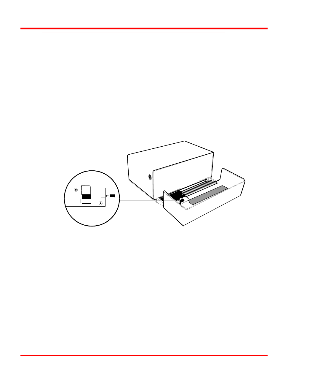
p Open the DAT Autochanger door. Locate the small circuit board next to the left-
hand hinge. The mode selection pins are located on the underside of the board on
the right side. A jumper should be installed over the pins.
To select the random access mode if the jumper has been removed, simply install the
jumper over the pins.
Select or Confirm Sequential Access Mode
To confirm that the sequential access mode is selected, check to be sure that the
mode selection jumper is not installed on the mode selection pins on the back of the
control module panel (your DAT Autochanger is shipped from adic with the jumper
installed).
p Open the DAT Autochanger door. Locate the small circuit board next to the left-
hand hinge. The mode selection pins are located on the underside of the board on
the right side. The jumper should not be installed over the pins (see Figure 6).
To select the sequential access mode if the jumper has been installed, simply remove
the jumper from the pins.
8 Getting Started
Page 21

SCSI
SCSI is the acronym for Small Computer System Interface. The interface is a
combination of an 8-bit parallel bus (hardware) and a command set (software). SCSI
allows you to connect up to seven SCSI devices to any host computer.
The SCSI interface is transparent to the host computer. The computer only needs to
ask for data from a device, or ask to send data to a device. The SCSI interface
performs the task of moving the data.
SCSI ID
The SCSI standard specifies that up to seven devices may be connected to a single
SCSI channel. It does this by specifying seven IDs (addresses), one for each device.
The DAT Autochanger, when operated in random access mode, requires two IDs;
one for the DAT drive, and one for the robotics. The SCSI ID for the drive has been
preset at the factory to "0" and the ID for the robotics has been preset to "3". Your
backup software that controls the DAT Autochanger determines the proper IDs for
the drive and robotics. Refer to the User's Manual provided with your software for
the correct IDs.
The SCSI ID switches are located on the rear of the DAT Autochanger. They are the
small red rotary switches to the left of the SCSI connectors. You may change the IDs
by using a small flat-blade screwdriver to move the switch to the proper position.
When operated in sequential access mode the robotics section of the DAT
Autochanger does not appear on the bus, and therefore does not require a SCSI ID.
Preparing the Host Computer System
Power Off the Host Computer
p Turn off the power switch. Unplug the cord from the AC outlet.
Getting Started 9
Page 22

Note
The host computer system normally is the network server.
Confirm and/or Install the SCSI host interface
The DAT Autochanger must be connected to either an integrated SCSI host or a
SCSI interface (host adapter) card installed in the computer – either directly to the
SCSI connector on the card or as part of an existing SCSI chain. The SCSI interface
must be installed before you connect the DAT Autochanger. Refer to the instructions
supplied with the card.
Now you are ready to connect the DAT Autochanger to your host computer. Follow
the instructions provided in the next chapter.
System Software
A variety of backup and data storage software is available for use with the DAT
Autochanger. Please check with adic Sales or the Customer Assistance Center if
you have a question on the compatibility of a particular software package.
10 Getting Started
Page 23

Chapter
Connecting the DAT Autochanger
This Chapter. . .
p provides instructions for physically connecting your DAT
Autochanger to your host system.
2
11
Page 24
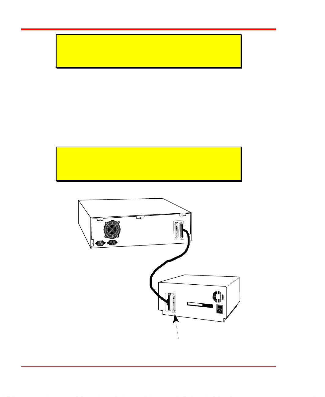
Connecting the Interface Cables
First make sure the interface cable you are using has the appropriate connectors on
each end. If the host computer's SCSI connector is different from that on the DAT
Autochanger, you will need to obtain a different cable than the one supplied with the
unit. Consult your dealer or adic Customer Assistance if you need help. Connect the
interface cables as shown in the following illustration and explained in the following
steps:
Note
The interface cables must be shielded – adic can supply you
with the correct type(s).
p Check that the power switches on both the DAT Autochanger and the host
computer are off.
p Attach the 50-pin end of the SCSI interface cable to either connector on the rear
of the DAT Autochanger. Press firmly and secure the bail locks.
Host Computer
SCSI Interface Cable
12 Connecting the DAT Autochanger
DAT Autochanger
Terminator
Page 25

Note
Terminato
r
The bail locks at both ends of the SCSI cable must be securely
fastened in order for the DAT Autochanger to communicate
properly with the computer.
p Plug the other end of the SCSI cable into the external SCSI connector on your
host computer. Secure the bail locks firmly.
p If the DAT Autochanger is the only SCSI device you are installing, insert an
external single-ended terminator into the second SCSI connector. If you plan to
connect another SCSI device on the same SCSI channel, see the next section.
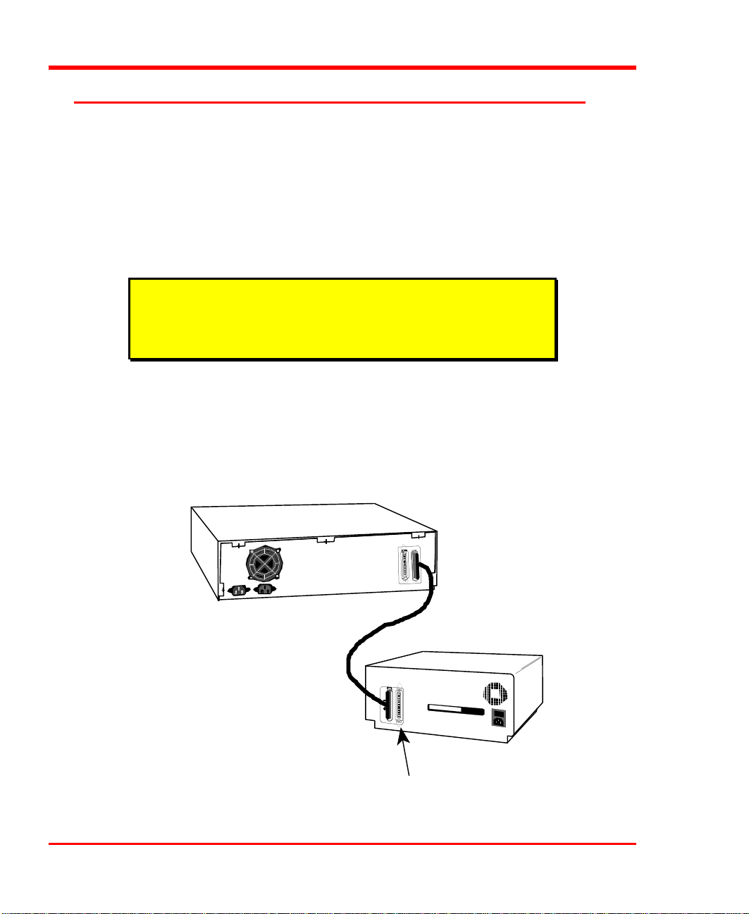
Connecting More Than One DAT Autochanger
If installing additional DAT Autochangers on the same SCSI channel, attach each
subsequent unit to the previous unit with an interface cable. Make sure all cables are
properly secured. You can install up to seven devices to each SCSI channel, but each
DAT Autochanger may represent more than one SCSI device.
Host Computer
SCSI Interface Cable
DATAutochanger
Connecting the DAT Autochanger 13
Page 26

Note
When counting SCSI devices, keep in mind that a DAT
Autochanger can contain up to two devices (the DAT drive and
the robotics). Don't forget to include in your count other devices
on the SCSI channel, (i.e., a tape unit, an additional hard drive,
etc.).
Each DAT Autochanger unit contains more than one SCSI device and may require
more than one SCSI ID (depending on the mode of operation). The first chart below
shows the different DAT Autochanger configurations and the number of SCSI IDs
required. The second chart illustrates how many DAT Autochanger units you can
attach to one SCSI channel (if there are no other devices on the channel).
Number of SCSI IDs Required
Sequential Mode Random Mode
1 2
Maximum DAT Autochangers on one SCSI Channel
Sequential Mode Random Mode
7 3
Powering on the System
p Plug the AC power cord into the connector on the rear of the DAT Autochanger.
p Plug the AC power cord from the DAT Autochanger into a grounded electrical
outlet.
p Plug the AC power cord from your host computer into a grounded electrical
outlet.
p Turn on the DAT Autochanger power. Turn on the host computer power.
14 Connecting the DAT Autochanger
Page 27

Installing the Backup Software
Note
This is the software that operates the DAT Autochanger, not the
data being transferred to the DAT Autochanger cassettes. Two
examples of backup software are Cheyenne's ARCserve and
Legato's Networker.
Refer to the installation instructions provided with your backup software and install
the software on your host computer.
After you have completed installation of the DAT Autochanger and the software,
you should run any diagnostic test(s) supplied with the software to make sure your
unit is operating correctly.
Connecting the DAT Autochanger 15
Page 28

Blank Page
16 Connecting the DAT Autochanger
Page 29

Equipment Description
This Chapter. . .
p explains the switches, indicators and connectors on the front and
rear of the DAT Autochanger.
Chapter
3
p describes the various functions available via the front panel
buttons.
17
Page 30

For the most part, once your DAT Autochanger has been connected to your host
computer system and the software has been installed, the DAT Autochanger is ready
for use. Just turn on the power switch, place a magazine on the carriage and press the
LOAD button on the front panel.
Front Panel Switches and Indicators
Switches and indicators on the front of the DAT Autochanger are shown in the
following illustration.
18 Equipment Description
Page 31

Power LED (green)
Lights when the power is on. It also reports error conditions
(through a blinking sequence).
Busy LED (green)
Lights whenever the drive is active. It also reports error
conditions (through a blinking sequence in conjunction with
the Power LED).
Note
The Power and Busy LEDs are used to indicate that an error has
occurred with the DAT Autochanger. Refer to Chapter 5,
Troubleshooting and Diagnostics for descriptions of the error
codes displayed by the Power and Busy LEDs.
Locked LED
(green)
Lights whenever the LOAD and UNLOAD buttons are
disabled. This occurs when a cassette is in the drive, or if
commanded from the system software. This LED blinks
when an unload operation is pending in sequential access
mode.
Note
The DAT Autochanger uses the LOAD function to detect
reversed cassettes or the absence of a cassette.
LOAD
Pressing this button initiates a load magazine sequence − the
DAT Autochanger will check the cassettes in the magazine
(making note of empty spaces) and that all cassettes present
can be inserted in the drive correctly.
UNLOAD
Press this button to initiate an unload sequence − the DAT
Autochanger will return the magazine to the unload position.
Caution
Never attempt to remove a magazine unless it is in the unload
position. You may damage the pick arm.
Equipment Description 19
Page 32

Rear Panel Switches and Connectors
SCSI connectors
Rear panel switches and connectors are shown in the following illustration.
Power Switch
AC Power
Connector
Power Switch
CHANGER
SCSI
ADDRESS
DRIVE
Turns on the AC power.
Plug the AC power cord into this connector.
DAT Autochanger
AC Power Connector
20 Equipment Description
SCSI Connectors
Connections for interface cable that connects DAT
Autochanger to host computer, to other DAT Autochangers
and/or to other devices.
SCSI ID Selectors
Selects the SCSI ID for the drive and robotics (CHANGER).
Note
SCSI ID changes do not take effect until you cycle power on the
DAT Autochanger.
Page 33

Operation and Maintenance
This Chapter. . .
p describes normal operating features of the DAT Autochanger
p provides details on the media and magazine
Chapter
4
p explains normal maintenance procedures
21
Page 34

The DAT Autochanger is a highly sophisticated unit composed of a DAT drive and
the electro-mechanical robotics that control the drive, magazine, and media. No
modifications have been made to the DAT drive. The built-in drive warning lights
function as the manufacturer has specified.
Very little routine maintenance is required – apart from cleaning the heads after
approximately 8 to 10 hours of use or when the Media Caution shows (see Cleaning
the Drive Head later in this chapter) on the drive LEDs.
Note
The drive warning lights are located on the bottom front of the
drive, to see them you must look down through the front door
window.
Inserting the Data Cassettes into the Magazine
The magazine for the DAT Autochanger holds 12 DAT cassettes. It includes a clear
dust cover to protect the cassettes and for easy storage. See Figure 11. Insert each
cassette into a slot of the magazine making sure that the write-protect tab is toward
the top, facing the closed side of the magazine.
adic strongly recommends that you use data-grade DDS media
only. Do not attempt to use "audio-grade" (DAT) media (such
media can damage the heads and tape handling parts).
22 Operation and Maintenance
Note
Page 35

The open side of the magazine faces the DAT Autochanger. Make sure each cassette
touches the bottom floor of the magazine. The cassettes will fit firmly in the
magazine due to the spring holder (the button-like object on the side of the cassette
slot). The spring holder will keep each cassette in place even if the magazine is
turned upside down.
Do not use wrap-around labels on the individual cassettes. Most labels use a
removable adhesive and have a tendency to curl or tear after multiple uses. This can
jam the movement of the DAT Autochanger.
Note the following:
• Store magazines (and data cassettes) in a dry, cool environment. Keep the
dust cover on the magazine.
• Never reset or power down your host computer or DAT Autochanger while a
function is in process or a tape is moving. In addition to a tape with missing
or corrupted data, you may also get tape run-on within the drive (a condition
that can produce internal contamination requiring extra cleaning).
• If a power outage occurs during a back-up sequence, restart your backup
from the beginning.
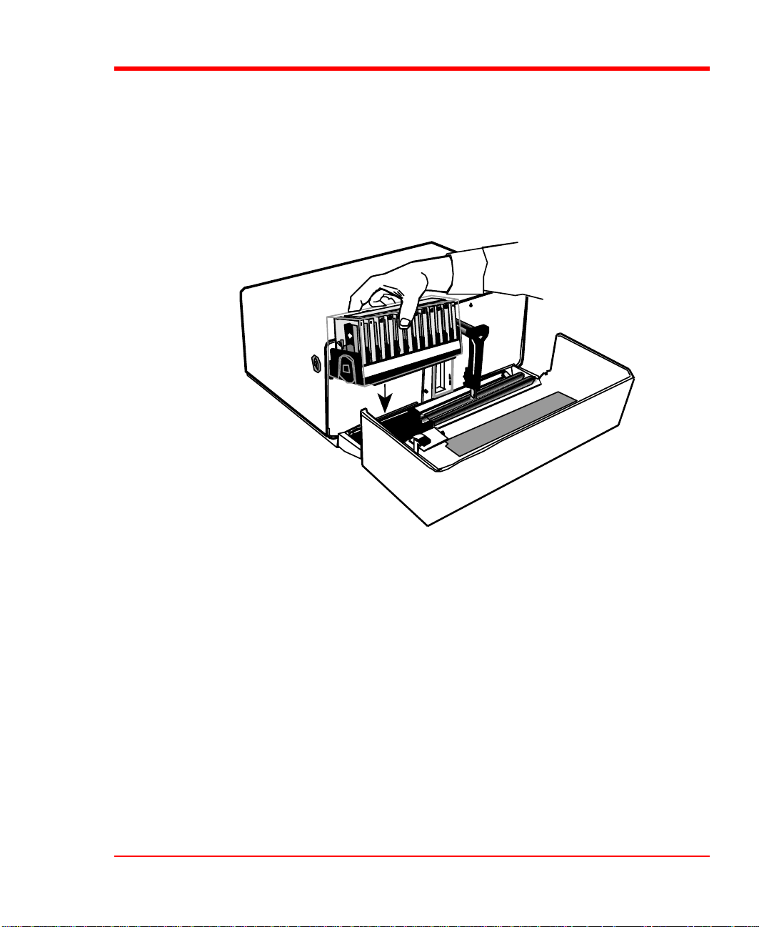
Inserting the Magazine into the DAT
Autochanger
p Open the DAT Autochanger door.
Note
The magazine should be inserted and removed from the DAT
Autochanger with the magazine cover on.
p Holding the magazine by the cover, use two hands to place it on the carriage
platform. Make sure that the two projections on the bottom of the magazine fit
into the two holes on the carriage platform.
Operation and Maintenance 23
Page 36

p Press down gently while rocking the magazine from side-to-side until it snaps
into place. Remove the cover by pressing in on the middle of both ends (where it
is labeled PUSH ) and lifting upwards.
Loading the Magazine
Once you have placed the magazine on the carriage, the DAT Autochanger must
initiate a loading process. During this procedure the DAT Autochanger checks and
maps the position of each cassette and makes sure that all cassettes are inserted into
the magazine correctly. If you are using the sequential access mode the DAT
Autochanger inserts the first cassette into the drive.
p Make sure the magazine is placed correctly on the carriage.
p Close the door and press LOAD. The DAT Autochanger will initiate the loading
procedure.
Note
The door must be closed before the LOAD or UNLOAD functions will
activate.
24 Operation and Maintenance
Page 37

Note
In the sequential access mode, if you press UNLOAD before the
DAT Autochanger has finished loading the magazine, the
robotics will finish mapping and checking the cassettes and then
move the magazine to the unload position (the far left) without
inserting a cassette into the drive.
In random access mode, if the DAT Autochanger has not
finished loading the magazine, pressing UNLOAD will have no
effect.
Attempting to Load the Magazine with a
Cassette Already in Drive
If you attempt to load the magazine while there is a cassette in the drive, the DAT
Autochanger will attempt to load the cassette. Upon finding there is a cassette in the
drive, the DAT Autochanger will stop the load and flash an error message (see
section titled DAT Autochanger Warning Lights in Chapter 5 for a description of
error messages). In this case, proceed as follows:
If you are using sequential access mode
p Press and hold LOAD and UNLOAD simultaneously until all three front panel
lights flash Then proceed as noted below for random access mode.
If you are using random access mode
p Press UNLOAD. This will unload the magazine.
p Press LOAD and UNLOAD simultaneously. This will move the gripper arm
away from the drive.
p Open the DAT Autochanger door. Press the eject button on the DAT drive. It
may take 30 seconds or more for the drive to eject the cassette.
Operation and Maintenance 25
Page 38

Note
The drive eject button is located on the top front of the drive. Look
beyond the arm to the drive.
p Remove the cassette manually. You can place it back in the magazine, if desired.
p Close the DAT Autochanger door. You can now reinitiate the load procedure.
Removing the Magazine from the DAT
Autochanger
If you are using sequential access mode
Before physically removing the magazine from the carriage, you must first initiate
the UNLOAD procedure.
p Press UNLOAD and wait until the carriage moves the magazine to the far left of
the DAT Autochanger.
p Place the cover on the magazine by pressing gently on the top until you hear it
snap into place.
26 Operation and Maintenance
Page 39

p Remove the magazine by using two hands to grasp the magazine and pull up and
toward you.
p Store the magazine in a cool dry place.
If you are using random access mode
When operated in random access mode, the software usually commands the DAT
Autochanger to unload a magazine (or individual cassette). The LOCKED LED is
intended to protect the system against unauthorized user intervention. When the
LOCKED LED is on, the DAT Autochanger ignores the LOAD and UNLOAD
buttons on the front panel. Use your system software to issue the UNLOAD
command.
Removing the Magazine with a Cassette in
Drive
If you wish to remove the magazine but there is a cassette in the drive, do the
following:
p Cycle power on the DAT Autochanger (turn the power switch off and then back
on after a few seconds have passed).
p Open the DAT Autochanger door.
p Press the eject button on the drive.
p It will take thirty seconds or more for the drive to eject the cassette.
p Close the door of the DAT Autochanger. Press the UNLOAD button to retrieve
the cassette and move the magazine to the unloaded position.
p Place the cover on the magazine and remove it as noted previously.
Loading an Individual Cassette
If for some reason you need to use a single cassette, you can load it manually (this
operation is the same as loading a cleaning cassette).
Operation and Maintenance 27
Page 40

p Unload the magazine by pressing UNLOAD. The magazine will move
completely to the left.
p Press LOAD and UNLOAD simultaneously. This will cause the gripper arm to
move out from the drive opening.
p Open the DAT Autochanger door after the arm is fully extended.
p Insert the cassette into the drive opening with the write-protect tab up. Apply
moderate, steady pressure to the cassette. The drive will take approximately 20
seconds to load the cassette.
p Close the DAT Autochanger door and initiate desired program.
p If the drive does not eject the cassette when the program is finished, open the
DAT Autochanger door (the gripper arm should still be fully extended) and press
the drive eject button. It will take about 30 seconds for the drive to eject the
cassette.
Removing a Cassette from the Magazine
The data cassettes are easily slipped into and out of the magazine slots. To remove a
cassette, simply grasp it with two fingers and pull up. Make sure each cassette is
labeled so you know the contents, and their correct position in the magazine.
Storing the Magazine
Store magazines in a dry, cool environment. Always keep the dust cover on the
magazine.
The removable magazine allows for long-term archiving or off-site safety storage of
groups of cassettes.
You can duplex multiple DAT Autochangers so your system can mirror data backups
on each separate unit. With duplexing you have real time data assurance and the
ability to remove one magazine for off-site storage while the other remains for on-
line data access.
28 Operation and Maintenance
Page 41

Cleaning the Drive Head
Caution
Using cloth swabs, cotton swabs, or cleaning agents, will void the
warranty. Use only a DDS cleaning cassette.
Clean the drive heads and tape path after 8 to 10 hours of tape motion (about once a
week under typical use). This cleaning frequency does not depend on the format, in
which you write and read data. However, if you are using the DAT Autochanger in a
particularly dirty environment, or if you operate it infrequently, we suggest that you
clean it more often. The drive keeps track of tape motion hours internally. When 24
tape motion hours have elapsed since the last cleaning, both drive front panel LEDs
will flash amber in unison (Media Caution Warning). We urge you to clean the drive
as soon as possible after the LEDs begin flashing.
Caution
Only cassettes labeled "DDS Cleaning Cartridge" should be used. Use
of Audio DAT cleaning cassettes will cause excessive wear to the drive
heads.
Drive LEDs
Operation and Maintenance 29
Page 42

Caution
Use only an approved cleaning cassette to clean the heads. To prevent
contamination of the drive and damage to the heads, do not use the
cleaning cassette for more than the number of cleaning cycles specified
on the cassette label. Discard the cleaning cassette after you have used
it the specified number of cleaning cycles. Do not attempt to rewind the
material in the cleaning cassette and reuse it.
Please follow these cleaning directions carefully to assure that no damage will occur
to the drive, the DAT Autochanger, or media.
p Unload the magazine by pressing UNLOAD. The magazine will move
completely to the left.
p Press LOAD and UNLOAD simultaneously. This will cause the gripper arm to
move out from the drive opening. Open the DAT Autochanger door after the arm
is fully extended.
Note
Some application packages may allow a magazine slot to be used for a
cleaning cassette and automate its use. Refer to your application
software manual.
p Insert the cleaning cassette into the drive opening. The drive will load the
cassette and automatically begin the cleaning process. The cleaning cycle takes
approximately 15 seconds to complete.
30 Operation and Maintenance
Page 43

Note
If there are no more cleaning cycles remaining for the cleaning cassette,
the drive will eject it immediately after insertion.
p When the cleaning is finished the drive will automatically eject the cassette.
Remove the cleaning cassette and write the date on the label so you have a
record of how many times it has been used and when.
p To confirm that a cleaning was performed, look at the LEDs on the front of the
drive. If the cleaning cycle was successful, the LEDs will be off. If the cleaning
cycle was not performed (because the cleaning cassette was at its end-of-tape),
the LEDs will continue to flash.
p Place the magazine onto the carriage. Close the DAT Autochanger door. Press
LOAD to initiate the load procedure.
The DAT Autochanger is once again ready for use.
Cleaning the Enclosure
The outside of the enclosure can be cleaned with a damp towel. If you use a liquid
all-purpose cleaner, apply it to the towel. Do not directly spray the enclosure.
Operation and Maintenance 31
Page 44

Blank Page
32 Operation and Maintenance
Page 45

Chapter
Troubleshooting and Diagnostics
This Chapter. . .
p contains some general suggestions to aid you in solving
problems – should you ever run into them.
5
p includes information on warning lights.
33
Page 46

DAT Autochanger Warning Lights
If any component of the DAT Autochanger is not communicating correctly, the
POWER LED and the BUSY LED will flash a warning message code.
The lights will blink in a sequence indicating a two-digit number. The POWER LED
flashes in slow blinks to indicate the left digit, after which the BUSY LED flashes in
fast blinks to indicate the right digit. For example, an error message code of 37
would cause the POWER LED to flash three slow blinks after which the BUSY LED
will flash seven fast blinks.
A list of user-correctable error message codes appears on the next page. If the error
message code your DAT Autochanger is indicating is not on this list, please call the
adic Customer Assistance Center for help.
In all cases, after removing the cause of the problem (or if you can't find a cause)
press and hold LOAD and UNLOAD simultaneously to reset the DAT Autochanger.
If the error message is not listed, try to reset the DAT Autochanger by pressing
LOAD and UNLOAD simultaneously. If the DAT Autochanger does not reset, or if
you get the same error again, call the adic Customer Assistance Center, at: (206)
883-4357, and be prepared to tell them what the error message is – and what the
conditions are.
34 Troubleshooting and Diagnostics
Page 47

Error Message Codes
Code
07 Source empty Reset DAT Autochanger and reload magazine. Sequential
10 Cassette present − beam
12 Illegal SCSI ID Change SCSI ID to valid ID using the rear
15 Unexpected pick arm out
16 Unexpected magazine
21 No arm out position
23 Unexpected cassette
25 Unable to retrieve cassette Check that the cassette sliding door is not
32 Load cassette failure Check to make sure cassette is inserted in the
37 Reverse cassette failure Make sure that the cassette is inserted in the
Meaning/Problem Action Mode of
Operation
intermittently blocked
position
home position
detected
sensor block
Check that cassette present sensor is not
inadvertently blocked by foreign object.
panel switch.
Check to see if there is something obstructing
arm. Remove it and reset DAT Autochanger.
Check to see that magazine is seated correctly
and that nothing is obstructing its movement.
If there appears to be no obstruction, unload
magazine and reload it from front panel.
Check to see if there is something obstructing
arm. Remove it and reset DAT Autochanger.
Check for foreign material obstructing
cassette-present beam and remove as
necessary. Check to see that magazine is
seated correctly and that nothing is obstructing
its movement. If there appears to be no
obstruction, unload magazine and reload it.
staying open.
magazine correctly and that nothing is
obstructing it from moving into the drive.
magazine correctly. All the write-protect tabs
should be facing you at the upper right.
Sequential
Random
Sequential
Sequential
Sequential
Sequential
Sequential
Sequential
Sequential
Troubleshooting and Diagnostics 35
Page 48

Drive LEDs
The drives used in the DAT Autochanger employ front panel LEDs to indicate SCSI
interface activity, drive fault conditions, and cartridge status. The following
illustration shows a close-up of the Sony SDT5000 drive and the location of the
warning lights. Refer to the following tables for descriptions of the methods
employed by different drives to indicate activity, status, and fault conditions.
Drive LEDs
36 Troubleshooting and Diagnostics
Page 49

Hewlett Packard C1533A/C1537A
TAPE LED (bottom) CLEAN LED (top) MEANING
Flashing green (½ sec
Off Cartridge activity — load or unload
on, ½ sec off)
Fast flashing green (¼ sec
on, ¼ sec off)
Steady green Off Cartridge loaded, drive online
Off Flashing amber (½ sec on,
Off Steady amber Drive fault
Flashing green (½ sec on,
½ sec off)
Off SCSI activity — read or write
Media Caution Signal
½ sec off)
Off Self-test in progress
Troubleshooting and Diagnostics 37
Page 50

Sony SDT-5000/SDT-7000/SDT-9000
Busy LED (Top) Tape LED (Middle) Status LED
MEANING
(Bottom)
Off Off Off No cartridge present/no activity
On Off Off SCSI activity — read or write
Fast flashing (¼ sec on,
¼ sec off)
Fast flashing (¼ sec on,
¼ sec off)
Off On Fast flashing (¼ sec on,
Off On Off Cartridge loaded/no activity
On On Off Cartridge loaded/SCSI activity
Fast flashing (¼ sec on,
¼ sec off)
* On On Cartridge loaded/write
* Long, slow flashing (3½
Long, slow flashing (3½
sec on, ½ sec off)
* * Long, slow flashing (3½
* * Flashes once for ¼ sec
* * Flashes twice once for ¼
Flashes once for ¼ sec
then stays off for 1 sec
* Flashes once for ¼ sec
Fast flashing (¼ sec on,
¼ sec off)
Fast flashing (¼ sec on,
¼ sec off)
On Off Cartridge loaded/SCSI and
sec on, ½ sec off)
* * High humidity detected
* * Waiting for reset
then stays off for 1 sec
Off Drive loading/unloading
On Drive loading/unloading with
cartridge write protected
Cleaning cartridge at end of
¼ sec off)
* Media Caution Signal —
sec on, ½ sec off)
then stays off for 1 sec
sec then stays off for 1
sec
* Waiting for eject
media (no cleaning cycles
remaining)
drive activity
protected
excessive errors detected
Media Caution Signal —
predetermined number of tape
head motion hours reached
Drive mechanical failure
detected
Drive circuitry failure detected
38 Troubleshooting and Diagnostics
Page 51

Environmental Considerations
For best performance of your DAT Autochanger, please observe the following
guidelines:
p If you expose cassettes to temperatures outside the operating limits – 40-113°F
(5-40°C) – stabilize them by leaving the cassettes in the operating temperature
for a minimum of two hours before you use them.
p Avoid temperature problems by ensuring that the DAT Autochanger's side and
rear are not obstructed, so that the drive has adequate ventilation.
p Position the DAT Autochanger where the temperature is relatively stable (i.e.,
away from open windows, fan heaters and doors).
p Avoid leaving cassettes in severe temperature conditions, for example, in a car
standing in bright sunlight.
p Avoid transferring data (reading from and writing to cassettes) when the
temperature is changing by more than 15°F (10°C) per hour.
When You Call adicadic Customer Assistance
Before calling adic Customer Assistance, follow these steps – which will help you
take full advantage of your call:
p Review all documentation carefully. (Experience has demonstrated that most
questions are answered in your documentation.)
p Be prepared to explain whether the software or hardware has worked properly at
anytime in the past. Have you changed anything recently?
p Pinpoint the exact location of your problem, if possible. Note the steps that led to
the problem. Are you able to duplicate the same problem or is it a one-time
occurrence?
p Note any error messages displayed on your PC screen or file server. Write down
the exact error message.
p If at all possible, call while at your computer, with adic's system installed and
turned on.
p If running on a network, have all relevant information available (i.e., type,
version #, network hardware, etc.).
Troubleshooting and Diagnostics 39
Page 52

p Be prepared to provide:
• Your name and your Company's name
• Model number
• Serial number of unit (located on the rear face by the power switch)
• Software version numbers
device driver
archive/restore
• Hardware configuration, including firmware version, date and number.
• Type of PC, DOS version, clock speed, RAM, network type, network ver-
sion, and any special boards installed
• Type and brand of media
• A brief description of the problem
• Where you purchased the adic system
Having this information available when you call for customer assistance will enable
adic to resolve your problem in the most efficient manner possible. Then call the
Customer Assistance line.
Note
Call adic Customer Assistance at: (206) 883-4357.
If you wish, you may contact adic Customer Assistance through the
adic BBS at: (206) 883-3211, or by leaving Internet E-mail at:
support@adic.com.
40 Troubleshooting and Diagnostics
Page 53

Return for Repair RMA (Return Merchandise
Authorization)
When you and adic Customer Assistance have determined that you need an RMA
(see section, When You Call adic Customer Assistance), be prepared with the
following information:
Note
Be sure you have tried all trouble shooting techniques in the various
manuals before calling.
• Model number, serial number, and a brief, descriptive explanation of the
problem.
• Complete address information (be sure you give any mail stops or special
codes at the time the RMA is issued).
• If the item is NOT in warranty, you will be charged for the repairs.
Therefore, the Customer Assistance personnel will need a P.O. number at the
time the RMA number is issued. Until credit information can be obtained by
our accounting department, the system may be shipped back COD to firsttime customers.
• It is also necessary to send the complete system, including interface card or
controller, interface cables, and the unit. A defective external component
and/or the drive itself may have caused problems.
Current labor rates will be quoted at the time the RMA is issued.
Note
Following this RMA procedure will expedite handling, repairs and the
return of equipment.
Troubleshooting and Diagnostics 41
Page 54

Blank Page
42 Troubleshooting and Diagnostics
Page 55

Glossary
Appendix
A
This Appendix. . .
p contains terms and definitions of expressions commonly used
with the DAT Autochanger and the DDS drive.
43
Page 56

byte
8 bits or one character
C
cassette
cleaning
cassette
cm
DDS
4mm DDS
data
cassette
FCC
GB
HSM
Celsius (Centigrade)
A storage medium item. A cassette is sometimes called a tape or
cartridge and is capable of storing vast amounts of magneticallywritten data. Some cassettes can store more than 16 gigabytes of
data.
Media used to clean the drive heads and tape path.
centimeter (0.3937 inches)
Digital Data Storage is the original industry-standard data
interchange recording format that supports the use of DAT for
computer applications. The DDS format is an overlay to the basic
DAT audio format.
Media used in the DAT Autochanger. It is a data-quality 4mm metalparticle cassette. These cassettes require no formatting or other
media conditioning before use. These cassettes must be adic
approved.
Federal Communications Commission
gigabyte (1 GB = 1,024 Megabytes)
Hierarchical Storage Management – a system where different types
of storage medium are used based on cost and time efficiency. For
example, for fastest access, data is usually stored on a local hard
drive. If you have a very large file that is needed occasionally, you
may store it on a tape in a DAT Autochanger magazine, or on an
optical drive. In an HSM system, the data source should be
transparent to the user.
Hz
initiator
KB
LED
44 Glossary
Hertz (replacement for "cycles-per-second").
A host computer system that requests an operation to be performed
by a target device.
Kilobyte (1 KB = 1,024 bytes)
Light Emitting Diode, a commonly used display that glows when
supplied with a specified voltage.
Page 57

load
The process where the DAT Autochanger checks each slot to see if a
cassette is physically present, and if so, whether the orientation of
the cassette in the magazine is correct. It also places the magazine in
position for the first cassette to be inserted into the drive. In
sequential mode, the first cassette is physically inserted into the
drive.
magazine
MB
mm
Random
Access
Mode
RMA
RMA
number
SCSI
SCSI ID
The item that holds the tape cassettes for use by the DAT
Autochanger. The magazine holds 12 cassettes. The magazine also
provides long-term covered storage of cassettes.
megabyte (1 MB = 1,024 Kilobytes)
millimeter (0.03937 inches)
Gives the software the ability to communicate with the robotics in
such a way as to be able to access the cassettes in the magazine (and
data on the cassettes) in any order.
Return Merchandise Authorization.
An identifying number given to a customer who needs to return
equipment for repair, whether under warranty or not.
Small Computer System Interface. An industry standard for
connecting peripheral devices and their controllers to a
microprocessor. The SCSI defines both hardware and software
standards for communication between a host computer and a
peripheral device0.
.
The octal representation of the unique address (0 to 7) assigned to a
SCSI device.
SCSI bus
Sequential
access
mode
slot
Signal path or line shared by the devices on the same SCSI channel.
Information is sent to all devices throughout the same bus; only the
device to which it is addressed will accept or respond to it.
The cassettes in the magazine are inserted into the drive in a
sequential manner, i.e., number 1 is first, number 2 is second, etc.
When the last cassette is ejected from the drive, the sequence will
either stop and issue an error message or loop back to the first
cassette. (See also, Random Mode.)
The place within the magazine where the media is placed. Each slot
has a reference position, i.e., position 1 through position 12.
Glossary 45
Page 58

terminator
A physical block that tells the SCSI bus that this is the end of the
line. A terminator is required at both ends of a SCSI bus. A bus may
be terminated internally (on a device inside the host system) or
externally on a peripheral device.
unload
The process that returns the magazine to its resting position where it
can be removed from the DAT Autochanger.
46 Glossary
Page 59

Specifications
This Appendix. . .
p contains specification information on the DAT Autochanger and
the DDS drive.
Appendix
B
47
Page 60

Specifications
Drive
Type: HP C1533A (DDS-2)
HP C1537A (DDS-3)
Sony SDT-5000 (DDS-2)
Sony SDT-7000 (DDS-2)
Sony SDT-9000 (DDS-3)
Data Transfer Rate:
(average 2:1 compression)
Load Time: 25 seconds max
Up to 144 MB/min. (Sony SDT-9000)
Up to 120 MB/min. (HP C1537A)
Changer
Magazine: 12 Cassettes
Media type: Data quality DDS metal-particle cassettes
Indicators and
Controls:
Interface: 8-bit, single-ended, SCSI 2
Magazine data capacity: 12 GB per 125-meter cassette, native mode
LOAD and UNLOAD buttons, POWER LED and
LOCKED LED to monitor and control system
status.
(24GB @ 2:1 compression)
288 GB for twelve 125-meter cassettes
(2:1 compression)
Reliability
Maintenance: Use cleaning cassette after 8 to 10 hours of tape
use.
MSBF: Greater than 100,000 cassette changes (net of
drive and media)
MTBF: More than 80,000 power-on hours
More than 200,000 @ 20% duty cycle (Sony drive)
More than 200,000 power-on hours @ 12% duty
cycle (HP drive)
MTTR: Within 30 minutes
Physical
Dimensions: 17.0" (w) x 13.5" (d) x 8.0" (h)
Weight: 27 lb.
48 Specifications
Page 61

Power Consumption
Less than 65 Watts
Environment
Electrical 100-240 VAC
Automatic AC line voltage selection
Temperature 5° C to 40° C (Operating)
-40° C to 70° C (Storage/Shipping)
Humidity 20% to 80% (Operating)
5% to 95% (Storage/Shipping)
Vibration 0.25G (5-500 Hz) (Operating)
0.5G (5-500 Hz) (Storage/Shipping)
Shock 2G Operating
30G Storage/Shipping
Specifications 49
Page 62

Blank Page
50 Specifications
Page 63

Index
51
Page 64

— A —
error messages, 25, 39
AC Power Connector, 20
archiving, 28
— B —
backup software, xi, 2, 7, 9, 15
bail locks, 12, 13
Busy LED, 19, 34, 38
— C —
cassette labels, 23
cleaning cassette, 6, 27, 29, 30, 31, 44, 48
cleaning drive head, 22, 29
cleaning enclosure, 32
clearance, 2
configuration, 40
confirmation of cleaning, 31
connecting interface cables, 12
copyright, ii, iii
customer assistance, ii, 12, 34, 39, 40, 41
— D —
— F —
front panel, xi, 18, 25, 27, 29, 35, 36
— H —
heads, 5, 6, 22, 29, 30, 44
hierarchical storage management, 2, 44
host computer, x, xi, 2, 4, 9, 10, 12, 14, 15,
18, 20, 23, 44, 45
HSM, 2, 44
humidity, 38
— I —
indicators/controls, 48
inserting cassettes into magazine, 22
inserting magazine into VLS, 23
installing backup software, 15
interface cable, 12, 13, 20, 41
interference, iv
— L —
data transfer rate, 48
DDS, 4, 5, 6, 22, 29, 43, 44, 48
Declaration of Conformity, v
dimensions, 2, 48
drive eject button, 26, 27
drive type, 48
drive warning lights, 22
duplexing, 28
dust cover, xi, 5, 22, 23, 28
— E —
electrical, 14
environment, 23, 28, 29
environmental considerations, 39
Error Message Codes, 35
LED, 19, 37, 44
LOAD button, xi, 18
loading individual cassette, 27
loading magazine, 24
loading magazine with cassette in drive, 25
locked LED, 19, 27, 48
— M —
magazine cover, 23
maintenance, 22
Mean Swaps Between Failures, 48
Mean Time Between Failures, 48
Mean Time To Repair, 48
media, 5, 22, 30, 38, 40, 44, 45, 48
media caution signal, 6, 22, 29, 37, 38
Index 52
Page 65

mode of operation, 3, 7, 14
Mode Selection Jumper, 8
near-line storage, 2
— N —
necessary tools, 3
— O —
off-line storage, 2
operating environment, 3
— P —
packaging materials, 3, 4
pick arm, 19, 35
power consumption, 49
Power Cord Protection, vi
Power LED, 19, 34, 48
power switch, 12, 18, 20, 27, 40
preparing the host computer, 9
— R —
random access mode, 7, 8, 25, 27
rear panel connectors, 20
removing the magazine, 26
return merchandise authorization, 41, 45
RMA, 41, 45
SCSI device, 13, 14
SCSI devices, 9
SCSI host adapter, 3, 10
SCSI ID, x, 9, 14, 20, 35, 45
SCSI ID Selector, 20
SCSI ID switches, 9
SCSI interface, x, 9, 10, 36
SCSI interface cable, x, 2, 12, 13
sequential access mode, xi, 7, 8, 9, 19, 24,
25, 26, 45
serial number, 41
shielded cable, iv
space requirements, 2
specifications, 48
Status LED, 38
storage environment, 3
storing the magazine, 28
system software, 10
— T —
Tape LED, 38
temperature, 3, 39
temperature problems, 39
terminator, 13, 46
— V —
ventilation, 39
— S —
Safety Warnings, vi
SCSI, 9, 45
SCSI bus, 45
SCSI bus terminator, x
SCSI channel, 9, 13, 14
SCSI connections, 2
SCSI connector, x, 9, 10, 12, 13
SCSI Connector, 20
SCSI controller card, 2
— W —
warranty, ii, iii, 4, 5, 41
weight, 48
write-protect switch, 5, 6
Index 53
Page 66

Blank Page
Index 54
 Loading...