

Page 1

8VHU¶V*XLGH8VHU¶V*XLGH8VHU¶V*XLGH8VHU¶V*XLGH8VHU¶V*XLGH8VHU¶V*XLGH
/728OWULXP6ORW$XWRORDGHU
/728OWULXP
%
Page 2

Quantum LTO Ultrium 8-Slot Autoloader User’s Guide, P/N50002762, B01, July 2005
Made in USA.
Quantum Corporation provides this publication “as is” without warranty of any kind, either express or
implied, including but not limited to the implied warranties of merchantability or fitness for a particular
purpose. Quantum Corporation may revise this publication from time to time without notice.
COPYRIGHT STATEMENT
Copyright 2005 by Quantum Corporation. All rights reserved.
Your right to copy this manual is limited by copyright law. Making copies or adaptations without prior
written authorization of Quantum Corporation is prohibited by law and constitutes a punishable violation of
the law.
TRADEMARK STATEMENT
Quantum and the Quantum logo registered trademarks of Quantum Corporation.
Other trademarks may be mentioned herein which belong to other companies.
Page 3

Warnings
All safety and operating instructions should be read before this product is operated, and should be retained for future
reference. This unit has been engineered and manufactured to assure your personal safety. Improper use can result in
potential electrical shock or fire hazards. In order not to defeat the safeguards, observe the following basic rules for
installation, use and servicing.
A Warning box alerts the user to the presence of “dangerous voltage” inside the product that might cause
harm or electric shock.
Warning: Risk of electric shock! Do not open!
To reduce the risk of electric shock, do not remove the cover (or back). No user-serviceable
parts are inside. Refer servicing to qualified service personnel.
• Heed warnings — All warnings on the product and in the operating instructions should be adhered to.
• Follow instructions — All operating and use instructions should be followed.
• Ventilation — The product should be situated so that its location or position does not interfere with proper
ventilation.
• Heat — The product should be situated away from heat sources such as radiators, heat registers, furnaces, or
other heat producing appliances.
• Power sources — The product should be connected to a power source only of the type directed in this document
or as marked on the product.
• Power cord protection — The power cord should be routed so that it is not likely to be walked on or pinched by
items placed upon or against it, paying particular attention to the cord at the wall receptacle, and the point where
the cord exits from the product.
• To complete the disconnection of the electricity, please remove the power (electric) cord and the SCSI cable from
their connections in the back of the autoloader. The plugs should be placed near the autoloader for easy access.
• Object and liquid entry — Care should be taken to insure that objects do not fall and liquids are not spilled into
the product's enclosure through openings.
• Servicing — The user should not attempt to service the product beyond that described in the operating
instructions. All other servicing should be referred to qualified service personnel.
For example:
Precautions
• Do not use oil, solvents, gasoline, paint thinners, or insecticides on the unit.
• Do not expose the unit to moisture or to temperatures higher than 140 °F (60 °C) or lower than
-40 °F (-40°C).
• Keep the unit away from direct sunlight, strong magnetic fields, excessive dust, humidity, and
electronic/electrical equipment, which generate electrical noise.
• Hold the power cord by the head when removing it from the AC outlet; pulling the cord can damage the internal
wires.
• Use the unit on a firm level surface free from vibration, and do not place anything on top of the unit.
Page 4

FCC Notice
This equipment generates and uses radio frequency energy and, if not installed and used properly that is, in strict
accordance with the manufacturer's instructions — may cause interference to radio communications or radio and
television reception. It has been tested and found to comply with the limits for a Class B computing device in
accordance with the specifications in Part 15 of FCC Rules, which are designed to provide reasonable protection
against such interference in a residential installation. However, there is no guarantee that interference will not occur in
a particular installation. If this equipment does cause interference to radio or television reception, which can be
determined by turning the equipment on and off, you are encouraged to try to correct the interference by one or more
of the following measures:
• Reorient the receiving antenna.
• Relocate the computer with respect to the receiver.
• Move the computer into a different outlet so that the computer and receiver are on different branch circuits.
Warning: Changes or modifications made to this equipment, which have not been expressly
approved by Certance, may cause radio and television interference problems that could
void the user's authority to operate the equipment.
Further, this equipment complies with the limits for a Class B digital apparatus in accordance with Canadian Radio
Interference Regulations ICES-003.
Cet appareil numérique de la classe B est conforme à la norme NMB-003 du Canada.
The external device drive described in this manual requires shielded interface cables to comply with FCC emission
limits.
Warning: To prevent fire or electrical shock hazard, do not expose the unit to rain or moisture.
To avoid electrical shock, do not open the cabinet.
Refer servicing to qualified personnel.
Page 5

Contents
Preface xiii
Chapter 1 Quick Start 1
Autoloader Components ................................................................................. 2
Starting the Autoloader.....................................................................................5
Operator's Panel.................................................................................................7
Installing the Data Cartridges .......................................................................... 8
Chapter 2 Introduction 9
Features .............................................................................................................10
Accessories........................................................................................................ 11
Optional Accessories ...................................................................................... 12
Chapter 3 Setting Up the Autoloader 13
Choosing a Location ........................................................................................ 13
Checking the Installation Environment................................................. 15
Unpacking the Autoloader ............................................................................. 15
LTO Ultrium 8-Slot Autoloader User’s Guide v
Page 6

Contents
Installation Options..........................................................................................15
Installing the Autoloader into a Rack............................................................16
Requirements.............................................................................................16
Preparing the Autoloader ........................................................................17
Installing the Support Rails .....................................................................18
Installing the Rack-Mount Brackets .......................................................19
Securing the Autoloader ..........................................................................20
Connecting the Cables .....................................................................................21
Data Cartridges.................................................................................................22
Installing the Data Cartridges ................................................................22
Loading and Unloading a Cartridge .....................................................23
Updating the Cartridge Inventory..........................................................24
Chapter 4 Operating the Autoloader 25
Operator's Panel ...............................................................................................25
Status LEDs ...............................................................................................26
LCD ............................................................................................................27
Keypad .......................................................................................................27
Menu Options ..................................................................................................28
Inventory Status Characters ...........................................................................29
Operating Modes .............................................................................................30
Random Mode ...........................................................................................31
Sequential Mode........................................................................................31
Write-Protected Media .............................................................................32
Autoloader Operations....................................................................................32
Monitoring the Autoloader Operation and Status ...............................32
Performing Autoloader and Tape Drive Operations...........................33
Resetting the Autoloader ........................................................................33
Resetting the Tape Drive..........................................................................33
Maintenance .....................................................................................................34
Cleaning the Tape Drive .........................................................................34
Shipping the Autoloader ................................................................................35
Chapter 5 Troubleshooting and Diagnostics 37
Performing a System Test ..............................................................................37
Error Codes .......................................................................................................38
vi LTO Ultrium 8-Slot Autoloader User’s Guide
Page 7

Contents
Error and Event Log ................................................................................ 41
Log Entry ................................................................................................... 42
Appendix A Specifications 45
Size and Weight................................................................................................ 46
SCSI Interface ................................................................................................... 46
SCSI ID Settings ....................................................................................... 47
Changing the SCSI ID Settings ............................................................. 47
SCSI Cable Requirements ....................................................................... 48
SCSI Terminator Requirements .............................................................49
Performance Specifications.............................................................................49
Capacity ..................................................................................................... 49
Tape Drive Performance.......................................................................... 49
Autoloader Self-Test Times .................................................................... 49
Initial Element Status Time .................................................................... 50
Move Complete Time .............................................................................. 50
Reliability ................................................................................................... 50
Power Specifications ....................................................................................... 50
AC Power................................................................................................... 50
AC Power Cord......................................................................................... 51
Environmental Specifications ........................................................................ 52
Acoustic Noise Limits .................................................................................... 53
Shock and Vibration ........................................................................................ 53
Shock Specifications ................................................................................ 53
Vibration Specifications .......................................................................... 54
Disposal of Electrical and Electronic Equipment ....................................... 55
Index 57
LTO Ultrium 8-Slot Autoloader User’s Guide vii
Page 8

Contents
viii LTO Ultrium 8-Slot Autoloader User’s Guide
Page 9

Figures
Figure 1 Front Panel Components ............................................................2
Figure 2 Back Panel Components.............................................................. 3
Figure 3 Internal Components ..................................................................4
Figure 4 Attaching the Power Cord and a SCSI Terminator ................. 5
Figure 5 Pressing the Power Switch.......................................................... 6
Figure 6 Operator’s Panel ........................................................................... 7
Figure 7 Autoloader.....................................................................................9
Figure 8 Rack Mount Kit........................................................................... 17
Figure 9 Power Switch .............................................................................. 18
Figure 10 Attaching the Rails to the Rack ................................................ 19
Figure 11 Securing the Brackets................................................................. 20
Figure 12 Securing the Autoloader to the Rack....................................... 21
Figure 13 Operator’s Panel ......................................................................... 26
Figure 14 Autoloader Menu Options........................................................ 28
LTO Ultrium 8-Slot Autoloader User’s Guide ix
Page 10

Figures
x LTO Ultrium 8-Slot Autoloader User’s Guide
Page 11

Tables
Table 1 SCSI ID Default Settings.............................................................. 5
Table 2 Physical Characteristics and Features ..................................... 10
Table 3 Parallel SCSI Communication Interface.................................. 11
Table 4 Inventory Status Characters...................................................... 29
Table 5 Oviewview of Error Codes ....................................................... 38
Table 6 Robotic Control Errors............................................................... 38
Table 7 Function Errors ........................................................................... 39
Table 8 Low Level Axis Errors ...............................................................40
Table 9 Electronic Harware Errors ........................................................ 41
Table 10 Drive Errors................................................................................. 41
Table 11 Example of Error/Evemt Log Display .................................... 42
Table 12 Entry Modes................................................................................ 42
Table 13 SCSI ID Default Settlings........................................................... 47
Table 14 AC Power .................................................................................... 51
LTO Ultrium 8-Slot Autoloader User’s Guide xi
Page 12

Tables
xii LTO Ultrium 8-Slot Autoloader User’s Guide
Page 13

Preface
The Quantum LTO Ultrium 8-Slot Autoloader User’s Guide aprovides
automated data storage, archival, backup, and retrieval for a range of
systems, from desktop workstations to small office local area
networksAudience
Audience This document was written for users of the LTO Ultrium 8-Slot
Autoloader.
Purpose This document provides information about the LTO Ultrium 8-Slot
Autoloader including:
Document
Organization
• Installing
• Basic operations
• Operator commands
• Troubleshooting
• Specifications
This User’s Guide describes how to install, configure, and care for the
LTO Ultrium 8-Slot Autoloader autoloader. Please read the appropriate
LTO Ultrium 8-Slot Autoloader User’s Guide xiii
Page 14

chapters and appendixes carefully, and keep this Guide handy for future
reference.
Notational
Conventions
• Chapter 1,
Quick Start provides quick-start instructions for getting
the autoloader up and running in the shortest possible time.
• Chapter 2,
Introduction describes the features and accesories of the
autoloader.
• Chapter 3,
Setting Up the Autoloader describes how to set up the
autoloader.
• Chapter 4,
Operating the Autoloader describes how to use and
maintain the autoloader.
• Chapter 5,
Troubleshooting and Diagnostics describes the
troublshooting and diagnostics operations and error codes..
• Appendix A,
Specifications describes technical and environmental
specifications. The WEEE Compliance Statement is in this appendix.
This manual uses the following conventions:
Note: Notes emphasize important information related to the main
topic.
Caution: Cautions indicate potential hazards to equipment and are
included to prevent damage to equipment.
Warning: Warnings indicate potential hazards to personal safety and
are included to prevent injury.
xiv LTO Ultrium 8-Slot Autoloader User’s Guide
Page 15

Related
Documents
Documents related to the LTO Ultrium 8-Slot Autoloader User’s Guide are
shown below:
SCSI-2 Specification
The SCSI-2 communications specification is the proposed American
National Standard for information systems, dated March 9, 1990. Copies
may be obtained from:
Global Engineering Documents
15 Inverness Way, East
Englewood, CO 80112
(800) 854-7179 or (303) 397-2740
Contacts Quantum company contacts are listed below.
Quantum Corporate Headquarters
To order documentation on the LTO Ultrium 8-Slot Autoloader User’s
Guide
or other products contact:
Quantum Corporation
P.O. Box 57100
Irvine, CA 92619-7100
(949) 856-7800
(800) 284-5101
0
0
Technical Publications
To comment on existing documentation send e-mail to:
doc-comments@quantum.com
Quantum Home Page 0
Visit the Quantum home page at:
http://www.quantum.com
LTO Ultrium 8-Slot Autoloader User’s Guide xv
0
Page 16

Customer Support 0
The Quantum Customer Support Department provides a 24-hour help
desk that can be reached at:
North/South America: (949) 725-2100 or (800) 284-5101
Asia/Pacific Rim: (International Code) + 61 7 3839 0988
Europe/Middle East/Africa: (International Code) + 44 (0) 1256 848748
Send faxes for the Customer Support Department to:
North/South America: (949) 725-2176
Asia/Pacific Rim: (International Code) + 61 7 3839 0955
Europe/Middle East/Africa: (International Code) + 44 (0) 1256 848777
Send e-mail for the Customer Support Department to:
Asia/Pacific Rim: apachelp@quantum.com
Europe/Middle East/Africa: eurohelp@quantum.com
Visit our web site:
www.quantum.com/support
xvi LTO Ultrium 8-Slot Autoloader User’s Guide
Page 17

Chapter 1
1Quick Start
This chapter provides quick start information for the LTO Ultrium 8-Slot
Autoloader, including:
• Front Panel Components
• Back Panel Components
• Internal Components
• Starting the Autoloader
• Operator's Panel
• Installing the Data Cartridges
LTO Ultrium 8-Slot Autoloader User’s Guide 1
Page 18
Chapter 1 Quick Start
Autoloader Components
Autoloader Components 1
The following describes the major components of the autoloader.
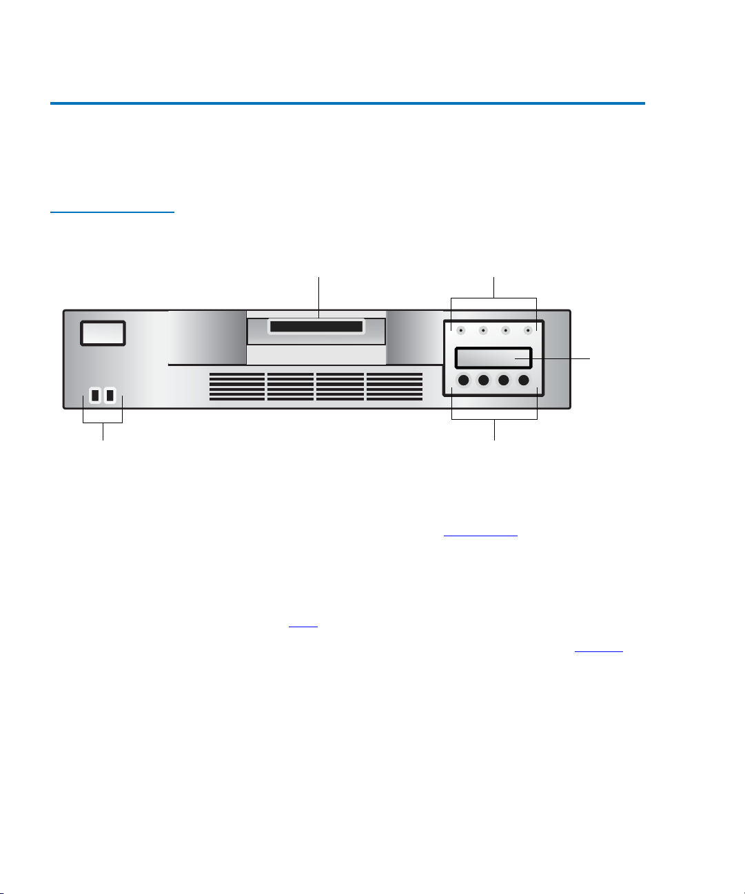
Figure 1 Front Panel
Components
Cartridge access port Status LEDs
Liquid
crystal
display
KeypadPower switch
• Cartridge access port —Used to insert or remove cartridges from the
autoloader.
•
Status LEDs — Consists of several lights that provide information
about various system functions. See Status LEDs
on page 26 for more
information.
•
Liquid crystal display (LCD) — Displays two lines of text with 16
characters per line. The screen displays actions and status
information, menu items, and error messages, based on the operation
mode. See LCD
•
Keypad — Performs various tasks in interaction mode. See Keypad on
on page 27 for more information.
page 27 for more information.
•
Power switch — Lets you turn the autoloader and the enclosed tape
drive off and on. The switch is recessed into the front panel to
prevent the autoloader from being accidentally turned off during
operation.
2 LTO Ultrium 8-Slot Autoloader User’s Guide
Page 19
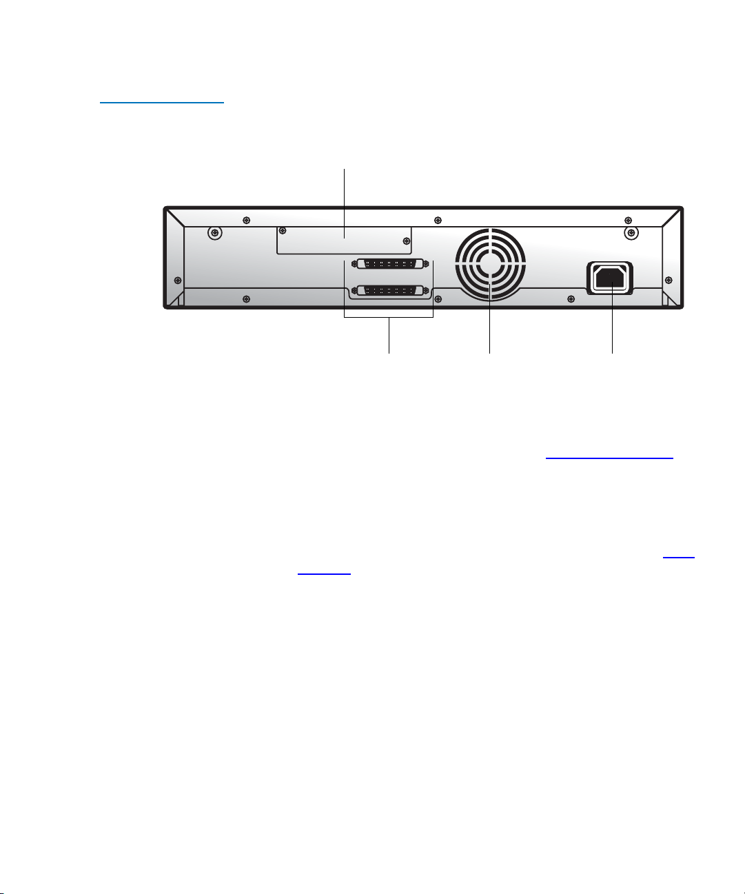
Figure 2 Back Panel
Components
Chapter 1 Quick Start
Autoloader Components
Bar code reader (optional)
SCSI connectors Fan AC outlet
• Bar code reader — The bar code reader is an optional accessory that
automatically scans each cartridge in the carousel. The information
from each bar code label is stored in memory and available through
SCSI to the computer’s operating system or backup application. For
more information on the bar code reader, see Optional Accessories
on
page 12.
•
SCSI connectors — The autoloader has two wide SCSI connectors for
connecting the autoloader and tape drive to a single SCSI bus. The
connectors can accommodate either of the following:
• A shielded male, high-density wide (68-pin) SCSI cable ( see SCSI
Interface on page 46.)
• An LVD or multi-node terminator
The wide SCSI configuration allows up to 16 devices (including one
or more initiators) to be attached to a single SCSI bus.
•
Fan — The system fan provides cooling for the autoloader and the
tape drive.
•
AC outlet — The AC outlet provides AC power and chassis
grounding to the autoloader and the tape drive.
LTO Ultrium 8-Slot Autoloader User’s Guide 3
Page 20
Chapter 1 Quick Start
Autoloader Components
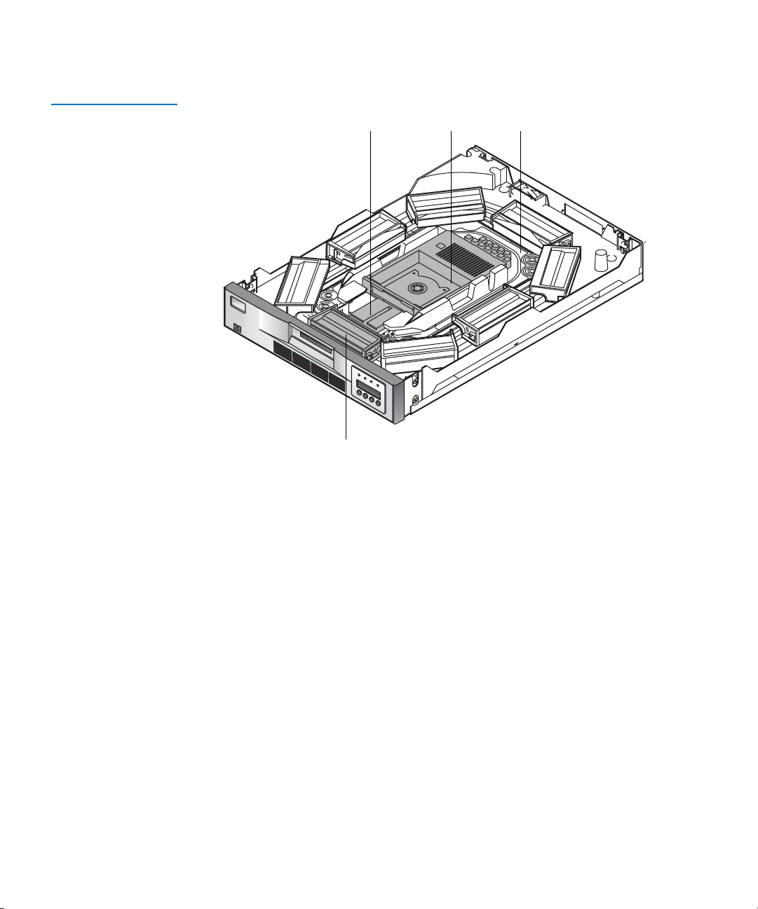
Figure 3 Internal
Components
Cartridge loader Tape drive Carousel
Cartridge slots
• Cartridge loader — The cartridge loader moves cartridges between
the cartridge slots and the tape drive. When a cartridge slot is
positioned in front of the tape drive, the loader grips the sides of the
cartridge and slides it forward or backward, between the slot and
tape drive. The loader then releases the cartridge and pushes it firmly
into the drive or slot.
•
Tap e drive — The autoloader contains one tape drive. Please see the
associated User's Guide for the particular LTO version for details of
tape drive performance and operation.
•
Cartridge slots and carousel — The carousel stores up to eight data
cartridges. The carousel consists of a drive chain, guides, and gears
that move the cartridges into position in front of the tape drive. Each
cartridge is installed in a cartridge slot that ensures that the cartridge
is properly aligned to be inserted into the tape drive. If desired, you
can use one cartridge slot to hold a cleaning cartridge.
4 LTO Ultrium 8-Slot Autoloader User’s Guide
Page 21
Chapter 1 Quick Start
Starting the Autoloader
Starting the Autoloader 1
To start the autoloader:
1 Attach the power cord to the autoloader, and then to the AC outlet.
For more information on power cords, see Power Specifications
page 50.
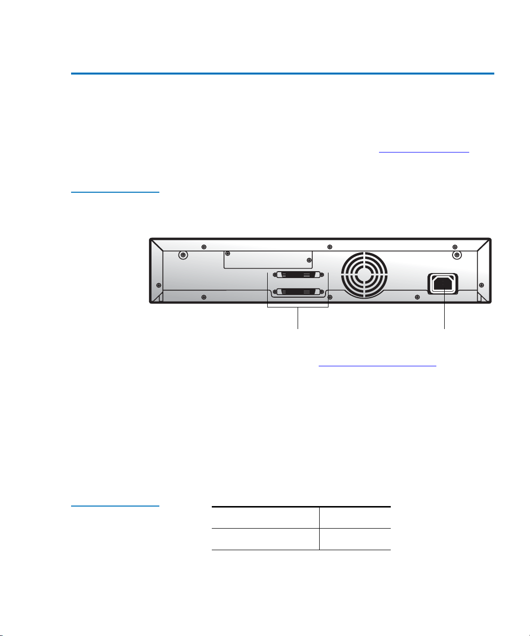
Figure 4 Attaching the
Power Cord and a
SCSI Terminator
on
Table 1 SCSI ID
Default Settings
AC outletSCSI connectors
2 Connect the SCSI cables and the terminator. For more information
about the SCSI interface, see Performance Specifications
on page 49.
• Connect one end of the SCSI cable to one of the SCSI connectors
on the back of the autoloader.
• Connect the other end of the SCSI cable to the SCSI connector on
the SCSI host bus adapter or on the previous device of the SCSI
bus.
• If this is the last device in the SCSI chain, connect the SCSI
terminator to the remaining SCSI connector on the back of the
autoloader.
Autoloader 5
Tape drive 6
LTO Ultrium 8-Slot Autoloader User’s Guide 5
Page 22

Chapter 1 Quick Start
Starting the Autoloader
Figure 5 Pressing the
Power Switch
To change the SCSI ID settings, see Changing the SCSI ID
Settings on page 47.
3 Use the eraser end of a pencil, or something similar, to press the left
side of the power switch. The autoloader powers up. Never use a
metal object, such as a screwdriver.
Note: The power switch lets you turn the power on and off for
the autoloader and the enclosed tape drive. The power
switch is recessed into the front panel to prevent the
autoloader from being accidentally turned off during
operation.
When the autoloader powers up, or resets, it goes through several
internally controlled processes that allow it to get initialized and
running. While those processes are happening, the Operator’s Panel
displays appropriate information to keep you informed about the
events taking place. After initialization, the autoloader displays the
mount status for the current drive. It also indicates that the sequential
mode is ON by displaying the characters SEQ.
In addition, the appropriate inventory status characters display. For
more information about inventory status characters, see Inventory
Status Characters on page 29.
4 Start the host computer system.
6 LTO Ultrium 8-Slot Autoloader User’s Guide
Page 23
Chapter 1 Quick Start
X
-
+
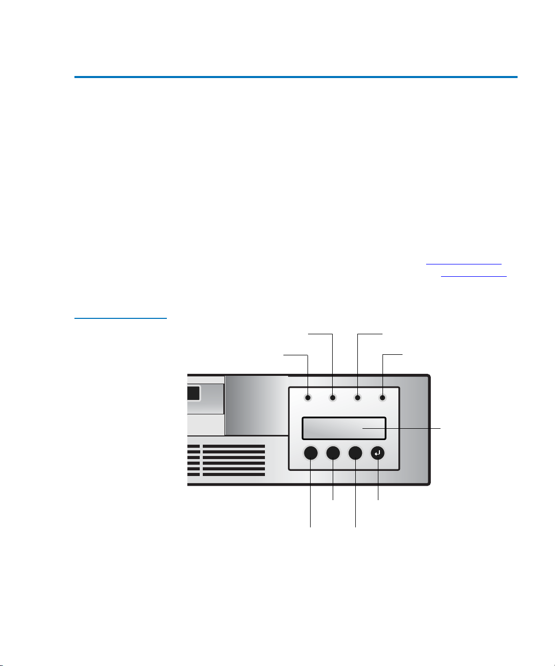
Operator's Panel
Operator's Panel 1
The Operator's Panel consists of various status LEDs, an LCD, and
keypad buttons that enable you to perform various tasks.
The following keypad buttons are used to navigate the menu options:
•
CANCEL button [X] — Cancel a user action and return to the last
menu item.
•
PREVIOUS button [-] — Navigate through menu items.
•
NEXT button [+] — Navigate through menu items.
•
ENTER button [ø] — Go to a sub-menu or to force a robotic action.
Figure 6 Operator’s
Panel
For more information about the Operator’s Panel, see Operator's Panel
page 25. For more information on the menu options, see Menu Options
on page 28.
Clean Drive LED Media Attention LED
Ready/Activity LED
--
XX
++
EnterPrevious
NextCancel
Error LED
LCD
on
LTO Ultrium 8-Slot Autoloader User’s Guide 7
Page 24

Chapter 1 Quick Start
Installing the Data Cartridges
Installing the Data Cartridges 1
Before using the autoloader, the data cartridges must be installed
properly. For more information on data cartridges, see Data Cartridges
on page 22.
Caution: The tape drive only operates with LTO-3 Ultrium (LTO-3
autoloader only), LTO-2 Ultrium (LTO-3 and LTO-2
autoloaders only), or LTO-1 Ultrium tape data cartridges.
Attempting to use other types of cartridges may damage
the unit. For best performance, Certance-brand cartridges
are recommended.
To install the data cartridges:
1 Press any button on the Operator’s Panel to change to
mode.
2 Choose the
3 Choose
4 Enter the number of the cartridge slot and press
5 Insert the cartridge in the cartridge access port. The cartridge is now
placed in the selected slot.
6 Repeat steps 4 and 5 until all cartridges have been imported.
Commands menu, and then press Enter.
Import and press Enter.
Interaction
Enter.
8 LTO Ultrium 8-Slot Autoloader User’s Guide
Page 25

Chapter 2
2Introduction
The autoloader provides automated data storage, archival, backup, and
retrieval for a range of systems, from desktop workstations to small office
local area networks.
This chapter contains general information about the autoloader,
including:
Figure 7 Autoloader
• Features
• Accessories
LTO Ultrium 8-Slot Autoloader User’s Guide 9
.
Page 26

Chapter 2 Introduction
Features
Features 2
The LTO Ultrium 8-Slot Autoloader includes the following features:
• A carousel that encircles the tape drive and positions the specified
cartridge slot in front of the tape drive. A robotic cartridge loader
moves the cartridges between the cartridge slots and the tape drive.
• Storage for up to eight cartridges. Cartridges are stored in cartridge
slots mounted on the carousel. One of these cartridge slots can
contain a cleaning cartridge.
• A cartridge access port for importing or exporting a single cartridge
from the autoloader.
• A liquid crystal display that lets you monitor autoloader operations,
select configuration options, and control the cartridge loader and
carousel from the front panel.
• The autoloader and the tape drive each include independent Small
Computer System Interface (SCSI) controllers. Each supports
independent sets of SCSI messages and commands. The autoloader
and the enclosed tape drive use a wide, low-voltage differential
(LVD) SCSI interface.
Note: The LVD SCSI interface is compatible with single-ended
SCSI.
Table 2 Physical
Characteristics and
Features
Drive technology LTO Ultrium 3 LTO Ultrium 2 LTO Ultrium 1
Total drives 1 1 1
Total storage elements 8 8 8
Cartridge access port 1 1 1
LCD display size and
type
10 LTO Ultrium 8-Slot Autoloader User’s Guide
Two-line x 32
character, ASCII
Two-line x 32
character, ASCII
Two-line x 32
character, ASCII
Page 27

Chapter 2 Introduction
Accessories
LCD user interface Four-button
keypad
Maximum capacity 6.4TB/ 3/2TB
(Compressed/
Native)
Maximum sustained
data transfer rate
MB/Sec
T able 3 Parallel SCSI
Communication
Interface
132/68
(Compressed/
Native)
Low-voltage differential (LVD) + SE YES
Maximum SCSI bus connections 1
Four-button keypad Four-button keypad
3.2TB/1600GB
(Compressed/
Native)
68/32
(Compressed/
Native)
1.6TB/800GB
(Compressed/
Native)
32/16
(Compressed/
Native)
Accessories 2
The autoloader is shipped with the following accessories:
• Power cord and adapter
•One wide SCSI-3 cable
• One LVD wide SCSI terminator (included in some configurations)
• Resource CD (product documentation). Basic diagnostic software for
the tape drive and autoloader is available at www.quantum.com/
support. Please see the online documentation on the CD for details
about installation and operation.
LTO Ultrium 8-Slot Autoloader User’s Guide 11
Page 28

Chapter 2 Introduction
Optional Accessories
Optional Accessories 2
• Rack-mount kit — If you want to mount the autoloader in a rack,
you can purchase a rack-mount kit. The kit includes all the
necessary hardware to mount the autoloader in a standard 19inch EIA rack. The autoloader occupies two rack units.
•
Bar code reader — Your autoloader may have come equipped
with an optional bar code reader. The bar code reader
automatically scans each cartridge in the carousel upon power
up, after a reset, or when the Re-Inventory command is used.
Beyond that, there is no user interface with the bar code reader
via the front panel operator controls or liquid crystal display.
If utilizing the bar code reader, you must apply bar code labels to
the recessed area on the front of each cartridge. The information
from each label is stored in memory and available through SCSI
to the computer's operating system or backup application, upon
request. The labels must conform to ANSI/AIM BC1 -1995,
Uniform Symbology Specification Code 39.
The bar code reader is enclosed in a plastic housing that
protrudes out the rear panel of the autoloader, just above the
SCSI connectors.
12 LTO Ultrium 8-Slot Autoloader User’s Guide
Page 29

Chapter 3
3Setting Up the Autoloader
This chapter describes how to set up the autoloader, and install the
autoloader into a rack, if desired. Setting up the autoloader involves the
following steps:
1 Choosing a Location
2 Unpacking the Autoloader
3 Installation Options
4 Connecting the Cables on page 21.
5 Data Cartridges
.
.
on page 22
Choosing a Location 3
Choose a location that meets the following criteria (see Specifications on
page 45 for more information on autoloader specifications):
LTO Ultrium 8-Slot Autoloader User’s Guide 13
Page 30

Chapter 3 Setting Up the Autoloader
Choosing a Location
• Select a location that is flat, sturdy, level, and close to a host server.
Do not place the autoloader on the floor or other carpeted surfaces.
Caution: Do not place the autoloader on its side or upside
• Rack requirements — Standard 19-inch rack with 2U of clearance
• Room temperature —
• LTO Ultrium 2 and LTO Ultrium 1: 50-95º F (10-35º C)
• LTO Ultrium 3: 50-104º F (10-40º C)
•Power source —
• AC power voltage: 100-127 VAC
• 200-240 VAC line frequency: 50-60 Hz
Note: Locate the AC outlet at the back of the autoloader. The
down, or stack items that weigh more than 33 lbs.
(15 kg) on top of the autoloader.
power cord is the autoloader's main AC disconnect device
and must be easily accessible at all times.
• Weight — 19.5 lbs. (8.8 kg)
• Air quality — Minimal sources of particulate contamination. Avoid
areas near frequently used doors and walkways, stacks of supplies
that collect dust, printers, and smoke-filled rooms.
Caution: Excessive dust and debris can damage tapes and tape
drives.
• Humidity — 20-80% RH non-condensing
• Clearance —
• Back (minimum of six inches [15.4 cm])
• Front (minimum of 12 inches [30.8 cm])
• Sides (minimum of two inches [5.08cm])
14 LTO Ultrium 8-Slot Autoloader User’s Guide
Page 31

Chapter 3 Setting Up the Autoloader
Unpacking the Autoloader
Checking the Installation Environment
After choosing a location for the autoloader, consider the following:
• The maximum recommended ambient temperature for the
3
autoloader is
in an environment compatible with this temperature.
• The fan opening at the rear of the autoloader and the vent openings
in the front should be free of cables and other obstructions.
• Make sure the supply circuit is suitable for all equipment loads in the
rack.
• Make sure the outlet or power strip that you intend to use is reliably
grounded.
• Make sure that the installation environment is free of conditions that
could cause electrostatic discharge (ESD). If possible, use an antistatic
mat and grounded static protection wristband during installation. If a
mat and wristband are not available, touch a known grounded
surface, such as a computer’s metal chassis.
+50°F to +104 °F (+10 °C to +40 °C). Install the autoloader
Unpacking the Autoloader 3
No special tools are required for unpacking the autoloader. Save all the
original packing materials, including the accessory box, in case you need
to ship or move the autoloader at a later time.
Installation Options 3
You have the option of installing the autoloader into a rack, or using it as
a standalone unit.
• If you are installing the autoloader into a rack, go to Installing the
Autoloader into a Rack.
• If you are using the autoloader as a standalone unit, go to Connecting
the Cables on page 21.
LTO Ultrium 8-Slot Autoloader User’s Guide 15
Page 32

Chapter 3 Setting Up the Autoloader
Installing the Autoloader into a Rack
Installing the Autoloader into a Rack 3
The autoloader can be installed into a standard 19-inch rack.
Requirements 3
To install the autoloader into a rack, you will need the following:
• #2 PHILLIPS® screwdriver
• TORX T-10 screwdriver
• Rack mount kit — Make sure the rack-mount kit contains the
following items:
• Two support rails
• Two rack-mount brackets
•Ten screws
•Ten clip-nuts
16 LTO Ultrium 8-Slot Autoloader User’s Guide
Page 33

Figure 8 Rack Mount
Kit
Chapter 3 Setting Up the Autoloader
Installing the Autoloader into a Rack
Screw
Support rails
Preparing the Autoloader
Rack-mount brackets
If the autoloader is currently in operation as a standalone unit, prepare it
for installation in the rack as follows:
3
Warning: Before performing any installation or maintenance
procedures, be sure that the power switch is off and that
the power cord is disconnected from the autoloader and
the AC outlet.
1 Power off the autoloader by pressing the right side of the recessed
power switch located on the autoloader’s front panel. Use the eraser
end of a pencil or a similar object to press the power switch.
Note: To avoid disrupting communication between the host
computer and other devices on the SCSI bus, make sure
that there is no SCSI activity on the bus before you power
off the autoloader.
Clip-nut
LTO Ultrium 8-Slot Autoloader User’s Guide 17
Page 34

Chapter 3 Setting Up the Autoloader
Installing the Autoloader into a Rack
Figure 9 Power
Switch
2 Remove the power cord and any SCSI cables or terminators attached
to the autoloader. Note the configuration of the cables and
terminator. You will need to reinstall them after installing the
autoloader in the rack.
Installing the Support Rails
To install the support rails in the rack:
3
1 Remove the two support rails from the kit and note how they will be
positioned in the rack. When the rails are installed, the shelf flanges
will face inward to support the autoloader.
2 From the front of the rack, position one of the rails on the appropriate
side. Slide the rail pieces apart to match the depth of your rack.
Position the front flange so that it is on the outside of the strip of
mounting holes in the rack.
3 Using a #2 Phillips screwdriver, attach the rail to the rack with four of
the screws from the kit. If your rack has square mounting holes, or
the holes are larger than the screws provided in the kit, use the clipnuts to secure the screws, as shown in the following figure.
18 LTO Ultrium 8-Slot Autoloader User’s Guide
Page 35

Figure 10 Attaching
the Rails to the Rack
Chapter 3 Setting Up the Autoloader
Installing the Autoloader into a Rack
Clip-nut
Front flange
Front flange
Installing the Rack-Mount Brackets
4 Repeat steps 2 and 3 for the second rail.
To install the rack-mount brackets on the autoloader:
1 Remove the rack-mount brackets from the rack-mount kit and
3
determine on which side of the autoloader you will attach them, as
follows:
• From the front of the rack, slide the autoloader partially onto the
shelf flanges between the support rails you just installed.
• Holding one of the rack-mount brackets against one side of the
autoloader, line up the two holes in the bracket with the two
screw holes on the side of the autoloader. The flange on the
bracket should be toward the front of the autoloader, facing
outward.
LTO Ultrium 8-Slot Autoloader User’s Guide 19
Page 36

Chapter 3 Setting Up the Autoloader
Installing the Autoloader into a Rack
• Slide the autoloader into the rack until the bracket you are
• Determine whether the screw hole on the bracket flange lines up
2 Remove the autoloader from the shelf and place it on the work
surface.
3 Using a TORX T-10 screwdriver, remove the two screws on each side
of the autoloader.
4 Position the correct bracket, as determined in step 1, on each side of
the autoloader. Secure each bracket by replacing the original screws.
Figure 11 Securing
the Brackets
Flange
Rack-mount bracket
holding contacts the rack’s mounting holes.
with a mounting hole in the rack. If it does, you will mount the
bracket on that side of the autoloader. If not, you will mount it on
the other side of the autoloader.
Securing the Autoloader
To secure the autoloader to the rack:
3
1 From the front of the rack, position the autoloader on the shelf
flanges between the support rails. Slide it toward the rear of the rack
until the brackets contact the rack’s mounting holes. Make sure that
the tabs on the back of each shelf flange are fully engaged in the slots
at the rear of the autoloader.
20 LTO Ultrium 8-Slot Autoloader User’s Guide
P
O
W
E
R
M
E
N
U
-
+SE
LE
C
T
Page 37

Figure 12 Securing
the Autoloader to the
Rack
Chapter 3 Setting Up the Autoloader
Connecting the Cables
2 Place one screw from the rack-mount kit into the hole in the front of
each bracket. If your rack has square mounting holes or the holes are
larger than the screws provided in the kit, use the clip-nuts to secure
the screws. Use a #2 PHILLIPS screwdriver to tighten the screws.
P
O
W
E
R
M
E
N
U
-
+
S
E
L
E
C
T
Connecting the Cables 3
To connect the cables to the autoloader:
1 Make sure that the power switch on the front of the autoloader is off
(the right side of the power switch is pressed).
2 Connect the female end of the power cord to the AC outlet on the
back of the autoloader.
Note: The power cord shipped with the autoloader is a 120 VAC
three-conductor power cord for use in the United States
and Canada. An adapter for use outside of the United
States and Canada is also included.
LTO Ultrium 8-Slot Autoloader User’s Guide 21
Page 38

Chapter 3 Setting Up the Autoloader
Data Cartridges
3 Connect the male end of the power cord to the power outlet.
4 Connect the SCSI cables and the terminator. For more information
about the SCSI interface, see SCSI Interface
• Connect one end of the SCSI cable to one of the SCSI connectors
• Connect the other end of the SCSI cable to the SCSI connector on
• If this is the last device in the SCSI chain, connect the SCSI
5 Push the power switch on the front of the autoloader to the ON
position (press the left side of the switch).
6 Power on the host computer system.
on page 46.
on the back of the autoloader.
the SCSI host bus adapter or on the previous device of the SCSI
bus.
terminator to the remaining SCSI connector on the back of the
autoloader.
Data Cartridges 3
Installing the Data Cartridges
22 LTO Ultrium 8-Slot Autoloader User’s Guide
3
Caution: The tape drive only operates with LTO-3 Ultrium (LTO-3
autoloader only), LTO-2 Ultrium (LTO-3 and LTO-2
autoloaders only), or LTO-1 Ultrium tape data cartridges.
Attempting to use other types of cartridges may damage
the unit. For best performance, Certance-brand cartridges
are recommended.
Note: Do not open the front door of the autoloader unless you must
perform interaction mode commands or change media. Use
only the recommended types of media cartridges. Clean the
drive whenever necessary.
Caution: Never insert or remove cartridges from the cartridge slot
unless READY/ACTIVITY is lit.
Page 39

Chapter 3 Setting Up the Autoloader
Data Cartridges
To install the data cartridges:
1 Press any button on the Operator’s Panel to change to interaction
mode.
2 Choose the
3 Choose
4 Enter the number of the cartridge slot and press
Commands menu, and then press Enter.
Import and press Enter.
Enter.
5 Insert the cartridge in the cartridge access port. The cartridge is now
placed in the selected slot.
6 Repeat steps 4 and 5 until all cartridges have been imported.
The
Import command in the Library Commands menu places a cartridge
into a specific cartridge slot through the cartridge access port. When you
use the
Import command, the cartridge carousel moves the specified
cartridge slot into position in front of the cartridge access port and slides
the door open. You can then push the cartridge into the slot through the
door. The cartridge loader then grasps the cartridge, pulls it into the
autoloader, and closes the door.
The
Export command lets you remove a cartridge from a specific
cartridge slot through the cartridge access port. When you use the
Export
command, the cartridge carousel moves the specified cartridge slot into
position in front of the cartridge access port and slides the door open. The
cartridge loader then pushes the cartridge far enough out through the
door to allow you to remove it.
Loading and Unloading a Cartridge
The Load Cartridge command in the Commands menu lets you load the
cartridge in the specified slot into the tape drive. When you use the
Cartridge
3
command, the cartridge carousel moves the specified cartridge
slot into position in front of the tape drive. The cartridge loader then
extracts the cartridge from the cartridge slot and inserts it into the tape
drive.
The
Unload Cartridge command causes the tape drive to unload the tape
from the tape path and eject the cartridge. After the cartridge is ejected,
the cartridge carousel moves the slot from which the cartridge originated
into position in front of the tape drive. The cartridge loader then extracts
the cartridge from the tape drive and returns it to the cartridge slot.
LTO Ultrium 8-Slot Autoloader User’s Guide 23
Load
Page 40

Chapter 3 Setting Up the Autoloader
Data Cartridges
Updating the Cartridge Inventory
After you import or export a data cartridge, you can update the cartridge
inventory using the
menu. The autoloader checks for the presence of a cartridge in each
3
Re-inventory Option command in the Commands
cartridge slot.
24 LTO Ultrium 8-Slot Autoloader User’s Guide
Page 41

Chapter 4
4Operating the Autoloader
This chapter information about using the autoloader, including:
• Operator's Panel
• Menu Options
• Inventory Status Characters
• Operating Modes
• Autoloader Operations
• Maintenance
• Shipping the Autoloader
on 25
on 28
on 29
on 30
on 32
on 34
on 35
Operator's Panel 4
The operator's panel consists of the following:
• Status LEDs
• LCD
• Keypad
on 27
on 26
on 27
LTO Ultrium 8-Slot Autoloader User’s Guide 25
Page 42

Chapter 4 Operating the Autoloader
X
-
+
Operator's Panel
Figure 13 Operator’s
Clean Drive LED Media Attention LED
Panel
Ready/Activity LED
--
XX
++
EnterPrevious
NextCancel
Error LED
Liquid crystal display
Status LEDs 4 The LEDs are updated during power up and reset sequences. Upon
power up or software reset, the autoloader will illuminate all LEDs as
soon as the power-on self-test (POST) allows. This assists you in verifying
that all LEDs are functional.
When mechanical initialization starts, all LEDs will be extinguished and
the
READY/ACTIVITY LED will flash at a reasonable rate of approximately
one second per cycle.
When the mechanical initialization is complete, the
will stop flashing and be constantly illuminated.
If a loader failure occurs, the
the
ERROR LED will be illuminated. The Operation’s Panel will also
READY/ACTIVITY LED will be turned off and
display an appropriate error code to help identify the failure.
Note: The circuitry to illuminate four external LED's is incorporated
into the autoloader.
•
READY/ACTIVITY (Green LED) — Lit any time the unit is powered on
and able to function. It should blink whenever there is autoloader or
drive activity.
26 LTO Ultrium 8-Slot Autoloader User’s Guide
READY/ACTIVITY LED
Page 43

Chapter 4 Operating the Autoloader
Operator's Panel
• CLEAN DRIVE (Amber LED) — Lit when the drive is to be cleaned.
The LED will be turned off after the drive is cleaned successfully.
•
MEDIA ATTENTION (Amber LED) — Lit when there has been a failure
that indicates that there is a piece of media that is bad, marginal, or
invalid. It will be cleared when all invalid cartridges have been
exported from the autoloader.
•
ERROR (Red LED) — Lit when there is an unrecoverable autoloader
or drive failure. A message displays at the same time on the screen. It
will be cleared when the error state is resolved.
LCD 4 The LCD consists of two lines, with 16 characters per line. The screen
displays actions, status information, menu items, and error messages
equivalent to the operation mode.
Keypad 4 The keypad buttons are used for navigating the various menu options
that are available. For more information on the menu options, see Menu
Options on 28.
Note: The keypad buttons are only available for use in interaction
mode. For more information on operating modes, see
Operating Modes
•
CANCEL button [X] — Push the Cancel button to cancel a user action
on 30.
and return to the last menu item.
•
PREVIOUS button [-] — Navigate through menu items.
•
NEXT button [+] — Navigate through menu items.
•
ENTER button [ø] — Push the Enter button to go to a sub-menu or to
force a robotic action.
LTO Ultrium 8-Slot Autoloader User’s Guide 27
Page 44

Chapter 4 Operating the Autoloader
Menu Options
Menu Options 4
Figure 14 Autoloader
Menu Options
Commands Information Configuration Diagnostic
Import
Export
Load cartridge
Unload
cartridge
Clean drive
Re-Inventory
Cycle count
View event log
Product Rev.
Serial numbers
Firmw are
revisions
Reset
Change SCSI
ID
Code update
Circular mode
Autoload mode
System test
The menu options are accessed from the Operator’s Panel by pressing the
Enter button. Use the Previous and Next buttons to navigate through the
menu items. Use the
Cancel button to cancel the last action and return to
the previous menu item.
For most installations, the default configuration for the autoloader does
not need to be changed. However, if necessary, you can use the
Operator’s Panel to change the SCSI IDs for the autoloader and the tape
drive using the
Configuration menu.
Note: The autoloader and the tape drive must each have unique SCSI
IDs. It is your responsibility to make sure you do not assign
duplicate IDs within a bus. For more information on changing
SCSI IDs, see SCSI ID Settings
28 LTO Ultrium 8-Slot Autoloader User’s Guide
on page 47.
Page 45

Chapter 4 Operating the Autoloader
Inventory Status Characters
Inventory Status Characters 4
The inventory status characters represent the status of each slot within
the tape drive. They display in the second line of text in the liquid crystal
display as an eight-character string, with four blank spaces on each side.
Table 4 Inventory
Status Characters
Character Meaning
1 … 8
-
Slot Full: Indicates that slot contains a cartridge
Slot Empty: Indicates the slot does not contain a
cartridge.
1/J A cartridge that is being loaded, unloaded, imported,
exported, or is loaded in the drive is represented by the
slot number alternating with the block (J) character.
! (Exclamation point and the
Media Attention LED is on)
The cartridge in that slot is faulty. An invalid cartridge
is identified the same way.
To clear the faulty status (exclamation point) and the Media Attention
LED, export the faulty cartridge.
If a drive does not contain any cartridges, the following displays in the
liquid crystal display. In this example, there is no cartridge in slot 6.
Drive empty
12345-78 SEQ
If the autoloader detects that a cartridge is loaded when it first powers on,
the following displays in the liquid crystal display. In this example, there
is no cartridge in slot 6. If the cartridge in the drive came from slot 8, the 8
would be alternating with the block character.
LTO Ultrium 8-Slot Autoloader User’s Guide 29
Page 46

Chapter 4 Operating the Autoloader
Operating Modes
Drive loaded
12345-78 SEQ
Operating Modes 4
The System Driven mode is the normal mode of operation. In this mode,
the Operator’s Panel displays the status associated with the actions that
were caused from commands issued via the drive's SCSI interface. Some
of these actions including loading, rewinding, and moving tape display.
When an operator’s panel button is pressed and released, the operator’s
panel changes to
the unit.
Interaction mode. In Interaction mode, you can operate
Interaction mode continues for three minutes after you stop pushing
buttons or the requested robotic action stops. After this time, the
operator’s panel returns to
The autoloader has two operating modes —
System Driven mode automatically.
Random and Sequential. The
operating mode used depends on whether automation software is
controlling cartridges in the autoloader. Initially, the autoloader assumes
you are not using automation software to control cartridge or drive
activity. This is called
Sequential mode. If the autoloader detects that
automation software is controlling tape drive activity, it switches to
Random mode automatically.
Note:
SEQ appears in the operator's panel LCD when the autoloader
is in
Sequential Mode. No message appears during Random
Mode.
The following sections provide more information about
Random modes.
Sequential and
30 LTO Ultrium 8-Slot Autoloader User’s Guide
Page 47

Chapter 4 Operating the Autoloader
Operating Modes
Random Mode 4 Random mode is the normal operating mode when a backup software
application is being used. In
Random mode, the autoloader loads tape
into the drive when it receives the appropriate commands from software.
To use this mode, your backup software must support autoloaders. This
support often requires an autoloader/library software module to be
installed.
Sequential Mode 4 Sequential mode is used when autoloader software is not available. In
Sequential mode, the autoloader loads and unloads tapes automatically.
The operator specifies which tape is to be loaded first by using the
autoloader operator's panel controls. (For more information on loading
cartridges, see Loading and Unloading a Cartridge
on page 23.)
When the first tape is full or unloaded, the autoloader removes the tape
from the drive automatically, returns it to its original slot, and loads
another tape in the next higher numbered slot that is available. For
additional control over loading tapes in
Circular and Autoload options from the autoloader’s front panel.
Sequential mode, you can set
Circular Mode
This option is accessed from the Configuration menu. When Circular mode
is enabled, the autoloader reloads the original first cartridge in the
sequence after it cycles through all available cartridges. If
Circular mode
is disabled, the autoloader stops loading cartridges after the last cartridge
has been unloaded and waits until you load another cartridge manually.
Caution: Use caution with circular mode, as it can overwrite data on
previously written cartridges.
Autoload Mode
This option is accessed from the Configuration menu. When autoload
mode is enabled, the autoloader automatically loads the cartridge from
the lowest numbered full slot into the tape drive when powered on. It
then follows standard sequential operation as described above.
LTO Ultrium 8-Slot Autoloader User’s Guide 31
4
4
Page 48

Chapter 4 Operating the Autoloader
Autoloader Operations
Write-Protected Media
If the drive detects a write-protected media, an internal bit is set and the
autoloader posts the 'WP' string on the display indicating a write
4
protected media is loaded in the drive. The display shows the following
status:
As soon as the write-protected media is ejected, the drive resets the
internal bit and the 'WP' string on the display is cancelled.
Autoloader Operations 4
After you install and configure the autoloader and install your
application software on the host computer, the autoloader performs most
operations automatically. Operator intervention includes the following
activities:
• Monitoring autoloader operation and status
• Performing autoloader and tape drive operations
Monitoring the Autoloader Operation and Status
32 LTO Ultrium 8-Slot Autoloader User’s Guide
During normal operation, the Status screen is displayed on the liquid
crystal display. You can use this screen to monitor autoloader activities.
By default, the
autoloader and tape drive.
4
To set the Operator’s Panel to
lets you use the keypad to display options for issuing commands to the
autoloader, viewing information screens, and configuring the autoloader.
Status screen displays the current operating status of the
Interaction mode, press any key. This mode
Page 49

Chapter 4 Operating the Autoloader
Autoloader Operations
Performing Autoloader and Tape Drive Operations
Resetting the Autoloader
Resetting the T ape Drive
The Commands menu provides options for importing and exporting
cartridges, loading and unloading a cartridge from the tape drive,
cleaning the tape drive, and updating the cartridge inventory. For more
information on data cartridges, see Data Cartridges
4
on page 22.
A reset causes the autoloader to perform its power-on self-test (POST)
and check for the presence of the data cartridges. The autoloader can be
4
reset in any of the following ways:
• Power-on reset — Powering the autoloader off (or unplugging it),
and then back on again, resets the autoloader and the tape drive.
• Operator’s Panel — Choose the
choose
Reset, and then press Enter. For more information about using
the Operator’s Panel, see Operator's Panel
Configuration menu, press Enter,
on page 7.
• Bus device reset message — Issuing a bus device reset message from
the SCSI application program can reset either the autoloader or the
tape drive.
Resetting the tape drive does not cause a cartridge loaded in the drive to
be ejected. If a cartridge is in the tape drive during a reset, make sure that
4
it is safe to overwrite the loaded cartridge before performing a backup. If
you perform a backup without checking the loaded cartridge, you may
lose important data from a previous backup.
LTO Ultrium 8-Slot Autoloader User’s Guide 33
Page 50

Chapter 4 Operating the Autoloader
Maintenance
Maintenance 4
The autoloader requires no routine maintenance. Parts can be serviced
only by the manufacturer, an approved maintenance organization, or by
self-maintenance contract customers.
Caution: Do not clean or lubricate any of the autoloader’s
mechanical assemblies. Lubricating may adversely affect
the function of those parts. All other parts can be serviced
only by the manufacturer, an approved maintenance
organization, or by self-maintenance contract customers.
Note: The autoloader warranty does not apply to failures of the
autoloader when it is repaired by untrained or unauthorized
service personnel.
Cleaning the Tape Drive
34 LTO Ultrium 8-Slot Autoloader User’s Guide
The tape drive requires regular cleaning with an LTO tape cleaning
cartridge to maintain optimal performance. Following a regular cleaning
4
schedule for your tape drive will maximize the reliability of your drive
and the life of your LTO tape data cartridges.
Caution: Do not use cleaning cartridges other than a Quantum-
approved LTO cleaning cartridge. Carefully follow all
instructions and recommendations provided with the
cleaning cartridge.
Note: The tape drive can also report its cleaning requirements to the
application software. Your application may notify you when
the tape drive needs cleaning. Refer to your application
documentation for more information.
To clean the tape drive, make sure there is an empty slot available to hold
the cleaning cartridge. Select the
menu on the Operator’s Panel. When you use this option, the autoloader
imports a cleaning cartridge through the cartridge access port and inserts
it into the tape drive. When the cleaning is complete, the tape drive ejects
Clean drive option from the Commands
Page 51

Chapter 4 Operating the Autoloader
Shipping the Autoloader
the cleaning cartridge and the autoloader returns it to the cartridge access
port for removal.
Alternatively, you can store a cleaning cartridge in one of the cartridge
slots. You use the
slot containing the cleaning cartridge into position and load the cartridge
into the tape drive. When the cleaning is complete, the tape drive ejects
the cleaning cartridge and the autoloader returns it to the slot from which
it originated. Although this alternative lets you always have the cleaning
cartridge in the autoloader, it has following disadvantages:
• You have to remember which slot your cleaning cartridge is in.
• The autoloader's data storage capacity is reduced by one cartridge.
Some software applications may support reserving a slot for a cleaning
cartridge and thereby automate the cleaning process. Refer to your
software documentation if your software has this capability.
Load command from the Commands menu to move the
Shipping the Autoloader 4
If you need to ship the autoloader, use the original shipping carton and
packing materials (or replacement packaging obtained from the vendor)
to prevent damage. The shipping carton and packing materials are not
intended to be used for shipping items other than or in addition to the
autoloader.
LTO Ultrium 8-Slot Autoloader User’s Guide 35
Page 52

Chapter 4 Operating the Autoloader
Shipping the Autoloader
36 LTO Ultrium 8-Slot Autoloader User’s Guide
Page 53

Chapter 5
5Troubleshooting and
Diagnostics
The autoloader includes features to support troubleshooting and
diagnostic operations. If an autoloader error occurs, an error message and
error code are displayed on the Operator’s Panel.
Additional diagnostic tests are included on the diagnostic software on the
Resource CD.
Performing a System Test 5
The System Test option cycles the autoloader through the process of
loading, calibrating, and unloading all cartridges in the carousel.
Running a system test verifies the basic operational soundness of the
autoloader and tape drive. The system test continues indefinitely until
you press the Cancel button. All regular backup or restore operations are
suspended while a system test is in progress.
To run a system test:
1 From the main menu, press the Next [+] or Previous [-] button until
Diagnostics appears on the top line of the LCD screen.
2 Press the Enter button.
LTO Ultrium 8-Slot Autoloader User’s Guide 37
System Test is displayed.
Page 54

Chapter 5 Troubleshooting and Diagnostics
Error Codes
3 Press Enter to begin the test. The Test Count displays the number of
load-calibrate-unload cycles that have been completed during the
test.
4 Press the
Cancel button to end the test.
Error Codes 5
T able 5 Oviewview of
Error Codes
Table 6 Robotic
Control Errors
Error Code Hex Notation Error Belonging to
80 - 8F Robotic control errors
90 - 96 Function errors
A0 - A5 Low level axis errors
B0 - B7 Electronic hardware errors
BA - BF Drive errors
Error Code Hex Notation Description
80 No error.
81 Invalid command error. This error
indicates that the Loader received an
undefined command or an invalid
parameter to a command.
82 Device status not suitable to execute this
command. If the robotics are busy, some
commands can't be executed at the same
time. This error will indicate a probable
violation. This is not an error condition,
but does result in busy being reported to
the host for the requested SCSI
command.
38 LTO Ultrium 8-Slot Autoloader User’s Guide
Page 55

Chapter 5 Troubleshooting and Diagnostics
Error Code Hex Notation Description
83 Inventory not valid. The cartridge
inventory is not valid, because of
manual changes or previous fatal errors.
In such case, the inventory must be
updated by appropriate
commands.
84 Source element not ready. The transport
source element is empty.
85 Destination element not ready. The
destination element is already full.
86 Access door not possible. An attempt to
access the door is rejected, while a media
removal is prevented.
87 Timeout. A timeout condition occurred.
Error Codes
Set Slot Status
Table 7 Function
Errors
88 Communications error during loop-
back.
89 Timeout detected by loader on BHC
testing.
8F No error after autoloader recovery.
Error Code Hex Notation Description
90 Mechanical initialization failure. The
robotic wasn't able to get into its safe
mechanical init position. Manual
intervention will be necessary.
91 Scan failure. Fatal error during cartridge
scan, building up inventory.
92 Preposition failed. Belt positioning error
during the
Preposition command.
LTO Ultrium 8-Slot Autoloader User’s Guide 39
Page 56

Chapter 5 Troubleshooting and Diagnostics
Error Codes
Error Code Hex Notation Description
Table 8 Low Level
Axis Errors
Error Code Hex Notation Description
A0 Belt axis error. Error during cartridge
93 Cartridge mount error. Movement of
cartridge into drive failed.
94 Cartridge dismount error. Failure during
cartridge removal and transport back to
the slot.
95 Import error. Device wasn't able to finish
import of new cartridge without error.
96 Export error. Fatal error during cartridge
export.
carrier movement (position not found).
A1 Slider axis error. Transport slider unable
to reach estimated position.
A2 Gripper position error. Gripper unable to
reach position.
A3 Cartridge pick error. Missing cartridge
during pick operation of gripper.
A4 Door function error. Slider door in front
bezel not in requested position during
device operation.
A5 Fan error. Loader processor has detected
a fan error.
40 LTO Ultrium 8-Slot Autoloader User’s Guide
Page 57

Chapter 5 Troubleshooting and Diagnostics
Error Codes
Table 9 Electronic
Harware Errors
T able 10 Drive Errors
Error Code Hex Notation Description
B0 ROM error.
B1 RAM error.
B2 NVRAM error.
B3 CTC error.
B4 UART error.
B5 Display error.
B6 Memory error.
B7 Timeout on loader command.
Error-Code Hex Notation Description
BA Drive load timeout.
BB Drive unload timeout.
Error and Event Log
BC Over temperature problem.
BD No connection to drive.
BE Generic drive response error.
BF Drive broken, needs repair.
Every autoloader provides an internal error and event log with 64 entries.
This log data is helpful for development and service purposes. The error
5
and event log is accessible through the Operator’s Panel and can be read
out entry by entry.
LTO Ultrium 8-Slot Autoloader User’s Guide 41
Page 58

Chapter 5 Troubleshooting and Diagnostics
Error Codes
Log Entry 5 A negative number in the top line shows the current position in the error
log.
Every log entry consists of a type identifier and two data bytes. This
information is shown on the bottom line of the screen.
Entry: AA BB CC AA type identifier
BB data type 1
CC data byte 2
Table 11 Example of
Error/Evemt Log
Display
EVENT -6
03 A0 00
• Sequence number -6 indicates the position in sequence list, 0 being
the most recent.
• Log shows a belt axis error (type identifier: 03 = error, data byte 1: A0
= belt axis error, data byte 2: 00 is not used).
The following entry modes can be assigned by the type identifier:
Table 12 Entry
Modes
Type Description
01 Internal robotic command message which is received by
RobCtrl Module. Data byte 1 will show the command, data
byte 2 means its first parameter (usually cartridge number).
02 Internal robotic command message which is received by
RobTest Module. Data byte 1 will show the command, data
byte 2 means its first parameter (usually cartridge number).
03 Indicates an error message. Errors are represented by the
same codes as described before in this interface specification.
Data byte 2 is not used in this mode.
42 LTO Ultrium 8-Slot Autoloader User’s Guide
Page 59

Chapter 5 Troubleshooting and Diagnostics
Error Codes
Type Description
04 Represents a motion script information. Data byte 1 points to
the current script number, data byte 2 points to the last line
executed in the script. The provided information is rather
extensive and needs to be verified by the developer of the
particular script.
05 Indicates a debug output. This type can be used by a software
developer to fix special problems. Data byte 1 and data byte 2
are free for any usage and may depend on the investigated
problem. This type will only be used during the development
phase.
LTO Ultrium 8-Slot Autoloader User’s Guide 43
Page 60

Chapter 5 Troubleshooting and Diagnostics
Error Codes
44 LTO Ultrium 8-Slot Autoloader User’s Guide
Page 61

Appendix A
ASpecifications
This chapter provides technical specifications for the LTO Ultrium 8-Slot
Autoloader.
The topics covered in this chapter are:
• Size and Weight
• SCSI Interface
• Performance Specifications
• Power Specifications
• Environmental Specifications
• Acoustic Noise Limits
• Shock and Vibration
• Disposal of Electrical and Electronic Equipment
LTO Ultrium 8-Slot Autoloader User’s Guide 45
Page 62

Appendix A Specifications
Size and Weight
Size and Weight 1
Length
Width 16.9 inches (42.9 cm)
Height 3.3 inches (8.4 cm)
Weight 19.5 pounds (8.8 kg) without cartridges installed
24.0 inches (60.9 cm)
SCSI Interface 1
The autoloader has a standard LVD SCSI interface. One SCSI cable and
one SCSI terminator are included with the autoloader. Additional cables
and terminators can be ordered from the manufacturer.
The LVD SCSI interface is compatible with a single-ended SCSI bus.
• Do not attach the autoloader to a non-LVD SCSI controller, as this
will degrade the performance of the tape drive and the performance
of your backups.
• Do not attach non-LVD SCSI devices to the same bus cable as your
autoloader, as this will degrade the performance of the tape drive
and the performance of your backups.
• Do not connect the tape drive to a disk RAID controller, as this is not
supported.
• If you are installing an adapter, it is recommended that you purchase
a SCSI LVD controller kit that includes a SCSI cable and SCSI
terminator (unless provided with your autoloader).
• It is strongly recommended that the autoloader not be attached to the
same SCSI bus as your SCSI hard drive(s).
46 LTO Ultrium 8-Slot Autoloader User’s Guide
Page 63

Appendix A Specifications
SCSI Interface
SCSI ID Settings 1 The autoloader contains two SCSI ID settings — one for the autoloader’s
SCSI controller and one for the tape drive. If there is another device
already assigned to these IDs, you will need to change the IDs. For
information on how to do this, see Changing the SCSI ID Settings
.
Table 13 SCSI ID
Default Settlings
Changing the SCSI ID Settings
Autoloader 5
Tape drive 6
To change the SCSI ID settings:
1
1 From the main menu, press the
Configuration displays in the liquid crystal display.
2 Press
3 Press the
Enter to select the Configuration menu.
Previous or Next button until Change SCSI ID displays in the
LCD
4 Press
5 Press the
Enter to select the Change SCSI ID option.
Previous or Next button until Loader displays in the LCD. To
change the SCSI ID of the tape drive, press the
button until
6 Press
7 Press the
8 Press the
Drive displays in the liquid crystal display.
Enter to select the Loader option.
Previous or Next button until the desired SCSI ID displays.
Enter button. Cycle Power for New SCSI ID displays on the
LCD screen.
Previous or Next button until
Previous or Next
9 Turn off the autoloader. Wait a few seconds, and then turn the
autoloader on again. The selected SCSI ID is now set.
Note: If you change the SCSI ID, you may also need to cycle power
on the host server and reconfigure your backup software
before you can use the autoloader. The autoloader and the
tape drive must each have unique SCSI IDs. It is your
responsibility to make sure you do not assign duplicate IDs
within a bus.
LTO Ultrium 8-Slot Autoloader User’s Guide 47
Page 64

Appendix A Specifications
SCSI Interface
SCSI Cable Requirements
The manufacturer recommends using 68-pin SCSI cables that conform to
SCSI-3 specifications.
1
Caution: All wide SCSI configurations (single-ended, LVD, and
HVD) use the same 68-pin connector. Attaching the
autoloader directly to an HVD SCSI will make the entire
bus non-functional and may permanently damage the
drive or other SCSI devices on the bus.
Note: To comply with the safety and regulatory agency standards for
the autoloader, all SCSI cables you use with the autoloader
must be properly shielded.
SCSI Cable Length
The maximum allowable cable length for a low-voltage differential SCSI
bus, including all internal and external cables, is specified as follows:
• If you have more than two devices on the LVD bus, the maximum
allowable length is 39 feet (12 meters).
• If you are making a point-to-point connection (target and initiator
only), the maximum length is 82 feet (25 meters).
1
Note: The autoloader and the tape drive are independent SCSI
devices on the same SCSI bus. As a result, when they are
connected to the initiator, there are a minimum of three
devices attached to the SCSI bus. Therefore, the maximum
allowable cable length is 39 feet (12 meters).
• To determine the cable length of the bus, measure the lengths of all
external SCSI cables. Add those lengths together. To that sum, add
26.8 inches (68 centimeters) for the internal SCSI cable length.
48 LTO Ultrium 8-Slot Autoloader User’s Guide
Page 65

Appendix A Specifications
Performance Specifications
SCSI Terminator Requirements
If the autoloader or the tape drive is the last device on the SCSI bus, you
must install an external, wide LVD terminator on the unused SCSI
1
connector. Do not use internal terminators to terminate the autoloader or
the tape drive. The manufacturer recommends using a SCSI-3 type SE/
LVD multi-mode terminator.
Note: The manufacturer recommends using active termination. The
manufacturer’s testing has shown that older passive
termination does not provide rising edge transitions that are
fast or clean enough at fast SCSI speeds.
Performance Specifications 1
Capacity 1 The autoloader can accommodate up to eight LTO tape cartridges. The
storage capacity of the autoloader depends on the type of cartridge and
the type of data being stored.
Tape Drive Performance
Autoloader SelfTest Times
When installed in the autoloader, the tape drive performs within its
specifications. A minimum of an Ultra2 LVD-capable controller that can
1
transfer data at least 160 MB/second is required. For more information
about tape drive performance specifications, refer to the documentation
for the tape drive.
Each time the autoloader is powered on, it performs a power-on self-test
(POST). POST includes a self-test of the control electronics, initialization
1
of the mechanical components, and a cartridge inventory. The POST time
is measured from the time the autoloader is powered on until the
autoloader indicates Ready status. The maximum time required for POST
is 65 seconds.
The autoloader also performs a self-test when you select
the Operator’s Panel or in response to a
command. The maximum time required for this self-test is nine seconds.
LTO Ultrium 8-Slot Autoloader User’s Guide 49
SEND DIAGNOSTICS SCSI
Library Test from
Page 66

Appendix A Specifications
Power Specifications
If the cartridges are properly installed, the autoloader is ready for
operation after performing either a POST or a self-test. If the autoloader
encounters a problem during a POST or the self-test, it reports an error on
the LCD.
Initial Element Status Time
Move Complete Time
Reliability 1 The mean cycles between failures (MCBF) for the autoloader's robot is
When an initiator sends an INITIALIZE ELEMENT STATUS (IES) command,
the autoloader checks each cartridge slot for the presence of cartridge.
1
The autoloader requires 21 seconds to perform an
Move complete time is measured from the time the autoloader receives a
1
Move command to the time it returns status to the initiator indicating that
the move is complete. The average time required for the autoloader to
move the cartridge slot into position in front of the tape drive and either
insert or remove the cartridge from the tape drive is less than 45 seconds.
250,000 cycles. This value does not include failures attributable to the tape
drive or cartridges.
During one full cycle, the cartridge loader completes the following
actions:
1 Picks the cartridge from a cartridge slot.
2 Places the cartridge in the tape drive.
3 Removes the cartridge from the tape drive.
4 Replaces the cartridge in the cartridge slot.
IES command.
Power Specifications 1
AC Power 1 The autoloader has automatic AC input voltage selection and accepts the
input voltages shown in the following table. It is capable of continuous
operation when the AC power experiences intermittent operation,
voltage surges, and voltage spikes.
50 LTO Ultrium 8-Slot Autoloader User’s Guide
Page 67

Appendix A Specifications
Power Specifications
Table 14 AC Power
Input voltage 100 to 240 V AC ±10%,47 to 63 Hz
Power consumption:
Average while idle
Average while operating
Maximum while operating
Average heat output while
20 watts
35 watts
70 watts
119.4 BTU/hour
operating (based on the AC true
power consumption)
AC Power Cord 1 The autoloader is shipped with a 7-foot (2.1-meter), three-conductor, 18
AWG power cord for 120 volt use in the United States and Canada, along
with an international adapter. The power cord has a molded NEMA 515P male connector on one end and a molded IEC 320/EN 60320 female
connector on the other end. The power cord is UL Listed and CSA
Certified.
If you need an additional power cord, it must meet the following
specifications.
United States and Canada — 120 VAC Power Cord
1
• The power cord must have a molded NEMA 6-15P attachment plug
on one end.
• The power cord must have a molded EC 320/EN 60320 female
connector on the other end.
• The cordage must be an SJT or SVT type, 3-conductor, 18 AWG
minimum.
• The power cord must comply with local electrical code.
International — 230 VAC Power Cord
• The power cord must have a grounded attachment plug of the proper
type, rating, and safety approval for the intended country.
• The power cord must have an IEC 320/EN60320 female connector on
one end.
LTO Ultrium 8-Slot Autoloader User’s Guide 51
1
Page 68

Appendix A Specifications
Environmental Specifications
• The cordage must be harmonized to CENELEC publication HD-21.
The electrical characteristics and rating must be minimum
H05VVF3G0.75 (6 A).
Environmental Specifications 1
(2)
Specification Operating
(1)
Storage
Non-operating
or
(3)
Transportation
(4)
Ambient temperature
range
Temperature variation
(thermal gradient)
Relative humidity
(humidity gradient)
+50° F to +104° F
(+10° C to +40° C)
(5)
2° F per minute;
max 18° F per
hour (1° C per
minute; max 10° C
per hour)
20% to 80%; Noncondensing 10%
per hour
-40° F to +140° F
(-40° C to +60° C)
1° F per minute;
max 36° F per hour
(1° C per minute;
max 20° C per
hour)
10% to 80%; Noncondensing 10%
per hour
-4° F to +140° F
(-20° C to +60° C)
2° F per minute; max
36° F per hour
(1° C per minute; max
20°C per hour)
10% to 80%; Noncondensing 10% per
hour
Wet bulb 79° F (26° C) max 84° F (29° C) max 84° F (29° C) max
Altitude -1000 ft. to
+30,000 ft.
(-304.8 m to
+9,144 m)
(1)
All operating specifications include a data cartridge. These measurements assume that the autoloader
is installed in accordance with the installation instructions.
(2)
The autoloader is in its original packaging.
(3)
The autoloader has been unpacked but is still in its protective antistatic bag. The packaging is
designed to protect the autoloader from the condensation caused by extreme temperature variations
(15° C or more). When the autoloader is moved from a cold storage environment to a warm operating
environment, it must acclimate in its packaging for at least 12 hours before opening to prevent serious
condensation damage from occurring.
(4)
The autoloader has not been unpacked. The transportation period does not exceed 72 hours.
(5)
The data cartridges, temperature and humidity must be allowed to stabilize in the specified ambient
environment for 24 hours.
-1000 ft. to
+30,000 ft.
(-304.8 m to
+9,144 m)
-1000 ft. to +30,000 ft.
(-304.8 m to +9,144 m)
52 LTO Ultrium 8-Slot Autoloader User’s Guide
Page 69

Appendix A Specifications
Acoustic Noise Limits
Acoustic Noise Limits 1
The overall, averaged A-weighted sound pressure level (in decibels) for
the autoloader does not exceed the upper limits specified in the following
table.
Operating mode LpA (1)
The autoloader is powered on and idle. 55 dBA
The autoloader is operational (the carousel or
cartridge loader is moving); the tape drive is in
streaming mode.
(1)
LpA is the average A-weighted sound pressure level over the following
frequency range: 5 Hz to 12.5 KHz.
(1)
Represents a maximum sustained operational level.
55 dBA (2)
Shock and Vibration 1
The autoloader meets the shock and vibration criteria described in the
following sections.
Shock Specifications
The autoloader will operate normally after experiencing shock loads as
specified in the following table. The operating shock levels indicate how
1
much shock the autoloader can withstand while the enclosed tape drive is
reading and writing data. The non-operating and storage shock levels
indicate how much shock the autoloader can withstand when it is not
operating. After experiencing this amount of shock, the autoloader will
operate normally.
LTO Ultrium 8-Slot Autoloader User’s Guide 53
Page 70

Appendix A Specifications
Shock and Vibration
Operating
(1)
Storage
(2)
or
Non-operating
(3)
Transportation
(2)
Vibration Specifications
3 g for 5 msec
(1)
The autoloader is unpacked and is picking and placing cartridges from the
cartridge slots and tape drive.
(2)
The autoloader has not been unpacked.
(3)
The autoloader has been unpacked, but no power has been applied.
(4)
A minimum of 20 shock pulses were applied to the bottom/top axis. The
shock pulses were half-sine waves and were applied at a rate not
exceeding one shock per second.
(5)
A minimum of three 45 g shock pulses were applied to each of the
autoloader's six sides.
4
45 g at 152 in/sec
5
ISTA Procedure 2A
The following table displays the vibration specifications for the
autoloader during operation, non-operation, storage, and transportation.
1
The operating specifications indicate the amount of vibration the
autoloader can withstand while the enclosed tape drive is reading and
writing data.
Random vibration
(1)
applied during operation
1 Hz PSD = 0.0000040 g2/Hz
5 Hz PSD = 0.0000270 g2/Hz
10-150 Hz PSD = 0.0004048 g2/Hz
200-400 Hz PSD = 0.0001079 g2/Hz
Random vibration
storage
(4)
(2)
applied during non-operation
1 Hz PSD = 0.0003 g2/Hz
3 Hz PSD = 0.00055 g2/Hz
12-100 Hz PSD = 0.01 g2/Hz
400 Hz PSD = 0.000003 g2/Hz
54 LTO Ultrium 8-Slot Autoloader User’s Guide
(3)
and
Page 71

Appendix A Specifications
Disposal of Electrical and Electronic Equipment
Random vibration
(1)
applied during operation
Transportation (4)
ISTA Procedure 2A
Swept sine applied during non-operation
(5)
and operating
(6)
5 to 500 to 5 Hz
(1)
A 0.3 g rms random vibration spectrum is applied to the bottom/top axis
for a minimum of 20 minutes per axis.
(2)
A 1.06 g rms random vibration spectrum is applied to each of three
orthogonal axes for a minimum of 20 minutes per axis.
(3)
The autoloader has been unpacked, but is not operating.
(4)
The autoloader is packaged in its original shipping container.
(5)
Three sweeps at one octave per minute are applied to each axis at 0.75 g (0
. peak) input.
(6)
Three sweeps at one octave per minute are applied to the top/bottom axis
at 0.3 g (0 . peak) input.
Disposal of Electrical and Electronic Equipment 1
This symbol on the product or on its
packaging indicates that this product
should not be disposed of with your other
waste. Instead, it should be handed over to
a designated collection point for the
recycling of electrical and electronic
equipment. The separate collection and
recycling of your waste equipment at the time of disposal
will help to conserve natural resources and ensure that it is
recycled in a manner that protects human health and the
environment. For more information about where you can
drop off your waste equipment for recycling, please visit
our website at: http://qcare.quantum.com
or contact your
local government authority, your household waste disposal
service or the business from which you purchased the
product.
LTO Ultrium 8-Slot Autoloader User’s Guide 55
Page 72

Appendix A Specifications
Disposal of Electrical and Electronic Equipment
56 LTO Ultrium 8-Slot Autoloader User’s Guide
Page 73

Index
A
AC
3
outlet
50
power
power cord 51
accessories
optional
acoustic noise limits 53
11
12
B
back panel components 3
bar code reader
buttons
2
3, 12
C
cables
connecting
21
capacity
carousel
cartridge
changing SCSI ID settings
cleaning the tape drive 34
clearance
components
connecting cables 21
connectors, SCSI
49
4
access port
inventory
loader 4
slots
24
4
14
2
back panel 3
front panel
internal
4
2
2
3
D
data cartridges
installing
loading
8, 22
23
47
LTO Ultrium 8-Slot Autoloader User’s Guide 57
Page 74

unloading
depth
23
46
E
error
codes 41
41
log
event log
41
F
fan 3
features 10
front panel components
H
humidity 14
L
LEDs 2, 26
46
length
liquid crystal display
loading data cartridges 23
entry
13
42
location
log
2, 27
M
maintenance 34
menu options
move complete time
28
50
2
N
noise limits 53
O
I
operating modes
initial element status time 50
installing
autoloader
data cartridges
interaction mode
internal components 4
inventory status characters
13
22
30
29
interaction mode 30
system driven mode
Operator’s Panel
keypad 7, 27
LEDs
liquid crystal display
menu options 28
status LEDs
optional accessories
K
keypad 2, 7, 27
58 LTO Ultrium 8-Slot Autoloader User’s Guide
30
25
26
27
26
12
Page 75

P
power
51
cord
source
specifications
AC power
power cord
switch 2
R
14
50
51
system driven mode
system test
37
T
tape drive 4
cleaning 34
temperature
troubleshooting
system test 37
14
37
30
rack mount kit 12, 16
resetting the autoloader
room temperature
14
S
SCSI
cables 48
connecting
connectors
ID settings 47
interface
terminator
SCSI II specification xv
self-test times
setting up the autoloader
settings
SCSI ID
shipping
shock specifications 53
specifications
vibration
specifications shock 53
starting the autoloader
status LEDs
5
3
46
49
49
47
35
54
5
2, 26
33
13
U
unloading data cartridges 23
V
vibrations specifications 54
W
weight 14, 46
46
width
LTO Ultrium 8-Slot Autoloader User’s Guide 59
Page 76

60 LTO Ultrium 8-Slot Autoloader User’s Guide
 Loading...