

Page 1

1
MODE D’EMPLOI
ISTRUZIONI PER L’USO
BEDIENUNGSANLEITUNG
M AN U A L D E INS T RU Ç Õ E S
ATENÇÃO:
MÁQUINA EXLUSIVAMENTE
PARA USO PROFISSIONAL
M AN U A L D E INS T RU C C IO N ES
ATENCIÓN:
MAQUINA DE USO
EXCLUSIVAMENTE PROFESIONAL
ATTENTION:
MACHINE FOR
PROFESSIONAL USE ONLY
ATTENTION:
MACHINE D´UTILISATION
PROFESSIONELLE SEULEMENT
ATTENZIONE:
MACCHINA AD USO
ESCLUSIVAMENTE PROFESSIONALE
WARNUNG:
NUR FÜ PROFESSIONELLE
ANWENOUNG GEEIGNET
R
O PER ATIN G INS T RU C T IO N S
ES
IT
DE
PT
FR
GB
08504300
MÁQUINA DE CAFÉ CON GAS INCORPORADO
COFFEE MACHINE WITH BUILT IN GAS
MACHINE À CAFÉ AVEC GAZ INTÉGRÉ
MACCHINE DA CAFFÈ CON GAS INCORPORATO
GASBETRIEBENE KAFFEEMASCHINE
MÁQUINAS DE CAFÉ COM GÁS INCORPORADO
Page 2

2
Page 3

3
MANUAL PARA EL INSTALADOR AUTORIZADO
Se recomienda seguir fielmente las indicaciones recogidas en el presente manual y se recuerda que deben
comunicar al S.A.T. cualquier anomalía que pudieran encontrar durante los procesos de instalación o
mantenimiento.
PRESTE ATENCIÓN A LOS RIESGOS DE ESTE APARTADO Y SUS RECOMENDACIONES
DE SEGURIDAD
● Todas las conexiones deben efectuarse con la llave general de gas cortada.
● El tubo de conexión debe ser de una única pieza desde la llave de paso a la toma de la máquina.
● Una vez efectuadas las conexiones debe verificarse la ausencia de fugas de gas en la instalación
efectuada.
El fabricante declina toda responsabilidad, caso de incumplimiento de la legislación vigente en el
lugar de instalación de la máquina.
INSTRUCCIONES PARA LA INSTALACION EN MODELOS CON GAS INCORPORADO
NORMATIVA TECNICA
Las máquinas de café cumplen con la norma UNE-EN 203-1:2006+A1:2008 y UNE-EN 203-2-6:2006
ATENCION: La presión de entrada de agua debe de estar entre Max.0,5 y Min.0,2 Mpa.
La máquina debe de ser instalada según la Norma EN 1717 (Protección contra la contaminación del agua
potable).
La instalación de gas deberá cumplir con la legislación y normas de seguridad vigentes en el lugar de instalación
de la máquina.
La instalación de gas deberá incorporar una llave de paso para uso exclusivo de la máquina.
Para efectuar la conexión de la instalación de gas, la máquina dispone en dotación de un racor para la conexión
de un tubo homologado de diámetro interior 9 mm
ATENCION: Recuerde respetar los periodos de caducidad del tubo de conexión según indica la legislación
vigente
Para máquinas con equipo de gas incorporado y que se instalen con dicha energía, se debe tener en cuenta que
la máquina esté dispuesta para GAS BUTANO (G30). En caso de usar otro tipo de Gas seguir las siguientes
instrucciones:
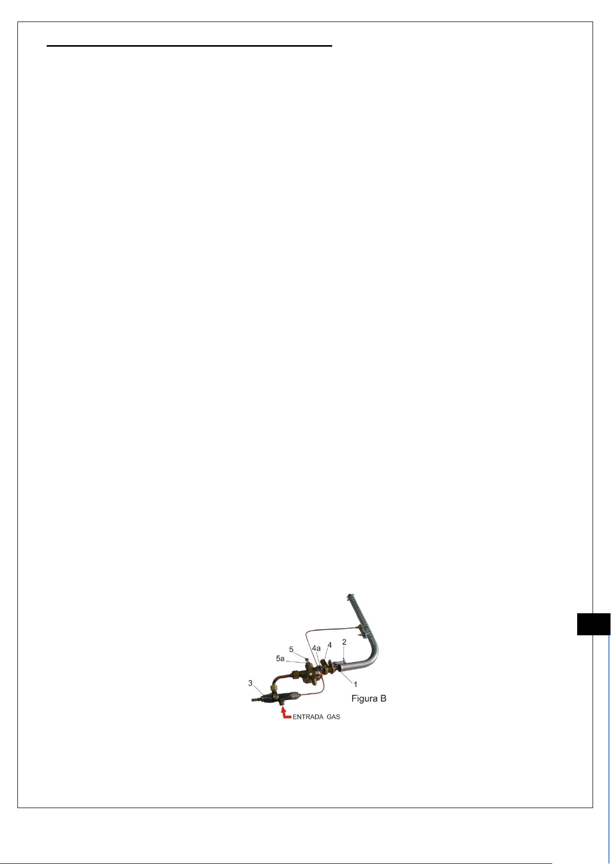
Para otro tipo de gas, desenroscar y sustituir el inyector (1) (Fig. B) por el que corresponde al tipo de gas elegido.
Según tabla adjunta. ( TABLA – A ) . Utilizar únicamente inyectores originales suministrados por el fabricante.
TABLA – A
GAS Y
PRESION
DE
FUNCIONAMIENTO
POTENCIA CALORIFICA
Kcal/h según quemador nº de
Grupos (s /Hi)
CONSUMO Y POTENCIA S/Nº GRUPOS
Ø inyector en mm.
s/nº grupos
CONSUMO
nº grupos
Potencia
KW
CONSUMO
nº grupos
Potencia
KW
CONSUMO
nº grupos
Potencia
KW
CONSUMO
nº grupos
Potencia
KW
1 2 3 4 1 2 3 4 1 2 3
4
G30 a 30
mbar
820
1890
2320
3010
70,97g/h
0,9
173,5g/h
2,2
212,9g/h
2,7
276.01g/h
3,5
0,50
0,75
0,85
1
G20 a 20
mbar
990
1890
2320
3010
0,117 m³/h
1,1
0,233 m³/h
2,2
0,286 m³/h
2,7
0,371 m³/h
3,5
0,80
1,15
1,2
1,5
Una vez hecho el cambio de gas por el instalador autorizado, modificar la placa características de la maquina
marcando el nuevo gas utilizado.
CONEXIÓN A GAS
Conectar la máquina al circuito de gas, asegurando la ausencia de fugas en el circuito. El aparato debe estar
instalado en un lugar bien ventilado para que no haya riesgo para la salud. El caudal de aire necesario para
garantizar una combustion correcta debe ser (≥ 10 m³/h) kW
La instalación de gas, agua y las conexiones, deben estar conformes a las legislaciones vigentes
Page 4

4
PRESOSTATO MODULADOR DE GAS
Controla y regula la presión del vapor en la caldera, aumentando o disminuyendo la llama del quemador, en
función de la presión de la caldera.
Las variaciones de presión actúan sobre una membrana de goma, que acciona la válvula reguladora. Esta abre y
cierra el paso principal del gas.
En derivación con el paso principal del gas, un paso mínimo permite circular una pequeña cantidad de gas, aun
cuando el paso principal esté cerrado.
NOTA: Periódicamente atornillar a fondo ( 2 ó 3 vueltas seguidas ) el tornillo del mínimo; con esta operación se
mantiene limpio el paso, propenso a obstruirse por posos debidos del flujo del gas.
Regulación del presostato modulador del gas ( Fig. B ), partiendo de la máquina fría y sin presión
a) Llenar la caldera de agua.
b) Aflojar las tuercas (4a) y (5a) cerrar completamente el tornillo (4) del mínimo del presostato
modulador del gas y abrir el tornillo del tarado (5).
c) Encender las fuentes de energía
d) Cuando la presión sea de 0,2 bar, inferior al valor deseado para el tarado (normalmente 1 bar en
máquinas semiautomáticas y 1,4 bar en máquinas a palanca ) del presostato modulador del gas,
desconectar la resistencia eléctrica, manteniendo el quemador de gas encendido.
1º Si el presostato modulador de gas está correctamente tarado, la llama del gas se apaga cuando la
aguja del manómetro caldera alcanza el valor deseado.
2º Si la llama del gas se apaga a un valor inferior al deseado, aflojar el tornillo ( 5) y volver a
encender el quemador. Repetir la operación hasta que la llama se apague cuando el manómetro
indique la presión deseada.
3º Si el tarado está demasiado alto, la llama del gas se apaga a valores superiores a los deseados.
Descargar parcialmente la presión de la caldera, apretar el tornillo ( 5 ) y volver a encender el
quemador.
e) Repetir la operación hasta que la desconexión sobrevenga a la presión deseada, y una vez finalizada la
operación bloquear la contratuerca (5a )
f) Terminada la primera fase , regular el tornillo del mínimo (4)
1º Aflojar el tornillo del mínimo ( 4 ) y volver a encender el quemador.
2º Aflojar progresivamente el tornillo del mínimo ( 4 ) hasta que la llama alcance una altura sobre el
plano del quemador de 10 mm. Aproximadamente.
3º Verificar que con esta llama, la presión indicada por el manómetro permanece constante y una
vez finalizada la operación bloquear la contratuerca ( 4a ).
NOTA: Normalmente en el caso de funcionamiento mixto gas ó electricidad, dada la mayor conveniencia del gas,
tarar el presostato a 0,8 bar y el presostato modulador de gas a 1 bar en las máquinas
semiautomáticas y automáticas; en las máquinas a palanca tarar el presostato a 1,2 bar y el presostato
modulador de gas a 1,4 bar.
MÉTODO DE VERIFICACIÓN DE FUNCIONAMIENTO DEL QUEMADOR.
La llama tiene que tener un color azul y sin bordes amarillentos.
La llama no tiene que alejarse del quemador.
Cuando el quemador se encuentra con la llama en su posición de mínimo, ésta debe alcanzar una altura sobre el
plano del quemador de 10 mm. aproximadamente
ES
Page 5

5
MANUAL PARA EL USUARIO
Solo los Servicios Técnicos Autorizados, pueden darle la máxima garantía en cuanto a servicio y recambios
originales. Exija los Recambios Originales, la Instalación y Mantenimiento al Servicio Técnico Oficial.
PRESTE ATENCIÓN A LOS RIESGOS DE ESTE APARTADO Y SUS RECOMENDACIONES DE
SEGURIDAD
● Esta máquina no tiene componentes que pueda reparar el usuario. Solo debe ser manipulada por
personal del Servicio Técnico Autorizado.
● Antes de proceder a cualquier operación de mantenimiento, dejar la máquina sin energía eléctrica
ya sea a través del interruptor general de la instalación o desconectando el cable alimentación.
● Los niños no reconocen los peligros ligados a las maquinas, por lo que deben de mantenerse
alejados de ellas e impedir que las puedan manipular.
● Las personas con las capacidades físicas, sensoriales o mentales disminuidas o el personal sin
experiencia, no deben utilizar esta máquina sin la supervisión de personal cualificado para tal fin.
● Para las operaciones de limpieza, atenerse exclusivamente a las instrucciones del presente
manual.
● Para asegurar un mejor funcionamiento de la máquina, exigir la utilización solo de Recambios
Originales, que puede suministrar el Servicio Técnico autorizado o el fabricante.
El fabricante declina toda responsabilidad, caso de incumplimiento de la legislación vigente en el lugar
de instalación de la máquina.
INSTRUCCIONES DE USO
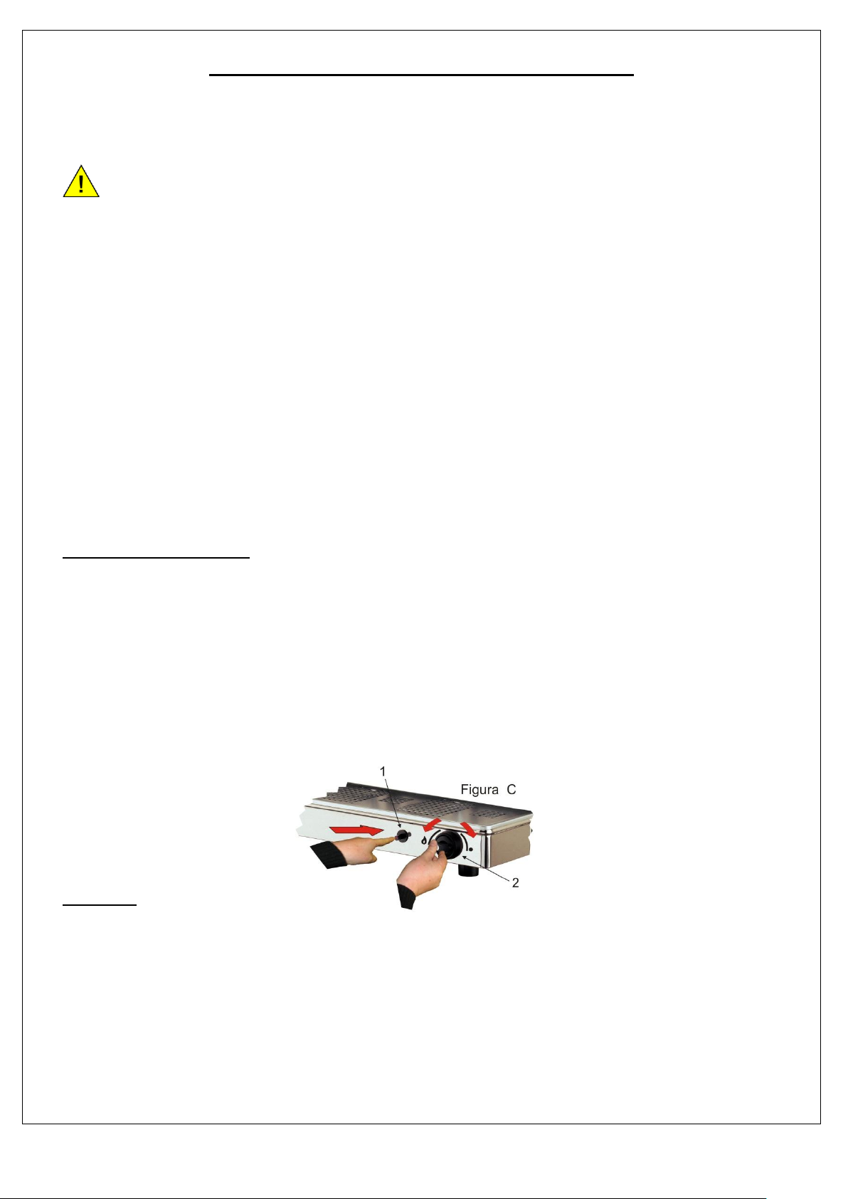
Para el encendido del quemador de gas, proceder de la siguiente manera:
1º Abrir la llave de gas general ó válvula si es botella.
2º Girar el mando gas ( 2 ) hacia la izquierda según ( Fig. C) y pulsar. Prender el quemador pulsando
el pulsador ( 1 ) manteniendo pulsado el mando gas durante 10 segundos. Soltar lentamente.
En caso de querer mantener la presión de la caldera solo con el quemador de gas, colocar el
interruptor general ( 2I, según dibujo del manual de instrucciones general según modelo de
máquina ) en la posición ( “2” ) con lo que quedará desconectada la resistencia.
Al finalizar la jornada de trabajo cerrar la aportación de gas haciendo girar el mando de gas ( 2 )
hacia la derecha hasta la posición ( • )
MANTENIMIENTO
Mantenga las zonas próximas al quemador limpias de polvo u otros elementos.
Con una periocidad semanal y ayudado de un cepillo y con el quemador apagado y frio, limpie las salidas de la
llama, así como la zona donde se ubica el termopar y la zona del inyector del presostato modulador.
Con una periocidad anual, atornillar a fondo ( 2 ó 3 vueltas seguidas ) el tornillo de regulación del mínimo.
Con esta operación se mantiene limpio el paso, propenso a obstruirse por posos debidos al fluido del gas.
No es necesario el engrasado de las llaves de paso.
ATENCION: ESTA OPERACIÓN DEBE SER REALIZADA POR UN INSTALADOR AUTORIZADO
Page 6

6
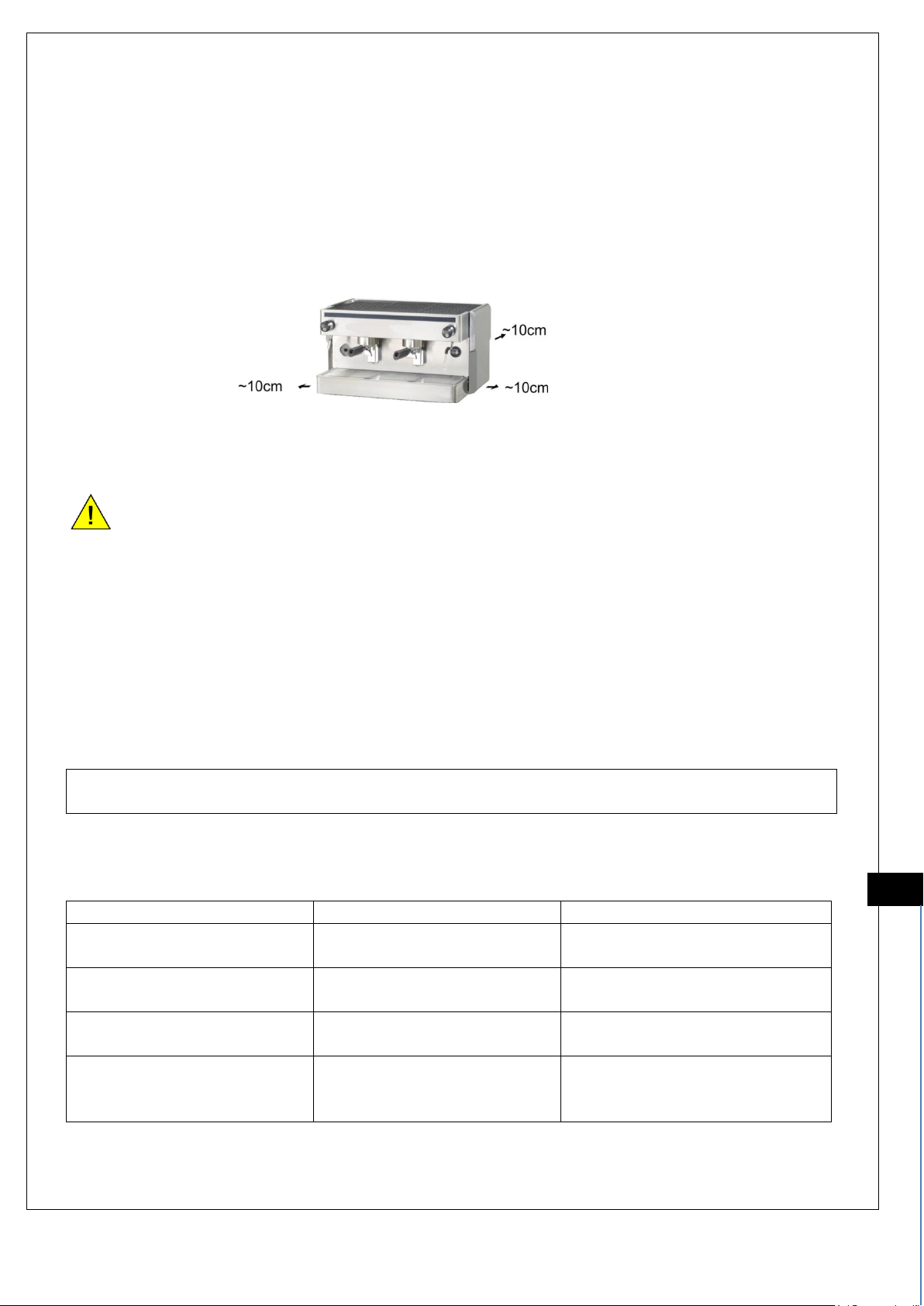
Medidas aproximadas para el espacio de ventilación de las maquinas con gas
ATENCION : El embalaje debe eliminarse de acuerdo con la reglamentación vigente
PRESTE ATENCIÓN A LOS RIESGOS DE ESTE APARTADO Y SUS RECOMENDACIONES DE
SEGURIDAD
● No almacene materiales explosivos ni inflamables cerca de la máquina.
● Mantenga las rejillas de ventilación libres de obstáculos que impidan una adecuada ventilación.
¡ATENCION¡ Si percibe olor a gas:
● Cerrar la llave del gas
● No accionar ningún interruptor eléctrico
● No usar el teléfono en la zona de peligro
● Abrir ventanas y airear el local
● Llame inmediatamente al Servicio Técnico
EL FABRICANTE DECLINA TODA RESPONSABILIDAD POR UN MAL USO DEL EQUIPO
AVERIAS
POSIBLES CAUSAS
OBSERVACION
l quemador no se enciende
No llega gas a la máquina
Comprobar que la llave de paso o
válvula de la botella está abierta
El quemador se apaga cuando
se suelta el mando de gas (2)
El termopar está averiado o
desajustado
Avisar a un instalador autorizado
La llama mínimo no se
mantiene
Presostato modulador de gas
está desajustado o averiado
Avisar a un instalador autorizado
La llama tiene un color amarillo
y la caldera se ahúma
Regulador aire desajustado o
presostato modulador de gas
desajustado
Avisar a un instalador autorizado
ES
Page 7

7
MANUAL FOR THE AUTHORIZED INSTALLER
We recommend closely following the instructions in this manual. Any irregularity encountered during installation
or maintenance should be reported to Authorized Technical Service.
CAREFULLY READ THE RISKS AND SAFETY GUIDELINES IN THIS SECTION
● All the connections should be made with the general gas key closed.
● The connection tube should be one piece from the stopcock to the machine intake.
● Once the connections have been established a check should be done to ensure there are no gas leaks.
The manufacturer accepts no responsibility in the case of failure to comply with the valid legislation
in the location where the machine is installed.
INSTRUCTIONS FOR INSTALLATION OF MODELS WITH BUILT IN GAS
TECHNICAL STANDARDS
The espresso machines comply with regulations UNE-EN 203-1:2006+A1:2008 and UNE-EN 203-2-6:2006
ATTENTION: The pressure of the water inlet should be between Max. 0.5 and Min. 0.2 MPas.
The machine should be installed according to Regulation EN 1717 (Protection against potable water pollution).
The gas installation should comply with the current valid legislation and safety regulations applicable in the
region/country where it is installed.
The gas installation shall incorporate a stopcock for exclusive machine use.
To carry out the gas installation, the machine is outfitted with an adapter for the connection of a standardized 9
mm interior diameter tube.
ATTENTION: It is important to pay attention to the expiration date of the connection tube in accordance with
what the current valid legislation indicates.
For the machines with built-in gas equipment that are installed with gas, keep in mind that the machine is set up
for BUTANE GAS (G30). If another type of gas is used follow these instructions:
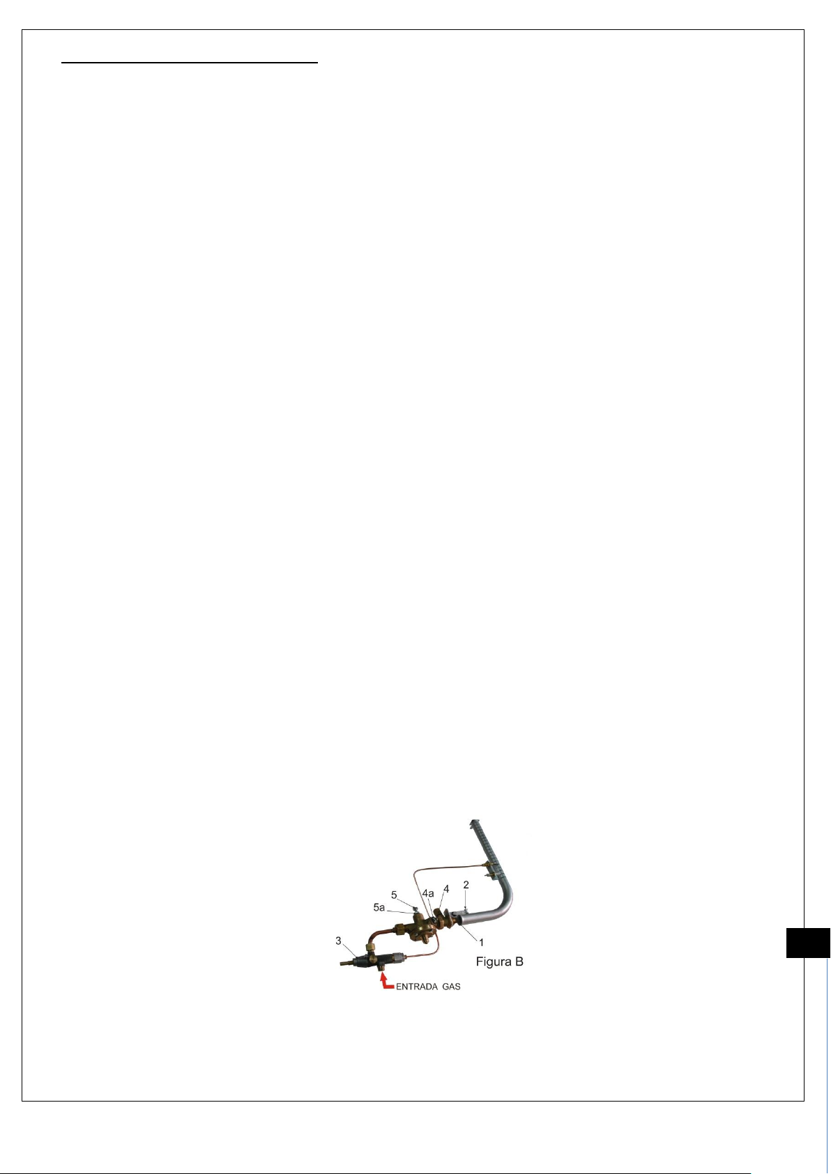
For other types of gas, unscrew and replace the injector (1) (Fig. b) with one suited to the type of gas selected,
according to the table (TABLE – A) below. Use only original injectors supplied by the manufacturer.
TABLE – A
GAS AND
OPERATIONAL
PRESSURE
HEAT RATE
Kcal/h according to burner
Group No. (per/Hi)
USAGE AND POWER ACCORDING TO GROUP No.
Ø injector in mm.
per group No.
USAGE
No. groups
Power
KW
USAGE
No. groups
Power
KW
USAGE
No. groups
Power
KW
USAGE
No. groups
Power
KW
1 2 3 4 1 2 3 4 1 2 3
4
G30 to 30
mbar
820
1890
2320
3010
70.97g/h
0.9
173.5g/h
2.2
212.9g/h
2.7
276.01g/h
3.5
0.50
0.75
0.85
1
G20 to 20
mbar
990
1890
2320
3010
0.117 m³/h
1.1
0.233 m³/h
2.2
0.286 m³/h
2.7
0.371m³/h
3.5
0.80
1.15
1.2
1.5
Once the gas change is completed by the authorized installer, update the machine´s data sheet by noting the
new type of gas used.
GAS CONNECTION
Connect the machine to the gas circuit, checking to make sure there are no leaks in the circuit. The device
should be installed in a well-ventilated place to avoid health risks. The necessary airflow should be (≥ 10 m³/h)
kW to ensure correct combustion.
The installation of gas and water and the connections should comply with the current valid legislation
Page 8

8
GAS REGULATOR PRESSURE SWITCH
Control and regulate the steam pressure in the boiler, increasing or decreasing the burner flame according to the
steam boiler pressure.
The pressure changes act on a rubber membrane, which triggers the regulating valve. This opens and closes
the main gas passage.
In addition to the main gas passage, a smaller passage permits a small quantity of gas to circulate, even when
the main passage is closed.
NOTE: Periodically tighten (2 or 3 full rotations) the screw of the smaller passage so as to keep the passage
clear, as it tends to get obstructed by residue from the gas flow.
Adjustment of the gas pressure switch ( Fig. B ), starting with the machine cold and without pressure
a) Fill the boiler with water.
b) Loosen the nuts (4a) and (5a) completely tighten the screw (4) of the smaller passage of the gas
regulator pressure switch and loosen the calibration screw (5).
c) Turn on the power sources.
d) When the pressure reaches 0.2 bars, less than the desired value for the calibration (normally 1 bar for
semi-automatic machines and 1.4 for lever machines) of the gas regulator pressure switch, disconnect
the electrical resistance, keeping the gas burner lit.
1st If the gas regulator pressure switch is correctly calibrated, the gas flame will go out when the water
from the boiler pressure gauge reaches the desired value.
2nd If the gas flame goes out at a lower value than desired, loosen the screw (5) and turn on the burner
again. Repeat the procedure until the flame goes out when the pressure gauge reads the desired
pressure.
3rd If the calibration is too high, the gas flame will go out at higher levels than desired. Partially
decrease the boiler pressure, tighten the screw (5) and turn the burner on again.
e) Repeat the procedure until the disconnection reaches the desired pressure, and once the procedure is
complete lock the locknut (5a).
f) Once the first phase is complete, adjust the screw of the smaller passage (4).
1st Loosen the screw of the smaller passage (4) and turn the burner on again.
2nd Gradually loosen the screw of the smaller passage (4) until the flame reaches a height over the
burner surface of approximately 10 mm.
3rd Verify that with this flame the pressure read on the pressure gauge is constant, and once the
procedure is complete lock the locknut (4a).
NOTE: Normally, if using mixed gas and electricity, calibrate the pressure gauge to 0.8 bars and the gas
regulator pressure switch to 1 bar for semi-automatic and automatic machines; in lever machines, calibrate the
pressure gauge to 1.2 bars and the gas regulator pressure switch to 1.4 bars.
VERIFICATION OF BURNER FUNCTIONING.
The flame must be blue in colour with yellowish edges.
The flame should not be far from the burner.
When the burner flame is at its minimum position, the flame should reach a height of approximately 10 mm
above the burner surface.
GB
Page 9

9
USER MANUAL
Only Authorized Serviced Technicians are qualified to provide the maximum guarantee with regard to service
and original replacement parts. Request Original Replacement Parts, Installation and Maintenance from
Official Technical Service.
CAREFULLY READ THE RISKS AND SAFETY GUIDELINES IN THIS SECTION
● This machine does not have components for the user to make repairs. It can only be manipulated
by personnel from Authorized Technical Service.
● Before starting any maintenance procedure, cut off the electricity either through the general
installation switch or disconnecting the electricity supply cable.
● Children do not recognize the dangers of machines, thus they should be kept out of their reach and
they should be prevented from handling the machines.
● Individuals with diminished physical, sensory or mental capacities, or who are untrained, should not
operate this machine without the supervision of qualified personnel.
● To clean the machine, follow the instructions in this manual.
● To ensure the optimum functioning of the machine, request that only Original Replacement Parts are
used, which can be supplied by authorized Technical Service or the manufacturer.
The manufacturer accepts no responsibility in the case of failure to comply with the valid legislation in
the location where the machine is installed.
INSTRUCTIONS
To turn on the gas burner, follow these instructions:
1st Open the general gas key or valve if it is bottled gas.
2nd Turn the gas switch (2) to the left (as indicated in Fig. C) and press. Turn on the burner pressing the
button (1) and maintaining it for 10 seconds. Release slowly.
If you want to maintain the pressure in the boiler with the gas burner alone, turn the general switch
(2I, as indicated in the general instruction manual drawing according to the machine model) to
position (“2”) which will disconnect the resistance.
At the end of the work day shut off the gas supply by turning the gas switch (2) to the right to position
(•).
MAINTENENCE
Keep the areas immediately surrounding the burner clean and dust-free.
Once a week, with the burner turned off and cooled, clean the flame outlets as well as the areas around the
thermocouple and the pressure switch regulator injector with a brush.
This will keep the passage clear, as it tends to become obstructed by residue from the gas flow.
It is not necessary to grease the stopcocks.
ATTENTION: THIS PROCEDURE SHOULD BE PERFORMED BY AN AUTHORIZED INSTALLER
Page 10
10
Approximate measurements for ventilation space for machines with gas
ATTENTION: Packaging should be disposed of in accordance with the applicable regulations.
CAREFULLY READ THE RISKS OF AND SAFETY GUIDELINES IN THIS SECTION
● Keep explosive and flammable materials at a safe distance from the machine.
● Keep ventilation vents unblocked so as not to hinder adequate ventilation.
ATTENTION! If you detect the smell of gas:
● Close the gas key
● Do not turn on any electrical switches
● Do not use the telephone in the area
● Open the windows and air out the area
● Call Technical Service Immediately
THE MANUFACTURER ACCEPTS NO RESPONSIBILITY IN THE CASE OF IMPROPER
USOFTHE EQUIPMENT
PROBLEM
POSSIBLE CAUSES
COMMENTS
The burner does not turn on
Gas is not reaching the
machine
Check that the stopcock or bottled
gas valve is open
The burner turns off when the
gas switch is released (2)
The thermocouple is broken or
loose
Contact an authorized installer
The minimum flame will not
stay lit
The gas regulator pressure
switch is loose or broken
Contact an authorized installer
The flame is yellow - coloured
and the boiler is smoking
The air regulator is loose or the
gas regulator pressure
switch is loose
Contact an authorized installer
GB
Page 11

11
MANUEL DE L’INSTALLATEUR AGRÉÉ
Il est recommandé de suivre fidèlement les indications rassemblées dans ce manuel et de vous rappeler de
communiquer au Service Après Vente toute anomalie que vous pourriez rencontrer pendant les processus
d’installation ou de maintenance.
FAITES ATTENTION AUX RISQUES ET AUX RECOMMANDATIONS DE CE PARAGRAPHE
DE SÉCURITÉ
● Tous les raccordements doivent être effectués avec le robinet de gaz fermé.
● Le tuyau de raccordement doit être constitué d’une seule pièce depuis le robinet à la prise de la machine.
● Une fois les raccordements effectués vous devez vérifier l’absence de fuites de gaz dans l’installation
terminée
Le fabricant décline toute responsabilité en cas de violation de la législation en vigueur
dans le lieu d’installation de la machine.
INSTRUCTIONS POUR L’INSTALLATION DES MODÈLES AVEC GAZ INTÉGRÉ
NORMES TECHNIQUES
Les machines à café se conforment aux normes UNE-EN 203-1 : 2006+ A1 : 2008 et UNE-EN 203-2-6 : 2006
ATTENTION : La pression d’entrée de l’eau doit être au maximum entre 0,5 et 0,2 Mpa au minimum.
La machine doit être installée selon la norme EN 1717 (Protection contre la contamination de l’eau potable).
Le système de gaz devra être conforme à la législation et aux normes de sécurité en vigueur dans le lieu
d’installation de la machine.
Le système de gaz doit comporter un robinet d’arrêt à usage exclusif de la machine.
Pour établir le raccordement au système de gaz, la machine est fournie avec un raccord pour la connexion d’un
tuyau agréé d’un diamètre intérieur de 9 mm.
ATTENTION : Rappelez-vous de respecter les périodes d’expiration du tuyau de connexion selon la législation en
vigueur
Pour les machines avec équipement de gaz intégré et qui s’installent avec cette énergie, vous devez prendre en
compte que la machine soit prévue pour du GAZ BUTANE (G30). Si vous utilisez un autre type de gaz, suivez les
instructions ci-dessous :
Pour un autre type de gaz, dévissez et remplacez l’injecteur (1) (Fig. B) par celui qui correspond au type de gaz
choisi. Selon le tableau suivant. (TABLEAU – A). Utilisez uniquement les injecteurs originaux fournis par le
fabricant
TABLEAU-A
GAS ET
PRESSION
DE
FONCTION
NEMENT
PUISSANCE THERMIQUE
Kcal/h selon brûleur n˚ de
Groupes (s/Hi)
CONSOMMATION ET PUISSANCE SELON N˚ GROUPES
Ø injecteur en mm.
s/nº groupes
CONSOM.
nº groupes
Puissance
KW
CONSOM.
nº groupes
Puissance
KW
CONSOM.
nº groupes
Puissance
KW
CONSOM.
nº groupes
Puissance
KW
1 2 3 4 1 2 3 4 1 2 3
4
G30 à 30
mbar
820
1890
2320
3010
70,97g/h
0,9
173,5g/h
2,2
212,9g/h
2,7
276,01g/h
3,5
0,50
0,75
0,85
1
G20 à 20
mbar
990
1890
2320
3010
0,117 m³/h
1,1
0,233 m³/h
2,2
0,286 m³/h
2,7
0,371 m³/h
3,5
0,80
1,15
1,2
1,5
Une fois effectué le changement de gaz par l’installateur agréé, modifier les caractéristiques de la plaque en
indiquant le nouveau gaz utilisé.
RACCORDEMENT AU GAZ
Connectez la machine au circuit de gaz, en vous assurant de l’absence de fuites dans le circuit. L’appareil doit
être installé dans un endroit bien ventilé pour éviter tout risque pour la santé. Le débit de l’air nécessaire pour garantir
une combustion correcte doit être (≥ 10 m³/h) kW
L’installation du gaz, de l’eau et des raccordements doivent être conformes aux législations en vigueur.
Page 12
12
PRESSOSTAT MODULATEUR DE PRESSION DE GAZ
Il contrôle et régule la pression de la vapeur dans la chaudière, en augmentant ou diminuant la flamme du brûleur,
en fonction de la pression de la chaudière.
Les variations de pression agissent sur une membrane de caoutchouc, laquelle active la soupape régulatrice de
pression. Celle-ci ouvre et ferme le passage principal du gaz.
En dérivation avec le débit de gaz principal, un débit minimal permet de faire circuler une petite quantité de gaz,
même si le débit principal est fermé.
NOTE : Régulièrement, vissez à fond (2 ou 3 tours consécutifs) la vis du débit minimal. Avec cette opération le
robinet restera propre car il a tendance à se boucher à cause des dépôts dus au flux du gaz.
Réglage du pressostat modulateur de pression du gaz (Fig. B), à partir de la machine à froid et sans
pression
a) Remplissez la chaudière avec de l’eau.
b) Desserrez les écrous (4ª) et (5ª) fermez complètement la vis (4) du débit minimal du pressostat
modulateur de gaz et ouvrez la vis d’étalonnage (5).
c) Allumez les sources d’énergie
d) Lorsque la valeur est de 0,2 bar, en-dessous de la valeur souhaitée pour l’étalonnage (normalement 1 bar
dans les machines semi-automatiques et 1,4 bars dans les machines à levier) du pressostat modulateur de
gaz, déconnectez la résistance électrique, en gardant le brûleur de gaz allumé.
1º Si le pressostat modulateur de gaz est étalonné correctement, la flamme du gaz s’éteint quand
l’aiguille du manomètre de la chaudière atteint la valeur souhaitée.
2º Si la flamme du gaz s’éteint à une valeur inférieure à celle souhaitée, desserrez la vis (5) et
rallumez le brûleur. Refaites l’opération jusqu’à ce que la flamme s’éteigne quand le manomètre
indique la pression souhaitée.
3º Si l’étalonnage est trop élevé, la flamme du gaz s’éteint à des valeurs supérieures à celles
souhaitées. Déchargez partiellement la pression de la chaudière, serrez la vis (5) et rallumez le
brûleur.
g) Répétez l’opération jusqu’à ce que la déconnexion se produise à la pression souhaitée, et une fois
l’opération finalisée bloquez le contre-écrou (5a)
h) la première phase étant terminée, réglez la vis du débit minimal (4)
1º Desserrez la vis du débit minimal (4) et rallumez le brûleur.
2º Desserrez progressivement la vis du débit minimal (4) jusqu’à ce que la flamme atteigne une hauteur
au-dessus du plan du brûleur de 10 mm environ.
3º Vérifiez qu’avec cette flamme la pression indiquée par le manomètre reste constante et une fois
l’opération terminée, bloquez le contre-écrou (4a).
NOTE : Normalement, dans le cas d’un fonctionnement mixte au gaz ou électricité, compte tenu de la commodité
du gaz, étalonnez le pressostat à 0.8 bar et le pressostat modulateur de gaz à 1 bar dans les machines
semi-automatiques et automatiques; dans les machines à levier étalonnez le pressostat de à 1,2 bars et
le pressostat +modulateur de gaz à 1,4 bars.
MÉTHODE DE VÉRIFICATION DE FONCTIONNEMENT DU BRÛLEUR.
La flamme doit avoir une couleur bleue et sans bords jaunâtres.
La flamme ne doit pas s’éloigner du brûleur.
Quand la flamme du brûleur se trouve en position minimale, elle doit atteindre une hauteur au-dessus du plan du
brûleur de 10 mm environ.
FR
Page 13

13
MANUEL DE L’UTILISATEUR
Seuls les Services Techniques Agréés peuvent vous offrir le maximum de garantie en termes de service et pièces
de rechange originales. Exigez des Pièces de Rechange Originales, l’Installation et la Maintenance par le Service
Technique Officiel.
FAITES ATTENTION AUX RISQUES ET RECOMMANDATIONS DE SÉCURITÉ DE CE PARAGRAPHE
● Cette machine n’a pas de composants pouvant être réparés par l’utilisateur. Elle doit être manipulée
uniquement par le personnel du Service Technique Agréé.
● Avant de procéder à toute opération de maintenance, veuillez déconnectez la machine
soit avec l’interrupteur général de l’installation soit en déconnectant le câble d’alimentation
● Les enfants ne se rendent pas compte des dangers liés aux machines, ils doivent donc être gardés
éloignés d’elles afin d’empêcher leur manipulation.
● Les personnes souffrant de handicaps physiques, sensoriels ou mentaux ou le personnel
inexpérimenté ne doivent pas utiliser cette machine sans le contrôle de personnel qualifié.
● Pour les opérations de nettoyage, conformez-vous exclusivement aux instructions de ce manuel.
● Pour garantir un meilleur fonctionnement de la machine, exigez uniquement l’utilisation de Pièces de
Rechange Originales, fournies par le Service Technique Agréé ou le fabricant.
Le fabricant décline toute responsabilité en cas de violation de la législation en vigueur dans le lieu
d’installation de la machine.
INSTRUCTIONS D’USAGE
Pour l’allumage du brûleur de gaz, procédez de la manière suivante :
1º Ouvrez le robinet de gaz général ou le clapet s’il est en bouteille.
2º Tournez la commande du gaz (2) vers la gauche selon (Fig. C) et appuyez. Allumez le brûleur en
appuyant sur le bouton-poussoir (1) en maintenant appuyée la commande du gaz pendant
10 secondes. Lâchez doucement.
Dans le cas où vous voulez maintenir la pression de la chaudière uniquement avec le brûleur de gaz,
placez l’interrupteur général (2I, selon le dessin du manuel d’instructions général du modèle de la
Machine) dans la position (« 2 ») ce qui gardera la résistance déconnectée.
À la fin de la journée de travail, fermez l’entrée de gaz en tournant la commande de gaz (2)
vers la droite jusqu’à la position ( • )
MAINTENANCE
Veillez à maintenir les zones proches du brûleur sans poussière ou autres éléments.
Chaque semaine et avec l’aide d’une brosse, le brûleur éteint et froid, nettoyez les sorties de la flamme, ainsi que
la zone où se trouve le thermocouple et la zone de l’injecteur du pressostat modulateur.
Chaque année, vissez à fond (2 ou 3 tours consécutifs) la vis de régulation du débit minimal.
Grâce à cette opération, le robinet reste propre, car il a tendance à se boucher à cause des dépôts dus au flux du gaz.
Il n’est pas nécessaire de graisser les robinets d’arrêt.
ATTENTION : CETTE OPÉRATION DOIT ÊTRE RÉALISÉE PAR UN INSTALLATEUR AGRÉÉ
Page 14

14
Mesures approximatives pour l’espace de ventilation des machines à gaz
ATTENTION : L’emballage doit être éliminé conformément à la règlementation en vigueur.
FAITES ATTENTION AUX RISQUES ET RECOMMANDATIONS DE SÉCURITÉ DE CE PARAGRAPHE
● N’entreposez pas de matériels explosifs ni inflammables près de la machine.
● Maintenez les grilles d’aération sans obstacles car ils empêcheraient une ventilation appropriée.
ATTENTION ! Si vous sentez une odeur de gaz :
● Fermez le robinet de gaz
● N’actionnez aucun interrupteur électrique
● N’utilisez pas de téléphone dans la zone de danger
● Ouvrez les fenêtres et aérez le local
● Appelez immédiatement le service technique
LE FABRICANT DÉCLINE TOUTE RESPONSABILITÉ EN CAS DE MAUVAISE UTILISATION DE
L’ÉQUIPEMENT
LPANNES
CAUSES POSSIBLES
OBSERVATIONS
Le brûleur ne s’allume pas
Le gaz n’arrive pas à la
machine
Vérifiez que le robinet ou le clapet
de la bouteille est ouvert
Le brûleur s’éteint quand la
commande de gaz est lâchée (2)
Le thermocouple est en panne
ou déréglé
Appelez un installateur agréé
La flamme minimale ne se
maintient pas
Le pressostat modulateur de
gaz est déréglé ou en panne
Appelez un installateur agréé
La flamme a une couleur
jaunâtre et la chaudière fume
Le régulateur d’air ou le
pressostat modulateur de gaz
est déréglé
Appelez un installateur agréé
FR
Page 15

15
MANUALE DI ISTRUZIONI PER L’INSTALLATORE AUTORIZZATO
Si raccomanda di seguire fedelmente le indicazioni contenute nel presente manuale e di comunicare al Centro di
Assistenza Tecnica ogni eventuale anomalia che si dovesse verificare durante il processo di istallazione o
manutenzione.
SI PREGA DI PRESTARE LA MASSIMA ATTENZIONE AI RISCHI DI SEGUITO INDICATI
COMPRESE LE AVVERTENZE DI SICUREZZA
● Prima di effettuare qualsiasi tipo di collegamento, chiudere il rubinetto generale del gas.
● Il tubo di collegamento deve comporsi di un unico pezzo; dal rubinetto di arresto alla presa della macchina.
● Una volta eseguiti i collegamenti, è necessario verificare che l’impianto non presenti fughe di gas.
Il fabbricante declina ogni responsabilità per casi di violazione della normativa vigente nel luogo di
installazione della macchina.
ISTRUZIONI PER L’INSTALLAZIONE DI MODELLI CON GAS INCORPORATO
NORMATIVA TECNICA
Le nostre macchine da caffè sono conformi alle norme UNE-EN 203-1:2006+A1:2008 e UNE-EN 203-2-6:2006.
ATTENZIONE:
La pressione di ingresso dell’acqua deve essere compresa fra un max. di 0,5 MPa e un min. di 0,2 MPa.
La macchina deve essere installata secondo la normativa EN 1717 (Protezione contro l’inquinamento dell’acqua potabile).
L’allacciamento alla rete gas deve avvenire in ottemperanza sia della legislazione che delle disposizioni di
sicurezza vigenti nel luogo di installazione della macchina.
L’allacciamento alla rete gas deve prevedere un rubinetto di arresto esclusivo per la macchina.
Per l’allacciamento alla rete gas, la macchina ha in dotazione un raccordo per il collegamento di un tubo
omologato dal diametro interno di 9 mm.
ATTENZIONE: È essenziale rispettare il periodo di scadenza del tubo di collegamento così come indicato dalla
legislazione vigente.
Per macchine con impianto del gas incorporato ed installate per essere alimentate da tale fonte di energia, si
deve tener presente che l’apparecchio è predisposto per GAS BUTANO (G30). Qualora si utilizzi un tipo di gas
diverso, occorre osservare le seguenti istruzioni:
Svitare e sostituire l’iniettore (1) (Fig. B) con uno adeguato al tipo di gas in questione. Cfr. tabella sottostante
(TABELLA – A). Usare unicamente iniettori originali forniti dal fabbricante.
TABELLA – A
GAS E
PRESSIONE DI
ESERCIZIO
POTENZA TERMICA
Kcal/h secondo bruciatore e
n. gruppi (s /Hi)
CONSUMO E POTENZA SECONDO N. GRUPPI
Ø iniettore in mm.
secondo n. gruppi
CONSUMO
n. gruppi
Potenza
KW
CONSUMO
n. gruppi
Potenza
KW
CONSUMO
n. gruppi
Potenza
KW
CONSUMO
n. gruppi
Potenza
KW
1 2 3 4 1 2 3 4 1 2 3
4
G30 a 30
mbar
820
1890
2320
3010
70,97g/h
0,9
173,5g/h
2,2
212,9g/h
2,7
276.01g/h
3,5
0,50
0,75
0,85
1
G20 a 20
mbar
990
1890
2320
3010
0,117 m³/h
1,1
0,233 m³/h
2,2
0,286 m³/h
2,7
0,371 m³/h
3,5
0,80
1,15
1,2
1,5
Una volta effettuato il cambio ad opera dell’installatore autorizzato, modificare l’etichetta di identificazione della
macchina specificando il tipo di gas utilizzato.
COLLEGAMENTO ALLA RETE GAS
Collegare la macchina alla rete, assicurandosi che non ci siano fughe di gas. L’apparecchio deve essere installato
in un punto ben ventilato, in modo da evitare rischi per la salute. La portata d’aria necessaria a garantire una
corretta combustione dovrà essere non inferiore a (≥ 10 m³/h) kW.
L’allacciamento all’impianto del gas e dell’acqua così come ogni altro tipo di collegamento
devono essere conformi alle norative vigenti.
Page 16

16
PRESSOSTATO GAS A MODULAZIONE
Serve a controllare e regolare la pressione del vapore nella caldaia, aumentando o riducendo la fiamma del
bruciatore in funzione ad essa.
Le variazioni di pressione si ripercuotono su una membrana di gomma che aziona la valvola di regolazione.
Questa, a propria volta, apre e chiude il condotto di alimentazione principale del gas.
In derivazione al condotto principale del gas, un condotto di alimentazione minima permette l’afflusso di una
quantità ridotta di gas anche quando il condotto principale è chiuso.
NOTA: Con periodicamente, avvitare a fondo (2 o 3 giri di seguito) la vite di regolazione del minimo; in questo
modo, si mantiene pulito il condotto, soggetto a ostruirsi a causa dei depositi lasciati dal flusso di gas.
Regolazione del pressostato gas a modulazione (Fig. B), da effettuare con la macchina fredda e senza
pressione
a) Riempire d’acqua la caldaia.
b) Allentare i dadi (4a) e (5a), chiudere completamente la vite del minimo (4) del pressostato gas a
modulazione e aprire la vite per la taratura (5).
c) Accendere le fonti di energia.
d) Quando la pressione raggiunge un valore di 0,2 bar inferiore a quello previsto per la taratura del
pressostato gas a modulazione (generalmente 1 bar per le macchine semiautomatiche e 1,4 bar per i
modelli a leva), scollegare la resistenza elettrica e lasciare acceso il bruciatore di gas.
1º Se il pressostato gas a modulazione è tarato correttamente, la fiamma si spegnerà quando la
lancetta del manometro della caldaia segnerà il valore prefissato.
2º Se la fiamma si spegne in corrispondenza di un valore inferiore a quello prestabilito, allentare la
vite (5) e riaccendere il bruciatore. Ripetere l’operazione fino a far sì che la fiamma si spenga quando
il manometro indica la pressione stabilita.
3º Se il pressostato è tarato su un valore troppo alto, la fiamma si spegnerà una volta raggiunta
una pressione superiore a quella desiderata. Scaricare parzialmente la pressione della caldaia,
stringere la vite (5) e riaccendere il bruciatore.
i) Ripetere l’operazione fino ad ottenere la disattivazione del bruciatore in corrispondenza della pressione
voluta, poi serrare il controdado (5a).
j) Conclusa la prima fase, regolare la vite del minimo (4).
1º Allentare la vite del minimo (4) e riaccendere il bruciatore.
2º Allentare progressivamente la vite del minimo (4) fino a ottenere una fiamma alta circa 10 mm
rispetto al piano del bruciatore.
3º Verificare che con questa fiamma la pressione indicata dal manometro si mantenga constante, poi
serrare il controdado (4a).
NOTA: In considerazione della maggiore convenienza del gas, nelle macchine a funzionamento misto, a gas o
elettrico, si consiglia la seguente taratura: nel caso di apparecchi semiautomatici o automatici, pressostato
a 0,8 bar e pressostato gas a modulazione a 1 bar; in caso di modelli a leva, pressostato a 1,2 bar e
pressostato gas a modulazione a 1,4 bar.
VERIFICA DEL CORRETTO FUNZIONAMENTO DEL BRUCIATORE
La fiamma deve essere azzurra e non avere bordi tendenti al giallo.
La fiamma non deve allontanarsi dal bruciatore.
Quando è al minimo, la fiamma deve raggiungere un’altezza di circa 10 mm. rispetto al piano del bruciatore.
Page 17

17
MANUALE DI ISTRUZIONI PER L’UTENTE
Solo i Centri di Assistenza Tecnica autorizzati possono offrire l’assoluta garanzia di qualità del servizio e fornire
pezzi di ricambio originali. Per i ricambi, l’installazione e la manutenzione, rivolgersi sempre a un Centro di
Assistenza Tecnica Ufficiale.
SI PREGA DI PRESTARE LA MASSIMA ATTENZIONE AI RISCHI QUI DESCRITTI E ALLE
AVVERTENZE DI SICUREZZA
● Nessuno dei componenti di questa macchina può essere riparato dall’utente. L’apparecchio
deve essere maneggiato unicamente dal personale del Servizio di Assistenza Tecnica Autorizzato.
● Prima di qualsiasi intervento di manutenzione, scollegare l’apparecchio dalla rete elettrica, spegnendo
l’interruttore generale dell’impianto o staccando il cavo di alimentazione.
● I bambini non riconoscono i pericoli potenziali di una macchina. Pertanto, non gli si deve permettere
di avvicinarsi e toccarla.
● L’apparecchio non è destinato a essere utilizzato da persone con ridotte capacità fisiche, sensoriali o
mentali, o prive della sufficiente esperienza e conoscenza, senza la supervisione di personale
qualificato.
● Per la pulizia della macchina, attenersi esclusivamente alle istruzioni fornite dal presente manuale.
● A garanzia di un migliore funzionamento dell’apparecchio, richiedere sempre pezzi di ricambio
originali, che possono essere forniti dal Centro di Assistenza Tecnica Autorizzato o dal produttore.
Il fabbricante declina ogni responsabilità per casi di violazione della normativa vigente nel luogo di
installazione della macchina.
ISTRUZIONI PER L’USO
Per accendere il bruciatore di gas, procedere come segue:
1º Aprire il rubinetto generale del gas o la valvola, qualora si tratti di una bombola.
2º Ruotare il comando del gas (2) verso sinistra (cfr. Fig. C) e premere. Accendere il bruciatore usando
il pulsante (1) e tenere premuto il comando del gas per 10 secondi. Rilasciare lentamente.
Se si desidera mantenere la pressione della caldaia solo con il bruciatore di gas, posizionare
l’interruttore generale (2I, secondo il disegno del manuale generale di istruzioni del modello
corrispondente alla propria macchina) sul ("2"), in modo da scollegare la resistenza.
Alla fine della giornata di lavoro, bloccare l’afflusso di gas ruotando il comando del gas (2) verso destra
fino a portarlo nella posizione contrassegnata dal punto (•).
MANUTENZIONE
Mantenere pulita da polvere o elementi di altro tipo l’area circostante al bruciatore.
Una volta alla settimana, usando una spazzola e facendo attenzione che il bruciatore sia spento e freddo, pulire i
fori di uscita della fiamma, la zona della termocoppia e quella dell’iniettore del pressostato a modulazione.
Una volta all’anno, avvitare a fondo (2 o 3 giri di seguito) la vite di regolazione del minimo.
In questo modo, si mantiene pulito il condotto, incline a ostruirsi a causa dei depositi lasciati dal flusso di gas.
Non è necessaria la lubrificazione dei rubinetti di arresto.
ATTENZIONE: QUESTA OPERAZIONE DEVE ESSERE ESEGUITA DA UN INSTALLATORE AUTORIZZATO
Page 18

18
Misure approssimative dello spazio necessario a garantire una corretta ventilazione di un apparecchio a gas:
ATTENZIONE: Lo smaltimento dell’imballaggio deve avvenire in conformità alle normative vigenti.
SI PREGA DI PRESTARE LA MASSIMA ATTENZIONE AI RISCHI QUI DESCRITTI E ALLE
AVVERTENZE DI SICUREZZA
● Non conservare materiale esplosivo o infiammabile in prossimità della macchina.
● Mantenere le griglie di ventilazione libere da ostacoli che ne impediscano un’adeguata ventilazione.
ATTENZIONE! Se si sente odore di gas:
● Chiudere il rubinetto principale
● Non azionare nessun interruttore elettrico
● Non utilizzare il telefono nella zona di pericolo
● Aprire le finestre e arieggiare il locale
● Chiamare immediatamente il Centro di Assistenza Tecnica
IL FABBRICANTE DECLINA OGNI RESPONSABILITÀ PER UN USO IMPROPRIO DELL’APPARECCHIO
AVARIE
POSSIBILI CAUSE
OSSERVAZIONI
Il bruciatore non si accende
Non arriva gas alla macchina
Controllare che il rubinetto di arresto o
la valvola della bombola siano aperti
Il bruciatore si spegne quando si
rilascia il comando del gas (2)
Termocoppia guasta o non
regolata correttamente
Rivolgersi a un installatore autorizzato
La fiamma minima non è stabile
Pressostato gas a modulazione
non regolato correttamente o
guasto
Rivolgersi a un installatore autorizzato
La fiamma è gialla e la caldaia si
riempie di fumo
Regolatore dell’aria o pressostato
gas a modulazione non regolati
correttamente
Rivolgersi a un installatore autorizzato
Page 19

19
BEDIENUNGSANLEITUNG FÜR ZUGELASSENE INSTALLATEURE
Es wird empfohlen die in dieser Bedienungsanleitung enthaltenen Anweisungen genau zu befolgen und darauf
hingewiesen, dass dem Technischen Dienst jegliche Anomalie mitgeteilt werden muss, die während des
Installationsprozesses oder der Wartungsarbeiten festgestellt wird.
ACHTEN SIE AUF DIE GEFAHREN DIESES GERÄTS UND DIE SICHERHEITSRATSCHLÄGE
● Alle Verbindungen und Anschlüsse müssen mit geschlossener Hauptabsperreinrichtung der Gasleitung
durchgeführt werden.
● Das Verbindungsrohr muss aus einem einzigen Stück bestehen, vom Absperrventil bis zum Anschlussteil
der Kaffeemaschine.
● Nachdem die Anschlüsse vorgenommen worden sind, ist zu überprüfen, ob die Gasinstallation undichte
Stellen aufweist.
Der Hersteller lehnt jegliche Verantwortung ab, wenn der Installationsstandort für die Maschine nicht die
Bestimmungen der geltenden Gesetzgebung erfüllt.
ANWEISUNGEN FÜR INSTALLATIONEN AN GASBETRIEBENEN MODELLEN
TECHNISCHE BESTIMMUNGEN
Die Kaffeemaschinen erfüllen die Norm UNE-EN 203-1:2006+A1:2008 und die Norm UNE-EN 203-2-6:2006
ACHTUNG: Der Wasserdruck darf am Eingang bei maximal 0,5 und bei mindestens 0,2 Mpa liegen.
Die Maschine muss gemäß der Norm EN 1717 (Schutz des Trinkwassers gegen Verunreinigungen) installiert werden.
Die Gasinstallation muss die Gesetzgebung und die geltenden Sicherheitsbestimmungen für den
Installationsstandort der Maschine erfüllen.
Die Gasinstallation muss ein Absperrventil zur ausschließlichen Nutzung der Maschine aufweisen.
Um den Anschluss der Gasinstallation durchzuführen, verfügt die Maschine über ein Verbindungsstück für den
Anschluss an ein amtlich geprüftes Rohr mit 9 mm Durchmesser.
ACHTUNG: Vergessen Sie nicht das Haltbarkeitsdatum des Verbindungsrohrs gemäß der geltenden
Gesetzgebung einzuhalten.
Für Maschinen mit eingebauten Gasgeräten, die mit dieser Energieform installiert werden, muss darauf geachtet
werden, dass die Maschine zur Nutzung von BUTANGAS (G30) gefertigt ist. Für den Fall, dass eine andere
Gasart verwendet wird, befolgen Sie bitte die nachfolgenden Anweisungen:
Für eine andere Gasart die Düse (1) (Abb. B) abschrauben und entsprechend der ausgewählten Gasart gegen
eine andere austauschen. Gemäβ der beigefügten Tabelle. ( TABELLE - A ). Nur die vom Hersteller gelieferten
Original-Düsen verwenden.
TABELLE – A
GAS UND
BETRIEBS
DRUCK
WÄRMELEISTUNG
Kcal/h gemäβ Brenner
Anzahl Brühgruppen. (g /Hi)
VERBRAUCH UND LEISTUNG G/ ANZAHL BRÜHGRUPPEN
Ø Düse in mm.
g/ Anzahl Brühgruppen
Anzahl
Brühgruppen
Leistung
KW
Anzahl
Brühgruppen
Leistung
KW
Anzahl
Brühgruppen
Leistung
KW
Anzahl
Brühgruppen
Leistung
KW
1 2 3 4 1 2 3 4 1 2 3
4
G30 bei
30 mbar
820
1890
2320
3010
70,97g/h
0,9
173,5g/h
2,2
212,9g/h
2,7
276.01g/h
3,5
0,50
0,75
0,85
1
G20 bei
20 mbar
990
1890
2320
3010
0,117 m³/h
1,1
0,233 m³/h
2,2
0,286 m³/h
2,7
0,371 m³/h
3,5
0,80
1,15
1,2
1,5
Nachdem der Gaswechsel von einem zugelassenen Installateur vorgenommen wurde, werden die Eigenschaften
der Maschine auf der Plakette geändert und die neu verwendete Gasart dort angeben.
GASANSCHLUSS
Die Maschine an den Gaskreislauf anschließen und sicherstellen, dass es keine undichten Stellen im
Leitungssystem gibt. Das Gerät muss an einem gut gelüfteten Ort installiert werden, damit keine
Gesundheitsrisiken bestehen. Die erforderliche Luftmenge, um eine korrekte Verbrennung zu gewährleisten, liegt
bei (≥ 10 m³/h) kW
Die Gas- und Wasserinstallation und alle Anschlüsse müssen gemäß der geltenden Gesetzgebung
vorgenommen werden.
Page 20
20
DRUCKREGLER/GASMODULATOR
Dieser prüft und regelt den Dampfdruck im Kessel, erhöht oder reduziert je nach Druck im Kessel die Flamme des
Brenners.
Die Druckschwankungen wirken auf eine Gummi-Membran ein, die das Regelventil betätigt. Dieses wiederum
öffnet und schlieβt den Haupt-Gasdurchlauf.
In einer Ableitung der Haupt-Gasleitung ermöglicht eine Kleinststufen-Einstellung den Durchlauf einer kleinen
Gasmenge, auch wenn der Hauptdurchlauf verschlossen ist.
HINWEIS: Die Kleinststufen-Einstellschraube regelmäßig bis zum Anschlag festschrauben (2 oder 3 Drehungen
nacheinander); mit dieser Operation wird der Durchlauf sauber gehalten, denn dieser ist anfällig für Verstopfungen
durch Reststoffe, die sich infolge des Gasstroms ansammeln.
Regulierung des Druckreglers/Gasmodulators (Abb. B), die bei kalter Maschine ohne Druck vorgenommen
werden muss.
a) Den Kessel mit Wasser füllen.
b) Die Schrauben (4a) und (5a) lösen, die Kleinststufen-Einstellschraube (4) des Druckreglers/Gasmodulators
vollständig schließen und die Kalibrierschraube (5) öffnen.
c) Die Energiequellen zünden
d) Wenn der Druck bei 0,2 bar liegt, unterhalb des erwünschten Eichwerts (normalerweise 1 bar bei
halbautomatischen Maschinen und 1,4 bar bei Hebelmaschinen) des Druckreglers/Gasmodulators, dann
schalten Sie den elektrischen Widerstand ab, lassen den Gasbrenner jedoch gezündet.
1. Wenn der Druckregler/Gasmodulator sachgerecht kalibriert ist, erlischt die Gasflamme wenn der
Zeiger auf dem Manometer des Kessels den erwünschten Wert erreicht.
2. Wenn die Gasflamme bei einem geringeren Wert als dem erwünschten erlischt, dann muss die
Schraube (5) etwas gelöst und der Brenner erneut gezündet werden. Diese Operation solange
wiederholen, bis die Flamme erlischt, wenn das Manometer den erwünschten Druck anzeigt.
3. Wenn die Kalibrierung zu hoch ist, erlischt die Gasflamme bei Werten, die oberhalb der erwünschten
Werte liegen. Den Kesseldruck teilweise reduzieren, die Schraube ( 5 ) anziehen und den Brenner
neu zünden.
k) Die Operation so oft wiederholen, bis die Abschaltung bei dem erwünschten Druck eintritt und nachdem die
Operation beendet ist, mit der Sicherungsmutter (5a) kontern.
l) Wenn die erste Phase abgeschlossen ist, die Kleinststufen-Einstellschraube (4) regulieren
1. Die Kleinststufen-Einstellschraube (4) etwas lösen und den Brenner erneut zünden.
2. Die Kleinststufen-Einstellschraube (4) nach und nach lösen bis die Flamme eine Höhe von ungefähr
10 mm über der Oberkante des Brenners erreicht.
3. Es ist zu überprüfen, dass mit dieser Flamme der auf dem Manometer angegebene Druck
konstant beibehalten wird und nachdem die Operation abgeschlossen ist, mit der Sicherungsmutter
(4a) zu kontern.
HINWEIS: Normalerweise ist im Falle eines gemischten Betriebs mit Gas oder Strom, aufgrund der größeren
Zweckmäßigkeit von Gas, der Druckregler auf 0,8 bar zu kalibrieren und der Druckregler/Gasmodulator bei
halbautomatischen und automatischen Maschinen auf 1 bar; bei Hebel-Kaffeemaschinen sollte der Druckregler auf
1,2 bar eingestellt werden und der Druckregler/Gasmodulator auf 1,4 bar.
BETRIEBSPRÜFVERFAHREN DES BRENNERS.
Die Flamme muss blau sein und darf keine gelblichen Ränder aufweisen.
Die Flamme darf sich nicht vom Brenner entfernen.
Wenn die Flamme des Brenners auf Kleinststufe eingestellt ist, muss diese eine Höhe von ca. 10 mm über der
Oberkante des Brenners aufweisen.
DE
Page 21
21
BEDIENUNGSANLEITUNG FÜR DEN BENUTZER
Nur zugelassene Technische Dienste können Ihnen beim Service und dem Austausch von Original-Ersatzteilen
eine maximale Garantie gewährleisten. Verlangen Sie Original-Ersatzteile und lassen Sie die Installation sowie
die Wartung vom offiziellen Technischen Dienst durchführen.
ACHTEN SIE AUF DIE GEFAHREN DIESES GERÄTS UND DIE SICHERHEITSRATSCHLÄGE
● Diese Maschine enthält keine Bestandteile, die vom Benutzer repariert werden können. Sie darf
ausschlieβlich von dem Fachpersonal des zugelassenen Technischen Dienstes gehandhabt werden.
● Bevor eine jegliche Wartungsarbeit vorgenommen wird, muss die Energiezufuhr der Maschine
abgeschaltet werden, sei es über den Hauptschalter der Installation oder durch Herausziehen des
Stromkabels.
● Kinder erkennen die von Maschinen ausgehenden Gefahren nicht und müssen daher von diesen fern
gehalten werden, es muss auβerdem vermieden werden, dass Kinder an diesen herumhantieren.
● Personen, deren körperlichen, sensoriellen und geistigen Fähigkeiten eingeschränkt sind, oder
unerfahrenes Personal, dürfen diese Maschine ohne die Aufsicht von geschultem Personal nicht
verwenden.
● Für Reinigungsoperationen halten Sie sich ausdrücklich an die in dieser Anleitung aufgeführten
Anweisungen.
● Um einen besseren Betrieb der Maschine sicher zu stellen, verlangen Sie nur Original-Ersatzteile, die
von dem zugelassenen Technischen Dienst oder dem Hersteller geliefert werden.
Der Hersteller lehnt jegliche Verantwortung ab, wenn der Installationsstandort für die Maschine nicht die
Bestimmungen der geltenden Gesetzgebung erfüllt.
NUTZUNGSANWEISUNGEN
Zur Zündung des Gasbrenners gehen Sie auf folgende Weise vor:
1º Den Hauptgashahn oder das Ventil öffnen, wenn es sich um eine Gasflasche handelt.
2º Den Regelknopf (2) gemäβ (Abb. C) nach links drehen und drücken. Den Brenner zünden, indem der
Druckknopf (1) gedrückt wird und der Regelknopf 10 Sekunden lang gedrückt bleibt. Danach
langsam loslassen.
Für den Fall, dass der Kesseldruck nur mit dem Brenner beibehalten werden soll, ist der Hauptschalter
(2) gemäβ der Abbildung der Bedienungsanleitung mit den allgemeinen Anweisungen je nach
Maschinenmodell) auf die Position („2“) zu stellen, wodurch der Widerstand abgeschaltet wird.
Nach Beendigung des Arbeitstags die Gaszufuhr abschalten, indem der Regelknopf (2) nach rechts
bis zur Position ( • ) gedreht wird.
WARTUNG
Die Bereiche in der Nähe des Brenners sauber und frei von Staub und sonstigen Elementen halten.
Einmal wöchentlich und mithilfe einer Bürste bei abgeschaltetem und kaltem Brenner die Flammöffnungen sowie den
Bereich, an dem sich das Thermoelement befindet und der Bereich der Düse des Druckreglers/Modulators reinigen.
Einmal jährlich muss die Kleinststufen-Einstellschraube bis zum Anschlag angezogen werden (2 oder 3
Drehungen hintereinander).
Mit dieser Operation wird der Durchlauf sauber gehalten, denn dieser ist anfällig für Verstopfungen durch
Reststoffe, die sich infolge des Gasstroms ansammeln.
Die Absperrventile müssen nicht eingefettet werden.
ACHTUNG: DIESE OPERATION MUSS VON EINEM ZUGELASSENEN INSTALLATEUR VORGENOMMEN
WERDEN.
Page 22

22
Ungefähre Abmessungen für den Belüftungsraum der gasbetriebenen Kaffeemaschinen
ACHTUNG : Die Verpackung ist in Übereinstimmung mit den geltenden Vorschriften zu entsorgen
ACHTEN SIE AUF DIE GEFAHREN DIESES GERÄTS UND DIE SICHERHEITSRATSCHLÄGE
● Lagern Sie keine explosiven noch leicht entzündbare Stoffe in der Nähe der Kaffeemaschine.
● Halten Sie die Lüftungsgitter frei von Hindernissen, die eine angemessene Lüftung verhindern.
ACHTUNG! Wenn Sie Gasgeruch wahrnehmen:
● Den Gashahn schlieβen
● Keinen elektrischen Schalter betätigen
● Kein Telefon in dem Gefahrenbereich verwenden
● Fenster öffnen und das Lokal durchlüften
● Rufen Sie umgehend den Technischen Dienst an
DER HERSTELLER LEHNT JEGLICHE VERANTWORTUNG FÜR EINE UNSACHGEMÄβE
NUTZUNG DES GERÄTS AB.
STÖRUNGN
MÖGLICHE GRÜNDE
BEMERKUNGEN
Der Brenner zündet nicht
Das Gas gelangt nicht in die
Maschine
Überprüfen, ob der Gashahn oder
das Absperrventil der Gasflasche
geöffnet sind.
Der Brenner geht aus, wenn
der Regelknopf (2) losgelassen
wird
Das Thermoelement ist
beschädigt oder falsch
eingestellt
Einen zugelassenen Installateur
benachrichtigen
Die Kleinststufen-Flamme hält
sich nicht
Der Druckregler/Gasmodulator
ist beschädigt oder falsch
eingestellt
Einen zugelassenen Installateur
benachrichtigen
Die Flamme weist eine gelbe
Farbe auf und der Kessel riecht
nach Rauch
Der Luftregler oder der
Druckregler/Gasmodulator sind
verstellt
Einen zugelassenen Installateur
benachrichtigen
DE
Page 23

23
MANUAL PARA O INSTALADOR AUTORIZADO
Recomenda-se seguir fielmente as indicações recolhidas no presente manual e lembramos que deve comunicar
ao S.A.T. qualquer anomalia que possa encontrar durante os processos de instalação ou manutenção.
PRESTE ATENÇÃO AOS RISCOS DESTA SECÇÃO E ÀS SUAS RECOMENDAÇÕES DE
SEGURANÇA
● Todas as ligações devem ser efectuadas com a chave geral de gás desligada.
● O tubo de ligação deve ser de uma única peça desde a chave de passagem à tomada da máquina.
● Depois de efectuadas as ligações deve verificar-se a ausência de fugas de gás na instalação efectuada.
O fabricante declina qualquer responsabilidade, no caso de não cumprimento da legislação vigente no
local de instalação da máquina.
INSTRUÇÕES PARA A INSTALAÇÃO EM MODELOS COM GÁS INCORPORADO
NORMATIVA TÉCNICA
As máquinas de café cumprem com a norma UNE-EM 203-1:2006+A1:2008 e UNE-EM 203-2-6:2006
ATENÇÃO: A pressão de entrada de água deve estar entre Max.0,5 e Min.0,2 Mpa.
A máquina deve ser instalada segundo a Norma EM 1717 (Protecção contra a contaminação da água potável).
A instalação de gás deverá cumprir com a legislação e normas de segurança vigentes no local de instalação da
máquina.
A instalação de gás deverá incorporar uma chave de passagem para uso exclusivo da máquina.
Para efectuar a ligação da instalação de gás, a máquina dispõe em dotação de uma união para a ligação de um
tubo homologado com diâmetro interior de 9 mm
ATENÇÃO: Lembre-se de respeitar os períodos de validade do tubo de ligação segundo as indicações da
legislação vigente
Para máquinas com equipamento de gás incorporado e que se instalem com a dita energia, deve ter-se em conta
que a máquina está preparada para GÁS BUTANO (G30). No caso de usar outro tipo de Gás siga as seguintes
instruções:
Para outro tipo de gás, desenroscar e substituir o injector (1) (Fig. B) pelo que corresponde ao tipo de gás
escolhido. Segundo a tabela anexa. (TABELA - A) . Utilizar unicamente injectores originais fornecidos pelo
fabricante.
TABELA – A
GÁS E
PRESSÃO
DE
FUNCIONAMENTO
POTÊNCIA CALORÍFICA
Kcal/h de acordo com o
queimador nº de Grupos (s
/Hi)
CONSUMO E POTÊNCIA S/Nº GRUPOS
Ø injector em mm.
s/nº grupos
CONSUMO
nº grupos
Potência
KW
CONSUMO
nº grupos
Potência
KW
CONSUMO
nº grupos
Potência
KW
CONSUMO
nº grupos
Potência
KW
1 2 3 4 1 2 3 4 1 2 3
4
G30 a 30
mbar
820
1890
2320
3010
70,97g/h
0,9
173,5g/h
2,2
212,9g/h
2,7
276.01g/h
3,5
0,50
0,75
0,85
1
G20 a 20
mbar
990
1890
2320
3010
0,117 m³/h
1,1
0,233 m³/h
2,2
0,286 m³/h
2,7
0,371 m³/h
3,5
0,80
1,15
1,2
1,5
Depois de feita a mudança de gás pelo instalador autorizado, modificar a placa de características da máquina
marcando-a com o novo gás utilizado.
LIGAÇÃO A GÁS
Ligar a máquina ao circuito de gás, assegurando a ausência de fugas no circuito. O aparelho deve estar instalado
num local bem ventilado para que não haja riscos para a saúde. O volume de ar necessário para garantir uma
combustão correcta deve ser (≥ 10 m³/h) kW
A instalação de gás, água e as ligações, devem estar conformes às legislações vigentes
Page 24

24
PRESSOSTATO MODULADOR DE GÁS
Controla e regula a pressão do vapor na caldeira, aumentando ou diminuindo a chama do queimador, em função
da pressão da caldeira.
As variações de pressão actuam sobre uma membrana de borracha, que acciona a válvula reguladora. Esta abre
e fecha a passagem principal do gás.
Em derivação com a passagem principal do gás, uma passagem mínima permite circular uma pequena
quantidade de gás, mesmo quando a passagem principal estiver fechada.
NOTA: Periodicamente aparafusar a fundo (2 ou 3 voltas seguidas) o parafuso do mínimo; com esta operação
mantém-se a passagem limpa, propensa a obstruir-se por sedimentos causados pelo fluxo do gás.
Regulação do pressostato modulador do gás (Fig. B), partindo da máquina fria e sem pressão
a) Encher a caldeira de água.
b) Afrouxar as porcas (4a) e (5a) fechar completamente o parafuso ( 4 ) do mínimo do pressostato modulador
do gás e abrir o parafuso de tensão (5).
c) Ligar as fontes de energia
d) Quando a pressão for de 0,2 bar, inferior ao valor desejado para a tensão (normalmente 1 bar em
máquinas semi-automáticas e 1,4 bar em máquinas a alavanca) do pressostato modulador de gás,
desligar a resistência eléctrica, mantendo o queimador de gás aceso.
1º Se o pressostato modulador de gás estiver com a tensão correcta, a chama do gás apaga-se
quando a agulha do manómetro da caldeira atingir o valor desejado.
2º Se a chama do gás se apagar a um valor inferior ao desejado, afrouxar o parafuso (5) e voltar a
acender o queimador. Repetir a operação até que a chama se apague quando o manómetro indicar
a pressão desejada.
3º Se a tensão estiver demasiado alta, a chama do gás apaga-se a valores superiores aos desejados.
Descarregar parcialmente a pressão da caldeira, apertar o parafuso ( 5 ) e voltar a acender o
queimador.
e) Repetir a operação até que a desconexão chegue à pressão desejada, e uma vez finalizada a operação
bloquear a contraporca (5a)
f) Terminada a primeira fase, regular o parafuso do mínimo (4)
1º Afrouxar o parafuso do mínimo (4) e voltar a acender o queimador.
2º Afrouxar progressivamente o parafuso do mínimo (4) até que a chama atinja uma altura sobre o
plano do queimador de 10 mm. Aproximadamente.
3º Verificar se com esta chama, a pressão indicada pelo manómetro permanece constante e uma vez
finalizada a operação bloquear a contraporca (4a).
NOTA: Normalmente no caso de funcionamento misto de gás ou electricidade, dada a maior conveniência do gás,
colocar a tensão do pressostato a 0,8 bar e o pressostato modulador de gás a 1 bar nas máquinas semiautomáticas e automáticas; nas máquinas a alavanca colocar a tensão do pressostato a 1,2 bar e o pressostato
modulador de gás a 1,4 bar.
MÉTODO DE VERIFICAÇÃO DE FUNCIONAMENTO DO QUEIMADOR.
A chama tem que ter uma cor azul e sem bordas amareladas.
A chama não tem que se afastar do queimador.
Quando o queimador se encontrar com a chama na sua posição de mínimo, esta deve atingir uma altura sobre o
plano do queimador de 10 mm. Aproximadamente.
PT
Page 25

25
MANUAL PARA O UTILIZADOR
Apenas os Serviços Técnicos Autorizados, lhe podem dar a máxima garantia quanto a serviço e peças
sobresselentes originais. Exija as Peças Sobresselentes Originais, a Instalação e Manutenção ao Serviço
Técnico Oficial.
PRESTE ATENÇÃO AOS RISCOS DESTA SECÇÃO E ÀS SUAS RECOMENDAÇÕES DE
SEGURANÇA
● Esta máquina não tem componentes que o utilizador possa reparar. Só deve ser manipulada por
pessoal do Serviço Técnico Autorizado.
● Antes de proceder a qualquer operação de manutenção, deixar a máquina sem energia eléctrica quer
seja através do interruptor geral da instalação ou desligando o cabo de alimentação.
● As crianças não reconhecem os perigos relacionados com as máquinas, pelo que devem manter-se
afastados delas e impedir que as possam manipular.
● As pessoas com capacidades físicas, sensoriais ou mentais diminuídas ou pessoal sem experiência,
não devem utilizar esta máquina sem a supervisão de pessoal qualificado para tal fim.
● Para as operações de limpeza, cumpra exclusivamente as instruções do presente manual.
● Para assegurar um melhor funcionamento da máquina, exija a utilização só de Peças Sobresselentes
Originais, que o Serviço Técnico autorizado ou o fabricante possa fornecer.
O fabricante declina qualquer responsabilidade, no caso de incumprimento da legislação vigente no
local de instalação da máquina.
INSTRUCÇÕES DE UTILIZAÇÃO
Para a ignição do queimador de gás, proceder da seguinte maneira:
1º Abrir a chave de gás geral ou a válvula se for garrafa.
2º Girar o comando de gás ( 2 ) para a esquerda segundo a ( Fig. C) e premir. Prender o queimador
premindo o botão (1) mantendo premido o comando de gás durante 10 segundos. Soltar lentamente.
No caso de querer manter a pressão da caldeira só com o queimador de gás, colocar o interruptor
geral ( 2I, segundo o desenho do manual de instruções geral segundo o modelo da máquina ) na
posição ( “2” ) na qual a resistência ficará desligada.
Ao finalizar o dia de trabalho fechar a entrada de gás fazendo girar o comando de gás ( 2 ) para a
direita até à posição ( • )
MANUTENÇÃO
Mantenha as zonas próximas ao queimador limpas de pó ou outros elementos.
Com uma periocidade semanal e com a ajuda de uma escova e com o queimador desligado e frio, limpe as
saídas da chama, bem como a zona onde se localiza o termopar e a zona do injector do pressostato modulador.
Com uma periocidade anual, aparafusar a fundo (2 ou 3 voltas seguidas) o parafuso de regulação do mínimo.
Com esta operação mantém-se limpa a passagem, propensa a obstruir-se por sedimentos causados pelo fluxo
do gás.
Não é necessário lubrificar as chaves de passagem.
ATENÇÃO: ESTA OPERAÇÃO DEVE SER REALIZADA POR UM INSTALADOR AUTORIZADO
Page 26

26
08504300
Medidas aproximadas para o espaço de ventilação de máquina com gás
ATENÇÃO: A embalagem deve ser eliminada de acordo com a regulamentação vigente
PRESTE ATENÇÃO AOS RISCOS DESTA SECÇÃO E ÀS SUAS RECOMENDAÇÕES DE
SEGURANÇA
● Não armazene materiais explosivos nem inflamáveis próximo da máquina.
● Mantenha as redes de ventilação livres de obstáculos que impeçam uma ventilação adequada.
ATENÇÃO Se perceber o cheiro a gás:
● Fechar a chave do gás
● Não accionar nenhum interruptor eléctrico
● Não usar o telefone na zona de perigo
● Abrir janelas e arejar o local
● Chame imediatamente o Serviço Técnico
O FABRICANTE DECLINA QUALQUER RESPONSABILIDADE POR UMA MÁ UTILIZAÇÃO DO
EQUIPAMENTO
AVARIAS
POSSÍVEIS CAUSAS
OBSERVAÇÕES
O queimadorão liga
O gás não chega à máquina
Verificar que a chave de
passagem ou válvula da garrafa
está aberta
O queimador apaga-se quando
se solta o comando de gás (2)
O termopar está avariado ou
desajustado
Avisar um instalador autorizado
A chama mínima não se
mantém
Pressostato modulador de gás
está desajustado ou avariado
Avisar um instalador autorizado
A chama tem uma cor amarela
e a caldeira deita fumo
Regulador de ar desajustado
ou pressostato modulador de
gás desajustado
Avisar um instalador autorizado
PT
Page 27

27
 Loading...