


Sentry Plus Series
Hipot Testers
Instruction Manual
Form 150697/A4
QuadTech, Inc., 2003
5 Clock Tower Place, 210 East
Maynard, Massachusetts, U.S.A. 01754
January 2005
Telephone: 978-461-2100
Sales: 800-253-1230
Facsimile: 978-461-4295
Website: www.quadtech.com
The material in this manual is for informational purposes only and is subject to change, without notice. QuadTech assumes no responsibility for any error or for consequential damages that may result from the misinterpretation of any procedures in this publication.
WARNING
Potentially dangerous voltages may be present on front and rear panel terminals. Follow all warnings in this manual when operating or servicing this instrument. Dangerous levels of energy may be stored in capacitive devices tested by this unit. Always make sure the high voltage indicator is not on when connecting or disconnecting the device under test.
! |
Product will be marked with this symbol (ISO#3864) when it is necessary for the user to refer to |
|
|
the instruction manual in order to prevent injury or equipment damage. |
|
Product marked with this symbol (IEC417) indicates presence of direct current.
 Product will be marked with this symbol (ISO#3864) when voltages in excess of 1000V are present.
Page 2 of 85

Contents
Warranty |
............................................................................................................ |
5 |
|
Specifications |
............................................................................................................ |
7 |
|
Accessories |
............................................................................................................ |
11 |
|
Safety Precautions.................................................................................................... |
13 |
||
Condensed Operating ........................................................................Instructions |
15 |
||
Introduction - Section 1 |
|
||
1.1 |
Unpacking ..............................................................................and Inspection |
21 |
|
1.2 |
Product ..........................................................................................Overview |
21 |
|
1.3 |
Controls ..................................................................................and Indicators |
22 |
|
|
1.3.1 .................................................Front Panel Controls and Indicators |
22 |
|
|
1.3.2 ................................................Rear Panel Controls and Connectors |
23 |
|
1.4 |
Installation ..................................................................................................... |
24 |
|
|
1.4.1 ........................................................................................ |
Dimensions |
24 |
|
1.4.2 ....................................................................... |
Instrument Positioning |
24 |
|
1.4.3 .......................................................................... |
Power Requirements |
24 |
|
1.4.4 ................................................................................ |
Safety Inspection |
25 |
Operation - Section 2 |
|
||
2.1 |
Terms and .................................................................................Conventions |
27 |
|
2.2 |
Start-Up.......................................................................................................... |
31 |
|
2.3 |
Programming .............................................................Electrical Safety Tests |
31 |
|
2.4 |
Programming .......................................................a Ground Continuity Test |
35 |
|
2.5 |
Programming ....................................................................an AC Hipot Test |
37 |
|
2.6 |
Programming ......................................................................a DC Hipot Test |
39 |
|
2.7 |
Programming .........................................an Insulation Resistance (IR) Test |
41 |
|
2.8 |
Programming ..............................................a Pause (PA) in Test Sequence |
43 |
|
2.9 |
Storing ......................................................................................a Test Setup |
45 |
|
2.10 |
Programming .....................................................................a Multi-Step Test |
47 |
|
2.11 |
PRESET .............................................................................Test Parameters |
48 |
|
|
2.11.1 ......................................................................................AC-V FREQ |
48 |
|
|
2.11.2 ...................................................................................Software AGC |
48 |
|
|
2.11.3 .........................................................................WV AUTO RANGE |
48 |
|
|
2.11.4 ............................................................................IR AUTO RANGE |
49 |
|
|
2.11.5 ....................................................................................................GFI |
49 |
|
|
2.11.6 ...............................................................................FAIL RESTART |
49 |
|
2.12 |
Instrument ..........................................................................................Offset |
50 |
|
2.13 |
Connection ................................................................To Device Under Test |
53 |
|
2.14 |
Measurement .................................................................................Procedure |
54 |
|
Page 3 of 85

Contents (Continued)
2.15 |
MENU Parameters ........................................................................................ |
56 |
||
|
2.15.1 MEMORY Function ......................................................................... |
57 |
||
|
2.15.2 |
SYSTEM Function ............................................................................ |
59 |
|
|
|
2.15.2.1 |
CONTRAST ................................................................... |
59 |
|
|
2.15.2.2 |
BUZZER VOLUME ....................................................... |
59 |
|
|
2.15.2.3 |
EN 50191 ........................................................................ |
59 |
|
|
2.15.2.4 |
DC 50V AGC .................................................................. |
60 |
|
2.15.3 |
OPTION Function ............................................................................. |
60 |
|
|
2.15.4 |
CALIBRATION Function ................................................................ |
60 |
|
|
2.15.5 |
KEY LOCK Function ....................................................................... |
61 |
|
|
2.15.6 |
CHANGE PASSWORD Function .................................................... |
63 |
|
|
2.15.7 |
ERROR LOG Function ..................................................................... |
65 |
|
|
2.15.8 |
ABOUT Function .............................................................................. |
65 |
|
Interface - Section 3 |
|
|
||
3.1 |
Remote .......................................................................................................... |
|
67 |
|
3.2 |
G16 International Power Strip ....................................................................... |
70 |
||
3.3 |
S07 Power Entry Adapter Cable ................................................................... |
71 |
||
3.4 |
S03 Corded Product Adapter ........................................................................ |
72 |
||
3.5 |
S05 Foot Switch ............................................................................................ |
|
73 |
|
3.6 |
S08 Gun Probe .............................................................................................. |
|
74 |
|
3.7 |
S50 Plus Ground Bond Tester ....................................................................... |
75 |
||
Service & Calibration - Section 4 |
|
|||
4.1 |
General........................................................................................................... |
|
77 |
|
4.2 |
Instrument Return .......................................................................................... |
|
77 |
|
4.3 |
Calibration...................................................................................................... |
|
77 |
|
|
4.3.1 |
Calibration Parameters....................................................................... |
78 |
|
|
4.3.2 |
Enable Calibration ............................................................................ |
79 |
|
|
4.3.3 |
AC Voltage Calibration ..................................................................... |
80 |
|
|
4.3.4 |
DC Voltage Calibration ..................................................................... |
80 |
|
|
4.3.5 |
IR Voltage Calibration....................................................................... |
81 |
|
|
4.3.6 |
AC Current Calibration...................................................................... |
82 |
|
|
4.3.7 |
DC Current Calibration...................................................................... |
83 |
|
|
4.3.8 |
ARC Calibration ................................................................................ |
84 |
|
|
4.3.9 |
IR Resistor Calibration ..................................................................... |
84 |
|
|
4.3.10 |
Ground Continuity Calibration ......................................................... |
85 |
|
|
4.3.11 |
Contrast Calibration .......................................................................... |
85 |
|
|
4.3.12 |
Finalize Calibration ........................................................................... |
85 |
|
Page 4 of 85

Warranty
QuadTech warrants that Products are free from defects in material and workmanship and, when properly used, will perform in accordance with QuadTech’s applicable published specifications. If within one (1) year after original shipment it is found not to meet this standard, it will be repaired, or at the option of QuadTech, replaced at no charge when returned to a QuadTech service facility.
Changes in the Product not approved by QuadTech shall void this warranty.
QuadTech shall not be liable for any indirect, special or consequential damages, even if notice has been given of the possibility of such damages.
This warranty is in lieu of all other warranties, expressed or implied, including, but not limited to any implied warranty or merchantability of fitness for a particular purpose.
SERVICE POLICY
QuadTech’s service policy is to maintain product repair capability for a period of at least five (5) years after original shipment and to make this capability available at the then prevailing schedule of charges.
Page 5 of 85
Page 6 of 85

Specifications
Dielectric Strength |
|
|
|
|
|
|
|
Sentry 10, 20, & 30 Plus |
|
|
|
|
|
|
|
AC Output Voltage: |
Range: |
0.05 to 5kV AC, in 1V steps |
|
|
|||
|
Regulation: |
± (1% of setting +5V) |
|
|
|||
Voltage Display: |
Frequency: |
50/60Hz selectable |
|
|
|||
Accuracy: |
± (1% of reading +5V) |
|
|
||||
AC Current Display: |
Resolution: |
1Volt |
|
|
|
|
|
Range: |
0.001mA to 20mA AC, in 1µ A steps |
|
|||||
|
Accuracy: |
± (1.5% of reading + 5 counts) (Total) |
|||||
Sentry 20 & 30 Plus |
|
|
|
|
|
|
|
DC Output Voltage: |
Range: |
0.05 to 6kV DC, in 1V steps |
|
|
|||
Voltage Display: |
Accuracy: |
± (1% of reading +5V) |
|
|
|||
DC Current Display: |
Resolution: |
1Volt |
|
|
|
|
|
Range: |
0.0001mA to 5mA DC |
|
|
||||
|
Resolution: |
0.1µ A |
|
|
|
|
|
|
Accuracy: |
± (1.5% of reading + 5 counts) |
|
|
|||
Insulation Resistance |
|
|
|
|
|
|
|
Sentry 30 Plus |
|
|
|
|
|
|
|
Insulation Resistance: |
Voltage: |
50 - 1000V DC in 1V steps |
|
|
|||
|
Accuracy: |
± (1% of reading + 5V) |
|
|
|||
|
Range: |
0.1MΩ - 50GΩ |
(voltage dependent) |
|
|||
|
Accuracy: |
0.1MΩ - 1GΩ |
, ± |
(10% + 5counts) < |
100V |
||
|
|
0.1MΩ - 1GΩ |
, ± |
(7% + 5counts) < 500V |
|||
|
|
1MΩ |
- 1GΩ , ± |
(4% + 5counts) ≥ |
500V |
||
|
|
1GΩ |
- 10GΩ , ± |
(7% + 5counts) ≥ |
500V |
||
|
|
10GΩ |
- 50GΩ |
, ± |
(12% + 5counts) ≥ |
500V |
|
Page 7 of 85

Specifications (Continued)
Safety Features |
|
|
|
|
|
Ground |
|
|
|
|
|
Continuity Test: |
Programmable: 0.1Ω |
to 5.0Ω ± 0.2Ω Accuracy, or OFF |
|||
Ground Fault |
|
|
|
|
|
Interrupt (GFI): |
Shutdown of current imbalance when I > 0.5mA ± 0.25mA, or OFF |
||||
In-Rush Current: |
DC Mode: Set detection limit: 0.5uA – 5mA in 0.0001mA increments |
||||
|
The programmable range for In-Rush current is dependent on the |
||||
|
programmed High Limit: |
|
|
||
|
Range: |
High Limit: |
In-Rush: |
|
|
|
1 |
0.1µ A – 300µ A |
0.5µ A – 300µ A |
||
|
2 |
0.301mA – 3.000mA |
5µ A – 3.000mA |
||
|
3 |
3.01mA – 5.0mA |
50µ A – 5.0mA |
||
Fast Output Cutoff: HV output voltage terminated <0.4mS after NG (Fail) result |
|||||
Fast Discharge: |
<0.2s (Typical) Discharge of DUT upon termination of HV. |
||||
ARC Detection: |
Detection Current: |
Range: 1mA – 20mA AC and 5mA DC |
|||
|
Pulse Width: |
|
Minimum: 10µ |
s |
|
General Features |
|
|
|
|
|
Time: |
Test*: |
0.1sec – 999 sec, Continuous |
|||
|
Ramp: |
0.1sec – 999 sec, OFF |
|
|
|
|
Dwell: |
0.1sec – 999 sec, OFF (DC & IR Mode only) |
|||
|
Fall: |
0.1sec – 999 sec, OFF |
|
|
|
|
* Test Time is limited ≤ |
60seconds when the voltage and high current limit > 100VA. |
|||
|
* Test Time for IR is 0.3sec – 999sec, Continuous |
||||
Limits: |
HI/LO programmable during Test Time |
||||
|
LO can be set to OFF during Hipot Test |
||||
|
HI can be set to OFF during IR Test |
|
|
||
Indication: |
Pass/fail LEDs, audible alarm |
|
|
||
Remote Control: |
Inputs: |
START, STOP |
|
|
|
|
|
Characteristics: 24V active low, Pulse width 20ms |
|||
|
Outputs: |
PASS, FAIL, UNDER TEST |
|||
|
|
Characteristics: Dry contact relay, Closed if true |
|||
|
115V, <100mA |
|
|
|
|
|
Connector: 9 pin male D-series & Terminal Strip |
||||
Page 8 of 85

Specifications (Continued)
General Features |
|
|
|
|
|
|
|
Setup Storage: |
60 Memory Locations, 10 steps each |
||||||
Standard |
|
|
|
|
|
|
|
Interfaces: |
Remote I/O |
|
|
|
|
||
Connectors: |
Front and Rear Connection |
|
|
|
|||
|
HV OUTPUT: Custom Banana Socket |
||||||
|
RTN/LOW: Banana Socket |
|
|
|
|||
|
GC (Rear Only): Binding Post/Banana Socket |
||||||
Front Panel |
10 Digit Password with or without setup recall |
||||||
Lockout: |
LED Display: |
LOCK |
|
|
|
|
|
Mechanical: |
Bench Mount |
|
|
|
|
||
|
Dimensions:(w x h x d): 10.50 x 4.50 x 14.25 inches |
||||||
|
|
|
|
262.5 x 112.5 x 356.25 mm |
|||
Weight: |
25.0 lbs (11.5 kg) net, 28 lbs (13.0 kg) shipping |
||||||
Environmental: |
Specifications: |
18° C to 28° C, 70% RH |
|||||
|
Operating: |
0° C to + |
40oC, 80% RH |
||||
|
Storage: |
-10° C to + 60oC, 80% RH |
|||||
|
Warm-up Time: |
15 minutes |
|||||
Power: |
• |
90 - 130V AC |
|
• |
50 or 60Hz |
||
|
• |
200 - 250V AC |
|
• |
300W max |
||
Supplied: |
• |
Instruction Manual |
|
• |
Power Cable |
||
|
• |
Calibration Certificate |
• |
S02 Test Leads |
|||
|
• |
Ground Continuity Lead |
|
|
|
||
Safety Agency: |
CE, TUV |
|
|
|
|
||
Ordering |
Description |
|
|
Catalog No. |
|
||
Information: |
AC Hipot Tester |
|
|
Sentry 10 Plus |
|||
|
AC/DC Hipot Tester |
|
|
Sentry 20 Plus |
|||
|
AC/DC/IR Hipot Tester |
|
Sentry 30 Plus |
||||
Page 9 of 85
Page 10 of 85
Accessories
Accessories Included
Item |
Quantity |
QuadTech P/N |
AC Power Cord |
1 |
4200-0300 |
Power Line Fuse 3.15A 250V SB |
1 |
520072 |
Power Line Fuse 1.6A 250V SB |
1 |
520074 |
High Voltage Lead Set, 1m with alligator clips |
1 |
S02 |
Ground Continuity Lead |
1 |
700100 |
Instruction Manual |
1 |
150697 |
Calibration Certificate |
1 |
N/A |
|
|
|
Accessories/Options Available
Item |
Quantity |
QuadTech P/N |
High Voltage Lead Set, high & low, 1m (std. with unit) |
1 |
S02 |
Corded Product Adaptor, 115V |
1 |
S03 |
High Voltage Lead Set, high & low, 2m |
1 |
S04 |
Foot Switch |
1 |
S05 |
High Voltage Probe |
1 |
S06 |
Power Entry Adaptor Cable |
1 |
S07 |
Gun Probe |
1 |
S08 |
High Voltage Lead, 1m, unterminated |
1 |
S09 |
High Voltage Lead, 2m, unterminated |
1 |
S10 |
Gun Probe with Remote Start |
1 |
S11 |
Load Box, resistive |
1 |
S12 |
Load Box, custom resistors |
1 |
S14 |
Interconnection Cable to Sentry 50 Ground Bond Tester |
1 |
S15 |
Ground Continuity Lead (standard with unit) |
1 |
700100 |
International Power Strip |
1 |
G16 |
Corded Product Adaptor, 240V |
1 |
G25 |
|
|
|
|
|
|
|
|
|
Page 11 of 85
Page 12 of 85

Safety Precautions
WARNING
The Sentry Plus Series Hipot Tester can provide an output voltage as high as 6000V DC (5000V AC) to the external device under test (DUT). Although the Sentry Plus unit is designed with full attention to operator safety, serious hazards could occur if the instrument is used improperly and these safety instructions are not followed.
1.The Sentry Plus unit is designed for operation with its chassis connected to earth ground. The instrument is shipped with a three-prong power cord to provide this connection to ground. This power cord should only be plugged in to a receptacle that provides earth ground. Serious injury can result if the Sentry Plus is not connected to earth ground.
2.Tightly connect cable(s) to the (blue) RTN/LOW terminal. If this is not done, the DUT’s casing can be charged to the high voltage test level and serious injury or electrical shock hazards could result if the DUT is touched.
3.Never touch the metal of the High Voltage probe directly. Touch only the insulated parts of the lead(s).
4.Never touch the test leads, test fixture or DUT in any manner (this includes insulation on all wires and clips) when the high voltage is applied and the red DANGER light is ON.
5.Before turning on the Sentry Plus unit, make sure there is no device (DUT) or fixture connected to the test leads.
6.After each test, press the [STOP] (red) button for safety if there is any concern that HV may still be applied to the output terminals.
7.When the red DANGER LED is lit or flashing, NEVER touch the device under test, the lead wires or the output terminals.
8.Before touching the test lead wires or output terminals make sure:
a)The red [STOP] button has been pressed
b)The red DANGER LED is OFF.
9.In the case of an emergency, turn OFF the POWER switch using a “hot stick” and disconnect the AC power cord from the wall. DO NOT TOUCH THE Sentry Plus INSTRUMENT.
10.If the DANGER LED does not go off when the [STOP] button is pressed, immediately stop using the tester. It is possible that the output voltage is still being delivered regardless of the TEST ON/OFF control signal.
11.When the Sentry Plus instrument is used in remote control mode, be extremely careful. The High Voltage Output is being turned on and off with an external signal.
Page 13 of 85
Page 14 of 85

Condensed Operating Instructions
WARNING
High Voltage is applied to the white HV Output Terminal anytime the red DANGER LED is ON or flashing. Always make sure the DANGER LED is OFF when connecting or disconnecting the device under test (DUT).
General Information
The Sentry Plus Series Hipot Tester is a measuring instrument for direct readout of hipot output voltage and leakage current and insulation resistance. The voltage applied to the device under test is adjustable from 50V to 5kV AC and 50V to 6kV DC. The trip current limit is programmable from 1uA to 20mA AC in 1uA steps and from 0.1uA to 5mA DC in 0.1uA steps. The output voltage for Insulation Resistance tests is 50V to 1000V DC over a measurement range of 100kΩ to 50GΩ .
Start-Up
The Sentry Plus Series unit can be operated from a power source between 90 and 250VAC at a power line frequency of 50 or 60Hz. The standard Sentry Plus Series unit is shipped from QuadTech with a 3.15A fuse in place for AC 90-130V operation. (A 1.6A fuse is included for 200-250V operation). The Sentry Plus unit is shipped with the line voltage selector set for 120V. Refer to paragraph 1.4.3 for instructions on changing the fuse or line voltage selector.
Connect the Sentry Plus Series unit AC power cord to the source of proper voltage. Operate the Sentry Plus Series instrument with its chassis connected to earth ground. The Sentry Plus instrument is shipped with a three-prong power cord to provide this connection to ground. This power cord should only be plugged into a receptacle that provides earth ground. Serious injury may result if the Sentry Plus Series instrument is not connected to earth ground.
Press the [POWER] button on the front panel to apply power. To switch the power off, press the [POWER] button again or if measurements are to be made proceed with the Test Parameter Setup in Table COI-1. The Sentry Plus Series instrument should warm up for 15 minutes prior to use.
NOTE
Please read this instruction manual in its entirety before operating this instrument.
These condensed operating instructions are not a substitute for all the information provided in the remainder of this manual.
NOTE
Refer to paragraphs 2.3 through 2.9 for a full description of programming test parameters and instruction on how to store the test setup. Test parameters must be set before the Sentry Plus Series instrument can be zeroed.
Page 15 of 85

Condensed Operating Instructions (Continued)
There are numerous menus within the Sentry Plus Series instruments. Familiarize yourself with these menus prior to programming a test. Figure COI-1 illustrates the STAND BY display and lists the functions that can be accessed by pressing the [F1] through [F4] keys.
"STAND BY" or "Power-Up" Display
Function of F1 - F4 Keys
|
|
|
|
M1 |
|
STEP 1/1 |
|
|
AC |
LOW |
: OFF |
|
|
PROGRAM |
F1 |
|||||||
|
|
|
|
|
1.250kV |
|
|
|
|
ARC |
: OFF |
|
|
|||||||||
|
|
|
|
|
|
|
|
|
|
|
|
|
|
|
||||||||
|
|
|
|
|
|
|
|
|
RAMP |
: OFF |
|
|
PRESET |
F2 |
||||||||
|
|
|
|
|
|
|
|
|
|
|
|
|
|
|
|
|
|
|
||||
|
|
|
|
|
15.00mA |
|
|
|
|
FALL |
: OFF |
|
|
|
|
|
|
|||||
|
|
|
|
|
|
|
|
|
|
|
|
|
|
|
MENU |
F3 |
||||||
|
|
|
|
|
3.0s |
|
|
|
|
|
|
|
|
|
|
|||||||
|
|
|
|
|
|
|
|
|
|
|
|
|
|
|
|
|
|
|
||||
Instrument |
|
|
|
|
|
|
|
|
|
|
|
|
|
|
|
|
|
|
MORE.. |
F4 |
||
|
|
STAND BY |
|
RMT |
|
|
LOCK |
|
OFST |
|
ERR |
|||||||||||
Status |
|
|
|
|
|
|
|
|
|
|
|
|||||||||||
|
|
|
|
F1 |
|
F2 |
|
|
F3 |
|
|
|
F4 |
|
||||||||
|
|
|
|
|
|
|
|
|
|
|
|
|
||||||||||
|
|
|
|
|
|
|
|
|
|
|
|
|
|
|
|
|||||||
|
|
|
|
PROGRAM |
|
|
PRESET |
|
|
MENU |
|
|
|
MORE |
|
|
||||||
|
|
|
|
|
|
|
|
|
|
|
|
|
|
|
|
|
|
|
|
|
|
|
To enter programming mode.
To view/change preset (initial) settings.
To view/change: memory, system, option, cal., key lock, pw, error & about.
To view the programmed test setups and access offset function.
MORE.. |
|
AC-V Freq. |
Memory |
View Test Steps (Tabular Format) |
Insert |
|
Soft AGC. |
Store |
Offset |
Delete |
|
WV Auto Range |
Recall |
|
NEXT |
|
IR Auto Range |
Delete |
|
STEP: 1-10 |
|
GFI |
System |
|
MODE: AC/DC/IR/GC/PA |
FAIL Restart |
Contrast |
|
|
Voltage |
|
|
Buzzer Volume |
|
High Limit |
|
|
EN 50191 |
|
Test Time |
|
|
DC 50V AGC |
|
Low Limit |
|
|
Option |
|
ARC Limit |
|
|
Multi-Link |
|
Ramp Time |
|
|
Calibration |
|
Dwell Time |
(DC, IR) |
|
(Need password to enter) |
|
Fall Time |
|
|
Key Lock |
|
In Rush Current (DC) |
|
(Need password to enter) |
||
|
|
|
Change Password |
|
|
|
|
(Need password to enter) |
|
Error Log
About
Manufacturer
Software version
Figure COI-1: Sentry Plus Series Menus
Page 16 of 85

Condensed Operating Instructions (Continued)
With the Sentry Plus Series instrument in “STAND BY” (or power-up display) status, follow the steps in Table COI-1 to program an AC, DC, IR or GC test or insert a Pause in the test sequence.
"STAND BY" DISPLAY
AC
Display
|
DC |
|
Display |
DISPLAYS |
Display |
MODE |
|
|
IR |
PROGRAM |
|
|
GC |
|
Display |
PA
Display
|
STEP 1/1 |
|
AC |
|
LOW |
: |
OFF |
|
|
PROGRAM |
|||||
|
|
|
|
|
|
|
|
ARC |
: |
OFF |
|
|
|||
|
0.000kV |
|
|
|
|
|
|
||||||||
|
|
|
|
RAMP |
: |
OFF |
|
|
PRESET |
||||||
|
|
|
|
|
|
|
|
|
|
|
|||||
|
0.500mA |
|
|
|
FALL |
: |
OFF |
|
|
|
|||||
|
|
|
|
|
|
|
|
|
|
|
MENU |
||||
|
3.0s |
|
|
|
|
|
|
|
|
|
|
||||
|
|
|
|
|
|
|
|
|
|
|
|
||||
|
|
|
|
|
|
|
|
|
|
|
|
|
|
|
MORE.. |
|
STAND BY |
|
RMT |
|
LOCK |
|
|
OFST |
|
ERR |
|||||
|
|
|
|
|
|
|
|
||||||||
|
|
|
|
|
|
|
|
|
|
|
|
||||
|
STEP 1/1 |
|
|
AC |
|
LOW |
: |
OFF |
|
|
UP |
||||
|
|
|
|
|
|
|
|
ARC |
: |
OFF |
|
|
|||
|
|
|
|
|
|
|
|
|
|
|
|||||
|
VOLT |
: |
0.000kV |
|
|
|
RAMP |
: |
OFF |
|
|
DOWN |
|||
|
HIGH |
: |
0.500mA |
|
|
|
FALL |
: |
OFF |
|
|
||||
|
|
|
|
|
|
|
|||||||||
|
TIME |
: |
3.0s |
|
|
|
|
|
|
|
|
|
|
NEXT |
|
|
|
|
|
|
|
|
|
|
|
|
|
|
|
|
|
|
|
|
|
|
|
|
|
|
|
|
|
|
|
|
|
|
|
|
|
|
|
|
|
|
|
|
|
|
|
|
EXIT |
|
SELECT MODE |
|
RMT |
|
LOCK |
|
|
OFST |
|
ERR |
|
||||
|
|
|
|
|
|
|
|
||||||||
|
|
|
|
|
|
|
|
|
|
|
|||||
|
STEP 1/1 |
|
|
DC |
|
LOW |
: |
OFF |
|
|
UP |
||||
|
|
|
|
|
|
|
|
ARC |
: |
OFF |
|
|
|||
|
|
|
|
|
|
|
|
|
|
|
|||||
|
VOLT |
: |
0.000kV |
|
|
|
RAMP |
: |
OFF |
|
|
DOWN |
|||
|
HIGH |
: |
0.500mA |
|
|
|
DWELL : |
OFF |
|
|
|||||
|
|
|
|
|
|
|
|||||||||
|
TIME |
: |
3.0s |
|
|
|
FALL |
: |
OFF |
|
|
NEXT |
|||
|
|
|
|
|
|
|
|
I-RUS |
: |
OFF |
|
|
|||
|
|
|
|
|
|
|
|
|
|
|
|||||
|
|
|
|
|
|
|
|
|
|
|
|
|
|
|
EXIT |
|
SELECT MODE |
|
RMT |
|
LOCK |
|
|
OFST |
|
ERR |
|
||||
|
|
|
|
|
|
|
|
||||||||
|
|
|
|
|
|
|
|
|
|
|
|||||
|
STEP 1/1 |
|
|
IR |
|
HIGH |
: |
OFF |
|
|
UP |
||||
|
|
|
|
|
|
|
|
RAMP |
: |
OFF |
|
|
|||
|
|
|
|
|
|
|
|
|
|
|
|||||
|
VOLT |
: |
0.000kV |
|
|
|
DWELL : |
OFF |
|
|
DOWN |
||||
|
LOW |
: |
1.0MΩ |
|
|
|
FALL |
: |
OFF |
|
|
||||
|
|
|
|
|
|
|
|||||||||
|
TIME |
: |
3.0s |
|
|
|
|
|
|
|
|
|
|
NEXT |
|
|
|
|
|
|
|
|
|
|
|
|
|
|
|
|
|
|
|
|
|
|
|
|
|
|
|
|
|
|
|
|
|
|
|
|
|
|
|
|
|
|
|
|
|
|
|
|
EXIT |
|
SELECT MODE |
|
RMT |
|
LOCK |
|
|
OFST |
|
ERR |
|
||||
|
|
|
|
|
|
|
|
||||||||
|
|
|
|
|
|
|
|
|
|
|
|||||
|
STEP 1/1 |
|
|
GC |
|
LOW |
: |
OFF |
|
|
UP |
||||
|
CURR |
: |
0.0A |
|
|
|
|
|
|
|
|
|
|
||
|
|
|
|
|
|
|
|
|
|
|
|
||||
|
|
|
|
|
|
|
|
|
|
|
DOWN |
||||
|
HIGH |
: |
1.0Ω |
|
|
|
|
|
|
|
|
|
|
||
|
|
|
|
|
|
|
|
|
|
|
|
||||
|
DWELL : |
3.0s |
|
|
|
|
|
|
|
|
|
|
NEXT |
||
|
|
|
|
|
|
|
|
|
|
|
|
|
|
|
|
|
|
|
|
|
|
|
|
|
|
|
|
|
|
|
|
|
|
|
|
|
|
|
|
|
|
|
|
|
|
|
EXIT |
|
SELECT MODE |
|
RMT |
|
LOCK |
|
|
OFST |
|
ERR |
|
||||
|
|
|
|
|
|
|
|
||||||||
|
|
|
|
|
|
|
|
|
|
|
|
|
|||
|
STEP 1/1 |
|
|
PA |
|
|
|
|
|
|
|
|
UP |
||
|
|
|
|
|
|
|
|
|
|
|
|
|
|
|
|
|
|
|
|
|
|
|
|
|
|
|
|
|
|
|
|
|
PAUSE |
: |
PAUSE MODE |
|
|
|
|
|
|
|
|
|
|
DOWN |
|
|
|
|
|
|
|
|
|
|
|
|
|
||||
|
UNDER TEST SIGNAL : OFF |
|
|
|
|
|
|
|
|
|
|
NEXT |
|||
|
|
|
|
|
|
|
|
|
|
|
|
|
|
|
|
|
|
|
|
|
|
|
|
|
|
|
|
|
|
|
|
|
|
|
|
|
|
|
|
|
|
|
|
|
|
|
EXIT |
|
SELECT MODE |
|
RMT |
|
LOCK |
|
|
OFST |
|
ERR |
|
||||
|
|
|
|
|
|
|
|
||||||||
F1 |
To enter programming mode. |
|
F2 |
To view/change preset (initial) |
|
test parameters. |
||
|
||
|
To view/change system parameters: |
|
F3 |
memory, system, option, calibration, key |
|
|
lock, password, error, & about. |
|
F4 |
To view the programmed test setups and |
|
access offset function. |
||
|
||
F1 |
To change value in highlighted box. |
|
F2 |
To toggle choices of highlighted box. |
|
F3 |
To move highlighted box around |
|
display to select parameter to change |
||
|
||
F4 |
To exit programming mode. |
|
F1 |
To select test mode: AC/DC/IR/GC/PA |
|
F2 |
|
|
F3 |
|
|
F4 |
|
|
F1 |
To select test mode: AC/DC/IR/GC/PA |
|
F2 |
|
|
F3 |
|
|
F4 |
|
|
F1 |
To select test mode: AC/DC/IR/GC/PA |
|
F2 |
|
|
F3 |
|
|
F4 |
|
|
F1 |
To select test mode: AC/DC/IR/GC/PA |
|
F2 |
|
F3
F4
Figure COI-2: “STAND BY” and PROGRAM Displays
Page 17 of 85

Condensed Operating Instructions (Continued)
Table COI-1: Test Parameter Setup
Step |
Test Parameter |
AC Hipot |
DC Hipot |
IR |
GC |
Range |
1 |
To enter |
[F1] = |
[F1] = |
[F1] = |
[F1] = PROGRAM |
|
|
programming mode |
PROGRAM |
PROGRAM |
PROGRAM |
|
|
2 |
Select Test Step |
[F1] = UP |
[F1] = UP |
[F1] = UP |
[F1] = UP |
1-10 |
|
|
[F3] = NEXT |
[F3] = NEXT |
[F3] = NEXT |
[F3] = NEXT |
|
3 |
Select Test Mode |
[F1] = UP |
[F1] = UP |
[F1] = UP |
[F1] = UP |
AC, DC, IR, GC, PA |
|
|
[F3] = NEXT |
[F3] = NEXT |
[F3] = NEXT |
[F3] = NEXT |
|
4 |
Set Test Voltage |
[F1] = INC. |
[F1] = INC. |
[F1] = INC. |
[F1] = INC. |
0.05-5kV AC |
|
|
[F3] = NEXT |
[F3] = NEXT |
[F3] = NEXT |
[F3] = NEXT |
0.05-6kV DC |
|
Set Current (GC) |
|
|
|
|
0.05-1kV IR |
|
|
|
|
|
0.1A GC |
|
5 |
Set High Limit * |
[F1] = INC. |
[F1] = INC. |
[F1] = INC. |
[F1] = INC. |
0.001-20mA AC |
|
Set Low Limit (IR) |
[F3] = NEXT |
[F3] = NEXT |
[F3] = NEXT |
[F3] = NEXT |
0.0001-5mA DC |
|
|
|
|
|
0.1-50000MΩ IR |
|
|
|
|
|
|
|
0, 0.1-5Ω GC |
6 |
Set Test Time |
[F1] = INC. |
[F1] = INC. |
[F1] = INC. |
[F1] = INC. |
0, 0.1-999s AC |
|
|
[F3] = NEXT |
[F3] = NEXT |
[F3] = NEXT |
[F3] = NEXT |
0, 0.1-999s DC |
|
Set Dwell (GC) *** |
|
|
|
|
0, 0.1-999s IR |
|
|
|
|
|
0.1-1s GC |
|
7 |
Set Low Limit ** |
[F1] = INC. |
[F1] = INC. |
[F1] = INC. |
[F1] = INC. |
0-20mA AC |
|
Set High Limit (IR) |
[F3] = NEXT |
[F3] = NEXT |
[F3] = NEXT |
[F3] = NEXT |
0-5mA DC |
|
|
|
|
|
0-50GΩ IR |
|
|
|
|
|
|
|
0-5Ω GC |
8 |
Set ARC Limit |
[F1] = INC. |
[F1] = INC. |
|
|
1-20mA AC |
|
|
[F3] = NEXT |
[F3] = NEXT |
|
|
1-5mA DC |
9 |
Set Ramp Time |
[F1] = INC. |
[F1] = INC. |
[F1] = INC. |
|
0-999s AC |
|
|
[F3] = NEXT |
[F3] = NEXT |
[F3] = NEXT |
|
0-999s DC |
|
|
|
|
|
|
0-999s IR |
10 |
Set Dwell Time*** |
|
[F1] = INC. |
[F1] = INC. |
|
0-999s DC |
|
|
|
[F3] = NEXT |
[F3] = NEXT |
|
0-999s IR |
11 |
Set Fall Time |
[F1] = INC. |
[F1] = INC. |
[F1] = INC. |
|
0-999s AC |
|
|
[F3] = NEXT |
[F3] = NEXT |
[F3] = NEXT |
|
0-999s DC |
|
|
|
|
|
|
0-999s IR |
12 |
Set In-Rush Current |
|
[F1] = INC. |
|
|
0, 0.5uA-5mA DC |
|
|
|
[F3] = NEXT |
|
|
|
13a |
To program next test |
[F1] = NEW |
[F1] = NEW |
[F1] = NEW |
[F1] = NEW |
Program next step |
|
step OR |
OR |
OR |
OR |
OR |
OR |
13b |
To exit |
[F4] = EXIT |
[F4] = EXIT |
[F4] = EXIT |
|
Exit programming |
|
programming mode |
|
|
|
|
|
*High limit decision is made throughout test time.
**Unit will make low limit decision at the end of test.
*** Limits will be checked at end of dwell time.
Page 18 of 85

Condensed Operating Instructions (Continued)
Offset
After setting your test parameters, zero the Sentry Plus Series instrument by using the automatic offset. With no device connected, connect the appropriate cable (or other fixture) into the OUTPUT connectors. Refer to paragraph 2.13 cable connections based on test to be performed. Return and HV test leads should not be connected together (open circuit) for AC and DC hipot tests. Return and GC test leads should be connected (short circuit) for a GC test. There is no offset in an IR test.
NOTE:
If Ground Continuity (GC) is turned ON when performing an offset, the continuity lead must be connected to the return (RTN/LOW) terminal, otherwise turn the continuity test OFF.
Prior to performing the OFFSET function:
•Allow the instrument to warm up for 15 minutes.
•Connect the Test cables (or fixture) to the front panel OUTPUT and RTN/LOW connectors.
•Program the test steps.
With the instrument in STAND BY status:
•Press [F4] = MORE
•Press [F3] = OFFSET
•Follow instructions on display: i.e.: connect OPEN across OUTPUT terminal.
•Press green [START] button.
•Wait while instrument gets OFFSET value.
•The OFST block at the bottom of the display is now highlighted (back lit).
•Press [F4] = MORE to return to STAND BY status.
STOP |
QuadTech Sentry 30 Plus AC/DC/IR Hipot Tester |
|
F1 |
||||
|
|
||||||
|
|
|
|
|
|
|
|
|
1. |
Please open the HV output terminal |
|
F1 |
F2 |
||
START |
2. |
No offset in IR mode. |
|
|
F2 |
|
|
|
|
|
F3 |
||||
|
|
|
|
|
|
F3 |
|
|
|
|
|
|
|
|
|
|
|
PRESS START KEY TO GET OFFSET.. |
F4 |
F4 |
|||
|
|
|
|
|
|
|
|
1 0 |
|
CAL UPDATE |
PASS |
FAIL |
DANGER |
RTN/LOW |
OUTPUT |
|
|
||||||
|
|
|
|
! |
|
||
|
|
|
|
|
CAUTION |
|
|
|
|
|
|
|
|
Max 5kVAC |
|
|
|
|
|
|
|
6kVDC |
|
When ready, press [START] to get offset values
OPEN
- 
 +
+
Figure COI-3: Zero/Offset OPEN Configuration
Page 19 of 85

Condensed Operating Instructions (Continued)
Connection to Device under Test (DUT)
Figure COI-4 illustrates the connection of the Sentry Plus Series unit to a single DUT using the S02 1-meter HV cable set that comes standard with the instrument. The custom white banana plug/red alligator clip is connected between the OUTPUT terminal on the Sentry Plus Series unit and the high side of the device under test. The black banana plug/alligator clip is connected between the RTN/LOW terminal on the Sentry Plus Series unit to the low side of the DUT.
STOP |
|
QuadTech Sentry 30 Plus AC/DC/IR Hipot Tester |
|
|
|
F1 |
||||
|
|
|
|
|
||||||
|
|
|
|
|
|
|||||
|
|
M1 |
STEP 1/5 |
AC |
LOW: OFF |
PROGRAM |
F1 |
F2 |
||
|
|
1.250kV |
|
ARC: OFF |
||||||
|
|
|
|
|
|
|
||||
|
|
|
RAMP: OFF |
PRESET |
F2 |
|
||||
START |
0.500mA |
|
|
|||||||
|
FALL: OFF |
MENU |
|
F3 |
||||||
|
|
|
|
|
F3 |
|||||
|
|
3.0s |
|
|
|
|
||||
|
|
|
|
|
MORE.. |
F4 |
|
|||
|
|
|
STAND BY |
RMT |
LOCK |
OFST |
ERR |
|
|
F4 |
1 |
0 |
|
CAL UPDATE |
PASS |
FAIL |
DANGER |
|
|
RTN/LOW |
OUTPUT |
|
|
|
|
|||||||
|
|
|
|
|
! |
|
|
|||
|
|
|
|
|
|
|
CAUTION |
|
|
|
|
|
|
|
|
|
|
|
Max 5kVAC |
|
|
|
|
|
|
|
|
|
|
6kVDC |
|
|
S02
Cable
Set
-  + DUT
+ DUT
COI-4: Connection to Device under Test
Measurement Mode
1.Turn [POWER] ON.
2.Allow Sentry Plus Series instrument a 15-minute warm up time.
3.Connect S02 Black ground cable to Sentry Plus Series unit RTN/LOW terminal
4.Connect S02 White/red HV cable to Sentry Plus Series unit OUTPUT terminal.
5.Press [F1] = PROGRAM and enter test parameters. When finished programming, press [F4] = EXIT to return to STAND BY status.
6.Press [F4] = MORE to access Offset function. Press [F3] = OFFSET. Follow Offset instructions. When Offset is complete, press [F4] = MORE to return to STAND BY.
7.Connect device under test (DUT) to test leads.
8.Press [START].
9.Record measurement.
10.Press [STOP].
Page 20 of 85
Section 1: Introduction
1.1Unpacking and Inspection
Inspect the shipping carton before opening. If damaged, contact the carrier agent immediately. Inspect the Sentry Plus Series instrument for any damage. If the instrument appears damaged or fails to meet specifications notify QuadTech (refer to instruction manual front cover) or its local representative. Retain the original shipping carton and packing material for future use such as returning the instrument for recalibration or service.
1.2Product Overview
The Sentry Plus Series is available in three models, the 10, 20 and 30, all of which provide AC Hipot testing capability. Additionally, the Sentry 20 & 30 Plus instruments provide DC Hipot testing. The Sentry 30 Plus unit provides Insulation Resistance testing. The hipot test can be programmed over a voltage range of 0.05 to 5kV AC and 0.05 to 6kV DC with a min/max leakage current detection range of 0.001 to 20mA AC and 0.0001 to 5mA DC. Insulation resistance measurements are possible to 50GΩ at programmable DC test voltages between 50 and 1000V. Each instrument comes standard with programmable ground continuity, internal storage containing 60 memory locations (10 steps each) and a remote interface with start/stop inputs & pass/fail outputs.
Figure 1-1: Sentry 30 Plus AC/DC/IR Hipot Tester
UL Requirements
The Sentry Plus Series instruments meet the requirements outlined by UL for Hipot Testers. The Sentry Plus indicates the test potential (test voltage), has both visual and audible indication of failure and the STOP switch must be manually pressed prior to another measurement being made. The Sentry Plus Series instrument has a 100VA output [(5000V * 20mA) = 100VA]. The Sentry Plus Series instrument also measures and displays the output voltage directly at the output terminals during the test.
Introduction |
Page 21 of 85 |

1.3Controls and Indicators
1.3.1Front Panel Controls and Indicators
Figure 1-2 illustrates the controls and indicators on the front panel of the Sentry Plus Series AC/DC/IR Hipot Tester. Table 1-1 identifies them with description and function.
|
|
|
|
|
|
4 |
|
5 |
STOP |
|
QuadTech Sentry 30 Plus AC/DC/IR Hipot Tester |
|
F1 |
||||
|
|
|
||||||
3 |
|
|
|
|||||
|
|
|
|
|
|
F1 |
F2 |
|
START |
|
|
|
|
|
F2 |
|
|
|
|
|
|
|
|
F3 |
||
|
|
|
|
|
|
|
F3 |
|
2 |
|
|
|
|
|
|
|
|
|
|
|
|
|
|
F4 |
F4 |
|
1 |
0 |
CAL |
UPDATE |
PASS |
FAIL |
DANGER |
RTN/LOW |
OUTPUT |
|
||||||||
|
|
|
|
! |
|
|||
1 |
|
|
|
|
|
CAUTION |
6 |
|
|
|
|
|
|
|
Max 5kVAC |
||
|
|
|
|
|
|
6kVDC |
|
|
|
|
12 |
11 |
10 |
9 |
8 |
7 |
|
Figure 1-2: Sentry 30 Plus Front Panel Controls & Indicators
Table 1-1: Sentry 30 Plus Front Panel Controls & Indicators
Reference |
Name |
Type |
Function |
Number |
|
|
|
Figure 1-2 |
|
|
|
1 |
Power |
Green Push Button |
Apply AC Power: 1=ON, 0=OFF |
2 |
START |
Green Push Button |
Initiate Test: HV applied to OUTPUT terminal |
3 |
STOP |
Red Push Button |
Stop Test: HV terminated at OUTPUT terminal |
4 |
Display |
LCD |
Program Menu, Test Setup, Measurement Results, |
|
|
|
Memory Contents, Calibration |
5 |
F1, F2, F3 |
Gray Push Buttons |
Select Instrument Functions |
|
and F4 |
|
Keys perform different functions under different menus. |
|
|
|
Right side of display shows corresponding key function. |
6 |
OUTPUT |
White Custom |
High Voltage (Potential) Terminal |
|
|
Banana Socket |
|
7 |
RTN/LOW |
Blue Banana Socket |
RTN: Low voltage reference terminal |
|
|
|
LOW: Common ground reference terminal |
8 |
DANGER |
Red LED |
When lit, high voltage is present at OUTPUT terminals |
9 |
FAIL |
Red LED |
When lit, DUT judged as FAIL. Output voltage is |
|
|
|
immediately cut off. Press [STOP] to disable FAIL LED |
10 |
PASS |
Green LED |
When lit, DUT judged as PASS |
11 |
UPDATE |
Recessed P-B |
Qualified Service Personnel Only |
12 |
CAL |
Recessed P-B |
Enable/Disable Instrument Calibration |
Page 22 of 85 |
Introduction |
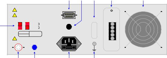
1.3.2Rear Panel Controls and Connectors
Figure 1-3 illustrates the controls and connectors on the rear panel of the Sentry Plus Series AC/DC/IR Hipot Tester. Table 1-2 identifies them with description and function.
2 |
3 |
4 |
5 |
6 |
WARNING: FOR CONTINUED PROTECTION
! AGAINST FIRE HAZARD, REPLACE ONLY WITH THE SAME TYPE AND RATING OF FUSE AS SPECIFIED FOR THE LINE VOLTAGE BEING UTILIZED.
CAUTION: NO OPERATOR SERVICEABLE PARTS ! INSIDE. REFER SERVICING TO QUALIFIED
PERSONNEL.
POLLUTION DEGREE 2 INSTALLATIONCATEGORY II
VOLTAGE SELECTOR
90V - 110V ~
1 108V - 132V ~
198V - 242V ~
216V - 250V ~
MODEL NO.
SERIAL NO.
HIGH VOLTAGE
Max 5kVAC/6kVDC
HV OUTPUT |
RTN/LOW |
1 |
5 |
6 |
9 |
3.15AT |
CONT. CHECK OPTION |
250V |
|
1.6AT
250V
100V/120V/220V/240V~ 50/60Hz 300W MAX
FAN 50o C AUTO ON/OFF
START
RESET
COM
INTER
LOCK
10 |
9 |
8 |
7 |
Figure 1-3: Rear Panel Sentry Plus Series Instrument
Table 1-2: Sentry Plus Series Rear Panel Controls & Connectors
Reference # |
Name |
Type |
Function |
Figure 1-3 |
|
|
|
1 |
VOLTAGE |
2 Red 2-position |
Select Voltage Level corresponding to AC Source |
|
SELECTOR |
Slide Switches |
90V – 110V: 3.15A 250V Slow Blow |
|
|
|
110V – 130V: 3.15A 250V Slow Blow |
|
|
|
200V – 240V: 1.6A 250V Slow Blow |
|
|
|
220V – 250V: 1.6A 250V Slow Blow |
2 |
Remote |
Silver 9-pin |
Remote Connection: Inputs: Start, Reset |
|
|
D-Type Connector |
Outputs: Pass, Fail, Under Test |
3 |
CONT CHK OPT. |
Black banana plug |
Connection for Ground Continuity Check |
4 |
TUV CE |
Sticker |
Instrument Safety Agency Listing |
5 |
Remote |
Black 5-screw |
Remote Connection: Start, Reset, Com, Interlock |
|
|
Terminal Strip |
|
6 |
Fan |
SF11580AT |
Cool Unit: T≥ 50° C = ON, T< 45° C = OFF |
|
|
115V 50/60Hz 0.10A |
|
7 |
Ground |
Silver Banana Plug |
Instrument Chassis Ground Connection |
8 |
AC Line Input |
Black 3-wire inlet |
Connection to AC power source |
|
|
module & fuse holder |
Fuse Drawer: 3.15A 250V or 1.6A 250V (see #1) |
9 |
RTN/LOW |
Blue Banana Socket |
RTN: Low voltage reference terminal |
|
|
|
LOW: Common ground reference terminal |
10 |
HV OUTPUT |
White Custom |
Rear panel High Voltage (Potential) Terminal |
|
|
Banana Socket |
|
Introduction |
Page 23 of 85 |

1.4Installation
1.4.1Dimensions
The Sentry Plus series unit is supplied in a bench configuration, i.e., in a cabinet with resilient feet for placement on a table. Flip feet are provided under the front feet so that the Sentry Plus instrument can be tilted up for convenient operator viewing.
4.50"
112.50mm
STOP |
|
|
|
|
|
|
|
F1 |
|
|
QuadTech |
Sentry 30 Plus AC/DC/IR Hipot Tester |
|
|
|||
|
|
|
|
|
||||
|
|
|
|
|
|
|
F1 |
F2 |
START |
|
|
|
|
|
|
F2 |
|
|
|
|
|
|
|
|
F3 |
|
|
|
|
|
|
|
|
F3 |
|
|
|
|
|
|
|
|
|
|
|
|
|
|
|
|
|
F4 |
F4 |
|
|
|
|
|
|
|
|
|
1 |
0 |
CAL |
UPDATE |
PASS |
FAIL |
DANGER |
RTN/LOW |
OUTPUT |
|
||||||||
CAUTION |
14.25" |
Max 5kVAC |
|
6kVDC |
|
|
356.25mm |
10.50"
262.5mm
Figure 1-4: Sentry Plus Series Instrument Dimensions
1.4.2Instrument Positioning
The Sentry Plus unit contains a graphic display for direct readout of measured parameters. The optimum angle for viewing is slightly down and about 10 degrees either side of center. For bench operation the front flip feet should always be used to angle the instrument up. In bench or rack mount applications the instrument should be positioned with consideration for ample air flow around the rear panel fan ventilation hole. An open space of at least 3 inches (75mm) is recommended behind the rear panel. Testing should be performed on a non-conductive surface. An ESD mat is not a recommended test platform.
1.4.3Power Requirements
The Sentry Plus instrument can be operated from a power source of 90 to 132V AC or 198 to 250V AC. Power connection is via the rear panel through a standard receptacle. Before connecting the 3-wire power cord between the unit and AC power source, make sure the voltage selection switches on the rear panel (Figure 1-5) are in accordance with the power source being used. For a 90-132V source, use a 3.15A 250V fuse. For a 198-250V source, use a 1.6A 250V fuse. Always use an outlet that has a properly connected protection ground.
Page 24 of 85 |
Introduction |

WARNING
MAKE SURE THE UNIT HAS BEEN DISCONNECTED FROM ITS AC POWER SOURCE
FOR AT LEAST FIVE MINUTES BEFORE PROCEEDING.
Procedure For Changing A Sentry Plus Series Fuse
Remove the fuse drawer, by pressing the black tab located at the center of the extended fuse drawer, just below the 3-prong receptacle, and pull outward.
Once the fuse drawer has been removed from the instrument slide out the fuse from the holder and replace. Make sure the new fuse is of the proper rating. Note that the fuse drawer can also be used to store a spare fuse.
Install the fuse drawer back in the inlet module by pushing in until it locks securely in place.
VOLTAGE SELECTOR |
|
100V/120V/220V/240V~ |
|
|
50/60Hz 300W MAX |
|
90V - 110V ~ |
3.15AT |
|
|
|
|
108V - 132V ~ |
250V |
|
|
|
|
198V - 242V ~ |
FUSE Drawer |
|
1.6AT |
|
|
|
|
|
216V - 250V ~ |
250V |
|
|
Figure 1-5: Close-Up of Sentry Plus Series Rear Panel
1.4.4Safety Inspection
Before operating the instrument inspect the power inlet module on the rear of the Sentry Plus to ensure that the properly rated fuse is in place, otherwise damage to the unit is possible. Make sure that the voltage selector switches are set in accordance with the power source in use. Refer to paragraph 1.4.3 and Figure 1-5.
The Sentry Plus instrument is shipped with a standard U.S. power cord, QuadTech P/N 42000300 (with Belden SPH-386 socket or equivalent, and a 3-wire plug conforming to IEC 320). Make sure the instrument is only used with these cables (or other approved international cord set) to ensure that the instrument is provided with connection to protective earth ground.
The surrounding environment should be free from excessive dust to prevent contamination of electronic circuits. The surrounding environment should also be free from excessive vibration. Do not expose the Sentry Plus instrument to direct sunlight, extreme temperature or humidity variations, or corrosive chemicals.
Introduction |
Page 25 of 85 |
 Loading...