

Page 1
Sentry Plus Series
Hipot Testers
Instruction Manual
Form 150697/A4
QuadTech, Inc., 2003
5 Clock Tower Place, 210 East
Maynard, Massachusetts, U.S.A. 01754
January 2005
Telephone: 978-461-2100
Sales: 800-253-1230
Facsimile: 978-461-4295
Website: www.quadtech.com
The material in this manual is for informational purposes only and is subject to change, without notice.
QuadTech assumes no responsibility for any error or for consequential damages that may result from the
misinterpretation of any procedures in this publication.
WARNING
Potentially dangerous voltages may be present on front and rear panel terminals. Follow all warnings in
this manual when operating or servicing this instrument. Dangerous levels of energy may be stored in
capacitive devices tested by this unit. Always make sure the high voltage indicator is not on when
connecting or disconnecting the device under test.
!
Product will be marked with this symbol (ISO#3864) when it is necessary for the user to refer to
the instruction manual in order to prevent injury or equipment damage.
Product marked with this symbol (IEC417) indicates presence of direct current.
Product will be marked with this symbol (ISO#3864) when voltages in excess of 1000V are
present.
Page 2

Page 2 of 85
Page 3

Contents
Warranty ............................................................................................................5
Specifications ............................................................................................................7
Accessories ............................................................................................................11
Safety Precautions....................................................................................................13
Condensed Operating Instructions ........................................................................15
Introduction - Section 1
1.1 Unpacking and Inspection..............................................................................21
1.2 Product Overview ..........................................................................................21
1.3 Controls and Indicators..................................................................................22
1.3.1 Front Panel Controls and Indicators .................................................22
1.3.2 Rear Panel Controls and Connectors ................................................23
1.4 Installation .....................................................................................................24
1.4.1 Dimensions ........................................................................................24
1.4.2 Instrument Positioning.......................................................................24
1.4.3 Power Requirements..........................................................................24
1.4.4 Safety Inspection................................................................................25
Operation - Section 2
2.1 Terms and Conventions.................................................................................27
2.2 Start-Up..........................................................................................................31
2.3 Programming Electrical Safety Tests.............................................................31
2.4 Programming a Ground Continuity Test .......................................................35
2.5 Programming an AC Hipot Test....................................................................37
2.6 Programming a DC Hipot Test......................................................................39
2.7 Programming an Insulation Resistance (IR) Test .........................................41
2.8 Programming a Pause (PA) in Test Sequence ..............................................43
2.9 Storing a Test Setup ......................................................................................45
2.10 Programming a Multi-Step Test.....................................................................47
2.11 PRESET Test Parameters .............................................................................48
2.11.1 AC-V FREQ ......................................................................................48
2.11.2 Software AGC ...................................................................................48
2.11.3 WV AUTO RANGE .........................................................................48
2.11.4 IR AUTO RANGE ............................................................................49
2.11.5 GFI ....................................................................................................49
2.11.6 FAIL RESTART ...............................................................................49
2.12 Instrument Offset ..........................................................................................50
2.13 Connection To Device Under Test ................................................................53
2.14 Measurement Procedure.................................................................................54
Page 3 of 85
Page 4

Contents (Continued)
2.15 MENU Parameters ........................................................................................56
2.15.1 MEMORY Function .........................................................................57
2.15.2 SYSTEM Function ............................................................................59
2.15.2.1 CONTRAST ...................................................................59
2.15.2.2 BUZZER VOLUME .......................................................59
2.15.2.3 EN 50191 ........................................................................59
2.15.2.4 DC 50V AGC ..................................................................60
2.15.3 OPTION Function .............................................................................60
2.15.4 CALIBRATION Function ................................................................60
2.15.5 KEY LOCK Function .......................................................................61
2.15.6 CHANGE PASSWORD Function ....................................................63
2.15.7 ERROR LOG Function .....................................................................65
2.15.8 ABOUT Function ..............................................................................65
Interface - Section 3
3.1 Remote ..........................................................................................................67
3.2 G16 International Power Strip.......................................................................70
3.3 S07 Power Entry Adapter Cable ...................................................................71
3.4 S03 Corded Product Adapter ........................................................................72
3.5 S05 Foot Switch ............................................................................................73
3.6 S08 Gun Probe ..............................................................................................74
3.7 S50 Plus Ground Bond Tester .......................................................................75
Service & Calibration - Section 4
4.1 General...........................................................................................................77
4.2 Instrument Return ..........................................................................................77
4.3 Calibration......................................................................................................77
4.3.1 Calibration Parameters.......................................................................78
4.3.2 Enable Calibration ............................................................................79
4.3.3 AC Voltage Calibration .....................................................................80
4.3.4 DC Voltage Calibration .....................................................................80
4.3.5 IR Voltage Calibration.......................................................................81
4.3.6 AC Current Calibration......................................................................82
4.3.7 DC Current Calibration......................................................................83
4.3.8 ARC Calibration ................................................................................84
4.3.9 IR Resistor Calibration .....................................................................84
4.3.10 Ground Continuity Calibration .........................................................85
4.3.11 Contrast Calibration ..........................................................................85
4.3.12 Finalize Calibration ...........................................................................85
Page 4 of 85
Page 5

Warranty
QuadTech warrants that Products are free from d efects in material and workmanship and, when
properly used, will perform in accordance with QuadTech’s applicable published specifications.
If within one (1) year after original shipment it is found not to meet this standard, it will be
repaired, or at the option of QuadTech, replaced at no charge when returned to a QuadTech
service facility.
Changes in the Product not approved by QuadTech shall void this warranty.
QuadTech shall not be liable for any indirect, special or consequential damages, even if
notice has been given of the possibility of such damages.
This warranty is in lieu of all other warranties, expressed or implied, including, but not
limited to any implied warranty or merchantability of fitness for a particular purpose.
SERVICE POLICY
QuadTech’s service policy is to maintain product repair capability for a period of at least five (5)
years after original shipment and to make this capability available at the then prevailing schedule
of charges.
Page 5 of 85
Page 6

Page 6 of 85
Page 7

Specifications
Dielectric Strength
Sentry 10, 20, & 30 Plus
AC Output Voltage: Range: 0.05 to 5kV AC, in 1V steps
Regulation: ± (1% of setting +5V)
Frequency: 50/60Hz selectable
Voltage Display: Accuracy: ± (1% of reading +5V)
Resolution: 1Volt
AC Current Display: Range: 0.001mA to 20mA AC, in 1µA steps
Accuracy: ± (1.5% of reading + 5 counts) (Total)
Sentry 20 & 30 Plus
DC Output Voltage: Range: 0.05 to 6kV DC, in 1V steps
Voltage Display: Accuracy: ± (1% of reading +5V)
Resolution: 1Volt
DC Current Display: Range: 0.0001mA to 5mA DC
Resolution: 0.1µA
Accuracy: ± (1.5% of reading + 5 counts)
Insulation Resistance
Sentry 30 Plus
Insulation Resistance: Voltage: 50 - 1000V DC in 1V steps
Accuracy: ± (1% of reading + 5V)
Range: 0.1MΩ - 50GΩ (voltage dependent)
Accuracy: 0.1MΩ - 1GΩ, ± (10% + 5counts) < 100V
0.1MΩ - 1GΩ, ± (7% + 5counts) < 500V
1MΩ - 1GΩ, ± (4% + 5counts) ≥ 500V
1GΩ - 10GΩ, ± (7% + 5counts) ≥ 500V
10GΩ - 50GΩ, ± (12% + 5counts) ≥ 500V
Page 7 of 85
Page 8

Specifications (Continued)
Safety Features
Ground
Continuity Test: Programmable: 0.1Ω to 5.0Ω ±0.2Ω Accuracy, or OFF
Ground Fault
Interrupt (GFI): Shutdown of current imbalance when I > 0.5mA ±0.25mA, or OFF
In-Rush Current: DC Mode: Set detection limit: 0.5uA – 5mA in 0.0001mA increments
The programmable range for In-Rush current is dependent on the
programmed High Limit:
Range: High Limit: In-Rush:
1 0.1µA – 300µA 0.5µA – 300µA
2 0.301mA – 3.000mA 5µA – 3.000mA
3 3.01mA – 5.0mA 50µA – 5.0mA
Fast Output Cutoff: HV output voltage terminated <0.4mS after NG (Fail) result
Fast Discharge: <0.2s (Typical) Discharge of DUT upon termination of HV.
ARC Detection: Detection Current: Range: 1mA – 20mA AC and 5mA DC
Pulse Width: Minimum: 10µs
General Features
Time: Test*: 0.1sec – 999 sec, Continuous
Ramp: 0.1sec – 999 sec, OFF
Dwell: 0.1sec – 999 sec, OFF (DC & IR Mode only)
Fall: 0.1sec – 999 sec, OFF
* Te st Time is limited ≤ 60seconds when the voltage and high c urrent limit > 100VA.
* Test Time for IR is 0.3sec – 999sec, Continuous
Limits: HI/LO programmable during Test Time
LO can be set to OFF during Hipot Test
HI can be set to OFF during IR Test
Indication: Pass/fail LEDs, audible alarm
Remote Control: Inputs: START, STOP
Characteristics: 24V active low, Pulse width ≅20ms
Outputs: PASS, FAIL, UNDER TEST
Characteristics: Dry contact relay, Closed if true
115V, <100mA
Connector: 9 pin male D-series & Terminal Strip
Page 8 of 85
Page 9

Specifications (Continued)
General Features
Setup Storage: 60 Memory Locations, 10 steps each
Standard
Interfaces: Remote I/O
Connectors: Front and Rear Connection
HV OUTPUT: Custom Banana Socket
RTN/LOW: Banana Socket
GC (Rear Only): Binding Post/ Banana Socket
Front Panel 10 Digit Password with or without setup recall
Lockout: LED Display: LOCK
Mechanical: Bench Mount
Dimensions:(w x h x d): 10.50 x 4.50 x 14.25 inches
262.5 x 112.5 x 356.25 mm
Weight: 25.0 lbs (11.5 kg) net, 28 lbs (13.0 kg) shipping
Environmental: Specifications: 18°C to 28°C, 70% RH
Operating: 0°C to + 40oC, 80% RH
Storage: -10°C to + 60oC, 80% RH
Warm-up Time: 15 minutes
Power:
Supplied:
Safety Agency: CE, TUV
Ordering Description Catalog No.
Information: AC Hipot Tester Sentry 10 Plus
AC/DC Hipot Tester Sentry 20 Plus
AC/DC/IR Hipot Tester Sentry 30 Plus
•
90 - 130V AC
•
200 - 250V AC
•
Instruction Manual
•
Calibration Certificate
•
Ground Continuity Lead
•
50 or 60Hz
•
300W max
•
Power Cable
•
S02 Test Leads
Page 9 of 85
Page 10

Page 10 of 85
Page 11
Accessories
Accessories Included
Item Quantity QuadTech P/N
AC Power Cord 1 4200-0300
Power Line Fuse 3.15A 250V SB 1 520072
Power Line Fuse 1.6A 250V SB 1 520074
High Voltage Lead Set, 1m with alligator clips 1 S02
Ground Continuity Lead 1 700100
Instruction Manual 1 150697
Calibration Certificate 1 N/A
Accessories/Options Available
Item Quantity QuadTech P/N
High Voltage Lead Set, high & low, 1m (std. with unit) 1 S02
Corded Product Adaptor, 115V 1 S03
High Voltage Lead Set, high & low, 2m 1 S04
Foot Switch 1 S05
High Voltage Probe 1 S06
Power Entry Adaptor Cable 1 S07
Gun Probe 1 S08
High Voltage Lead, 1m, unterminated 1 S09
High Voltage Lead, 2m, unterminated 1 S10
Gun Probe with Remote Start 1 S11
Load Box, resistive 1 S12
Load Box, custom resistors 1 S14
Interconnection Cable to Sentry 50 Ground Bond Tester 1 S15
Ground Continuity Lead (standard with unit) 1 700100
International Power Strip 1 G16
Corded Product Adaptor, 240V 1 G25
Page 11 of 85
Page 12

Page 12 of 85
Page 13

Safety Precautions
WARNING
The Sentry Plus Series Hipot Tester can provide an output voltage as high as 6000V DC (5000V
AC) to the external device under test (DUT). Although the Sentry Plus unit is designed with full
attention to operator safety, serious hazards could occur if the instrument is used improperly and
these safety instructions are not followed.
1. The Sentry Plus unit is designed for operation with its chassis connected to earth ground.
The instrument is shipped with a three-prong power cord to provide this connection to
ground. This power cord should only be plugged in to a receptacle that provides earth
ground. Serious injury can result if the Sentry Plus is not connected to earth ground.
2. Tightly connect cable(s) to the (blue) RTN/LOW terminal. If this is not done, the
DUT’s casing can be charged to the high voltage t est level and serious injur y or electri cal
shock hazards could result if the DUT is touched.
3. Never touch the metal of the High Volta ge probe directl y. Touch only the insulated parts
of the lead(s).
4. Never touch the test leads, test fixture or DUT in any manner (this includes insulation on
all wires and clips) when the high voltage is applied and the red DANGER light is ON.
5. Before turning on the Sentry Plus unit, make sure there is no device (DUT) or fixture
connected to the test leads.
6. After each test, press the [STOP] (red) button for safety if there is an y concern that HV
may still be applied to the output terminals.
7. When the red DANGER LED is lit or flashing, NEVER touch the device under test, the
lead wires or the output terminals.
8. Before touching the test lead wires or output terminals make sure:
a) The red [STOP] button has been pressed
b) The red DANGER LED is OFF.
9. In the case of an emergency, turn OFF the POWER switch using a “hot stick” and
disconnect the AC power cord from the wall. DO NOT TOUCH THE Sentry Plus
INSTRUMENT.
10. If the DANGER LED does not go off when the [STOP] button is pressed, immediately
stop using the tester. It is possible that the output voltage is still being delivered
regardless of the TEST ON/OFF control signal.
11. When the Sentry Plus instrument is used in remote control mode, be extremel y careful.
The High Voltage Output is being turned on and off with an external signal.
Page 13 of 85
Page 14

Page 14 of 85
Page 15

Condensed Operating Instructions
WARNING
High Voltage is applied to the white HV Output Terminal anytime the red DANGER LED is ON
or flashing. Always make sure the DANGER LED i s OFF when connecting or disconnecting
the device under test (DUT).
General Information
The Sentry Plus Series Hipot Tester is a measuring instrument for direct readout of hipot output
voltage and leakage current and insulation resistance. The voltage applied to the device under
test is adjustable from 50V to 5kV AC and 50V to 6kV DC. The trip current limit is
programmable from 1uA to 20mA AC in 1uA steps and from 0.1uA to 5mA DC in 0.1uA steps.
The output voltage for Insulation Resistance tests is 50V to 1000V DC over a measurement
range of 100kΩ to 50GΩ.
Start-Up
The Sentry Plus Series unit can be operated from a power source betw een 90 and 250VAC at a
power line frequency of 50 or 60Hz. The standard Sentry Plus Series unit is shipped from
QuadTech with a 3.15A fuse in place for AC 90 -130V operation. (A 1.6A fuse is included for
200-250V operation). The Sentry Plus unit is shipped with the line voltage selector set for 120V.
Refer to paragraph 1.4.3 for instructions on changing the fuse or line voltage selector.
Connect the Sentry Plus Series unit AC power cord to the source of p roper voltage. Operate the
Sentry Plus Series instrument with its chassis connected to earth ground. The Sentry Plus
instrument is shipped with a three-prong power cord to provide this connection to ground. This
power cord should only be plugged into a receptacle that provides earth ground. Serious injur y
may result if the Sentry Plus Series instrument is not connected to earth ground.
Press the [POWER] button on the front panel to apply power. To switch the powe r off, press the
[POWER] button again or if measurements are to be made proceed with the Test Parameter
Setup in Table COI-1. The Sentry Plus Series instrument should warm up for 15 minutes prior to
use.
NOTE
Please read this instruction manual in its entirety before operating this instrument.
These condensed operating instructions are not a substitute for all the information provided in the
remainder of this manual.
NOTE
Refer to paragraphs 2.3 through 2.9 for a full description of programming test parameters and
instruction on how to store the test setup. Test parameters must be set before the Sentry Plus
Series instrument can be zeroed.
Page 15 of 85
Page 16
Condensed Operating Instructions (Continued )
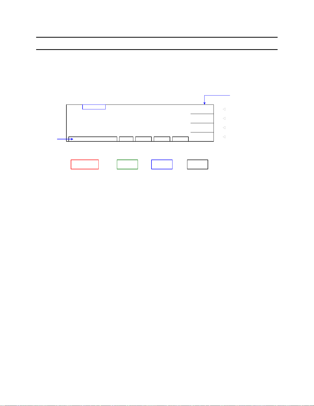
There are numerous menus within the Sentry Plus Series instruments. Familiarize yourself with
these menus prior to programming a test. Figure COI-1 illustrates the STAND BY display and
lists the functions that can be accessed by pressing the [F1] through [F4] keys.
"STAND BY" or "Power-Up" Display
Function of F1 - F4 Keys
Instrument
Status
M1
STEP 1/1
1.250kV
15.00mA
3.0s
RMT ERROFSTLOCKSTAND BY
PROGRAM MOREMENUPRESET
MORE..
Insert
Delete
NEXT
STEP: 1-10
MODE: AC/DC/IR/GC/PA
Voltage
High Limit
Test Time
Low Limit
ARC Limit
Ramp Time
Dwell Time
Fall Time
In Rush Current
(DC, IR)
(DC)
AC-V Freq. Memory
Soft AGC.
WV Auto Range
IR Auto Range
GFI
FAIL Restart
Figure COI-1: Sentry Plus Series Menus
LOWAC
ARC
RAMP
FALL
: OFF
: OFF
: OFF
: OFF
F3 F4F2F1
Recall
Delete
System
Contrast
Buzzer Volume
EN 50191
DC 50V AGC
Option
Multi-Link
Calibration
(Need password to enter)
Key Lock
(Need password to enter)
Change Password
(Need password to enter)
Error Log
About
Manufacturer
Software version
PROGRAM
PRESET
MENU
MORE..
View Test Steps (Tabular Format)
OffsetStore
To enter programming mode.
F1
To view/change preset (initial) settings.
F2
To view/change: memory, system, option,
F3
cal., key lock, pw, error & about.
To view the programmed test setups and
F4
access offset function.
Page 16 of 85
Page 17
Condensed Operating Instructions (Continued )
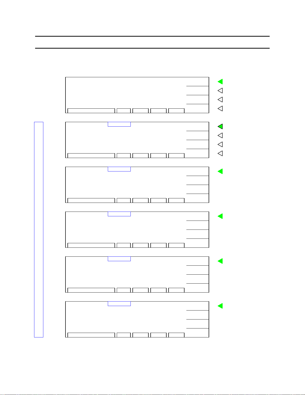
With the Sentry Plus Series instrument in “STAND BY” (or power-up display) status, follow the
steps in Table COI-1 to program an AC, DC, IR or GC test or insert a Pause in the test sequence.
"STAND BY"
DISPLAY
0.000kV
0.500mA
3.0s
LOWACSTEP 1/1
ARC
RAMP
FALL
RMT ERROFSTLOCKSTAND BY
OFF
:
OFF
:
OFF
:
OFF
:
PROGRAM
PRESET
MENU
MORE..
To enter programming mode.
F1
To view/change preset (initial)
F2
test parameters.
To view/change system parameters:
F3
memory, system, option, calibration, key
lock, password, error, & about.
To view the programmed test setups and
F4
access offset function.
PROGRAM MODE DISPLAYS
AC
Display
DC
Display
IR
Display
GC
Display
VOLT
HIGH
TIME
VOLT
HIGH
TIME
VOLT
LOW
TIME
CURR
HIGH
DWELL
0.000kV
:
0.500mA
:
3.0s
:
0.000kV
:
0.500mA
:
3.0s
:
:
0.000kV
1.0M
::3.0s
: 0.0A
:
1.0
:
3.0s
LOWACSTEP 1/1
ARC
RAMP
FALL
RMT ERROFSTLOCKSELECT MODE
LOWDCSTEP 1/1
ARC
RAMP
FALL
I-RUS
RMT ERROFSTLOCKSELECT MODE
HIGHIRSTEP 1/1
RAMP
DWELL : OFF
Ω
FALL
RMT ERROFSTLOCKSELECT MODE
GCSTEP 1/1
Ω
LOW
OFF
:
OFF
:
OFF
:
OFF
:
UP
DOWN
NEXT
EXIT
OFF
:
OFF
:
OFF
:
:
OFFDWELL
OFF
:
OFF
:
UP
DOWN
NEXT
EXIT
OFF
:
OFF
:
OFF
:
UP
DOWN
NEXT
EXIT
OFF
:
UP
DOWN
NEXT
To change value in highlighted box.
F1
To toggle choices of highlighted box.
F2
To move highlighted box around
F3
display to select parameter to change
To exit programming mode.
F4
F1
To select test mode: AC/DC/IR/GC/PA
F2
F3
F4
To select test mode: AC/DC/IR/GC/PA
F1
F2
F3
F4
F1
To select test mode: AC/DC/IR/GC/PA
F2
F3
F4
F1
To select test mode: AC/DC/IR/GC/PA
F2
F3
F4
PA
Display
PAUSE
UNDER TEST SIGNAL
PAUSE MODE
::OFF
RMT ERROFSTLOCKSELECT MODE
PASTEP 1/1
EXIT
UP
DOWN
NEXT
RMT ERROFSTLOCKSELECT MODE
EXIT
Figure COI-2: “STAND BY” and PROGRAM Displays
Page 17 of 85
Page 18
Condensed Operating Instructions (Continued )
Table COI-1: Test Parameter Setup
Step Test Para meter AC Hipot DC Hipot IR GC Range
1 To enter
programming mode
2 Select Test Step [F1] = UP
3 Select Test Mode [F1] = UP
4 Set Test Voltage
Set Current (GC)
5 Set High Limit *
Set Low Limit (IR)
6 Set Test Time
Set Dwell (GC) ***
7 Set Low Limit **
Set High Limit (IR)
8 Set ARC Limit [F1] = INC.
9 Set Ramp Time [F1] = INC.
10 Set Dwell Time*** [F1] = INC.
11 Set Fall Time [F1] = INC.
12 Set In-Rush Current [F1] = INC.
13a To program next test
step OR
13b To exit
programming mode
* High limit decision is made throughout test time.
** Unit will make low limit decision at the end of test.
* ** Limits will be checked at end of dwell time.
[F1] =
PROGRAM
[F3] = NEXT
[F3] = NEXT
[F1] = INC.
[F3] = NEXT
[F1] = INC.
[F3] = NEXT
[F1] = INC.
[F3] = NEXT
[F1] = INC.
[F3] = NEXT
[F3] = NEXT
[F3] = NEXT
[F3] = NEXT
[F1] = NEW
OR
[F4] = EXIT [F4] = EXIT [F4] = EXIT Exit programm i ng
[F1] =
PROGRAM
[F1] = UP
[F3] = NEXT
[F1] = UP
[F3] = NEXT
[F1] = INC.
[F3] = NEXT
[F1] = INC.
[F3] = NEXT
[F1] = INC.
[F3] = NEXT
[F1] = INC.
[F3] = NEXT
[F1] = INC.
[F3] = NEXT
[F1] = INC.
[F3] = NEXT
[F3] = NEXT
[F1] = INC.
[F3] = NEXT
[F3] = NEXT
[F1] = NEW
OR
[F1] =
PROGRAM
[F1] = UP
[F3] = NEXT
[F1] = UP
[F3] = NEXT
[F1] = INC.
[F3] = NEXT
[F1] = INC.
[F3] = NEXT
[F1] = INC.
[F3] = NEXT
[F1] = INC.
[F3] = NEXT
1-20mA AC
[F1] = INC.
[F3] = NEXT
[F1] = INC.
[F3] = NEXT
[F1] = INC.
[F3] = NEXT
0, 0.5uA-5mA DC
[F1] = NEW
OR
[F1] = PROGRAM
[F1] = UP
[F3] = NEXT
[F1] = UP
[F3] = NEXT
[F1] = INC.
[F3] = NEXT
[F1] = INC.
[F3] = NEXT
[F1] = INC.
[F3] = NEXT
[F1] = INC.
[F3] = NEXT
0-999s AC
0-999s DC
0-999s AC
[F1] = NEW
OR
1-10
AC, DC, IR, GC, PA
0.05-5kV AC
0.05-6kV DC
0.05-1kV IR
0.1A GC
0.001-20mA AC
0.0001-5mA DC
0.1-50000MΩ IR
0, 0.1-5Ω GC
0, 0.1-999s AC
0, 0.1-999s DC
0, 0.1-999s I R
0.1-1s GC
0-20mA AC
0-5mA DC
0-50GΩ IR
0-5Ω GC
1-5mA DC
0-999s DC
0-999s IR
0-999s IR
0-999s DC
0-999s IR
Program next step
OR
Page 18 of 85
Page 19
Condensed Operating Instructions (Continued )
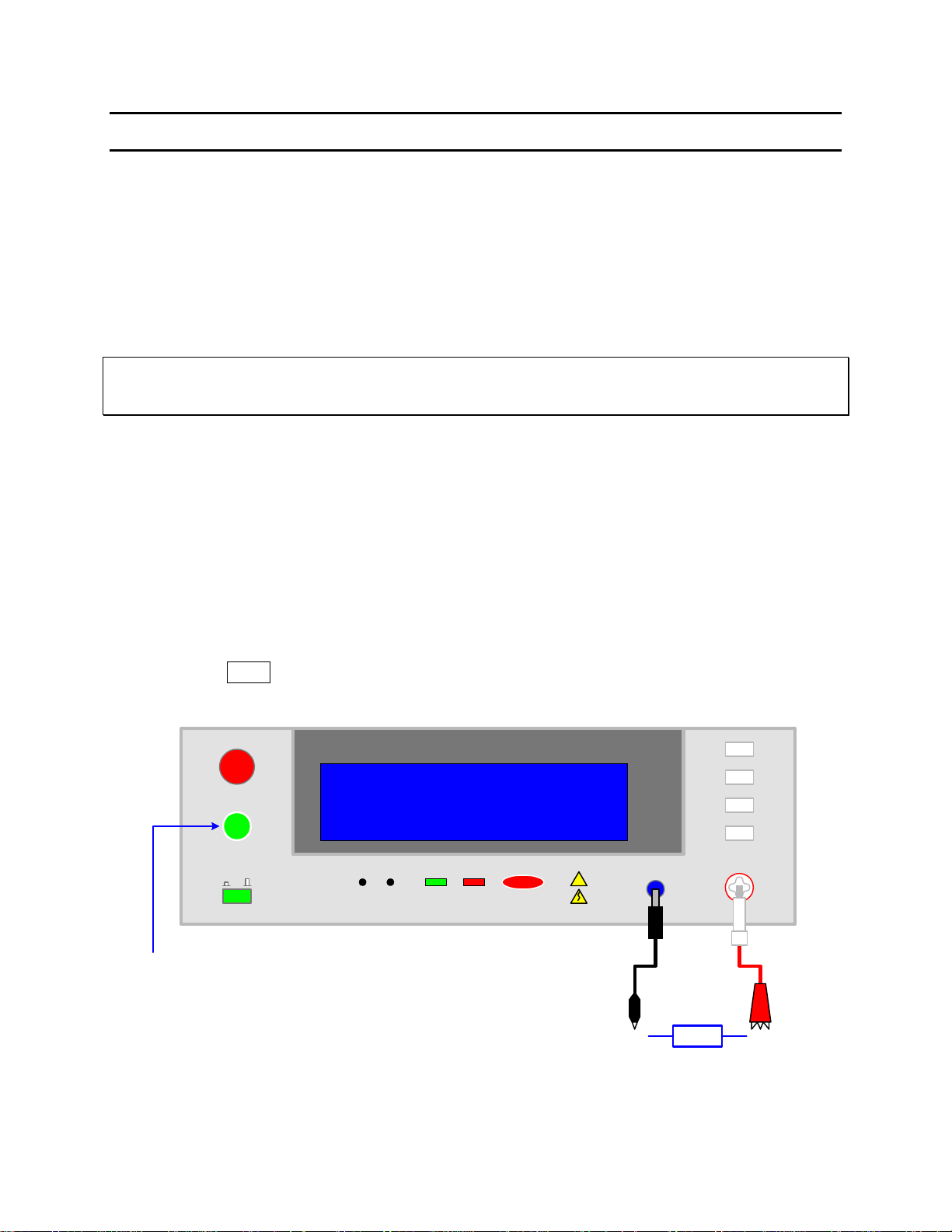
Offset
After setting your test parameters, zero the Sentry Plus Series instrument by using the automatic
offset. With no device connected, connect the appropriate cable (or other fixture) into the
OUTPUT connectors. Refer to paragraph 2.13 cable connections based on test to be performed.
Return and HV test leads should not be connected together (open circuit) for AC and DC hipot
tests. Return and GC test leads should be connected (short circuit) for a GC test. There is no
offset in an IR test.
NOTE:
If Ground Continuity (GC) is turned ON when performing an offset, the continuity lead must be connected to the
return (RTN/LOW) terminal, otherwise turn the continuity test OFF.
Prior to performing the OFFSET function:
• Allow the instrument to warm up for 15 minutes.
• Connect the Test cables (or fixture) to the front panel OUTPUT and RTN/LOW connectors.
• Program the test steps.
With the instrument in STAND BY status:
• Press [F4] = MORE
• Press [F3] = OFFSET
• Follow instructions on display: i.e.: connect OPEN across OUTPUT terminal.
• Press green [START] button.
• Wait while instrument gets OFFSET value.
• The OFST block at the bottom of the display is now highlighted (back lit).
• Press [F4] = MORE to return to STAND BY status.
STOP
START
01
When ready, press [START] to get offset values
Q
uadTech
1.
2.
Figure COI-3: Zero/Offset OPEN Configuration
Sentry 30 Plus AC/DC/IR Hipot Tester
Please open the HV output terminal
No offset in IR mode.
PRESS START KEY TO G ET OFFSET..
CAL UPDATE
DANGERPASS FAIL
!
CAUTION
Max 5kVAC
6kVDC
F1
F2
F3
F4
RTN/LOW
OPEN
F1
F2
F3
F4
OUTPUT
+-
Page 19 of 85
Page 20
Condensed Operating Instructions (Continued )
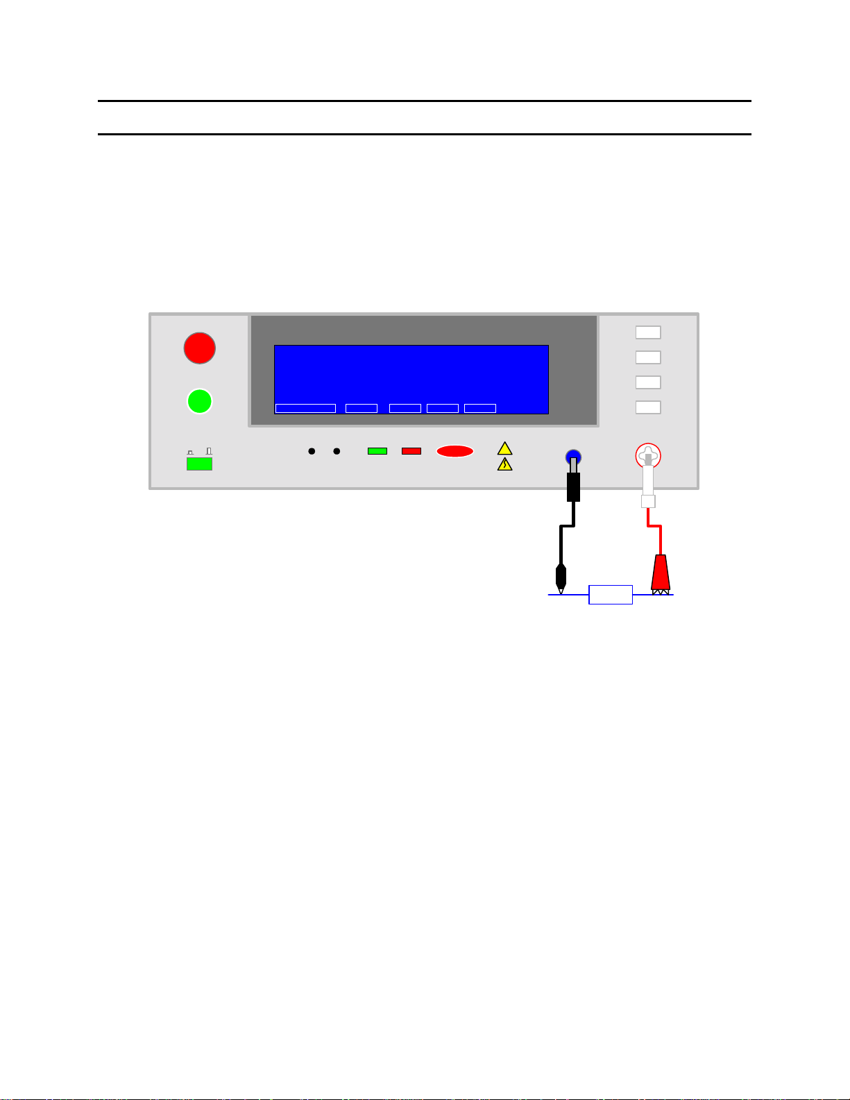
Connection to Device under Test (DUT)
Figure COI-4 illustrates the connection of the Sentry Plus Series unit to a single DUT using the
S02 1-meter HV cable set that comes standard with the instrument. The custom white banana
plug/red alligator clip is connected between the OUTPUT terminal on the Sentry Plus Series unit
and the high side of the device under test. The black banana plug/alligator clip is connected
between the RTN/LOW terminal on the Sentry Plus Series unit to the low side of the DUT.
STOP
START
Q
uadTech
M1
1.250kV
0.500mA
3.0s
STAND BY OFST
01
Sentry 30 Plus AC/DC/IR Hipot Tester
STEP 1/5
CAL UPDATE
AC
RMT LOCK ERR
LOW: OFF
ARC: OFF
RAMP: OFF
FALL: OFF
CAUTION
6kVDC
F1
F2
F3
F4
RTN/LOW
S02
Cable
Set
DUT
PROGRAM
PRESET
MENU
MORE..
DANGERPASS FAIL
!
Max 5kVAC
COI-4: Connection to Device under Test
Measurement Mode
1. Turn [POWER] ON.
Allow Sentry Plus Series instrument a 15-minute warm up time.
2.
3. Connect S02 Black ground cable to Sentry Plus Series unit RTN/LOW terminal
4. Connect S02 White/red HV cable to Sentry Plus Series unit OUTPUT terminal.
5.
Press [F1] = PROGRAM and enter test parameters. When finished programming, press
[F4] = EXIT to return to STAND BY status.
Press [F4] = MORE to access Offset function. Press [F3] = OFFSET. Follow Offset
6.
instructions. When Offset is complete, press [F4] = MORE to return to STAND BY.
7. Connect device under test (DUT) to test leads.
8.
Press [START].
9. Record measurement.
Press [STOP].
10.
F1
F2
F3
F4
OUTPUT
+-
Page 20 of 85
Page 21
Section 1: Introduction
1.1 Unpacking and Inspection
Inspect the shipping carton before opening. If damaged, contact the carrier agent immediately.
Inspect the Sentry Plus Series instrument for an y damage. If the inst rument appears dam aged or
fails to meet specifications notify QuadTech (refer to instruction manual front cover) or its local
representative. Retain t he original shipping carton and packing mat erial for future use such as
returning the instrument for recalibration or service.
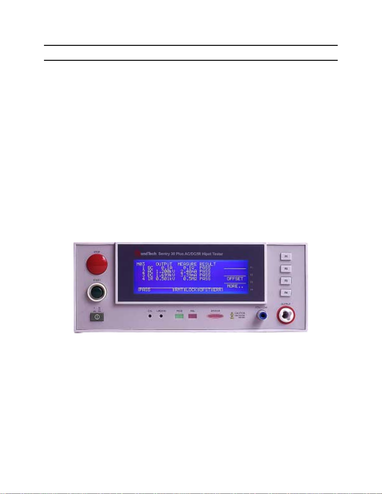
1.2 Product Overview
The Sentry Plus Series is available in three models, the 10, 20 and 30, all of which provide AC
Hipot testing capability. Additionally, the Sentry 20 & 30 Plus instruments provide DC Hipot
testing. The Sentry 30 Plus unit provides Insulation Resistance testing. The hipot test can be
programmed over a voltage range of 0.05 to 5kV AC and 0.05 to 6kV DC with a min/max
leakage current detection range of 0.001 to 20mA AC and 0.0001 to 5mA DC. Insulation
resistance measurements are possible to 50GΩ at programmable DC test voltages between 50
and 1000V. Each instrument comes standard with programmable ground continuity, internal
storage containing 60 memory locations (10 steps each) and a remote interface with start/stop
inputs & pass/fail outputs.
Figure 1-1: Sentry 30 Plus AC/DC/IR Hipot Tester
UL Requirements
The Sentry Plus Series instruments meet the requirements outlined by U L for Hipot Testers. The
Sentry Plus indicates the test potential (test voltage), has both visual and audible indication of
failure and the STOP switch must be manually pressed prior to another measurement being
made. The Sentry Plus Series instrument has a 100VA output [(5000V * 20mA) = 100VA]. The
Sentry Plus Series instrument also measures and displays the output voltage directly at the output
terminals during the test.
Introduction Page 21 of 85
Page 22
1.3 Controls and Indicators
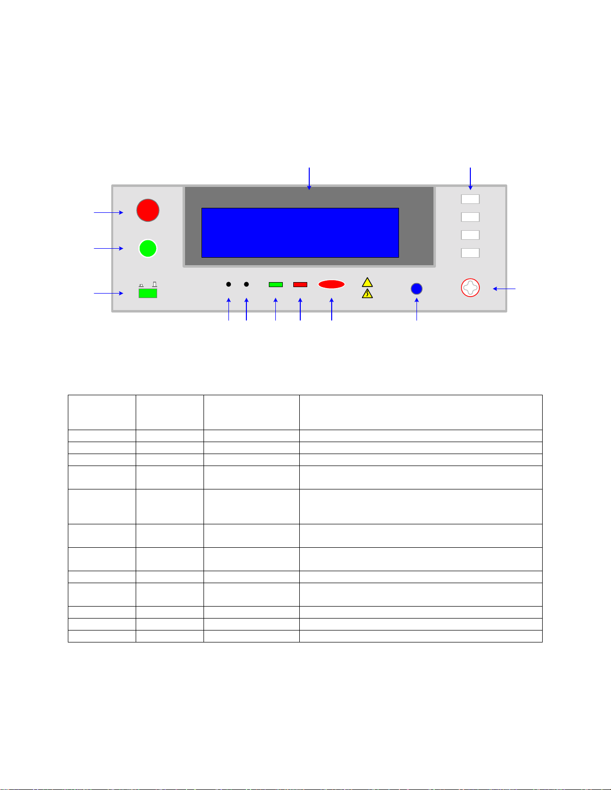
1.3.1 Front Panel Controls and Indicators
Figure 1-2 illustrates the controls and indicators on the front panel of the Sentry Plus Series
AC/DC/IR Hipot Tester. Table 1-1 identifies them with description and function.
54
STOP
Q
uadTech
3
START
2
01
1
Sentry 30 Plus AC/DC/IR Hipot Tester
CAL UPDATE
12
11 10 9
F1
F2
F3
F4
DANGERPASS FAIL
!
CAUTION
Max 5kVAC
8
RTN/LOW
6kVDC
7
F1
F2
F3
F4
OUTPUT
Figure 1-2: Sentry 30 Plus Front Panel Controls & Indicators
Table 1-1: Sentry 30 Plus Front Panel Controls & Indicators
Reference
Number
Figure 1-2
1 Power Green Push Button Apply AC Power: 1=ON, 0=OFF
2 START Green Push Button Initiate Test: HV applied to OUTPUT terminal
3 STOP Red Push Button Stop Test: HV terminated at OUTPUT terminal
4 Display LCD Pro gram Menu, Test Setup, Measurement Results,
5 F1, F2, F3
6 OUTPUT White Custom
7 RTN/LOW Blue Banana Socket RTN: Low voltage reference terminal
8 DANGER Red LED When lit, high voltage is present at OUTPUT terminals
9 FAIL Red LED When lit, DUT judged as FAIL. Output voltage is
10 PASS Green LED When lit, DUT judged as PASS
11 UPDATE Recessed P-B Qualified Service Personnel Only
12 CAL Recessed P-B Enable/Disable Instrument Calibration
Name Type Function
Memory Contents, Calibration
Gray Push Buttons Select Instru men t Functions
and F4
Keys perform different functions under different menus.
Right side of display shows corresponding key function.
High Voltage (Potential) Terminal
Banana Socket
LOW: Common ground reference terminal
immediately cut off. Press [STOP] to disable FAIL LED
6
Page 22 of 85 Introduction
Page 23
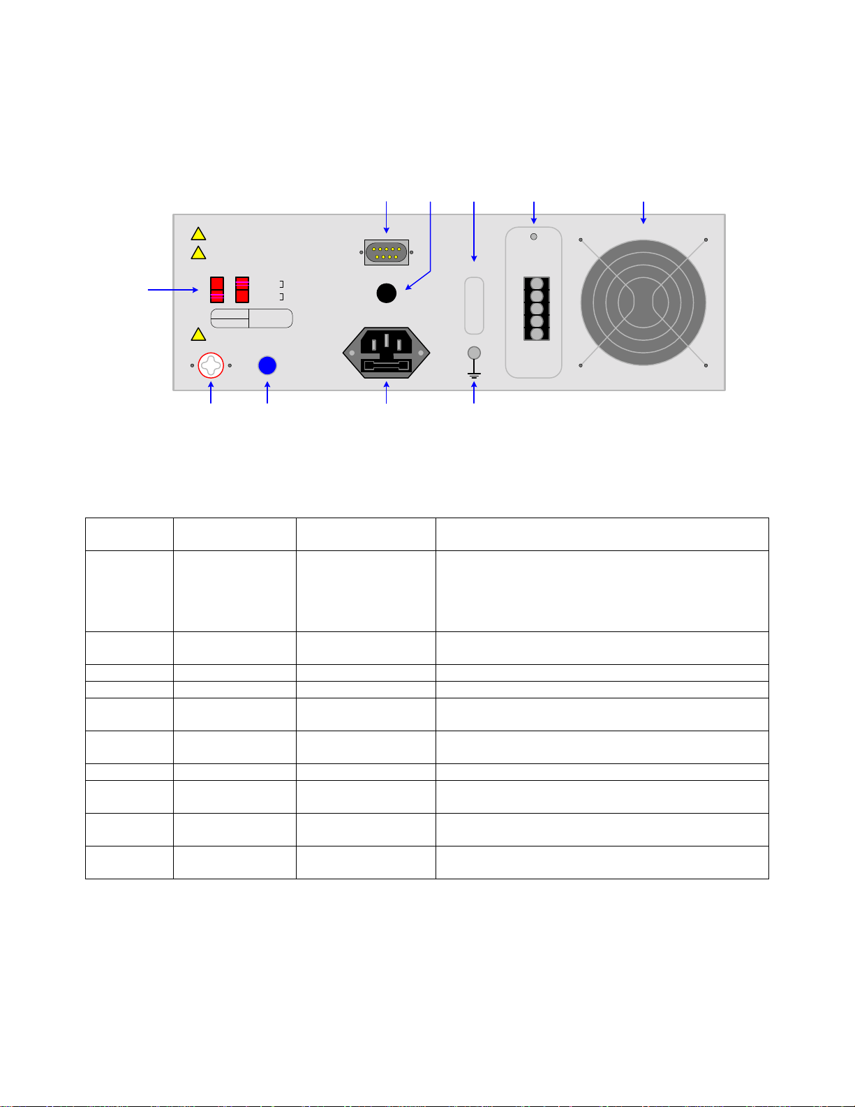
1.3.2 Rear Panel Controls and Connectors
Figure 1-3 illustrates the controls and connectors on the rear panel of the Sentry Plus Series
AC/DC/IR Hipot Tester. Table 1-2 identifies them with description and function.
3254
WARNING: FOR CONTINUED PROTECTION
AGAINST FIRE HAZARD, REPLACE ONLY WITH
THE SAME TYPE AND RATING OF FUSE AS
!
SPECIFIED FOR THE LINE VOLTAGE BEING
UTILIZED.
CAUTION: NO O PERATOR SERVICEABLE PARTS
INSIDE. REFER SERVICING TO QUALIFIED
!
PERSONNEL.
POLLUTION DEGREE 2
INSTALL ATION CATEGORY II
VOLTAGE SELECTOR
1
MODEL NO.
SERIAL NO.
HIGH VOLTAGE
Max 5kVAC/6kVDC
HV OUTPUT
90V - 110V ~
108V - 132V ~
198V - 242V ~
216V - 250V ~
RTN/LOW
3.15AT
250V
1.6AT
250V
15
69
CONT. CHECK OPTION
100V/120V/220V/240V~
50/60Hz 300W MAX
START
RESET
COM
INTER
LOCK
6
FAN 50o C AUTO ON/OFF
10 9
78
Figure 1-3: Rear Panel Sentry Plus Series Instrument
Table 1-2: Sentry Plus Series Rear Panel Controls & Connectors
Reference #
Figure 1-3
1 VOLTAGE
2 Remote Silver 9-pin
3 CONT CHK OPT. Black banana plug Connection for Ground Continuity Check
4 TUV CE Sticker Instrument Safety Agency Listing
5 Remote Black 5-screw
6 Fan SF11580AT
7 Ground Silver Banana Plug Instrument Chassis Ground Connection
8 AC Line Input Black 3-wire inlet
9 RTN/LOW Blue Banana Socket RTN: Low voltage reference terminal
10 HV OUTPUT White Custom
Name Type Function
SELECTOR
2 Red 2-position
Slide Switches
Select Voltage Level corresponding to AC Source
90V – 110V: 3.15A 250V Slow Blow
110V – 130V: 3.15A 250V Slow Blow
200V – 240V: 1.6A 250V Slow Blow
220V – 250V: 1.6A 250V Slow Blow
Remote Connection: Inputs: Start, Reset
D-Type Connector
Outputs: Pass, Fail, Und e r Test
Remote Connection: Start, Reset, Com, Interlock
Terminal Strip
Cool Unit: T≥50°C = ON, T<45°C = OFF
115V 50/60Hz 0.10A
Connection to AC power source
module & fuse holder
Fuse Drawer: 3.15A 250V or 1.6A 250V (see #1)
LOW: Common ground reference terminal
Rear panel High Voltage (Potential) Terminal
Banana Socket
Introduction Page 23 of 85
Page 24
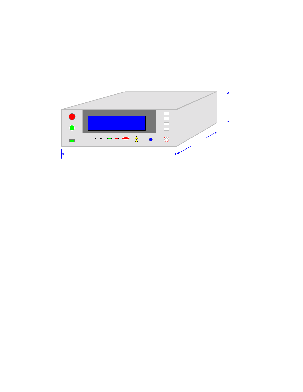
1.4 Installation
1.4.1 Dimensions
The Sentry Plus series unit is supplied in a bench configuration, i.e., in a cabinet with resilient
feet for placement on a table. Flip feet are provided under the front f eet so that the Sentry Plus
instrument can be tilted up for convenient operator viewing.
4.50"
STOP
START
01
Sentry 30 Plus AC/DC/IR Hipot Tester
QuadTech
CAL UPDATE
10.50"
262.5mm
F1
F2
F3
F4
DANGERPASS FAIL
CAUTION
Max 5kVAC
RTN/LOW
6kVDC
F1
F2
F3
F4
OUTPUT
14.25"
356.25mm
112.50mm
Figure 1-4: Sentry Plus Series Instrument Dimensions
1.4.2 Instrument Positioning
The Sentry Plus unit contains a graphic display for direct readout of measured parameters. The
optimum angle for viewing is slightly down and about 10 degrees either side of center. For
bench operation the front flip feet should always be used to angle the instrument up. In bench or
rack mount applications the instrument should be positioned with consideration for ample air
flow around the rear panel fan ventilation hole. An open space of at least 3 inches (75mm) is
recommended behind the rear panel. Testing should be performed on a non-conductive surface.
An ESD mat is not a recommended test platform.
1.4.3 Power Requirements
The Sentry Plus instrument can be operated from a power source of 90 to 132V AC or 198 to
250V AC. Power connection is via the rear panel through a standard receptacle. Before
connecting the 3-wire power cord between the unit and AC power sour ce, make sure the voltage
selection switches on the rear panel (Fi gure 1-5) are in accordance with the power sour ce being
used. For a 90-132V source, use a 3.15A 250V fuse. For a 198-250V so urce, use a 1.6A 250V
fuse. Always use an outlet that has a properly connected protection ground.
Page 24 of 85 Introduction
Page 25
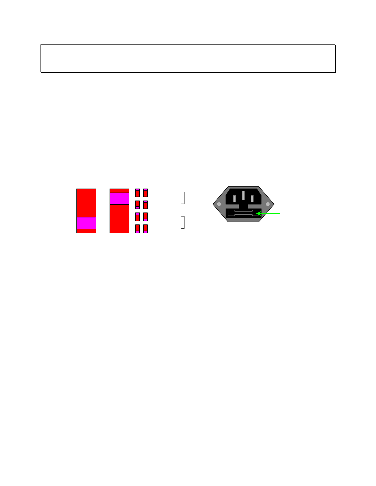
WARNING
MAKE SURE THE UNIT HAS BEEN DISCONNECTED FROM ITS AC POWER SOURCE
FOR AT LEAST FIVE MINUTES BEFORE PROCEEDING.
Procedure For Changing A Sentry Plus Series Fuse
Remove the fuse drawer, by pressing the black tab located at the center of the extended
fuse drawer, just below the 3-prong receptacle, and pull outward.
Once the fuse drawer has been removed from the instrument slide out the fuse from the holder
and replace. Make sure the new fuse is of the proper rating. Note that the fuse drawer can also
be used to store a spare fuse.
Install the fuse drawer back in the inlet module by pushing in until it locks securely in place.
VOLTAGE SELECTOR
90V - 110V ~
108V - 132V ~
198V - 242V ~
216V - 250V ~
3.15AT
250V
1.6AT
250V
100V/120V/220V/240V~
50/60Hz 300W MAX
FUSE Drawer
Figure 1-5: Close-Up of Sentry Plus Series Rear Panel
1.4.4 Safety Inspection
Before operating the instrument inspect the power inlet module on the rear of the Sentry Plus to
ensure that the properly rated fuse i s in place, otherwise damage to the unit is possible. M ake
sure that the voltage selector swit ches are set in accordance with the power source in use. R efer
to paragraph 1.4.3 and Figure 1-5.
The Sentry Plus instrument is shipped with a standard U.S. power cord, QuadTech P/N 42000300 (with Belden SPH-386 socket or equivalent, and a 3-wire plug conforming to IEC 320).
Make sure the instrument is only used with these cables (or other approved international cord
set) to ensure that the instrument is provided with connection to protective earth ground.
The surrounding environment should be free from excessive dust to prevent contamination of
electronic circuits. The surrounding environment should also be free from excessive vibration.
Do not expose the Sentry Plus instrument to direct sunlight, extreme temperature or humidity
variations, or corrosive chemicals.
Introduction Page 25 of 85
Page 26

Page 27

Section 2: Operation
2.1 Terms and Conventions
Table 2-1: Measurement Unit Prefixes
Multiple Scientific Engineering Symbol
1000000000000000 1015 Peta P
1000000000000 1012 Tera T
1000000000 109 Giga G
1000000 106 Mega M
1000 103 Kilo k
.001 10-3 milli m
.000001 10-6 micro u
.000000001 10-9 nano n
.000000000001 10
.000000000000001 10
ARCing: Sparking or ‘flashing over’ caused by a breakdown of electrical
Current:
AC: Alternating Current. AC is an electrical current that has one
DC: Direct Current. Non-reversing polarity. The movement of charge
Charging Current: An insulated product exhibits the basic characteristics of a
-12
pico p
-15
insulation.
polarity during part of the cycle and the opposing polarity during
the other part of the cycle. Residential electricity is AC.
is in one direction. Used to describe both current and voltage.
Batteries supply direct current (DC).
capacitor. Application of a voltage across the insulation causes a
current to flow as the capacitor charges. This current
instantaneously rises to a high value as voltage is applied then
exponentially decays to zero as the DUT becomes fully charged.
Charging current decays to zero much faster than dielectric
absorption.
femto f
Operation Page 27 of 85
Page 28

Dielectric Absorption: The physical phenomenon in which insulation appears to absorb
and retain an electrical c harge slowly over time. Apply a voltage
to a capacitor for an extended period of time. Then quickly
discharge it to zero voltage. Leave the capacitor open circuited
for a period of time then connect a voltmeter to it and measure the
residual voltage. The residual voltage is caused by the dielectric
absorption of the capacitor.
Dielectric Strength: The ratio between the voltage at which breakdown of the insulating
material occurs and the distance between the two poi nts subject to
the applied voltage.
Dielectric Withstand Test: This is t he most common electrical safety test perform ed. A high
voltage (either AC or DC) is applied to determine if a breakdown
will occur in the insulation of the DUT. Dielectric Withstand is
also referred to as a hipot (high potential) test.
Discharge: The act of draining off an electrical charge to gro und. Devices that
retain charge should be discharged after an IR test or DC hipot test.
DUT: Device Under Test. (i.e. the product being tested).
Frequency: The rate at which current or voltage reverses polarity and then
back again completing a full cycle, measured in Hertz (Hz) or
cycles/second. AC Line Frequency = 50/60 Hz.
Ground:
Ground: The base reference from which voltages are measured, nominall y
the same potential as the earth. Ground is also the side of a circuit
that is at the same potential as the base reference.
Ground Bond Test: Test to verify that all conductive parts of a product that are
exposed to user contact are connected to the power line ground.
The ground bond test verifies the integrity of the ground
connection using a high current AC signal with current level as
high as 30Amps. Ground bond provides a better simulation of how
a product will perform under an actual fault condition.
Ground Continuity: Test to verify that all conductive parts of a product that are
exposed to user contact are connected to the power line ground.
GC Test normally performed with a low current DC signal that
checks to ensure the ground connection has a resistance of <1Ω.
Page 28 of 85 Operation
Page 29

Insulation Resistance: Measures the total resistance between any two points separated by
electrical insulation. The IR test determines how effective the
dielectric (insulation) is in resisting the flow of electrical current.
Interface:
IEEE-488: General Purpose Interface Bus (GPIB). GPIB is an industry
standard definition of a Parallel bus connection for the purpose of
communicating data between devices.
RS232: An industry standard definition for a Serial line communication
link or port.
Scanner: An electronic device designed to switch or matrix signals.
Leakage Current (LC):
Leakage Current: The residual flow of current that flows through the insulation after
a high voltage has been applied for a period of time. The leaka ge
current is equal to the applied voltage divided by the insulation
resistance. Leakage current is the main measured value for AC
hipot and DC hipot.
Applied Part LC Test: A line leakage current test that measures the current that would
flow from, to or between applied parts such as sensor and patient
leads. This test is the most complicated and time-consuming line
leakage test.
Earth LC Test: The most important and most common of the line leakage tests.
Earth leakage current is basically the current flowing back through
the ground conductor on the power cord. It is measured by
opening the ground conductor, inserting a circuit with the
simulated impedance of the human body then measuring the
voltage across part of the circuit with a true RMS voltmeter.
Enclosure LC Test: A line leakage test that measures t he cu rrent t hat flows throu gh the
human body if the body had touched the enclosure of the DUT.
Line LC Test: A line voltage leakage current test simulates the effect of a person
touching exposed metal parts of a product and detects whether or
not the leakage current that flows through the person’s body
remains below a safe level. Apply power to the product being
tested, then measure the leakage current from any exposed metal
on the chassis of the product under a fault condit ions such as “no
ground”. A special circuit is used to simulate the impedance of the
human body.
Operation Page 29 of 85
Page 30
Limits:
High Limit: The upper value for a test to be conside red a pass. If the measured
value is higher than the high limit the test is considered a fail. In
hipot, leakage current and ground bond test modes a high limit is
required.
Low Limit: The lower value for a test to be considered a pass. If the measured
value is lower than the low limit the test is considered a fail. In
insulation resistance test mode a low limit is required. In an AC or
DC Hipot test, the low limit FAIL decision occurs at the end of the
programmed test time.
Mode: The test to be performed such as: AC Hipot (AC), DC Hipot (DC),
Insulation Resistance (IR), Ground Continuity (GC) or Pause (PA).
Step: The order in which the tests will be performed. For example if
step 1 is a ground continuity test, step 2 an AC hipot and step 3 an
insulation resistance measurement then when the START but ton is
pressed, the Sentry will perform a GC test followed by an AC test
then an IR test.
Test Time:
Ramp: The period of time for the voltage to climb to programmed level.
Dwell: The period of time for the voltage to settle at programmed level.
Test: The period of time that the voltage is applied to the DUT.
Fall: The period of time for the voltage to decrease back to 0.
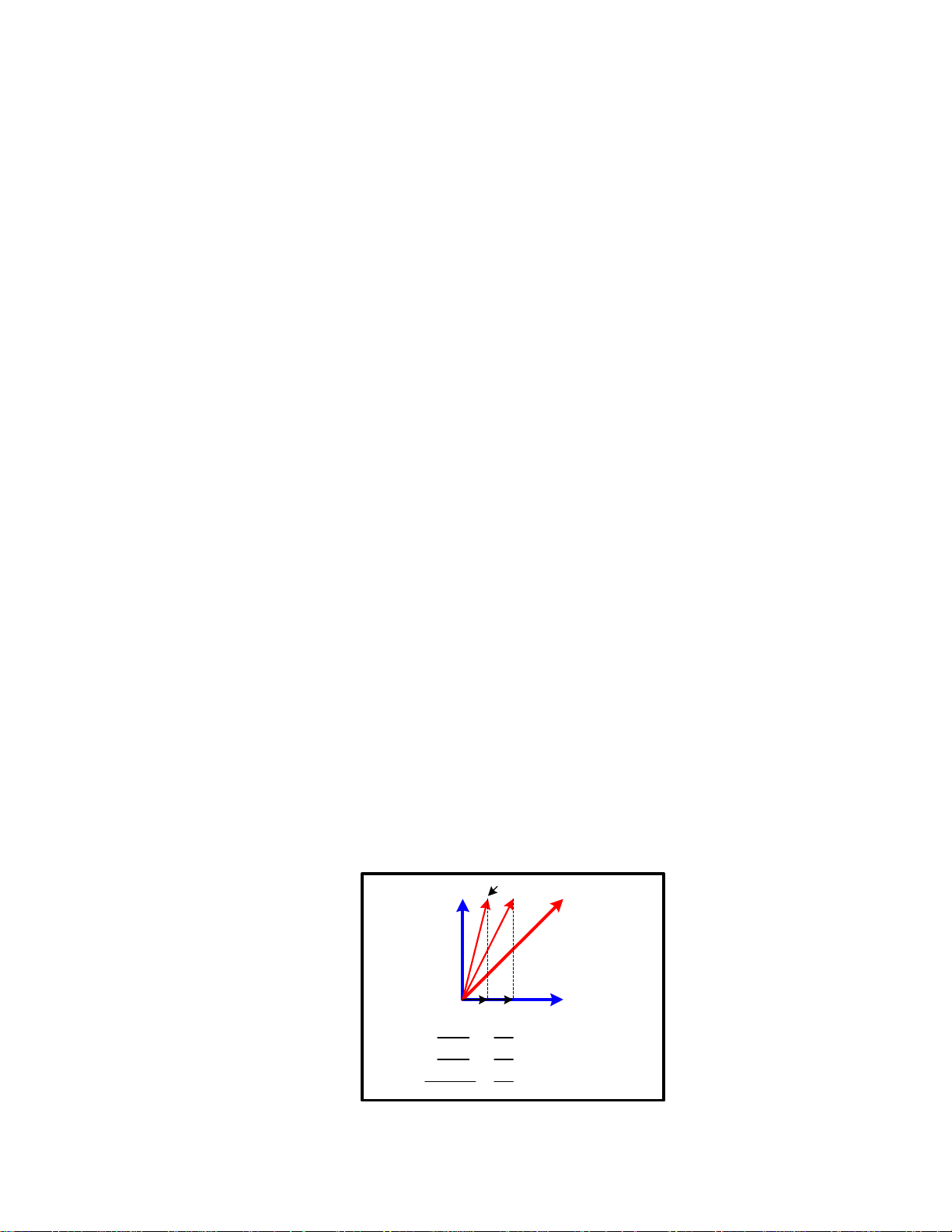
Test Current:
Real Current: The resistive current component of the device under test. The
resistive component is attributed to the resistance of the device’s
insulation.
Total Current: A measure of the resistive and reactive current components of the
device under test. The reactive component is attributed to the
capacitive or inductive components of the circuit
Total Current "A"
"A" "B"
=
=
=
Total Current "B"
200
> 100% Change
100
101
> 1% Change
100
100
>
100
Total Current
Real
(Resistive)
Current
Component
0% Change
Reactive
(Capacitive)
Current
Component
Real "B"
Real "A"
Total "B"
Total "A"
Reactive "B"
Reactive "A"
Page 30 of 85 Operation
Page 31
2.2 Startup
Check to make sure the Red Voltage Selector Switches on the rear panel agree with the power
source available. Depending on the power source the switch positions should be in the up or
down positions as shown in Figure 1-5 (Close-Up of Sentry Plus Series Rear Panel).
WARNING
NEVER TOUCH THE TEST LEADS IN ANY MANNER (this includes insulation on all wires and clips) when
HIGH VOLTAGE IS APPLIED and red DANGER LED is ON.
USE ALL PRECAUTIONS NECESSARY TO AVOID TOUCHING THE DEVICE UNDER TEST WH EN THE
RED DANGER LED IS ON OR FLASHING.
Connect the instrument power cord to the source of proper voltage. The instrumen t is to be
used only with three-wire grounded outlets.
Power is applied to the Sentry Plus Series instrument by pressing the green [POW ER] switch on
the front panel to the ON (1 position). The Sentr y Plus Series unit should warm up for a period
of at least 15 minutes prior to use.
WARNING
DO NOT TURN INSTRUMENT POWER ON OR OFF WITH TEST DEVICES CONNECTED.
2.3 Programming Electrical Safety Tests
The Sentry Plus Series instrument is capable of performing the tests listed in Table 2-2. A
single-step test can be performed on a device and is programmed as described in paragraphs 2.4
– 2.8. When the device under test requires a multi-step test the order of test precedence is
important. Refer to paragraph 2.9 for test setup store/re call instructions and to paragraph 2.10 fo r
instructions on programming a multi-step test.
Table 2-2: Sentry Plus Series Electrical Safety Tests
Test Software
Designation
Programming
Instructions
Sentry Plus Series
Instrument
Paragraph
Ground Continuity GC 2.4 10, 20, 30
AC Hipot AC 2.5 10, 20, 30
DC Hipot DC 2.6 20, 30
Insulation Resistance IR 2.7 30
Pause PA 2.8 10, 20, 30
Storing a Test Setup 2.9 10, 20, 30
Multi-Step 2.10 10, 20, 30
NOTE:
This manual is set up so if you follow the instructions in paragraphs 2.4 through 2.9 and you will
have programmed a 5-step test setup and stored it to memory location 1.
Operation Page 31 of 85
Page 32

Function keys of the STAND BY Display
The function keys on the right hand side of the displa y allow the operator to access the numerous
menus imbedded within the Sentry Plus Series instrument software. Familiarize yourself with
these menus prior to programming a test. Figure 2-1 illustrates the STAND BY display and lists
the functions that can be accessed by pressing the [F1] through [F4] keys.
"STAND BY" or "Power-Up" Display
Function of F1 - F4 Keys
Instrument
Status
M1
STEP 1/1
1.250kV
15.00mA
3.0s
RMT ERROFSTLOCKSTAND BY
PROGRAM MOREMENUPRESET
MORE..
Insert
Delete
NEXT
STEP: 1-10
MODE: AC/DC/IR/GC/PA
Voltage
High Limit
Test Time
Low Limit
ARC Limit
Ramp Time
Dwell Time
Fall Time
In Rush Current
(DC, IR)
(DC)
AC-V Freq. Memory
Soft AGC.
WV Auto Range
IR Auto Range
GFI
FAIL Restart
Figure 2-1: STAND BY Function Key Menus
LOWAC
ARC
RAMP
FALL
: OFF
: OFF
: OFF
: OFF
F3 F4F2F1
Recall
Delete
System
Contrast
Buzzer Volume
EN 50191
DC 50V AGC
Option
Multi-Link
Calibration
(Need password to enter)
Key Lock
(Need password to enter)
Change Password
(Need password to enter)
Error Log
About
Manufacturer
Software version
PROGRAM
PRESET
MENU
MORE..
View Test Steps (Tabular Format)
OffsetStore
To enter programming mode.
F1
To view/change preset (initial) settings.
F2
To view/change: memory, system, option,
F3
cal., key lock, pw, error & about.
To view the programmed test setups and
F4
access offset function.
Page 32 of 85 Operation
Page 33

POWER UP and STAND BY Displays
The Sentry Plus Series instruments have multiple menus or displays that may seem confusing at
first glance. In an attempt to clarify the numerous functions of the software, this instruction
manual will illustrate these displays in a (hopefully) logical format. The function keys (F1, F2,
F3 & F4) perform different tasks depending upon the menu currently shown on the display.
Figure 2-2 illustrates the instrument display when the instrument is initially turned on.
Function of F1 - F4 KeysSoftware
F1
F2
F3
EXIT
F4
Memory
Calibration
Line Frequency
Model #
SENTRY PLUS 30 VERSION X.XX
DATA MEMORY CHECK
CALIBRATION DATA
AC LINE FREQUENCY
:
:
:
RMT ERROFSTLOCKWAIT 3s
PASS
PASS
60 Hz
Power Up Display: Instrument Initialization
Figure 2-2: Power-Up Display
After 3 seconds, the instrument display reverts to the STAND BY display as illustrated in Figure
2-3. The box in the lower left hand corner denotes the instrument status.
Test Voltage (kV)
Test Current (mA)
Test Time (sec)
Memory
Location Mx
x = 1-60
M1
1.250kV
15.00mA
Test Step 1/x
3.0s
x = 1-10
STEP 1/1
Test Mode
AC, DC, IR,
GC or PA
RMT ERROFSTLOCKSTAND BY
Test
Settings
LOW : OFFAC
ARC : OFF
RAMP: OFF
FALL: OFF
Function
of
F1 - F4 Keys
PROGRAM
PRESET
MENU
MORE..
To enter programming mode.
F1
To view/change preset (initial)
F2
test parameters.
To view/change system parameters:
memory, system, option, calibration, key
F3
lock, password, error, & about.
To view the programmed test setups and
F4
access offset function.
Instrument Status
STAND BY
When box is highlighted (back lit),
the function is
ON.
Remote
Status
On/Off
Front
Panel
Lock Out
Status
On/Off
Offset
Status
On/Off
Error
Status
On/Off
Figure 2-3: STAND BY Display
To access the programming function of the Sentry Plus Series instrument in the STAND BY
menu, press the [F1] key (PROGRAM). Once in the PROGRAM di splay, select the test step
then the test mode (AC, DC, IR, GC or PA). Paragraphs 2.4 - 2.8 illustrate how to program the
specific parameters of each of the 5 tests.
NOTE
This manual is set up so if you follow the instructions in paragraphs 2.4-2.9 you will have programmed a 5-step test
(GC, AC, DC, IR and PA) and saved to memory location 1.
Operation Page 33 of 85
Page 34
PROGRAM Mode Displays
Figure 2-4 illustrates each program mode display for quick reference. The box in the lower left
hand corner denotes the instrument status. For clarity, a green arrow (!) is used to denote
which function key (F1 – F4) is pressed to get to the next display screen.
"STAND BY"
DISPLAY
AC
Display
DC
Display
IR
Display
0.000kV
0.500mA
3.0s
VOLT
:
HIGH
:
TIME
:
VOLT
:
HIGH
:
TIME
:
VOLT
:
LOW
TIME
::3.0s
0.000kV
0.500mA
3.0s
0.000kV
0.500mA
3.0s
0.000kV
1.0M
Ω
LOWACSTEP 1/1
ARC
RAMP
FALL
RMT ERROFSTLOCKSTAND BY
LOWACSTEP 1/1
ARC
RAMP
FALL
RMT ERROFSTLOCKSELECT MODE
LOWDCSTEP 1/1
ARC
RAMP
FALL
I-RUS
RMT ERROFSTLOCKSELECT MODE
HIGHIRSTEP 1/1
RAMP
DWELL : OFF
FALL
OFF
:
OFF
:
OFF
:
OFF
:
PROGRAM
PRESET
MENU
MORE..
OFF
:
OFF
:
OFF
:
OFF
:
UP
DOWN
NEXT
EXIT
OFF
:
OFF
:
OFF
:
:
OFFDWELL
OFF
:
OFF
:
UP
DOWN
NEXT
EXIT
OFF
:
OFF
:
OFF
:
UP
DOWN
NEXT
To enter programming mode.
F1
To view/change preset (initial)
F2
test parameters.
To view/change system parameters:
F3
memory, system, option, calibration, key
lock, password, error, & about.
To view the programmed test setups and
F4
access offset function.
To change value in highlighted box.
F1
To toggle choices of highlighted box.
F2
To move highlighted box around
F3
display to select parameter to change
To exit programming mode.
F4
F1
To select test mode: AC/DC/IR/GC/PA
F2
F3
F4
To select test mode: AC/DC/IR/GC/PA
F1
F2
F3
F4
F1
To select test mode: AC/DC/IR/GC/PA
F2
F3
F4
F1
To select test mode: AC/DC/IR/GC/PA
F2
F3
F4
PROGRAM MODE DISPLAYS
GC
Display
PA
Display
CURR
: 0.0A
HIGH
DWELL
PAUSE
UNDER TEST SIGNAL
Ω
:
1.0
:
3.0s
PAUSE MODE
::OFF
RMT ERROFSTLOCKSELECT MODE
GCSTEP 1/1
LOW
OFF
:
EXIT
UP
DOWN
NEXT
RMT ERROFSTLOCKSELECT MODE
PASTEP 1/1
EXIT
UP
DOWN
NEXT
RMT ERROFSTLOCKSELECT MODE
EXIT
Figure 2-4: STAND BY & PROGRAM Mode Displays
Page 34 of 85 Operation
Page 35
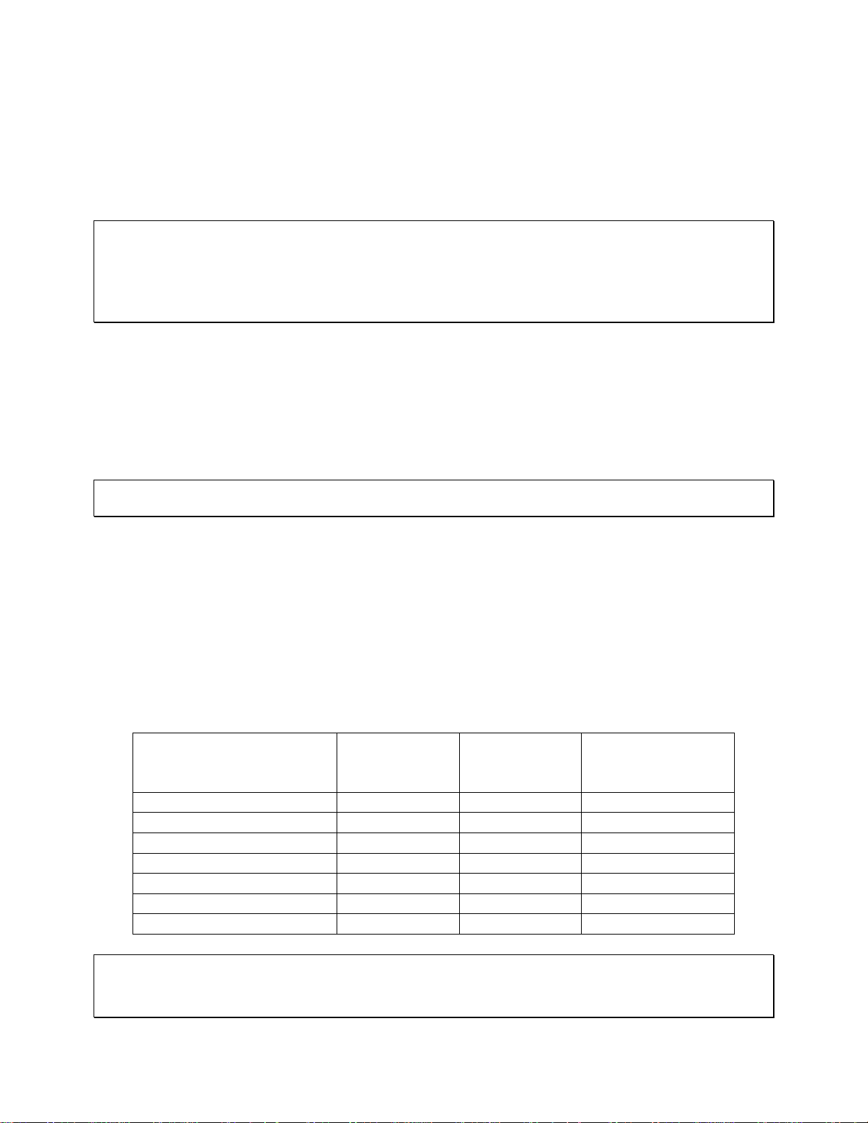
2.4 Programming a Ground Continuity Test
This test is applicable to the Sentry 10, 20 and 30 Plus instruments. A Ground Continuity (GC)
test is usually done first to verify the ground connection before high voltage is applied in the AC
& DC Hipot tests. With the instrument in ‘stand-by’ status, press [F1] = PROGRAM. The AC
test mode programming screen is displayed. Follow the green arrows (!) on the right side of
this diagram to program the individual GC test parameters.
VOLT:
In STAND BY:
Press [F1] =
PROGRAM
Select
GC
Mode
Set
Current
Set
HIGH
Resistance Limit
HIGH:
TIME:
CURR:
HIGH:
DWELL:
CURR:
HIGH:
DWELL:
CURR:
HIGH:
DWELL:
0.000 kV
0.500 mA
Ω
Continue on Next Page.
3.0 s
0.0 A
1.0
0.3 s
0.0A
1.0
0.3s
0.1A
1.0
0.3s
1/1
LOWACSTEP:
ARC
RAMP
FALL
RMT ERROFSTLOCKVoltage is 0
LOWGCSTEP 1/1
Ω
RMT ERROFSTLOCKSelect Mode
LOWGCSTEP 1/1
Ω
RMT ERROFSTLOCK0.1A
LOWGCSTEP 1/1
Ω
RMT ERROFSTLOCK0.1 - 5
OFF
:
OFF
:
OFF
:
OFF
:
MORE..
NEXT
EXIT
OFF
:
UP
DOWN
NEXT
EXIT
OFF
:
INC.
DEC.
NEXT
EXIT
OFF
:
INC.
DEC.
NEXT
EXIT
F1
F2
To move highlighted box to AC.
F3
F4
F1
To select Mode = GC
F2
F3
To move highlighted box to CURR.
F4
F1
To set current to 0.1A
F2
F3
To move highlighted box to HIGH.
F4
To set High resistance limit:
F1
0.1 - 5Ω in 0.1Ω increments.
F2
To move highlighted box to DWELL.
F3
F4
Operation Page 35 of 85
Page 36

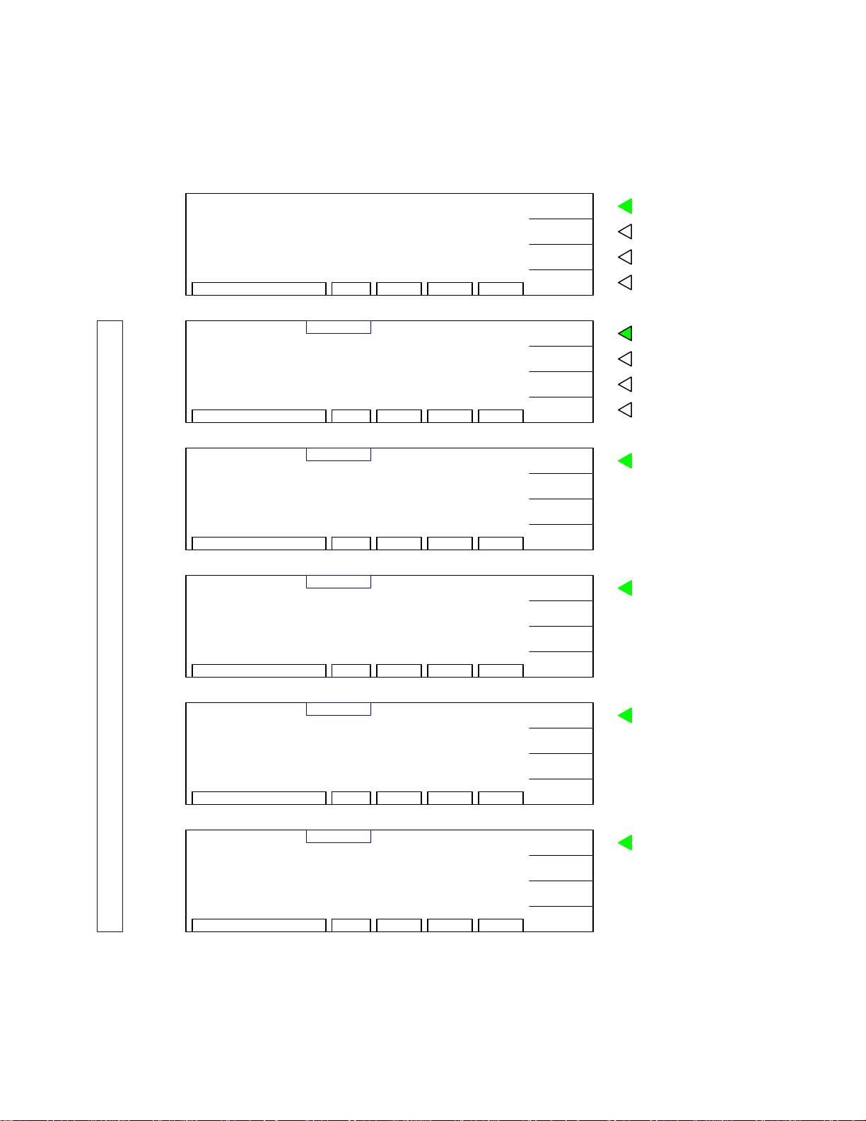
Programming a GC Test (continued):
Set
DWELL
Time
Set
LOW
Resistance Limit
[F1]
: Program Step 2
[F4] : Exit Program Mode
or
CURR:
HIGH:
DWELL:
CURR:
HIGH:
DWELL:
CURR:
HIGH:
DWELL:
LOWGCSTEP 1/1
0.1A
Ω
1.2
0.3s
RMT ERROFSTLOCK0.1 - 1s
LOWGCSTEP 1/1
0.1A
1.2
Ω
0.5s
Ω
0.1A
1.2
Ω
0.5s
RMT ERROFSTLOCK0 - 5
LOWGCSTEP:
RMT ERROFSTLOCK1 - 10
OFF:
INC.
DEC.
NEXT
EXIT
OFF
:
INC.
DEC.
NEXT
EXIT
0.3
Ω
:1/1
NEW
MORE..
NEXT
EXIT
To set Dwell time:
F1
0.1 - 1s in 0.1s increments
F2
F3
To move highlighted box to LOW.
F4
To set Low resistance limit:
F1
0 - 5Ω in 0.1Ω increments.
F2
F3
To move highlighted box to STEP.
F4
To go to Step 2.
F1
F2
F3
To
exit
F4
programming mode and return
to STAND BY status.
END GC Test Programming. After selecting the LOW resistance limit, one can either press
[F1] = NEW to change the step number in the highlighted box (1-10) and start programming
STEP 2-10 OR one can press [F4] = EXIT to exit programming function and return to STAND
BY status.
For this example, press [F1] = NEW and proceed to program step 2 as an AC Hipot Test (¶ 2.5).
Page 36 of 85 Operation
Page 37

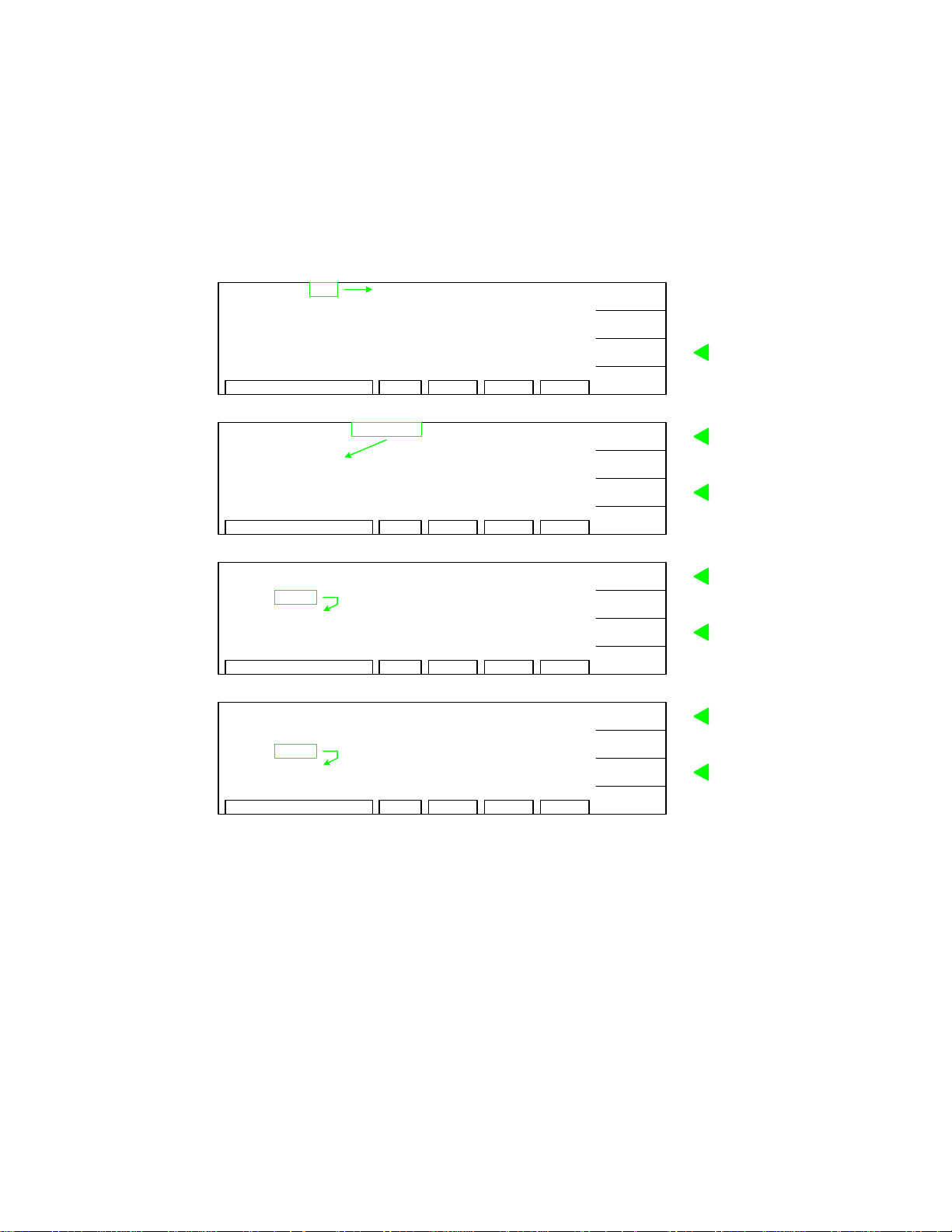
2.5 Programming an AC Hipot Test
This test is applicable to the Sentry 10, 20 and 30 Plus instruments. With the instrument in
‘stand-by’ status, press [F1] = PROGRAM. If continuing the 5-step example from ¶2.4, you are
already in program mode and on the AC test mode page. Follow the green arrows (!) on the
right side of this diagram to program the individual AC hipot test parameters.
[F1] = New
Program
Step 2 = AC
Select
AC
Test Mode
Set
Test Voltage
Set
High Current
Limit
VOLT
HIGH
TIME
VOLT
HIGH
TIME
VOLT
HIGH
TIME
VOLT
HIGH
TIME
0.000kV:
:
0.500mA
:
3.0s
:
0.000kV
:
0.500mA
:
3.0s
0.000kV:
: 0.500mA
:
3.0s
:
2.750kV
:
0.500mA
:
3.0s
LOWACSTEP 2/2
ARC
RAMP
FALL
RMT ERROFSTLOCKVoltage is 0
LOWACSTEP 2/2
ARC
RAMP
FALL
RMT ERROFSTLOCKSelect Mode
LOWACSTEP 2/2
ARC
RAMP
FALL
RMT ERROFSTLOCK0.05 - 5kV
LOWACSTEP 2/2
ARC
RAMP
FALL
RMT ERROFSTLOCK0.001 - 20mA
OFF
:
OFF
:
OFF
:
OFF
:
FIRST
MORE..
NEXT
EXIT
OFF
:
OFF
:
OFF
:
OFF
:
UP
DOWN
NEXT
EXIT
OFF
:
OFF
:
OFF
:
OFF
:
INC.
DEC.
NEXT
EXIT
OFF
:
OFF
:
OFF
:
OFF
:
INC.
DEC.
NEXT
EXIT
To change value in highlighted box.
F1
To delete or insert a test step.
F2
To move highlighted box around
F3
display to select parameter to change
To exit programming mode.
F4
Set MODE = AC
F1
F2
To move highlighted box to VOLT
F3
F4
To set test voltage:
F1
0.05 - 5kV in .001kV increments
F2
F3
To move highlighted box to HIGH.
F4
To set high current limit:
F1
0.001 - 20mA in .001mA increments
F2
To move highlighted box to TIME.
F3
F4
Set
Test Time
Test time = 0
then continuous
voltage until STOP
is pressed.
Set
Low Current
Limit
VOLT
HIGH
TIME
VOLT
HIGH
TIME
:
:
:
:
:
:
2.750kV
15.00mA
3.0s
2.750kV
15.00mA
10.0s
LOWACSTEP 2/2
ARC
RAMP
FALL
RMT ERROFSTLOCK0, 0.1 - 999s
LOWACSTEP 2/2
ARC
RAMP
FALL
RMT ERROFSTLOCK0 - 20mA 0 = OFF
OFF
:
OFF
:
OFF
:
OFF
:
INC.
DEC.
ENTER
EXIT
OFF
:
OFF
:
OFF
:
OFF
:
INC.
DEC.
NEXT
EXIT
To set test time:
F1
0, 0.1 - 999s in 0.1s increments
F2
F3
To move highlighted box to LOW.
F4
To set low current limit:
F1
0 - 20mA in 0.01mA increments
F2
F3
To move highlighted box to ARC.
F4
Continue on next page.
Operation Page 37 of 85
Page 38

Programming an AC Hipot Test (continued)
Set
Arc Limit
Set
Ramp Time
Set
Fall Time
Set
Next
Test Step
[F1]
: Program Step 3
or
[F4] : Exit Program Mode
VOLT
HIGH
TIME
VOLT
HIGH
TIME
VOLT
HIGH
TIME
VOLT
HIGH
TIME
:
2.750kV
:
15.00mA
:
10.0s
:
2.750kV
:
15.00mA
:
10.0s
:
2.750kV
15.00mA
::10.0s
2.750kV
:
:
15.00mA
:
10.0s
2/2
LOWACSTEP 2/2
ARC
RAMP
FALL
RMT ERROFSTLOCK1 - 20mA 0 = OFF
LOWACSTEP 2/2
ARC
RAMP
FALL
RMT ERROFSTLOCK0 - 999s 0 = OFF
LOWACSTEP 2/2
ARC
RAMP
FALL
RMT ERROFSTLOCK0 - 999s 0 = OFF
LOWACSTEP
ARC
RAMP
FALL
RMT ERROFSTLOCK1 - 10
:
:
:
:
:
:
:
:
:
:
:
:
:
:
:
:
3.00mA
OFF
OFF
OFF
3.00mA
OFF
OFF
OFF
3.00mA
OFF
3.0s
OFF
3.00mA
OFF
3.0s
3.0s
INC.
DEC.
NEXT
EXIT
INC.
DEC.
NEXT
EXIT
INC.
DEC.
NEXT
EXIT
NEW
MORE..
NEXT
EXIT
Set arc current limit:
F1
1-20mA in 0.1mA increments
F2
To move highlighted box to RAMP.
F3
F4
To set Ramp Time:
F1
0 - 999s in 0.1s increments
F2
F3
To move highlighted box to FALL.
F4
To set Fall Time:
F1
0 - 999s in 0.1s increments
F2
F3
To move highlighted box to STEP.
F4
F1
To set next test step = 3
F2
F3
To
exit
F4
programming mode and return
to STAND BY status.
END AC Hipot Test Programming. After selecting the FALL Time, one can either press [F1]
= NEW to change the step number in the highlighted box (1-10) and start programming STEP 310, OR
one can press [F4] = EXIT to exit programming function and return to STAND BY
status.
For this example, press [F1] = NEW and proceed to program step 3 as a DC Hipot Test (¶ 2.6).
Page 38 of 85 Operation
Page 39

2.6 Programming a DC Hipot Test
This test is applicable to the Sentry 20 and 30 Plus instruments. With the instrument in ‘standby’ status, press [F1] = PROGRAM. If continuing the 5-step example from ¶2.5, you are already
in program mode and on the AC test mode page. The example illustrated herein shows a GC test
as Step 1, an AC test as Step 2 and how to program a DC test in Step 3. Follow the green arrows
(!) on the right side of this diagram to program the individual DC hipot test parameters.
[F1] = New
Program
Step 3 = DC
VOLT
HIGH
TIME
:
:
0.000kV:
0.500mA
3.0s
LOWACSTEP 3/3
ARC
RAMP
FALL
RMT ERROFSTLOCKVoltage is 0
OFF
:
OFF
:
OFF
:
OFF
:
FIRST
MORE..
NEXT
EXIT
To change value in highlighted box.
F1
To delete or insert a test step.
F2
To move highlighted box around
F3
display to select parameter to change
To exit programming mode.
F4
Select
DC
Test Mode
Set
Test Voltage
Set
High Current
Limit
Set
Test Time
VOLT
HIGH
TIME
VOLT
HIGH
TIME
VOLT
HIGH
TIME
VOLT
HIGH
TIME
:
0.000kV
:
0.500mA
:
3.0s
0.000kV:
: 0.500mA
:
3.0s
:
2.500kV
:
0.500mA
:
3.0s
:
2.500kV
:
2.999mA
:
3.0s
LOWACSTEP 3/3
ARC
RAMP
FALL
RMT ERROFSTLOCKSelect Mode
LOWDCSTEP 3/3
ARC
RAMP
FALL
RMT ERROFSTLOCK0.05 - 6kV
LOWDCSTEP 3/3
ARC
RAMP
DWELL :
FALL
I-RUS
RMT ERROFSTLOCK0.0001 - 5mA
LOWDCSTEP 3/3
ARC
RAMP
FALL
I-RUS
RMT ERROFSTLOCK0, 0.1 - 999s
OFF
:
OFF
:
OFF
:
OFF
:
UP
DOWN
NEXT
EXIT
OFF
:
OFF
:
OFF
:
: OFFDWELL
OFF
:
OFF:I-RUS
INC.
DEC.
NEXT
EXIT
OFF
:
OFF
:
OFF
:
OFF
:
OFF
:
OFF
INC.
DEC.
NEXT
EXIT
OFF
:
OFF
:
OFF
:
OFFDWELL
:
OFF
OFF
:
INC.
DEC.
ENTER
EXIT
Set MODE = DC
F1
F2
To move highlighted box to VOLT
F3
F4
To set test voltage:
F1
0.05 - 6kV in .001kV increments
F2
F3
To move highlighted box to HIGH.
F4
To set high current limit:
F1
0.0001 - 5mA in .001mA increments
F2
To move highlighted box to TIME.
F3
F4
To set test time:
F1
0, 0.1 - 999s in 0.1s increments
F2
F3
To move highlighted box to LOW.
F4
Set
Low Current
Limit
VOLT
HIGH
TEST
:
:
:
2.500kV
2.999mA
5.0s
LOWDCSTEP 3/3
ARC
RAMP
DWELL :
FALL
I-RUS :
RMT ERROFSTLOCK0 - 5mA 0 = OFF
OFF
:
OFF
:
OFF
:
OFF
:
OFF
OFF
INC.
DEC.
NEXT
EXIT
To set low current limit:
F1
0 - 5mA in 0.001mA increments
F2
F3
To move highlighted box to ARC.
F4
Continue on next page.
Operation Page 39 of 85
Page 40

Programming an DC Hipot Test (Continued)
LOWDCSTEP 3/3
ARC
Set
Arc Limit
VOLT
HIGH
TIME
:
:
2.500kV
2.999mA
5.0s
RMT ERROFSTLOCK1 - 5mA 0 = OFF
RAMP
DWELL ::OFF
FALL
0.015mA
:
OFF
:
OFF:
:
OFF
:
:I-RUS OFF
INC.
DEC.
NEXT
EXIT
Set arc current limit:
F1
1-5mA in 0.1mA increments
F2
F3
To move highlighted box to RAMP.
F4
Set
Ramp Time
Set
Dwell Time
Set
Fall Time
Set
I-Rus Limit
VOLT
HIGH
TIME
VOLT
HIGH
TIME
VOLT
HIGH
TIME
VOLT
HIGH
TIME
:
2.500kV
:
2.999mA
:
5.0s
:
2.500kV
:
2.999mA
:
5.0s
:
2.500kV
2.999mA
::5.0s
2.500kV
:
2.999mA
:
5.0s
LOWDCSTEP 3/3
ARC
RAMP
DWELL
FALL
RMT ERROFSTLOCK0 - 999s 0 = OFF
LOWDCSTEP 3/3
ARC
RAMP
DWELL
FALL
RMT ERROFSTLOCK0 - 999s 0 = OFF
LOWDCSTEP 3/3
ARC
RAMP
DWELL 3.0s
FALL
RMT ERROFSTLOCK0 - 999s 0 = OFF
LOWDCSTEP 3/3
ARC
RAMP
DWELL 3.0s
FALL
I-RUS
RMT ERROFSTLOCK0, 0.5uA-5mA 0 = OFF
0.015mA
:
OFF
:
OFF
:
:
OFF
OFF
:
OFFI-RUS
:
0.015mA
:
OFF
:
:
3.0s
OFF
:
OFF
OFFI-RUS :
0.015mA
:
OFF
:
3.0s
:
:
:
OFF
:I-RUS OFF
0.015mA
:
OFF
:
3.0s:
:
:
3.0s
:
:
OFF
INC.
DEC.
NEXT
EXIT
INC.
DEC.
NEXT
EXIT
INC.
DEC.
NEXT
EXIT
INC.
DEC.
NEXT
EXIT
To set Ramp Time:
F1
0 - 999s in 0.1s increments
F2
F3
To move highlighted box to DWELL.
F4
To set Dwell Time:
F1
0 - 999s in 0.1s increments
F2
F3
To move highlighted box to FALL.
F4
To set Fall Time:
F1
0 - 999s in 0.1s increments
F2
F3
To move highlighted box to I-RUS.
F4
Set in-rush current limit:
0, 0.5uA -5mA
F1
in 0.001mA increments
F2
To move highlighted box to STEP.
F3
F4
Set
Next
Test Step
[F1]
: Program Step 4
[F4] : Exit Program Mode
or
VOLT
HIGH
TIME
:
:
:
3/3
2.500kV
2.999mA
5.0s
LOWDCSTEP
ARC
RAMP
FALL
I-RUS : OFF
RMT ERROFSTLOCK1 - 10
0.015mA
:
:
:
:
:
OFF
3.0s
3.0sDWELL
3.0s
NEW
MORE..
NEXT
EXIT
F1
To set next test step = 4
F2
F3
To
F4
to STAND BY status.
exit
programming mode and return
END DC Hipot Test Programming. After selecting the I-RUSH limit, press [F1] = NEW to change the step
number in the highlighted box (1-10) and start programming STEP 4-10, OR
press [F4] = EXIT to exit
programming function and return to STAND BY status.
For this example, press [F1] = NEW and proceed to program step 4 as an IR Test (¶ 2.7).
NOTE: The In-Rush current range is dependent on the programmed High Limit. Refer to Safety Features in the
Specifications section, page 8.
Page 40 of 85 Operation
Page 41
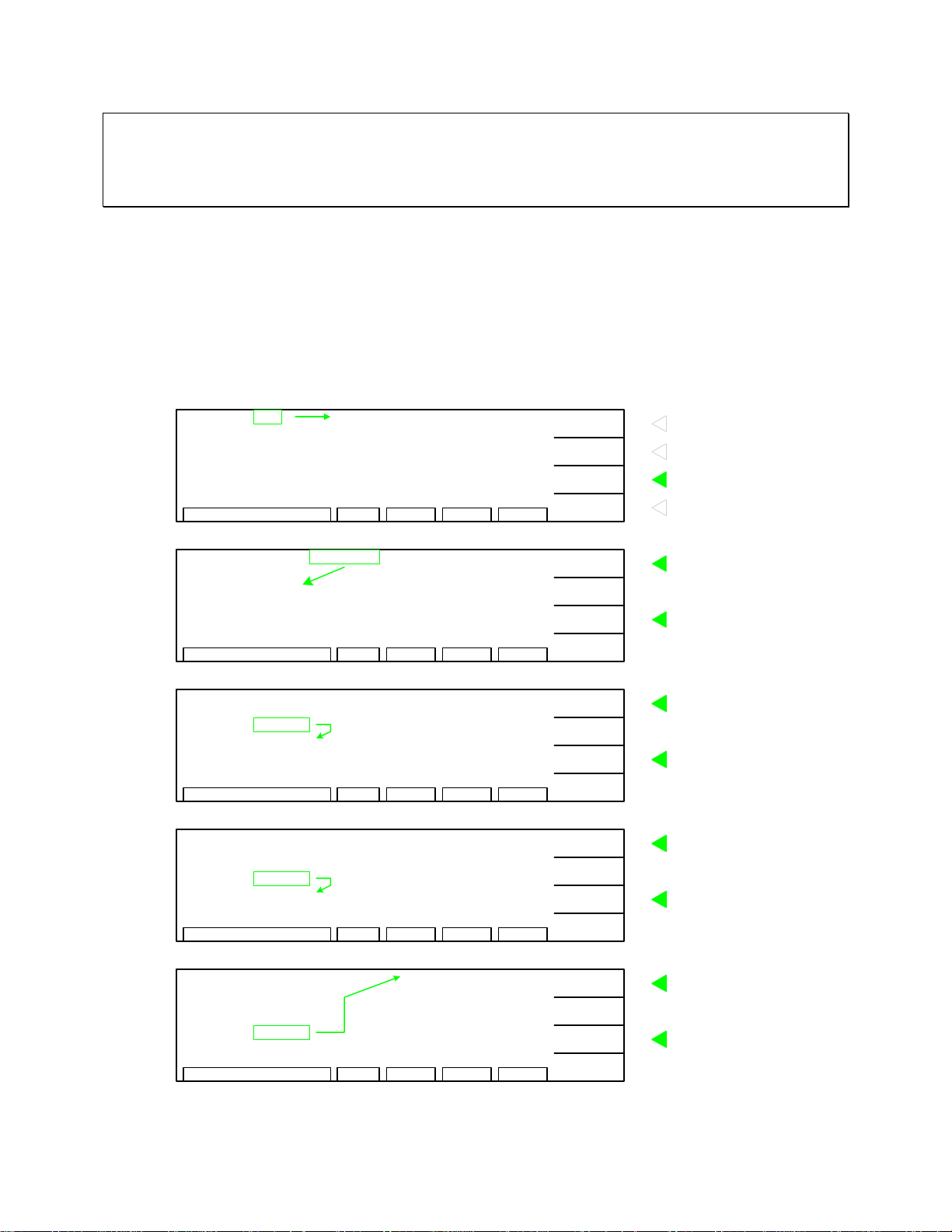
NOTE: In-Rush Current
The In-Rush current limit fo r the DC hipot test is a low limit which is monitored during init ial charging of the device
under test. When activated (other than Off), current below the programmed value is considered to be a Fail
condition. This current monitoring is generally used to check that the charging current to the device exceeds a
specified value (> programmed limit), thus ensuring that the device is properly connected to the tester.
2.7 Programming an IR (Insulation Resistance) Test
This test is applicable to the Sentry 30 Plus instrument. With the instrument in ‘stand-by’ status,
press [F1] = PROGRAM. If continuing the 5-step example from ¶2.6, you are already in
program mode and on the AC test mode page. This example shows a GC test as Step1, an AC
test as Step 2, a DC test as Step 3 and how to program an IR test in Step 4. Follow the green
arrows (!) on the right side of this diagram to program the individual IR test parameters.
[F1] = NEW
Program
Step 4 = IR
Select
IR
Test Mode
Set
Test Voltage
Set
Low
Resistance
Limit
VOLT
HIGH
TIME
VOLT
HIGH
TIME
VOLT
LOW
TIME
VOLT
LOW
TIME
4/4
0.000kV:
:
0.500mA
:
3.0s
:
0.000kV
:
0.500mA
:
3.0s
: 0.000kV
:
1.0M
Ω
:
3.0s
: 0.750kV
:
1.0M
Ω
:
3.0s
Ω
LOWACSTEP
ARC
RAMP
FALL OFF:
RMT ERROFSTLOCKVoltage is 0
LOWACSTEP 4/4
ARC
RAMP
FALL OFF:
RMT ERROFSTLOCKSelect Mode
HIGHIRSTEP 4/4
RAMP
DWELL OFF
FALL OFF
RMT ERROFSTLOCK0.05 - 1kV
HIGHIRSTEP 4/4
RAMP
DWELL :
FALL :
RMT ERROFSTLOCK0.1MΩ - 50G
OFF
:
OFF
:
OFF
:
FIRST
MORE..
NEXT
EXIT
:
OFF
:
OFF
:
OFF
UP
DOWN
NEXT
EXIT
OFF
:
OFF
:
:
:
INC.
DEC.
NEXT
EXIT
:
OFF
:
OFF
OFF
OFF
INC.
DEC.
NEXT
EXIT
F1
To change value of highlighted box.
F2
To delete or insert a test step.
F3
To move highlighted box to MODE.
F4
To exit programming mode.
F1
Set MODE = IR
F2
To move highlighted box to VOLT
F3
F4
To set test voltage:
F1
0.05 - 1kV in 0.001kV increments
F2
To move highlighted box to LOW.
F3
F4
To set low resistance limit:
0.1M - 50G
F1
F2
F3
F4
Ω
in 0.1MΩ increments
To move highlighted box to TIME.
Set
Test Time
VOLT
LOW
TIME
:
:
:
0.750kV
1.5M
Ω
3.0s
HIGHIRSTEP 4/4
RAMP
RMT ERROFSTLOCK0, 0.1 - 999s
:
OFF
:
OFF
:
OFFDWELL
OFFFALL
:
INC.
DEC.
NEXT
EXIT
To set dwell time:
F1
0, 0.1 -999s in 0.1s increments
F2
F3
To move highlighted box to HIGH.
F4
Continue on next page.
Operation Page 41 of 85
Page 42

Programming an IR (Insulation Resistance) Test (Continued)
Set
High
Resistance
Limit
Select
Ramp Time
Select
Dwell Time
Set
Fall Time
VOLT
LOW
TIME
VOLT
LOW
TIME
VOLT
LOW
TIME
VOLT
LOW
TIME
0.750kV
:
1.5M
:
Ω
:
5.0s
:
0.750kV
:
1.5M
Ω
:
5.0s
:
:
1.5M
Ω
:
5.0s
: 0.750kV
:
1.5M
Ω
:
5.0s
HIGHIRSTEP 4/4
RAMP
DWELL
FALL OFF
OFF
:
OFF
:
OFF
:
:
INC.
DEC.
NEXT
RMT ERROFSTLOCK0 - 50GΩ 0 = OFF
HIGHIRSTEP 4/4
RAMP
DWELL :
FALL
:
:
:
1.250G
OFF
OFF
OFF
Ω
EXIT
UP
DOWN
NEXT
RMT ERROFSTLOCK0 - 999s 0 = OFF
HIGHIRSTEP 4/4
RAMP
DWELL
FALL
:
:
:0.750kV
:
1.250G
3.0s
OFF
OFF
Ω
EXIT
UP
DOWN
NEXT
RMT ERROFSTLOCK0 - 999s 0 = OFF
HIGHIRSTEP 4/4
RAMP
1.250G
:
3.0s
:
3.0s:DWELL
:FALL OFF
Ω
EXIT
INC.
DEC.
NEXT
To set high resistance limit:
F1
0 - 50GΩ in 0.1MΩ increments
(from programmed low limit to 50GΩ)
F2
F3
To move highlighted box to RAMP.
F4
To set ramp time:
F1
0 - 999s in 0.1s increments
F2
To move highlighted box to DWELL.
F3
F4
To set ramp time:
F1
0 - 999s in 0.1s increments
F2
To move highlighted box to FALL.
F3
F4
To set fall time:
F1
0 - 999s in 0.1s increments
F2
F3
To move highlighted box to STEP.
F4
To set next test step = 5
F1
F2
To
F3
to STAND BY status.
F4
exit
programming mode and return
Set
Next
Test Step
[F1]
: Program Step 5
[F4] : Exit Program Mode
or
VOLT
LOW
TIME
4/4
: 0.750kV
:
1.5M
Ω
:
5.0s
RMT ERROFSTLOCK0 - 999s 0 = OFF
HIGHIRSTEP
RAMP
DWELL : 3.0s
:
:
1.250G
3.0s
3.0sFALL :
Ω
EXIT
NEW
MORE ..
NEXT
RMT ERROFSTLOCK1 - 10
EXIT
END IR Test Programming. After selecti ng th e F A LL Time, one can ei th er press [ F1] = N EW
to change the step number in the highlighted box (1-10) and start programming STEP 5-10, OR
one can press [F4] = EXIT to exit programming function and return to STAND BY status.
For this example, press [F1] = NEW and proceed to program step 5 as a PAUSE (¶ 2.8).
Page 42 of 85 Operation
Page 43
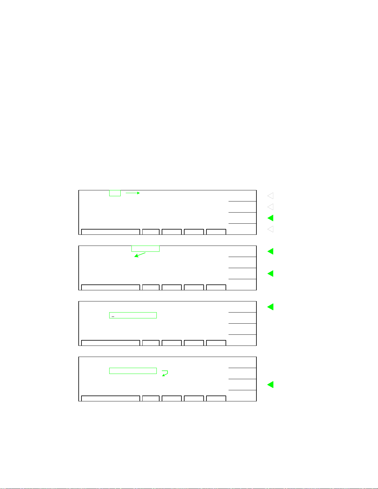
2.8 Programming a Pause in Test Sequence
“PAUSE” is a mode selection that allows a test sequence to be stopped while test leads are
changed or other operations performed. A 15-character user programmable message will be
displayed on the screen when in PAUSE mode and the test will continue when the [START]
button is pressed or when START is initiated via remote I/O. The Under Test relay on the
remote I/O can also be cycled during PAUSE if required. During the test sequence when
PAUSE is encountered the tester stops, displays PAUSE and 15-character message until START
button is pressed again (or START is initiated via remote I/O).
This mode is applicable to the Sentry 10, 20 and 30 Plus instruments. With the instrument in
‘stand-by’ status, press [F1] = PROGRAM. If continuing the 5-step example from ¶2.7, you are
already in program mode and on the AC test mode page. This example shows a GC test as
Step1, an AC test as Step 2, a DC test as Step 3, an IR test as Step 4 and finall y how to program
a Pause as Step5. Follow the green a rrows (!) on the right side of this diagram to program the
individual Pause mode parameters. Enter a message (length 1-15 characters) for the operator.
5/5
[F1] = NEW
Program
Step 5 = PA
Select
PA
Test Mode
Enter
Pause
VOLT
HIGH
TIME
VOLT
HIGH
PAUSE
UNDER TEST SIGNAL
0.000kV:
:
0.500mA
:
3.0s
:
0.000kV
:
0.500mA
:TIME 3.0s
:
PAUSE MODE
Message
Enter
Pause
PAUSE
UNDER TEST SIGNAL
CHANGE-DUT
:
Message
Continued on Next Page.
LOWACSTEP
ARC
RAMP
FALL OFF:
RMT ERROFSTLOCKVoltage is 0
LOWACSTEP 5/5
ARC
RAMP
FALL OFF:
RMT ERROFSTLOCKSelect Mode
PASTEP 5/5
:
OFF
RMT ERROFSTLOCK1 - 15 CHAR.
PASTEP 5/5
OFF
:
RMT ERROFSTLOCK1 - 15 CHAR.
OFF
:
OFF
:
OFF
:
FIRST
MORE..
NEXT
EXIT
OFF
:
OFF
:
OFF
:
UP
DOWN
NEXT
EXIT
UP
DOWN
NEXT C.
CANCEL
UP
DOWN
NEXT
CANCEL
To change value of highlighted box.
F1
To delete or insert a test step.
F2
To move highlighted box to MODE.
F3
To exit programming mode.
F4
F1
Set MODE = PA
F2
To move highlighted box to
F3
PAUSE
F4
To enter message:
1 - 15 characters: * + , - . /
F1
0 -9 and A - Z
F2
F3
To move cusor to next character.
F4
To erase message.
F1
F2
F3
To move highlighted box to UNDER.
F4
Operation Page 43 of 85
Page 44

Programming a PAUSE in test sequence (continued):
PASTEP 5/5
PAUSE
: CHANGE-DUT
Set
Test Signal
UNDER TEST SIGNAL
:
OFF
RMT ERROFSTLOCKOFF / ON
INC.
DEC.
NEXT
EXIT
To set test signal:
F1
OFF or ON
F2
F3
To move highlighted box to STEP.
F4
Exit
Program
Mode
5/5
PAUSE
UNDER TEST SIGNAL
CHANGE-DUT
::OFF
PASTEP
INC.
DEC.
NEXT
RMT ERROFSTLOCK1 - 10
EXIT
F1
F2
F3
F4
To set next test step
To
exit
programming mode and return
to STAND BY status.
END PA Mode Programming. For the sake of this 5-step example, after selecting the UNDER
TEST SIGNAL ON or OFF, press [F4] = EXIT to exit programming function and return to
STAND BY status.
Page 44 of 85 Operation
Page 45

2.9 Storing a Test Setup
NOTE:
Instrument PRESET values can be programmed and stored for your specific test setup. Therefo re
before storing your tests, program the preset values. Refer to p 2.11 for PRESET programming
information.
To store the previous example of the p rogrammed 5-step test, with the instrument in ‘STAND
BY’ status, press [F3] = MENU to access the memory function.
In MENU with the highlighted box around MEMORY, press [F3] = SELECT to enter the
memory function.
STAND BY
Display
MENU
0.1A
Ω
1.2
0.5s
1
MEMORY
2
SYSTEM
3
OPTION
4
CALIBRATION
5
KEY LOCK
LOWGCSTEP 1/5 0.3Ω:
RMT ERROFSTLOCKSTAND BY
RMT ERROFSTLOCKSELECT FUNC.
PROGRAM
PRESET
MENU
MORE..
LAST
DOWN
SELECT
EXIT
To enter programming mode.
F1
To view/change preset (initial) test
F2
parameters.
To view/change system parameters:
F3
memory, system, option, calibration, key
lock, password, error, & about.
To view the programmed test setups and
F4
access offset function.
F1
To toggle through MENU functions.
F2
To toggle through MENU functions.
F3
To enter MEMORY function.
F4
Return to STAND BY display.
To store a test setup in memory
F1
location 1-60
F2
Recall test in highlighted location.
F3
Delete test in highlighted location.
F4
Return to MENU display.
MEMORY
1
(0 STEPS)
2
(0 STEPS)
3
(0 STEPS)
4
(0 STEPS)
5
(0 STEPS)
STORE
RECALL
DELETE
RMT ERROFSTLOCKSELECT FUNC.
RETURN
Press [F1] = STORE to access the store function. Press [F2] = DOWN to move highlighted box
to the memory location (1-60) in which you wish to store this test setup. Press [F3] = SELECT
to accept location number.
To move highlighted box to
F1
memory location 60
To toggle through memory
F2
locations 1-60
To select highlighted memory
location and store previously
F3
programmed test setup
F4
Select
LOCATION
1
(0 STEPS)
2
(0 STEPS)
3
(0 STEPS)
4
(0 STEPS)
5
(0 STEPS)
LAST
DOWN
SELECT
RMT ERROFSTLOCKSEL. MEMORY
RETURN
Operation Page 45 of 85
Page 46

To label the selected location, press [F1] = UP (and/or [F2] = DOWN) to enter a combination
alpha-numeric name for this test setup. P ress [F3] = NEXT C. after each di git to accept that digit
and move on to the next. The name can be up to 10 characters long. When finished ent ering the
name, press [F3] = ENTER two times.
F1
To enter an alpha-numeric character
F2
To enter an alpha-numeric character
Accept entered character and move
F3
on to next character
F4
LABEL
Test Setup
1
(0 STEPS) _
(0 STEPS)
2
(0 STEPS)
3
(0 STEPS)
4
(0 STEPS)
5
UP
DOWN
NEXT C.
RMT ERROFSTLOCKSELECT FUNC.
CANCEL
F1
F2
Press 2 Times to exit LABEL
F3
function
F4
Exit
Label
Function
1
(0 STEPS)
2
(0 STEPS)
3
(0 STEPS)
4
(0 STEPS)
5
(0 STEPS)
123
UP
DOWN
NEXT C.
RMT ERROFSTLOCKSEL. MEMORY
CANCEL
The display will prompt: STORE TO #? Press [F1] = YES to accept storage to that memory
location # or [F2] = NO to reject storage. Press [ F4] = RETURN once to return to “MENU”
display. Press [F4] a second time to return to “STAND BY” display.
F1
Store test setup to location #1
F2
F3
F4
F1
F2
F3
Return to MENU display.
F4
Confirm
STORE
MEMORY
1
(0 STEPS) 123
2
(0 STEPS)
3
(0 STEPS)
STORE TO 1?
4
(0 STEPS)
5
(0 STEPS)
1
(5 STEPS) 123
2
(0 STEPS)
3
(0 STEPS)
4
(0 STEPS)
5
(0 STEPS)
RMT ERROFSTLOCK
RMT ERROFSTLOCKSELECT FUNC.
YES
NO
STORE
RECALL
DELETE
RETURN
LOWGC
PROGRAM
PRESET
MENU
MORE..
F1
F2
F3
F4
STAND BY
Display with
Memory ID
0.1A
Ω
1.2
0.5s
1/5M01 0.3Ω:
RMT ERROFSTLOCKSTAND BY
The MEMORY RECALL and DELETE functions work the same way as STORE. When the
instrument returns to STAND BY status there will be a tag “Mxx” in the upper left hand corn er
of the display to indicate which memory location is in use (displayed).
Page 46 of 85 Operation
Page 47

2.10 Programming a Multi-Step Test
Paragraphs 2.4, 2.5, 2.6, 2.7 and 2.8 illustrate the programming of a 5-step test (GC, AC, DC, IR
& PA). To program a multiple step test, power-up the Sentry Plus Series instrument so the
‘Stand By’ display is shown (Figure 2-2). Press [F1] = PROGRAM and enter the test
parameters for the first test (GC). After specif ying LOW resistance limi t, press [ F3] = NEXT and
[F1] = NEW to enter test parameters for the second test (AC). At this time, do NOT press [F4] =
EXIT because this will exit you from programming mode. After specifying FALL time for the
second test press [F3] = NEXT to continue entering test parameters for the third test (DC).
Continue this process for up to 10 steps. When finished entering desired number of test steps,
press [F4] = EXIT to exit programming mode and return to Stand By status.
In Stand By status, to view the test steps just programmed press [F4] = MORE. Figure 2-4
illustrates the Stand By display and resultant test steps display if the programming example in
paragraphs 2.4-2.8 was followed.
STAND BY
with
Memory ID
0.1A
1.2
Ω
0.5s
LOWGC1/5M01 0.3Ω:
RMT ERROFSTLOCKSTAND BY
PROGRAM
PRESET
MENU
MORE..
F1
F2
F3
F4
Continuing with the 5-step example, press [F4] = MORE to view
the 5 test steps (GC, AC, DC, IR & PA) stored to location 1.
Test
Steps
M01
1
2
3
4
5
OUTPUT
0.1A
GC
2.750kV
AC
2.500kV
DC
IRPA0.750kV
OFF
MEASURE RESULT
Ω
1.2
15.00mA
2.999mA
1.5M
Ω
RMT ERROFSTLOCKSTAND BY
------------
------------
------------
------------
------------
OFFSET
EXIT
F1
F2
F3
F4
Figure 2-4: View Programmed Test Setups
Operation Page 47 of 85
Page 48

2.11 PRESET Test Parameters
A number of initial parameters or default conditions may be programmed and stored as the
‘power-up’ conditions. On the Sentry Plus Series instruments, this function is labeled PRESET
and is accessible on the STAND BY display.
The PRESET values are stored with each programmed test. Therefore each memory location
may have different PRESET values. It is important to set the PRESET values prior to storing a
test program.
Table 2-3 lists the Sentry Plus Series PRESET test parameters including parameter range and
initial (default) value.
Table 2-3: PRESET Test Parameters
Parameter Range Initial
(Default)
Value
AC-V FREQ. 50 or 60Hz 60Hz Set frequency for AC Hipot test
SOFT. AGC ON or OFF ON Set software automatic gain control function
WV AUTO RANGE ON or OFF OFF Set hipot auto range function ON or OFF
IR AUTO RANGE ON or OFF ON Set resistance auto range function ON or OFF
GFI ON or OFF ON Set ground fa ult interrupt to trip at 0.5mA
FAIL RESTART ON or OFF OFF Fail continue steps
Description
ON or OFF
2.11.1 AC-V FREQ.
The AC-V Frequency setting allows the user to select the line frequency for the AC hipot test.
The range of AC-V Freq. is 50 or 60Hz and the instrument default setting is 60Hz.
2.11.2 SOFTWARE AGC
The Software Automatic Gain Control (SOFT AGC) setting allows the option of correcting the
output voltage when ON. This is satisfactory when measuring resistors but under special
circumstances when measuring large capacitive devices it is best to select Software AGC OFF.
The default value is ON.
2.11.3 WV AUTO RANGE
The WV Auto Range setting allows the option of using the full scale current range (ON) or using
the user programmed maximum current limit (OFF) during a withstand voltage (hipot) test. The
low current range (3mA full scale) results in increased measurement resolution. The default
value of WV Auto Range is OFF.
Page 48 of 85 Operation
Page 49

2.11.4 IR AUTO RANGE
The IR Auto Range setting allows the option of using the full scale current range (ON) or using
the user programmed maximum current lim it (OFF). To increase measurement resolution in IR
mode, select IR Auto Range ON. To increase measurement speed in IR mode, select IR Auto
Range OFF. The instrument default value for IR Auto Range is ON.
2.11.5 GFI
The Ground Fault Interrupt (GFI) function can be programmed ON or OFF and the instrument
default setting is ON. When GFI is activated, the ground fault interrupt circuit detects leakage
current to ground. If the leakage is >0.5mA, the high voltage will be shut down in less than
0.5ms.
NOTE:
When using the Sentry Plus instrument with the Sentry 50 Ground Bond Tester,
GFI must be turned OFF.
2.11.6 FAIL RESTART
The FAIL RESTART function can be programmed ON or OFF and the instrument default setting
is OFF. When the Fail Restart function is turned ON, the Sentry Plus instrument does not
require the STOP button to be pressed to restart the test. This mode is typically used in
conjunction with the remote I/O connections to automatically restart the test when a failure
occurs. This can be done by connecting one Fail contact (pin 8) to the Start contact (pin 5) and
the other Fail contact (pin 9) to the COM contact (pin 3).
Operation Page 49 of 85
Page 50

2.12 Instrument Offset
The Sentry Plus Series instrument provides automatic offset for lead and/or fixture effects.
During the offset process a correction is made (subtracted out) as the result of the measured
current with no DUT attached. For maxim um measurement ac curacy it is recom mended that the
OFFSET function be performed on the Sentry Plus Series instrument after power up, any time
the test parameters are changed and any time the test leads or fixture is changed. Return and HV
test leads should not be connected together (open circuit) fo r AC and DC hipot tests. Return an d
GC test leads should be connected (short circuit) for a GC test. There is no offset in an IR test.
Once the Offset function is turned ON for a spe cific program, it can be stored in memory with
that program. If the program parameters are changed the offset function will automatically turn
OFF and the offset function will be need to be performed again to get the new offset value. It
will then need to be restored in memory.
Prior to performing the OFFSET function:
•
•
•
Allow the instrument to warm up for 15 minutes.
Connect the Test cables (or fixture) to the OUTPUT and RTN/LOW connectors.
Program the test steps.
With the instrument in STAND BY status:
•
•
•
•
•
•
•
•
Press [F4] = MORE
Press [F3] = OFFSET
Follow instructions on display: i.e.: connect OPEN across OUTPUT terminal.
Press green [START] button.
Wait while instrument gets OFFSET value.
The OFST block at the bottom of the display is now highlighted (back lit).
Press [F4] = MORE to return to STAND BY status.
OR
To undo the OFFSET function:
•
•
•
•
Press [F3] = OFFSET
Follow prompt on display: “Turn off the offset function?”
Press [F3] = ENTER to turn off OFFSET function.
The OFST block at the bottom of the display is not highlighted now.
The following formulas apply to the offset function:
For Offset Current
Display Current
For Offset Current > 100mA:
Display Current Measured Total Current Offset Total Current-=
100mA:
Measured Total Current Offset Total Current
=-
22
Page 50 of 85 Operation
Page 51

OFFSET Function
There is no offset in the IR or PA modes. Using the pre-programmed example from paragraphs
2.4-2.8 of the GC, AC, DC, IR & PA 5-step test the resultant error and correction is illustrated
herein.
0.3
Ω
PROGRAM
PRESET
MENU
MORE..
F1
F2
F3
F4
To access OFFSET function.
"STAND BY"
Display
with
Memory ID
M01 :
LOWGCSTEP 1/5
0.1A
1.2
Ω
0.5s
RMT ERROFSTLOCKSTAND BY
[F4]
GET
OFFSET
OFFSET
VALUES
M01 MEASURE RESULT
1
2AC
3
4
5GCPA
OUTPUT
0.1A
2.750kV 15.00mA
DCIR2.500kV
0.750kV 1.5M
CHANGE-DUT
1.2
Ω
2.999mA
Ω
-------------
-------------
-------------
-------------
-------------
RMT ERROFSTLOCKSTAND BY
1.
PLEASE OPEN THE HV
OUTPUT TERMINAL.
2.
NO OFFSET IN IR MODE.
PRESS TEST KEY TO GET OFFSET..
RMT ERROFSTLOCK
M01 MEASURE RESULT
1
2AC
3
4
5GCPA
OUTPUT
0.1A
2.753kV 0.07mA
DCIR2.499kV
0.750kV 1.5M
CHANGE-DUT
0.1
Ω
0.002mA PASS
Ω
PASS
PASS
SKIPPED
RMT ERROFSTLOCKU.T.S = OFF
M01 5/5 PA
1.2.PAUSE: CHANGE-DUT
UNDER TEST SIGNAL: OFF
PRESS TEST KEY TO CONTINUE..
U.T.S = OFF
RMT ERROFSTLOCK
OFFSET
MORE..
CANCEL
MORE..
MORE..
F1
F2
To enter OFFSET function.
F3
To return to STAND BY status
F4
F1
F2
F3
F4
F1
F2
F3
F4
F1
F2
F3
F4
START
START
To GET OFFSET values
M01 5/5 PA
1.2.PAUSE: CHANGE-DUT
UNDER TEST SIGNAL: OFF
PASS
PASS
RMT ERR
LOCK
OFST
MORE..
F1
F2
F3
F4
After PASS Screen, press [STOP] and screen reverts to STAND BY display.
Continue on Next Page.
Operation Page 51 of 85
Page 52

Offset (continued)
To turn to Offset function OFF, and return to STAND BY status, follow the screens herein.
[F4]
M01 :
LOWGC1/5 0.3
0.1A
1.2
Ω
0.5s
RMT ERR
LOCKSTAND BY
OFST
Ω
PROGRAM
PRESET
MENU
MORE..
F1
F2
5-Steps Programmed
F3
F4
Offset ON
Ready to Test
M01 MEASURE RESULT
1
2AC
3
[F4]
[F3]
[F4]
DCIR2.500kV
4
5GCPA
M01 5/5 PA
PLEASE OPEN THE H.V.
1.
OUTPUT TERMINAL.
2.
NO OFFSET IN IR MODE.
M01 MEASURE RESULT
1
2AC
3
DCIR2.499kV
4
5GCPA
M01 :
0.1A
[F4]
1.2
0.5s
End Offset Function.
OUTPUT
0.1A
2.750kV 15.00mA
0.750kV 1.5M
CHANGE-DUT
OUTPUT
0.1A
2.753kV 0.07mA
0.750kV 1.5M
CHANGE-DUT
1.2
Ω
2.999mA --------
0.1
Ω
0.002mA -------
Ω
--------
--------
Ω
RMT ERR
RMT ERR
Ω
--------
--------
LOCKPASS
LOCK
-------
-------
-------
-------
OFST
OFST
RMT ERROFSTLOCKPASS
LOWGCSTEP 1/5 0.3
Ω
RMT ERROFSTLOCKSTAND BY
OFFSET
MORE..
OFF
CANCEL
OFFSET
MORE..
PROGRAM
PRESET
MENU
MORE..
F1
F2
Turn select
F3
Offset function
F4
F1
Turn Offset OFF
F2
F3
F4
Go to Results page
F1
F2
F3
F4
Go to STAND BY page
F1
F2
5-Steps Programmed
F3
F4
Offset OFF
Ready to Test
Page 52 of 85 Operation
Page 53

2.13 Connection to Device under Test
Figure 2-5 illustrates the connection of the Sentry Plus Series unit to a single DUT using the S02
1-meter HV cable set that comes standard with the instrument. The custom white banana
plug/red alligator clip is connected between the OUTPUT terminal on the Sentry Plus Series unit
and the high side of the device under test. The black banana plug/alligator clip is connected
between the RTN/LOW terminal on the Sentry Plus Series unit to the low side of the DUT.
STOP
START
Q
uadTech
M1
1.250kV
0.500mA
3.0s
STAND BY OFST
01
Sentry 30 Plus AC/DC/IR Hipot Tester
STEP 1/5
CAL UPDATE
AC
RMT LOCK ERR
LOW: OFF
ARC: OFF
RAMP: OFF
FALL: OFF
CAUTION
6kVDC
F1
F2
F3
F4
RTN/LOW
PROGRAM
PRESET
MENU
MORE..
DANGERPASS FAIL
!
Max 5kVAC
F1
F2
F3
F4
OUTPUT
S02
Cable
Set
+-
DUT
Figure 2-5: S02 Cable Connection
Refer to paragraphs 3.2 through 3.7 for the description and illustration of the connection of
several QuadTech accessories to the Sentry Plus Series instrument.
Operation Page 53 of 85
Page 54

2.14 Measurement Procedure
Before a measurement is made verify the following:
1. Sentry Plus Series instrument [POWER] ON.
2. 15-minute warm-up.
3. Test parameters programmed and shown on STAND BY display.
4. Test cables or fixture connected.
5. Offset Function initiated.
6. Device under test connected.
The operator has the option of performing a test at power-up conditions (test conditions at which
the instrument was last powered down) or recalling one of 60 stored test setups. Refer to
paragraphs 2.4 – 2.9 for test programming and storage/recall instructions.
To initiate a test:
•
•
•
•
•
•
Press [STOP] to make sure instrument is in STAND BY status.
Press [START]. DANGER led flashes. Status window shows UNDER TEST.
The test voltage is shut off when all test steps are completed,
OR when a test result is judged a FAIL per programmed test limits,
OR when the [STOP] button is pressed.
Press [STOP] at any time to terminate the output voltage and stop the test.
The Sentry Plus Series instrument judges the measurement value as GOOD or NO GOOD. A
GOOD judgment means the DUT passed all programmed steps. Upon com pletion of the test the
output voltage is terminated and the display shows PASS. The rear panel PASS signal is
functional and the buzzer sounds (if not turned OFF in SYSTEM parameters under MENU).
If a multiple step test is running and one step in the sequence fails, the Sentry Plus instrument
will not continue with the remaining steps
If the measurement value of the test (or any one step of the test) does not meet programmed
limits, the DUT is judged as NO GOOD, the display will show FAIL and the buzzer will sound
until the [STOP] button is pressed. The [STOP] button may be pressed at any time to terminate
the output voltage and stop the test.
Page 54 of 85 Operation
Page 55

Error Messages (FAIL result)
When the measurement value was judged NO GOOD and FA IL is shown on the di spla y, an error
message denoting the test result will be shown on the display also. Table 2-4 lists the possible
error messages for a NO GOOD/FAIL judgment.
Table 2-4: Error Messages
Error Message Description
HIGH FAIL Measured value (current or resistance) is over the programmed high limit.
LOW FAIL Measured value (current or resistance) is below the programmed low limit.
ARC FAIL Current arc is over the programmed high limit.
I/O FAIL Hardware Current Limit exceeded. Check DUT for short.
VOLTAGE OVER Voltage reading is greater than the hardware allo wable # of digits.
CURRENT OVER Current reading is greater than the hardware allowable # of digits.
GFI TRIPPED Ground Fault Interrupt is No Good.
NO OUTPUT Output is too Low. (Try increasing test time)
INRUSH FAIL Charging Current is over limit. (Check test fixture)
MEMORY FULL Greater than 60 tests/slot have been stored.
Operation Page 55 of 85
Page 56

2.15 MENU Parameters
With the Sentry Plus Series instrument in STAND BY status, press [F3] = MENU to access
programmable instrument parameters. The MENU display contains the Memory, System,
Option, Calibration, Key Lock, Change Password, Error Log and About functions. Table 2-5
lists these functions with description and default values.
Table 2-5: MENU Parameters
MENU # Parameter Function
1 MEMORY Store, Recall or Delete a test setup from
instrument memory
2 SYSTEM Change display contrast
Change beeper volume
Enable EN 50191 Current limit
Enable DC 50V AGC
3 OPTION Multi-Link function, currently unavailable
4 CALIBRATION Enter instrument calibration routine
Qualified service personnel only.
5 KEY LOCK Lock out front panel program access.
6 CHANGE PASSWORD Change key lock (user) password.
7 ERROR LOG View status of error queue.
8 ABOUT Instrument Information
Manufacturer, software version, etc
STAND BY
MENU
MENU
0.1A
1.2
Ω
0.5s
MEMORY
1
SYSTEM
2
OPTION
3
CALIBRATION
4
KEY LOCK
5
CHANGE PASSWORD
6
ERROR LOG
7
ABOUT
8
MEMORY
1
SYSTEM
2
LOWGCSTEP 1/5M01 OFF:
RMT ERROFSTLOCKSTAND BY
RMT ERROFSTLOCKSTAND BY
RMT ERROFSTLOCKSTAND BY
Figure 2-6: Menu Display
PROGRAM
PRESET
MENU
MORE..
LAST
DOWN
SELECT
EXIT
LAST
DOWN
SELECT
EXIT
F1
F2
Press F3 = "MENU"
F3
To set/change preset parameters
F4
F1
Press F2 = "DOWN" 5 times to
F2
view complete menu choices
F3
F4
F1
F2
F3
F4
Page 56 of 85 Operation
Page 57

2.15.1 MEMORY
Within the MEMORY function is the ability to STORE, RECALL or DELETE test setups, preset
parameters and offset values. There are 60 memory locati ons avail able and a single loc ation ma y
contain 1-10 steps. The total memory array is 60 and the instrument uses up to 10 locations to
run the test(s). If a 3-step test is programmed th en the instrument uses 3 additional steps to run
the test. Therefore five 10-step sequences, fift y-nine 1-step sequences or a combination therein
could be programmed. If more than 50 locations are stored, then the Sentry Plus will prompt
“memory full” when the store function is accessed again.
F1
To move to #8, About.
F2
To toggle through MENU functions.
F3
To enter MEMORY function.
F4
Return to STAND BY display.
To store a test setup in memory
F1
location 1-60
F2
Recall test in highlighted location.
F3
Delete test in highlighted location.
F4
Return to MENU display.
MENU
MEMORY
MEMORY
1
SYSTEM
2
OPTION
3
CALIBRATION
4
KEY LOCK
5
(0 STEPS)
1
(0 STEPS)
2
(0 STEPS)
3
(0 STEPS)
4
(0 STEPS)
5
LAST
DOWN
SELECT
RMT ERROFSTLOCKSELECT FUNC.
EXIT
STORE
RECALL
DELETE
RMT ERROFSTLOCKSELECT FUNC.
RETURN
Select
LOCATION
LABEL
Confirm
STORE
MEMORY
1
(0 STEPS)
2
(0 STEPS)
3
(0 STEPS)
4
(0 STEPS)
5
(0 STEPS)
(0 STEPS)
1
(0 STEPS)
2
(0 STEPS)
3
(0 STEPS)
4
(0 STEPS)
5
1
(0 STEPS)
2
(0 STEPS)
3
(0 STEPS)
STORE TO 1?
4
(0 STEPS)
5
(0 STEPS)
(5 STEPS) 123
1
(0 STEPS)
2
(0 STEPS)
3
(0 STEPS)
4
(0 STEPS)
5
123
LAST
DOWN
SELECT
RMT ERROFSTLOCKSEL. MEMORY
RETURN
UP
DOWN
NEXT C.
RMT ERROFSTLOCKSEL. MEMORY
CANCEL
YES
NO
RMT ERROFSTLOCK
STORE
RECALL
DELETE
RMT ERROFSTLOCKSELECT FUNC.
RETURN
Figure 2-7: Memory Function
To move highlighted box to
F1
memory location 60
To toggle through memory
F2
locations 1-60
To select highlighted memory
F3
location and store previously
programmed test setup
F4
F1
F2
Press 2 Times to exit LABEL
F3
function
F4
F1
Store test setup to location #1
F2
F3
F4
F1
F2
F3
F4
Return to MENU display.
Operation Page 57 of 85
Page 58

To Recall a Test Setup:
With the Sentry Plus instrument in Stand By status:
Press [F3] = MENU.
Press [F3] = SELECT to select MEMORY from the menu parameters list.
Press [F2] = RECALL to select the recall function.
Press [F1] = LAST or [F2] = DOWN to toggle through the test steps.
When the highlighted box is around the test step you want (3. 3 steps),
Press [F3] = SELECT.
The Sentry Plus instrument will prompt: “Recall From 3?”
Press [F1] = YES to recall the test setup or [F2] = NO to select another test setup.
Press [F4] = RETURN to go back to the MENU display.
Press [F4] = EXIT to return the instrument to STAND BY status.
When the Sentry Plus has Key Lock turned ON, the user has the option to lock out recall or
allow for programs to be recalled. If Recall is allowed when Key Lock is ON, then the Recall
function is accessible from the Stand By Menu. This lets the operator recall a memory location
without having to navigate through the menu system.
STAND BY
0.1A
1.2
Ω
0.5s
STAND BY
LOWGC1/5M01 0.3Ω:
RMT ERROFST
LOCK
KEY LOCK
RECALL
MENU
MORE..
F1
To change Key Lock Status to OFF
F2
To recall test setup from Memory
F3
F4
To Recall with Key Lock ON in STAND BY status:
Press [F2] = RECALL
Press [F1] = LAST or [F2] = DOWN to toggle through test setups.
When the desired test setup is highlighted (backlit):
Press [F3] = SELECT and you will automatically return to STAND BY status.
To DELETE a Test Setup:
With the Sentry Plus instrument in Stand By status:
Press [F3] = MENU.
Press [F3] = SELECT to select MEMORY from the menu parameters list.
Press [F3] = DELETE to select the delete function.
Press [F1] = LAST or [F2] = DOWN to toggle through the test steps.
When the highlighted box is around the test step you want (3. 3 steps),
Press [F3] = SELECT.
The Sentry Plus instrument will prompt: “Delete From 3?”
Press [F1] = YES to delete the test setup or [F2] = NO to select another test setup.
Press [F4] = RETURN to go back to the MENU display.
Press [F4] = EXIT to return the instrument to STAND BY status.
Page 58 of 85 Operation
Page 59
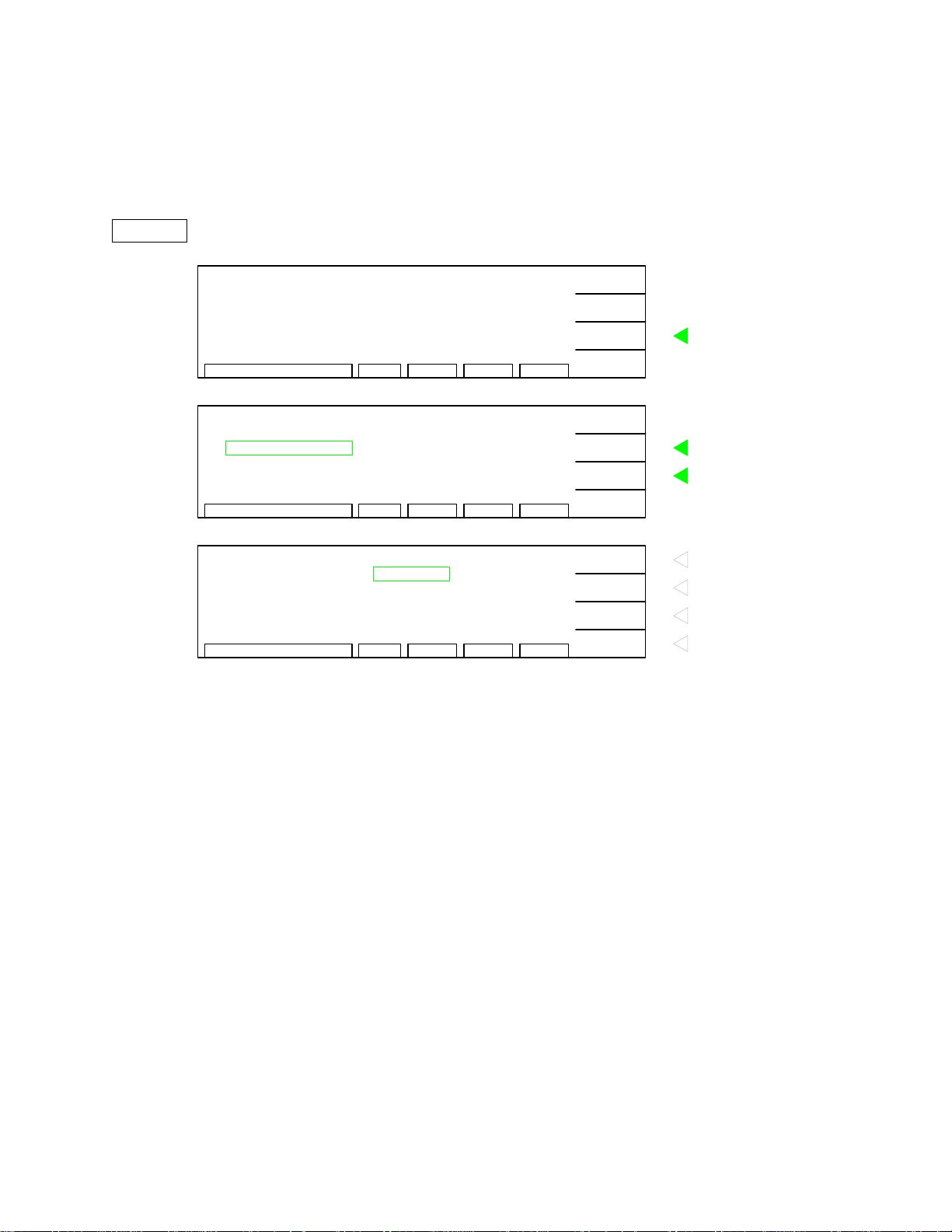
2.15.2 SYSTEM
Within the SYSTEM function are four programmable parameters: Contrast, Beeper Volume,
EN50191 and DC 50V AGC. With the instrument in Stand By status, access these system
parameters by pressing [F3] = MENU. Press [F2] = DOWN to move the highlighted box to
SYSTEM.
STAND BY
0.1A
1.2
0.5s
Ω
LOWGCSTEP 1/5M01 0.3Ω:
RMT ERROFSTLOCKSTAND BY
PROGRAM
PRESET
MENU
MORE..
F1
F2
Press F3 = "MENU"
F3
To change instrument parameters
F4
F1
Press F2 = "DOWN" to move
F2
highlighted box to SYSTEM
Press F3 = "SELECT" to enter
F3
SYSTEM parameters
F4
Press F1 = "INC." to increase
F1
brightness of display
Press F2 = "DEC." to decrease
F2
brightness of display
Press F3 = "NEXT" to move
F3
highlighted box to Buzzer Volume
Press F4 = "RETURN" to go back
F4
to MENU display
MENU
SYSTEM
MEMORY
1
SYSTEM
2
OPTION
3
CALIBRATION
4
KEY LOCK
5
1
CONTRAST
2
BUZZER VOLUME
3
EN 50191
4
DC 50V AGC
LAST
DOWN
SELECT
RMT ERROFSTLOCKSELECT FUNC.
:
15
:
OFF
:
OFF
:
ON
RMT ERROFSTLOCK1 - 15
EXIT
INC.
DEC.
NEXT
RETURN
2.15.2.1 CONTRAST
The CONTRAST parameter adjusts the brightness of the LCD display. The range is 1-15 with
15 being the brightest and 1 being the darkest. The initial default setting is 7.
2.15.2.2 BEEPER VOLUME
The BEEPER VOLUME can be adjusted from L (low) to M (medium) to H (high, loud) or it can
be turned OFF. The initial default setting is H (a loud pitch).
2.15.2.3 EN50191
The EN50191 function sets the maximum leakage current at 3mA AC or 5mA DC in accordance
with the European standard. When EN50191 is ON, the Sentry Plus Series instrument will
terminate the voltage at the output terminals when the leaka ge current ex ceeds 3mA AC or 5mA
DC. The EN 50191 function can be set ON or OFF and the initial setting is OFF.
Operation Page 59 of 85
Page 60

EN50191 (The Erection and Operation of Electrical Test Installations) specifies safet y guidelines
for both the test equipment and stations used in production lines, laboratories, test houses and
other test environments. The 3mA AC/5mA DC leaka ge curr ent li mi t is just one electrical sa fety
measure in attempting to specify ‘full protection from live parts’ for the operator and the DUT.
2.15.2.4 DC 50V AGC
The Automatic Gain Control (AGC) circuit is used to keep the output sign al of a circuit constant
as the amplitude of the input signal varies. So when the DC 50V AGC function is ON, the output
voltage is held constant at 50V for a DC hipot test. The DC 50V AGC function can be set ON or
OFF and the initial default setting is ON. This applies to a programmed voltage of 50V only.
NOTE:
Only in highly specialized applications should the DC 50V AGC function be set to OFF. The default value is ON
because in normal test modes, it is necessary to keep the output signal constant as the amplitude of the input signal
varies to obtain stable results.
2.15.3 OPTION
Within the OPTION function is the multi-link parameter. The multi-link function is not available
in the current software version. This option may be available in future software updates.
2.15.4 CALIBRATION
The CALIBRATION function requires a password to enter the instrument routine. Only
qualified service personnel with NIST traceable standards should perform instrument calibration.
Refer to paragraph 4.3 for the full Sentry Plus Series calibration procedure.
Page 60 of 85 Operation
Page 61

2.15.5 KEY LOCK
To lock out the PROGRAM, PRESET and MENU functions of the Sentry Plus Series instrument
use the KEY LOCK function in the MENU parameters. The initial instrument setting is OFF. To
activate the KEY LOCK function with the instrument in STAND BY status:
•
•
•
Press [F3] = MENU
Press [F2] = DOWN until KEY LOCK is backlit.
Press [F3] = SELECT
STAND BY
MENU
•
•
•
KEYLOCK
0.1A
1.2
0.5s
1
MEMORY
2
SYSTEM
3
OPTION
4
CALIBRATION
KEY LOCK
5
LOWGCSTEP 1/5M01 0.3
Ω
RMT ERROFSTLOCKSTAND BY
RMT ERROFSTLOCKSELECT FUNC.
Ω
:
PROGRAM
PRESET
MENU
MORE..
UP
DOWN
SELECT
EXIT
F1
F2
Press F3 = "MENU"
F3
To change instrument parameters
F4
F1
Press F2 = "DOWN" to move
F2
highlighted box to KEY LOCK
Press F3 = "SELECT" to enter
F3
KEY LOCK function
F4
Display prompts ‘USER PASSWORD’
Press [A] [A] [A] [A ] [E N T E R]
NOTE: AAAA is the default password. If password has been changed use the new
password.
Press F1 = "A" to input password
KEY LOCK
USER PASSWORD
RMT ERROFSTLOCK1 - 10 CHAR.
xxxx
A
B:
ENTER
RETURN
F1
character
Press F2 = "B" to input password
F2
character
Press F3 = "ENTER" to enter
F3
whole password
Press F4 = "RETURN" to go back
F4
to MENU display
Operation Page 61 of 85
Page 62
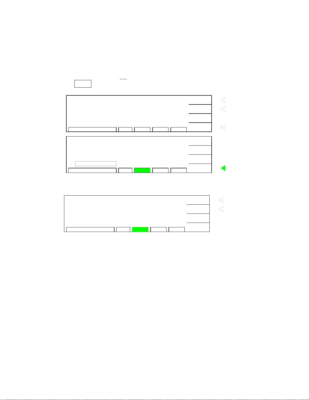
KEY LOCK (continued)
•
•
•
•
•
Display prompts ‘RECALL LOCK?’
NOTE: This means: “Do you want to lock out the ability to recall memory locations?”
Press [F1] = YES to select KEY LOCK ON.
NOTE: Selecting YES disallows the recalling of programmed tests from memory.
The LOCK block at bottom of display is backlit.
KEY LOCK ON!
KEYLOCK
RECALL LOCK?
Press F1 = "YES" to turn ON key
YES
NO
RMT ERROFSTLOCKYES / NO
CANCEL
F1
lock function
Press F2 = "NO" to turn OFF key
F2
lock function
F3
Press F4 = "CANCEL" to go back
F4
to MENU display
F1
F2
F3
Press F4 = "EXIT" to go back to
F4
STAND BY display
MENU
1
MEMORY
2
SYSTEM
3
OPTION
4
CALIBRATION
KEYLOCK
5
SELECT FUNC.
RMT ERROFST
LOCK
UP
DOWN
SELECT
EXIT
•
STAND BY
Press [F4] = EXIT to return to STAND BY status.
LOWGC1/5M01 0.3Ω:
0.1A
1.2
Ω
0.5s
STAND BY
RMT ERROFST
LOCK
KEY LOCK
RECALL
MENU
MORE..
F1
To change Key Lock Status to OFF
F2
To recall test setup from Memory
F3
F4
To disable the KEY LOCK function, repeat above steps (note: there is no co nfirmation page
“Recall Lock?”).
Page 62 of 85 Operation
Page 63
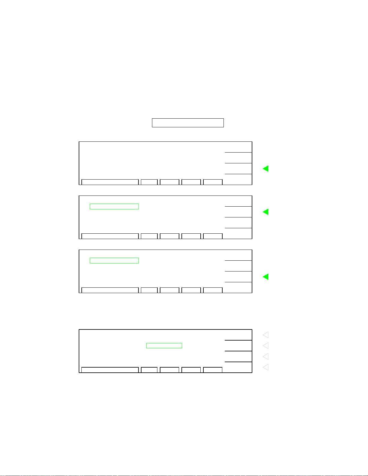
2.15.6 CHANGE PASSWORD
The Sentry Plus Series instruments have a password function for locking out the front panel so
that the instrument PRESET settings and PROGRAM function are disabled. The CHANGE
PASSWORD function applies to the initial instrument password. The password is comprised of
“A” or “B” characters and can be 1-10 characters in length. To activate the CHANGE
PASSWORD function with the instrument in STAND BY status:
•
•
•
Press [F3] = MENU
Press [F2] = DOWN until CHANGE PASSWORD is backlit.
Press [F3] = SELECT
STAND BY
MENU
MENU
•
•
PASSWORD
LOWGCSTEP 1/5M01 0.3Ω:
0.1A
1.2
Ω
0.5s
RMT ERROFSTLOCKSTAND BY
MEMORY
1
SYSTEM
2
OPTION
3
CALIBRATION
4
KEYLOCK
5
RMT ERROFSTLOCKSELECT FUNC.
PASSWORD
6
ERROR LOG
7
ABOUT
8
MEMORY
1
SYSTEM
2
RMT ERROFSTLOCKSELECT FUNC.
Display prompts ‘ USER PASSWORD’
Press [A] [A] [A] [A ] [E N T E R]
CHANGE PASSWORD
USER PASSWORD
xxxx
RMT ERROFSTLOCK1 - 10 CHAR.
PROGRAM
PRESET
MENU
MORE..
UP
DOWN
SELECT
EXIT
UP
DOWN
SELECT
EXIT
A
B:
ENTER
RETURN
F1
F2
Press F3 = "MENU"
F3
To change instrument parameters
F4
F1
Press F2 = "DOWN" to move
F2
highlighted box to PASSWORD
F3
F4
F1
F2
Press F3 = "SELECT" to enter
F3
PASSWORD function
F4
Press F1 = "A" to input password
F1
character
Press F2 = "B" to input password
F2
character
Press F3 = "ENTER" to enter
F3
whole password
Press F4 = "RETURN" to go back
F4
to MENU display
Operation Page 63 of 85
Page 64

•
•
•
•
•
PASSWORD
PASSWORD
Display prompts ‘NEW PASSWORD’
Press [B] [B] [B] [B] [ENTER]
Display prompts ‘CONFIRM’
Press [B] [B] [B] [B] [ENTER]
Display prompts ‘CHANGE PASSWORD OK’.
CHANGE PASSWORD
NEW PASSWORD
CHANGE PASSWORD
CONFIRM
:
RMT ERROFSTLOCK1 - 10 CHAR.
:
RMT ERROFSTLOCK1 - 10 CHAR.
xxxx
xxxx
A
B
ENTER
A
B
ENTER
Press F1 = "A" to input password
F1
character
Press F2 = "B" to input password
F2
character
Press F3 = "ENTER" to enter
F3
whole password
F4
Press F1 = "A" to input password
F1
character
Press F2 = "B" to input password
F2
character
Press F3 = "ENTER" to enter
F3
whole password
F4
F1
PASSWORD
•
•
CHANGE PASSWORD OK!
RMT ERROFSTLOCK
RETURN
F2
F3
Press F4 = "RETURN" to go back
F4
to MENU display
Press [F4] = RETURN to exit password function and return to MENU display.
Press [F4] = EXIT to go to STAND BY display.
Page 64 of 85 Operation
Page 65

2.15.7 ERROR LOG
The Sentry Plus Series instruments have an Error Log to track invalid remote commands. The
remote interface is not available at this time.
2.15.8 ABOUT
The Sentry Plus Series instruments have a parameter labeled ‘About’. This parameter lists the
instrument manufacturer, software version and date. To view the cont ents of ABOUT with the
instrument in STAND BY status:
•
•
•
•
Press [F3] = MENU
Press [F2] = DOWN until ABOUT is backlit.
Press [F3] = SELECT
Display lists the contents of ABOUT.
F1
F2
F3
F4
Return to MENU
ABOUT
Display
Sentry 30 Plus VERSION X.XX
COPYRIGHT (c) 2001 - 2002
QuadTech Inc.
http://www.quadtech.com
RMT ERROFSTLOCKABOUT
RETURN
Figure 2-8: ABOUT Display
Operation Page 65 of 85
Page 66

Page 67
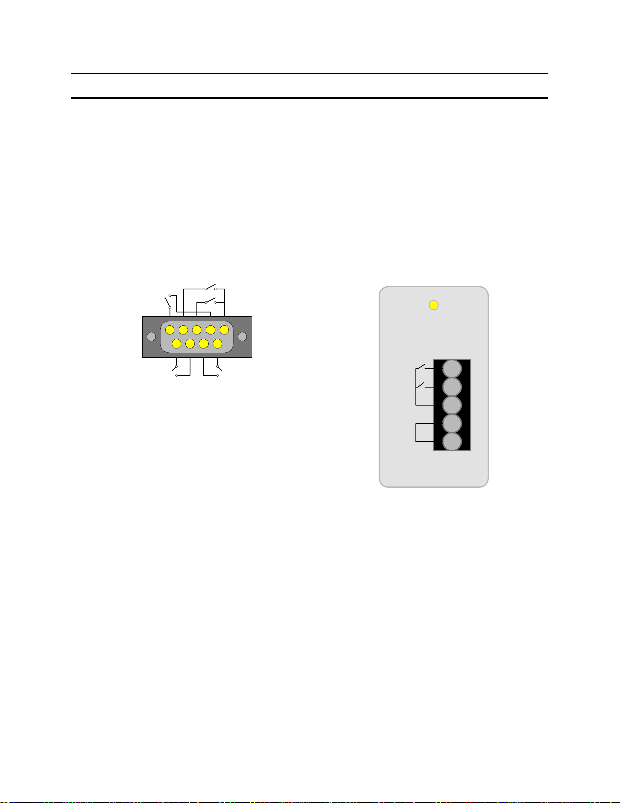
Section 3: Interface
3.1 Remote
A 9-pin D-Series remote control connector is located on the rear panel of the Sentry Plus Series
instrument. There is a black 5 screw terminal strip for the remote input signals: START,
RESET, COM and INTERLOCK. Inputs require a contact closure. Figure 3-1 illustrates the
Remote terminal strip connector and 9-pin D-Series connector.
Before connecting the instrument to its power source, the interlock function on the rear panel
remote connector (terminal strip) must be properly utilized. This is an important safety feature
for the protection of the operator. When the INT ERLOCK jumper is removed, there is no high
voltage at the OUTPUT. Therefore, to initiate a test make sure the interlock jumper is in place.
UNDER
TEST
15
69
RESET
START
FAILPASS
9-pin D-Series Remote Connector
5-screw Remote Terminal Strip
START
RESET
COM
INTER
LOCK
Figure 3-1: Sentry Plus Series Remote Connectors
The Sentry Plus Series instrument has three output signals on the rear panel. The UNDER TEST
relay is closed during a test. The PASS relay is closed when the DUT is judged GOOD. The
FAIL relay is closed when the DUT is judged NO GOOD. These relays are rated for voltage up
to 115VAC and current <100mA.
Interface Page 67 of 85
Page 68

Figures 3-2 and 3-3 illustrate possible remote control connections to the Sentry Plus Series
terminal strip. Use extreme care when usin g a remote control connection as the High Voltage
Output is being turned ON and OFF with an external signal.
START
RESET
COM
INTER
LOCK
Figure 3-2: Single Control of START or RESET
START
RESET
COM
INTER
LOCK
Figure 3-3: Continuous Control of RESET
START
RESET
COM
INTER
LOCK
Ic
COM
i
RESET
START
Ic'
i'
Photocoupler ON
20ms
Figure 3-4: Logic Components as Control Circuit
Figure 3-4 illustrates the usage of logic components (transistor, FET or couplers) as a control
≤
circuit. To use this system to control the circuit, the low signal current must be
2mA and the
input signal’s active time must be > 20ms. The relay switch in Figure 3-2 or the coupler control
in Figure 3-4 uses the component’s contact for the control action, not both. This can effectively
prevent operation interference however be observant of interference induced by measurement
settings.
START and RESET terminals have unregulated 24VDC present. To initiate a test connect the
START and COM terminals. The input time duration is approximately 20milliseconds. The
above input circuits are not isolated from other internal ci rcuits. To terminate a test connect the
RESET and COM terminals.
Page 68 of 85 Interface
Page 69

Figure 3-5 illustrates the timing diagram for the Sentry Plus Series instruments under a PASS
condition and a FAIL condition.
PASS CONDITION FAIL CONDITION
CLOSE
START
OPEN
CLOSE
UNDER
TEST
OPEN
PASS
FAIL
RESET
CLOSE
OPEN
CLOSE
OPEN
CLOSE
OPEN
180ms
180ms
0.5ms
0.5ms
COM
INTERLOCK
CLOSE
OPEN
Figure 3-5: Sentry Plus Series Timing Diagram
Interface Page 69 of 85
Page 70

3.2 G16 International Power Strip
The Sentry Plus Series instruments can be connected to the G16 International Power Strip as
illustrated in Figure 3-6 for safety testing of many European corded products.
*Australia *United Kingdom *Denmark
*North America *Norway *Finland
*Sweden *Germany *Netherlands
*Austria *Switzerland *Italy
1. Connect the three G-16 ground connectors to the Sentry Plus RTN/LOW terminal.
2. Note: there is a second RTN/LOW terminal on the rear of the Sentry instrument.
3. Connect the white banana plug to the Sentry Plus OUTPUT terminal.
4. Plug DUT’s AC power cord into corresponding module on G16 power strip.
Sentry 30 Plus Hipot Tester
STOP
START
Q
uadTech
Sentry 30 Plus AC/DC/IR Hipot Tester
F1
F2
F3
F4
F1
F2
F3
F4
Green
Lug
to
RTN
OUTPUT
White
Custom
Banana
Plug
to
HV
OUTPUT
01
CAL UPDATE
DANGERPASS FAIL
Green/
Yellow
Lug
to
RTN
or RTN
on Rear
Panel
!
CAUTION
Max 5kVAC
6kVDC
RTN/LOW
Black
Banana
Plug
to
RTN
G16 International Power Strip
QuadTech
AUSTRALIA UNITED KINGDOM DENMARK NORTH AMERICA
NORWAY FINLAND
SWEDEN
GERMANY
AUSTRIA NETHERLANDS
SWITZERLAND ITALY
Figure 3-6: G16 International Power Strip Connection to Sentry 30 Plus
Page 70 of 85 Interface
Page 71

3.3 S07 Power Entry Adapter Cable
The S07 Power Entry Adapter Cable is a 3-wire AC inlet recept acle for precise t esting of corded
products. The S07 cable is connected to the Sentry Plus Series instrument via a two-lead set.
1. Remove DUT’s power cord form its AC inlet module.
2. Plug S07 Power entry adapter into DUT’s AC inlet module.
3. Connect the white custom banana plug to the Sentry Plus OUTPUT terminal. Connect
black banana plug with retaining bracket to the Sentry Plus RTN/LOW terminal.
4. For GC test, connect GC Lead (700100) to rear Sentry Cont Check terminal and metal on
case of DUT.
Figure 3-7 illustrates this connection of the S07 cable to a Sentry 30 Plus instrument.
REAR Sentry Plus Inst rument
WARNING: FOR CONTINUED PROTECTION
AGAINST F IRE HAZARD, REPLAC E ONLY WITH
THE SAME TYPE AND RATING OF FUSE AS
!
SPECIFIED FOR THE LINE VOLTAGE BEING
UTILIZED.
CAUTION: NO OPERATOR SERVICEABL E PARTS
INSIDE. REFER SERVICING TO QU ALIFIED
!
PERSONNEL.
POLLUTION D EGREE 2
INSTALLATION CATEGORY II
VOLTAGE SELECTOR
MODEL NO.
SERIAL NO.
HIGH VOLTAGE
Max 5kVAC/6kVDC
HV OUTPUT
90V - 110V ~
108V - 132V ~
198V - 242V ~
216V - 250V ~
RTN/LOW
15
69
3.15AT
250V
1.6AT
250V
CONT. CHECK OPTION
100V/120V/220V/240V~
50/60Hz 300W MAX
START
RESET
COM
INTER
LOCK
FAN 50o C AUTO ON/OFF
Ground Continuity Connection
4
DUT
(Monitor)
STOP
START
Q
01
Remove DUT's power
1
cord
uadTech
Sentry 30 Plus AC/DC/IR Hipot Tester
CAL UPDATE
DANGERPASS FAIL
from AC inlet module
Plug S07 Adapter into
2
DUT's AC inlet module
Figure 3-7: S07 Power Entry Adapter Cable
!
CAUTION
Max 5kVAC
6kVDC
Black
Banana
Plug with
Retaining
Bracket
to
RTN/LOW
S07
Power Entry
Adapter
F1
F2
F3
F4
RTN/LOW
3
Hipot
Connection
F1
F2
F3
F4
OUTPUT
Custom
White
Banana
Plug
to
OUTPUT
Interface Page 71 of 85
Page 72

3.4 S03 Corded Product Adapter (115V)
The S03 Corded Product Adapter is a 3-prong electrical outlet box to facilitate testing of corded
products. The S03 cable is connected to the Sentry Plus Series instrument via a two-lead set.
1. Connect the black banana plug to the Sentry Plus RTN/LOW.
2. Connect the white banana plug to the Sentry Plus OUTPUT terminal.
Plug the DUT’s 3-wire power cord into the S03 corded product adapter.
3.
4.
For GC test, connect GC Lead (700100) to rear Sentry Cont Check terminal and metal on
case of DUT.
Figure 3-8 illustrates this connection of the S03 cable to a Sentry 30 Plus instrument.
WARNING: FOR CONTINUED PROTECTION
AGAINST FIRE HAZARD, REPLACE ONLY WITH
THE SAME TYPE AND RATING OF FUSE AS
!
SPECIFIED FOR THE LINE VOLTAGE BEING
UTILIZED.
CAUTION: NO OPER ATOR SERVICEABLE PARTS
INSIDE. REFER SERVICING TO QUALIFIED
!
PERSONNEL.
POLLUTION DEGREE 2
INSTALL ATION CATEGORY II
VOLTAGE SELECTOR
MODEL NO.
SERIAL NO.
HIGH VOLTAGE
Max 5kVAC/6kVDC
HV OUTPUT
90V - 110V ~
108V - 132V ~
198V - 242V ~
216V - 250V ~
RTN/LOW
15
69
3.15AT
250V
1.6AT
250V
CONT. CHECK OPTION
100V/120V/220V/240V~
50/60Hz 300W MAX
START
RESET
COM
INTER
LOCK
FAN 50o C AUTO ON/OFF
Ground Continuity Connection
4
STOP
START
Q
uadTech
01
Sentry 30 Plus AC/DC/IR Hipot Tester
CAL UPDATE
3
DANGERPASS FAIL
QuadTech
!
CAUTION
Max 5kVAC
1
6kVDC
Black
Banana
Plug
to
RTN/LOW
F1
F2
F3
F4
RTN/LOW
Hipot
Connection
DUT plugged into
F1
F2
F3
F4
OUTPUT
Custom
White
Banana
Plug
to
OUTPUT
2
S03 Adapter
20A 125V
DO NOT TOUCH WHILE UNDER TEST
MAX. VOLTAGE
5kVAC
6kVDC
DUT (Monitor)
Product Adapter
Figure 3-8: S03 Corded Product Adapter
Page 72 of 85 Interface
S03 Corded
Page 73

3.5 S05 Foot Switch
The S05 Foot Switch provides hands-free remote testing capability. The spade leads on the S05
Foot Switch are connected (screwed) to the terminal strip on the rear panel of the Sentry Plus
Series instrument.
1. Connect (screw) the white wire/spade connector to the START terminal.
2. Connect (screw) the red wire/s pade connector to the COM terminal.
Figure 3-9 illustrates this connection of the S05 Foot Switch to a Sentry 30 Plus instrument.
Terminal Strip rear of Sentry 30 Plus
WARNING: FOR CONTINUED PROTECTION
AGAINST FIRE HAZAR D, REPLACE ONLY WITH
THE SAME TYPE AND RATING OF FUSE AS
!
SPECIFIED FOR THE LINE VOLTAGE BEING
UTILIZED.
CAUTION: NO O PERATOR SERVICEABLE PARTS
INSIDE. REFER SERVICING TO QUALIFIED
!
PERSONNEL.
POLLUTION DEGREE 2
INSTALLA TION CATEGORY II
VOLTAGE SELECTOR
MODEL NO.
SERIAL NO.
HIGH VOLTAGE
Max 5kVAC/6kVDC
HV OUTPUT
90V - 110V ~
108V - 132V ~
198V - 242V ~
216V - 250V ~
RTN/LOW
15
69
3.15AT
250V
1.6AT
250V
CONT. CHECK OPTION
100V/120V/220V/240V~
50/60Hz 300W MAX
START
RESET
COM
INTER
LOCK
FAN 50o C AUTO ON/OFF
White
Wire &
Spade
to
Terminal
Strip:
START
Red
Wire &
Spade
to
Terminal
Strip:
COM
S05 Foot Switch
Figure 3-9: S05 Foot Switch
Interface Page 73 of 85
Page 74

3.6 S08 Gun Probe
The S08 Gun Probe provides fast testing capability with pinpoint control. Use the black lead o f
the S02 Lead Set with the S08 Gun Probe.
1. Connect the S02 black banana plug to the Sentry Plus RTN/LOW terminal.
2. Connect the S02 black alligator clip to the low side of the DUT.
3. Connect the white banana plug to the Sentry Plus OUTPUT terminal.
Figure 3-10 illustrates this connection of the S08 probe to a Sentry 30 Plus unit.
STOP
START
Q
uadTech
Sentry 30 Plus AC/DC/IR Hipot Tester
F1
F2
F3
F4
F1
F2
F3
F4
01
CAL UPDATE
DANGERPASS FAIL
!
Use S02 Lead:
Black Banana Plug
1
to RTN/LOW
CAUTION
Max 5kVAC
RTN/LOW
6kVDC
S08
GUN PROBE
OUTPUT
3
Custom
White
Banana
Plug
to
OUTPUT
++++
Rack
of
DUTs
----
2
Figure 3-10: S08 Gun Probe connected to Sentry 30 Plus Hipot Tester
Page 74 of 85 Interface
Page 75
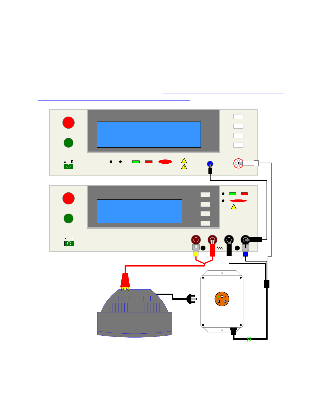
3.7 S50 Plus Ground Bond Tester
The Sentry Plus Series instrument can be connected to the Sentry 50 Plus Ground Bond Tester
for high current ground testing between chassis and power cord ground. The output current is
programmable from 1A to 30A AC in 0.01A increments and resistance can be measur ed over the
range 0.1mΩ to 510mΩ. The rear panels of the Sentry Plus Series instrument and Sentry 50 Plus
instrument are connected via the S15 9-pin interconnection cable. Figure 3-11 illustrates the
front panel connections of the two instruments. NOTE: GFI must be turned OFF on the Sentry
Plus unit when it is used with the Sentry 50 Plus instrument.
STOP
START
01
l
STOP
START
01
l
S50 Plus Ground Bond Tester
Q
uadTech
CAL UPDATE
Q
uadTech
G15
Banana to
Alligator
Cable
Sentry 30 Plus AC/DC/IR Hipot Tester
DANGERPASS FAIL
Sentry 50 Plus GROUND BOND TESTER
Banana/Banana CableSentry 30 Plus AC/DC/IR Hipot Tester
plugged into
!
F1
F2
F3
F4
DUT
G13
CAUTION
Max 5kVAC
6kVDC
DRIVE SENSESENSE
F1
F2
F3
F4
RTN/LOW
F1
F2
F3
F4
+
QuadTech
F1
F2
F3
F4
OUTPUT
PASS FAIL
DANGER
HIGH
!
CURRENT
RTN/LOW
-
DUT
(Monitor)
125
20A
V
DO NOT TOUCH WHILE
UNDER TEST
MAX.
VOLTAGE
5kVAC
6kVDC
G13
Corded
Product
Adaptor
Figure 3-11: Guardian 1030S & Sentry 50 Plus Connection
Interface Page 75 of 85
Page 76

Page 77

Section 4: Service & Calibration
4.1 General
Our warranty (at the front of this manual) attests to the quality of materials and workmanship in
out products. If malfunction should be suspected, or other information desired, applications
engineers are available for technical assistance. Applications assistance is avai lable in the U.S.
by calling (978) 461-2100 and asking for Applications Support. For support outside of the
United States please contact your local QuadTech Distributor. Service/Calibration and
Distributor information is also available online.
4.2 Instrument Return
Before returning an instrum ent to QuadTech for service please call our Customer Care Center
(CCC) at 800-253-1230 for Return Material Authorization (RMA). It will be necessary to
include a Purchase Order Number to insure expedient processin g, although units found to be in
warranty will be repaired at no-charge. For any questions on repair costs or shipping instructions
please contact our CCC Department at the afore-mentioned number. To safeguard an instrument
during storage and shipping, please use packaging that is adequate to protect it from damage, i.e.
equivalent to the original packagin g, and mark the box “Delicat e Electroni c Instrument”. R eturn
material should be sent freight prepaid to:
QuadTech, Inc.
5 Clock Tower Place, 210 East
Maynard, Massachusetts 01754
Attention: RMA#
Shipments sent collect cannot be accepted.
4.3 Calibration
Calibration of the Sentry Plus Series instruments is recommended on an annual basis. If the unit
is returned to QuadTech for factory calibration, refer to paragraph 4.2 for RMA and shipping
instructions. Using the calibration procedure in paragraph 4.3.1, the Sentry Plus Series
instrument may be calibrated by a qualified service person IF traceable calibration equipment
and standards are available. The instrument should be powered up for a minimum of 30
minutes prior to calibration to ensure maximum stability.
Service & Calibration Page 77 of 85
Page 78
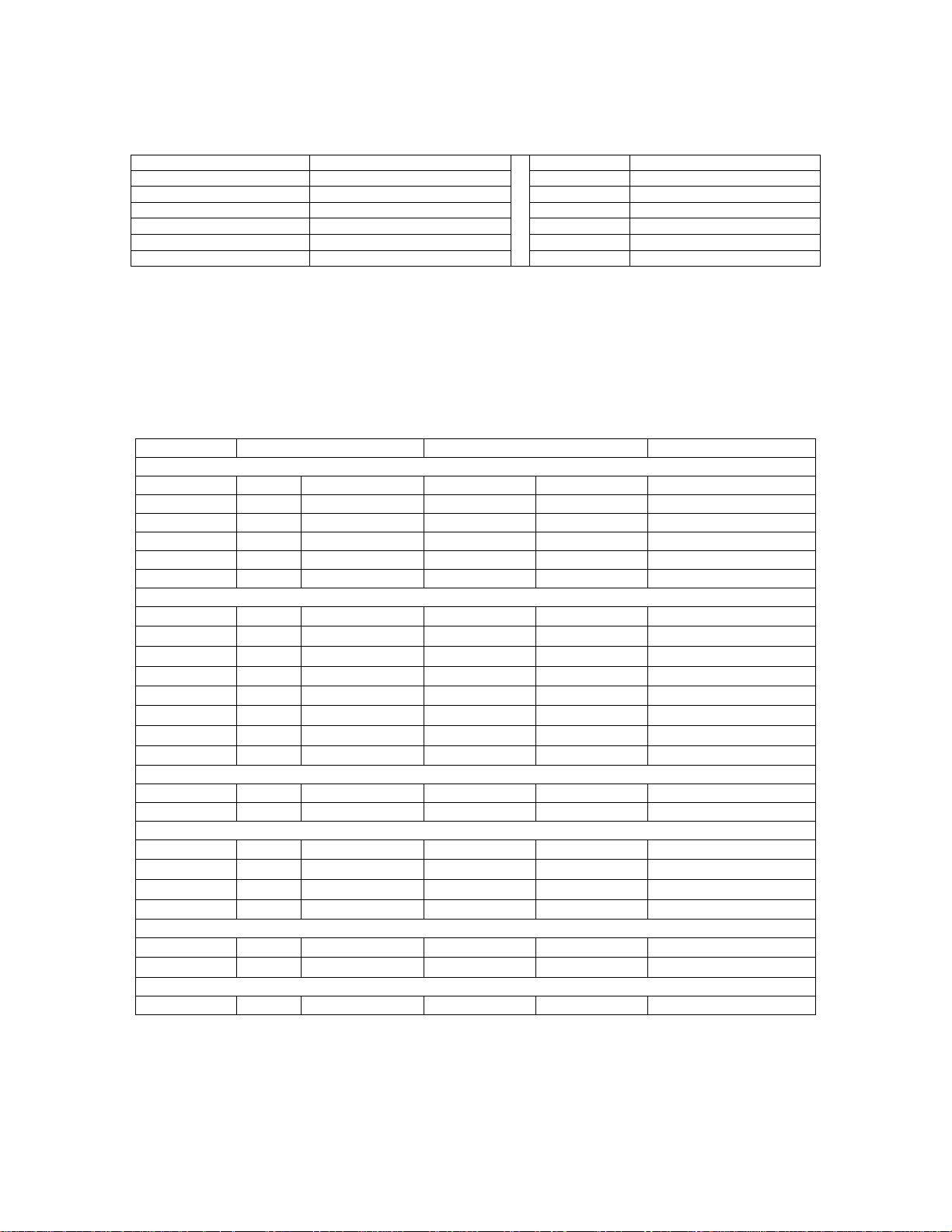
Table 4-1: Calibration Equipment
Equipment Requirements Equipment Requirements
AC/DC High Voltage Volt meter Measure: 0 to 6kV, 0.1% accuracy
AC/DC Current Meter Measure: 0 to 40mA, 0.1% accuracy
1GΩ Resistance Standard
100MΩ Resistance Standard
10MΩ Resistance Standard
500kΩ Resistance Standard
250V
500V
1200V, 0.12m A, 0. 25W; 500V; 1kV
1200V, 2.4mA, 0.25W
250kΩ Res. Std
100kΩ Res. Std
80kΩ Res. Std
1Ω Resistor
3Ω Resistor
1200V, 5mA, 5W ; 1250V 7mA
400V, 4mA, 50W; 1200V 12mA
1200V, 15mA, 100W
0.1A
0.1A
4.3.1 Calibration Parameters
Table 4-2 contains the calibration parameters for the Sentry Plus Series instruments. All tests
points are not required for each of the instruments (10 Plus, 20 Plus & 30 Plus).
Table 4-2: Calibration Parameters
PRODUCT TEST RANGE CAL. POINT
Voltage Calibration
10/20/30 CAL ACV 5kV OFST 0.050kV
10/20/30 CAL ACV 5kV FULL 4.000kV
20/30 CAL DCV 6kV OFST 0.050kV
20/30 CAL DCV 6kV FULL 4.000kV
30 CAL IR 1kV OFST 0.050kV
30 CAL IR 1kV FULL 1.000kV
Current Calibration
10/20/30 CAL ACA 3mA OFST
10/20/30 CAL ACA 3mA FULL
10/20/30 CAL ACA 15mA OFST
10/20/30 CAL ACA 15mA FULL
20/30 CAL DCA 3mA OFST
20/30 CAL DCA 3mA FULL
20/30 CAL DCA 5mA OFST
20/30 CAL DCA 5mA FULL
0.12mA / 10MΩ
2.4mA / 500kΩ
2.4mA / 500kΩ
12mA / 100kΩ
0.12mA / 10MΩ
2.4mA / 500kΩ
2.4mA / 500kΩ
4.8mA / 250kΩ
WAC & WDC Arcing Calibratio n
10/20/30 CAL AC ARC 15mA Arc 7.00mA
20/30 CAL DC ARC 5mA Arc 5.00mA
IR Resistance Calibration
30 CAL IRR Range1
30 CAL IRR Range2
30 CAL IRR Range3
30 CAL IRR Range4
1000MΩ
100MΩ
10MΩ
10MΩ
Range 1
Range 2
Range 3
Range 4
1000M = 1.00GΩ
100.0MΩ
10.0MΩ
10.0MΩ
Ground Continuity Calibration
10/20/30 CAL GC
10/20/30 CAL GC
1Ω
3Ω
OFST
FULL
1Ω
3Ω
Contrast Calibration
10/20/30 CAL CONTRAST 11 11 13
Page 78 of 85 Service & Calibration
Page 79

4.3.2 Enable Calibration
The instrument should be powered up for a minimu m of 30 minutes prior to calibration to
ensure maximum stability. With the Sentry Plus Series instrument in standby status ([STOP]
button previously pressed and no warning lights flashing) remove the Calibration seal over the
hole labeled “CAL’ on the front panel and push the recessed switch to the IN position.
The unit is in STAND BY status.
Press [F3] = MENU.
Press [F2] = DOWN three times until CALIBRATION is highlighted (backlit).
Press [F3] = SELECT to choose calibration function.
Display will prompt for a password.
Press [A] [A] [A] [B ] [ENTER]
Cal Step 1: ‘ACV 5kV Offset (50V)’ is displayed on the screen.
NOTE
The ‘Calibration is OFF’ display may occur if the CAL recessed switch has not been pressed IN
prior to entering Calibration function.
Figure 4-1: Calibration Password Prompt
NOTE:
When in the Calibration Routine:
Pressing [UP] or [DOWN] scrolls through the calibration steps.
Pressing [START] initiates the calibration of the particular step
Pressing [INC.] or [DEC.] adjusts the Standard Value
Pressing [ENTER] accepts the calibration value.
Pressing [STOP] completes calibration of the particular step.
Service & Calibration Page 79 of 85
Page 80

4.3.3 AC Voltage Calibration
Connect the OUTPUT terminal of the Sentry Plus Series unit to the input terminal of the AC/DC
high voltage meter. Connect the RTN/LOW terminal of the Sentry Plus to the GND terminal of
the voltmeter. Set the voltmeter to AC and 2kV range.
Cal Step 1: ‘ACV 5kV Offset (50V)’
Press [STOP] to return instrument to steady state.
Press [START] to get offset value.
Press [F1] = INC or [F2] = DEC until the Sentry Plus display reads the same as the voltmeter.
Press [ENTER] to accept reading.
Sentry Plus reverts to “ACV Offset” display (incorporating new cal value).
Press [F1] = UP to go to Cal Step 2: ‘ACV 5kV Full (4kV)’. Change voltmeter range to 20kV.
Press [STOP] to return instrument to steady state.
Press [START] to get full value
Press [F1] = INC or [F2] = DEC until the Sentry Plus display reads the same as the voltmeter.
Press [ENTER] to accept reading.
Sentry Plus reverts to “ACV Full” display (incorporating new cal value).
4.3.4 DC Voltage Calibration (DCV)
Change the setting on the Valhalla voltmeter to DC and 2kV range. DC calibration is applicable
to the Sentry 20 Plus and Sentry 30 Plus instruments.
Press [F1] = UP to go to Cal Step 3: ‘DCV 6kV Offset (50V)’.
Press [STOP] to return instrument to steady state.
Press [START] to get offset value.
Press [F1] = INC or [F2] = DEC until the Sentry Plus display reads the same as the voltmeter.
Press [ENTER] to accept reading.
Sentry Plus reverts to “DCV Offset” display (incorporating new cal value).
Press [F1] = UP to go to Cal Step 4: ‘DCV 6kV Full (4kV)’. Change voltmeter range to 20kV.
Press [STOP] to return instrument to steady state.
Press [START] to get full value.
Press [F1] = INC or [F2] = DEC until the Sentry Plus display reads the same as the voltmeter.
Press [ENTER] to accept reading.
Sentry Plus reverts to “DCV Full” display (incorporating new cal value).
Page 80 of 85 Service & Calibration
Page 81

4.3.5 IR Voltage Calibration (IRV)
Keep the setting on the Valhalla voltmeter at DC and 2kV range. IR calibration is applicable to
the Sentry 30 Plus instrument.
Press [F1] = UP to go to Cal Step 5: ‘IRV 1kV Offset (50V)’.
Press [STOP] to return instrument to steady state.
Press [START] to get offset value.
Press [F1] = INC or [F2] = DEC until the Sentry Plus display reads the same as the voltmeter.
Press [ENTER] to accept reading.
Sentry Plus reverts to “IRV Offset” display (incorporating new cal value).
Press [F1] = UP to go to Cal Step 6: ‘IRV 1kV Full (1kV)’. Change voltmeter range to 20kV.
Press [STOP] to return instrument to steady state.
Press [START] to get full value.
Press [F1] = INC or [F2] = DEC until the Sentry Plus display reads the same as the voltmeter.
Press [ENTER] to accept reading.
Sentry Plus reverts to “IRV Full” display (incorporating new cal value).
Service & Calibration Page 81 of 85
Page 82

4.3.6 AC Current Calibration (ACA)
Connect the OUTPUT terminal of the Sentry Plus Series instrument to a resistance box or
resistance standard. Connect an AC/DC current meter in series between the resistance load
(box/standard) and the RTN/LOW terminal of the Sentry Plus instrument. Table 4-3 lists the
resistance loads necessary for the current calibration steps.
Table 4-3: Resistance Loads
Mode Step # Voltage Calibration
Point
ACA CAL 7 1200 V 0.12mA
ACA CAL 8 1200 V 2.4mA full
ACA CAL9 1200 V 2.4mA
ACA CAL 10 1200 V 12mA
DCA CAL 11 1200 V 0.12mA
DCA CAL 12 1200 V 2.4mA full
DCA CAL 13 1200 V 2.4mA
DCA CAL 14 1200 V 4.8mA
Resistance
(Load)
10MΩ
500kΩ
500kΩ
100kΩ
10MΩ
500kΩ
500kΩ
250kΩ
Press [F1] = UP to go to Cal Step 7: ‘ACA 3mA Offset (0.12mA)’.
Press [STOP] to return instrument to steady state.
Press [START] to get offset value.
Press [F1] = INC or [F2] = DEC until the SPlus display reads the same as the current meter.
Press [ENTER] to accept reading.
Sentry Plus reverts to “ACA 3mA Offset” display (incorporating the new cal value).
Press [F1] = UP to go to Cal Step 8: ‘ACA 3mA Full (2.4mA)’.
Press [STOP] to return instrument to steady state.
Press [START] to get full value.
Press [F1] = INC or [F2] = DEC until the SPlus display reads the same as the current meter.
Press [ENTER] to accept reading.
Sentry Plus reverts to “ACA 3mA Full” display (incorporating the new cal value).
Press [F1] = UP to go to Cal Step 9: ‘ACA 15mA Offset (2.4mA)’.
Press [STOP] to return instrument to steady state.
Press [START] to get offset value.
Press [F1] = INC or [F2] = DEC until the SPlus display reads the same as the current meter.
Press [ENTER] to accept reading.
Sentry Plus reverts to “ACA 30mA Offset” display (incorporating the new cal value).
Press [F1] = UP to go to Cal Step 10: ‘ACA 15mA Full (12mA)’.
Press [STOP] to return instrument to steady state.
Press [START] to get full value.
Press [F1] = INC or [F2] = DEC until the SPlus display reads the same as the current meter.
Press [ENTER] to accept reading.
Sentry Plus reverts to “ACA 30mA Full” display (incorporating the new cal value).
Page 82 of 85 Service & Calibration
Page 83

4.3.7 DC Current Calibration
Connect the OUTPUT terminal of the Sentry Plus Series instrument to a resistance box or
resistance standard. Connect an AC/DC current meter in series between the resistance load
(box/standard) and the RTN/LOW terminal of the Sentry Plus instrument.
Press [F1] = UP to go to Cal Step 11: ‘DCA 3mA Offset (0.12mA)’.
Press [STOP] to return instrument to steady state.
Press [START] to get offset value.
Press [F1] = INC or [F2] = DEC until the SPlus display reads the same as the current meter.
Press [ENTER] to accept reading.
Sentry Plus reverts to “DCA 3mA Offset” display (incorporating the new cal value).
Press [F1] = UP to go to Cal Step 12: ‘DCA 3mA Full (2.5mA)’.
Press [STOP] to return instrument to steady state.
Press [START] to get full value.
Press [F1] = INC or [F2] = DEC until the SPlus display reads the same as the current meter.
Press [ENTER] to accept reading.
Sentry Plus reverts to “DCA 3mA Full” display (incorporating the new cal value).
Press [F1] = UP to go to Cal Step 13: ‘DCA 5mA Offset (2.4mA)’.
Press [STOP] to return instrument to steady state.
Press [START] to get offset value.
Press [F1] = INC or [F2] = DEC until the SPlus display reads the same as the current meter.
Press [ENTER] to accept reading.
Sentry Plus reverts to “DCA 15mA Offset” display (incorporating the new cal value).
Press [F1] = UP to go to Cal Step 14: ‘DCA 5mA Full (4.8mA)’.
Press [STOP] to return instrument to steady state.
Press [START] to get full value.
Press [F1] = INC or [F2] = DEC until the SPlus display reads the same as the current meter.
Press [ENTER] to accept reading.
Sentry Plus reverts to “DCA 15mA Full” display (incorporating the new cal value).
Service & Calibration Page 83 of 85
Page 84

4.3.8 ARC Calibration
ARC calibration is part of the calibration routine but it is not performed on the Sentry Plus
instruments. ARC Calibration is set at the factory. To by-pass these two steps:
Press [F1] = UP to go to Cal Step 15: ‘AC ARC 15mA (7mA)’. BY-PASS
Press [F1] = UP to go to Cal Step 16: ‘DC ARC 5mA (5mA)’. BY-PASS
4.3.9 IR Resistor Calibration (IRR)
Connect the resistance load (per Table 4-2) between the Sentry Plus instrument’s OUTPUT
terminal and RTN/LOW terminal.
Press [F1] = UP to go to Cal Step 17: ‘IRR Range1 (1GΩ)’.
Press [STOP] to return instrument to steady state.
Press [START] to get range1 value.
Press [F1] = INC or [F2] = DEC until the Splus display reads the same as certified load value.
Press [ENTER] to accept reading.
Sentry Plus reverts to “IRR Range1” display (incorporating the new cal value).
Press [F1] = UP to go to Cal Step 18: ‘IRR Range2 (100MΩ)’.
Press [STOP] to return instrument to steady state.
Press [START] to get range2 value.
Press [F1] = INC or [F2] = DEC until the SPlus display reads the same as certified load value.
Press [ENTER] to accept reading.
Sentry Plus reverts to “IRR Range2” display (incorporating the new cal value).
Press [F1] = UP to go to Cal Step 19: ‘IRR Range3 (10MΩ)’.
Press [STOP] to return instrument to steady state.
Press [START] to get range3 value.
Press [F1] = INC or [F2] = DEC until the SPlus display reads the same as certified load value.
Press [ENTER] to accept reading.
Sentry Plus reverts to “IRR Range3” display (incorporating the new cal value).
Ω
Press [F1] = UP to go to Cal Step 20: ‘IRR Range4 (10M
)’.
Press [STOP] to return instrument to steady state.
Press [START] to get range4 value.
Press [F1] = INC or [F2] = DEC until the SPlus display reads the same as certified load value.
Press [ENTER] to accept reading.
Sentry Plus reverts to “IRR Range4” display (incorporating the new cal value).
Page 84 of 85 Service & Calibration
Page 85

4.3.10 Ground Continuity Calibration
GC 5
ΩΩΩΩ
Offset (1
ΩΩΩΩ
)
Connect a 1Ω load resistor between the Sentry Plus instrument’s rear panel RTN/LOW terminal
and Ground Continuity Option terminal.
Press [F1] = UP to go to Cal Step 21: ‘GC 5Ω Offset (1Ω)’.
Press [STOP] to return instrument to steady state.
Press [START] to get offset value.
Press [F1] = INC or [F2] = DEC until the Splus display reads the same as certified load value.
Press [ENTER] to accept reading.
Sentry Plus reverts to “GC 5Ω Offset” display (incorporating the new cal value).
GC 5
ΩΩΩΩ
Full (3
ΩΩΩΩ
)
Connect a 3Ω load resistor between the Sentry Plus instrument’s rear panel RTN/LOW terminal
and Ground Continuity Option terminal.
Press [F1] = UP to go to Cal Step 22: ‘GC 5Ω Full (3Ω)’.
Press [STOP] to return instrument to steady state.
Press [START] to get full value.
Press [F1] = INC or [F2] = DEC until the SPlus display reads the same as certified load value.
Press [ENTER] to accept reading.
Sentry Plus reverts to “GC 5Ω Full” display (incorporating the new cal value).
4.3.11 Contrast Calibration
This calibration step is by-passed. If setup is selected, the display contrast will be set to a level
of 7. Display contrast can be adjusted as specified in paragraph 2.15.2.1.
4.3.12 Finalize Calibration
When all calibration steps are complete:
Press [F4] = EXIT
Release the [CAL] enable switch to the OUT position using the tip of a small screwdriver.
1. Press [F2] = DOWN three times.
2. Press [F3] = SELECT
3. Display prompts: ‘PASSWORD’.
4. Press [A] [A] [A] [A] [ENTER]
5. Display prompts: ‘Select Software Calibration?’
6. Press [F1] = ON to set Calibration Values ON.
Service & Calibration Page 85 of 85
 Loading...