

Page 1

Guardian 5000
AC/DC/IR/GC Safety Analyzer
Instruction Manual
Form 150206/B3
©QuadTech, Inc., 1996
5 Clock Tower Place, 210 East
Maynard, Massachusetts, U.S.A. 01754-2530
November, 1999
Tel. 978-461-2100
800-253-1230 (Sales & Service)
Fax. 978-461-4295
Email: sales@quadtech.com
Web site: http://www.quadtech.com
The material in this manual is for informational purposes only and is subject to change,
without notice. QuadTech assumes no responsibility for any error or for consequential
damages that may result from the misinterpretation of any procedures in this publication.
IEC417
Symbol
information to prevent injury or equipment damage
!
on equipment signifies that the manual contains
Page 2

ii
Page 3

Contents
Warranty ...........................................................................................................v
Specifications ...........................................................................................................vii
Introduction - Section 1
1.1 Unpacking and Inspection.............................................................................1-1
1.1 Product Overview..........................................................................................1-1
1.3 Front Panel Description.................................................................................1-2
1.4 Rear Panel Description..................................................................................1-6
1.5 Accessories Included.....................................................................................1-7
1.6 Accessories/Options Available......................................................................1-7
1.7 Power Requirements......................................................................................1-8
Operation - Section 2
2.1 Startup ...........................................................................................................2-1
2.2 Instrument Zeroing/Offset.............................................................................2-1
2.3 Connection to Device Under Test .................................................................2-3
2.4 Measurement Procedure................................................................................2-6
2.5 Programming Test Modes .............................................................................2-8
2.6 Programming Hipot Test...............................................................................2-10
2.7 Programming Insulation Resistance (IR) Test ..............................................2-12
2.8 Programming Ground Continuity Test..........................................................2-14
2.9 Initial Parameter Setting................................................................................2-16
2.10 Front Panel Lockout......................................................................................2-18
2.11 Software Version Display..............................................................................2-18
2.12 Clear Setup Memory......................................................................................2-18
Input/Output Interfaces - Section 3
3.1 Remote...........................................................................................................3-1
3.2 IEEE-488 Interface........................................................................................3-3
3.2.1 Description ........................................................................................3-3
3.2.2 Interface Commands..........................................................................3-4
3.2.2.1 Listener Functions..............................................................3-5
3.3.2.2 Talker Functions....................................................................3-9
3.2.3 Sample QuickBASIC Program..........................................................3-11
3.3 Scanner Interface...........................................................................................3-14
3.3.1 Scanner Accessories..........................................................................3-14
3.3.2 Scanner Card Installation ..................................................................3-14
3.3.3 Scanner Connections.........................................................................3-15
3.3.4 Scanner Programming.......................................................................3-17
3.4 G16 International Power Strip.......................................................................3-19
iii
Page 4

Contents Continued
Maintenance/Calibration - Section 4
4.1 General ..........................................................................................................4-1
4.2 Instrument Return..........................................................................................4-1
4.3 Calibration.....................................................................................................4-1
4.3.1 Calibration Procedure........................................................................4-2
4.3.2 AC Voltage Calibration.....................................................................4-3
4.3.3 DC Voltage Calibration.....................................................................4-4
4.3.4 IR Voltage Calibration ......................................................................4-4
4.3.5 AC Current Calibration .....................................................................4-5
4.3.6 DC Current Calibration .....................................................................4-6
4.3.7 GC Calibration...................................................................................4-7
4.3.8 Finalize Calibration...........................................................................4-8
iv
Page 5

Warranty
echuad
T
QuadTech warrants that Products are free from defects in material and workmanship and,
when properly used, will perform in accordance with QuadTech's applicable published
specifications. If within one (1) year after original shipment it is found not to meet this
standard, it will be repaired, or at the option of QuadTech, replaced at no charge when
returned to a QuadTech service facility.
Changes in the Product not approved by QuadTech shall void this warranty.
QuadTech shall not be liable for any indirect, special or consequential damages, even if
notice has been given of the possibility of such damages.
This warranty is in lieu of all other warranties, expressed or implied, including, but not
limited to any implied warranty or merchantability or fitness for a particular purpose.
SERVICE POLICY
QuadTech policy is to maintain product repair capability for a period of at least five (5) years
after original shipment and to make this capability available at the then prevailing schedule of
charges.
v
Page 6

Specifications
Dielectric Strength
Output Voltage: Range: • 0.1 to 5 KV AC, in 10V/steps, 50 - 600Hz
Accuracy: +/- (1% of reading + 5 counts)
Regulation: <1% + 5V, rated load
Breakdown: Detection:
Leakage Current: Accuracy: +/- (1.5% + 5 counts), unspecified 0.01 - 0.3mA
Test Time: Ramp: 0.1 to 99.9sec (+/-20ms)
Hold: 0.1 to 999sec (+/-20ms)
Insulation Resistance
Measurements: Range: 10MΩ - 10GΩ
Test Voltage: 100 - 1000V DC
Accuracy: Measurement: +/- 5% ≥ 500V, 10MΩ - 1GΩ
+/- 15% ≥ 500V, 1GΩ - 10GΩ
+/- 10%<500V, 1 - 200MΩ
+/- 15%<200V, 200MΩ - 1GΩ
Voltage: +/- (1% of setting + 5 counts)
Measure Time: 0.1 - 999sec (+/-20ms)
Limit Delay: 0.3 - 99.9sec (+/-20ms)
Voltage
• 0.1 to 6 KV DC, in 10V/steps
• Imax: 0.3 - 40mA AC, 0.3 - 20mA DC
• ∆I: 0.5 to 40mA, ≤ 20µsec
1000V
500V
100V
vi
10M>
20M 50M>>
Specification Range
Resistance
>>>500M 1G 2G
Page 7

Specifications Continued
Ground Continuity
Output Current:Range: 1.0 to 30.0A AC, setting 0.1A/step
Accuracy: +/- (1% of setting + 0.3A)
+/- (1% of reading + 3 counts)
Frequency: 50 or 60Hz, 6 to 15V
Resistance: Range: 0 - 500.0mΩ, 4 digits, Hi Limit
Accuracy: +/- (1% of reading + 3 counts)
Offset Function: 0 to 100mohm offset, user selectable
Test Time: 0.5 - 999sec (+/-20ms)
Current
30A
Specification Range
10A
1A
Resistance
>> >>
100m 150m
500m10m
General
Safety Features: Fast Cutoff (<0.4msec), Fast Discharge, Panel Lock
Setup Storage: 50 Memory Groups
Remote Control: Remote start & reset, Go/NoGo output, IEEE-488 Intf.
Pass/Fail: Display indication & alarm
Mechanical: Bench mount
Dimensions: (w x h x d):17x8.5x22in (430x215x550mm)
Weight: 50 lbs (23kg) net, 60 lbs (27kg) shipping
Environmental: Meets MIL-T-28800E, Type 3, Class 5
Operating: 0 to + 45o C
Humidity: <75%
Storage: - 10 to + 60o C
Power:
• 115 V/230V +/- 10% • 47 - 63Hz • 650W max
Supplied: • Instruction Manual • Power Cable
• Calibration Certificate • Test Leads
Ordering
Information:
Description Catalog No.
AC/DC/IR/GC Safety Analyzer Guardian 5000
vii
Page 8

Page 9

Section 1 Introduction
1.1 Unpacking and Inspection
Inspect the shipping carton before opening, if damaged contact the carriers agent
immediately. Inspect the instrument for any damage. If the instrument appears damaged or
fails to meet specifications notify QuadTech (refer to instruction manual front cover) or its
local representative. Retain the shipping carton and packing material for future use such as
returning for recalibration or service.
1.2 Product Overview
The Guardian 5000 Safety Analyzer combines four critical safety tests into a single
instrument, these being AC hipot, DC hipot, insulation resistance measurements and
ground continuity test. The hipot test can be programmed over a voltage range of 0.1 to
5KV AC and 0.5 to 6KV DC with a min/max leakage current detection range of 300µA to
40mA AC and 20mA DC. Insulation resistance measurements are possible to 10GΩ at
programmable DC test voltages between 100 and 1000V. A ground continuity test to 30A
AC is also possible. The instrument comes standard with internal storage of up to 50 memory
groups and an IEEE-488.2 interface for remote control operation and communication with
other instrumentation.
Figure 1-1
Guardian 5000
Introduction 1-1
Page 10

1.3 Front Panel Description
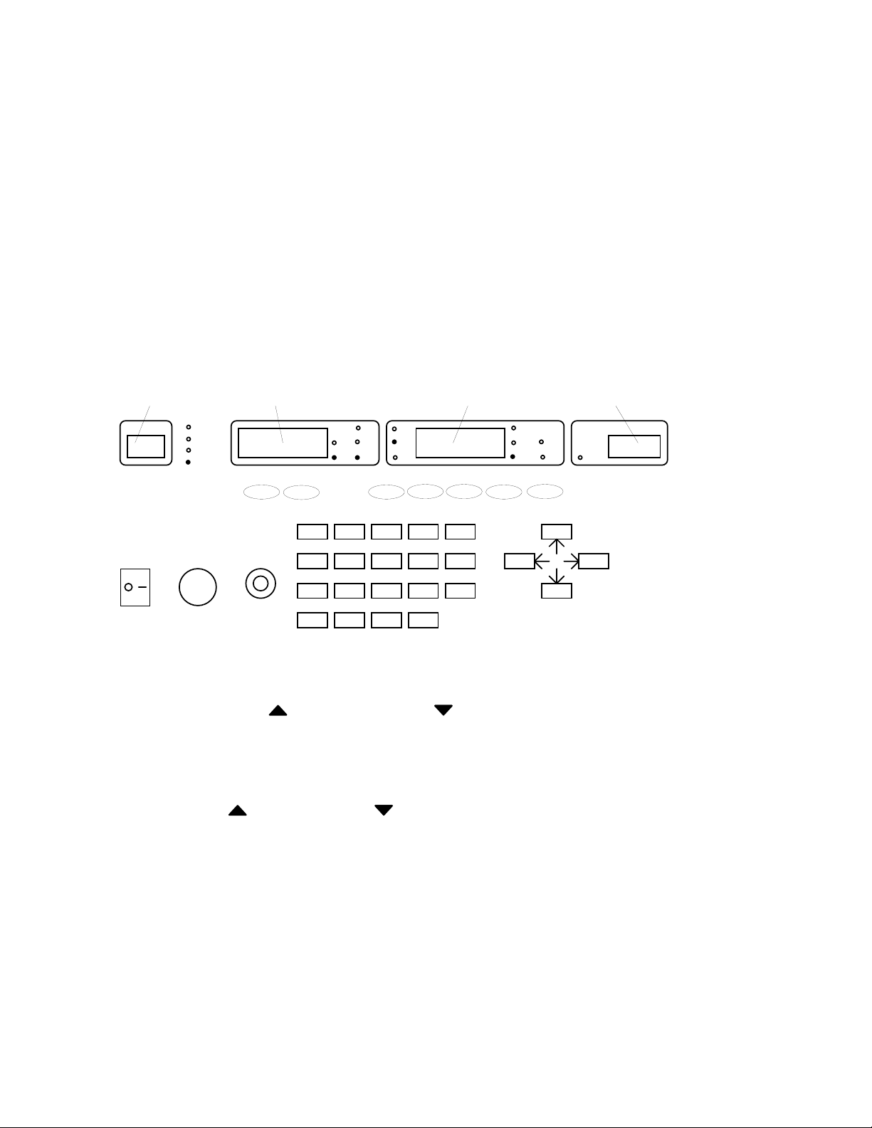
Figure 1-2 shows the controls and indicators on the front panel of the Guardian 5000. Table
1-1 identifies them with descriptions and functions.
12345 678 9 10 11 12 13 14 15 16
Introduction 1-2
Figure 1-2
Front Panel Controls & Indicators
17181920212223242526
Page 11

Table 1-1
Front Panel Controls and Indicators
Fig 1-2
Ref. # Item Function
1 Step Display indicates step number selected in the auto test sequence
(1 to 15). Indicates memory group number (1 to 50) when RCL
(recall) or STO (store) is selected.
2 Mode Light indicates that tester is in Ground Continuity, AC Hipot,
RΩ/W-ACV DC Hipot or Insulation Resistance mode status.
W-DCV/IR
3 RMT Light indicates when instrument is in remote mode.
Indicator
4 Voltage or Display shows voltage/voltage setting value when test is not in
Current process and shows output voltage/current when test is in process.
Display 0.1 - 5KV for AC Hipot, 0.5 - 6KV for DC Hipot,
100 - 1000V for IR, and 1.0 - 30.0A for GC,
5 LOCK Light indicates when instrument front panel keys are locked
Indicator
6 Display Units Indicates the units for the current/voltage display (AC or DC, A,
KV for hipot, V for IR or A for GC)
7 OFFSET Light indicates when instrument offset function is enabled.
Indicator
8 Limit Indicates the function of the limit shown on the Limit Display
Indicator (HI, LO, or ARC)
9 Limit/Measure Display shows limit setting when test is not in process and
shows measured value when test is in process.
10 Result Lights indicate test results based on set limits.
Indicators HI NG - Measured value exceeded high limit
LO NG - Measured value less than low limit
ARC NG - Measured value exceeded arc limit
PASS - Measured value is good based on all set limits
Introduction 1-3
Page 12

Table 1-1
Front Panel Controls and Indicators (continued)
Fig 1-2
Ref. # Item Function
11 Limit/Measure Indicates the units for the entered limits or the measured display
Display Units (mA for hipot, MΩ for IR or mΩ for GC)
12 Timer Indicates when test time shown is RAMP time
Indicator
13 CAL For use by qualified service personnel during instrument
ENABLE calibration.
14 Timer Display shows set time or time countdown when test is in
Display process. A test time of 0 (zero) places the instrument in a
continuous measure mode.
15 TEST ON When indicator light is blinking high voltage is present on the
Indicator output terminals.
16 HIGH High voltage output terminal (Hipot or Insulation Resistance
VOLTAGE tests)
17 LOW SENSE Low potential terminal (SENSE) for Ground Continuity test.
18 LOW Ground reference terminal for all tests
DRIVER
19 HIGH SENSE High potential terminal (SENSE) for Ground Continuity test.
20 HIGH High current terminals (DRIVER) for Ground Continuity test.
DRIVER
21 BUZZER Audible output for pass/fail results.
Introduction 1-4
Page 13

Table 1-1
Front Panel Controls and Indicators (continued)
Fig 1-2
Ref. # Item Function
22 CURSOR Under STOP status:
keys UP or DOWN to examine 1 - 15 steps
Under Hipot test On:
UP or DOWN to increase or decrease test voltage in
continuous mode
Under PROG status:
LEFT or RIGHT to select parameter for programming
UP
23 Data Entry [0] [.] .....[9] Numerical keys to input test parameters
Keys [OFF] For turning off test parameters (limits, arc, etc.)
[PROG] To enter and exit parameter setting status
[DELE] To delete a test step, those below move up
[CLEAR] To cancel parameter number and input again
[ENTER] Press to confirm enter parameter
[RCL] Recalls stored parameters (1 - 50) from memory
[STO] Stores parameter (1 - 50) into memory
[OFFSET] Initiates zeroing offset function
24 START Pressing this button starts a test and applies high voltage/current
button to the test terminals.
25 STOP Pressing this button stops a test in process and must be pressed
button as a reset function before a test can be started (after a failed test
or after test conditions have been reprogrammed).
26 OFF/ON Applies AC power to the tester, 0 is off, 1 is on.
or DOWN to change status status
Introduction 1-5
Page 14

1.4 Rear Panel Description
12 3 456 7
Figure 1-3
Rear Panel View
Table 1-2
Rear Panel Connectors and Controls
Fig 1-3
Ref. # Item Function
1 IEEE Input/output connections according to IEEE
STD-488.2. 24 pin socket for standard
IEEE-488 cable. Refer to paragraph 3.2
2 SCAN Input/output scanner interface for QuadTech 5000-01 or 5000-02
Multiport Scanner Matrix. Refer to Paragraph 3.3.
3 Voltage Switches for selecting range of AC power source
Selector - Set to 100V position for 90 - 100VAC operation
- Set to 120V position for 110 - 130VAC operation
- Set to 220V position for 200 - 240VAC operation
- Set to 240V position for 220 - 250VAC operation
!
4
AC Inlet Fuse drawer and 3-wire connection for AC power source. Module
Contains 7A, 250V, 5x20mm fuse for 90-130V operation or
3.5A, 250V, 5x20mm fuse for 200-250V operation
5 SIGNAL Contact closures for test in process, test results good, and test
OUTPUT results no good. Maximum contact rating is 115V at 0.3A.
6 Ground Chassis ground connection
7 Fan Temperature control fan
- on for > 50oC
- off for < 45oC
Introduction 1-6
Page 15

1.5 Accessories Included
Table 1-3
Item Quantity
Instruction Manual 1
Calibration Certificate 1
Power Cord 1
Power Line Fuse, 7A 2
S02, Test Lead Set, Hipot (1 red, 1 black, with alligator clips) 1
G15, Test Lead Set, GC (1 red, 1 black, with spring clips) 1
G14, Test Lead Set, Hipot (115V Receptacle) 1
1.6 Accessories/Options Available
Table 1-4
Item Part Number
Multiport Scanner Matrix (8 channel high V) 5000-01
Multiport Scanner Matrix (8 channel high V, 4 GC) 5000-02
Multiport Scanner Matrix, rack (8 channel high V) 5000-03
Multiport Scanner Matrix, rack (8 channel high V, 4 GC) 5000-04
High Voltage Lead Set, high & low, 1m (std w/unit) S02
High Voltage Lead Set, high & low, 2m S04
Foot Switch S05
High Voltage Probe S06
Gun Probe S08
High Voltage Lead, 1 meter, unterminated S09
High Voltage Lead, 2 meters, unterminated S10
Gun Probe with remote start S11
Load Box, resistive S12
Load Box custom resistors S14
Corded Product Adaptor G13
Power Entry Adaptor Cable, GC (std w/unit) G14
Ground Continuity Lead Set (std w/unit) G15
International Power Strip G16
Rear Panel Connection (factory installed) G22
Rack Mount Flanges (factory installed) G23
Corded Product Adaptor (240V) G25
RS232 Interface G26
Introduction 1-7
Page 16

1.7 Power Requirements
!
The Guardian 5000 can be operated from a power source of 90 to 130 VAC or 200 to
250 VAC. Power connection is via the rear panel through a standard receptacle. Before
connecting the 3-wire power cord between the unit and AC power source make sure the
voltage selection switches on the rear panel (as indicated) and fuses are in accordance with
the power source being used. 7A, 250V, 5x20mm, for 90-130V source and 3.5A, 250V,
5x20mm, for 200-250V source. Always use an outlet which has a properly connected
protection ground.
To change the fuse proceed as follows:
WARNING
MAKE SURE THE UNIT HAS BEEN DISCONNECTED FROM ITS AC POWER
SOURCE FOR AT LEAST FIVE MINUTES BEFORE PROCEEDING.
Remove the fuse drawer, by inserting a flat head screwdriver behind the small tab located just
below the 3 prong receptacle, and force outward.
Once the fuse drawer has been removed from the instrument snap the fuse from the holder
and replace. Make sure the new fuse is of the proper rating. Note that the fuse drawer can
also be used to store a spare fuse.
Install the fuse drawer back in the inlet module (fuse down) by pushing in until it locks
securely in place.
Introduction 1-8
Page 17

Section 2 Operation
2.1 Startup
Check to make sure the Voltage Selector Switch on the rear panel agrees with the power
source available (Depending on the power source the switch positions should be in the up or
down positions as shown).
WARNING
NEVER TOUCH THE TEST LEADS IN ANY MANNER (this includes insulation on all
wires and clips) WHEN THE HIGH VOLTAGE IS APPLIED AND RED DANGER
LIGHT ON.
USE ALL PRECAUTIONS NECESSARY TO AVOID TOUCHING THE DEVICE
UNDER TEST WHEN THE RED DANGER LIGHT IS ON OR BLINKING.
Connect the instrument power cord to the source of proper voltage. The instrument is to be
used only with three wire grounded outlets.
Power is applied to the Guardian 5000 by pressing the front panel POWER switch to ON (1
position).
WARNING
DO NOT TURN INSTRUMENT POWER ON OR OFF WITH TEST DEVICES CONNECTED.
2.2 Instrument Zeroing/Offset
The Guardian 5000 provides automatic zeroing/offset for lead or fixture effects. During the
zeroing/offset process a correction is made (subtracted out) as the result of lead leakage
current and stored in instrument memory to be applied to ongoing measurements. For
maximum measurement accuracy it is recommended that the unit be zeroed after power-up
and any time the test leads or fixture is changed (the offset is not saved under setup storage, 1
- 50 setups, but is saved on a power down and power back up. The instrument should
warm-up for at least 15 minutes before zeroing.
Operation 2-1
Page 18

Proceed as follows for automatic zeroing/offset:
• Plug the appropriate cable (or other fixture) into the front panel OUTPUT connectors,
with no device connected. Refer to paragraph 2.3 for cable configurations based on test
to be made. Test leads used for an AC Hipot, DC Hipot or Insulation Resistance
measurement should be open and those leads used for the ground continuity measurement
be shorted together before performing the zeroing offset.
• With the instrument in the power-up state (or in any other desired setup, refer to
paragraph 2.4 for recalling setups) press the OFFSET key.
STEP
1
>R
W-ACV
W-DCV
I-R
A
HI
KV
OFSt
RMT LOCK OFFSET HI-NG LO-NG ARC-NG PASS
AC
DC
LO
GEt
ARC
V
>m
uA
M >
TIMER
mA
TEST
>G
RAMP
SEC
5.0
Offset Key
OFF ON
STOP START
7 8 9 PROG
45
1
0
6
23
.
CLEAROFFSET
OFF ENTER
RCL
STODELE
CURSOR
• Display should read OFSt and GEt. Push the START button to initiate the automatic
storage of the offset value for all tests within a sequence.
• The offset will remain on until turned off by pressing the OFFSET key twice. If the
instrument is powered down with the offset on it remains in effect when the unit is again
powered up.
The following formulas apply to the offset function:
For AC offset current < 80µA:
22
−
Display current = current read offset current
()( )
For DC offset or AC offset current ≥ 80µA:
Display current = (current read) - (offset current)
Operation 2-2
Page 19

2.3 Connection to Device Under Test
Before connecting the device for test Press the STOP key and make sure the red DANGER
light is not on.
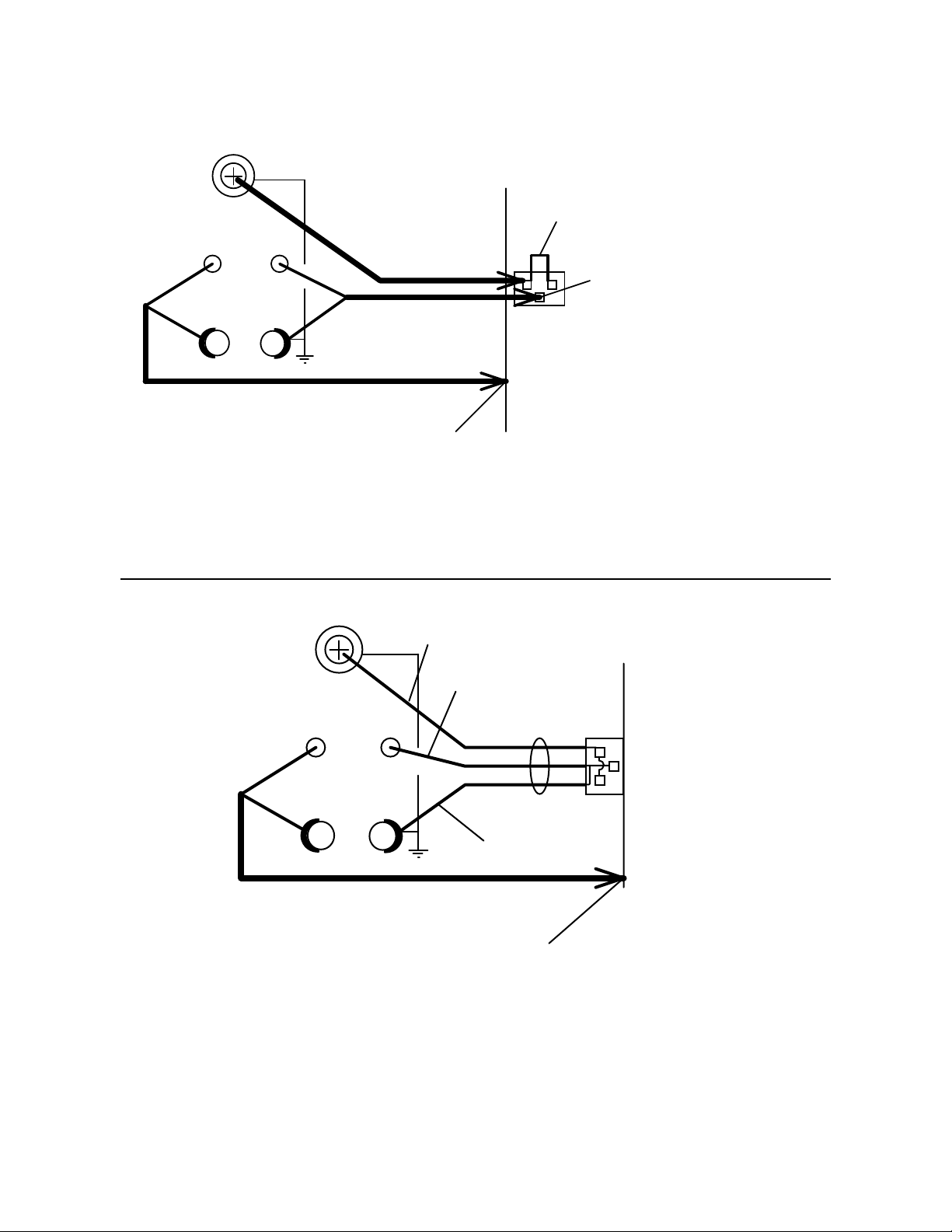
Depending on the test to be conducted (Hipot, IR or Ground Continuity) connect the test
cables to the front panel OUTPUT connectors. Refer to the following figures to determine the
correct configuration. When using the black cable, with the metal retaining bracket, make
sure it is locked behind the connector to prevent this cable from accidentally coming loose.
WARNING
NEVER TOUCH THE TEST LEADS OR THE DEVICE UNDER TEST WHEN THEY
ARE CONNECTED TO THE INSTRUMENT AND THE RED DANGER LIGHT IS
ON OR BLINKING.
HIGH-VOLTAGE
UNKNOWN
HIGH LOW
SENSE
DRIVER
Connection for Hipot/IR Test
(Using S02 Two Lead Test Set)
Alligator Clip Lead
(Red)
WV
With Retaining Bracket
Alligator Clip Lead
(Black)
Figure 2-1
Shorted
Together
Device Under
Test
(DUT)
Operation 2-3
Page 20

HIGH-VOLTAGE
UNKNOWN
HIGH LOW
SENSE
DRIVER
Large Alligator Clip Lead
Large Alligator Clip Lead
WV
(Red)
Connect to Case
of DUT
Connection for Ground Continuity Test
(Using G15 Two Lead Set, Large Clips)
HIGH-VOLTAGE
(Black)
Figure 2-2
Connect to Power Ground
of DUT
Device Under
Test
(DUT)
Red Lead
UNKNOWN
Black Lead With
Retaining Bracket
HIGH LOW
SENSE
WV
Device Under
Test
(DUT)
DRIVER
Black Lead
With Lug
Figure 2-3
Connection for Hipot Test
(Using G14 Power Entry Cable)
Operation 2-4
Page 21
HIGH-VOLTAGE
UNKNOWN
HIGH LOW
SENSE
DRIVER
Large Alligator Clip Lead
WV
(Red)
Alligator Clip Lead
(Red)
Large Alligator Clip Lead
(Black)
Connect to Case
of DUT
Shorted
Together
Connect to Power Ground
of DUT
Device Under
(DUT)
Test
Figure 2-4
Connection for Hipot and Ground Continuity Test
(Using S02 (HV cable) and G15 Clip Lead Sets)
HIGH-VOLTAGE
Red Lead
UNKNOWN
Black Lead With
Retaining Bracket
HIGH LOW
SENSE
WV
Device Under
Test
DRIVER
Black Lead
With Lug
Large Alligator Clip Lead
(Red)
Connect to Case
of DUT
Figure 2-5
Connection for Hipot and Ground Continuity Test
(Using G15 (one cable) & G14 Power Entry Cable)
(DUT)
Operation 2-5
Page 22

2.4 Measurement Procedure
Once the instrument has been powered up, the offset function implemented and the device
under test connected, testing can begin. The operator has the choice of performing a test at
power-up conditions (test conditions at which the instrument was last powered down), or
recalling one of 50 possible stored setups. Refer to paragraph 2.5 thru 2.8 for instructions to
change the test mode and/or test conditions.
To initiate a test proceed as follows:
• Press STOP (red button) to place the instrument in its standby ready-to-test state.
Test Sep # (1 -15) or
Setup # (1 - 50) entered from keypad in RECALL mode
STEP
1
OFF ON
>R
W-ACV
W-DCV
I-R
STOP START
2.50
RMT LOCK OFFSET HI-NG LO-NG ARC-NG PASS
A
HI
KV
AC
DC
7 8 9 PROG
45
23
1
.
0
LO
ARC
V
6
CLEAROFFSET
OFF ENTER
5.00
RCL
STODELE
>m
uA
M >
CURSOR
TIMER
mA
TEST
>G
RAMP
SEC
5.0
Press to Recall
Setup #
• Press START (green button) to start the test. When this button is pressed the high voltage
is turned on. This is indicated by the DANGER light being on to warn the operator that
high voltage or current is present at the test leads. The step display indicates the step # (1
- 15) within a sequence of tests, voltage/current display will indicate its value, the
measure display will show current or resistance value and the timer will show ramp and
test time countdown.
• Depending on the test conditions, the test voltage or current will cut off if a limit is
exceeded or cut off when the test time has expired. In the case of a FAIL situation the
STOP button must be pressed to stop the buzzer.
• The STOP button can be pressed at any time to stop the test.
Operation 2-6
Page 23

To recall one of the 50 setups proceed as follows:
• Press the RCL key.
• The STEP display shows the current setup # selected. From the front panel keypad type
in the setup number desired (1 - 50).
• Press ENTER to load the stored test conditions and then initiate a test as just described.
Operation 2-7
Page 24

2.5 Programming Tests Mode
Each test can consist of 1 to 15 steps in sequence, for example, a typical three step test might
be an AC hipot test followed by an IR test and followed by a Ground Continuity test. Each
step may be programmed for any available function (ACV, DCV, IR or R-Ω for ground
continuity) with programmed test conditions independent from the other step.
To change the test mode proceed as follows:
• With the instrument in standby status (Stop button previously pressed and no lights
blinking) press the UP
higher. Note the test mode indicator light to the right of the step display, this light
indicates if a particular step selected is AC/DC hipot, an insulation resistance test or
ground continuity test. Press the DOWN key to return to the lower steps. Remember,
up to 15 steps within a single test are possible.
Test Step
cursor one or more times to select or examine steps 2 and
TIMER
mA
TEST
>G
RAMP
SEC
5.0
STEP
1
OFF ON
>R
W-ACV
W-DCV
I-R
2.50
RMT LOCK OFFSET HI-NG LO-NG ARC-NG PASS
STOP START
A
HI
KV
AC
DC
7 8 9 PROG
45
23
1
.
0
LO
ARC
V
6
CLEAROFFSET
OFF ENTER
5.00
RCL
STODELE
>m
uA
M>
CURSOR
For a single step test, the test voltage (or current for a ground continuity test) for
step 2 must be set to 0.00. In a similar fashion, for a two step test the voltage or
current for step 3 must be set to 0.00.
Test Step
STEP
2
>R
W-ACV
W-DCV
I-R
Test Voltage (voltage set to 0 inhibits step 2)
A
HI
KV
0.00
AC
DC
LO
5.00
ARC
V
>m
uA
M >
TIMER
mA
TEST
>G
RAMP
SEC
5.0
Operation 2-8
Page 25

• To change a test mode select the step to be changed (1 to 15) as described above and press
PROG and then ENTER (the VAC/VDC /IR/RΩ light will be blinking).
• Arrow UP or DOWN to the newly desired test mode (VAC/VDC/IR/RΩ) and
press ENTER again.
• Once the desired test mode has been selected refer to paragraph 2.6 for changes to Hipot
test conditions and paragraph 2.7 for changes to IR test conditions and paragraph 2.8 for
changes to Ground Continuity test conditions.
Example of test mode change (step 1 an AC Hipot and step 2 an IR test):
• In standby mode (with no light blinking), arrow UP or arrow DOWN to select
Step 1. Press PROG and then ENTER. UP or arrow DOWN to select W-ACV
for this step and then ENTER.
Starting with test voltage enter the test conditions for step 1 as discussed in paragraph 2.6
for Hipot test conditions. Return to standby mode (with no light blinking) by pressing
PROG key
• In standby mode (with no light blinking), arrow UP or arrow DOWN to select
Step 2. Press PROG and then ENTER. UP or arrow DOWN to select I-R for this
step and then ENTER.
Starting with test voltage enter the test conditions for step 2 as discussed in paragraph 2.7
for IR test conditions. Return to standby mode (with no light blinking) by pressing
PROG key
Operation 2-9
Page 26

2.6 Programming Hipot Test
Test Voltage Leakage Current TimeTest Step
STEP
1
OFF ON
>R
W-ACV
W-DCV
I-R
STOP START
2.50
RMT LOCK OFFSET HI-NG LO-NG ARC-NG PASS
A
HI
KV
AC
DC
7 8 9 PROG
45
23
1
.
0
LO
ARC
V
6
CLEAROFFSET
OFF ENTER
5.00
RCL
STODELE
>m
uA
M>
CURSOR
TIMER
mA
TEST
>G
RAMP
SEC
5.0
With the instrument in standby status (Stop button previously pressed and no lights blinking)
press the arrow UP or arrow DOWN to select the test step # (1 - 15) to be
programmed. If the desired selection is an AC or DC hipot test proceed as described below, if
selection is an IR test refer to paragraph 2.7, if selection is ground continuity refer to
paragraph 2.8.
Press PROG key and ENTER to begin the parameter change. The test mode indicator will
blink, arrow UP or arrow DOWN to select W-ACV (AC Hipot) or W-DCV (DC
Hipot) and press ENTER.
Test Voltage
From the Data Entry Keys type the desired test voltage and then press ENTER. (0.10 to
5.00KV AC and 0.5 to 6.00KV DC are the allowable ranges)
Hi Limit
From the Data Entry Keys type the desired high current limit and then press ENTER. (0.300
to 40.00mA AC, or 20.00mA DC is the allowable range). Any measured value of leakage
current above this will result in a fail decision.
Lo Limit
From the Data Entry Keys type the desired low current limit and then press ENTER. (0.100
to 1/2 the Hi Limit is the allowable range). Any measured value of leakage current below this
will result in a fail decision. An entry of 0 disables the limit detection.
Operation 2-10
Page 27

Arc
From the Data Entry Keys type the desired arc current limit and then press ENTER. (0.500
to 40.00mA AC, or 20.00mA DC is the allowable range). Any measured value of arc current
above this will result in a fail decision. An entry of 0 disables the limit detection.
Test Time
From the Data Entry Keys type the desired test time and then press ENTER. (0.1 to 999s is
the allowable range). A test time of 0 sets the instrument to continuous test mode.
WARNING
EXTREME CAUTION MUST BE USED BY THE OPERATOR, IN CONTINUOUS
MODE, HIGH VOLTAGE IS APPLIED TO THE TEST TERMINALS UNTIL THE
STOP BUTTON IS DEPRESSED OR A LEAKAGE CURRENT BREAKDOWN
OCCURS.
Ramp Time
From the Data Entry Keys type the desired ramp time and then press ENTER. (0.1 to 99.9s
is the allowable range). A test time of 0 for a display of [ - - - - ] sets the ramp time to zero.
After the final test condition entry (ramp time) the instrument returns to the blinking test step
#. Press PROG key to return to standby status in preparation for testing.
OR
If test conditions are to be changed in another step, arrow UP or arrow DOWN to
select the other step:
• if a hipot test, set the test conditions as described in this paragraph.
• if a insulation resistance test refer to paragraph 2.7 for setting test conditions.
• if a ground continuity test refer to paragraph 2.8 for setting test conditions.
Operation 2-11
Page 28
To store the present set of test conditions proceed as follows:
• If the instrument is in programming mode (any lights blinking) press the PROG key.
• Press the STO key.
• From the Data Entry Keys type the setup number desired (1 - 50).
• Press ENTER to store the present test conditions.
2.7 Programming Insulation Resistance (IR) Test
Test Voltage TimeTest Step
Resistance
STEP
OFF ON
>R
W-ACV
W-DCV
I-R
STOP START
7502
RMT LOCK OFFSET HI-NG LO-NG ARC-NG PASS
A
HI
KV
AC
DC
7 8 9 PROG
45
23
1
.
0
LO
ARC
V
6
CLEAROFFSET
OFF ENTER
2.00
RCL
STODELE
>m
uA
M>
CURSOR
TIMER
mA
TEST
>G
RAMP
SEC
5.0
With the instrument in standby status (Stop button previously pressed and no lights blinking)
press the arrow UP
or arrow DOWN to select the test step # (1 - 15) to be
programmed. If the desired selection is an IR test proceed as described below, if selection is a
Hipot test refer to paragraph 2.6, if selection is ground continuity refer to paragraph 2.8.
Press PROG key and ENTER to begin the parameter change. The test mode indicator will
blink, arrow UP or arrow DOWN to select I-R and press ENTER.
Operation 2-12
Page 29

Test Voltage
From the Data Entry Keys type the desired test voltage and then press ENTER. (100 to
1000V DC are the allowable ranges, in 1 steps).
Lo Limit
From the Data Entry Keys type the desired low resistance limit and then press ENTER.
(10MΩ to 9999MΩ is the allowable range). Any measured resistance value below this will
result in a fail decision.
Hi Limit
From the Data Entry Keys type the desired high resistance limit and then press ENTER.
(10MΩ to 9999MΩ is the allowable range and must be above the low limit). Any measured
resistance value above this will result in a fail decision.
Test Time
From the Data Entry Keys type the desired test time and then press ENTER. (0.1 to 999s is
the allowable range). A test time of 0 with display of [ - - - - ] sets the instrument to
continuous test mode.
WARNING
EXTREME CAUTION MUST BE USED BY THE OPERATOR, IN CONTINUOUS
MODE, HIGH VOLTAGE IS APPLIED TO THE TEST TERMINALS UNTIL THE
STOP BUTTON IS DEPRESSED OR A FAILURE RESULTING FROM THE SET
LIMIT OCCURS.
After the final test condition entry (TEST time) the instrument returns to the blinking test step
#. Press PROG key to return to standby status in preparation for testing.
OR
If test conditions are to be changed in another step, arrow UP or arrow DOWN to
select the other step:
• if an insulation resistance test, set the test conditions as described in this paragraph.
• if a hipot test refer to paragraph 2.6 for setting test conditions.
• if a ground continuity test refer to paragraph 2.8 for setting test conditions.
To store the present set of test conditions proceed as follows:
• If the instrument is in programming mode (any lights blinking) press the PROG key.
• Press the STO key.
• From the Data Entry Keys type the setup number desired (1 - 50).
• Press ENTER to store the present test conditions.
Operation 2-13
Page 30

2.8 Programming Ground Continuity Test
Test Current
Resistance
TimeTest Step
STEP
3
OFF ON
>R
W-ACV
W-DCV
I-R
STOP START
25.0
RMT LOCK OFFSET HI-NG LO-NG ARC-NG PASS
A
HI
KV
AC
DC
7 8 9 PROG
45
23
1
.
0
LO
ARC
V
6
CLEAROFFSET
OFF ENTER
300
RCL
STODELE
>m
uA
M>
CURSOR
TIMER
mA
TEST
>G
RAMP
SEC
5.0
With the instrument in standby status (Stop button previously pressed and no lights blinking)
press the arrow UP or arrow DOWN to select the test step # (1 - 15) to be
programmed. If the desired selection is a ground continuity test proceed as described below,
if selection is a Hipot test refer to paragraph 2.6, if selection is insulation resistance refer to
paragraph 2.7.
Press PROG key and ENTER to begin the parameter change. The test mode indicator will
blink, arrow UP or arrow DOWN to select R-Ω and press ENTER.
Test Current
From the Data Entry Keys type the desired test current and then press ENTER. (1.0 to 30.0A
AC are the allowable ranges, in 0.1A steps).
Hi Limit
From the Data Entry Keys type the desired high resistance limit and then press ENTER.
(0.1mΩ to 500mΩ is the allowable range). Any measured resistance value above this will
result in a fail decision.
Test Time
From the Data Entry Keys type the desired test time and then press ENTER. (0.1 to 999s is
the allowable range). A test time of 0 sets the instrument to continuous test mode.
Operation 2-14
Page 31

WARNING
EXTREME CAUTION MUST BE USED BY THE OPERATOR, IN CONTINUOUS
MODE, HIGH CURRENT IS APPLIED TO THE TEST TERMINALS UNTIL THE
STOP BUTTON IS DEPRESSED OR A FAILURE RESULTING FROM THE SET
LIMIT OCCURS.
After the final test condition entry (TEST time) the instrument returns to the blinking test step
#. Press PROG key to return to standby status in preparation for testing.
OR
If test conditions are to be changed in another step, arrow UP or arrow DOWN to
select the other step:
• if a ground continuity test, set the test conditions as described in this paragraph.
• if a hipot test refer to paragraph 2.6 for setting test conditions.
• if an insulation resistance test refer to paragraph 2.7 for setting test conditions.
To store the present set of test conditions proceed as follows:
• If the instrument is in programming mode (any lights blinking) press the PROG key.
• Press the STO key.
• From the Data Entry Keys type the setup number desired (1 - 50).
• Press ENTER to store the present test conditions.
Operation 2-15
Page 32

2.9 Initial Parameter Settings
The Guardian 5000 has a number of parameter setting that seldom require change, the
instrument will power-up with default setting. Each of these parameters are listed in the table
below and can be changed using the following procedure.
Parameter Name
(on Limit display)
St - 1 1 - 30 3 IEEE-488 address
St - 2 50 - 600 60 Hipot VAC freq.
St - 3 50/60 60 GC VAC freq.
St - 4 0.3 - 99.9sec 1 IR test delay
St - 5 0.2- 99.9sec 0.5 PASS hold time
St - 6 0.1- 99.9sec 1 STEP delay time
St - 7 6.0 - 15 volts 15.0 volts GC voltage
St - 8 ON / OFF ON AGC control
St - 9 OFF / 1 / 2 / 3 3 (max) Buzzer
St - A ON / OFF ON PASS hold
ST-b 1 - 8 1 Scanner #
St - C ON / OFF OFF Continue on FAIL
To select initial parameter setting mode:
With the instrument in standby status (Stop button previously pressed and no lights blinking)
press ENTER and then [5] [0] [0] [0]. The limit display will indicate parameter St - 1, and
others (Table 2-1) can be selected by arrow UP or arrow DOWN . Select the St #
desired for change. Once a change is made and the ENTER key pressed the instrument
moves to the next initial setting, if this is not the one desired, arrow UP
to select another. To exit the initial parameter setting mode press PROG.
St - 1 (IEEE-488 Address)
The current address is shown on the Timer display. From the Data Entry Keys type the
address number desired [1 - 30] and ENTER.
St - 2 (AC Hipot test frequency)
The current frequency is shown on the Timer display. From the Data Entry Keys type the
frequency desired [50 - 600] and ENTER.
Selection Range
(on Timer display)
Initial Parameter Setting
Default Value Function
Table 2-1
or arrow DOWN
Operation 2-16
Page 33

St - 3 (Ground Continuity test frequency)
The current frequency is shown on the Timer display. From the Data Entry Keys type the
frequency desired [50 or 60] and ENTER.
St - 4 (IR test delay time)
The current delay time is shown on the Timer display. From the Data Entry Keys type the
time desired [.3 - 999] and ENTER.
St - 5 (Pass indicator hold time)
The current Pass indicator hold time (time in which the Pass indicator remains on after test is
complete) is shown on the Timer display. From the Data Entry Keys type the time desired [.2
- 99.9] and ENTER.
St -6 (step delay)
The current delay time (delay time between steps) is shown on the Timer display. From the
Data Entry Keys type the time desired [.1 - 99.9] and ENTER.
St - 7 (Ground Continuity voltage)
The current ground continuity test voltage is shown on the Timer display. From the Data
Entry Keys type the test voltage desired [6.0 - 15.0] and ENTER.
St - 8 (Hipot automatic gain control)
The current AGC setting (on or off) is shown on the Timer display. From the Data Entry Keys
press the OFF key to toggle the on/off.
St - 9 (Buzzer)
The current Buzzer setting (off or audible levels of 1, 2, or 3) is shown on the Timer display.
From the Data Entry Keys press the OFF or 1, 2, or 3 key and ENTER to turn off or on. 1 is
low volume, 2 is mid-range volume and 3 is high volume.
St - A (Pass indicator hold)
The current Pass indicator hold, on or off (with selection of on Pass indicator remains on until
the next test is initiated) is shown on the Timer display. From the Data Entry Keys press the
OFF key to toggle the on/off.
St - b (# of scanner)
The current # of scanner selected (1 - 8) is shown on the Timer display. From the Data Entry
Keys type the number of scanners to be connected [1 - 8] and ENTER.
St - C (Continue on fail)
The current setting for continue on fail (on or off) is shown on the Timer display. From the
Data Entry Keys press the OFF key to toggle the on/off.
Operation 2-17
Page 34

2.10 Front Panel Lockout
With front panel lock in effect the ability to change test conditions is prohibited. Only the
START and STOP buttons and the setup recall function (RCL) are functional.
To activate the front panel lockout:
• With the instrument in standby status (Stop button previously pressed and no lights
blinking) enter [5] [0] [0] [0] and [OFF] from the data entry keys. The LOCK indicator
light will illuminate indicating the instrument is in the lockout state.
To deactivate the front panel lockout:
• With the instrument in standby status (Stop button previously pressed and no lights
blinking) enter [5] [0] [0] [0] and [OFF] from the data entry keys. The LOCK indicator
light will go out indicating the instrument is no longer in the lockout state.
2.11 Software Version Display
The version of software, installed in the instrument, can be displayed on the front panel.
To display software version:
• Press the front panel POWER switch to ON and immediately press the ENTER key. The
year will be shown in the left display and the month and day in the right display as
illustrated below. This software version display is only held for a couple of seconds.
>m
mA
uA
>G
M >
1997
HI
V
KV
DC
AC
LO
02
ARC
A
15
2.12 Clear Setup Memory
All stored test conditions in instrument memory (50 setups) can be cleared with a few key
strokes.
To clear setup memory:
• With the instrument in standby status (Stop button previously pressed and no lights
blinking) press CLEAR and then [5] [0] [0] [0] and CLEAR again.
Operation 2-18
Page 35

Section 3 Input/Output Interfaces
3.1 Remote
A remote control connector is located on the rear panel of the instrument with input
connections for starting and stopping the unit externally and output connections indicating
instrument status and a safety interlock connection.
Inputs require a contact closure and outputs provide a contact closure, as shown in the figure
below.
Before connecting the instrument to its power source the interlock function on the rear panel
remote connector must be properly utilized. This is an important safety feature for the
protection of the operator. Turn on of the instrument's high voltage is inhibited with no
interlock connection and is functional with the interlock jumper in place (as shipped from the
factory).
START
STOP
COM
INPUTS
INTERLOCK
UNDER TEST
PASS
FAIL
Rear Panel
Remote Connector
OUTPUTS
Figure 3-1
Remote Control Connector
Maintenance & Calibration 3-1
Page 36

close
START
open
close
UNDER TEST
open
PASS CONDITION FAIL CONDITION
close
PASS
open
close
FAIL
open
close
STOP
open
close
INTERLOCK
open
215ms 215ms
215ms
215ms
Maintenance & Calibration 3-2
Page 37

3.2 IEEE-488 Interface
3.2.1 Description
The Guardian 5000 includes an IEEE-4888 interface with connection through a connector (24
pin) on the rear panel. This interface can be used to connect to a system containing a number
of instruments and a controller in which each meets IEEE Standard 488.2 (Standard Digital
Interface for Programmable Instrumentation).
The following functions have been implemented:
Code Function
SH1 Source Handshake
AH1 Acceptor Handshake
T4 Basic Talker Function
L4 Basic Listener Function
SR0 No Service Request Function
RL1 All Remote/Local Function
PP0 No Parallel Poll Function
DC1 All Device Clear Function
DT0 Device Trigger Function
C0 No Controller Functions
The address is defined in the INITIAL setting for St-1, refer to paragraph 2.9
The instrument is in a remote control status when the RMT indicator is on.
To switch to Local from Remote press the [PROG] key, disabled by LLO message.
The only controls functional under Remote operation is [PROG], which switches to Local and
STOP which resets the unit.
Intf Message Function Description
GET Ground Execute Trigger Response depends on the *DDT, setting to
START or STOP
GTL Go To Local Switch unit to local
SDC Selected Device Clear Reset the unit
LLO Local Lockout Disables [PROG] switch to local
IFC Interface Clear Reset bus interface
Maintenance & Calibration 3-3
Page 38

3.2.2 Interface Commands
The interface function is controlled by ASCII commands which include:
{[command + parameter] ; [command + parameter] + ending code}
The length of the string is 128 characters. It is not necessary to input any sign or space
between the command and parameter. Any two commands can be connected by "," and
[Ending Code]. Ending Code can be any type of the following.
Ending Code
LF
CR + LF
EOI
LF + EOI
CR + LF + EOI
Maintenance & Calibration 3-4
Page 39

3.2.2.1 Listener Functions
Item Command Parameter Function
1 STOP X stop test
2 TEST X start test
3 SHOW (?) {c} set testing value
4 STEP (?) {n} set Step
5 MODE (?) {n | c} set test mode
6 SOUR (?) {f} set output voltage or current
7 VOLT (?) {f} set output voltage
8 CURR (?) {f} set output current
9 HILI (?) {f | *} set High Limit
10 LOLI (?) {f | *} set Low Limit
11 SARC (?) {f | *} set ARC
12 HICH (?) {n | *} set High Channel
13 LOCH (?) {n | *} set Low Channel
14 TIME (?) {f | *} set the test time
15 RAMP (?) {f | *} set the voltage rise time
16 *SAV {n} save the setting value
17 *RCL {n} read the setting value
18 CLER X clear the memory
19 *IDN (?) X check the unit number
20 *DDT (?) {n | c} set the response to Trigger
21 *TRG X execute Trigger command
22 *RST X reset the unit
where x: no parameter required
n: indicates integer
f: indicates floating
c: indicates memory mark
*: indicates the "*" character of ASCII
Maintenance & Calibration 3-5
Page 40

1. STOP
Stop testing, same as STOP on front panel.
2. TEST
Start testing, same as START on front panel.
3. SHOW (?) {c}
Check the testing value, [STATUS] [STEP] [MODE] [SOURCE] [MEASURE]
[TIMER] [CHAN] [SAVE]
The command can connect each parameter with "|". Each parameter can be
abbreviated. Ex: STA=STATUS, STE=STEP
A delay ≥ 150 msec should be used between commands during measurements.
4. STEP (?) {n}
Step number (1 - 15). Set step number first before setting test conditions for that
step.
5. MODE (?) {n | c}
Set test mode by number or memory sign.
Ground Continuity 0, G or GR
AC Hipot 1, A or WA
DC Hipot 2, D or WD
Insulation Resistance 3, I or IR
If testing mode is changed the test conditions will be cleared to the initial value.
6. SOUR (?) {f}
Set the output voltage of current according to mode selected.
Ground Continuity f = 1 - 30 Amp
AC Hipot f = 0.1 - 5.0 KV
DC Hipot f = 0.5 - 6.0 KV
Insulation Resistance f = 100 - 1000 V
The output voltage for current can be set by SOUR or VOLT or CURR directly.
VOLT or CURR is the recommended method to avoid improper setting
(5 Amp could be interchanged for 5 KV, depending on the MODE selected).
For Ground Continuity the high resistance limit is determined by the current setting.
The maximum high resistance limit is 510mΩ or R = 6.3 V/I (i.e. if the current is 30
Amps the high limit could not exceed 210mΩ.
7. VOLT (?) {f}
Set the output voltage (similar to SOUR). Indicates error 1 if mode is selected for
Ground Continuity.
8. CURR (?) {f}
Set the output current (similar to SOUR). Indicates error 1 if mode is selected for
anything other than Ground Continuity.
Maintenance & Calibration 3-6
Page 41

9. HILI (?) {f | *}
Set the high limit value according to mode selected. * disables the high limit.
Ground Continuity f = 0.1 - 500.0 mΩ
AC Hipot f = 0.01 - 40.00 mA
DC Hipot f = 0.01 - 20.00 mA
Insulation Resistance f = 1 - 9999 MΩ
In Hipot mode if the High Limit/2 is smaller than the Low Limit, the low limit is
disabled.
In IR mode the value can not be smaller than the Low Limit, otherwise error 2 is
indicated.
In Ground Continuity mode the maximum high resistance limit is 510mΩ or
R = 6.3 V/I (i.e. 210mΩ for 30 Amps).
10. LOLI (?) {f | *}
Set the low limit value according to mode selected. * disables the low limit.
Ground Continuity f = 0.1 - 500.0 mΩ
AC Hipot f = 0.01 - 40.00 mA
DC Hipot f = 0.01 - 20.00 mA
Insulation Resistance f = 1 - 9999 MΩ
In Hipot mode the limit is disabled if greater than High Limit/2.
In IR mode the limit is disabled if greater than the High Limit.
In Ground Continuity mode the limit can not be set.
11. SARC (?) {f | *}
Set the arc limit value (Hipot mode only). * disables the limit.
AC Hipot f = 0.01 - 40.00 mA
DC Hipot f = 0.01 - 20.00 mA
12. HICH (?) {n | *}
Set the High Channel from 1 - 8. * disables the limit. More than one channel is
possible (Ex: HICH 1 3 5).
13. LOCH (?) {n | *}
Set the Low Channel from 1 - 8. * disables the limit. More than one channel is
possible (Ex: LOCH 1 3 5). Can not be set in Ground Continuity mode.
14. TIME (?) {f | *}
Set the Test Time from 0.1 - 99.9 sec. * disables the time.
15. RAMP (?) {f | *}
Set the voltage rise time from 0 - 99.9 sec for Hipot mode. * disables the time.
Maintenance & Calibration 3-7
Page 42

16. *SAV {n}
Save the test conditions for later recall (up to 15 steps each) in memory location: 1-
50.
17. *RCL (?) {n}
Recall the test conditions that have been saved (up to 15 steps each) in memory
location 1 - 50.
18. CLER
Resets the instrument from interface control. The address function is till in
effect.
19. *IDN
Checks the instrument for identification.
20. *DDT (?) {n | c}
Determines the response from the interface when the instrument receives TRG or GET
command.
0 or S Stop testing
1 or T Start testing
2 or NS Stops testing after receiving TRG or GET command and
DDT will change to NT.
3 or NT Starts testing after receiving TRG or GET command and
DDT will change to NS.
21. *TRG
Triggers the instrument and functions the same as interface message GET. This is
dependent on the setting of DDT, see above.
22. *RST
Resets the instrument and functions the same as interface message SDC
Maintenance & Calibration 3-8
Page 43

3.2.2.2 Talker Functions
The message of {string + ending code} will be sent when the instrument is assigned as
TALKER. The ending code consists of CR+LF+EOI. The string is dependent on the present
status.
There are several commands with the "?". These commands send the testing value by ASCII
string.
Example:
1. Command : mode WD: mode?
: MODE 2 : With Standing DC voltage test mode.
2. Command : high 1|3|5; high?
:HICH 1|3|5 ; High Channel 1,3,5 is ON
All commands will feed back an error message except *RST, *TRG , show and "?'. If the
error code is not 0 the result will be displayed. Error messages are as follows:
Error Messages
Error 0: Save OK!
Error 1: The command is not valid
Error 2: The parameters are not valid
Error 3: Can not start test
Error 4: Scanner is not connected
Error 5: Channel can not set 0
Error 6: Channel invalid
The TALKER function is completed by SHOW(?) command. The instrument will send back
the testing value for the parameter selected. It may check more than one test value by
connecting the parameters with "|".
Status Messages
Status 0: Presently in STOP status
Status 1: Presently in TEST status
Status 2: Test complete, condition is PASS
Status 3: Test stop, condition is FAIL
Status 4: Test stop, Hipot arc limit FAIL
Status 5: Test stop, Hipot high limit FAIL
Status 6: Test stop, Hipot low limit FAIL
Status 7: Test stop, IR high limit FAIL
Status 8: Test stop, IR low limit FAIL
Status 9: Test stop, GC high limit FAIL
Maintenance & Calibration 3-9
Page 44

1. STATUS
To check the present status, with status code. Output from is:
STATUS_X--8 bytes
note: "_" denotes a space
2. STEP
To check the present step. Output form is STEP_XX--7 bytes
3. MODEL
To check the testing mode. Output form is MODE_X--6 bytes
4. SOURCE
To check the output voltage or current. Output form is:
1) GC Mode AC_XXX>XX_A
2) AC Mode AC_XX>XX_KV
3) DC Mode DC_XX>XX_KV
4) IR Mode DC.XXXX__V
total: 11 bytes
5. MEASURE
To check the tested resistance or current. Output form is:
MEASURE_XXXXX_UU
where XXXXX is the measured value and UU the units
total: 16 bytes
6. TIMER
To check the test time remaining. Output form is:
1) TIME_XX.X
2) RAMP_XX.X
total: 9 bytes
7. CHAN
To check the channel status. Output form is:
HICH_X|X| .....|X, LOCH_X|X|.....|X
total: 13 to 41 bytes
8. SAVE
To save the data of each test. The unit can read the data without the SHOW
parameter.
Example: Write : SHOW Step|save
Read : STEP 1
Read : STEP 1
Write : SHOW mode
Read : MODE 1
Read : STEP 1 shows step by SHOW step|save
SAVE parameter can not be used alone
Example: SHOW SAVE will display Error 2
Maintenance & Calibration 3-10
Page 45

If the instrument is required to display saved item, just use SHOW? command
If the instrument is required to display more than one testing value, no matter
what the order of parameters, the output will display the following.
[STATUS], [STEP],[MODE],[SOURCE],[MESSAGE],[TIMER],[CHAN]
any two parameters separated by a ","
Example: Write: SHOW STEP|STATUS|MODE
Read: STATUS 2, STEP 1, MODE 1
The string length sent by SHOW may not be more than 106 bytes (including
ending code)
3.2.3 Sample QuickBASIC Program
REM $INCLUDE: 'qbdecl.bas'
'declarations
ADAP$ = "GPIB0": G5000$ = "DEV3": V% = 1
W% = 0: C$ = SPACE$(50): d$ = SPACE$(50): C1$ = SPACE$(50): D1$ = SPACE$(50)
STAT$ = SPACE$(50)
'find IEEE card and G5000
CALL IBFIND(ADAP$, GPIB0%)
CALL IBFIND(G5000$, G5000%)
CLS 'clear screen
'read identification from g5000
CALL IBWRT(G5000%, "*IDN")
CALL IBRD(G5000%, D1$)
PRINT D1$
'open a file to store data and status to
20
PRINT "FILE NAME TO STORE RESULT (less than 8 characters)"
INPUT NAME$
IF LEN(NAME$) = 0 THEN NAME$ = "DATA"
IF LEN(NAME$) > 8 THEN GOTO 20
NAME$ = NAME$ + ".TXT"
OPEN NAME$ FOR APPEND AS #1
Maintenance & Calibration 3-11
Page 46

'ask user for mode, voltage, current, ramp and test time
50
PRINT "MODE 1 = AC, 2 = DC"
INPUT MODE$
IF MODE$ = "" OR MODE$ > "2" OR MODE$ < "1" THEN GOTO 50 'check mode is
AC/DC hipot
100
PRINT "INPUT VOLTAGE IN kV"
INPUT VOLT$
IF VOLT$ = "" OR VOLT$ > "5" THEN GOTO 100 'check voltage is in range
200
PRINT "HIGH CURRENT LIMIT IN mA"
INPUT CURR$
IF CURR$ = "" OR CURR$ > "40" THEN GOTO 200 'check current is in range
PRINT "RAMP TIME IN seconds"
INPUT RAMP$
300
PRINT "TEST TIME IN seconds"
INPUT TIM$
IF TIM$ = "" OR TIM$ > "999.9" THEN GOTO 300 'check time is in range
'configure g5000
SET$ = "STEP1;MODE" + MODE$ + ";SOUR " + VOLT$ + ";HILI" + CURR$ + ";RAMP"
+ RAMP$ + ";TIME" + TIM$
CALL IBWRT(G5000%, SET$) 'send string to g5000
REM CALL IBRD(G5000%, C$) 'read status of g5000
'perform a measurement
CALL IBWRT(G5000%, "STOP") 'make sure unit is in stop mode
CALL IBRD(G5000%, C$) 'read status
PRINT C$
CALL IBWRT(G5000%, "TEST") 'start measurement
FOR I = 1 TO 500
NEXT I
CALL IBWRT(G5000%, "SHOW STATUS") 'check status of unit
CALL IBRD(G5000%, STAT$)
WHILE VAL(MID$(STAT$, 8, 1)) = 1 'loop while status is testing
CALL IBWRT(G5000%, "SHOW STATUS")
CALL IBRD(G5000%, STAT$)
PRINT STAT$
WEND
Maintenance & Calibration 3-12
Page 47

'get data from G5000
CALL IBWRT(G5000%, "SHOW SOURCE|MEASURE") 'ask for voltage and current levels
CALL IBRD(G5000%, d$) 'read current and voltage levels
PRINT "DATA IS:"; d$ 'output data to the screen
PRINT #1, d$ + STAT$ + TIME$ + " " + DATE$ 'store data and status to open file
CLOSE #1
END
Maintenance & Calibration 3-13
Page 48

3.3 Scanner Interface
3.3.1 Scanner Accessories
Table 3-1
Guardian 5000 Scanner Accessories
Item Quantity
G17, 25 pin interconnect cable (Guardian 5000 to Scanner) 1
Test Lead Set, Hipot (Guardian Output to Scanner I/P)
G18, HV plug to sheathed banana plug (red) 1
G19, Banana plug(w/retaining bracket) to sheathed banana 1
plug (black)
G21, Scan Clip Leads, Hipot (Scanner front panel outputs to DUT) 8
Sheathed banana (orange) to alligator clip (red)
*G20, Interconnect Cable, GC (Guardian Output to Scanner rear 1
panel GC Input) Banana plug/lug, (red/black) to banana plug/lug
(red/black)
*G15, Scan Clip Lead Set, GC (Scanner rear panel GC outputs to DUT) 4
Large alligator clips (red/black) to banana plug/lug (red/black)
Scan Card for Guardian 5000 1
* Only included with 5000-02 (GC scanner)
3.3.2 Scanner Card Installation
The 5000-01 and 5000-02 Scanners are supplied with an interface card that must be installed
in the Guardian 5000. Proceed as follows:
• Remove the three screws which secure the Guardian 5000 top cover to the rear panel. The
top cover is removed by lifting up and back, out of the front panel groove.
• Remove the 2 screws (to the right of the rear panel SCAN connector hole) and remove the
filler panel.
Maintenance & Calibration 3-14
Page 49

SCANGPIB
Guardian 5000 Rear Panel
remove
2 screws
• Install the scanner card inside the rear panel using the two screws previously removed.
On some of these cards it may be necessary to bend the heatsink up so that it does not
hit the GPIB board (hot glue in the bent position is recommended).
• Plug the scanner card ribbon cable into the plug marked SCAN (adjacent to the GPIB
ribbon cable connector). It will be necessary to first remove the GBIB board ribbon cable,
plug in the scanner card ribbon cable, and then reconnect the GPIB cable Note that the
connectors are keyed with a notch to ensure proper orientation.
• Locate the loose cable (white wires) and plug into the 2-pin connector on the scanner
board.
• Replace the instrument top cover by first sliding into the front panel grove, push down,
and secure with the three screws.
3.3.3 Scanner Connections
Before connecting the scanner to the Guardian 5000 or connecting devices for test Press the
STOP key and make sure the red DANGER light is not on.
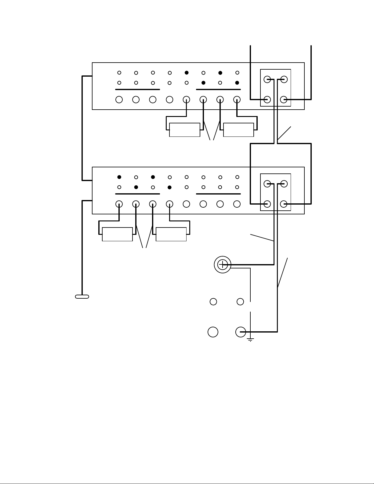
Refer to the diagrams that follow for a typical scanner connection. Figure 3-2 is connection
to the 5000-01 for hipot or insulation resistance (IR) tests. Figure 3-3 is connection to the
5000-02 for ground continuity (GC) testing as well as Hipot or IR testing.
WARNING
THE REAR PANEL GROUND LUGS ON ALL INSTRUMENTS (Guardian 5000 and
Scanners) MUST BE INTERCONNECTED
NEVER TOUCH THE TEST LEADS OR THE DEVICE UNDER TEST WHEN THEY
ARE CONNECTED TO THE INSTRUMENT AND THE RED DANGER LIGHT IS
ON OR BLINKING.
Maintenance & Calibration 3-15
Page 50
To Scanner
3 thru 8
To rear panel
Scan I/P
G17
Control
cable
To rear panel
Scan O/P
To rear panel
Scan I/P
H.V
LOW
H.V
LOW
Under Test
12
12
Device
34
OUTPUT
Device
Under Test
G21,
(orange) to alligator
clip (red)
34
OUTPUT
Device
Under Test
6
5
Sheathed banana plug
5
7
Under Test
6
7
HV plug to sheathed
G18,
banana plug
Device
8
8
(red)
H.VLOW
H.VLOW
I/P
Scanner
#2
O/P
Banana plug cables
Scanner
I/P
#1
O/P
Sheathed banana plug
G21,
G17
Control
cable
To Guardian 5000
rear panel scan
connector
(orange) to alligator
clip (red)
Guardian 5000
Output Connectors
5000-01 Scanner Connection
(one, two or more scanners)
HIGH-VOLTAGE
Figure 3-2
UNKNOWN
HIGH LOW
SENSE
DRIVER
WV
Banana plug (with
G19,
retaining bracket) to
sheathed banana plug
(black)
Maintenance & Calibration 3-16
Page 51

SCAN I/F
GROUNDING
INPUT
Driver
Sense
CHANNEL 1 CHANNEL 2
CHANNEL 3
CHANNEL 4
To front panel
HV I/P
I/P O/P
Device
Under Test
G17
Control cable
G18, HV plug to
sheathed banana (red)
G20
Interconnect cable
banana plug/lug
(red/black)
Device
Under Test
G15, Ground continuity
clip lead set (red/black)
HIGH-VOLTAGE
UNKNOWN
HIGH LOW
SENSE
WV
To Guardian 5000
rear panel scan
connector
DRIVER
Guardian 5000
Output Connectors
Figure 3-3: 5000-02 Scanner Connection
3.3.4 Scanner Programming
There are 16 indicators (8 high, 8 low) on the scanner front panel, during test these indicate
which are programmed for the High Voltage or Low connections. Connections for high
voltage are indicated in red and low in green. When the scanner and Guardian 5000 are
connected (25 pin interconnect cable) the instrument will accept entry of scanner connections.
A Hi or Lo entry (as shown below) is made during the programming process preceding the
entry of a test voltage. It is possible to have one or multiple entries for scanner connections,
i.e. if 1 2 and 3 are entered for the Hi connection all three outputs will be connected to the
High Voltage terminal during the test. When making multiple entries for a scanner
connection up to four will be shown on the Voltage display and those in excess of four shown
on the Limit display.
Maintenance & Calibration 3-17
Page 52

r
Programmed Scanner Connections as Shown in Figure 3-2
When using more than one scanner the initial parameter setting, St-b must be setup for the
number of scanners connected. Refer to paragraph 2.9. Connection of up to 8 scanners
(5000-01 thru 5000-04) for a total of 64 channels, hipot or IR testing or up to 8 scanners
(5000-02 & 5000-04) for a total of 32 channels, ground continuity testing. When
programming scanner connections the scanner number ( 1 thru 8) is shown on the timer
display.
Note
When the scanner is programmed for multiple connections in the same test step the devices
under test are connected in parallel (as shown in Figures 3-3 and 3-3). To test several devices
independent from each other, requires an individual test step (1 to 15) for each. Refer to
paragraph 2.5
Scanner #1
Scanner outputs programmed high
(up to 4)
Scanner outputs programmed high
((those in excess of 4)
STEP
Hi
>R
W-ACV
W-DCV
I-R
13
A
HI
KV
AC
DC
LO
ARC
V
>m
uA
M >
TIMER
mA
TEST
>G
RAMP
Scanner numbe
STEP
Lo 1
>R
W-ACV
W-DCV
I-R
2
4
A
HI
KV
AC
DC
LO
ARC
V
>m
uA
M >
TIMER
mA
TEST
>G
RAMP
Scanner #2
STEP
Hi 2
>R
W-ACV
W-DCV
I-R
57
A
HI
KV
AC
DC
LO
ARC
V
>m
uA
M >
TIMER
mA
TEST
>G
RAMP
STEP
Lo
>R
W-ACV
W-DCV
I-R
68
A
HI
KV
AC
DC
LO
ARC
V
>m
uA
M >
TIMER
mA
TEST
>G
RAMP
Programmed Scanner Connections as Shown in Figure 3-3
STEP
Hi
>R
W-ACV
W-DCV
I-R
14
A
HI
KV
AC
DC
LO
ARC
V
>m
uA
M >
TIMER
mA
TEST
>G
RAMP
SEC
1
SEC
SEC
SEC
2
SEC
1
Maintenance & Calibration 3-18
Page 53

)
3.4 G16 International Power Strip
The G16 International Power Strip allows connection of standard corded products from
several different countries. These being:
Switzerland
Italy
Continental Europe
United States
Denmark
United Kingdom
Australia
Refer to Figure 3-4 for connection of the G16 International Power Strip to the Guardian 5000.
HIGH-VOLTAGE
UNKNOWN
HIGH LOW
SENSE
DRIVER
WV
White
Black
Green
Green/Yellow
(Chassis ground, can also be connected to chassis
ground connector of Guardian 5000 rear panel
G16 International Power Strip
Figure 3-4
G16 International Power Strip Connection
Maintenance & Calibration 3-19
Page 54

Page 55

Section 4 Maintenance & Calibration
4.1 General
Our warranty (at the front of the manual) attests the quality of materials and workmanship in
our products. If malfunction should be suspected, or other information be desired
applications engineers are available for technical assistance. Application assistance is
available in the U.S. by calling 978-461-2100 and asking for Applications Support. For
support outside of the United States please contact your local QuadTech distributor.
4.2 Instrument Return
Before returning an instrument to QuadTech for service please call our Service Department at
800-253-1230 for return material authorization. It will be necessary to include a Purchase
Order Number to insure expedient processing, although units found to be in warranty will be
repaired at no-charge. For any questions on repair costs or shipment instructions please
contact our Service Department at the above number. To safeguard an instrument during
storage and shipping please use packaging that is adequate to protect it from damage, i.e.,
equivalent to the original packaging and mark the box "Delicate Electronic Instrument".
Return material should be sent freight prepaid, to:
QuadTech, Inc.
5 Clock Tower Place, 210 East
Maynard, MA 01754-2530
Attention: Service Department
Shipments sent collect can not be accepted.
4.3 Calibration
Calibration of the Guardian 5000 is recommended on an annual basis. If the unit is returned
to QuadTech for factory calibration refer to paragraph 4.2 for instructions. Using the
calibration procedure below the instrument can be calibrated by a qualified service person if
traceable calibration equipment and standards are available. The instrument should be
powered up for a minimum of 1 hour before calibration to ensure maximum stability.
Maintenance & Calibration 4-1
Page 56

Table 3-1
Equipment for Calibration
Description Requirements
AC/DC Voltmeter Measure range, 0 to 5KV, 0.1%.
AC/DC Current Meter Measure range, 0 to 6KV, 0.1%.
10 MΩ Load Resistor 0.25W
420 kΩ Load Resistor 5W
80 kΩ Load Resistor 25W
50 kΩ Load Resistor 50W
0.1 Ω Load Resistor 100W
0.05 Ω Resistor 5W
4.3.1 Calibration Procedure
The following calibrations procedures are included:
Voltage Calibration
CL 50 OFST ACV ; ACV 50 volts offset
CL 4000 FULL ACV ; ACV 4000 volts full scale
CL 50 OFST DCV ; DCV 50 volts offset
CL 4000 FULL DCV ; DCV 4000 volts full scale
CL 50 OFST IR ; IR 50 volts offset
CL 1000 FULL IR ; IR 1000 volts full scale
Current Calibration
CL OFST 2.99 ACV ; ACV 2.99 mA range offset
CL FULL 2.99 ACV ; ACV 2.99 mA range full scale
CL OFST 30.0 ACV ; ACV 30 mA range offset
CL FULL 30.0 ACV ; ACV 30 mA range full scale
CL OFST 2.99 DCV ; DCV 2.99 mA range offset
CL FULL 2.99 DCV ; DCV 2.99 mA range full scale
CL OFST 15.0 DCV ; DCV 15 mA range offset
CL FULL 15.0 DCV ; DCV 15 mA range full scale
Ground Continuity Calibration
CL 3.0 OFST GrA ; Grounding Current offset
CL 25.00 FULL GrA ; Grounding Current full scale
CL 5.0 OFST GrV ; Grounding Voltage offset
CL 30.0 FULL GrV ; Grounding Voltage full scale
Maintenance & Calibration 4-2
Page 57

To enable calibration:
With the instrument in standby status (Stop button previously pressed and no lights blinking)
remove the front panel calibration seal and push (using pen or pencil point) the recessed
switch through the hole in the front panel (to the in
Press ENTER and then [7] [9] [3] [1]
Display CAL OFF / CAL ON / CAL TEST
CAL OFF : calibration data install zero
CAL ON : calibration finished, in normal operation
CAL TEST : into calibration procedure
Press [OFF] key : to change CAL OFF / CAL ON / CAL TEST
Display CAL TEST : ready to calibrate
Press [PROG] key : ready for calibration
4.3.2 AC Voltage Calibration
Connect the AC voltmeter between the H.V. OUTPUT and the LOW DRIVER terminal.
Press [UP] or [DOWN] key as necessary to display
Display CL 50 OFST ACV
Press [OFF] key to display
Display 1 0.05KV .500mA 0.0 sec
Press [STOP] [START] ; read out the HV meter value
; example 0.062KV
Press [0] [.] [0] [6] [2] [ENTER]
Press [STOP]
Press [DOWN] key to display
Display CL 4000 FULL ACV
Press [OFF] key to display
Display 1 4.00KV .500mA 0.0 sec
Press [STOP] [START] ; read out the HV meter value
; example 4.052KV
Press [4] [.] [0] [5] [2] [ENTER]
Press [STOP] ; stop ACV full scale calibration
position).
Maintenance & Calibration 4-3
Page 58

4.3.3 DC Voltage Calibration
Connect the DC voltmeter between the H.V. OUTPUT and the LOW DRIVER terminal.
Press [UP] or [DOWN] key as necessary to display
Display CL 50 OFST DCV
Press [OFF] key to display
Display 1 0.05KV .500mA 0.0 sec
Press [STOP] [START] ; read out the HV meter value
; example 0.062KV
Press [0] [.] [0] [6] [2] [ENTER]
Press [STOP] ; stop DCV offset calibration
Press [DOWN] key to display
Display CL 4000 FULL DCV
Press [OFF] key to display
Display 1 4.00KV .500mA 0.0 sec
Press [STOP] [START] ; read out the HV meter value
; example 4.052KV
Press [4] [.] [0] [5] [2] [ENTER]
Press [STOP] ; stop DCV full scale calibration
4.3.4 IR Voltage Calibration
Connect the DC voltmeter between the H.V. OUTPUT and the LOW DRIVER terminal.
Press [UP] or [DOWN] key as necessary to display
Display CL 50 OFST IR
Press [OFF] key to display
Display 1 50V 1MΩ 0.0 sec
Press [STOP] [START] ; read out the HV meter value
; example 62V
Press [6] [2] [ENTER]
Press [STOP] ; stop IR voltage offset calibration
Press [DOWN] key to display
Display CL 1000 FULL IR
Press [OFF] key to display
Display 1 1000V 1MΩ 0.0 sec
Press [STOP] [START] ; read out the HV meter value
; example 1052V
Press [1] [0] [5] [2] [ENTER]
Press [STOP] ; stop IR full scale calibration
Maintenance & Calibration 4-4
Page 59

4.3.5 AC Current Calibration
Connect a load resistor (10 Mohms) between the Hipot H.V. OUTPUT of the Guardian 5000
and the High terminal of the AC ammeter. Connect the Low terminal of the AC ammeter to
the LOW DRIVER terminal (black) of the Guardian 5000.
Press [UP] or [DOWN] key as necessary to display
Display CL OFST 2.99 ACA
Press [OFF] key to display
Display 1 1.2KV 2.999mA 0.0 sec
Press [STOP] [START] ; read out the ammeter value
; example 0.124mA
Press [0] [.] [1] [2] [4] [ENTER]
Press [STOP] ; stop ACA 2.99mA range offset
calibration and change the dummy load
resistor to 420 kohms
Press [DOWN] key to display
Display CL FULL 2.99 ACA
Press [OFF] key to display
Display 1 1.2KV 2.999mA 0.0 sec
Press [STOP] [START] ; read out the ammeter value*
; example 2.903A
Press [2] [.] [9] [0] [3] [ENTER]
Press [STOP] ; stop ACA 2.99mA range full scale
calibration
* it may be necessary to
Press [DOWN] key to display add resistance in series
Display CL OFST 30.0 ACA with the load to maintain
Press [OFF] key to display current below the limit
Display 1 1.2KV 30.0mA 0.0 sec
Press [STOP] [START] ; read out the ammeter value
; example 2.903mA
Press [2] [.] [9] [0] [3] [ENTER]
Press [STOP] ; stop ACA 30.0mA range offset
calibration and change the dummy load
resistor to 50 kohms
Press [DOWN] key to display
Display CL FULL 30.0 ACA
Press [OFF] key to display
Display 1 1.2KV 30.0mA 0.0 sec
Press [STOP] [START] ; read out the ammeter value*
; example 24.50mA
Press [2] [4] [.] [5] [0] [ENTER]
Press [STOP] ; stop ACA 30mA range full scale
calibration
Maintenance & Calibration 4-5
Page 60

4.3.6 DC Current Calibration
Connect a load resistor (10 Mohms) between the Hipot H.V. OUTPUT of the Guardian 5000
and the High terminal of the DC ammeter. Connect the Low terminal of the DC ammeter to
the LOW DRIVER terminal (black) of the Guardian 5000.
Press [UP] or [DOWN] key as necessary to display
Display CL OFST 2.999 DCA
Press [OFF] key to display
Display 1 1.2KV 2.999mA 0.0 sec
Press [STOP] [START] ; read out the ammeter value
; example 0.124mA
Press [0] [.] [1] [2] [4] [ENTER]
Press [STOP] ; stop DCA 2.99mA range offset
calibration and change the dummy load
resistor to 420 kohms
Press [DOWN] key to display
Display CL FULL 2.999 DCA
Press [OFF] key to display
Display 1 1.2KV 2.999mA 0.0 sec
Press [STOP] [START] ; read out the ammeter value*
; example 2.903A
Press [2] [.] [9] [0] [3] [ENTER]
Press [STOP] ; stop DCA 2.99mA range full scale
calibration
Press [DOWN] key to display
Display CL OFST 15.0 DCA
Press [OFF] key to display
Display 1 1.2KV 15.00mA 0.0 sec
Press [STOP] [START] ; read out the ammeter value
; example 2.903mA
Press [2] [.] [9] [0] [3] [ENTER]
Press [STOP] ; stop DCA 15.0mA range offset
calibration and change the dummy load
resistor to 80 kohms
Press [DOWN] key to display
Display CL FULL 15.0 DCA
Press [OFF] key to display
Display 1 1.2KV 15.00mA 0.0 sec
Press [STOP] [START] ; read out the ammeter value*
; example 14.02mA
Press [1] [4] [.] [0] [2] [ENTER]
Press [STOP] ; stop DCA 15mA range full scale
calibration
Maintenance & Calibration 4-6
Page 61

4.3.7 GC Calibration
Connect a 4 terminal load resistor (0.1 ohms) between the HIGH/LOW DRIVER and
HIGH/LOW SENSE of the Guardian 5000. Connect the 30 A AC ammeter in series with the
HIGH DRIVER terminal.
Press [UP] or [DOWN] key as necessary to display
Display CL 3.0 OFST GrA
Press [OFF] key to display
Display 1 3.0A 200.0 0.0 sec
Press [STOP] [START] ; read out the ammeter value
; example 2.87A
Press [2] [.] [8] [7] [ENTER]
Press [STOP] ; stop GrA offset calibration
Press [DOWN] key to display
Display CL 25.0 FULL GrA
Press [OFF] key to display
Display 1 25.0A 200.0 0.0 sec
Press [STOP] [START] ; read out the ammeter value
; example 24.87A
Press [2] [4] [.] [8] [7] [ENTER]
Press [STOP] ; stop GrA full scale calibration
Change the load resistor to 50 mΩ and connect the AC voltmeter between HIGH and LOW
SENSE.
Press [DOWN] key to display
Display CL 5.0 OFST GrV ; 5.0A into 50mohm
Press [OFF] key to display
Display 1 5.0A 200.0 0.0 sec
Press [STOP] [START] ; read out the voltmeter value
; example 0.257 volts
Press [0] [.] [2] [5] [7] [ENTER]
Press [STOP] ; stop GrA offset calibration
Change the load resistor to 100 mΩ
Press [DOWN] key to display
Display CL 30.0 FULL GrV ; 30A into 100mohm
Press [OFF] key to display
Display 1 30.0A 200.0 0.0 sec
Press [STOP] [START] ; read out the voltmeter value
; example 2.847 volts
Press [2] [.] [8] [4] [7] [ENTER]
Press [STOP] ; stop GrA full scale calibration
Maintenance & Calibration 4-7
Page 62

4.3.8 Finalize Calibration
Press ENTER and then [7] [9] [3] [1]
Display CAL OFF / CAL ON / CAL TEST
CAL OFF : calibration data install zero
CAL ON : calibration finished, in normal operation
CAL TEST : into calibration procedure
Press [OFF] key : to change CAL OFF / CAL ON / CAL TEST
Display CAL ON : calibration finish, in normal operation
Press [PROG] key : finish calibration
Press the lock switch (to the out position) and cover with a calibration label.
Maintenance & Calibration 4-8
 Loading...