

Page 1

1855
Capacitor Leakage Current/IR Meter
Instruction Manual
Form 150767/A4
©QuadTech, Inc., 2004
5 Clock Tower Place, 210 East
Maynard, Massachusetts, U.S.A. 01754
October 2006
Telephone 978-461-2100
Sales 800-253-1230
Facsimile 978-461-4295
Website www.quadtech.com
The material in this manual is for informational purposes only and is subject to change, without notice.
QuadTech assumes no responsibility for any error or for consequential damages that may result from the
misinterpretation of any procedures in this publication.
CAUTION
Voltage may be present on front and rear panel terminals. Follow all warnings in this manual when
operating or servicing this instrument. Substantial levels of energy may be stored in capacitive devices
tested by this unit.
!
Product will be marked with this symbol (ISO#3864) when it is necessary for the user to refer to
the instruction manual in order to prevent injury or equipment damage.
Product marked with this symbol (IEC417) indicates presence of direct current.
Product will be marked with this symbol (ISO#3864) when voltages in excess of 1000V are
present.
Page 2

Page 2 of 76
Page 3

Contents
Warranty ....................................................................................................................5
Specifications ....................................................................................................................7
Accessories ....................................................................................................................11
Safety Precautions...............................................................................................................13
Condensed Operating Instructions....................................................................................15
Introduction - Section 1
1.1 Unpacking and Inspection........................................................................................ 19
1.2 Product Overview .................................................................................................... 19
1.3 Controls and Indicators............................................................................................ 20
1.3.1 Front Panel Controls and Indicators .......................................................... 20
1.3.2 Rear Panel Controls and Connectors .........................................................21
1.4 Installation .............................................................................................................. 22
1.4.1 Dimensions ................................................................................................. 22
1.4.2 Instrument Positioning................................................................................ 22
1.4.3 Power Requirements ................................................................................... 22
1.4.4 Safety Inspection......................................................................................... 23
Operation - Section 2
2.1 Terms and Conventions ........................................................................................... 25
2.2 Start-Up.................................................................................................................... 27
2.3 SYSTEM SETUP ...................................................................................................27
2.3.1 Calibration ................................................................................................. 27
2.3.2 Memory Manage ........................................................................................ 27
2.3.3 System Configuration ................................................................................28
2.3.3.1 Test Parameter ........................................................................... 29
2.3.3.2 Beeper ........................................................................................ 29
2.3.3.3 Sound Mode ............................................................................... 29
2.3.3.4 Alarm Mode ............................................................................... 30
2.3.3.5 Trig Delay .................................................................................. 30
2.3.3.6 Trig Edge ................................................................................... 30
2.3.3.7 Handler Mode ............................................................................ 31
2.3.3.8 Contrast ...................................................................................... 31
2.3.3.9 GPIB Address ............................................................................ 31
2.3.3.10 RS232 Baud Rate ...................................................................... 32
2.3.3.11 Key Lock ................................................................................... 32
2.3.3.12 Line Frequency .......................................................................... 33
2.3.3.13 Charge Time .............................................................................. 33
2.3.3.14 Range Dwell .............................................................................. 33
2.3.3.15 Average ...................................................................................... 34
2.3.3.16 EXT Vm Display ....................................................................... 34
Page 3 of 76
Page 4

Contents
Operation - Section 2 – Continued
2.4 MAIN INDEX ........................................................................................................ 35
2.4.1 Sequence Test ............................................................................................35
2.4.2 Step Test .................................................................................................... 36
2.4.3 Null ............................................................................................................36
2.4.4 W.V. Test ................................................................................................... 38
2.4.5 Compare .....................................................................................................39
2.5 MEAS DISPLAY .................................................................................................... 41
2.5.1 Test Voltage ............................................................................................... 42
2.5.2 Constant Current ........................................................................................42
2.5.3 Range .........................................................................................................43
2.5.4 Charge Time ............................................................................................... 44
2.5.5 Dwell Time ................................................................................................. 44
2.5.6 Speed...........................................................................................................45
2.5.7 Trigger .......................................................................................................45
2.5.8 Rated Withstand Voltage (Vf) ................................................................... 46
2.5.9 Measurement Time (Tend) ........................................................................ 46
2.5.10 Maximum Charge Time (CHG Tend) ........................................................ 47
2.6 Connection to Device under Test............................................................................. 48
2.7 Measurement Procedure........................................................................................... 49
Interface - Section 3
3.1 RS-232 Interface ..................................................................................................... 51
3.1.1 RS232 Pin Configuration ........................................................................... 51
3.1.2 RS232 Specifications ................................................................................. 51
3.1.3 RS232 Commands .....................................................................................52
3.2 IEEE-488 Interface .................................................................................................. 53
3.2.1 Pin Configuration........................................................................................ 53
3.2.2 IEEE-488 Interface Function Codes and Messages.................................... 55
3.2.3 IEEE-488 Interface Commands .................................................................. 57
3.2.4 IEEE-488 Command Format .....................................................................59
3.2.5 IEEE-488 Commands - Detailed ............................................................... 60
3.2.6 Error Messages .......................................................................................... 71
3.3 Handler Interface .................................................................................................... 72
3.3.1 Trigger ....................................................................................................... 73
3.3.2 Handler Pin Assignments for Compare Operation .................................... 74
Service & Calibration - Section 4
4.1 General ................................................................................................................... 75
4.2 Instrument Return .................................................................................................... 75
4.3 Calibration ............................................................................................................... 75
4.3.1 1855 Verification Procedure ...................................................................... 76
4.3.2 1855 Verification Data Sheet ..................................................................... 76
Page 4 of 76
Page 5

Warranty
QuadTech warrants that Products are free from defects in material and workmanship and, when
properly used, will perform in accordance with QuadTech’s applicable published specifications.
If within one (1) year after original shipment it is found not to meet this standard, it will be
repaired, or at the option of QuadTech, replaced at no charge when returned to a QuadTech
service facility.
Changes in the Product not approved by QuadTech shall void this warranty.
QuadTech shall not be liable for any indirect, special or consequential damages, even if
notice has been given of the possibility of such damages.
This warranty is in lieu of all other warranties, expressed or implied, including, but not
limited to any implied warranty or merchantability of fitness for a particular purpose.
SERVICE POLICY
QuadTech’s service policy is to maintain product repair capability for a period of at least five (5)
years after original shipment and to make this capability available at the then prevailing schedule
of charges.
Page 5 of 76
Page 6

Page 6 of 76
Page 7

Specifications
Leakage Current Test:
Leakage Current: 0.001uA – 20.0mA
Accuracy: ±(0.3% + 0.005uA)
Test Voltage: 1.0V – 650V DC, 0.1V/Step
Voltage Accuracy: ±(0.5% + 0.2V)
Test Current: 0.5mA – 500mA, 0.5mA/Step for DCV ≤ 100V
0.5mA – 150mA, 0.5mA/Step for DCV > 100V
Charge Current Accuracy: ±(3% + 0.05mA)
Insulation Resistance Test:
Insulation Resistance: 10Ω – 99.99GΩ
IR Accuracy:
20V
+
++ +0.6
Vm
0.5uA
Im
Where Vm and Im are measured voltage & current for a giv en load.
Test Voltage: 1.0V – 650V DC, 0.1V/Step
Voltage Accuracy: ±(0.5% + 0.2V)
Test Current: 0.5mA – 500mA, 0.5mA/Step for DCV ≤ 100V
0.5mA – 150mA, 0.5mA/Step for DCV > 100V
Charge Current Accuracy: ±(3% + 0.05mA)
Withstand Voltage Test:
Rise Time (Tr): 0.05s – 120s
Withstand Voltage (Vf): 1.0V – 650V DC, 0.1V/Step
Test Current: 0.5mA – 150mA, 0.5mA/Step
Charge Current Accuracy: ±(3% + 0.05mA)
Measure Time: 30s – 600s
MAX Charge Time: 5s – 600s
0.005uA
1
Im
%
Page 7 of 76
Page 8

Specifications (Continued)
General Features
Test Types: Automatic Sequence Test
Manual Step Test
Null: Correction for Lead Leakage
Monitored Voltage (Vm): 1.0V – 650V DC (Voltage across DUT)
Charge Time: 0 – 999seconds in 1s/10s increments <100s; 100s increments >100s
Delay Time: 0.2 – 999seconds in 0.1s increments <100s; 10s increments>100s
Discharge: 65 Watt Discharge Circuit
Trigger: Delay: 0 – 9.995 seconds in 0.1s increments
Edge: Falling or Rising
Measurement Mode: Continuous or Trigger (INT, EXT or Manual)
Measurement Rate: Fast: 18 measurements/second
Medium: 14 measurements/second
Slow: 7 measurements/second
Ranging: Automatic or Hold
Averaging: 1-8 measurements
Compare: Set Upper & Lower Limits for LC and IR Tests
Display: 240 x 64 LCD Graphic display
Indication: Audible alarm programmable HI, LOW or OFF for Pass or Fail
Standard Interface: RS232
Optional Interfaces: IEEE-488 & Handler
Connectors: 1 BNC terminal: Input
2 Banana terminals: HV (+), HV (-)
1 Banana Socket: Chassis Ground
Front Panel Lockout: Keypad Lock
Page 8 of 76
Page 9

Specifications (Continued)
Mechanical: Bench Mount
Dimensions: (w x h x d): 12.50 x 4.00 x 13.50 inches
317.2 x 101.5 x 342.6 mm
Weight: 18 lbs (8.2kg) net, 22 lbs (10kg) shipping
Environmental: Operating: 10°C to 40
Storage: -10°C to 50
Humidity: <90%
Pollution Degree 2
Installation Category I
Power: • 90-125VAC • 190-250VAC
• 50 or 60Hz • 400W max
Supplied: • Instruction Manual • Power Cable
• Calibration Certificate • Lead Set
Ordering Information: Description Catalog No.
Capacitor Leakage Current/IR Meter 1855
o
C
o
C
Page 9 of 76
Page 10

Page 10 of 76
Page 11

Accessories
Accessories Included
Item Quantity QuadTech P/N
AC Power Cord 1 4200-0300
Power Line Fuse: 4A 250V SB for 115V operation 1 520149
Power Line Fuse: 2A 250V SB for 230V operation 1 520148
Test Leads: Banana to Alligator Clip & BNC to Alligator Clip 1 1855-01
Instruction Manual 1 150767
Calibration Certificate 1 N/A
Accessories/Options Available
Item Quantity QuadTech P/N
IEEE-488 & Handler Interface 1 700171
RS-232 Cable 1 630157
Resistivity Test Cell for Surface & Volume Resistivity Msmts 1 1855-11
Page 11 of 76
Page 12

Page 12 of 76
Page 13

Safety Precautions
CAUTION
The 1855 Capacitor Leakage Current/IR Meter can provide an output voltage of 650V DC to the
device under test (DUT). Although the 1855 unit is a low voltage instrument, some devices
(especially capacitors) can store charge when tested. If not discharged properly, these devices
may cause serious hazards. Follow these safety instructions.
1. Operate the 1855 unit with its chassis connected to earth ground. The instrument is
shipped with a three-prong power cord to provide this connection to ground. This power
cord should only be plugged in to a receptacle that provides earth ground. Serious injury
can result if the 1855 unit is not connected to earth ground.
2. Tightly connect BNC cable to the silver INPUT terminal. If this is not done, the DUT’s
casing can be charged to the high voltage test level and injury or electrical shock hazards
could result if the DUT is touched.
3. Never touch the test leads, test fixture or DUT in any manner (this includes insulation on
all wires and clips) when [TRIGGER] has been pressed and the output is applied.
4. Before turning on the 1855 instrument, make sure there is no device (DUT) or fixture
connected to the test leads.
5. Make sure any capacitive device has been discharged fully before touching the test lead
wires or output terminals.
6. In the case of an emergency, turn OFF the POWER switch using a “hot stick” and
disconnect the AC power cord from the wall. Do not touch the 1855 instrument.
7. Be wary when the 1855 instrument is used in remote control mode. The voltage/current
output is being turned on and off with an external signal.]
8. Do not exceed the 1A Maximum Input Current.
Page 13 of 76
Page 14

Page 14 of 76
Page 15

Condensed Operating Instructions
General Information
The 1855 Capacitor Leakage Current/IR Meter is an instrument for measuring the parameters of
leakage current (LC), insulation resistance (IR), withstand voltage (WV) and rise time (Tr). The
1855 instrument functions mainly as a leakage current and withstand voltage tester for aluminum
foil electrolytic capacitors and high dielectric ceramic capacitors. The 1855 instrument is useful
in testing any components for which leakage current is a major factor including Zener diodes,
absorbers, etc. For production testing, the 1855 instrument has a Compare function and Pass/Fail
indication. Connection to device under test is through BNC/Banana terminals on the front panel.
Start-Up
The 1855 Capacitor Leakage Current/IR Meter can be operated from a power source between 90125V or 190-250V AC at a power line frequency of 50 or 60Hz. The standard 1855 unit is
shipped from QuadTech with a 4A fuse in place for AC 90-125V operation. (A 2A fuse is
included for AC 190-250V operation). The 1855 unit is shipped with the line voltage selector set
for 115V. Refer to paragraph 1.4.3 for instructions on changing the fuse or line voltage selector.
Connect the 1855 Capacitor Leakage Current/IR Meter’s AC power cord to the source of proper
voltage. Operate the 1855 instrument with its chassis connected to earth ground. The 1855
instrument is shipped with a three-prong power cord to provide this connection to ground. This
power cord should only be plugged into a receptacle that provides earth ground. Serious injury
may result if the 1855 instrument is not connected to earth ground.
To turn the 1855 instrument ON, press the power button on the front panel. To switch the power
OFF, press the button again or if measurements are to be made proceed with the Test Parameter
Setup in Table COI-1. The 1855 instrument should warm up for 15 minutes prior to use.
Table COI-1: Test Parameter Setup
Test LC/IR WV/Tr
Parameter
Test V 1.0V – 650V DC N/A
C.C. 0.5mA – 500mA N/A
Range 2uA-20uA-200uA-2mA-20mA N/A
CHG T 0s – 999s N/A
DWELL T 0.2s – 999s N/A
Speed Fast – Medium – Slow N/A
Vf N/A 1.0 – 650V DC
C.C. N/A 0.5mA – 150mA
Tend N/A 30s – 600s
CHG Tend N/A 5s – 600s
NOTE
Refer to paragraphs 2.3.3 through 2.4 for a full description of programming test parameters. Test parameters must
be set before the 1855 instrument can be zeroed.
Page 15 of 76
Page 16

Condensed Operating Instructions (Continued)
There are three main menus within the 1855 instrument software. Familiarize yourself with
these menus prior to programming a test. Figure COI-1 illustrates the MEAS DISPLAY screen
and lists the functions that can be accessed by pressing the [MAIN INDEX] and [SYSTEM
SETUP] keys.
Function of F1 - F4 Keys
MEAS DISPLAY
MAIN
< MEAS DISPLAY: SEQ. TEST >
TEST V.
1.0V
:
F1
MEAS
DISPLAY
INDEX
SYSTEM
SETUP
Lc :
Vm = 0.0V
MEAS
DISPLAY
SEQ. STEP
Test Voltage
Constant Current
Range
NEXT PAGE 1/2
Charge Time
Dwell Time
Speed
NEXT PAGE 2/2
Test Voltage
Constant Current
Range
NEXT PAGE 1/2
Trigger
Speed
NEXT PAGE 2/2
-1.2 A
DISCHARGECHARGE TEST
Sequence Test
Step Test
Null
W.V. Test
Compare
MAIN
INDEX
Test Voltage
Constant Current
Range
Charge Time
Dwell Time
Speed
Test Voltage
Constant Current
Range
Trigger
Speed
Foil Voltage
Constant Current
End Time
Charge End Time
C.C.
RANGE
NEXT PAGE 1/2
:
0.5mA
:
2uA
A
SYSTEM
SETUP
CALIBRATION
Need Password*
MEMORY MANAGE
Need Paasword*
SYSTEM CONFIGURATION
Test Parameter
Beeper
Sound Mode
Alarm Mode
Trigger Delay
Trigger Edge
Handler Mode
Contrast
GPIB Address
RS232 Baud Rate
Key Lock
Line Frequency
Charge Time
Range Dwell
Average
EXT Vm Display
* Qualified Service Personnel Only
Instrument Calibration & Verification
F2
CHARG E/TEST DISCHARGE
F3
F4
TRIGGER
Figure COI-1: 1855 Instrument Menus
NOTE:
The function keys [F1 – F4] are used to select the parameter to change and in some menus to
change the value of that selected parameter.
The function of UP/DOWN depends on the menu. In some menus, the LEFT/RIGHT keys are
used to select a digit by moving the underscored cursor left or right.
Page 16 of 76
Page 17

Condensed Operating Instructions (Continued)
1. Set Test Parameters
• Press [POWER] ON.
• Allow the instrument to warm up for 15 minutes.
• Press [MEAS DISPLAY]
• Set test parameters (voltage, current, range, etc.) using the function & arrow keys.
2. Null
After setting your test parameters, use the Null function of the 1855 instrument to zero the
test leads. With no device connected, connect the appropriate cable to the front panel
BNC/Banana connectors. Refer to paragraph 2.6 for cable connections.
With the instrument in MEAS DISPLAY status:
1. Press [MAIN INDEX]
2. Press [F3] = NULL
3. Press [TRIGGER] button.
4. Wait while instrument cycles through NULL test.
5. Press [MAIN INDEX] to return to MEAS DISPLAY status.
6. Choose Test: [SEQ Test], [STEP Test] or [Next Page] to select [WV Test]
QuadTech
<MEAS. DISPLAY: NULL>
LC : mA
Press TRIGGER to start ...
CHARGE TEST DISCHARGE
01
l
1855 Capacitor Leakage Current /IR Meter
HV
+
OPEN No DUT Connected for NUL L function
-
MAIN
INDEX
TRIGGER
SYSTEM
SETUP
F1
F2
F3
F4
(-)(+)INPUT
F1
F2
F3
F4
MEAS
DISPLAY
CHARGE/TEST DISCHARGE
Figure COI-2: NULL OPEN Configuration
Page 17 of 76
Page 18

Condensed Operating Instructions (Continued)
3. Connection to Device under Test (DUT)
Figure COI-3 illustrates the connection of the 1855 instrument to a DUT using the 1855-01 Lead
Set. For Leakage Current, Insulation Resistance and Withstand Voltage Tests, the red alligator
clip/BNC cable is connected between the silver INPUT terminal on the 1855 unit and the high
side of the device under test. The black alligator clip/banana cable is connected between the
white HV (-) terminal on the 1855 unit and the low side of the DUT.
QuadTech
<MEAS. DISPLAY: SEQ. TEST>
LC :
CHARGE TEST DISCHARGE
01
l
1855 Capacitor Leakage Current /IR Meter
1.5 mA
TEST V
C.C
RANGE
NEXT PAGE 1/2
+
DUT
1.0
:
0.5
:
2
A
:
HV
-
MAIN
INDEX
TRIGGER
SYSTEM
SETUP
V
F1
mA
F2
F3
uA
F4
(-)(+)INPUT
F1
F2
F3
F4
MEAS
DISPLAY
CHARGE/TEST DISCHARGE
COI-3: Connection to DUT for LC Test
4. Make a Measurement
1. Press [MEAS DISPLAY]
2. Connect device under test (DUT) to test leads.
3. Press [TRIGGER].
4. Record measurement.
NOTE
Please read this instruction manual in its entirety before operating this instrument.
These condensed operating instructions are not a substitute for all the information provided in the
remainder of this manual.
Page 18 of 76
Page 19
Section 1: Introduction
1.1 Unpacking and Inspection
Inspect the shipping carton before opening. If damaged, contact the carrier agent immediately.
Inspect the 1855 Capacitor Leakage Current/IR Meter for any damage. If the instrument appears
damaged or fails to meet specifications notify QuadTech (refer to instruction manual front cover)
or its local representative. Retain the original shipping carton and packing material for future use
such as returning the instrument for recalibration or service.
1.2 Product Overview
The 1855 Capacitor Leakage Current/IR Meter is a compact yet powerful LC Tester and IR
meter for production or laboratory testing of aluminum electrolytic capacitors, resistors and other
passive components. The 1855 instrument measures 4 parameters: Leakage Current (LC),
Insulation Resistance (IR), Rise Time (Tr) and Withstand Voltage (Vf) and displays two
simultaneously. Basic accuracy is ±0.3%. From 1-8 measurements can be made, averaged and
the result displayed with the Averaging function. Ranging is automatic or user selectable.
Measurement rate is also selectable (Slow, Medium or Fast) with rates up to 18 measurements
per second. Measurements can be made continuously or triggered with a programmable delay
time up to 10 seconds. The 1855 comes standard with an RS-232 interface. An optional IEEE488 and Handler interface is also available. Voltage across the DUT can be monitored and
displayed. Zero the effects of stray leakage in the test leads with the Null function. The Compare
function on the 1855 instrument has programmable upper and lower limits and displays Pass/Fail
in addition to the measurement value. Connection to the device under test is through 1 BNC
INPUT terminal and 2 Banana HV terminals on the front panel.
QuadTech
<MEAS. DISPLAY: SEQ. TEST>
LC :
CHARGE TEST DISCHARGE
01
l
1855 Capacitor Leakage Current /IR Meter
:
1.0
:
0.5
:
2
A
HV
+
-
1.5 mA
TEST V
C.C
RANGE
NEXT PAGE 1/2
MEAS
MAIN
V
F1
mA
F2
F3
uA
F4
(-)(+)INPUT
F1
F2
F3
F4
DISPLAY
CHARGE/TEST DISCHARGE
INDEX
TRIGGER
SYSTEM
SETUP
Figure 1-1: 1855 Capacitor Leakage Current/IR Meter
Introduction Page 19 of 76
Page 20

1.3 Controls and Indicators
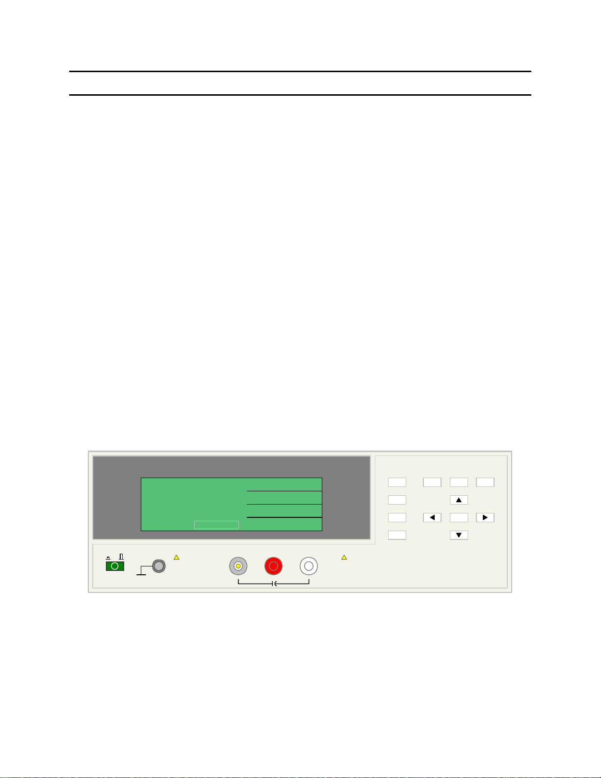
1.3.1 Front Panel Controls and Indicators
Figure 1-2 illustrates the controls and indicators on the front panel of the 1855 Capacitor
Leakage Current/IR Meter instrument. Table 1-1 identifies them with description and function.
10 9 811
QuadTech
<MEAS. DISPLAY: SEQ. TEST>
LC :
CHARGE TEST DISCHARGE
01
l
1 423 56
1855 Capacitor Leakage Current /IR Meter
1.5 mA
TEST V
C.C
RANGE
NEXT PAGE 1/2
+
1.0
:
0.5
:
2
A
:
HV
-
MEAS
MAIN
V
F1
mA
F2
F3
uA
F4
(-)(+)INPUT
F1
F2
F3
F4
DISPLAY
CHARGE/TEST DISCHARGE
INDEX
TRIGGER
SYSTEM
SETUP
7
Figure 1-2: 1855 Front Panel Controls & Indicators
Table 1-1: 1855 Front Panel Controls & Indicators
Reference #
Figure 1-2
1 Green Push Button Apply AC POWER: 1=ON, 0=OFF
2 Silver Banana Jack Chassis ground connection
3a INPUT Silver BNC terminal Current Drive Terminal, High (+)
3b HV (+) Red Banana Jack Voltage Sense Terminal, High (+)
3c HV (-) White Banana Jack Voltage Sense Terminal, Low (-)
4 F1, F2, F3 and
5 ◄, ▼, ►, ▲ 4 gray push buttons Move backlit box around display to choose parameter
6 TRIGGER Gray push button Initiate measurement
7 DISCHARGE STOP measurement in progress & initiate discharge time
8 SYSTEM
9 MAIN
10 MEAS
11 240 x 64 LCD
Name Type Function
4 gray push buttons Select Instrument Functions
F4
Keys perform different functions under different menus.
Right side of display shows corresponding key function.
Change parameter value (increase/decrease)
Gray push button View, Select or Change System Parameters:
SETUP
Parameter, Beeper, Sound, Alarm, Trigger, Handler,
Contrast, GPIB, RS-232, Key Lock, Line Frequency,
Charge, Dwell, Average & EXT Vm Display
Gray push button View, Select or Change Setup & Result Parameters:
INDEX
Sequence, Step, Null, WV Test & Compare
Gray push button View, Select or Change Measurement Parameters:
DISPLAY
Voltage, Current, Range, Charge, Dwell, Speed & Trigger
Show measurement results as value or pass/fail.
display
Show programming instructions
Page 20 of 76 Introduction
Page 21

1.3.2 Rear Panel Controls and Connectors
Figure 1-3 illustrates the controls and connectors on the rear panel of the 1855 Capacitor Leakage
Current/IR Meter instrument. Table 1-2 identifies them with description and function.
56
115V ~/230V~
RS232
WARNING:
!
!
IEEE-488 INTERFACEHANDLER INTERFACE
FOR CONTI NUED PROTECTION
AGAINST FIRE HAZARD, REPLACE ONLY
WITH THE SAME TYPE AND RATING OF FUSE
AS SPECIFIED FOR THE LINE VOLTAGE
BEING UTILIZED.
CAUTION:
NO OPERATO R SERVICEABLE
PARTS INSIDE. REFER SERVICING TO
QUALIFIED PERSONNEL.
POLLUTION DEGREE 2
INSTALLATION CATEGORY I
MODEL NO.
SERIAL NO.
50/60Hz 400VA MAX
FUSE LINE VOLTAGE
SELECTED
115V
230V
115V
90V - 125V~
T4.0AL 250V
190V - 250V~
T2.0AL 250V
1
234
Figure 1-3: Rear Panel 1855 Instrument
Table 1-2: 1855 Rear Panel Controls & Connectors
Reference #
Figure 1-3
1 HANDLER
2 IEEE-488
3 FUSE Black screw cap fuse
4 LINE VOLTAGE
5 AC Line Input Black 3-wire inlet
6 RS-232
Name Type Function
Blue 24-pin
INTERFACE
connector
Blue 24-pin
INTERFACE
connector
holder
2 Red 2-position
SELECTED
Slide Switches
module
Black 9-pin RS-232 interface for serial communication
INTERFACE
Handler Interface connector for remote operation
IEEE-488 Interface connector for data transfer
Short circuit protection
T 4A 250V fuse for 115V operation
T 2A 250V fuse for 230V operation
Select Voltage Level corresponding to AC Source
90V – 125V: T4.0A 250V fuse
190V – 250V: T 2A 250V fuse
Connection to AC power source
Introduction Page 21 of 76
Page 22

1.4 Installation
1.4.1 Dimensions
The 1855 Capacitor Leakage Current/IR Meter unit is supplied in a bench configuration, i.e., in a
cabinet with resilient feet for placement on a table. Flip feet are attached under the front feet so
that the 1855 instrument can be tilted up for convenient operator viewing.
4.0"
101.6mm
QuadTech
01
l
1855 Capacitor Leakage Cur rent/IR Meter
<MEAS. DISPLAY: SEQ. TEST>
Lc : 1.5 mA
TEST V.
C.C
RANGE
NEXT PAGE 1/ 2
HV
0.5mA
MEAS
MAIN
F1
F1
1.0V
F2
F3
2uA
F4
(-)(+)INPUT
DISPLAY
F2
F3
F4
SYSTEM
INDEX
SETUP
TRIGGER
13.5"
342.9mm
14.0"
355.6mm
including
front and
rear
12.50"
connectors
317.50mm
Figure 1-4: 1855 Instrument Dimensions
1.4.2 Instrument Positioning
The 1855 instrument contains one (1) graphic display for direct readout of measured parameters.
The optimum angle for viewing is slightly down and about 10 degrees either side of center. For
bench operation the front flip feet should always be used to angle the instrument up. In bench or
rack mount applications the instrument should be positioned with consideration for ample air
flow around the rear panel fan ventilation hole. An open space of at least 3 inches (75mm) is
recommended behind the rear panel. Testing should be performed on a non-conductive surface.
An ESD mat is not a recommended test platform.
1.4.3 Power Requirements
The 1855 can be operated from a power source of 90 to 125V AC or 190 to 250V AC. Power
connection is via the rear panel through a standard receptacle. Before connecting the 3-wire
power cord between the unit and AC power source, make sure the voltage selection switches on
the rear panel (Figure 1-5) are in accordance with the power source being used. For a 90-125V
source, use a 4A 250V fuse. For a 190-250V source, use a 2A 250V fuse. Always use an outlet
that has a properly connected protection ground.
4.5"
114.3mm
including
feet
Page 22 of 76 Introduction
Page 23
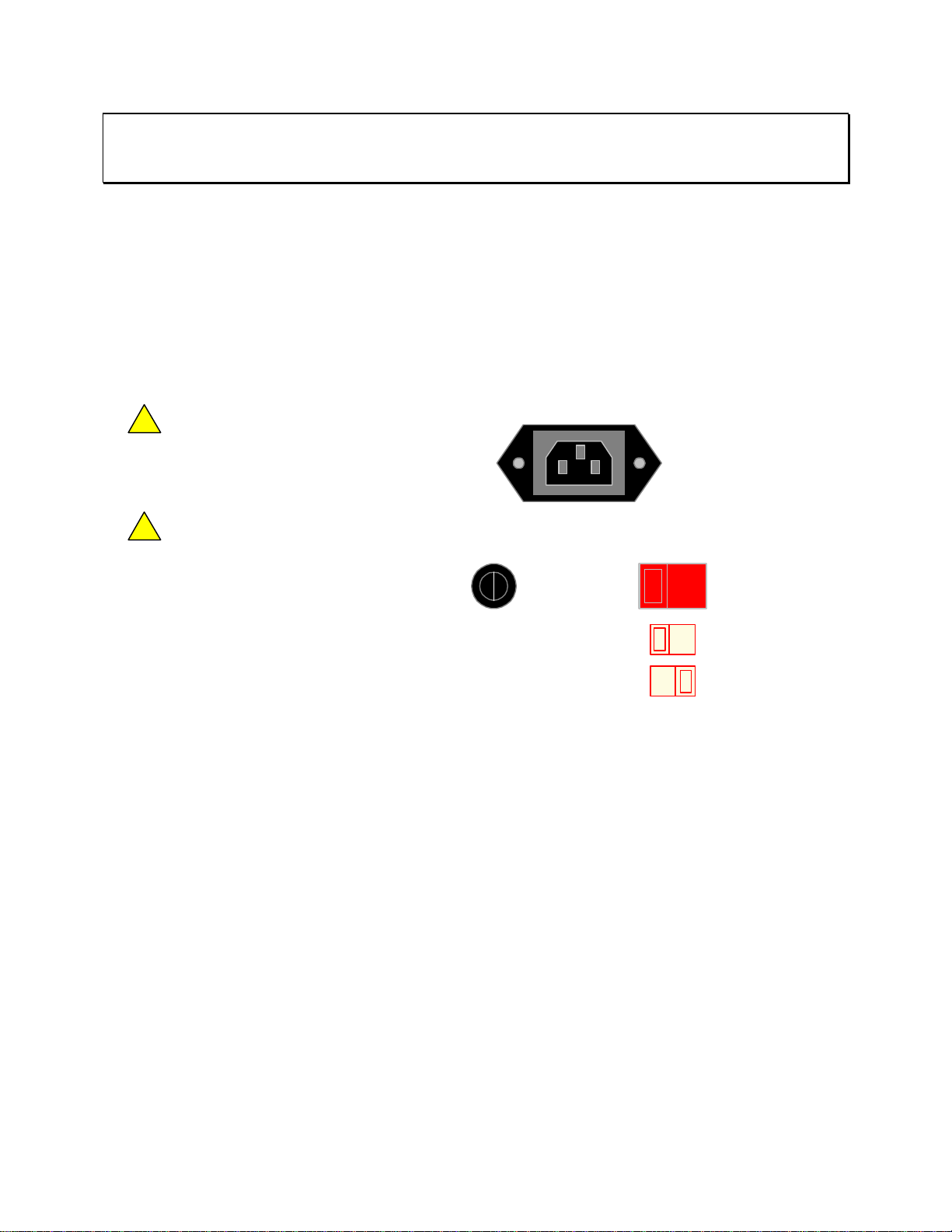
CAUTION
Make sure the unit has been disconnected from its AC power source for at least five minutes
before proceeding.
Procedure for Changing an 1855 Instrument Fuse
Unscrew the fuse cap on the rear panel of the 1855 and pull fuse holder outward.
Once the fuse holder has been removed from the instrument snap the fuse from the holder and
replace. Make sure the new fuse is of the proper rating.
Install the fuse back into the cap holder by pushing in until it locks securely in place.
115V ~/230V~
WARNING:
!
AGAINST FIRE HAZARD, REPLACE ONLY WITH
THE SAME TYPE AND RATING OF FUSE AS
SPECIFIED FOR THE LINE VOLTAGE BEING
UTILIZED.
FOR CONTINUED PROTECTION
50/60Hz 400VA MAX
CAUTION:
!
PARTS INSIDE. REFER SERVICING TO
QUALIFIED PERSONNEL.
POLLUTION DEGREE 2
INSTALLATION CATEGORY I
NO OPERATOR SERVICEABLE
FUSE
LINE VOLTAGE
SELECTED
115V
115V
230V
90V-125V~
T4.0AL 250V
190V-250V~
T2.0AL 250V
Figure 1-5: Close-Up of 1855 Rear Panel
1.4.4 Safety Inspection
Before operating the instrument inspect the fuse holder on the rear of the 1855 instrument to
ensure that the properly rated fuse is in place, otherwise damage to the unit is possible. Make
sure that the voltage selector switches are set in accordance with the power source in use. Refer
to paragraph 1.4.3 and Figure 1-5.
The 1855 instrument is shipped with a standard U.S. power cord, QuadTech P/N 4200-0300
(with Belden SPH-386 socket or equivalent, and a 3-wire plug conforming to IEC 320). Make
sure the instrument is only used with these cables (or other approved international cord set) to
ensure that the instrument is provided with connection to protective earth ground.
The surrounding environment should be free from excessive dust to prevent contamination of
electronic circuits. The surrounding environment should also be free from excessive vibration.
Do not expose the 1855 instrument to direct sunlight, extreme temperature or humidity
variations, or corrosive chemicals.
Introduction Page 23 of 76
Page 24

Page 25

Section 2: Operation
2.1 Terms and Conventions
Table 2-1: Measurement Unit Prefixes
Multiple Scientific Engineering Symbol
1000000000000000 1015 Peta P
1000000000000 1012 Tera T
1000000000 109 Giga G
1000000 106 Mega M
1000 103 Kilo k
.001 10-3 milli m
.000001 10
.000000001 10-9 nano n
.000000000001 10
.000000000000001 10
Capacitor: Abbreviated C. A capacitor is passive component comprised of two conductors
Capacitance: The measure of the ratio of charge on either plate of a capacitor to the potential
Compare: Procedure for sorting components by comparing the measured value against a
DC: Direct Current. Non-reversing polarity. The movement of charge is in one
Dielectric: A material which is an electrical insulator or in which an electric field can be
Dielectric Absorption: The physical phenomenon of insulation appearing to absorb and retain an
Dielectric Constant: Abbreviated K, relative dielectric constant. The dielectric constant of a material
Discharge: The act of draining off an electrical charge to ground. Devices that retain charge
-6
micro µ
-12
pico p
-15
separated by a dielectric. A capacitor stores charge blocks DC flow and allows
AC flow based on frequency and capacitor design.
difference (voltage) across the plates. Unit of measure is the Farad (F).
known standard.
direction. Used to describe both current and voltage. Batteries supply direct
current (DC).
sustained with a minimum dissipation of power.
electrical charge slowly over time. Apply a voltage to a capacitor for an
extended period of time and then quickly discharge it to zero voltage. Leave the
capacitor open circuited for a period of time then connect a voltmeter and
measure the residual voltage. The residual voltage is caused by the dielectric
absorption of the capacitor.
is the ratio of the capacitance of a capacitor filled with a given dielectric to that
same capacitor having only a vacuum as a dielectric.
should be discharged after an IR test or DC hipot test.
femto f
Interface Page 25 of 76
Page 26

DUT: Device Under Test. (i.e. the product being tested).
Ground: The base reference from which voltages are measured, nominally the same
potential as the earth. Ground is also the side of a circuit that is at the same
potential as the base reference.
Insulation Resistance: Measures the total resistance between any two points separated by electrical
insulation. The IR test determines how effective the dielectric (insulation) is in
resisting the flow of electrical current.
Interface:
Handler: Device for remote control of test instrument in component handling operations.
IEEE-488: General Purpose Interface Bus (GPIB). GPIB is an industry standard definition
of a Parallel bus connection for the purpose of communicating data between
devices.
RS232: An industry standard definition for a Serial line communication link or port.
Range: The resistance ranges the instrument uses for reference in making the
measurement.
Speed: The rate at which the instrument makes a measurement in measurements per
second. Speed is inversely proportional to accuracy.
Trigger: The device for initiating the test (applying the voltage or current).
External: The test is initiated via an external source such as a computer with an IEEE-488
or Handler interface. One measurement is made each time the external trigger is
asserted on the handler.
Internal: The instrument continuously makes measurements.
Manual: The operator initiates the test by pressing the [START] button. One
measurement is made each time the trigger is pressed.
Withstand Voltage: Voltage at which the product’s insulation begins to break down. There are many
definitions for Withstand Voltage. This manual uses the terminology from the
EIAJ RC-2364A standard, “Test Methods of Electrode Foils for Aluminum
Electrolytic Capacitors”.
Term Symbol Definition
Formation Voltage Vfe The final applied voltage
Standard Dielectric
Withstand Voltage
Rise Time Tr The time between when the current is applied and
Withstand Voltage Vt
Rated Voltage WV Rated working voltage of a capacitor
Vf The withstand voltage of formed foil
the voltage reaches 90% of the rated withstand
voltage, Vf.
Tr + 3minutes ±10seconds (formed foils)
Tr + 1minute ±10seconds (unformed foils)
Page 26 of 76 Interface
Page 27

2.2 Startup
Check to make sure the red Line Voltage Selector switch on the rear panel agrees with the power
source available. Depending on the power source the switch position should be in the up or down
position as shown in Figure 1-5 (Close-Up of 1855 Rear Panel).
CAUTION
USE ALL PRECAUTIONS NECESSARY TO AVOID TOUCHING THE DEVICE UNDER TEST WHEN THE
TRIGGER BUTTON HAS BEEN PRESSED.
Connect the instrument power cord to the source of proper voltage. The instrument is to be
used only with three-wire grounded outlets.
Power is applied to the 1855 instrument by pressing the green power switch on the front panel to
the ON (1 position). The 1855 unit should warm up for a period of at least 15 minutes prior to
measurements being made.
2.3 SYSTEM SETUP
System Setup contains the 1855 instrument setup functions: Calibration, Memory Manage and
System Configuration. Press [SYSTEM SETUP] to access these functions.
F1
< SYSTEM SETUP > CALIBRATION
MEM MANAGE
Enter Calibration
F2
Enter Memory Manage
F3
SYSTEM CONFIG
Enter System Configuration
Figure: 2-1: System Setup
2.3.1 Calibration
The Calibration menu is to be accessed by Qualified Service Personnel Only. Altering the 1855
instrument calibration will void the instrument warranty. The Calibration function is used to
verify the resistance measurement ranges. To access the calibration function, press [SYSTEM
SETUP] then press [F1] = [CALIBRATION]. Enter the password. [▲] [▼] [►] [◄]
[TRIGGER]. Select cal range 20V or 200V. Refer to paragraph 4.3 Calibration for procedure.
2.3.2 Memory Manage
The Memory Manage menu is to be accessed by Qualified Service Personnel Only. Altering the
1855 instrument memory will void the instrument warranty. The memory manage function is
used to verify the setup of the 1855 unit with a Function Test and a Handler Test. To access the
memory manage function, press [SYSTEM SETUP] then press [F2] = [MEM MANAGE]. Enter
the password. [▲] [▼] [►] [◄] [TRIGGER].
Interface Page 27 of 76
Page 28

2.3.3 System Configuration
Prior to programming a test or measuring a device, set up the system controls of the 1855
instrument. To access the system controls, press [SYSTEM SETUP] then press [F3] = [SYSTEM
CONFIG]. Table 2-2 lists the contents of SYSTEM CONFIG.
F1
< SYSTEM SETUP > CALIBRATION
MEM MANAGE
SYSTEM CONFIG
Enter Calibration
F2
Enter Memory Manage
F3
Enter System Configuration
< SYSTEM CONFIG >
TEST PARAMETER :
BEEPER
SOUND MODE
ALARM MODE
TRIG DELAY
TRIG EDGE
HANDLER MODE :
< SYSTEM CONFIG >
CONTRAST :
GPIB ADDRESS
RS232 BAUD RATE
KEY LOCK
LINE FREQUENCY
CHARGE TIME
RANGE DWELL :
< SYSTEM CONFIG >
AVERAGE :
EXT Vm DISPLAY :
L.C.
LOW
:
FAIL
:
PULSE
:
0000 mS
:
FALLING
:
CLEAR
07
:
17
:
19200
:
OFF
:
60Hz
:
Vm = Vs
0.0 S
1
OFF
I.R.
L.C.
DIGIT UP
DIGIT DOWN
DIGIT UP
DIGIT DOWN
F1
Set Test Parameter to IR
F2
Set Test Parameter to LC
F3
F4
F1
Increase brightness: 00 - 15
F2
Decrease brightness: 15 - 00
F3
F4
F1
Increase # to Average: 1 - 8
F2
Decrease # to Average: 8 - 1
F3
F4
Figure 2-2: System Configuration
Table 2-2: SYSTEM CONFIG
Parameter Function Range
Test Parameter Set the parameter to be tested LC, IR
Beeper Set beeper loudness OFF, LOW or HIGH
Sound Mode Set when the buzzer to sounds PASS/FAIL
Alarm Mode Set type of alarm signal PULSE/CONTINUOUS
Trigger Delay Set external trigger time 0000 – 9999 ms
Trigger Edge Set trigger mode FALLING/RISING
Handler Mode Set handler interface mode CLEAR/HOLD
Contrast Set display contrast 00 – 15
GPIB Address Code Set interface address 00 – 30
RS-232 Baud Rate Set baud rate 600, 1200, 4800, 9600, 19200, 28800
Key Lock Lock out front panel programming OFF/ON
Line Frequency Set line input frequency 50Hz/60Hz
Charge Time Set time for unit to charge DUT 0 – 999seconds
Range Dwell Set time for unit to stabilize at test level 0.2 – 999seconds
Average Time Set measurement average 1 – 8
EXT VM Display Display output voltage OFF/ON
Page 28 of 76 Interface
Page 29

2.3.3.1 Test Parameter
The 1855 Capacitor Leakage Current/IR Meter can function as a Leakage Current tester or as an
Insulation Resistance meter. The instrument default setting is L.C. To change the function of the
1855 Capacitor Leakage Current/IR Meter press [SYSTEM SETUP] then [SYSTEM CONFIG]
The box next to TEST PARAMETER is highlighted. Press [F1] = I.R. to select an Insulation
Resistance test or press [F2] = L.C. to select the Leakage Current test.
< SYSTEM CONFIG >
TEST PARAMETER :
BEEPER
SOUND MODE
ALARM MODE
TRIG DELAY
TRIG EDGE
HANDLER MODE :
L.C.
:
LOW
:
FAIL
:
PULSE
:
0000 mS
:
FALLING
CLEAR
I.R.
L.C.
F1
Set Test Parameter to IR
F2
Set Test Parameter to LC
F3
F4
2.3.3.2 Beeper
The volume of the beeper or audible alarm can be set to OFF, LOW or HIGH. The instrument
default setting is LOW. To change the beeper loudness press [SYSTEM SETUP], [SYSTEM
CONFIG] and the down arrow [⇓] until the box next to BEEPER is highlighted, then press [F1]
= OFF, [F2] = LOW or [F3] = HIGH.
< SYSTEM CONFIG >
TEST PARAMETER :
BEEPER
SOUND MODE
ALARM MODE
TRIG DELAY
TRIG EDGE
HANDLER MODE :
L.C.
LOW
:
FAIL
:
PULSE
:
0000 mS
:
FALLING
:
CLEAR
OFF
LOW
HIGH
F1
Turn Beeper OFF
F2
Set Beeper to Low
F3
Set Beeper to High
F4
2.3.3.3 Sound Mode
The audible alarm can be set to sound on PASS or to sound on FAIL under high or low limit
judgment in the measure display. The instrument default setting is FAIL. To change the sound
mode press [SYSTEM SETUP], [SYSTEM CONFIG] and the down arrow [⇓] until the box next
to SOUND MODE is highlighted, then press [F1] = PASS for the alarm to sound on a pass result
or [F2] = FAIL for the alarm to sound on a fail result.
< SYSTEM CONFIG >
TEST PARAMETER :
BEEPER
SOUND MODE
ALARM MODE
TRIG DELAY
TRIG EDGE
HANDLER MODE :
L.C.
:
LOW
FAIL
:
PULSE
:
0000 mS
:
FALLING
:
CLEAR
PASS
FAIL
F1
Alarm will sound on PASS
F2
Alarm will sound on FAIL
F3
F4
Interface Page 29 of 76
Page 30

2.3.3.4 Alarm Mode
The type of audible alarm can be set to PULSE or CONTINUOUS during judgment in the
measure display. The instrument default setting is PULSE. To change the alarm mode press
[SYSTEM SETUP], [SYSTEM CONFIG] and the down arrow [⇓] until the box next to ALARM
MODE is highlighted, then press [F1] = PULSE for the alarm to sound in a pulse tone or [F2] =
CONTINUOUS for the alarm to sound continuously.
< SYSTEM CONFIG >
TEST PARAMETER :
BEEPER
SOUND MODE
ALARM MODE
TRIG DELAY
TRIG EDGE
HANDLER MODE :
L.C.
:
LOW
:
FAIL
:
PULSE
:
0000 mS
:
FALLING
CLEAR
PULSE
CONTINUOUS
F1
Alarm will Pulse*
F2
Alarm will Continuously sound*
*(Until Discharge is pressed)
2.3.3.5 Trigger Delay
The trigger delay is the amount of time between the activation of a trigger (via IEEE, Handler or
front panel) and the 1855 making the measurement. The delay time can be programmed from
0000 to 9995 seconds. The instrument default value is 0000 seconds. To change the TRIGGER
DELAY press [SYSTEM SETUP], [SYSTEM CONFIG] and the down arrow [⇓] until the box
next to TRIGGER DELAY is highlighted, then press [F1] = DIGIT UP to increase the delay
time, [F2] = DIGIT DOWN to decrease the delay time or [F3] = DIGIT to move over a decimal
place.
< SYSTEM CONFIG >
TEST PARAMETER :
BEEPER
SOUND MODE
ALARM MODE
TRIG DELAY
TRIG EDGE
HANDLER MODE :
L.C.
:
LOW
:
FAIL
:
PULSE
0000 mS
:
FALLING
:
CLEAR
DIGIT UP
DIGIT DOWN
DIGIT
F1
0 - 9995 mS
F2
9995 - 0 mS
F3
Move cursor to next digit
F4
2.3.3.6 Trigger Edge
Select on which edge the measurement is triggered: FALLING or RISING. The instrument
default setting is FALLING. To change the TRIGGER EDGE press [SYSTEM SETUP],
[SYSTEM CONFIG] and the down arrow [⇓] until the box next to TRIGGER EDGE is
highlighted, then press [F1] = FALLING or [F2] = RISING.
< SYSTEM CONFIG >
TEST PARAMETER :
BEEPER
SOUND MODE
ALARM MODE
TRIG DELAY
TRIG EDGE
HANDLER MODE :
L.C.
:
LOW
:
FAIL
:
PULSE
:
0000 mS
FALLING
:
CLEAR
FALLING
RISING
F1
Initiate Trigger on Falling Edge
F2
Initiate Trigger on Rising Edge
F3
F4
Page 30 of 76 Interface
Page 31

2.3.3.7 Handler Mode
The handler interface mode can be set to CLEAR or HOLD. The instrument default setting is
CLEAR. When set to CLEAR, the handler interface will clear the last test result prior to each
subsequent measurement. When set to HOLD, the handler interface will hold the last test result
until the next measurement is made and displayed. To change the handler mode press
[SYSTEM SETUP], [SYSTEM CONFIG] and the down arrow [⇓] until the box next to
HANDLER MODE is highlighted, then press [F1] = CLEAR or [F2] = HOLD.
< SYSTEM CONFIG >
TEST PARAMETER :
BEEPER
SOUND MODE
ALARM MODE
TRIG DELAY
TRIG EDGE
HANDLER MODE :
L.C.
:
LOW
:
FAIL
:
PULSE
:
0000 mS
:
FALLING
CLEAR
CLEAR
HOLD
F1
Clear Test Results
F2
Hold Test Results
F3
F4
2.3.3.8 Contrast
The display contrast can be set from 00 to 15. The instrument default setting is 07. The darkest
contrast is 00 the brightest is 15. To change the display contrast press [SYSTEM SETUP],
[SYSTEM CONFIG] and the down arrow [⇓] until the box next to CONTRAST is highlighted,
then press [F1] = DIGIT UP to brighten the contrast or [F2] = DIGIT DOWN to darken the
contrast.
< SYSTEM CONFIG >
CONTRAST :
GPIB ADDRESS
RS232 BAUD RATE
KEY LOCK
LINE FREQUENCY
CHARGE TIME
RANGE DWELL :
07
:
17
:
19200
:
OFF
:
60Hz
:
Vm = Vs
0.0 S
DIGIT UP
DIGIT DOWN
F1
Increase brightness: 00 - 16
F2
Decrease brightness: 16 - 00
F3
F4
2.3.3.9 GPIB Address Code
The IEEE-488 interface address can be programmed from 00 to 30. The instrument default
setting is 17. To change the GPIB ADDRESS press [SYSTEM SETUP], [SYSTEM CONFIG]
and the down arrow [⇓] until the box next to GPIB ADDRESS is highlighted, then press [F1] =
DIGIT UP to increase the address, or [F2] = DIGIT DOWN to decrease the address.
< SYSTEM CONFIG >
CONTRAST :
GPIB ADDRESS
RS232 BAUD RATE
KEY LOCK
LINE FREQUENCY
CHARGE TIME
RANGE DWELL :
07
17
:
19200
:
OFF
:
60Hz
:
Vm = Vs
:
0.0 S
DIGIT UP
DIGIT DOWN
F1
Increase address: 00 - 30
F2
Decrease address: 30 - 00
F3
F4
Interface Page 31 of 76
Page 32

2.3.3.10 RS-232 Baud Rate
The baud rate of the RS-232 interface can be programmed from 600 to 28800 bps. The
instrument default setting is 9600bps. To change the RS-232 BAUD RATE press [SYSTEM
SETUP], [SYSTEM CONFIG] and the down arrow [⇓] until the box next to RS-232 BAUD
RATE is highlighted, then press [F1] = 600, [F2] = [1200], [F3] = 4800, [F4] = NEXT to go to
the next page and select [F1] = 9600, [F2] = 19200, [F3] = 28800 or [F4] = NEXT to return to
first RS232 baud rate selection page.
< SYSTEM CONFIG >
CONTRAST :
GPIB ADDRESS
RS232 BAUD RATE
KEY LOCK
LINE FREQUENCY
CHARGE TIME
RANGE DWELL :
:0717
:
19200
:
OFF
:
60Hz
:
Vm = Vs
0.0 S
600
1200
4800
NEXT PAGE 1/2
F1
F2
F3
F4
Select 600 bps
Select 1200 bps
Select 4800 bps
ND
Go to 2
RS232 page
< SYSTEM CONFIG >
CONTRAST :
GPIB ADDRESS
RS232 BAUD RATE
KEY LOCK
LINE FREQUENCY
CHARGE TIME
RANGE DWELL :
:0717
:
19200
:
OFF
:
60Hz
:
Vm = Vs
0.0 S
9600
19200
28800
NEXT PAGE 2/2
F1
F2
F3
F4
Select 9600 bps
Select 19200 bps
Select 28800 bps
Go back to 1
ST
RS232 page
2.3.3.11 Key Lock
To lock out the front panel operations with the exception of the [TRIGGER] key, set the key lock
function to ON. Press [SYSTEM SETUP], [SYSTEM CONFIG], [⇓] until OFF is highlighted
next to KEY LOCK, then press [F1] = ON. The backlit LOCK block will appear in the top right
hand corner of the measure display. To turn the key lock function OFF: press [F1], [F4] and then
[SYSTEM SETUP]. Key lock can be set ON or OFF. The instrument default setting is OFF.
< SYSTEM CONFIG >
CONTRAST :
GPIB ADDRESS
RS232 BAUD RATE
KEY LOCK
LINE FREQUENCY
CHARGE TIME
RANGE DWELL :
< MEAS DISPLAY: SEQ. TEST >
:0717
:
19200
OFF
:
60Hz
:
Vm = Vs
:
0.0 S
ON
OFF
TEST V.
LOCK
:
1.0V
F1
ON= Front panel locked out
F2
OFF = Front panel operational
F3
F4
Lc :
Vm = 0.0V
3.65 mA
DISCHARGECHARGE TEST
C.C.
RANGE
NEXT PAGE 1/2
:
:
0.5mA
A
2uA
NOTE: Key Lock is disabled when the 1855 instrument is shut down.
Page 32 of 76 Interface
Page 33

2.3.3.12 Line Frequency
In accordance with the AC power source, the frequency of the line voltage can be set to 50Hz or
60Hz. The instrument default setting is 60Hz. To change the line frequency press [SYSTEM
SETUP], [SYSTEM CONFIG] and the down arrow [⇓] until the box next to LINE
FREQUENCY is highlighted, then press [F1] = 50Hz or [F2] = 60Hz.
< SYSTEM CONFIG >
CONTRAST :
GPIB ADDRESS
RS232 BAUD RATE
KEY LOCK
LINE FREQUENCY
CHARGE TIME
RANGE DWELL :
:0717
:
19200
:
OFF
:
60Hz
:
Vm = Vs
0.0 S
60Hz
50Hz
F1
Line Frequency = 60Hz
F2
Line Frequency = 50Hz
F3
F4
2.3.3.13 Charge Time
Charge Time is defined as when the 1855 instrument will start charging the device under test.
Select Vm = Vs to have the 1855 instrument start charging when monitored voltage reaches the
set (programmed) voltage. Select Vm = 0V to have the instrument start charging the device
when the [TRIGGER] button is pressed. The instrument default value is Vm = Vs. To change
the CHARGE TIME press [SYSTEM SETUP], [SYSTEM CONFIG] and the down arrow [⇓]
until the box next to CHARGE TIME is highlighted, then press [F1] = Vm=Vs or [F2] =
Vm=0V.
< SYSTEM CONFIG >
CONTRAST :
GPIB ADDRESS
RS232 BAUD RATE
KEY LOCK
LINE FREQUENCY
CHARGE TIME
RANGE DWELL :
:0717
:
19200
:
OFF
:
60Hz
Vm = Vs
:
0.0 S
Vm = Vs
Vm = 0V
Start Charge Time when
F1
V
monitored
Start Charge Time when
F2
[TRIGGER] is pressed
F3
F4
= V
set
2.3.3.14 Range Dwell
The range dwell is the amount of time the instrument holds at the programmed test voltage
before the 1855 makes the measurement. The range dwell is in addition to, and occurs after, the
charge time. The range dwell can be programmed from 0 to 9.9 seconds. The instrument default
value is 0 seconds. To change the RANGE DWELL press [SYSTEM SETUP], [SYSTEM
CONFIG] and the down arrow [⇓] until the box next to RANGE DWELL is highlighted, then
press [F1] = DIGIT UP to increase the delay time, [F2] = DIGIT DOWN to decrease the delay
time or [F3] = DIGIT to move over a decimal place.
< SYSTEM CONFIG >
CONTRAST :
GPIB ADDRESS
RS232 BAUD RATE
KEY LOCK
LINE FREQUENCY
CHARGE TIME
RANGE DWELL :
:0717
:
19200
:
OFF
:
60Hz
:
Vm = Vs
0.0 S
DIGIT UP
DIGIT DOWN
F1
Increase dwell time 0.0 - 9.9S
F2
Decrease dwell time 9.9 - 0.0S
F3
F4
Note: Refer to paragraph 2.5.5 to program Dwell Time in a Sequence Test.
Interface Page 33 of 76
Page 34

2.3.3.15 Average
The 1855 instrument can make many measurements then display the average based on what
average number was selected. The range is 1 – 8 and the instrument default setting is 1. To
change the number to average press [SYSTEM SETUP], [SYSTEM CONFIG] and the down
arrow [⇓] until the box next to AVERAGE is highlighted, then press [F1] = DIGIT UP to
increase then number of measurements to take before displaying the average or [F2] = DIGIT
DOWN to decrease the number.
< SYSTEM CONFIG >
AVERAGE :
EXT Vm DISPLAY :
1
OFF
DIGIT UP
DIGIT DOWN
F1
Increase # to Average: 1 - 8
F2
Decrease # to Average: 8 - 1
F3
F4
2.3.3.16 EXT VM Display
The voltage across the DUT can be displayed along with the measured value when EXT Vm
DISPLAY is set to ON. EXT Vm DISPLAY can be selected OFF/ON. The instrument default
setting is OFF. To change the EXT Vm Display press [SYSTEM SETUP], [SYSTEM CONFIG]
and the down arrow [⇓] until the box next to EXT Vm DISPLAY is highlighted, then press [F1]
= ON to display the voltage across the DUT, or [F2] = OFF.
< SYSTEM CONFIG >
AVERAGE :
EXT Vm DISPLAY :
< MEAS DISPLAY: SEQ. TEST >
1
OFF
Lc :
Vm = 0.996V
DISCHARGECHARGE TEST
3.65 mA
ON
OFF
TEST V.
C.C.
RANGE
NEXT PAGE 1/2
:
:
:
0.5mA
A
1.0V
2uA
F1
Display Voltage across DUT
F2
Do not display Vm
F3
F4
When selected ON, the measured voltage (Vm) will be displayed in the bottom left-hand corner
of the display.
Note:
For Faster test speed during production testing, EXT Vm should be set to OFF.
Page 34 of 76 Interface
Page 35

2.4 MAIN INDEX
Within the 1855 instrument’s MAIN INDEX are the Sequence Test, Step Test, Null, Withstand
Voltage Test and Compare functions. To access these functions, press [MAIN INDEX] and the
display should look as shown in Figure 2-3.
< MAIN INDEX >
SEQ. TEST
STEP TEST
NULL
NEXT PAGE 1/2
< MAIN INDEX >
W.V. TEST
COMPARE
NEXT PAGE 2/2
Figure 2-3: MAIN INDEX
2.4.1 Sequence Test
The Sequence Test automatically cycles through the test when [TRIGGER] is pressed. To
access the Sequence Test, press [MAIN INDEX] and [F1] = SEQ. TEST. The MEAS DISPLAY
menu will appear. Program the Test Voltage, Constant Current, Range, Charge Time, Dwell
Time and Speed. Refer to paragraphs 2.5.1 through 2.5.6 for programming details.
< MEAS DISPLAY: SEQ. TEST >
Lc :
Vm = 0.0V
DISCHARGECHARGE TEST
TEST V.
A
C.C.
RANGE
NEXT PAGE 1/2
:
:
:
0.5mA
A
1.0V
2uA
< MEAS DISPLAY: SEQ. TEST >
Lc :
Vm = 0.0V
DISCHARGECHARGE TEST
CHG T.
A
DWELL T
SPEED
NEXT PAGE 2/2
:
:
0.2 S
:
MEDIUM
0 S
Figure 2-4: Sequence Test Parameters
Interface Page 35 of 76
Page 36

2.4.2 Step Test
The Step Test manually cycles through the test when [TRIGGER] is pressed. To access the Step
Test, press [MAIN INDEX] and [F2] = STEP TEST. The MEAS DISPLAY menu will appear.
Program the Test Voltage, Constant Current, Range, Trigger and Speed. Refer to paragraphs
2.5.1 through 2.5.7 for programming details.
< MEAS DISPLAY: STEP TEST >
TEST V.
1.0V
:
Lc :
Vm = 0.0V
DISCHARGECHARGE TEST
< MEAS DISPLAY: STEP TEST >
Lc :
Vm = 0.0V
DISCHARGECHARGE TEST
A
A
C.C.
RANGE
NEXT PAGE 1/2
TRIGGER
SPEED::
NEXT PAGE 2/2
:
0.5mA
A
:
2uA
INT
MEDIUM
Figure 2-5: Step Test Parameters
2.4.3 Null
During the 1855 instrument Null process a correction is made (subtracted out) as the result of
lead leakage current and stored in instrument memory to be applied to ongoing measurements.
For maximum measurement accuracy it is recommended that the NULL function be performed
on the 1855 instrument after power up, any time the test parameters are changed and any time the
test leads or fixture is changed.
Using the output voltage set in the SEQ or STEP test, the Null function measures the leakage
current of each range (20mA – 2mA – 200uA – 20uA – 2uA) under open circuit conditions.
After setting test parameters in the SEQ or STEP tests, connect the test leads to the 1855 output
connectors. Do not connect the device under test. Press [MAIN INDEX] and [F3] = NULL
TEST. There are no settings for NULL TEST. Press [TRIGGER] and the 1855 instrument will
complete the null function.
Page 36 of 76 Interface
Page 37

Connection of test leads for Null function:
QuadTech
<MEAS. DISPLAY: NULL>
LC : mA
Press TRIGGER to start ...
CHARGE TEST DISCHARGE
01
l
1855 Capacitor Leakage Current /IR Meter
HV
+
-
MEAS
MAIN
F1
F2
F3
F4
F1
F2
F3
F4
DISPLAY
CHARGE/TEST DISCHARGE
INDEX
TRIGGER
SYSTEM
SETUP
(-)(+)INPUT
OPEN No DUT Connected for NUL L function
Figure 2-6: Null Connection
Interface Page 37 of 76
Page 38
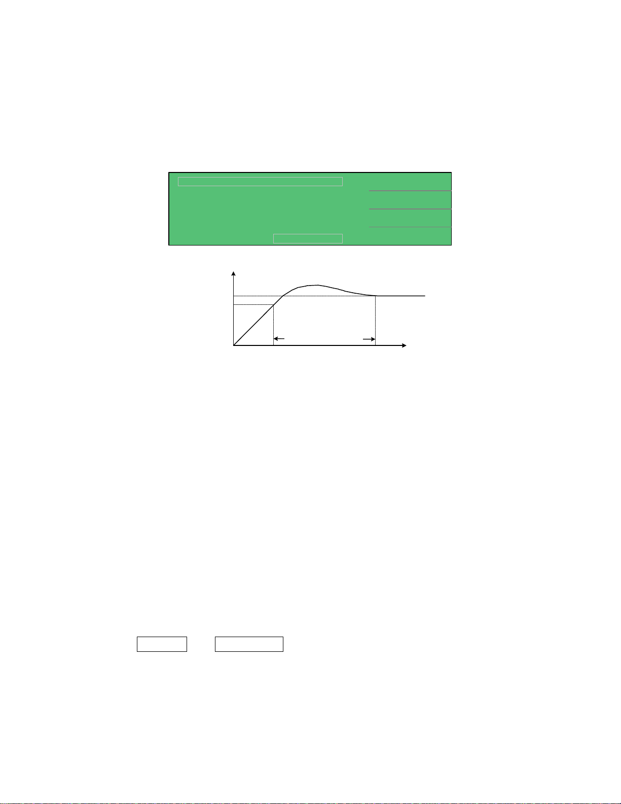
2.4.4 Withstand Voltage Test
To access the Withstand Voltage Test, press [MAIN INDEX] and [F4] = NEXT PAGE 1/2 and
then press [F1] = W.V. TEST. The MEAS DISPLAY menu will appear. Program the Test
Voltage, Constant Current, Measurement Time and maximum Charge Time. Refer to paragraphs
2.5.8 through 2.5.10 for programming details.
< MEAS DISPLAY: W.V. TEST >
Vf
:
50.0V
Tr :
Vt : V
Vm = 0.0V
Vt
Vf
0
0.15
58.00
(V)
S
58.0V/30.15S
DISCHARGECHARGE TEST
Withs tand Voltage Time
C.C.
Tend
CHG Tend
TendTr0
:
:
(t)
2.0mA
30S
5S:
Figure 2-7: Withstand Voltage Parameters
Withstand Voltage is the voltage at which the product’s insulation begins to break down. There
are however many definitions for Withstand Voltage. The 1855 instrument and this manual use
the WV terminology from the EIAJ RC-2364A standard, “Test Methods of Electrode Foils for
Aluminum Electrolytic Capacitors”.
Vf: The standard dielectric withstand voltage
CC: The constant charge current for the WV test
Tend: The measurement time for the WV test. Tend = Tr+ the programmed test time.
CHG. Tend: The maximum charge time for the WV test.
Tr: The time between the start of the current application and the voltage reaching
90% of rated withstand voltage (Vf).
Vt: The measured voltage at the end of the WV test.
Figure 2-7 illustrates a Withstand Voltage test. The following parameters were set: Vf=50V,
CC=2mA, Tend=30seconds and CHG Tend=5seconds. After [TRIGGER] is pressed, the results
shown in Figure 2-7 are Rise Time (Tr) = 0.15seconds and Measured Voltage (Vt) = 58.00V. In
the bottom left-hand corner above the test status boxes (CHARGE – TEST – DISCHARGE) are
two results: Vm=0.0V and 58.0V/30.15S. The Vm=0.0V box is the monitor of the output
voltage during the test. The 58.0V/30.15S box is the last measured voltage and time when the
test ended.
Page 38 of 76 Interface
Page 39

2.4.5 Compare
The Compare function provides the capability to set an upper and/or lower limit for a leakage
current or insulation resistance test and to display Pass/Fail with the measured result. To access
the Compare function, press [MAIN INDEX] and [F4] = NEXT PAGE 1/2 then press [F2] =
COMPARE. Select the Parameter (L.C. or IR) and program the Upper and Lower limits.
The Upper Limit is the high limit or upper value for a test to be considered a pass. If the
measured value is higher than the upper limit the test is considered a fail. The Lower Limit is
the lower value for a test to be considered a pass. If the measured value is lower than the low
limit the test is considered a fail.
In an LC test, the range for Upper Limit is 0.000uA – 999.999mA and the Lower Limit range is
0.000uA to the Upper Limit. In an IR test, the range of the Upper Limit is 0.01kΩ – 99.99GΩ
and the Lower Limit is 0.01kΩ – the Upper Limit.
< MAIN INDEX >
SEQ. TEST
STEP TEST
NULL
NEXT PAGE 1/2
< MAIN INDEX >
< MEAS INDEX: COMPARE >
:
L.C.
UPPER (+)
LOWER (-)::
< MEAS INDEX: COMPARE >
UPPER (+)
LOWER (-)::
000.000mA
- - - - - -
:L.C.
0.000mA
02
- - - - - -
W.V. TEST
COMPARE
NEXT PAGE 2/2
COMPARE : ONPARAMETER
EXIT
DIGIT UP
DIGIT DOWNPARAMETER
DIGIT
LIMIT OFF
Select
F2
Compare
Function
Turn
Compare
F2
ON
F1
Increase value of underscored digit
F2
Decrease value of underscored digit
F3
Move underscore cursor to next digit
F4
Turn Upper or Lower Limit Off
Figure 2-8: Compare Function
Interface Page 39 of 76
Page 40

To set up and display PASS/FAIL on the MEAS DISPLAY screen, use the COMPARE function.
Example: Parameter = Leakage Current. Upper Limit = 15mA, Lower Limit = 0.
< MAIN INDEX >
SEQ. TEST
STEP TEST
NULL
NEXT PAGE 1/2
Select:
Upper (+)
Select:
Lower (-)
PRESS
MEAS
DISPLAY
< MAIN INDEX >
< MEAS INDEX: COMPARE >
L.C.
:
UPPER (+)
LOWER (-)::
000.000mA
- - - - - -
< MEAS INDEX: COMPARE >
:L.C.
UPPER (+)
LOWER (-)::
0.000mA
02
- - - - - -
< MEAS INDEX: COMPARE >
:L.C.
UPPER (+)
LOWER (-)::
015.000mA
- - - - - -
< MEAS DISPLAY: STEP TEST >
W.V. TEST
COMPARE
NEXT PAGE 2/2
COMPARE : ONPARAMETER
EXIT
DIGIT UP
DIGIT DOWNPARAMETER
DIGIT
LIMIT OFF
DIGIT UP
DIGIT DOWNPARAMETER
DIGIT
LIMIT OFF
TEST V.
:
20V
Select
F2
Compare
Function
Turn
Compare
F2
ON
F1
Increase value of underscored digit
F2
Decrease value of underscored digit
F3
Move underscore cursor to next digit
F4
F1
F2
F3
F4
Turn Lower Limit Off
:
A
:
:
:
:
A
0.5mA
20mA
20V
0.5mA
2uA
PRESS
TRIGGER
Lc :
Vm = 0.0V
DISCHARGECHARGE TEST
< MEAS DISPLAY: STEP TEST >
Lc :
0.750
PASS
Vm = 20.0 V
DISCHARGECHARGE TEST
mA
A
C.C.
RANGE
NEXT PAGE 1/2
TEST V.
C.C.
RANGE
NEXT PAGE 1/2
Figure 2-9: Compare Example
Page 40 of 76 Interface
Page 41

2.5 MEAS DISPLAY
The 1855 instrument’s stand-by display is the MEAS DISPLAY. After power has been applied
to the instrument and it cycles quickly through the information screen, the instrument reverts to
the MAIN INDEX. Once [SEQ. TEST] or [STEP TEST] is selected the instrument enters the
MEAS DISPLAY. To view the instrument information screen as illustrated in Figure 2.10,
press [SYSTEM SETUP] then [⇐].
QUADTECH 1855
LEAKAGE CURRENT/IR METER
Copyright (c) AUGUST 2003
VERSION 1.02 BETA .09.02 CPLD:1855
TEL 1-800-253-1230 FAX 1-978-461-4295
Figure 2.10: Instrument Information Screen
< MEAS DISPLAY: SEQ. TEST >
TEST V.
1.0V
:
Lc :
Vm = 0.0V
DISCHARGECHARGE TEST
< MEAS DISPLAY: SEQ. TEST >
Lc :
Vm = 0.0V
DISCHARGECHARGE TEST
A
A
C.C.
RANGE
NEXT PAGE 1/2
CHG T.
DWELL T
SPEED
NEXT PAGE 2/2
0.5mA
:
2uA
A
:
:
0.2 S
:
MEDIUM
:
0 S
Figure 2.11: MEAS DISPLAY- SEQUENCE TEST
< MEAS DISPLAY: STEP TEST >
Lc :
Vm = 0.0V
DISCHARGECHARGE TEST
< MEAS DISPLAY: STEP TEST >
Lc :
TEST V.
A
A
C.C.
RANGE
NEXT PAGE 1/2
TRIGGER
SPEED::
1.0V
:
0.5mA
:
2uA
:
A
INT
MEDIUM
Vm = 0.0V
DISCHARGECHARGE TEST
NEXT PAGE 2/2
Figure 2-12: MEAS DISPLAY – STEP TEST
Interface Page 41 of 76
Page 42

Figure 2.11 illustrates the two pages of parameters that can be programmed within the MEAS
DISPLAY for a SEQUENCE TEST. Figure 2.12 illustrates the two pages of parameters that can
be programmed within the MEAS DISPLAY for a STEP TEST. The two tests have the similar
programmable parameters with the exception of Charge Time, Range Dwell and Trigger. All
programmable parameters are explained in Paragraphs 2.5.1 through 2.5.8.
2.5.1 Test Voltage
The test voltage can be programmed from 1.00V to 650V. In MEAS DISPLAY press [F1] =
TEST V so that the 1.00 V box is highlighted. Use the up arrow or down arrow keys to
in/decrease the voltage in multi-V increments. The left and right arrows will increase/decrease
the voltage in 1V increments. The instrument default setting is 1.00V.
UP arrow [⇑] key: 6.3 → 10.0 → 16.0 → 25.0 → 35.0 → 50.0 → 63.0 → 100.0 → 160.0 →
200.0 → 250.0 → 350.0 → 400.0 → 450.0 → 500.0 → 550.0 → 600.0 → 630.0.
DOWN arrow [⇓] key: 630.0 → 600.0 → 550.0 → 500.0 → 450.0 → 400.0 → 350.0 → 250.0
→ 200.0 → 160.0 → 100.0 → 63.0 → 50.0 → 35.0 → 25.0 → 16.0 → 10.0 → 6.3.
RIGHT arrow [⇒] key: increase voltage in 1V increments.
LEFT arrow [⇐] key: decrease voltage in 1V increments.
F1
< MEAS DISPLAY: SEQ. TEST >
TEST V.
1.0
:
V
Select Test V
Lc :
Vm = 0.0V
A
DISCHARGECHARGE TEST
C.C.
RANGE
NEXT PAGE 1/2
:
:
0.5mA
2uA
1.0, 6.3 - 630V
630V - 6.3V
630V - 650V
6.3 - 1.0V
2.5.2 Constant Charge Current
The test current can be programmed from 0.5mA to 500mA. In MEAS DISPLAY press [F2] =
C.C so that the 0.5 mA box is highlighted. Use the up arrow [⇑] key to increase the current or
use the down arrow [⇓] key to decrease the current in 5/50mA increments. The left and right
arrows will increase/decrease the current in 1mA increments. The instrument default setting is
0.5mA.
< MEAS DISPLAY: SEQ. TEST >
Lc :
Vm = 0.0V
DISCHARGECHARGE TEST
A
TEST V.
C.C.
RANGE
NEXT PAGE 1/2
:
:
:
1.0 V
0.5 mA
2uA
F2
0.5 - 450.5mA
450.5 - 0.5mA
450.5 - 500.0mA
500.0mA - 450.5
NOTE:
For the WV test, the range of C.C. is from 0.5mA to 150mA.
Page 42 of 76 Interface
Page 43

UP arrow [⇑] key: increase current by 5mA from 0.5mA to 100mA then by 50mA from 100mA
to 500mA
DOWN arrow [⇓] key: decrease current by 50mA from 500mA to 100mA then by 5mA from
100mA to 0.5mA
RIGHT arrow [⇒] key: increase current in 1mA increments.
LEFT arrow [⇐] key: decrease current in 1mA increments.
2.5.3 Range
The 1855 instrument’s measurement range can be selected as AUTO or HOLD. The instrument
current measurement ranges are 20mA, 2mA, 200uA, 20uA and 2uA. In MEAS DISPLAY, press
[F3] = RANGE so that the A box is highlighted*. The instrument default setting is A (Auto
Range).
* Use the up arrow [⇑] key to toggle between A (Auto) and H (Hold).
V
< MEAS DISPLAY: SEQ. TEST >
TEST V.
1.0
:
Lc :
Vm = 0.0V
DISCHARGECHARGE TEST
< MEAS DISPLAY: SEQ. TEST >
Lc :
Vm = 0.0V
DISCHARGECHARGE TEST
A
A
C.C.
RANGE
NEXT PAGE 1/2
TEST V.
C.C.
RANGE
NEXT PAGE 1/2
:
:
:
:
:
0.5mA
A
1.0
0.5mA
2uA
2uAA
Toggle between:
F3
A = Auto
H = Hold
V
2uA - 20uA - 200uA - 2mA - 20mA
20mA - 2mA - 200uA - 20uA - 2uA
Press [F3] = RANGE a second time to select the value of the range.
UP arrow [⇑] key: increase range: 2uA → 20uA → 200uA → 2mA → 20mA
DOWN arrow [⇓] key: decrease range: 20mA → 2mA → 200uA → 20uA → 2uA
Interface Page 43 of 76
Page 44

2.5.4 Charge Time
The charge time can be programmed from 0 to 999seconds. In MEAS DISPLAY press [F4] =
NEXT PAGE 1/2. Press [F1] = CHG T so that the 0 s box is highlighted. Use the up or down
arrow keys to in/decrease the charge time by base-10 second increments. The left and right
arrows will increase/decrease the time in 1second increments. The instrument default setting is
0s.
< MEAS DISPLAY: SEQ. TEST >
CHG T.
0
:
F1
s
Lc :
Vm = 0.0V
A
DISCHARGECHARGE TEST
DWELL T
SPEED
NEXT PAGE 2/2
:
0.2 S
:
MEDIUM
0 - 900s
by base-10
900 - 999s
by base-1
UP arrow [⇑] key: 0 → 10 → 20 → 30 → 40 → 50 → 60 → 70 → 80 → 90 → 100 → 200 →
300 → 400 → 500 → 600 → 700 → 800 → 900.
RIGHT arrow [⇒] key: increase charge time in 1 second increments. (example: 900 to 999)
DOWN arrow [⇓] key: 999 → 899 → 799 → 699 → 599 → 499 → 399 → 299 → 199 → 99 →
89 → 79 → 69 → 59 → 49 → 39 → 29 → 19 → 9.
LEFT arrow [⇐] key: decrease charge time in 1 second increments. (example: 9 to 0)
2.5.5 Dwell Time
The dwell time can be programmed from 0.2 to 999seconds. In MEAS DISPLAY press [F4] =
NEXT PAGE 1/2. Press [F2] = DWELL T so that the 0.2 s box is highlighted. Use the up or
down arrow keys to in/decrease the dwell time by base-10 second increments. The left and right
arrows will increase/decrease the time in 1second increments. The instrument default setting is
0s.
< MEAS DISPLAY: SEQ. TEST >
Lc :
Vm = 0.0V
DISCHARGECHARGE TEST
CHG T.
A
DWELL T
SPEED
NEXT PAGE 2/2
0
:
:
0.2
:
MEDIUM
s
F2
s
0.2 - 900s
by base-10
900 - 999s
by base-1
UP arrow [⇑] key: 0.2 → 10 → 20 → 30 → 40 → 50 → 60 → 70 → 80 → 90 → 100 → 200 →
300 → 400 → 500 → 600 → 700 → 800 → 900.
RIGHT arrow [⇒] key: increase dwell time in 1 second increments. (example: 900 to 999)
Page 44 of 76 Interface
Page 45

DOWN arrow [⇓] key: 999 → 899 → 799 → 699 → 599 → 499 → 399 → 299 → 199 → 99 →
89 → 79 → 69 → 59 → 49 → 39 → 29 → 19 → 9.
LEFT arrow [⇐] key: decrease dwell time in 1 second increments. (example: 9 to 0)
2.5.6 Speed
Program the measurement speed of the 1855 instrument to Slow (7measurements/second),
Medium (14 measurements/second) or Fast (18 measurements/second). In MEAS DISPLAY,
press [F4] = NEXT PAGE 1/2 and then press [F3] = SPEED so that the MEDIUM box is
highlighted. Press [F3] = SPEED to toggle through and select the measurement rate: SLOW,
MEDIUM or FAST. The instrument default setting is MEDIUM (14 meas/second).
s
< MEAS DISPLAY: SEQ. TEST >
CHG T.
0
:
Lc :
Vm = 0.0V
A
DISCHARGECHARGE TEST
DWELL T
SPEED
NEXT PAGE 2/2
:
0.2
MEDIUM
:
s
F3
Toggle between:
SLOW
MEDIUM
FAST
2.5.7 Trigger
In the Step Test only, the 1855 instrument can be triggered manually, internally or externally.
In MEAS DISPLAY, press [F4] = NEXT PAGE 1/2 and then press [F1] = TRIGGER so that the
INT box is highlighted. Press [F1] = TRIGGER to change the trigger. The instrument default
setting is INT (internal trigger). When MANUAL trigger is selected, one measurement will be
made each time the trigger is pressed. When EXTERNAL trigger is selected, one measurement
will be made each time the external trigger is asserted by the handler. When INTERNAL trigger
is selected, measurements are performed continuously when in [MEAS DISPLAY].
Toggle
< MEAS DISPLAY: STEP TEST >
Lc :
Vm = 0.0V
DISCHARGECHARGE TEST
TRIGGER
A
SPEED::
NEXT PAGE 2/2
INT
MEDIUM
F1
between:
INTernal
EXTernal
MANual
Interface Page 45 of 76
Page 46

2.5.8 Rated Withstand Voltage (Vf)
In the W.V. Test only, the rated withstand voltage (Vf) can be programmed from 1.00V to
650V. In MEAS DISPLAY press [F1] = Vf so that the 1.00 V box is highlighted. Use the up
arrow or down arrow keys to in/decrease the voltage in multi-V increments. The left and right
arrows will increase/decrease the voltage in 1V increments. The instrument default setting is
1.00V.
F1
< MEAS DISPLAY: W.V. TEST >
Vf
:
50.0 V
Select Vf
Tr :
Vt : V
Vm = 0.0V
0.15
58.00
58.0V / 30.15S
DISCHARGECHARGE TEST
S
C.C
Tend :
CHG Tend
2.0 mA
:
Tr+ 30 s
:
5 s
1.0, 6.3 - 630V
630V - 6.3V
630V - 650V
6.3 - 1.0V
UP arrow [⇑] key: 6.3 → 10.0 → 16.0 → 25.0 → 35.0 → 50.0 → 63.0 → 100.0 → 160.0 →
200.0 → 250.0 → 350.0 → 400.0 → 450.0 → 500.0 → 550.0 → 600.0 → 630.0.
DOWN arrow [⇓] key: 630.0 → 600.0 → 550.0 → 500.0 → 450.0 → 400.0 → 350.0 → 250.0
→ 200.0 → 160.0 → 100.0 → 63.0 → 50.0 → 35.0 → 25.0 → 16.0 → 10.0 → 6.3.
RIGHT arrow [⇒] key: increase voltage in 1V increments.
LEFT arrow [⇐] key: decrease voltage in 1V increments.
2.5.9 Measurement Time (Tend)
In the W.V. Test only, the measurement time can be programmed from 30 to 600seconds. In
MEAS DISPLAY press [F3] = Tend so that the 30 s box is highlighted. Use the up or down
arrow keys to in/decrease the measure time by 10 second increments. The left and right arrows
will increase/decrease the time in 1second increments. The instrument default setting is 30s.
< MEAS DISPLAY: W.V. TEST >
Vf
:
50.0 V
Tr :
Vt : V
Vm = 0.0V
0.15
58.00
58.0V / 30.15S
DISCHARGECHARGE TEST
S
C.C
Tend :
CHG Tend
2.0 mA
:
30
Tr+ s
:
5 s
F3
Select Tend
30 - 530s
by base-10
530 - 600s
by base-1
UP arrow [⇑] key: 30 → 40 → 50 → 60 → 70 → 80 → 90 → 100 → 200 → 300 → 400 → 500
→ 600.
RIGHT arrow [⇒] key: increase measurement time in 1 second increments.
DOWN arrow [⇓] key: 600 → 500 → 400 → 300 → 200 → 100 → 90 → 80 → 70 → 60 → 50
→ 40 → 30.
LEFT arrow [⇐] key: decrease measurement time in 1 second increments.
Page 46 of 76 Interface
Page 47

2.5.10 Maximum Charge Time (CHG Tend)
In the W.V. Test only, the charge time can be programmed from 5 to 600seconds. In MEAS
DISPLAY press [F4] = CHG Tend so that the 5 s box is highlighted. Use the up or down arrow
keys to in/decrease the charge time by 10 second increments. The left and right arrows will
increase/decrease the time in 5 second increments. The instrument default setting is 5s.
< MEAS DISPLAY: W.V. TEST >
Vf
:
50.0 V
Tr :
Vt : V
Vm = 0.0V
0.15
58.00
58.0V / 30.15S
DISCHARGECHARGE TEST
S
C.C
Tend :
CHG Tend
2.0 mA
:
Tr+ 30 s
:
5s
F4
5 - 505s
Select CHG Tend
by base-10
505 - 600s
by base-1
UP arrow [⇑] key: 5 → 15 → 25 → 35 → 45 → 55 → 65 → 75 → 85 → 95 → 105 → 205 →
305 → 405 → 505.
RIGHT arrow [⇒] key: increase charge time in 1 second increments. (example: 505 to 600)
DOWN arrow [⇓] key: 600 → 500 → 400 → 300 → 200 → 100 → 90 → 80 → 70 → 60 → 50
→ 40 → 30 → 20 → 10.
LEFT arrow [⇐] key: decrease charge time in 1 second increments. (example: 10 to 5)
Interface Page 47 of 76
Page 48

2.6 Connection to Device under Test
Figure 2-13 illustrates the connection of the 1855 instrument to a DUT using the 1855-01 Lead
Set. For Leakage Current, Insulation Resistance and Withstand Voltage Tests, the red alligator
clip/BNC cable is connected between the silver INPUT terminal on the 1855 unit and the high
side of the device under test. The black alligator clip/banana cable is connected between the
white HV (-) terminal on the 1855 unit and the low side of the DUT.
QuadTech
<MEAS. DISPLAY: SEQ. TEST>
LC :
CHARGE TEST DISCHARGE
01
l
1855 Capacitor Leakage Current /IR Meter
1.5 mA
TEST V
C.C
RANGE
NEXT PAGE 1/2
+
1.0
:
0.5
:
2
:
A
HV
-
MEAS
MAIN
V
F1
mA
F2
F3
uA
F4
(-)(+)INPUT
F1
F2
F3
F4
DISPLAY
CHARGE/TEST DISCHARGE
INDEX
TRIGGER
SYSTEM
SETUP
DUT
Figure 2-13: Connection for Leakage Current Test
Page 48 of 76 Interface
Page 49

2.7 Measurement Procedure
Before a measurement is made verify the following:
1. 1855 instrument [POWER] ON.
2. 15-minute warm-up.
3. Test parameters programmed and shown on MEAS DISPLAY.
4. Test cables or fixture connected.
5. NULL function initiated.
6. Device under test connected.
To initiate a test:
• Press [TRIGGER].
• The test voltage is shut off when all test steps are completed,
• OR when a test result is judged a FAIL per programmed test limits.
• The test result is displayed on MEAS DISPLAY
NOTE:
If for any reason the output must be terminated during a test, press the right arrow marked
“DISCHARGE”.
The 1855 instrument judges the measurement value based on the COMPARE function set up
previously. Refer to paragraph 2.4.5 for instructions on setting the COMPARE Pass/Fail
judgment parameter. Upon completion of the test the output voltage is terminated and the display
shows the test result.
CAUTION:
Before touching the DUT or the 1855 instrument, make sure all capacitive devices have been
fully discharged.
Interface Page 49 of 76
Page 50

Page 51
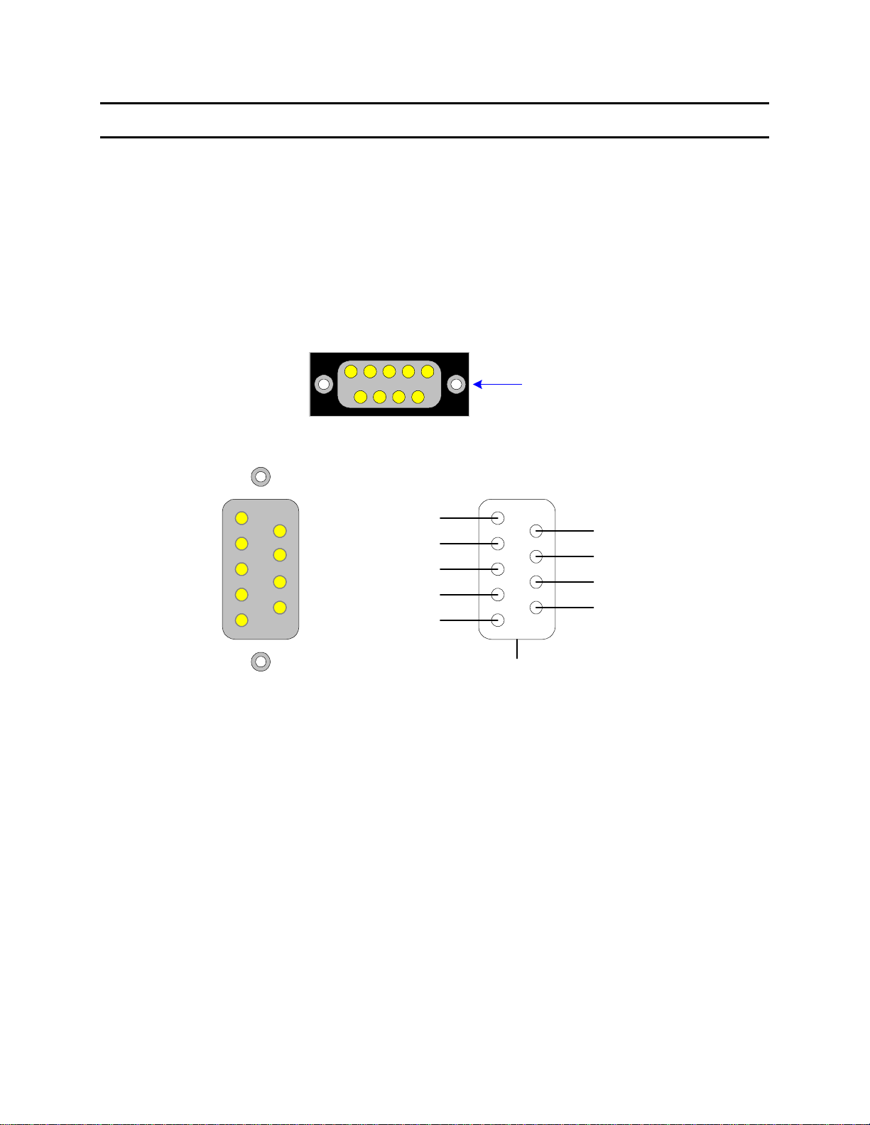
Section 3: Interface
3.1 RS-232 Interface
3.1.1 RS-232 Pin Configuration
The 1855 instrument comes standard with an RS232 Interface for remote operation. Connection
is through the black/silver 9-pin connector labeled ‘RS232’ on the rear panel of the 1855
instrument. Figure 3-1 illustrates the designation of the pins on the RS232 connector. The
connection cable must be a ‘straight through’ cable for the 1855 unit to communicate.
RS232
1
Figure 1-3
DB9 Female
1
6
2
7
3
8
4
9
5
Data Carrier Detected
Signal Ground
Transmitted Data
Data Terminal Ready
Received Data
1
2
3
4
5
Shield
Data Set Ready
6
Request to Send
7
8
Clear to Send
9
Ring Indicator
Figure 3-1: RS-232 Interface Pin Configuration
3.1.2 RS232 Specifications
Data Bits: 8
Stop Bits: 1
Parity: None
Baud Rate: 600, 1200, 4800, 9600, 19200 or 28800bps, Software selectable
EOS: CR + LF
Echo: Off
Interface Page 51 of 76
Page 52

Refer to paragraph 2.3.3.10. Setting the Baud Rate is done in the SYSTEM CONFIGURATION
function under SYSTEM SETUP settings:
• From the MEAS DISPLAY, press [SYSTEM SETUP]
• Press [F3] = SYSTEM CONFIG.
• Press [⇓] = until the box next to BAUD RATE is highlighted.
• Press [F1] = INCREASE or [F2] = DECREASE to select baud rate.
• Press [F4] to EXIT
3.1.3 RS232 Commands
The command set for the RS232 interface is the same as the IEEE-488 interface command set
listed in paragraphs 3.2.3 through 3.2.5 of this instruction manual.
NOTE
CR + LF is the necessary end code for the RS232 commands.
Page 52 of 76 Interface
Page 53
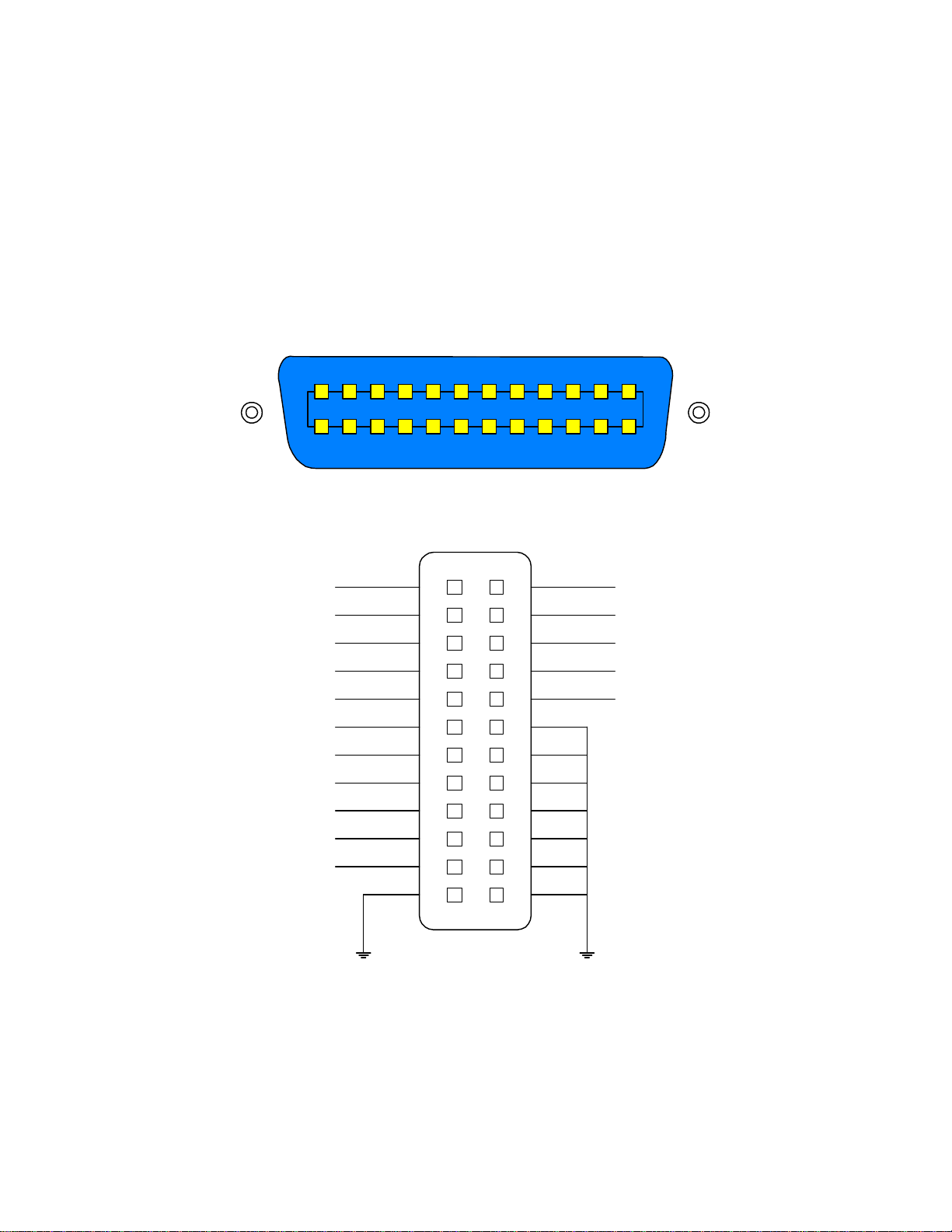
3.2 IEEE-488 Interface
3.2.1 Pin Configuration
The 1855 instrument has an optional IEEE-488 interface as illustrated in Figure 3-2. Connection
is through the blue 24-pin connector labeled ‘IEEE-488 INTERFACE’ on the rear panel of the
1855 instrument. This interface can be used to connect a system containing a number of
instruments and a controller in which each meets IEEE Standard 488.2 (Standard Digital
Interface for Programmable Instrumentation).
1855 IEEE-488 Interface PIN Configuration: Rear Panel View
12 67891011
15 1419 18 17 162024 23 2122
1855 IEEE-488 Interface PIN Designation
DIO1
DIO2
DIO3
DIO4
EOI
DAV
NFRD
NDAC
IFC
SRQ
ATN
SHIELD GND
1
2
3
4
5
6
7
8
9
10
11
12
13
14
15
16
17
18
19
20
21
22
23
24
12534
13
DIO5
DIO6
DIO7
DIO8
REN
Figure 3-2: IEEE-488 Interface Pin Configuration
Interface Page 53 of 76
Page 54

Table 3-1 lists the IEEE-488 Interface pin designations by pin number, signal name and pin
function. Bus and driver information is also listed.
Table 3-1: IEEE-488 Interface Pin Designations
Bus Driver Signal
Name
Handshake
3 States DAV 6 Low State: “Data is Available” and valid on DI01
Pin
Number
Function
through DI08
Open
Collector
Open
Collector
Control
3 States ATN 11 “Attention” specifies 1 of 2 uses for the DI01 through
NRFD 7 Low State: At least one Listener on the bus is “Not
Ready For Data”
NDAC 8 Low State: At least one Listener on the bus is “Not
Accepting Data”
DI08 lines:
Low State: Controller command messages
High State: Data bytes from the Talker device
3 States IFC 9 “Interface Clear”
Low State: Returns portion of interface system to a
known quiescent state
Open
Collector
SRQ 10 “Service Request”
Low State: A Talker or Listener signals (to the
controller) need for attention in the midst of the
current sequence of events.
3 States REN 17 “Remote Enable”
Low State: Enables each device to enter remote mode
when addressed to listen.
High State: All devices revert to Local control.
3 States EOI 5 “End of Identify”
If ATN is in HIGH state, then EOI LOW state
indicates the end of a multiple-byte data transfer
sequence.
If ATN is in LOW state, then EOI LOW state
indicates a parallel poll.
Data
Open
Collector
DI01 1
DI02 2
DI03 3
DI04 4
DI05 13
DI06 14
DI07 15
DI08 16
The 8-Line Data Bus.
If ATN is in LOW state, then the bus conveys
interface messages.
If ATN is in HIGH state, then the bus conveys device-
dependent messages. (Example: carries remote
control commands from the controller or from a talker
device)
Page 54 of 76 Interface
Page 55

3.2.2 IEEE-488 Interface Function Codes and Messages
The IEEE-488 (GPIB) address is defined under the SYSTEM SETUP in the SYSTEM CONFIG
menu. Press [SYSTEM SETUP], then the numerical key [F3] to enter the SYSTEM CONFIG
menu. Press down arrow [⇓] to enter the GPIB ADDRESS code. To select a new IEEE-488
address, use the function keys. Refer to paragraph 2.3.2 for more information. The default setting
for the IEEE address is 17.
Table 3-2 defines the IEEE-488 interface codes and their function. Table 3-3 defines the IEEE488 interface messages the 1855 instrument responds to and their function.
Table 3-2: IEEE-488 Interface Functions
Code Function
SH1 Source Handshake (Talker)
AH1 Acceptor Handshake (Listener)
T6
Basic Talker Function
Serial Poll Function
Listener-specified Talker Release Function
No TALK-ONLY Function
Basic Listener Function L4
Talker-specified Listener Release Function
SR1 Service Request Function
RL1 All Remote/Local Functions
PP0 No Parallel Poll Function
DC1 Device Clear Function
DT1 Device Trigger Function
C0 No Controller Functions
Table 3-3: IEEE-488 Interface Messages
Interface
Function Description
Message
GTL Go To Local Only addressed devices that receive this command are set to
local mode.
Cancels the remote control mode, making the front panel
switches operative.
Interface Page 55 of 76
Page 56

Table 3-4 lists the IEEE-488 interface commands the 1855 instrument accepts to set or query a
parameter value. Paragraphs 3.2.3 through 3.2.5 detail the function, format, return value and
description of the IEEE-488 commands.
Table 3-4: IEEE-488 Commands
Command Name Function Output Format
*CLS Clear Status Clear standard event status
register. Clear status bit group
register except for bit 4 (MAV)
*ESE Event Status Enable Enable standard event status
0 – 255
register value.
*ESE? Event Status Enable Query standard event status of
0 – 255
device enable register
*ESR? Event Status Register Query standard event register
0 – 255
value of device. After this
command, the standard register is
cleared to 0.
*IDN? Identification Query/Read basic device data.
(A comma separates the
identification fields.)
4 ID:
Manufacturer,
Device Model,
Serial Number,
Firmware Version
*OPC Operation Complete Operation is complete. 0
*OPC? Operation Complete Query operation complete. 1
*RST Reset Reset Device.
*SRE Service Request Enable Enable service request register
0 – 255
value.
*SRE? Service Request Enable Query/Read service request
0 – 255
register value.
*TRG Trigger Bus Trigger the 1730 instrument
*TST? Self Test Perform self test & report error 0 = no error
1 = RAM
2 = EEPROM
4 = CPLD
8 = Calibration Data
*LRN? Null Perform Null
*SAV Save Save current status to memory. 1 – 50
*RCL Recall Recall saved status from memory. 1 – 50
Page 56 of 76 Interface
Page 57
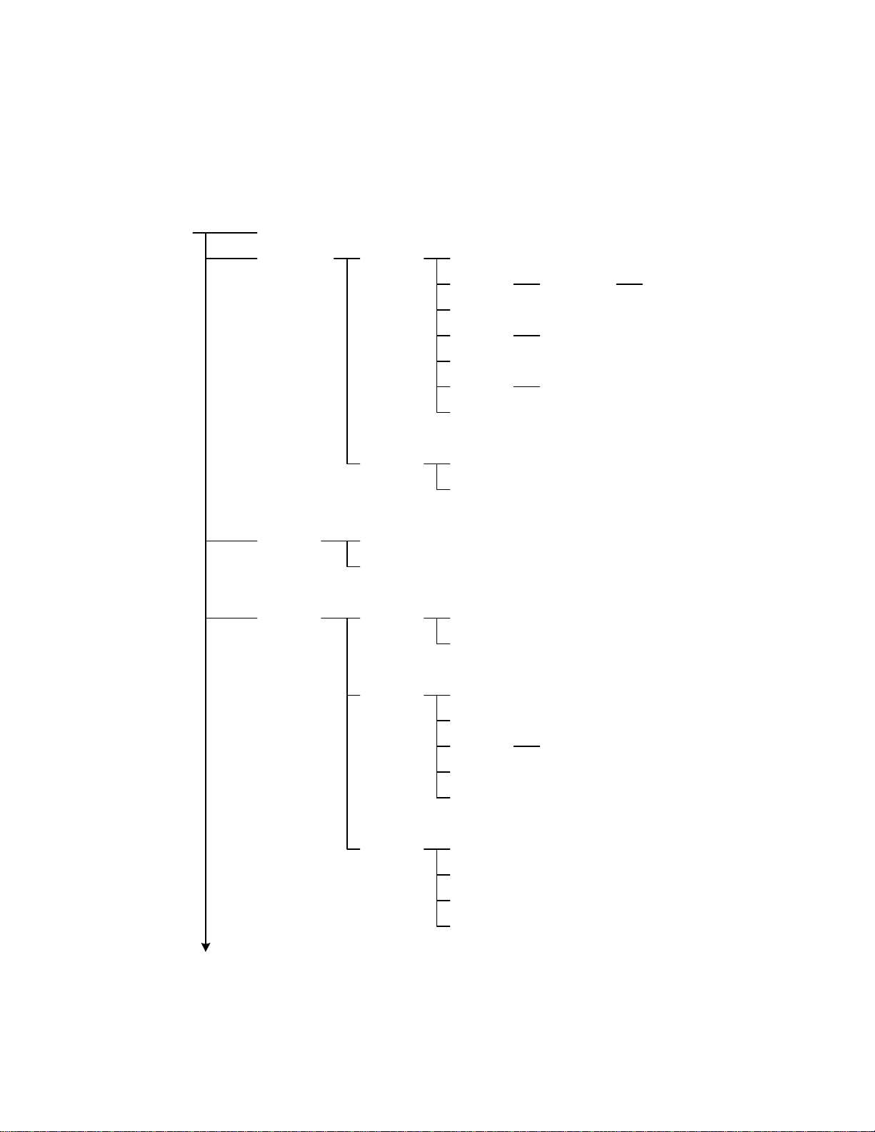
3.2.3 IEEE-488 Commands
Figure 3-3 illustrates the programming commands accepted by the IEEE-488 interface of the
1855 instrument. The commands are written in tabular format as a single reference to view all
the commands. The command format and examples are detailed in paragraphs 3.2.4 – 3.2.5.
ABORt
CALCulate LIMit FORMat
DISPlay
LCTest
BEEPer CONDition
FAIL?
LOWer
STATe
UPPer
ONOFf
NULL
STATe
WVTest
SOURce
CONFigure FUNCtion
IMMediate
DATA?
VOLTage
CURRent
STATe
DATA
DATA
SPEed
RANGe AUTO
CHG Ti me
DWELl
MEASure STATe?
IR?
LC?
VMON?
Figure 3-3a: IEEE-488 Commands
Interface Page 57 of 76
Page 58

Tabular Format IEEE-488 Commands – continued
ABORt
WVTest
TRIGger
SYSTem BEEPer
SOURce VOLTage
CONFigure
MEASure STATe?
IMMediate
SOURce
DELay
EDGE
CURRent
TEND
CHGTEND
VTerminate?
TEnd?
IMMediate
STATe
ALARm
LFRequency
HANDler
CONTrast
RANGEDwell
AVErage
PRESet
ERRor?
Figure 3-3b: IEEE-488 Commands
Page 58 of 76 Interface
Page 59

3.2.4 IEEE-488 Command Format
The IEEE-488 commands are configured in Root format. There are six levels of the instruction
from top to bottom. Follow the specific path (as illustrated in Figure 3.3) to configure a specific
command. The colon at the beginning of each line denotes that all line signals are root. Use a
colon (:) to separate levels. Use the semicolon (;) to separate two commands on the same line.
For example, to format the command for the LC function, use this path:
:CALCulate:LIMit:FORMat:LC
If the command is a setting, then put the parameter after the instruction. If the command is an
inquiry, then put a question mark (?) after the instruction.
For example, to set the beeper to sound on Fail:
:CALCulate:LIMit:BEEPer:CONDition:FAIL
To inquire what the beeper is set to:
:CALCulate:LIMit:BEEPer:CONDition?
The Ending Code can be any type in Table 3-5.
Table 3-5: IEEE-488 Interface Ending Codes
Ending Code
[CR] (0Dh)
[LF] (0Ah)
[CR] (0Dh) + [LF] (0Ah)
Interface Page 59 of 76
Page 60

3.2.5 IEEE-488 Commands - Detailed
The IEEE commands listed in Figure 3-3 are detailed in paragraphs 3.2.5.1 – 3.2.5.39 including
command, parameter, return value, function, and description. Note: Numerical data is
transferred via one of three methods: integer format, fixed decimal format or floating point
decimal format. Refer to Figure 3-4.
Integer Format
<NR1>
+
-
Example : 9000
<digit>
Fixed De cima l Format
Floating Point Format
<NR2>
+
-
<NR3>
+
-
<digit>
<digit>
Example : 9000.0
.
.
<digit>
<digit>
Example : 9.0E+3
+
E
-
Figure 3-4: Numerical Data Transfer
3.2.5.1 ABOR
Instruction: ABOR
Parameter: None
Return Value: None
Function: Terminate Trigger in process and initiates Discharge.
3.2.5.2 CALC:LIM:FORM
Instruction: CALC:LIM:FORM
Parameter: {IR⏐LC}
Return Value: {IR⏐LC}
Function: Set or Query the measurement parameter for the Compare function.
Description: IR Insulation Resistance
LC Leakage Current
3.2.5.3 CALC:LIM:BEEP:COND
Instruction: CALC:LIM:BEEP:COND
Parameter: {FAIL⏐PASS}
Return Value: {FAIL⏐PASS}
Function: Set or Query the condition on which the beeper sounds.
Description: FAIL Beeper sounds on FAIL result
PASS Beeper sounds on PASS result
<digit>
Page 60 of 76 Interface
Page 61

3.2.5.4 CALC:LIM:BEEP:STAT
Instruction: CALC:LIM:BEEP:STAT
Parameter: {OFF⏐ON⏐0⏐1}
Return Value: {0⏐1}
Function: Set or query the status of the beeper.
Description: OFF (0) Beeper sound is set to OFF
ON (1) Beeper sound is set to ON
3.2.5.5 CALC:LIM:FAIL?
Instruction: CALC:LIM:FAIL?
Parameter: {0 (FAIL)⏐1 (PASS)}
Return Value: {0⏐1}
Function: Query the result of the Compare function.
Description: 0 FAIL result
1 PASSL result
3.2.5.6 CALC:LIM:LOW[:DATA]
Instruction: CALC:LIM:LOW[:DATA]
Parameter: {The lower limit value⏐MAX⏐MIN}
Return Value: The lower limit value, the format is <NR3> (Floating point)
Function: Set or query the lower limit value.
Description: MINimum 000.000kΩ
MAXimum 9.999E14
3.2.5.7 CALC:LIM:STAT
Instruction: CALC:LIM:STAT
Parameter: {OFF⏐ON⏐0⏐1}
Return Value: {0⏐1}
Function: Set or query the state of the Compare Function.
Description: 0 Compare Function is OFF
1 Compare Function is ON
3.2.5.8 CALC:LIM:UPP[:DATA]
Instruction: CALC:LIM:UPP[:DATA]
Parameter: {The upper limit value⏐MAX⏐MIN}
Return Value: The upper limit value, the format is <NR3> (Floating point)
Function: Set or query the upper limit value.
Description: MINimum 000.001kΩ
MAXimum 9.999E14
Interface Page 61 of 76
Page 62

3.2.5.9 CALC:LIM:ONOF
Instruction: CALC:LIM:ONOF
Parameter: {0⏐1⏐2⏐3}
Return Value: {0⏐1⏐23⏐3}
Function: Set or query the status of the Compare function.
Description: 0 Compare function is OFF
1 Compare Upper Limit is ON
2 Compare Lower Limit is ON
3 Compare Upper and Lower Limits are ON
3.2.5.10 CALC:NULL:[IMM]
Instruction: CALC:NULL:[IMM]
Parameter: None
Return Value: None
Function: Initiate NULL.
Description: No data. Instrument performs Null function
3.2.5.11 CALC:NULL:DATA?
Instruction: CALC:NULL:DATA?
Parameter: None
Return Value: The Null value in <NR3> format (-20.0E6 to 20.0E6)
Function: Query the Null leakage current reading for each current range.
Description: ____ Null value of 20mA range
____ Null value of 2mA range
____ Null value of 200uA range
____ Null value of 20uA range
____ Null value of 2uA range
3.2.5.12 DISP:STAT?
Instruction: DISP:STAT?
Parameter: {ON (1)⏐OFF (0)}
Return Value: {LCTEST⏐WVTEST⏐NULL ⏐MAIN ⏐SYSTEM}
Function: Query the status of the LCD display.
Description: LCTEST Display is in LCTEST mode
WVTEST Display is in WVTEST mode
NULL Display is in NULL mode
MAIN Display is in MAIN mode
SYSTEM Display is in SYSTEM mode
Page 62 of 76 Interface
Page 63

3.2.5.13 DISP:⏐ WVT, L CT, null, main, system⏐
Instruction: DISP: WVT
DISP: LCT
DISP: NULL
DISP: MAIN
DISP: SYSTem
Parameter: None
Return Value: None
Function: Set the Display to WV Mode, L CT mode, null, main or system mode.
Description: Set the Display to WV Mode
3.2.5.14 LCT:SOUR:VOLT
Instruction: LCT:SOUR:VOLT
Parameter: {Test Voltage⏐MIN⏐MAX}
Unit: Volts
Return Value: {Test Voltage} in {NR3} format
Function: Set or query the test voltage for the LC Test.
{Voltage} 1.0 -650V
MIN 1.0V
MAX 650V
3.2.5.15 LCT:SOUR:CURR
Instruction: LCT:SOUR:CURR
Parameter: {Test Current⏐MIN⏐MAX}
Unit: Milliamps
Return Value: {Test Current} in {NR3} format
Function: Set or query the test current for the LC Test.
{current} 0.5mA – 500mA
MIN 0.5mA
MAX 500mA (150mA for V>100V)
3.2.5.16 LCT:CONF:FUNC
Instruction: LCT:CONF:FUNC
Parameter: {SEQ⏐STEP}
Return Value: {SEQ⏐STEP}
Function: Set or query the configuration of the LC Test.
Description: SEQ LC Test is a Sequence Test
STEP LC Test is a Single Manual Test
Interface Page 63 of 76
Page 64

3.2.5.17 LCT:CONF:SPE
Instruction: LCT:CONF:SPE
Parameter: {FAST⏐MEDIUM⏐SLOW}
Return Value: {FAST⏐MEDIUM⏐SLOW}
Function: Set or query the Measurement Speed.
Description: FAST 18 measurements/second
MEDIUM 14 measurements/second
SLOW 7 measurements/second
3.2.5.18 LCT:CONF:RANG
Instruction: LCT:CONF:RANG
Parameter: {<range>⏐MIN⏐MAX}
Return Value: {<range>}
Function: Set or query the measurement range for the LC Test.
Description: 4 20mA
3 2mA
2 200uA
1 20uA
0 2uA
MIN 2uA
MAX 20mA
3.2.5.19 LCT:CONF:RANG:AUTO
Instruction: LCT:CONF:RANG:AUTO
Parameter: {OFF⏐ON⏐0⏐1}
Return Value: {0⏐1}
Function: Set or query if the Auto Range function is OFF or ON.
Description: 0 Auto Range is OFF
1 Auto Range is ON
3.2.5.20 LCT:CONF:CHGT
Instruction: LCT:CONF:CHGT
Parameter: {<numeric value>⏐MIN⏐MAX}
Return Value: {<numeric value>}
Function: Set or query the charge time for the LC Test.
Description: <numeric value> 0 – 999seconds
MIN 0seconds
MAX 999seconds
Page 64 of 76 Interface
Page 65

3.2.5.21 LCT:CONF:DWEL
Instruction: LCT:CONF:DWEL
Parameter: {<numeric value>⏐MIN⏐MAX}
Return Value: {<numeric value>}
Function: Set or query the dwell time for the LC Test.
Description: <numeric value> 0.2 – 999seconds
MIN 0.2seconds
MAX 999seconds
3.2.5.22 LCT:MEAS:STAT?
Instruction: LCT:MEAS:STAT?
Parameter: None
Return Value: {CHG⏐TEST⏐DCHG}
Function: Query the test status of the LC Test.
Description: CHG Instrument is in Charge mode
TEST Instrument is in Test mode
DCHG Instrument is in Discharge mode
3.2.5.23 LCT:MEAS:FETC?
Instruction: LCT:MEAS:FETC?
Parameter: None
Return Value: {0⏐1}, {ON⏐PASS⏐HIGH⏐LOW}
Function: Query the test result of the LC Test.
Description: 0 Okay
1 Error
ON Instrument in Test mode
PASS Test Passed
HIGH Test Failed – result above High Limit
LOW Test Failed – result below Low Limit
3.2.5.24 LCT:MEAS:IR?
Instruction: LCT:MEAS:IR?
Parameter: None
Return Value: {Measured value} in <NR3> format
Function: Query the IR measurement value.
Description: IR measurement value
Interface Page 65 of 76
Page 66

3.2.5.25 LCT:MEAS:LC?
Instruction: LCT:MEAS:LC?
Parameter: None
Return Value: {Measured value} in <NR3> format
Function: Query the LC measurement value.
Description: LC measurement value
3.2.5.26 LCT:MEAS:VMON?
Instruction: LCT:MEAS:VMON?
Parameter: None
Return Value: {Measured value} in <NR3> format
Function: Query the value of the monitored voltage (voltage across DUT).
Description: VMON value
3.2.5.27 WVT:SOUR:VOLT
Instruction: WVT:SOUR:VOLT
Parameter: {<numeric value>⏐MIN⏐MAX}
Unit: Volts
Return Value: {Test Voltage} in <NR3> format
Function: Set or query the test voltage for the Withstand Voltage Test.
Description: <numeric value> 1.0 – 650volts
MIN 1.0volt
MAX 650volts
3.2.5.28 WVT:SOUR:CURR
Instruction: WVT:SOUR:CURR
Parameter: {<numeric value>⏐MIN⏐MAX}
Unit: Milliamps
Return Value: {Test Current} in <NR3> format
Function: Set or query the test current for the Withstand Voltage Test.
Description: <numeric value> 0.5 – 150mA
MIN 0.5mA
MAX 150mA
Page 66 of 76 Interface
Page 67

3.2.5.29 WVT:CONF:TEND
Instruction: WVT:CONF:TEND
Parameter: {<numeric value>⏐MIN⏐MAX}
Unit: seconds
Return Value: {Measurement Time} in <NR3> format
Function: Set or query the measurement time for the WV Test.
Description: <numeric value> 30 – 600seconds
MIN 30seconds
MAX 600seconds
3.2.5.30 WVT:CONF:CHGTEND
Instruction: WVT:CONF:CHGTEND
Parameter: {<numeric value>⏐MIN⏐MAX}
Unit: seconds
Return Value: {Maximum Charge Time} in <NR3> format
Function: Set or query the maximum charge time for the WV Test.
Description: <numeric value> 5 – 600seconds
MIN 5seconds
MAX 600seconds
3.2.5.31 WVT:MEAS:STAT?
Instruction: WVT:MEAS:STAT?
Parameter: None
Return Value: {CHG⏐TEST⏐DCHG}
Function: Query the test status of the WV Test.
Description: CHG Instrument is in Charge mode
TEST Instrument is in Test mode
DCHG Instrument is in Discharge mode
3.2.5.32 WVT:MEAS:VT?
Instruction: WVT:MEAS:VT?
Parameter: None
Return Value: {Test Voltage} in <NR3> format
Function: Query the Test Voltage at the Termination of the WV Test.
Description: <numeric value> 1.0 – 650volts
Interface Page 67 of 76
Page 68

3.2.5.33 WVT:MEAS:TE?
Instruction: WVT:MEAS:TE?
Parameter: None
Return Value: {Measurement Time} in <NR3> format
Function: Query the total Measurement Time of the WV Test (Tr + Test Time).
Description: <numeric value> 30 – 600seconds
3.2.5.34 TRIG[:IMM]
Instruction: TRIG[:IMM]
Parameter: None
Return Value: None
Function: Initiate the Trigger function.
3.2.5.35 TRIG:SOUR
Instruction: TRIG:SOUR
Parameter: {BUS⏐EXT⏐INT⏐MAN}
Return Value: {BUS⏐EXT⏐INT⏐MAN}
Function: Set or query the trigger mode.
Description: BUS Bus trigger
EXTernal External trigger
INTernal Internal trigger
MANual Manual trigger
3.2.5.36 TRIG:DEL
Instruction: TRIG:DEL
Parameter: {<numeric value>⏐MIN⏐MAX}
Unit: milliseconds
Return Value: {Trigger Delay Time} in <NR3> format
Function: Set or query the trigger delay time.
Description: <numeric value> 0 – 9999milliseconds
MIN 0milliseconds
MAX 9999milliseconds
3.2.5.37 TRIG:EDGE
Instruction: TRIG:EDGE
Parameter: {FALL⏐RISI}
Return Value: {FALL⏐RISI}
Function: Set or query the edge on which to initiate the trigger.
Description: FALL Measurement is triggered on falling edge
RISI Measurement is triggered on rising edge
Page 68 of 76 Interface
Page 69

3.2.5.38 SYST:BEEP[:IMM]
Instruction: SYST:BEEP[:IMM]
Parameter: None
Return Value: None
Function: Set the beeper to sound immediately.
3.2.5.39 SYST:BEEP:STAT
Instruction: SYST:BEEP:STAT
Parameter: {OFF (0)⏐ON, LOW (1)⏐ON, HIGH (2)}
Return Value: {0⏐1⏐2}
Function: Set the loudness of the beeper.
Description: 0 Turn Beeper OFF
1 Set Beeper sound to LOW
2 Set Beeper sound to HIGH
3.2.5.40 SYST:ALAR
Instruction: SYST:ALAR
Parameter: {PULS⏐CONT}
Return Value: {PULS⏐CONT}
Function: Set the mode the alarm will sound in.
Description: PULS The alarm sound will pulse
CONT The alarm will continuously sound
3.2.5.41 SYST:LFR
Instruction: SYST:LFR
Parameter: {50⏐60}
Unit: Hz
Return Value: {50⏐60}
Function: Set or query the Line Frequency.
Description: 50Hz AC Power Line Source is 50Hz
60Hz AC Power Line Source is 60Hz
3.2.5.42 SYST:HAND
Instruction: SYST:HAND
Parameter: {CLEA⏐HOLD}
Return Value: {CLEA⏐HOLD}
Function: Set the Handler to clear result or hold result for each test
Description: CLEA Handler will clear result after each test
HOLD Handler will hold result after each test
Interface Page 69 of 76
Page 70

3.2.5.43 SYST:CONT
Instruction: SYST:CONT
Parameter: {<numeric value>}
Return Value: {Contrast} in <NR1> format
Function: Set or query the contrast of the display.
Description: <numeric value> 1-16
3.2.5.44 SYST:RANGED
Instruction: SYST:RANGED
Parameter: {<numeric value>⏐MIN⏐MAX}
Return Value: {Dwell Time} in <NR3> format
Function: Set or query the range dwell time.
Description: <numeric value> 0 – 9.9seconds
MIN 0seconds
MAX 9.9seconds
3.2.5.45 SYST:AVER
Instruction: SYST:AVER
Parameter: {<numeric value>⏐MIN⏐MAX}
Return Value: {Average} in <NR1> format
Function: Set or query the number of measurements made & averaged before result shown.
Description: <numeric value> 1-8
MIN 1
MAX 8
3.2.5.46 SYST:PRES
Instruction: SYST:PRES
Parameter: None
Return Value: None
Function: Set the instrument to initial default values.
3.2.5.47 SYST:ERR?
Instruction: SYST:ERR?
Parameter: None
Return Value: Error message
Function: Query if there are any system errors.
Description: <numeric value>, <string>
Page 70 of 76 Interface
Page 71
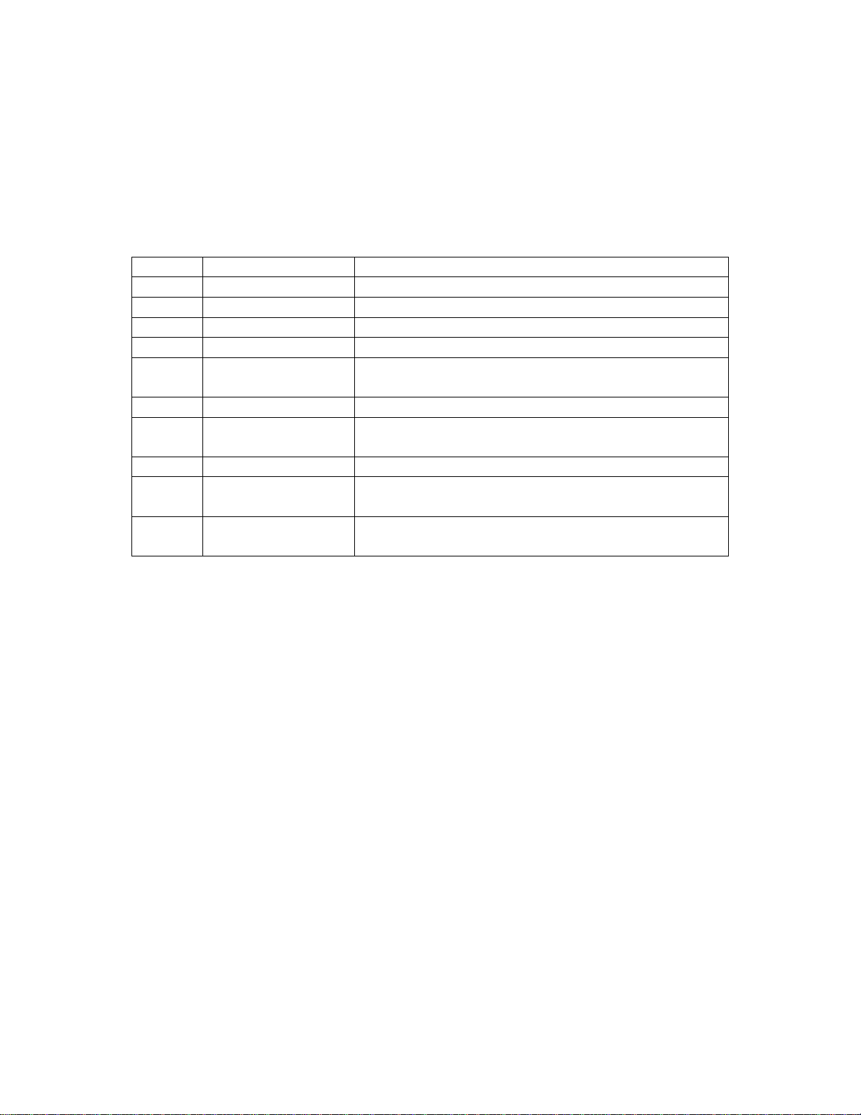
3.2.6 Error Messages
Table 3-6 lists the Error Messages for the IEEE-488 interface of the 1855 instrument. In
response to the command “SYSTem:ERRor?”, the 1855 unit responds with the error message
number and an error message string of up to 80 characters in length.
Table 3-6: Error Messages
Code Type Message
0 No error There is no error in the error queue
-102 Syntax error Invalid character exists in the command string.
-104 Data error Parameter is not defined in the command string.
-106 Illegal parameter Parameter is not a valid command.
-202 Conflicting Settings Command conflicts with instrument settings.
Example: Send ‘Trigger’ when mode is external.
-203 Data range Data exceeds the valid range.
-211 Data stale No resent measurement result.
Example: Send ‘Read?’ when in Standby status.
-224 Self-Test failed Self-test via remote interface (*TST) failed.
-225 Excess errors The error queue is full (more than 20 errors).
Queue cleared after power down or *CLS command.
-226 Query interrupted Device status changed after query sent.
Output buffer will be cleared
Interface Page 71 of 76
Page 72
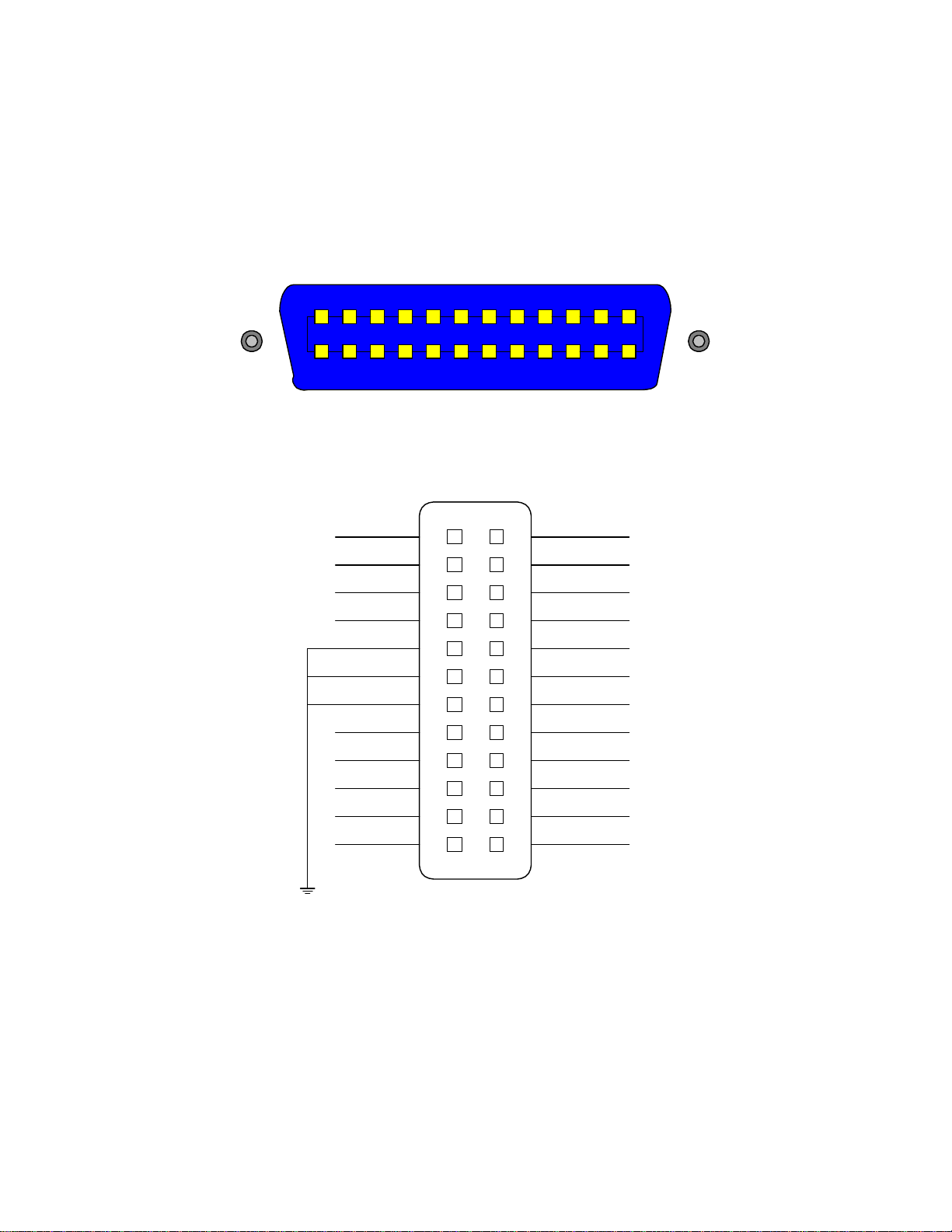
3.3 Handler Interface
There is an available Handler interface for the 1855 instrument as illustrated in Figure 3-4. [The
IEEE-488 and HANDLER interfaces come together as an optional accessory]. Connection to the
Handler interface is through the blue 24-pin connector labeled HANDLER on the rear panel of
the 1855 instrument.
1855 HANDLER Interface PIN Configuration: Rear Panel View
12 67891011
15 1419 18 17 162024 23 2122
1855 HANDLER Interface: PIN Designation
/EXT
N.C.
/TEST
FAIL HI
GND
GND
GND
COM
N.C.
VEXT
VINT
N.C.
1
2
3
4
5
6
7
8
9
10
11
12
13
14
15
16
17
18
19
20
21
22
/FAIL_CHARGE
23
24
/PASS
/CHARGE
/TEST
12534
13
N.C.
N.C.
/FAIL
EOT
/HI
/LO
ACQ
N.C.
Figure 3-4: Handler Interface Pin Configuration
Page 72 of 76 Interface
Page 73
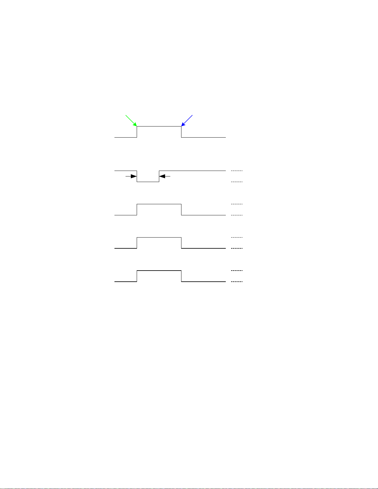
3.3.1 Trigger
Paragraph 2.3.16 contains the instructions for changing the Handler mode. Paragraphs 2.3.3 and
2.3.4 contain instructions for setting the Trigger Delay time and selecting the Trigger Edge.
Figure 3-5 illustrates the Trigger function.
Start measurement on RISING or FALLING edge
RISING FALLING
Trigger
DELAY
START
ACQ OVER
minimum
c
1uS
d
+2.5V < Vh < 5V
0V < Vl < 0.4V
Vh < 24V
Ih < 6mA (for Vl < +0.4V)
Vh < 24V
BIN
e
EOT
f
Ih < 6mA (for Vl < +0.4V)
Vh < 24V
Ih < 6mA (for Vl < +0.4V)
Figure 3-5: Trigger
Output Signals
The output lines of the 1855 Handler interface are open collector drivers that pull each signal line
to a low voltage, signal ground when the signal is active (true). Each external line should be
pulled up (with a resistor) to a positive voltage between 5V and 24V. The pull-up resistor must
limit the current to < 6mA for a signal of a comparison function and to < 5mA for a control
signal (EOT).
Input Signal
The input signal to the 1855 Handler interface is active low and requires a positive external
voltage to pull the signal down below 0.4V, ground.
Interface Page 73 of 76
Page 74

3.3.2 Handler Pin Assignments for Compare Operation
Table 3-7 lists the pin assignments when the handler interface on the 1855 instrument is
performing a Compare operation. The device under test is being compared against a standard of
known value. High and low limits can be defined as absolute value or percent value.
Table 3-7: Handler Pin Assignments for Compare
Pin Name Description
1 /EXT External trigger
2 X No connection
3, 20 /TEST Instrument is in Test mode
4, 24 X No connection
5 - 7 GND Ground external DC
8 COM Common Ground
9, 13 X No connection
10 VEXT External DC voltage: 5V ~ 24V
11 VINT Internal DC voltage: +5V
12 X No connection
14 X No connection
15 /PASS Measured Result is within the upper/lower limit(s) (PASS)
16 /CHARGE Instrument is in Charge mode
17 /FAIL Measured Result is outside the upper/lower limit(s) (FAIL)
18 /EOT End of Test
19 /HI For LC: Measured Result is > Upper Limit
For IR: Measured Result is < Lower Limit
21 /LO For LC: Measured Result is < Lower Limit
For IR: Measured Result is > Upper Limit
22 ACQ Received data, ready to accept next
23 EOT End of Test
45 – 46 /FAIL_CHARGE Instrument is in Discharge mode
NOTE:
When using External DC Voltage (VEXT), Pins 5, 6 & 7 (GND) must be connected to Pin 8
(COM).
Page 74 of 76 Interface
Page 75

Section 4: Service & Calibration
4.1 General
The warranty (at the front of this manual) attests to the quality of materials and workmanship in
QuadTech products. If malfunction should be suspected, or other information desired,
applications engineers are available for technical assistance. Applications assistance is available
in the U.S. by calling (978) 461-2100 and asking for Applications Support. For support outside
of the United States please contact your local QuadTech Distributor.
4.2 Instrument Return
Before returning an instrument to QuadTech for service please call our Customer Care Center
(CCC) at 800-253-1230 for Return Material Authorization (RMA). It will be necessary to
include a Purchase Order Number to insure expedient processing, although units found to be in
warranty will be repaired at no-charge. For any questions on repair costs or shipping instructions
please contact our CCC Department at the afore-mentioned number. To safeguard an instrument
during storage and shipping, please use packaging that is adequate to protect it from damage, i.e.
equivalent to the original packaging, and mark the box “Delicate Electronic Instrument”. Return
material should be sent freight prepaid to:
QuadTech, Inc.
5 Clock Tower Place, 210 East
Maynard, Massachusetts 01754
Attention: RMA#
Shipments sent collect cannot be accepted.
4.3 Calibration
Calibration of the 1855 Capacitor Leakage Current/IR Meter is completed at the factory and
includes a NIST calibration certificate. Verification of the instrument is recommended on an
annual basis. Accurate operation of the 1855 instrument is confirmed using the 1855-TP Test
Procedure.
Service & Calibration Page 75 of 76
Page 76

4.3.1 1855 Verification Procedure
This section outlines the relevant information to verify performance of the 1855 Meter. It is
recommended that performance be performed at least once a year using this outline procedure.
Instrument should be warmed up for a minimum of 15 minutes prior to verification. Verification
should be performed under the following conditions: Temperature equal to 23°C ±1.2°C and
Relative Humidity (RH) between 35% and 55%.
Recommended standards are listed below. All standards should be traceable to a National
Laboratory (such as NIST) and have calibrated values for primary and secondary parameters at
the required test frequencies. QuadTech’s verification conforms to ANSI Z540 and QuadTech
recommends that the calibrated values for the primary and secondary standards have an
uncertainty 4 times better than the primary and secondary accuracy specified in the Verification
Data Sheet. If the calibrated values for the standards used do not have an uncertainty of 4 times
better than the specified accuracy of the 1855 the uncertainty of the standard should be added to
the specified accuracy of the 1855.
4.3.2 1855 Verification Data Sheet
Out Voltage: @ 10mA
(Verify Display & Measured Values are within high and low limits)
(Note: MEASURE between RED (+) and WHITE (-) mounting jacks)
Voltage Setting
(V)
Measured
Voltage (Fluke)
Displayed
Voltage (1855)
Low Limit
Voltage
High Limit
Voltage
1 795mV 1.205V
50 49.55V 50.45V
200 198.8V 201.2V
400 397.8V 402.2V
600 596.8V 603.2V
IR Measurement: @ .5mA
(Note: MEASURE between BNC jack and WHITE (-) mounting jacks)
Nominal
Setting
(V)
100V 10M 0.805%
100V 100M 0.854%
200V 1G 0.973%
500V 1G 0.747%
Resistance
(Ω)
Actual
Resistance
(Ω)
Before After Voltage
Displayed
Value
(Ω)
Test
Specifications
Displayed
Value
(Ω)
Page 76 of 76 Service & Calibration
 Loading...