

Page 1

1689/1689M Precision
RLC Digibridge(R)
Instruction Manual
Foml1689-0120-06/D2
(C)QuadTech, Inc., 1992
5 Clock Tower Place, 210 East
Maynard, Massachusetts, U.S.A. 01754
March, 2000
Telephone 978-461-2100
Sales 800-253-1230
Facsimile 978-461-4295
Website www.quadtech.com
The material in this manual is for informational purposes only and is subject to change, without notice. QuadTech
assumes no responsibility for any error or for consequential damages that may result from the misinterpretation of any
procedures in this publication.
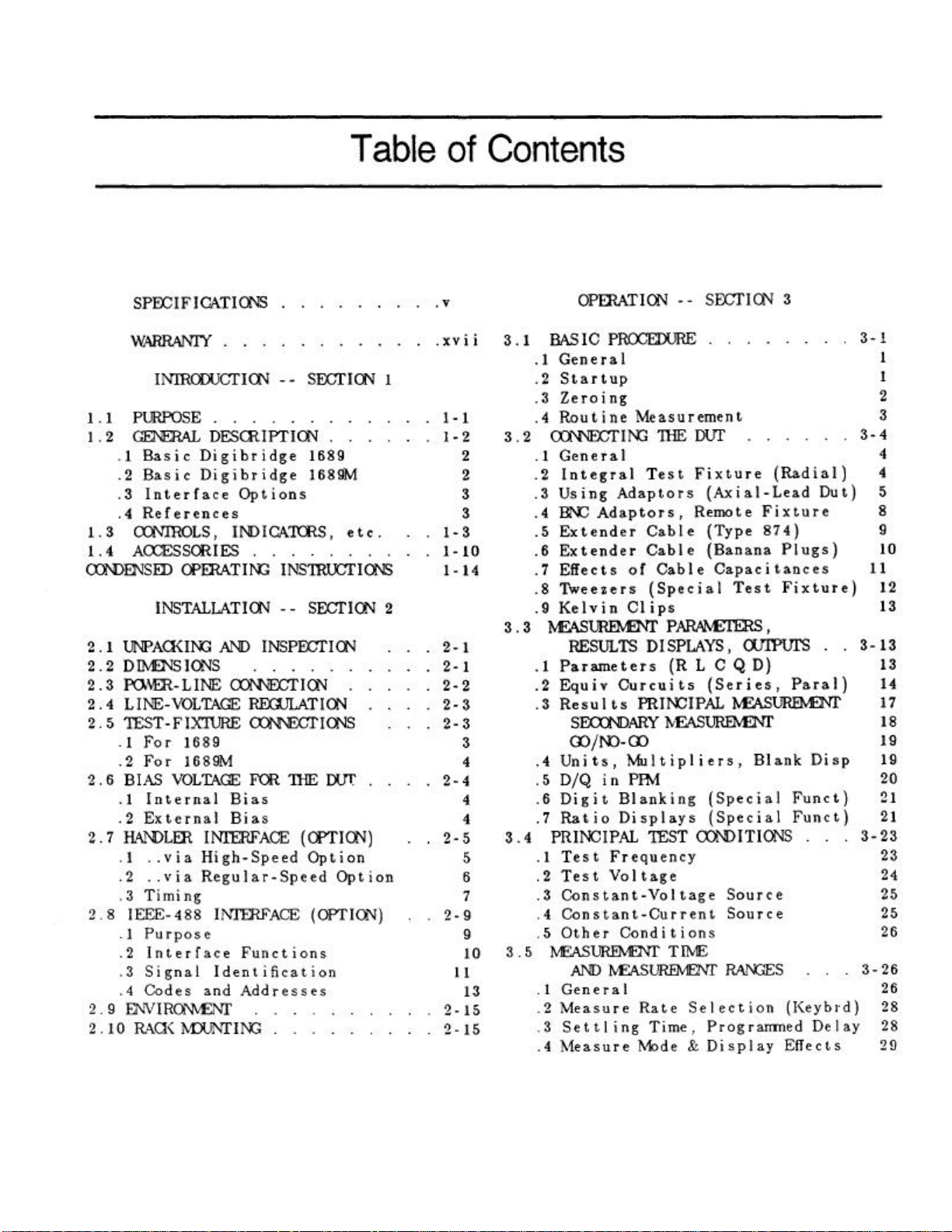
Contents
Specifications
Warranty
Introduction -Section 1
Installation - Section 2
Operation -Section 3
Theory -Section 4
Service and Maintenance -Section 5
Parts Lists and Diagrams -Section 6
Page 2
Page 3
Page 4
Page 5

Instruction Manual Changes (continued)
Page 5-41 -Table 5-7, Capacitance Accuracy Checks
1000 nF 600 ppm
.QDR Display Max column corrected as follows:
Nominal
Value QDR Max
10 pF 6100 ppm
100 pF 2500 ppm
1500 pF 700 ppm
1500 pF 1000 ppm
1500 pF 1700 ppm
6400 pF 500 ppm
10 nF 500 ppm
25 nF 500 ppm
25 nF 800 ppm
25 nF 1500 ppm
100 nF 500 ppm
200 nF 600 ppm
400 nF 600 ppm
400 nF 900 ppm
400 nF 1600 ppm
Page 6-2 -Figure 6-2, 1689 Rear View
Rear view should show new power supply assembly (PN 700011) without line
voltage switch.
Page 6-3 -Mechanical Parts List for 1689, Rear
Items 4 through 7 (power connector, fuse extractor post and line voltage switch and
cover) deleted on new power supply assembly.
Page 6-4 -Figure 6-2(A), 1689M Rear View
Rear view should show new power supply assembly (pN 700011) without line
voltage switch.
Page 6-5 -Mechanical Parts List for 1689M, Rear
Items 3 through 6 (power connector, fuse extractor post, line voltage switch and
cover) deleted on new power supply assembly.
Page 6-15 & Page 6-16 -Parts Lists and Diagrams
Power Supply Assembly shown, PN 1689-2005, has been replaced by Power
Supply Assembly, PN 700011. The 700011 Assembly must be repaired by module
exchange.
Page 6-19, 6-20, 6-21, & 6-22 -Parts Lists and Diagrams
High-speed interface board shown, PN 1689-4720, has been replaced by PN 1689
4620. See instructions supplied with the 1689-9630.
Page 6
ii
Page 7
iv
Page 8
Page 9

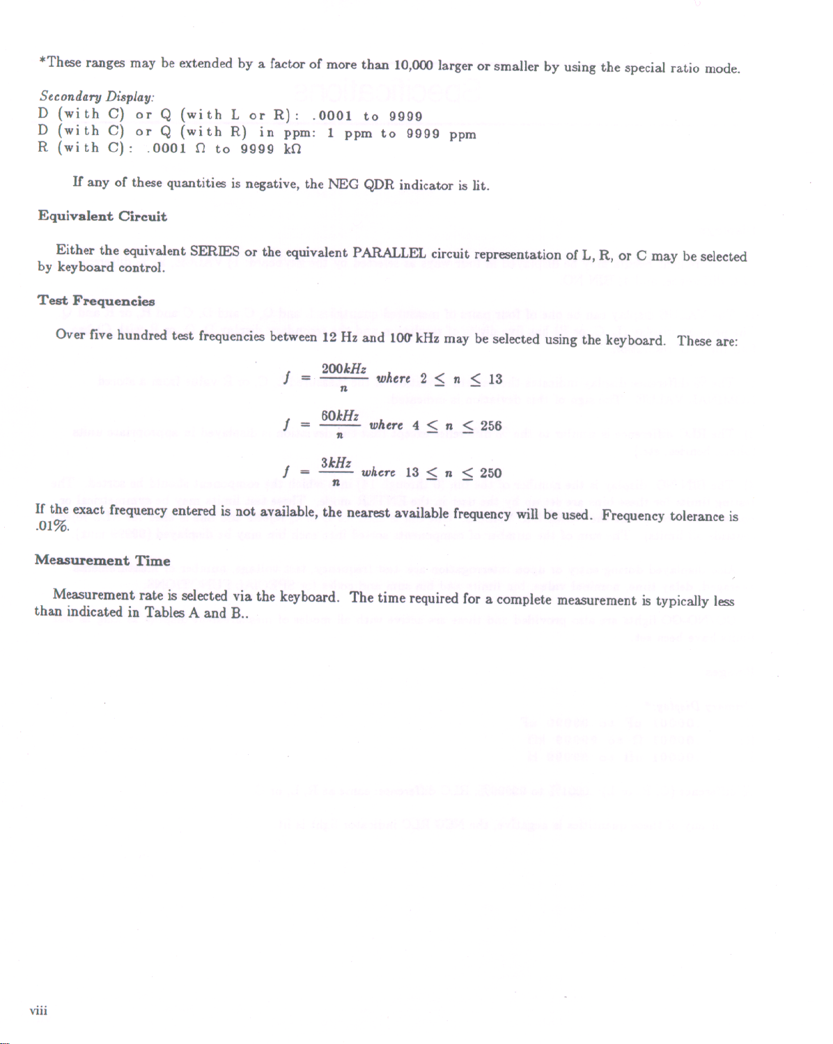
Displays
GO/NO-GO lights are also provided and these are active with all modes of measurement display as long as test limits have
vii
Measurement results may be displayed in four ways as selected by the keyboard: 1) VALUE, 2) % difference, 3)
RLC difference, and 4) BIN NO.
1) The VALUE display can be one of four pairs of measured quantities Land Q, C and D, C and R, or Rand Q. The primary
display (L, C, or R) has five digi~ of resolution and the secondary display D, Q, or R with C) has four digits of resolution.
2) The % difference display indicates the percent deviation of the measured L, C, or R value from a stored NOMINAL
VALUE. The sign of this deviation is indicated.
3) The RLC difference is similar to the % difference except that the deviation is displayed in appropriate units (ohms, henries,
etc.)
4) The BIN NO. display is the number of the bin (0 through 14) into which the component should be sorted. The testing limits
for these bins are set up by the user in the ENTER mode. These test limi~ may be symmetrical or non-symmetrical about the
NOMINAL VALUE. One bin is used for D or Q rejects and one is used for RLC rejects (outside all limits). The sum of the
number of componen~ sorted into each bin may be displayed (99999 max).
Also displayed during entry or upon interrogation are: test frequency, test voltage, number of measurcments
averaged, delay time, nominal value, bin limi~ and bin sum and codes for SPECIAL FUNCTIONS.
been set.
Ranges
Primary Disp/ay:*
C: .00001 pF to 99999 uF
R:
L:
% difference (C, R, or L): .0001% to 99999%; RLC difference: same as R, L, or C.
.000010 to 99999 kO
.00001 nH to 99999 H
If any of these quantities is negative, the NEG RLC indicator light is lit.
Page 10
Page 11

TABLE A
Test connections can be broken (handler indexing can begin) as soon as data acquisition is complete (ACQ
line low on handler interface). See Note 4 in tables.
i
x
GR1689 MEASUREMENT RATE
TEST FREQUENCY
MEASUREMENT
RATE 12 Hz 100 Hz 120Hz 1 kHz 10 kHz 100 kHz
SLOW 875 ms 940 ms 940 ms 970 ms 930 ms 930 ms
MEDIUM 670 ms 130 ms 185 ms 200 ms 190 ms 190 ms
FAST 670 ms 125 ms 110 ms 80 ms 75 ms 70 ms
MAX IMUM 670 ms 110 ms* 100 ms* 40 ms 34 ms 33 ms
Notes:1. If the high-speed option is not used, add 19 ms for MAXIMUM, or 38 ms
for SLOW, NEDIUM or FAST measurement.
2. If the display is value, delta%, or deltaRLC, add 6 to 10 ms.
3. If data is output via the IEEE Bus., add 6 to 12 ms.
4. For ACQ, subtract 22 ms for SLOW, MEDIUM or FAST and 12 ms for MAXIMUM.
TABLE B
GR1689M MEASUREMENT RATE
TEST FREQUENCY
MEASUREMENT
RATE 12 Hz 100 Hz 120 Hz 1 kHz 10 kHz 100 kHz
SLOW 875 ms 920 ms 920 ms 950 ms 920 ms 920 ms
MEDIUM 670 ms 120 ms 170 ms 180 ms 170 ms 170 ms
FAST 670 ms 105 ms 90 ms 65 ms 55 ms 55 ms
MAXIMUM 660 ms 101 ms* 86 ms* 32 ms 22 ms 22 ms
Notes: 1. If the high-speed option is not used, add 12 ms for MAXIMUM,
or 24 ms for SLOW, MEDIUM or FAST measurement.
2. If the display is value, delta% or deltaRLC, add 3 to 5 ms.
3. If data is output via the IEEE Bus, add 3 to 6 ms.
4. For ACQ, subtract 11 ms for SLOW, MEDIUM or FAST and 6 ms for MAXIMUM.
* These times can be shortened by 14 ms with reduced accuracy using the quick acquisition routine.
The measurement times are obtained with use of the high-speed measurement option, continuous
measurement mode, bin number display/handler output, and without IEEE-Bus data output. For other
conditions, refer to the table notes.
If the measurement mode is triggered, programmed delay (settling time), if any, should be added.
Normal power up conditions included a programmed delay of 7/f to 12/f ms depending upon
measurement rate. This delay can be programmed to zero or to any value up to 100 sec.
Page 12

Measurement
Modes
x
Two test modes are available: CONTINUOUS and TRIGGERED.
The CONTINUOUS mode makes successive measurements continuously, updating the display after each
measurement.
TRIGGERED measurements are initiated by the START button, or remotely from the IEEE bus or from the
Handler Interface, and the measurement result is displayed until the next measurement is started.
Average
The AVERAGE of any number of measurements from 1 to 255 may be made as desired in either of the two
MEASURE MODES. In the TRIGGERED mode, the running average is displayed and the final value held until the
START button is again depressed. In the CONTINUOUS mode, only the final value is displayed.
Test Voltage
The RMS test voltage is selectable from 5 mV to 1.275 V in 5 mV steps. The accuracy is: (5% + 2 mV) (1 + .001 f 2) where f
= frequency in kHz.
This voltage may be applied behind a source impedance (which depends on the range) in which case the selected voltage is
the maximum that will be applied and the voltage will be less at the low impedance end of each range. The voltage may be
applied also behind 25 ohms using the CONSTANT VOLTAGE function in which case the applied voltage will be constant
except when low impedances are measured.
Delay
A delay of from 1 to 99999 ms may be added to allow for settling of external switches and to permit a wider selection
of measurement rates.
DC Bias
An internal bias of 2 V may be applied to capacitors under test by means of the INT BIAS key.
An external bias of up to 60 VDC may be applied to capacitors under test using a panel switch. The applied
current should be limited to 200 mA.
The instrument is protected from damage from charged capacitors with a stored energy up to 1 joule at 60 volts or less.
Protection from higher voltages may be provided by external components.
Zeroing
Open: A simple OPEN operation removes the effects of stray capacitance and conductance of the internal test fixture or
any other test fixture or cable.
Short: A similar SHORT zeroing operation removes the effects of series resistance and inductance.
DUT Connections
The 1689 has a built-in test fixture that will accept radial or axial components. The 1689M has BNC
connectors for attachment to a wide variety of measurement accessories. Four terminal (Kelvin) connections are made to
the device under test. The instrument ground is guard for three-terminal measurements.
Page 13

Keyboard Lock
Xl
A combination of keyboard entries makes the keyboard inactive.
Special Functions
Several special features may bl;: :selected. These include:
Direct range setting
Range extension
Choice of integration time
Blanking of lesser digits
Signal Reversal to reduce hum pickup effects
Selection of the median value of three measurements
A routine that reduces transient delays when bias is applied
Automatic parameter selection
Quick acquisition routine
IEEE-488 Bus/Handler Interface Card (1658-9620)
IEEE-488 Bus (J2 on rear panel with option)
All front panel functions are programmable from the bus. All RLC, DQ, and bin data are available as output
to the bus. Output data format: ASCII or Binary.
The following functions, per IEEE-488, have been implemented:
AHI Acceptor Handshake (Listener)
SHI Source Handshake (Talker).
T5 Talker with normal and talk-only modes (for systems without a controller),
switch selectable on rear panel.
L4 Listener.
SRI Service Request (to request service when measurement is complete and the
instrument is not addressed to talk).
RL2 Remote/Local (no local lockout, no return-to-local switch).
PPO No par all e 1 po 11 .
OC1 Device clear.
DT1 Device Trigger (to start measurement).
CO No controller functions.
Handler Connections (JI rear panel with option)
1. Outputs, Active low: (Open collector drivers rated at 30 V max. Each will sink 16 mA at 0.4 V. External power and pull-up
resistors required).
Bin 0 through bin 9 (10 lines) -Sorting outputs.
ACQ OVER (1 line)-indicates end of data acquisition. Component may be removed (see TEST TIME).
EOT (1 line)-indicates end of test. Bin No. is valid.
2. Input, Active low:
(0 V < VI < 0.4 V, + 2.5 V < Vh < + 5 V)
Start (1 line)-Initiates new measurement.
Page 14
High-Speed Measurement/Interface Option 1689-9820)
Same as above option but also with high-speed capability to increase measurement rate and five more sorting bins (15
Primary Readout C, R, or L
xi
lines, open collector drives rated at 15 V max. Each will sink 24 mA at 0.5 V). See Measurement Rate specification, above.
Environment
Operating: O to 50 degrees C, 0 to 85% relative humidity.
Storage: -40 to 74degrees C.
When the high-speed option is used, the operating temperature range is O to 40 degrees C.
Temperature Effects (typical)
R, L or C: +/- 5 ppm/degree C.
Q or D: +/- [2 ppm/degree C + (3 ppm/degree C) x (frequency in kHz)]
All specifications refer to 23degree C (calibration temperature).
Power
90 to 125 V or 180 to 250 V AC, 50 to 60 Hz.
Voltage selected by rear panel switch; 50 watts maximum, 40 watts typical. When the high-speed option is
used, the maximum power is 60 watts.
Mechanical
DIMENSIONS (W x H x D):
1689 14.781 x 4.40 x 13.50 in. (375.4 x 111.8 x 342.9 mm) WEIGHT: 13 lbs. (5.9 kg.)
1689M 17.25 x 5.625 x 15.160 in. (438.15 x 142.87 x 385.06 mm) WEIGHT: 17 lbs. (7.71 kg.)
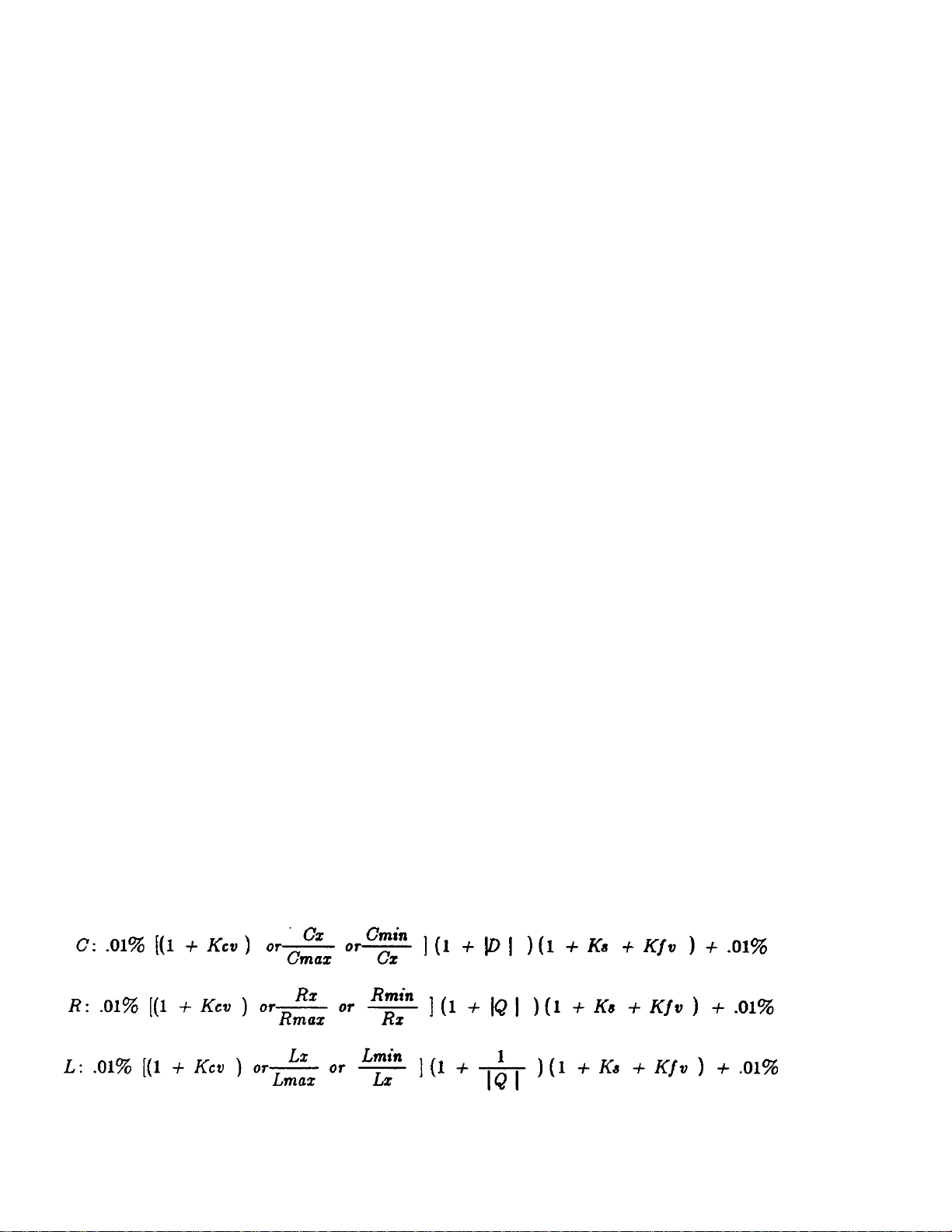
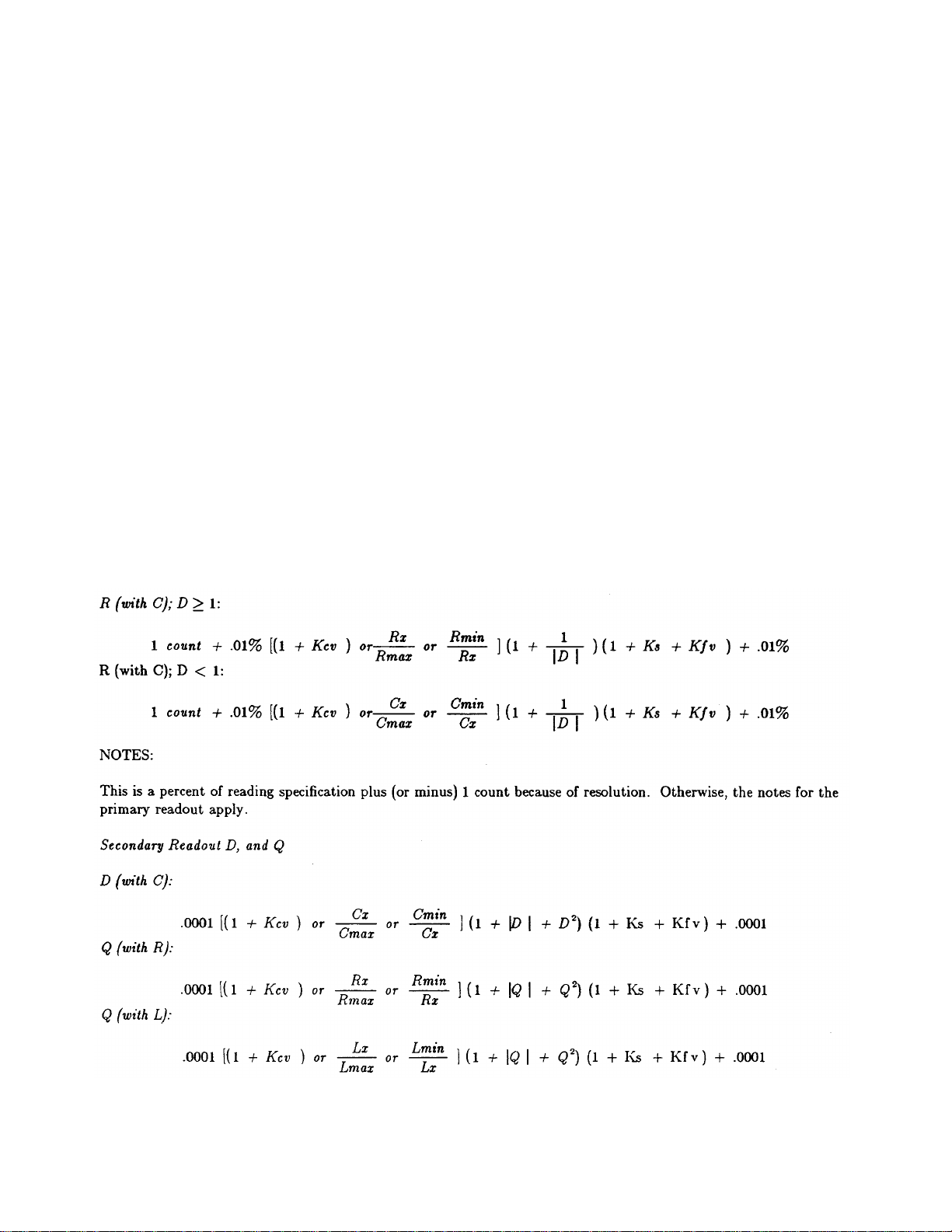
Limit or Error (Accuracy)
Page 15
NOTES:
xiii
1. The limit of error is a percent of the reading and may be positive or negative.
2. The largest term of the first bracketed factor should be used.
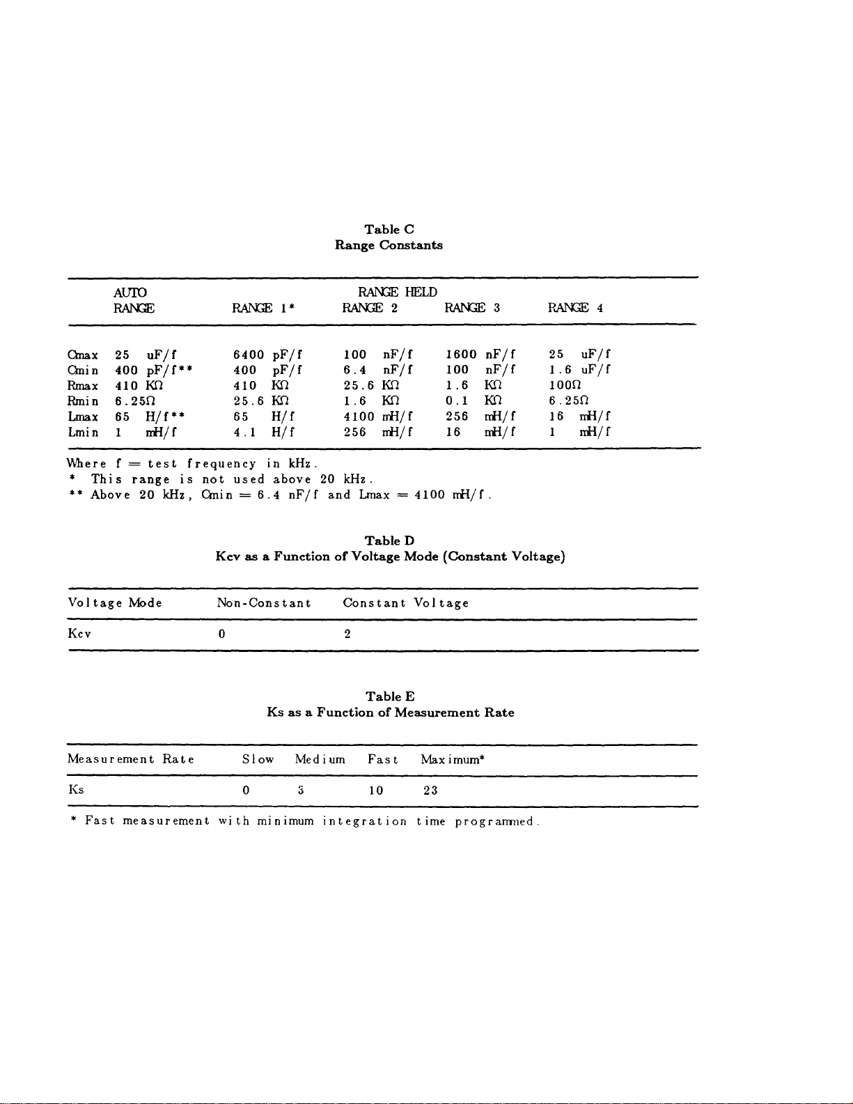
3. CX, RJc, and Lx are the values of the components being tested, and Cmax, Cmin, Rmax, etc., are range constants
given in Table C.
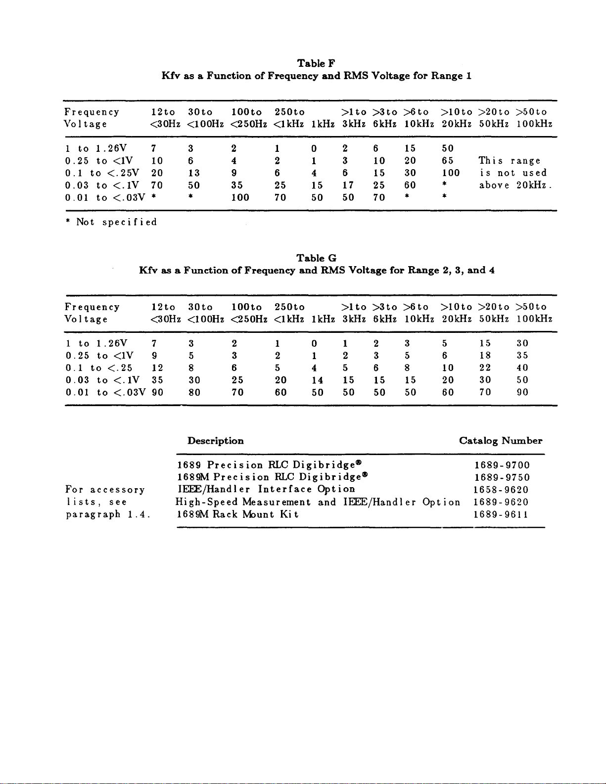
4. The values of Ks, Kfv, and Kcv are all zero for measurements made at 1 kHz, with the SLOW measurement rate and using a
non-CONSTANT 1 V signal. For other test conditions, these constants may be evaluated using Tables D through G.
5. These specifications assume proper OPEN and SHORT zeroing calibrations made at 1 kHz. Much better accuracy is
possible at extreme impedance values if these zeroing calibrations are recent and made at the test frequency to be used. For
example, the SLOW MEASUREMENT rate typically will give 1 % accuracy when measuring 100 Mohm at 30 Hz, 0.lF at 120
Hz, 0.1 pF at 10 kHz, or 0.1 uH at 100 kHz. Even better accuracy is possible if several measurements are averaged.
6. Although L measurements on the 1689 should be capable of the accuracy stated above, calibrations by the National Bureau
of Standards are specified to .02%; this amount should be added to the 1689 specification for inductance measurements if they
are to be used in any manner involving legal certification.
Secondary Readout R with C
Page 16
NOTES:
Otherwise, the notes for the primary readout apply. When using DQ in PPM, the final term of .0001 should be removed.
xiv
This is not a percent error but rather the amount, posiu've or negative, by which the D or Q reading may be in error.
Page 17
xv
Page 18

SERVICE POLICY
QuadTech policy is to maintain product repair capability for a period of five (5) years
after original shipment and to make this capability available at the then prevailing
schedule of charges.
Page 19
1.1 PURPOSE
INTRODUCTION 1-1
The two Digibridge(R) precision RLC testers, GR1689 and GR1689M, are microprocessor-controlled,
automatic, programmable RLC measuring instruments that provide high accuracy, convenience, speed,
and reliability at low cost. Limit comparison, binning, and internal bias are provided; both test frequency
and voltage are selectable. With an interface option, each Digibridge tester can communicate with other
equipment and respond to remote control.
The versatile, adaptable test fixture, lighted keyboard, and informative display panel make
these Digibridge testers convenient to use. Measurement results are clearly shown with decimal points
and units, which are automatically presented to assure correctness. Display resolution is 5 full digits for
R, L, and C (4 full digits for D, Q, Rs with Cs, and Rp with Cs). Notice that Rs is also known as ESR
(equivalent series resistance).
The basic accuracy is 0.02%. Long-term accuracy and reliability are assured by the
measurement system, which makes these accurate analog measurements over many decades of
impedance without any critical internal adjustments. Calibration to ..ccount for any change of testfixture parameters is semiautomatic; the operator needs to provide only open-circuit and short-circuit
conditions in the procedure. The Digibridge tester normally autoranges and automatically identifies the
principal measurement parameter.
The test fixture, with a pair of plug-in adaptors, receives any common component part (axiallead or radial-lead), so easily that insertion of the device under test (DUT) is a one-hand operation. True
4-terminal connections are made automatically. Extender cables are available for measurements at a
moderate distance from the instrument. They are optional for the 1689 (which has a built-in test fixture,
but requires extension typically for bulky components or parts in an automatic handler). They are
necessary for the 1689M, which has no built-in test fixture.
Limit comparisons facilitate sorting into 13 GO and 2 NO-GO bins.
Programmable test conditions include:
Page 20

Test frequencies from 12 Hz to 100 kHz
The essential front-panel features of the 1689 are provided on the vertical front of the model 1689M. These include the keypad,
1-2 INTRODUCTION
Test voltages from 5 mV to 1.275 V; bias (2 V)
Delay (before data acquisition) from zero to 99999 ms
Measurement speeds up to 45 per second (with 1689M) or 30 per second (with 1689)
Multi-measurement routines with automatic averaging and/or median taking of
2 to 765 measurements.
Displays: measured values, percentages, differences, ratios, GO/NO-GO, binning
Automatic output of value, bin number, bin summary and other results via IEEE-488
bus
Bias can be applied to capacitors being measured, either by programming the selection of an internal
supply (2 V) or by sliding a switch to connect an external voltage source (up to 60 V).
A choice between two interface options provides full "talker/listener" and "talker only" capabilities consistent with the
standard IEEE-488 bus. (Refer to the IEEE Standard 488-1978, Standard Digital Interface for Programmable Instrumentation. See
paragraph 2.8, in Section 2.) A separate connector also interfaces with component handling and sorting equipment.
1.2 GENERAL DESCRIPTION
1.2.1 Basic 1689 Digibridge
Convenience is enhanced by the arrangement of test fixture and controls on the front ledge, with all
controls for manual operation arranged on a lighted keyboard. Above and behind them, the display panel is inclined and recessed to
enhance visibility of digital readouts and indicators. These indicators and those at the keyboard serve to inform and guide the operator in
manipulating the simple controls, or to indicate that remote control is in effect.
The 1689 instrument stands on a table or bench top. The sturdy metal cabinet is durably finished, in keeping with the longlife circuitry inside. Glass-epoxy circuit boards interconnect and support high-quality components to assure years of dependable
performance. Although intended for bench-top use, this model can be rack mounted, using a type of mount that slides forward for
convenience.
Adaptability to any common ac power line is assured by the removable power cord and the convenient line-voltage switch.
Safety is enhanced by the fused, isolating power transformer and the 3-wire connection.
1.2.2 Basic 1689M Digibridge
display, and the power ON/OFF button. The set of four BNC connectors for connection to the test fixture is supplied on the front panel, but
can be relocated to the rear if that is preferred. The displaypanel and keyboard indicators serve to inform and guide the operator in
manipulating the simple controls, or to indicate that remote control is in effect.
The 1689M instrument also stands on a table or bench, where the bail provided under its front edge can be used to tilt it back
for operator convenience. This model goes particularly well in a rack, with its vertical front pane] and cable connection (from either front or
rear) to a suitable test fixture. The sturdy metal cabinet is durably finished, in keeping with the long-life circuitry inside. Glass-epoxy circuit
boards interconnect and support high-quality components to assure years of dependable performance.
Safety is enhanced by the fused, isolating power transformer and the 3-wire connection
Adaptability to any common ac power line is assured by the remo\rable power cord and the convenient line-voltage switch.
Page 21
1.2.3 Interface Options
INTRODUCTION 1-3
Either of the two interface options adds I/O capabilities to the instrument, enabling it to control and
respond to parts handling/sorting equipment. Also (via separate connector) either option can be connected in a measurement system using the
IEEE-488 bus. Either "talker/listener" or "talker only" roles can be performed by the Digibridge, by switch selection.
One of the interface options enables the Digibridge to measure at a higher speed than it does without an option. The high-speed
option provides outputs to 15 bins for sorting; the other option, to 10 bins.
1.2.4 References
Electrical and physical characteristics are listed in Specifications at the front of this manual. Interface connections and
instrument dimensions are given in Installation, Section 2. Controls are described below in Section 1; their use, in Operation, Section 3. A
functional description is given in Theory, Section 4.
1.3 CONTROLS, INDICATORS, AND CONNECTORS
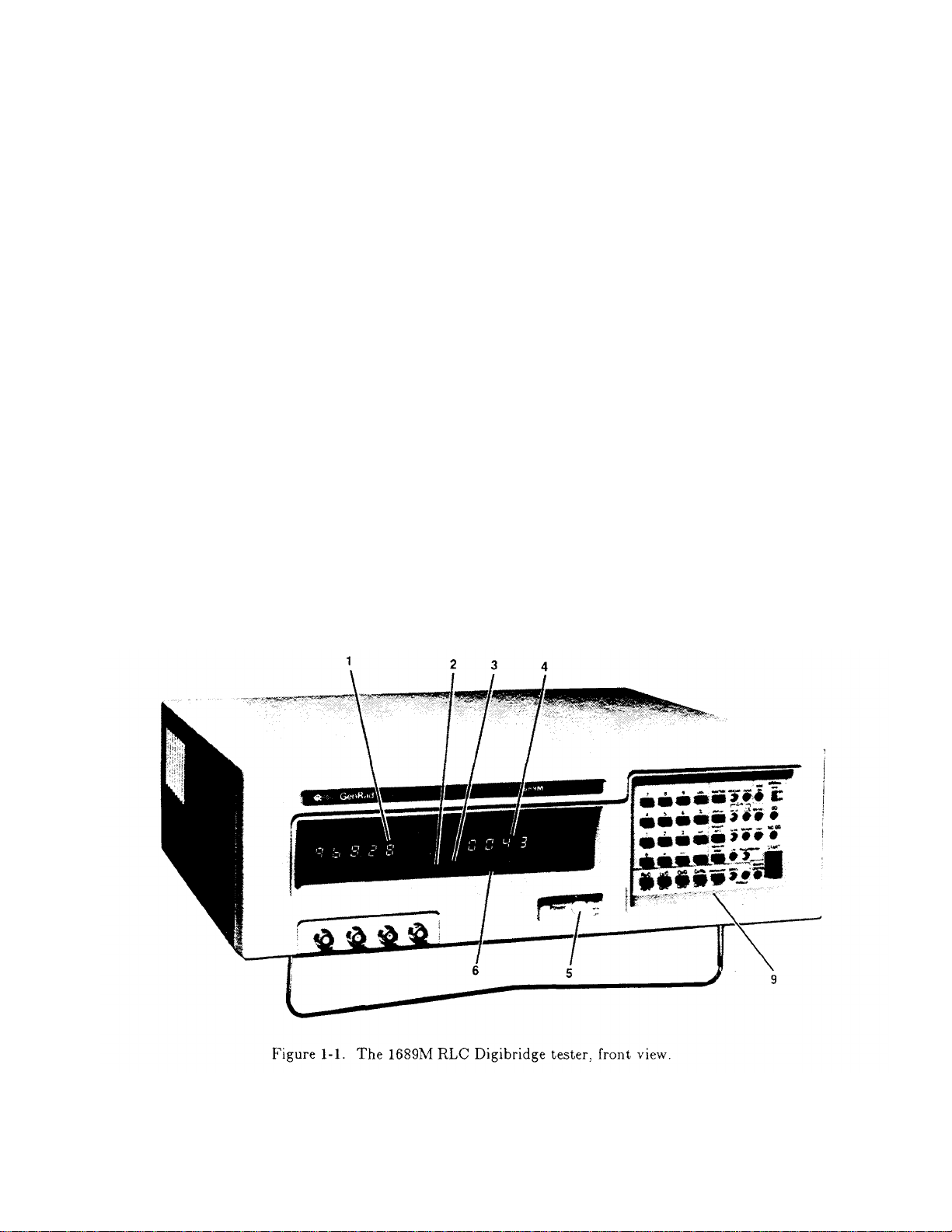
Figure 1-2 shows the controls and indicators on the front of the 1689 instrument. Table 1-1 identifies them with descriptions
and functions. Figure 1-1 shows the front of the 1689M model, which is functionally similar.
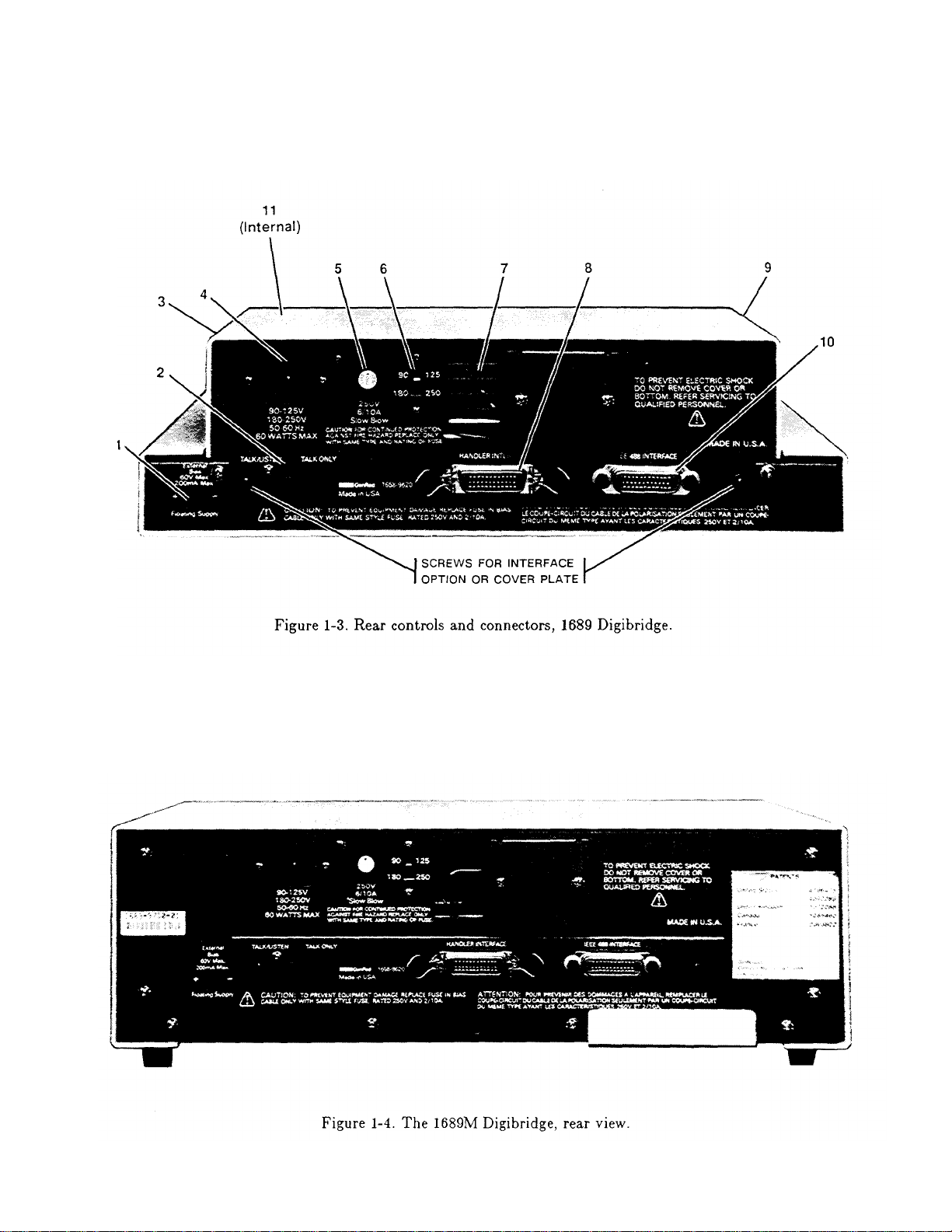
Similarly, Figure 1-3 shows the controls and connectors on the rear of the 1689; and Table 1-2 identifies them. Figure 1-4
shows the rear of the 1689M model, which is functionally similar.
Page 22

1-4 INTRODUCTION
Figure 1-2. Front controls and displays. Upper illustration: 1689 Digibridge tester, overall. Lower
illustration: keyboard detail.
Page 23

Table 1-1
Front Panel Controls and Indicators
Fig. 1-2
Ref No. Name Description Function
1 RLC display Digital display, Display of principal measured value.
5 numerals with If function is MEASURE and display
decimal points selection is VALUE, number indicates
R, L, or C. If display selection is delta% or deltaRLC, indicates
percentage difference (respectively) of R, 1, or C compared to
stored nominal value. If display selection is BIN NO., indicates
bin assignment of measured DUT. If function is ENTER,
displays are indications of programned entries,
special functions, bin sum, status in calibration sequences, etc.
2 Units and Light-spot (LED) Indicates measurement units associ~ted with
multipliers indicators RLC display and secondary display if it is
R. Indicates "%" if display selection
is delta%. None of these indicators
are lit if measurement display is "ratio".
3 "NEG" Light-spot (LED) NEG RLC and Nill Q)R indicate negative signs
indicators indicators associated with RLC and QDR displays.
(For explanations see paragraph 3.3.)
4 QDR display Digital display, If function is MEASURE, display of
4 numerals with secondary measured value or (i f display
decimal points is BIN NO.) blank. If function is ENTER,
RLC and Q)R displays together indicate
programned entries, special functions,
status in calibration sequences, etc.
5 POWER switch Pushbutton (push Switches the Digibridge ON (button in) and
again to release) OFF (button out). OFF position breaks both
sides of power circuit.
6 Other display- Light-spot (LED) RANGE HELD indicates that autoranging is
panel indicators disabled. CONST VOLT indicates that measure
indicators ment source resistance is fixed at a low
value. DQ, in PPM indicates that the D or Q
display is in parts per mi II ion.
7 Test fixture Pair of special Receives radial-lead DUT, making 4-ter
connector; each minal connection automatically. Adaptors
[Not on 1689M] axial-lead DUT. Extension cables
makes dual contact (supplied) make similar connection with
(5-terminal) are available.
Page 24

8 Reference card Captive pull-out Handy reference inforamtion for basic
1-6
INTRODUCTION
card operation: zeroing, making measurements,
[Not on1689M.] programming test conditions, limit entry,
and bin sorting.
9 Keyboard Group of keys, Manual programming and control. Refer to
indicators, and items 10 through 22 for more detai I,
2 other switches
10 Prograrmling Set of 16 keys, Multipurpose input of programning
keys labeled white and instructions, selections, and data,
yellow for 1689, Dual purposes of keys are indicated by
black and gray for color: White or black labels apply norm
1689M ally. Yellow or gray labels apply immed
iately after you press and release the
[SHIFT] key,
11 thru 14, Each key has Make selection by pressing key repeatedly
20, and 22 associated LED unti I the desired condition is indicated
(See below.) indicators at right of the key.
11 [FUNCTION] key Indicators MEASURE Selection of function. MEASURE enables
and ENTER. measurements and some routines that cannot
be done in ENTER, such as "zero" calibrations, keyboard lock or unlock, and
part
of full recalibration, ENTER enables programming of all special
functions, frequency, voltage, averaging, delay,
nominal value, and binning instructions, (Either function allows selection
of hold range, constant voltage, DQ in ppm, internal bias, parameter,
equivalent circuit, measure mode, measure rate, and
d i s play.)
12 [DISPLAY] key Indicators: VALUE, Selection of displays for MEASURE function;
13 [MEASURE RATE] Indicators: SLOW, Selection of measurernent speed as
delta%, BIN NO. refer to items 1, 2, and 4 for description
of displays. Two indicators are Lit
simultaneously for deltaRLC. This key
has no effect on ENTER function displays
key MED, FAST. i n d i cat e d. Spee d is also affectcd by
many other choices described in paragraph
3.5. Use SLOW for better accurac y, use
FAST for speed
Page 25

14 [MEASURE MODE] Indicators: CONT, Mode selection: CONT, continuously
Selection of principal measurement parameter
INTRODUCTION 1-7
key TRIGGERED repeating measurements; TRIGGERED,
single measurement initiated by START
button or input signal.
15 BIAS ON LED indicator Indicates that internal bias is on, or the
indi cator EXTERNAL BIAS swi tch is ON.
16 EXTERNAL BIAS Slide switch, 2 To connect and disconnect the external bias
switch positions: ON, circuit (rear connector, cable supplied).
OFF
17 GO/NO-GO Pair of LED GO means measured value is acceptable,
indicators indicators based on the limits previously stored.
(See paragraph 3.8.) NO-GO means RLC or QDR value or both are
unacceptable. Indicator remains lighted during next
me as u r erne n t .
18 START button Pushbutton switch. Starts measurement sequence (aborting any
measurernent that may be in process). Normally used in
TRIGGERED measure mode.
19 REMOTE OONTROL LED indicator Indicates when remote control is
indicator established by external command.
(Functions only if an interface option
is installed.)
20 EQUIVALENT Indicators: SERIES Selection of equivalent circuit. Measured
21 SHIFT key Key labeled SHIFT Pressing this shi fts the role of any
22 Parameter Set of 3 keys,
CIRCUIT key and PARALLEL principal R, L, C and secondary R values
(not D or Q) depend on this selection.
key labeled with both white and yellow
(or black and gray) F~ the white 1U yellow or black to gray. Do NOT hold
the the [SHIFT] key down; press it first,
then the other key.
keys labeled: R/Q, L/Q, --R, L, or C --and (for C only) secondary
C/D, and C/R, with parameter D or R. Repeated pushing of any
subscripts sand P one parameter key changes range in sequence
1 234 1 ...and hence measurement units.
Page 26
Page 27

1 EXTERNAL BIAS Connector, 2 pins, Receives cable (1658-2450, supplied) for
connector labeled 60 V max, external bias supply. Observe the voltage
200 rnA max, + -. and current limits and polarity.
2 TALK switch* Toggle switch. Selection of mode for IEEE-488 interface:
TALK/LISTEN or TALK ONLY, as labeled.
3 Air filter Porous plastic To prevent dirt from entering inlet vent.
sponge
4 Power connector Shrouded 3-wire AC power input. Use appropriate power cord,
labeled plug, conCorming with Belden SPH-386 socket or equivalent.
90-125 V, to International The GenRad 4200-0300 power cord (supplied)
180-250 V, Electrotechnical is rated Cor 125 V.
50-60 Hz, etc. Commission 320.
5 Fuse (labeled Fuse in Short circuit protection. Use Bussman
250 V, 1/2 A, extraction post type MDL or equivalent fuse, 1/2 A,
SLOW BLOW) holder 250 V rating.
6 Line-voltage Slide switch. Adapts power supply to line-voltage ranges,
switch Upper position: as indicated. To operate, use a small
90 to 125 V; screw driver, not a sharp object.
lower position,
180 to 250 V.
7 Vent Air passage Venti lation
8 HANDLER Socket, 24-pin; Connections to component handler (outputs
INTERFACE receives Amphenol are bin numbers and status; input is a
connector* "Microribbon" plug "start" signal).
P/N 5i-30240
(or equiv).
9 Vent Air passage Ventilation
10 IEEE-488 Socket, 24-pin. Input/output connections according to IEEE
INTERFACE Receives IEEE-488 Std 488-1978. Functions: complete remote
connector* interface cable. control. Output of selected resul ts, with
(See paragraph or without controller.
2 .8) .
Page 28

11 Fuse (1/4 A) Plug-in type,subs - Protects instrument circuitry from
information.
1-10 INTRODUCTION
miniature, quick- damage by charged capacitors.
acting. Manufactesr
Part No.273.250
by LITTLEFUSE, Inc.,
800 E.Northwest Hwy,
Des Plaines IL 60016
* TALK switch and 24-pin connectors are supplied with the interface option only.
1.4 ACCESSORIES
GenRad makes several accessories that enhance the usefulness of each Digibridge. The axiallead adaptors (provided) convert the test fixture to a configuration well suited for axial-lead
components. A choice of extender cables facilitates making connection to a parts handler or to any DUT
that does not readily fit the test fixture. Extender cables are available with your choice of banana plugs,
BNC, or type 874 connectors. Each cable branches into 4 parts, for true 4-terminal connections (and
guard) to the device being measured, without appreciable reduction in measurement accuracy. A remote
test fixture is available to receive hand-inserted components at a distance from the Digibridge.
Other useful accessories are offered. Refer to Tables 1-3, 1-4 and inquire at the nearest
Digibridge Technical Support Center. (Refer to the back of this manual.)
NOTE
The GenRad line of Digibridge test
fixtures, adaptors, and other accessories
does continue to be improved and
expanded. Inquire periodically at your
local GenRad sales office for the latest
Page 29

1 supplied Power cord, 200 cm (6.5 ft) long, 3-wire, AWG No.18, 4200-0300
with molded connector bodies. One end, with Belden
SPH-386 socket, fits instrument. Other end conforms
to ANSI standard C73.11-1966 (125 V max).
2 supplied Test-fixture adaptors, for axial-lead parts. 1657-5995
Replacements available: set of 4 adaptors
1 supplied Bias cable, with built-in fuse, to connect external 1658-2450
bias supply and switching circuit.
1 recornnended High-speed measurement and lEEE-488/handl er 1689-9620
interface option retrofit (plug-in).
OR
1 recornnended IEEE-488/handler interface option retrofit (plug-in). 1658-9620
1 recornnended Tweezers, for handl ing and measuring chip components 1689-9603
with terminals on opposite (aces. BNC connectors;
127-cm (50-inch) cable. Use with adaptor 1689-9601.
1 recornnended Kelvin CI ip Cable, (or measuring large, low 1689-9606
impedance components. Use with adaptor 1689-9601.
1 recornnended Extender cable for connection to parts handler, 1657-9600
large or remote DOT, custom test fixture, etc.
Length 100 cm (40 in). One end fits test fixture
of Digibridge; other end terminates in 5 stackable
banana plugs.
1 recornnended Test-fixture adaptor, for BNC cable. 1689-9601
1 recomnended B~ cable assembly, 4 color coded cables with known 1689-9602
"stray" parameters, 90 cm (36 in.) long.
1 recomnended Remote test fixture (I ike the fixture on t.he 1689-9600
Digibridge, adaptable in many ways), with BNC
connectors. (Use 1689-9601 adaptor and 1689-9602
cable.)
Page 30
1 recommended Remote test fixture (like the 1689-9600); also has 1689-9605
of America, 1 Panasonic Way, Secaucus, N.J. 07094).
(Supplied with BNC-to-banana-plug adaptors.)
1-12
INTRODUCTION
START bar, GO/NO-GO lights, which function only if
the Digibridge has an interface option. Use
1689-9601 adaptor and 1689-9602 cable (as well as the 1689-2400 cable,
included with this fixture).
1 available Extender cable for connection to standards, large 1688-9600
1 available Rack mount kit (slides forward for complete access). 1657-9000
1 recommended Calibration kit, contains six Kelvin-connected 1689-9604
1 replacement Battery (Note: shelf life, 10 years; I ife in 8410-3480*
*Use the following battery if available: Panasonic part number BR-2/3A-F1 (Matsushita Electric Corp.
or remote DUT, custom t est fix t u r e, dielectric
measurement cell, etc. Length 30 cm (12 in). One
end fits test fixture of Digibridge, other end
terminates in four type 874 coaxial connectors.
references (four precision resistances, open, and
short), that plug into the built-in or 1689-9600/9605
test fixture.
instrument is 5 to 10 years. Refer to paragraph
3.13. )
1 supplied Power cord, 200 cm (6.5 ft) long, 3-wire, 4200-0300
1 supplied Bias cable, with built-in fuse, to connect 1658-2450
1 supplied BNC cable assembly, 4 color coded cables with 1689-9602
AWG No. 18, with molded connector bodies. One
end, with Belden SPH-386 socket, fits instrument.
Other end conforms to ANSI standard C73.11-1966
(125 V max).
external bias supply and switching circuit.
known "stray" parameters, 90 cm (36 in.) long.
Page 31

1 recommended Tweezers, for handl ing and measuring chip 1689-9603
INTRODUCTION 1-13
components with terminals on opposite faces.
BNC connectors; 127 -cm (50 -inch) cable. (No
adaptor needed.)
1 recommended High-speed measurement and IEEE-488/handler 1689-9620
interface option retrofit (plug-in).
OR
1 recommended IEEE-488/handler interface option retrofit 1658-9620
(plug- in).
1 recommended Rack mount kit. (Digibridge front panel is always 1689-9611
accessible; the BNC connectors for cable to test
fixture can be mounted on either front or rear
pan e I .)
1 recommended Remote test fixture (like the 1689-9600); also has 1689-9605
START bar, GO/NO-GO I ights, which function only if Digibridge has an interface option. Use cables
1689-9602 (supplied with 1689M) and 1689-2400
(included with this fixture).
1 available Remote test fixture for radial-lead DUTs (I ike 1689-9600
test fixture on 1689 Digibridge), with BNC
connectors. Use 1689-9602 cable (supplied with
1689M). Use axial-lead adaptors (supplied) if
appropriate. Accepts other accessories, like
extender cables 1657-9600, 1688-9600. (See
Table 1-3).
2 (suppl ied Test-fixture adaptors, for axial-lead parts. 1657-5995
with fixture) Replacements available: set of 4 adaptors.
1 recommended Cal ibration kit, contains six Kelvin-connected 1689-9601
1 replacement Battery (Refer to information in preceding table.) 8410-3480
1 recommended Kelvin CI ip Cable, for measuring large, low 1689-9606
references (fuur precision resistances, open,
and short), that plug into the 1689-9605 or the
1689-9600 test fixture.
impedance components.
Page 32

1-14
INTRODUCTION
Page 33

INSTr\J,LATION :2-1
2.1 UNPACKING AND INSPECTION
If the shipping carton is damaged, ask that the carrier's agent be present when the instrument, is
unpacked. Inspect the instrument for damage (scratches, dents, broken parts, etc.), If the instrument, is damaged or fails to meet
specifications, notify the carrier and the nearest GenRad field office. (See list at back or this manual.) Retain the shipping carton and the
padding material for the carrier's inspection.
2.2 DIMENSIONS Figure 2-1.
The instrument is supplied in a bench configuration, i.e., in a cabinet with resilient feet for placement on a table. The
overall dimensions are given in the figure. The two cabinet styles differ as follows
keypad horizontal, display tiltcd keypad & display on front (vertical)
instrument does not tilt instrument tilts for convenience
test fixture provided on front test fixture always remote (BNC cables)
bench use primarily (rack possible) multiple use (rack, shelf, bench...)
Page 34

2.3 POWER-LINE CONNECTION Figure 2-2.
2-2 INSTALLATION
The power transformer primary windings can be switched, by means of the line voltage switch on the
rear panel, to accommodate ac line voltages in either of 2 ranges, as labeled, at a frequency of 50 or 60 Hz, nominal. Making sure that the
power cord is disconnected, use a small screwdriver to set this switch to match the measured voltage of your power line.
If your line voltage is in the lower range, connect the 3-wire power cable (P IN 4200-0300) to the power connector on the rear
panel (Figure 1-2) and then to the power line.
The instrument is fitted with a power connector that is in conformance with the International Electrotechnical Commission
publication 320. The 3 flat contacts are surrounded by a cylindrical plastic shroud that reduces the possibility of electrical shock whenever the
power cord is being unplugged from the instrument. In addition, the center ground pin is longer, which means that it mates first and
disconnects last, for user protection. This panel connector is a standard 3-pin grounding-type receptacle, the design of which has been
accepted world wide for electronic instrumentation. The connector is rated for 250 V at 6 A. The receptacle accepts power cords fitted with
the Belden type SPH-386 connector.
The associated power cord for use with that receptacle, for line voltages up to 125 V, is GenRad part no. 4200-0300. It is a 200cm (6.5 ft), 3-wire, 18-gage cable with connector bodies molded integrally with the jacket. The connector at the power-line end conforms to
the "Standard for Grounding Type Attachment Plug Caps and Receptacles", ANSI C73.11-1966, which specifies limits of 125 V and 15 A.
This power cord is listed by Underwriters Laboratories, Inc., for 125 V, 10 A.
If your power line voltage is in the higher range (up to 250 V), be sure to use a power cord that is approved for 250 V. The end
that connects to the Digibridgel8) tester should have a connector of the type that is on the power cord supplied; the other end, an approved
connector to mate with your standard receptacle. A typical configuration for a 250- V, IS-A plug is illustrated in the accompanying figure.
Page 35

Figure 2-2. Configuration of 250-V 15-A plug. Dimensions in mm. This is listed as NEMA 6-15P. Use for example Hubbell
INSTALLATION 2-3
plug number 5666.
2.4 LINE- VOLTAGE REGULATION
The accuracy of measurements accomplished with precision electronic test equipment operated from ac line
sources can often be seriously degraded by fluctuations in primary input power. Line-voltage variations of +/15% are
commonly encountered, even in laboratory environments. Although most modern electronic instruments incorporate some
degree of regulation, possible power-source problems should be considered for every instrumentation setup. The use of linevoltage regulators between power lines and the test equipment is recommended as the only sure way to rule out the effects on
measurement data of variations in line voltage.
2.5 TEST-FIXTURE CONNECTIONS
2.5.1 For the 1689 Digibridge
Because an unusually versatile test fixture is provided on the front shelf of the instrument, external
test-fixture connections are generally NOT required. Simply plug the device to be measured (DUT) into the test fixture, with
or without its adaptors. For details, refer to paragraph 3.2.
Accessory extender cables arc available to connect to a DUT that is multiterminal, physically large, or otherwise
unsuited for the built-in test fixture. Extender cables are needed, similarly, to connect from the Digibridge test fixture to the
DUT socket in a mechanical parts handler. Cables and adaptors are listed in Table 1-3. Connection details are given in
paragraph 3.2.
NOTE
The GenRad line of Digibridge test fixtures,
adaptors, and other accessories does continue
to be improved and expanded. Inquire
periodically at your local GenRad sales office for
the latest information.
Page 36

2.5.2 For the 1689M Digibridge
2-4 INSTALLATION
An external test fixture is always required, because connection from the 1689M Digibridge to the DUT is
provided via BNC cables (from connectors that can be positioned at either front or rear of the instrument, as described in
Section 5). For general purposes, the recommended test fixture, cable, and their connections are as follows. Refer to
paragraphs 1.4 and 3.2 for more information about accessories.
COMMENT: It is important that the n. and PL leads connect to the same end of the DUT (and that PH and IH
connect to the other end). Also, for the 1689 and 1689M Digibridges, connecting IL/PL to the testfixture connectors
labeled "+" (and IH/PH to "-") assures that the test fixture's "+" and "-" labels agree with the bias polarity.
NOTE: In the cable's color code, RED is associated with "hot" leads, which have dc voltage, negative with
respect to ground, when bias is used.
2.6 BIAS VOLTAGE FOR THE DUT
2.6.1 Internal Bias
No external connections are required for the internal 2-volt bias. The circuit is self contained.
2.6.2 External Bias
External bias can be provided by connecting a suitable current-limited, floating dc voltage source, as
follows.
Be sure that the voltage is never more than 60 V, max.
A current limiting voltage supply is recommended; set the limit at 200 mA, max.
Be sure that the bias supply is floating; DO NOT connect either lead to ground.
A well filtered supply is recommended. Bias-supply hum can affect some
measurements, particularly if test frequency is the power frequency.
Generally the external circuit must include switching for both application of bias after
each DUT is in the test fixture and discharge before it is removed.
Connect the external bias voltage supply and switching circuit,
using the 1658-2450 cable, supplied, via the rear-panel EXTERNAL BIAS connector.
Observe polarity marking on the rear panel; connect the
supply accordingly.
Page 37

2.7 HANDLER INTERFACE (OPTIONAL)
2.7.1 Interface via High-Speed Measurement / Interface Option (1689-9620)
If you have the 1689-9620 High-Speed Measurement / IEEE-488 Bus / Handler Interface Option,
connect from the HANDLER INTERFACE on the rear panel to a handler, printer, or other suitable peripheral equipment as
follows. (The presence of the 24-pin connectors shown in Figure 1-3 verifies that you have one of the interface options; see
also paragraph 2.7.2.) Refer to Table 1-2 for the appropriate connector to use in making a cable. Refer to Table 2-1 for the key
to signal names, functions, and pin numbers.
Connect the bin control lines to the handler. See Table 2-1. Notice that the 1689-9620 High-Speed Measurement
Option provides outputs for automatic sorting into 15 bins. (Refer to paragraph 3.8.)
As indicated in the Specifications at the front of this manual, the output signals come from opencollector drivers
that pull each signal line to a low voltage when that signal is active and let it float when inactive. Each external circuit must be
powered by a positive voltage, up to 15 V (max), with sufficient impedance (pull-up resistors) to limit the active-signal (logic
low) current to 24 mA (max).
CAUTION
Provide protection from voltage spikes over 15 V.
The cautionary note above means typically that each relay or other inductive load requires a clamping
diode (rectifier) across it (cathode connected to the power-supply end of the load).
The input signal is also active low and also requires a positive-voltage external circuit, which must pull the signal
line down below 0.4 V, but not less than 0.0 V, i.e., not negative. The logic-low current is 0.4 mA (max). For the inactive state
(logic high), the external circuit must pull the signal line above +2.5 V, but not above +5 V.
NOTE
The "end of test" signal EOT is provided by the
Digibridge only while binning is enabled, by
having a non-zero "nominal value" in memory.
Refer to paragraph 3.8 for details.
Page 38

2.7.2 Interface via IEEE-488 Bus / Handler Interface Option (1658-9620)
2-6 [1\,"STALLATION
panel to a handler, printer, or other suitable peripheral equipment as follows. (The presence of the 24-pin connectors shown in Figure 1-3
verifies that you have one of the interface options; refer to paragraph 2.7.1 ) Refer to Table 1-2 for the appropria.te connector to use in
making a cable. Refer to Table 2-1 for the key to signal names, functions, and pin numbers.
If you have the 1658-9620 interface option, connect from the HANDLER INTERFACE on the rear
Page 39

Connect the bin control lines to the handler. See Table 2-1. Notice that the 1658-9620 IEEE-488 Bus /
INSTALLATION 2-7
Handler Interface Option card provides outputs for automatic sorting into 10 bins. (Refer to paragraph 3.8.)
As indicated in the Specifications at the front of this manual, the output signals come from open
collector drivers that pull each signal line to a low voltage when that signal is active and let it float when inactive. Each
external circuit must be powered by a positive voltage, up to 30 V (max), with sufficient impedance (pull-up resistors) to limit
the active-signal (logic low) current to 16 mA (max).
CAUTION
Provide protection from voltage spikes over 30 V.
The cautionary note above means typically that each relay or other inductive load requir es a clamping
diode (rectifier) across it (cathode connected to the power-supply end of the load).
The input signal is also active low and also requires a positive-voltage external circuit, which must pull the signal
line down below 0.4 V, but not less than 0.0 V, i.e., not negative. The logic-low current is 0.4 mA (max). For the inactive
state (logic high), the external circuit must pull the signal line above +2.5 V, but not above +5 v.
Figure 2-3. Handler interface timing diagram. External circuit must keep a-b > 1 us, and (if START is not "debounced")
a-c < [the settling time or programmed delay]. For single measurements, the DUT can be disconnected after e. The
selected BIN line goes low at f; the other BIN lines stay high. For MEDIAN and/or AVERAGE measurement routines,
ACQ OVER goes low (e) at the end of the last measurement.
2.7.3 Timing Figure 2-3.
(minimum) in each state (high and low). If START is provided by a mechanical switch without debounce circuitry, the
Digibridge will make many false starts; if START does not settle down (low) within the default settling time or the
programmed delay time after the first transition to high, the measurement time may increase substantially. For an explanation
of settling and delay time, refer to paragraph 3.5.3.
Refer to the accompanying figure for timing guidelines. Notice that START must have a duration of 1 us
Page 40

Measurement starts at time d, which is essentially the same as time b or c; measurement is completed at g. (The
2-8 INSTALLATION
START signals are expanded for clarity.) Interval a-e, during which the DUT must remain conllected for data acquisition, is
considerably shorter than the total measurement time a-g. The DUT can be changed after e ("indexing on ACQ", to save time)
or after g ("indexing on EOT", for a simpler test setup), as explained below.
After the calculation interval e-f, measurement results are available for sorting, i.e., one of the BIN lines goes low.
A few micro-seconds later, EOT goes low (can be used to set a latch holding the bin assignment). ACQ OVER, the selected
BIN line, and EOT then stay low until the next start command.
The time required for measurement depends on whether you have the high-speed measurement option, on test
conditions, programmable values, and operating selections. Interval a-e can be less than 15 ms; the cycle ag can be less than 40
ms; refer to paragraph 3.5 for details.
Set up the handler either of two ways: indexing on EOT or indexing on ACQ, as follows. The handler must supply
a signal (here called "start next measurement") when it has completed connection of the DUT to the test fixture.
Indexing on EOT, Set up the handler to respond to the EOT signal from the Digibridge, which occurs at the "end of
test", when the bin assignment is available for sorting. Set up the Digibridge to receive its START signal from the handler's
"start next measurement" signal. This setup is simpler than the one below.
NOTE
The Digibridge requires that a non-zero value
be entered for "nominal value" to enable
generation of the EOT signal and indication
by the GO/NO-GO lights; see paragraphs
3,8.3, 3,8,4.
Indexing on ACQ. Set up the handler to respond to the ACQ OVER signal from the Digibridge, which occurs when
the "data acquisition" is complete, The handler can then remove the DUT from the test fixture and replace it with another DUT,
while the Digibridge is calculating the result,
In addition, set up an interface that provides a START signal to the Digibridge by logical combination of the EOT
signal from the Digibridge AND the "start next measurement" signal from the handler. Indexing on ACQ results in higher
measurement rate than indexing on EOT.
Be sure the TALK switch is set to TALK ONLY, if the IEEE-488 bus is not used.
Page 41

Figure 2-4. Block diagram of a generalized system interconnected by the 16-signal- line bus specified in the IEEE Standard 488.
Reprinted from Electronics, November 14, 1974; copyright McGraw-Hill, Inc., 1974.
2.8 IEEE-488 INTERFACE (OPTION)
2.8.1 Purpose Figure 2-4.
If you have either interface option, you can connect this instrument to a printer or into a system
(containing a number of devices such as instruments, apparatus, peripheral devices, and generally a controller or computer) in which each
component meets IEEE Standard 488-1978, Standard Digital Interface for Programmable Instrumentation. A complete understanding of
this Standard (about 80 pages) is necessary to understand in detail the purposes of the signals at the IEEE-488 INTERFACE connector at
the rear panel of this instrument.
NOTE
For copies of the Standard, order "IEEE Std
1978, IEEE Standard Digital Interface for Programmable
Instrumentation", from IEEE
Department PB-8, 445 Hoes
08854.
To make connection to a single device like a printer, use a IEEE-488 cable, which fits the rear-panel connector labeled IEEE488 INTERFACE. For larger systems, each device is connected to a system bus, in parallel, usually by the use of several stackable cables.
Refer to the figure for a diagram of a hypothetical system. A full set of connections is 24 (16 signals plus shield and ground returns), as
tabulated below and also in the Standard. Suitable cables, stackable at each end, are available from Component Manufacturing Service, Inc.,
West Bridgewater, MA 02379, U.S.A. (Their part number 2024/1 is for a I-meter-Iong cable.)
Service Center,
Lane, Piscataway, N. J.
488-
Page 42

This instrument will function as either a TALK/LISTEN or a TALK ONLY device in the system, depending on the position
identifications below. For example, T5 represents the most complete set of talker capabilities, whereas PPO means the absence of a capability.
2-10 INSTALLATION
of the TALK switch. "TALK/LISTEN" denotes full programmability and is sllited for use in a system that has a controller or computer to
manage the data flow. The "handshake" routine assures that the active talker proceeds slowly enough for the slowest listener that is active,
but is not limited by any inactive (unaddressed) listener. TALK ONLY is suited to a simpler system -e.g. Digibridge and printer --with 110
controller and no other talker. Either mode provides measurement results to the active listeners in the system.
2.8.2 Interface Functions Figure 2-5.
The following functions are implemented. Refer to the Standard for an explanation of the function subsets, represented by the
SHI, source handshake (talker)
AHI, acceptor handshake (listener)
T5, talker (full capability, serial poll)
L4, listener (but not listen-only)
SRI, request by device for service from controller
RL2, remote control (no local lockout, no return-to-local switch)
PP0, no parallel poll
DC1, device clear
DT1, device trigger (typically starts measurement)
C0, no controller functions.
The handshake cycle is the process whereby digital signals effect the transfer of each data byte by means of status and control
signals. The cycle assures, for example, that the data byte has settled and all listeners are ready before the talker signals "data valid".
Similarly, it assures that all listeners have accepted the byte before the talker signals "data not valid" and makes the transition to another byte.
Three signal lines are involved, in addition to the 8 that convey the byte itself. Refer to the accompanying figure.
Page 43

Figure 2-5. The handshake process, illustrated by timing diagrams of the pertinent signals for a system with one talker and
INSTALLATION 2-11
several listeners. For details, refer to the standard.
2.8.3 Signal Identification
Refer to Table 2-2 for a key to signal names, functions, and pin numbers. Further explanation is found in the
Standard. The first three signals listed take part in the "handshake" routine, used for any multiline message via the data bus; the
next five are used to manage the flow of information; the last eight constitute the multiline
message data bus.
Page 44

2-12 INSTALLATION
Page 45

2.8.4 Codes and Addresses
INSTALLA TION 2-13
General. The device-dependent messages, such as instrument programming commands and measurement
data (which the digital interface exists to facilitate), have to be coded in a way that is compatible between talkers and listeners. They have to
use the same language. Addresses have to be assigned, except in the case of a single "talker only" with one or more "listeners" always
listening. The Standard sets ground rules for these codes and addresses.
In this instrument, codes for input and output data have been chosen in accordance with the rules. The
address (for both talker and listener functions) is user selectable, as explained below.
Instrument Program Commands. The set of commands used in remote programming is an input data code to which the
instrument will respond as a "talker/listener", after being set to a remote code and addressed to listen to device-dependent command strings.
The set includes all of the keyboard functions except switching
external bias ON/OFF and full recalibration, which are not remotely programmable.
Refer to paragraph 3.12.3 for a table of the commands used in programming.
Address. The initial setting of address, provided by the factory, is binary 00011. Consequently, the
talk-address command (MTA) is C in ASCII code and, similarly, the listen-address command (MLA) is #. If a different address pair is
desired, set it manually using the following procedure.
WARNING
Because of shock hazard and presence of electronic
devices subject to damage by static electricity (conveyed
by hands or tools), disassembly is strictly a "service"
procedure.
a. Take the Digibridge to a qualified electronic technician who has the necessary equipment for minor disassembly and
adjustment. Have the electronic technician remove the interface option assembly, as described in the 1689 Digibridge Service instructions.
(There is no need to remove the top cover first.)
b. Set the switches in "DIP" switch assembly S2 to the desired address, which is a 5-bit binary number.
(See below.)
c. Replace the interface option assembly in its former place.
Notice that S2 is located at the end of the interface option board, about 3 cm (1 in.) from the TALK
switch SI. If S2 is covered, lift the cover off, exposing the "DIP" switch, which has 6 tiny switches, numbered 1 thru 6. To enter logical 1 's,
depress the side of each switch nearest the end of the board (switch open). To enter logical O's, depress the other side of the switch (switch
closed). The address is read from 5 to 1 (not using 6). Thus, for example, to set up the address 00011, enter O's at positions 5,4,3; enter l's at
positions 2, 1. (This makes the talk address "C" and the listen address "#".) Strictly speaking, the address includes more; S2 determines only
the device-dependent bits of the address. You cannot choose talk and listen addresses separately, only as a pair. The list of possible pairs is
shown in Table 2-3.
Page 46

2-14 INSTALLATION
* Do N:::Yr set the swi tch to 11111, because a talk address of "-" would be confused with an "untalk" comnand, and a
I isten address of "?" with an "unl isten" comnand. (ASCII code for "-" is
1 011 III and for "?" is 0 III Ill.)
Page 47

In the above example, the remote message codes MLA and MTA are X0100011 and X100001 J , respectively. Thus the listen
INSTALLATION 2-15
address and the talk address are distinguished, although they contain the s;\me set of device-dependent bits, which you set into S2.
Data Output. Data (results of measurements) are provided on the DIO1...DI07 lines as serial strings of characters. Each
character is a byte, coded according to the 7-bit ASCII code, as explained above. The alphanumeric characters used are appropriate to the
data, for convenience in reading printouts. The character strings are always provided in the same sequence as that tabulated in paragraph
3.12.3; for example: RLC value, QDR value, bin number --if all 3 were selected (by the X7 command). The carriage-return and line-feed
characters at the end of each string provide a printer (for example) with the basic commands to print each string on a separate line.
For example, if the measurement was 0.54321 uF (1 kHz, range 4 held), the character string for RLC value is:
U(space )C(space )uF(2 spaces )0.54321( CR)(LF).
If the D measurement was .001, the character string for QDR value is:
(2 spaces)D(5 spaces)00.0010(CR)(LF).
If the measurement falls into bin 9, the character string for bin number is:
F(space)BIN(2 spaces)9(CR)(LF).
The character string for RLC value has the length of 17 characters; for QDR value, 17 characters; for
bin number, 10 characters -including spaces, carriage-return, and line-feed characters. Refer to the format tables in paragraph 3.12.2 for
details.
2.9 ENVIRONMENT
The Digibridge can be operated in nearly any environment that is comfortable for the operator. Keep the instrument and all
connections to the parts under test away from electromagnetic fields that may interfere with measurements.
Refer to the Specifications at the front of this manual for temperature and humidity tolerances. To safeguard the instrument
during storage or shipment, use protective packaging. Service personnel refer to Section
When the Digibridge is mounted in a rack or other enclosed location, make sure that the ambient temperature inside the rack
does not exceed the limits specified under "Environment" in the Specifications at the front of this manual, and that air can circulate freely
past all air inlet and outlet vents.
5.
2.10 RACK MOUNTING
1689-9611, For 1689M Digibridge. The 1689M Digibridge is more readily mounted in a rack than the
1689. Use this procedure.
a. If the location of the four BNC connectors (for test-fixture cables) is satisfactory, go on to the next step. Otherwise, the
BNC connector location can be moved from front to rear (or vice versa); this is a SI;:RVICE procedure, described in Section .5, paragraph
5.5.
Page 48

b. Preassemble the instrument with the shelf of the 1689-9611 Rack Mount Kit, as follows. Place the instrument on the shelf so
2-16 INSTALLATION
that its feet drop through the large holes. Lift the shelf up snugly under the instrument and secure them together with a No. 10-32 screw
through the small hole centered at the rear of the shelf, into the corresponding tapped hole in the instrument's rear panel.
NOTE
This screw is important for electrical
grounding, as well as for mechanical security.
c. position this assembly in the rack as desired and fasten the shelf at the front of the rack, using the four dress screws,
supplied. If the rack's mounting holes are tapped with number 10-32 threads, the nuts supplied for these screws can be omitted.
1657-9000, For 1689 Digibridge. The 1689 Digibridge can be mounted in a rack, using hardware that
permits sliding the instrument forward for access. Use this procedure.
a. Obtain the 1657-9000 Slide Rack Mounting Kit, which includes the 1657-3100 sliding shelf assembly,
instructions, and hardware.
b. Mount the shelf and slides in the rack, using the screws provided. Fasten the assembly at the front
and rear of the rack. Slide the shelf forward for access.
c. Remove the four screws from the bottom of the Digibridge and slide the instrument out of its bottom
shell.
d. Remove the four rubber feet from the bottom shell.
e. Place the bottom shell on the slide rack shelf and align it so that four small holes in the shelf appear
centered through the four large holes in the shell. Fasten the shell to the shelf through these four holes using 10-32
screws, provided, as follows. Place a large washer under the head of each screw, which is then run through the hole in the shelf; place lock
washer and nut on the end of the screw and tighten.
f. Slide the instrument into its bottom shell and reinstall the four screws removed in step c. (Large clearance holes are provided
in the shelf for access.) This completes the installation.
Page 49

3.1 BASIC PROCEDURE
3.1.1 General
For initial familiarization with the Digibridge(R) RLC tester, follow this procedure carefully. After that, use this paragraph as a
ready reference and refer to later paragraphs in this section for details. Condensed operating instructions are provided in Section 1.
Users of the 1689 Digibridge (not the 1689M), refer also to the Condensed Operating Instructions, found
stored in a pocket under the instrument. Reach under the front edge and pull the card forward as far as it slides
.easily. After use, slide it back in the pocket for protection.
3.1.2 Startup
CAUTION
Set the line voltage switch properly (rear
panel) before connecting the power cord.
This is the regular startup procedure.
a. After the line-voltage switch has been set to the position that corresponds to your power-line voltage
(which must be in either range: 90 to 125 V or 180 to 250 V ac, nominally 50 or 60 Hz), then connect the power cord as explained below.
Temperature. If the Digibridge tester has been very cold, warm it up in a dry environment, allowing time for the interior to
reach 0 degrees C or above, before applying power. Otherwise, the instrument may be damaged by thermal shock
Power Cord. Connect the power cord to the rear-panel connector, and then to your power receptacle.
Page 50

b. If the Digibridge tester includes an optional IEEE-488 interface, set TALK switch (rear panel) to
3-2 OPERATION
TALK ONLY unless instructions are to be received through the I EEE-488 bus.
c. Switch EXTERNAL BIAS OFF (front panel).
d. Press the POWER button "in", so that it stays in the depressed position. Self-check codes will show
briefly, indicating that the instrument is automatically executing a power-up routine that includes self checks.
(To turn the instrument off, push and release the POWER button and leave it in the "out" position.)
e. Wait until keyboard lights indicate MEASURE, VALUE, SLOW, CONT (or TRIGGERED), SERIES.
If they do not, there are two possible explanations: self-check fault and keyboard lock. If a fault is detected in the self-check,
measurements are blocked and an error code remains displayed. Under some conditions, the block to operation can be bypassed.
(See paragraph 3.13.) If the keyboard is locked, all of those keyboard indicators remain unlit except MEASURE and/or
REMOTE CONTROL --and all previously programmed test conditions, limits, . etc are reestablished. To unlock it, see
paragraph 3.9.
3.1.3 Zeroing
Before measurement, zero the Digibridge as follows. In this process, the instrument automatically measures
stray parameters and retains the data, which it uses to correct measurements so that results represent parameters of the
DUT alone, without (for example) test-fixture or adaptor capacitance.
a. Conditions.
SLOW measure rate, 1 V test voltage (default), RANGE HELD indicator NOT lit.
b. Open Circuit.
Press [FUNCTION] key (if necessary) to select MEASURE function.
Press [MEASURE MODE] key (if necessary) to select TRIGGERED mode.
If any test-fixture adaptors are to be used, install and position them
for use. (See paragraph 3.2.) For the 1689M, connect the remote test
fixture or at least the BNC cables and adaptors that will contact the DUT.
Be sure that the test fixture is open circuited.
If you want this "zero" process to echo a display of 00000,
press the [Cs/D] key. However doing so will disable automatic
parameter selection. (See paragraph 3.1.4, step b.)
Press these keys deliberately: [1] [6] [8] [9] [=] [SHIFT] [OPEN].
Note: the GO indicator being lit and two zeros confirm the previous step.
Watch the GO indicator on the keyboard; not one on any remote test fixture.
Keep hands and objects at least 10 cm (4 in.) from test fixture.
Press the START button. The GO indication disappears.
Wait for the GO indicator to be lit again.
c. Short Circuit.
Short the fixture with a clean copper wire (AWG 18 to 30), length 5 to 8 cm.
Press these keys: [1] [6] [8] [9] [=] [SHIFT] [SHORT].
Note: the GO indicator being lit and two fives confirm the previous step.
Press the START button. The GO indication disappears.
Wait for the GO indicator to be lit again.
Remove the short circuit.
NOTE For best accuracy:
Repeat this procedure daily and after changing test-fixture adaptors or frequency.
Page 51

3.1.4 Routine Measurement
OPERATION 3-3
a. Verify or select measurement conditions as follows (indicated by keyboard lights); press the adjacent
key to change a selection.
Function: MEASURE ([FUNCTION] key), a necessary selection
Display: VALUE ([DISPLAY] key), for normal RLC/QDR results
Measure rate: SLOW ([MEASURE RATE] key), for best accuracy
Measure mode: TRIGGERED ([MEASURE MODE] key), optional
Equivalent circuit: SERIES ([EQUIVALENT CIRCUIT] key) --see paragraph 3.3
If you are in doubt about how to connect the device to be tested with the Digibridge, refer to paragraph
3.2, below.
b. To measure any passive component (without knowing whether it is essentially a resistor, inductor, or capacitor), use
"automatic parameter selection". This feature is provided at power-up and remains enabled as long as you do NOT select any particular
parameter. (Automatic parameter selection can be disabled by pressing the [Cs/D] key, for example. Once disabled, this feature can be
enabled again by selecting the ENTER function and then pressing these keys:
[1][=] [SHIFT] [SPECIAL] [7].)
Place DUT in test fixture. Press START. (See note below.) The RLC display and units indicator show the principal measured value
and the basic parameter, thus identifying the DUT. The QDR display shows the measured Q if the principal units are ohms or
henries; the measured D if they are farads.
NOTE
Use either the Digibridge START button or the start bar
on the 1689-9605 test fixture (if
properly connected).
In steps c, d, e, f, the parameters to be measured are specified by the user.
c. To measure C and D of a Capacitor (C Range .00001 pF to 99999 uF, D range .0001 to 9999): Press
[Cs/D]. Place capacitor in test fixture. Press START. The RLC display shows Cs (series capacitance) and units (uF, nF, pF); the QDR display
shows D (dissipation factor). {If "NEG RLC" is lit, DUT is inductive.}
d. To measure C and R of a Capacitor (C Range .00001 nF to 99999 uF,
R range .0001 ohm to 9999 kilohm): Press [Cs/Rs]. Place capacitor in test fixture. Press START. The RLC display shows Cs (series
capacitance) and units (uF, nF); the QDR display shows Rs (equivalent series resistance) and units (ohms, kilohms). {If "NEG RLC" is lit,
DUT is inductive.}
e. To measure Land Q of an Inductor (1 range .00001 mI-l to 99999 H, Q range .0001 to 9999): Press [Ls/Q]. Place inductor in
test fixture. Press START. The RLC display shows Ls (series inductance) and units (mH, H); the QDR display shows Q (quality factor). {If
"NEG RLC" is lit, DUT is capacitive.}
f. To measure Rand Q of a Resistor (R range .00001 ohm to 99999 kilohms, Q range .0001 to 9999): Press [Rs/Q]. Place
resistor in test fixture. Press START. The RLC display shows Rs (series resistance) and units (ohms, kilohms); the QDR display shows Q
(quality factor). {If "NEG QDR" is lit, DUT is capacitive; if not lit, DUT is inductive.}
Page 52

NOTE: This procedure is basic; there are many alternatives described later. You can select and program for other
3-4 OPERATION
parameters, equivalent circuits, types of results displayed, test conditions, measurement rate, and bin sorting, etc.
3.2 CONNECTING THE DUT
3.2.1 General
Connect the "device under test" (DUT), whose parameters are to be measured.
WARNING
Charged capacitors can be dangerous, even lethal. Never handle their
terminals it they have been charged to more
discharging procedures may not be perfectly dependable.
than 80 V. Routine
NOTE
Clean the leads or the DUT if they are noticeably dirty,
even though the test-fixture contacts will usually bite
through a film ot wax to provide adequate connections.
3.2.2 Using the Integral Test Fixture on the 1689 Digibridge tor Radial-Lead DUTs Figure 3-1.
NOTE: For use of a similar remote test fixture, refer to paragraph 3.2.4.
If the DUT is a radial-lead component or has parallel leads at one side, insert them into the Digibridge
test-fixture slots as described below.
The test fixture provided on the front ledge of the 1689 Digibridge provides convenient, reliable, guarded 4-
terminal connection to any common radial-lead or (with adaptors that are provided) an axial-lead component part.
The slots in the test fixture accommodate wires with diameters from 0.25 mm (.01 in., AWG 30) to 1 mm (.04 in.,
AWG 18), spaced from 4 to 98 mm apart (0.16 to 3.9 in.) or equivalent strip conductors. Each "radial" wire must be at least 4
mm long (0.16 in.). The divider between the test slots contains a shield, at guard potential, with its edges semi-exposed. The
tapped holes (6-32 thread) at the left and right ends of the test fixture are also grounded, to connect the shields of extender
cables.
Page 53

Figure 3-1. A radial-lead DUT is inserted into the test fixture.
OPERATION 3-5
NOTE
If any adaptor(s) , described below, are in place, remove
them before attempting to insert a radiallead DUT.
3.2.3 Using the Test-Fixture Adaptors for Axial-Lead DUTs Figure 3-2.
If the DUT is an axial-lead component or has leads at opposite ends, insert the leads into the test
fixture adaptor's slots as shown in the accompanying figure and described below. NOTE: This description applies to the builtin test fixture of the 1689 Digibridge and also to remote test fixtures 1689-9600 and 1689-9605.
Install the test-fixture adaptors, supplied, as shown; put one in each slot of the test fixture, by pushing
vertically downward. Slide the adaptors together or apart so the body of the DUT will fit easily between them.
Notice that the contacts inside the adaptor are off center; be sure to orient the adaptors so the contacts
are close to the body of the DUT, especially if it has short or fragile leads.
The adaptors accommodate wires with diameters up to 1.5 mm (.06 in., AWG 15). The body of the DUT that will
fit between these adaptors can be 80 mm long and 44 mm diameter (3.1 x 1.7 in.) maximum. Each "axial" wire must be at
least 3 mm long (0.12 in.). The overall length of the DUT, including the axial wires must be at least 22 mm (0.866 in.).
Insert the DUT so that one lead makes connection on the left side of the test fixture, the other lead on the right
side. Insertion and removal are smooth, easy operations and connections are reliable if leads are reasonably clean and straight.
Press the DUT down so that the leads enter the slots in the adaptors as far as they go easily.
Page 54

Be sure to remove any obvious dirt from leads before inserting them. The test-fixture contacts will wipe
Figure 3-2. Use of the adaptors (supplied) for connection of an axial-lead DUT to the Digibridge test fixture.
3-6 OPERATION
through a film of wax, but can become clogged and ineffectual if dirty leads are inserted repeatedly.
Be sure to insert only one thing into each half of the test fixture, at anyone time. (If any object is
inserted into the same slot with a DUT lead, it will probably NOT make true "Kelvin" connections.)
NOTE
For a DUT with very short leads, it is important to
orient each adaptor so that its internal contacts
(which are off center) are clooe to the DUT. To
remove each adaptor, lift with a gentle tilt left or
right (never forward or back).
Page 55

OPERATION 3-7
Page 56

3.2.4 The 1689-9600 or -9605 Remote Test Fixture (with -9602 BNC Cable) Figures 3-3,3-4.
Table 3-1:
3-8 OPERATION
Connection of the DUT at a remote test fixture normally requires:
Remote Test Fixture 1689-9600, 1689-9605, or equivalent special fixture.
BNC Cable Assembly 1689-9602 ---supplied with 1689M Digibridge
BNC Adaptor 1689-9601 -----------------NOT needed with 1689MDigibridge
This remote test fixture functions like the one supplied on the 1689 Digibridge. True "Kelvin" connections are
made at the points of contact with the DUT leads. The recommended cable should be used (rather than any randomly chosen
BNC patch cords) because the known cable parameters enable you to make corrections for best accuracy. Install the remote test
fixture as follows.
a. Remove any adaptors, cables, etc, if present, from the DUT port of the instrument (test fixture of
1689 or BNC connectors of 1689M).
b. If the instrument is a 1689, plug the BNC adaptor into the integral test fixture, with the BNC connectors facing
forward. Lock the connection with the 2 captive thumb screws. (The screws must be seated to complete the ground connection.)
c. Connect the BNC cable assembly to the Digibridge and to the remote test fixture as indicated in Table 3-1. Note
that red designates leads that may be "hot". (When bias is applied, they carry dc negative voltage with respect to ground.)
REMOTE TEST FIXTURE CONNECTIONS VIA BNC CABLE
the 1689-2400 Remote Tester Cable (supplied with the fixture) as follows. Connect'one end to the HANDLER INTERFACE
connector behind the instrument. Connect the other end to a similar connector behind the fixture.
as described in paragraph 3.1.3.
automatically. (See paragraph 3.11 about handlers.) For notes on cable and fixture capacitance and zeroing, see paragraph
3.2.7, below.
d. For the 1689-9605 remote test fixture ---in order to activate the "Start" bar and the GO/NO-GO lights --connect
e. Before making measurements, be sure to repeat the zeroing procedure (open circuit and short circuit),
NOTE: User provided cables and/or remote test fixtures can be used, particularly if the DUT is to be handled
Page 57

Figure 3-5. The type 874 extender cable is shown plugged into a Digibridge test fixture. Notice that the two thumb
OPERATION 3-9
screws must be hand tightened for the guard connection (shields of cable).
3.2.5 The 1688-9800 Extender Cable ("Type 874" Connectors) Figure 3-5.
The accessory extender cable 1688-9600 can be used to connect a DUT that is multiterminal, physically large, or
otherwise unsuited for the built-in test fixture. This low-capacitance cable is used, for example, to connect type-874 equipped
impedance standards or a special test fixture. The cable tips are type 874 coaxial connectors, which mate with a broad line of
components and adaptors. Make connections as follows.
a. Remove the adaptors, if present, from the test fixture (front of 1689 or remote type 1689-9600 or
1689-9605 used with 1689M).
b. Plug the single-connector end of the extender cable into the test fixture so that its blades enter both slots and
the cable lies away from the display panel (or away from the BNC connectors of the remote test fixture). Lock the connector
with the two captive thumb screws.
Page 58

c. Using the type 874 connectors, connect to the DUT with careful attention to the following color code.
3-10 OPERATION
IL (current, low) Black/black Connect to first (+) main terminal of DUT.
PL (potential, low) Black/white Connect to first main terminal of DUr.
PH (potential, high) Red/white Connect to second (-) main terminal of DUT.
IH (current, high) Red/red Connect to second main terminal of DUT.
Guard (shield or gnd) Outer contacts Connect to shield or case of DUT, if any,
only if isolated from main terminals.
Notice that the 2 cables with red must connect to the same end of the DUT, through a coaxial tee if the DUT is a 2-terminal or
3-terminal device; the 2 cables labeled with black, connect to the other end, similarly. Connection of guard, via the outer portion of the
coaxial connector, should be to the shield or case of the DUT, but NOT to either of the two main terminals.
3.2.6 The 1657-9600 Extender Cable (Banana Plugs) and the BNC Cable with Banana Plug Adaptors
1657-9600 Extender Cable (Recommended for 1689 Digibridge)
The accessory extender cable 1657-9600 is available to connect to DUTs that are multiterminal,
physically large, or otherwise unsuited for the built-in test fixture. (Refer to Table 1-3.) This cable is particularly
convenient for connecting multiterminal components with binding posts that accommodate banana plugs.
a. Remove the adaptors, if present, from the test fixture.
b. Plug the single-connector end of the extender cable into the Digibridge test fixture so that its blades
enter both slots and the cable lies away from the display panel. Lock the connector with the two captive thumb screws.
c. Note the color coding of the five banana plugs. Be sure that the "low" terminals (both potential and current) connect to one
end of the DUT and the "high" terminals to the other end. Connect guard to a shield if any, but not to either end of the DUT. Refer to the
following tabulation.
IL (current, low) Black Connect to first (+) main terminal of DUT.
PL (potential, low) Black/white Connect to first main terminal of DUT.
PH (potential, high) Red/white Connect to second (-) main terminal of DUT.
IH (current, high) Red Connect to second main terminal of DUT.
Guard (shield or gnd) Black/green Connect to shield of DUT, if any, but
not to either main terminal.
NOTE: The Kelvin junctions (IL & PL) and (PH & IH) can be made by using stackable banana plugs, for convenience ---so
that only one connection is sufficient at each main terminal of the DUT. Then, to obtain best results, it is very important to locate the
banana-plug hardware in final position while zeroing
(paragraph 3.1.3).
Page 59

BNC Cable with Adaptors to Banana Plugs (Recommended for 1689M Digibridge)
OPERA TION 3-11
This arrangement used for the same applications as described above.
a. Connect 1689-9602 BNC cable to 1689M Digibridge as specified in Table 3-1.
b. Connect the set of four BNC-to-banana-plug adaptors to the free end of this cable. (One of these
adaptors, supplied with 1689M, has a pigtail for connecting "guard", which may not be identified with the colors that the
table indicates.)
c. Connect the banana plugs (and guard, if appropriate) to the DOT as described above.
NOTE
Avoid contact between outer conductors of BNCto-banana adaptors. Otherwise,
high test frequency are
from the changing mutual inductances between
shields of cable conductors.
3.2.7 The Effects of Cable and Fixture Capacitances
liable to have errors that result
measurements with
It is important to use very low-capacitance shielded wire for cables, not only for accuracy, but also to
minimize resonance effects in the measurement of large inductance at high frequency.
The Capacitances that are Most Liable to Affect Accuracy. Any test fixture extension cable adds a bit of
capacitance in parallel with the DOT (because shielding of the leads is imperfect) and more between each terminal and ground.
The zeroing process (paragraph 3.1.3) will compensate fully for the capacitances between cables in any normal test setup.
However, capacitance between ground and the "low" connections at the DUT (C from ground to IL and C from
ground to PL, in parallel, designated Csn) can affect measurement accuracy of very-high-impedance DUTs at high frequencies.
Zeroing. Be sure to repeat either the entire power-up procedure or at least the open-circuit and
short-circuit zeroing procedure after any change in test fixtures or their cable connections.
Calculating the Capacitance Loading Error. The error due to this capacitance Csn is designated Ald ("additional
error due to loading"). The magnitude of Ald can be calculated so that you know how significant it is and so that measurements
can be corrected if desired. Refer to paragraph 3.6, Accuracy, subparagraph 7.
Page 60

3.2.8 The 1689-9603 Tweezers Figure 3-6.
3-12 OPERATION
The 1689-9603 tweezers combine the two functions:
1. Tweezers for handling chip components, up to 0.5 in. (12 mm) thick.
2. Test fixture for measuring these components, if their terminals are
on opposite faces.
With these tweezers, you can conveniently pick up a tiny chip component, measure it, and put it in a
bin (or decide what else to do with it), all in one operation.
Installation on the 1689 Digibridge requires BNC Adaptor 1689-9601 ---not needed with 1689M
Digibridge. Install the tweezers as follows.
a. Remove any adaptors, cables, etc, if present, from the DUT port of the instrument (test fixture of
1689 or BNC connectors of 1689M).
b. If the instrument is a 1689, plug the 1689-9601 BNC adaptor into the integral test fixture, with the BNC
connectors facing forward. Lock the connection with the 2 captive thumb screws, which must be seated to complete the
ground connection. (The model 1689M requires no adaptor.)
c. Connect the BNC cables of the tweezer assembly to the Digibridge as indicated in Table 3-1. In this table,
ignore the last column (about the remote test fixture). Note that red designates leads that may be "hot". (When bias is applied,
they carry dc negative voltage with respect to ground.)
Page 61

d. If dc bias is used (see paragraph 3.7), notice that the faces of the tweezers are labeled "+" and "-" to indicate
OPERATION 3-13
bias polarity.
3.2.9 The 1689-9606 Kelvin Clip Cable
The 1689-9606 Kelvin Clip Cable provides a means for easily making four terminal (Kelvin) connections to passive
components. This cable is especially useful for testing low impedance devices or devices with large nonstandard
terminations, such as electrolytic capacitors or inductors.
Install Kelvin Clips as follows:
a. Remove any adaptors, cables, etc., if present, from the DUT port of the instrument.
b. Connect the BNC cables of the Kelvin Clips assembly to the Digibridge as indicated in Table 3-1. Note
that red designates leads that may be "hot". (When bias is applied, they carry dc negative voltage with respect to ground).
c. If dc bias is used (see paragraph 3.7), notice that the faces of the Kelvin Clips are labeled "+" and "-" to indicate bias
polarity.
NOTE: Instructions supplied with the 1689-9606 may differ from Table 3-1. It is important to be aware that if DC BIAS is
used, that it is a negative voltage and that it is applied to the ill lead from the instrument.
3.3 MEASUREMENT PARAMETERS, RESULTS DISPLAYS, AND OUTPUTS
3.3.1 Parameters (R/Q, L/Q, C/D, C/R)
Automatic Selection. The Digibridge as powered up provides you with automatic selection of
parameters (unless keyboard has been locked with a particular parameter selected).
This feature enables you to measure any passive component (without knowing whether it is essentially a resistor,
inductor, or capacitor). It is provided at power-up and remains enabled as long as you do NOT select any particular parameter.
Automatic parameter selection can be disabled by pressing any parameter key, such as the [Cs/D] key, for
example. Once disabled, this feature can be enabled again by selecting the ENTER function and then pressing these keys:
[1] [=] [SHIFT] [SPECIAL] [7]
To select parameter automatically, the Digibridge calculates Q: if lQl < 0.125, R is selected; otherwise, for positive
Q, L is selected; and for negative Q, C is selected. (The sign of Q is the same as the sign of the reactive
component of impedance.)
Manual Selection To select the parameter to be measured:
a. Press one of the 4 parameter keys: [R/Q, L/Q, C/D, C/R].
b. Use the [EQUIVALENT CIRCUIT] key to select SERIES or PARALLEL. Note:
When you select SERIES equivalent ckt, the 4 keys obtain Rs/Q, Ls/Q, Cs/D and Cs/Rs. When you
select PARALLEL equiv ckt, the 4 keys obtain Rp/Q, Lp/Q, Cp/D and Cp/Rp.
Page 62

Note: equivalent circuits are discussed below, in paragraph 3.3.2.
3-14 OPERATION
For an inductor select LjQ; for a capacitor, either C/D or C/R; for a resistor, R/Q. There will be an
immediate confirmation on the display panel, where appropriate units indicators will be lit. (However, do not attempt to select the unit
multiplier.) The Digibridge will automatically switch to the appropriate multiplierfrom nF to pF for example --, unless RANGE is HELD,
when it makes a measurement. The result will be displayed in terms of the parameters and tquivalent circuit that you select, (even if the
DUT has the opposite kind of reactance --see below).
Note: Observing the results displays can be helpful in deciding whether you have made the best parameter selection. (See
below.) Displays are discussed further in paragraph 3.3.3.
The NEG RLC Indicator. If the NEG RLC indicator on the main display panel is lit with an L or C
value displayed, the DUT reactance is opposite to the selected parameter. As a rule, you should change parameter (usually
select L instead of C or vice versa) so that a positive L or C value display can be obtained. However, the displayed negative value of L or C
is mathematically correct and (without the minus sign) is in fact the value that will resonate with the DUT at the test frequency. Notice that
the appearance of a device can be misleading. (For example, an inductor is capacitive if test frequency is above resonance; or a component
part can be mislabeled or
unlabeled.)
When the display is VALUE or BIN No., avoid incorrect choice of parameter by watching for the NEG RLC indicator on the
display panel. If this indicator is lit, the principal parameter (L or C) was selected incorrectly. Try the opposite choice.
However, when the display is delta% or deltaRLC, a negative indication means that the measured value is less than the
reference (stored nominal value), and the parameter is probably correct.
For more information about both the NEG RLC and the NEG QDR indicators, see paragraph 3.3.3.
3.3.2 Equivalent Circuits --Series, Parallel
The results of R, L, or C measurements of many components depend on which of two equivalent circuits
is chosen to represent it --series or parallel.
The more nearly "pure" the resistance or reactance, the more nearly identical are the "series" and "parallel" values of the
principal parameter. However, if D is high or Q low, Cs differs substantially from Cp and Ls differs substantially from Lp; and these values
are frequency dependent. Usually several measurements at frequencies near the desired evaluation will reveal that either series measurements
are less frequency dependent than parallel, or the converse. The equivalent circuit that is less frequency dependent is the better model of the
actual device.
We first give general rules for selection of measurement parameters, then some of the theory.
Making The Selection
The power-up selection is "series", confirmed by the SERIES indicator being lit, on the keyboard. To change
the selection, press the [EQUIVALENT CIRCUIT] key.
Page 63

Specifications. The manufacturer or principal user of the DUT probably specifies how to measure it. (Usually "series" is
specified.) Refer also to the applicable MIL or EIA specifications. Select "parallel" or "series" and the test frequency according
to the applicable specifications. If there are none known, be sure to specify with your results whether they are "parallel" or
"series" and what the measurement frequency was.
Suggested Test Conditions.
Capacitors less than 10 pF: Parallel, 10 kHz.
Capacitors from 10 to 400 pF: Series or Parallel, 10 kHz.
Capacitors from 400 pF to 1 uF: Series, 1 kHz.
Capacitors greater than 1 uF: Series, 0.1 or 0.12 kHz.
Unless otherwise specified or for special reasons, always select "series" for capacitors and inductors. This has
traditionally been standard practice. For very small capacitance, select a higher measurement frequency for best accuracy.
(Refer to paragraph 3.6.) Conversely, for very large capacitance, select a lower measurement frequency for best accuracy.
Inductors less than 10 uH: Series, 100 kHz.
Inductors from 10 uH to 1 mH: Series, 10 kHz.
Inductors from 1 mH to 1 H: Series, 1 kHz.
Inductors greater than 1 H: Series, 0.1 kHz.
Select "series" as explained above. For very small inductance, select a higher measurement frequency for best
accuracy. Conversely, for very large inductance, select a lower measurement frequency for best accuracy.
Resistors, below about 1 kilohm: Series, 1 kHz. Usually the specifications call for dc resistance, so select a low test
frequency to minimize ac effects. Select "series" because the reactive component most likely to be present in a
low resistance resistor is series inductance, which has no effect on the measurement of series R.
Larger Resistors, between 1 kilohm and 10 megohms: Parallel, 0.250 kHz.
Resistors greater than 10 megohms: Parallel, 0.030 kHz. As explained above, select a low test frequency.
Select "parallel" because the reactive component most likely to be present in a high-resistance resistor is shunt capacitance,
which has no effect on the measurement of parallel R. If the Q is less than 0.1, the measured Rp is probably very close to
the dc resistance.
Theory --Series and Parallel Parameters Figure 3-7.
An impedance that is neither pure reactance nor a pure resistance can be represented at any specific frequency by either
a series or a parallel combination of resistance and reactance. The values of resistance and reactance used in the equivalent
circuit depend on whether a series or parallel combination is used. Keeping this concept in mind
will be valuable in operation of the instrument and interpreting its measurements.
The equivalent circuits are shown in the accompanying figure, together with useful equations relating them. Notice that
the Digibridge measures the equivalent series components Rs, Ls, or Cs, if you select SERIES EQUIVALENT CIRCUIT. It
measures the parallel equivalent components Rp, Lp, or Cp if you select PARALLEL. D and Q have the same value regardless
whether series or parallel equivalent circuit is calculated.
Page 64

"equivalent series resistance" and which is designated "Rs" in the preceding paragraph. To obtain ESR, be sure that the SERIES indicator is
3-16 OPERATION
lit; if you want ESR displayed simultaneously with Cs, push the [Cs/Rs] parameter key; if you want the 5-place resolution for ESR, push the
[Rs/Q] key.
are physically in series with the heart of a capacitor, because ESR includes also the effect of dielectric loss. ESR is related to D by the
formula ESR = Rs = D/wCs (where w represents "omega" = 2 pi times frequency).
situations in which the parallel equivalent circuit better represents the physical device. For small "air-core" inductors, the significant loss
mechanism is usually "ohmic" or "copper loss" in the wire; and the series circuit is appropriate.
ESR for Capacitors. The total loss of a capacitor can be expressed in several ways, including D and "ESR", which stands for
"Equivalent series resistance" is typically much larger than the actual "ohmic" series resistance of the wire leads and foils that
Parallel Equivalent Circuits for Inductors. Even though it is customary to measure series inductance of inductors, there are
Page 65

However, if there is an iron core, the significant loss mechanism may be "core loss" (caused by eddy currents and
OPERATION 3-17
hysteresis); and the parallel equivalent circuit is appropriate, being a better model of the inductor. Whether this is true at any particular
frequency should be determined by an understanding of the DUT, but probably it is so if the following is true: that measurements of Lp at
two frequencies near the frequency of interest differ from each other less than do measurements of Ls at the same two frequencies.
3.3.3 Results Displayed
PRINCIPAL MEASUREMENT RESULTS
The principal Digibridge measurement will be presented on the left (RLC) part of the display panel in
one of four ways; VALUE, deltaRLC, delta%, or BIN No., (only one way for any single measurement).
VALUE, Selected by the [DISPLA Y] Key. This measurement provides two displays: the principal one is RLC (resistance,
inductance, or capacitance) and the secondary one is QDR (quality factor with R or 1, either dissipation factor or resistance with C). The
VALUE selection is the power-up default and one of the selections of the [DISPLAY] key.
Read the measurement on the main displays. The RLC display is the principal measurement, complete with decimal point and
units which are indicated by the light spot in the lower part of the display panel. The QDR display is Q if the selected parameter is R/Q or
L/Q; it is D for C/D, or resistance (with units indicated) for C/R. Leading zeroes before the decimal point are automatically eliminated in
most cases by positioning of the decimal point. Otherwise, such zeroes are blanked out.
The NEG RLC Indicator. If the NEG RLC indicator on the main display panel is lit with an L or C value displayed (or with
parameter selection Lor C and BIN NO. displayed), the DUT reactance is opposite to the selected parameter. Generally, you should change
parameter (usually select L instead of C or vice versa) so that a positive Lor C value display can be obtained. See paragraph 3.3.1.
However a negative indication when the display is delta% or deltaRLC means that the measured value
is less than the reference (stored nominal value), and the parameter is probably correct.
Delta Percent Displays, Selected by the [DISPLA Y]Key. This presents the principal measurement (RLC) in terms of a
percent difference above or below the nominal value last entered (i.e., a previously stored
reference). Use this procedure.
a. Select ENTER with the [FUNCTION] key.
b. Select appropriate parameter and units with [EQUIVALENT CIRCUIT] and [R/Q, L/Q, C/D, or
C/R] key. (Repeat keying will change unit multipliers.)
c. Enter the reference for delta percent by keying:
(Y)[=] [SHIFT] [NOM VALUE]
in which Y represents 1 to 6 numerical keys and (optionally) the decimal point key, depressed in sequence.
Confirmation is shown (up to 5 digits) on the RLC display.
d. Select MEASURE with the [FUNCTION] key and delta% with the [DISPLAY] key.
Page 66

e. Observe that the RLC display will now be in percent, not an electrical measurement unit. It is the difference of the
3-18 OPERATION
measured principal value from the nominal value (the stored reference), expressed as a percent of the nominal value. If the NEG RLC
indicator is lit, the measured value is less than the nominal value; and
conversely, if not lit, the measured value is greater.
The secondary measurement result appears in the QDR display area, just as it would if the principal display were VALUE.
NOTE: If you wish to see the delta% display simultaneously with bin sorting (data output to handler or IEEE-488 bus), enter
the bin limits first, as described in paragraph 3.8. Then (unless the last setting of nominal value happens to be the desired reference for
percent difference) use the above procedure for setting up delta% displays.
Delta RLC Display, Selected by the [DISPLAY]Key. This selection is indicated by lighting BOTH indicators together:
VALUE and delta%. The deltaRLC display is a difference from the stored nominal value, measured in the indicated electrical units, such as
ohms, millihenries, or picofarads. The NEG RLC indicator is lit if the measured value is less than reference. The procedure for selecting
deltaRLC displays is like the delta% procedure, above, except that the [DISPLAY] key is pressed repeatedly until two DISPLAY indicators
(together labeled deltaRLC) are lit.
The secondary measurement result appears in the QDR display area, just as it would if the principal
display were VALUE.
Bin No. Selected by using the [DISPLAY] key. When measurement is completed, the bin assignment
will be shown on the left (RLC) display only, as a one-digit or two-digit number, with the following significance:
0 = No-Go because of the secondary (QDR) Limit
1 =Go, bin 1
2 = Go, bin 2
...Go, bin 3, 4, 5, ...12, or 13, as indi cated.
14 = No-go by default (suits no other bin).
Ratio Displays. The Digibridge can be programmed to display a ratio instead of either measured value or delta percentage.
Refer to paragraph 3.3.7.
SECONDARY MEASUREMENT RESULTS
The secondary Digibridge measurement will be presented on the right (QDR) display panel, for each measurement if the
DISPLAY selection is VALUE, delta%, or deltaRLC. There is no secondary display if the selection is BIN NO.
The NEG QDR Indicator. The NEG QDR indicator has the following meanings.
If the secondary measurement is negative --Q, D, or R as calculated by the Digibridge when selected parameter is L/Q, C/D,
or C/R --then there are t",.o likely possibilities. If the Q or D value (whichever is being displayed) is very sma.ll, a small (acceptable)
calibration and/or measurement error can lead to a negative result. (It should of course fall within the specified accuracy of the instrument.)
Measurement error can be reduced by choice of measurement conditions, averaging, etc. Another possibility is that the DUT (as seen by
the Digibridge)
Page 67

really does have a negative loss factor. This situation might occur when you are measuring certain kinds of
OPERATION 3-19
multiterminal networks or active devices.
NOTE
Improper connection of extender cables can
cause a false indication of NEGATIVE QDR.
DQ IN PPM, Selected by the [SHIFT][DQ in PPM] Keys. For D or Q values less than .0100, selecting DQ in PPM
improves the resolution by a factor of 100. For example, if the displayed D values of two capacitors are both .0001, changing
to DQ in PPM might distinguish them by providing a reading of 138 ppm for one and 87 ppm for the other.
The "DQ in PPM" selection applies to the Q or D result only, and is effective for all selections of the
[DISPLAY] key except BIN NO, and for all parameter selections except C/R.
When this selection is in effect: the DQ IN PPM indicator is lit; the display is always parts per million, without
decimal point; if the display is blank, the D or Q value is greater than 9999 ppm (to obtain the value, cancel "DQ in PPM").
To cancel this selection, use the same keystrokes again: [SHIFT][DQ in PPM].
GO/NO-GO INDICATORS
If comparison is enabled, by a non-zero entry for "nominal value", and limits in at least one bin, a GO or NOGO indication is provided at the keyboard, for every measurement. If you are using the 1689-9605 remote
test fixture, a GO /NO-GO indication appears there also. (The display selection can be whatever you choose.). GO means the
measurement falls in bin 1 through 13; NO-GO means bin 0 or 14.
3.3.4 Units, Multipliers, and Blank Displays
Units of R, L, and C are determined entirely by your selection of parameter. Units multipliers are fixed by
parameter, range, and frequency, except that selection of delta% changes the RLC display to a percentage. See Table 3-2.
Units of D and Q are dimensionless and are expressed as a decimal ratio, without multiplier --unless you select
"DQ IN PPM", in which case D or Q is expressed in parts per million (see below). To obtain D or Q in percent, from the
regular display, move the decimal point two places to the right. For example, a regular display of D = .0045 is equivalent to
0.45%
Page 68

Decimal Point Position. The decimal point is automatically positioned for maximum resolution (i.e., so that the
the left of its "understood" position at the right-hand end of the display.
3-20 OPERATION
first significant digit or the first zero after the decimal point is in the first position in the display) with a few exceptions, as listed
below. Of course, displays on low underrange or low extension of a held range may have a number of necessary zeros to right
of the decimal point (and therefore reduced number of significant digits compared to the display area) because uni~ and
multipliers are fixed on anyone range. The above-mentioned exceptions are:
1. DQ IN PPM is always displayed without a decimal point, in ppm.
2. Delta% displays can resolve no less than 0.0001 % (i.e., 1 ppm).
3. Hysteresis is provided to reduce flickering, as explained below.
If the first digit of the measurement is 9, the decimal point for any measured-value display is left unchanged from
its previous position, provided that so doing places that 9 in either the first or second position in the display area. (Notice that a
number like 09XXX has resolution almost as fine as a number like 10XXX.)
For example, if the measured value is 99.985 nF, the display is a full 5 digits if the previous measuredvalue display
was 12.345, 99.984, or 99.999; but the display is rounded off to 099.98 nF if the previous measuredvalue display was 100.02 or
1234.5 nF. Hysteresis is provided on both measured-value displays (RLC and QDR).
Blanks in Measured- Value Displays. If a measurement exceeds the capability of the display (99999 for RLC
display, 9999 for QDR), the display is blank. If a measurement is less than 1 right-hand digit, the display is all zeros. If any
leading zero before the decimal point must occupy a position in the display, that zero is blanked out. See below for programmed
selection of digit blanking.
3.3.5 D/Q in PPM
The Digibridge can easily be programmed to display the secondary test result --when it it either D or Q --in parts
per million. To choose this display, press:
[SHIFT][DQ in PPM] so that the DQ IN PPM indicator is lit.
To disable this option, repeat the same keystrokes so that the indicator is NOT lit.
Units of D and Q in PPM are dimensionless and are expressed as a decimal ratio, with the multiplier of
1,000,000 understood. To obtain D or Q in percent, from the DQ in PPM display, place a decimal point four places to
Page 69

For example, a "DQ in PPM" display of D = 120 ppm is equivalent to 0.012%.
OPERATION 3-21
3.3.6 Digit Blanking, a Special Function
If you want to truncate the measured-value displays you can deliberately blank out some of the least significant digits,
using a special-function command (described in paragraph 3.10).
For example, to truncate the RLC display to 4 digits and the QDR display to 3 digits, press:
[1][.][1][=] [SHIFT] [SPECIAL] [4]
To disable such digit blanking (return to normal), press:
[0][.][0] [=] [SHIFT] [SPECIAL] [4]
3.3.7 Ratio Displays, Virtual Range Extensions, and Conductance Measurements,
via a Special Function
The Digibridge can easily be programmed to display the principal test result (RLC) in the form of a ratio instead of the actual
measured value. The ratio is either (measured value / stored nominal value) or the reciprocal of that. By suitable choice of the nominal value,
you can obtain virtual range extensions for measurement of very large values or for fine resolution in measurement of very small values.
One use of the ratio display capability is to obtain results in terms of a multiple of some reference, which can be obtained if
desired by measuring a real reference DUT.
For Very Large R, L, or C. Another use of the ratio display is to obtain measurements of very high values (in high overrange,
i.e., exceeding 99999 of the highest range). For example, consider the measurement of capacitors with values near 200 mF (i.e., 0.2 farad).
Any value greater than 99999 uF (99.999 mF) normally causes a blank display (because the unit multiplier on the highest C range is fixed and
the display is limited to 5 digits).
However, if you enter a nominal value of 1000 uF, and enable calculation and display of the ratio "measurement/nominal",
then measurement results can be interpreted as though they were in units of mF (although the ratio is really dimensionless and the unit
indicators remain unlit). In this example, the measurement results can then be 199.99, 200.00, 200.01, etc. For much larger capacitance, the
Digibridge will automatically move the decimal point, up to 99999 mF (i.e., 99.999 farads). For still larger values, you can make the nominal
value larger.
For Very Small R, L, or C. Another use of the ratio display is to obtain better resolution of very small values (Otherwise the
resolution can be no better than .00001 on the lowest range.) For example, consider the measurement of some inductors with values near 20
nH. Because the minimum measured value, and the resolution limit also, is .00001 mH, the normal measurement results can only be .00000,
.00001, .00002, .00003 mH, etc, i.e., steps of 50% of the 20 nH value.
However, if you enter a nominal value of .001 mH, and enable calculation and display of the ratio "measurement/nominal",
then measurement results can be interpreted as though they were in units of uH (although the ratio is really dimensionless and the unit
indicators remain unlit). In this example, the measurement results can then be .01999, .02000, .0'2001, etc, i.e., steps of .0.5%, which is very
fine resolution. By selecting a sufficiently small nominal value, you can obtain resolution that is better than the repeatability of
measurements.
Page 70

Conductance Measurements. Another use of ratio display is to obtain conductance values when the primary parameter is
display that can be interpreted as mF, press:
3-22 OPERATION
resistance. (The parameter selection is Rp/Q or possibly Rs/Q.) The inverse ratio display is used. To obtain results that are direct reading in
mS, enter nominal value of 1 kilohm; for direct reading in uS, enter nominal value of 1000 kilohms.
For example, if you enter a nominal value of 1000 kilohms and enable calculation and display of "nominal/measurement", then
measurement results can be interpreted as though they were in units of microsiemens (although the ratio is really dimensionless and the unit
indicators remain unlit). In this example, for a 9.8765kilohm resistor, the primary display would be 101.25, which you can interpret as 101.25
uS.
Procedure. To program the Digibridge for ratio displays: enter desired nominal value in appropriate
units of measurement; enable the special function, as follows.
a. With the [FUNCTION] key, select ENTER.
b. If the Digibridge has just completed a measurement of a DUT, so that the principal display already
indicates the appropriate units of measurement, this step can probably be skipped. Otherwise, using the appropriate parameter key, select
the units of the nominal value to be stored.
c. Enter the desired nominal value. For example, if the unit5 displayed on the panel are uF and you want to set up a ratio
e. To enable measurements, select MEASURE with the [FUNCTION] key.
f. To display the ratio in the left-hand display area, select VALUE with the [DISPLAY] key. After
measurement, the right-hand display will be QDR, as usual; however, if the parameter selection is C/R, the unit5 for R will NOT be
indicated.
NOTE
The Digibridge indicates that its principal measurement is a ratio by
keeping ALL units and % indicators unlit.
If the parameter selection is C/R, the ratio display in the left-hand display area is accompanied by a resistance value in the QDR
display area, without units indication. If the ambiguity in units (ohms or kilohms) must be resolved, the following method is suggested. The
units can be determined for a typical DUT by temporarily disabling ratio display. While ratio is disabled, make measurements also with
parameter selection C/D and observe the typical value of D. Now you are prepared to measure a batch of similar capacitors with ratio display.
For any of them, a temporary change of parameter selection from C/R to C/D and another measurement will provide a quick check on
whether its loss is similar to the loss of the typical DUT. If it is similar, for similar value of C at the same frequency, the R value is similar
also. However if its D is much higher, the value of & is higher and Rp is lower, in approximate proportion to D.
Page 71

3.4 PRINCIPAL TEST CONDITIONS
OPERA TION 3-23
3.4.1 Test Frequency
Power-up frequency is 1 kHz, unless the keyboard has been locked with some other choice. There are
503 available frequencies, as detailed below.
Selection. To select the test frequency, simply key in the desired frequency as follows, and the
Digibridge will automatically obtain the nearest available one.
a. Select ENTER with the [FUNCTION] key.
b. Enter the desired frequency in kilohertz and press [=][SHIFT][FREQUENCY] in sequence, as follows.
For example, to select 500 Hz, press:
[.] [5][=] [SHIFT] [FREQUENCY]
Up to 6 digits and decimal point are valid in entry of desired frequency. For another example, if the desired frequency is
2300 Hz, key in:
[2] [.] [3] [=] [SHIFT] [FREQUENCY]
The actual frequency obtained appears immediately in the left (RLC) display area. In the example of desired frequency 2300
Hz, the display is 2.3077. The actual frequency obtained is always the closest one of the 503 available frequencies, which can be calculated
from the following formulas, where n is always an integer in the range indicated:
(3 kHz)(C/n) where n range is: 13...250 (freq .012000 to 0.23077 kHz)
(60 kHz)(C/n) where n range is; 4...256 (freq 0.23438 to 15.000 kHz)
(200 kHz)(C/n) where n range is: 2...13 (freq 15.385 to 100.00 kHz)
and where C = 1 + c, where c is a very small number between -.000099 and +.000099
The "nominal value" of an available frequency can be calculated from the appropriate one of the three formulas, the
appropriate value of integer n, and by assuming that c = 0. The "corrected value" is more accurate, and is calculated in the same way except
for using the true value of c.
The value of c is determined individually for each Digibridge as part of its factory calibration. If you
want to find out what c is for your instrument, do the following. (The value will be in the range: -99 to 99 ppm.)
Select ENTER with the [FUNCTION] key. Then press:
[SHIFT] [SPECIAL] [0]
Indication. Frequency display is the nominal value, to 5-digit resolution. This display is shown when
frequency is selected (as described above) or by interrogation as follows' select ENTER function and then press:
[SHIFT] [FREQUENCY]
Page 72

3.4.2 Test Voltage
3-24 OPERATION
The power-up test voltage is 1.0 volt rms, unless the keyboard has been locked with some other choice.
There are a total of 255 choices: .005 to 1.275 V in increments of .005 V. To program the test voltage:
a. Select ENTER with the [FUNCTION] key.
b. Enter the desired voltage in volts and press [=][SHIFT][VOLTAGE], in sequence as follows. For
example, to select 750 m V rms, press:
[.] [7][5][=] [SHIFT] [VOLTAGE]
The accuracy of the programmed source voltage is:
+/- [(5% + 2 mV) (1 + .001 f2)], where f = value of test frequency in kHz.
The actual voltage across the DUT is never more than the source voltage, and depends on the DUT
impedance and the source resistance of the Digibridge, for the range in use. The DUT voltage is close to the source voltage at
the high-impedance end of each measurement range and lower at the low-impedance end. Normally, the
smallest voltage across the DUT (if its impedance is 6.25 ohms or more) will be 20% of the source voltage; this is
the case for resistors measured at the low end of each range. Refer to Table 3-3 for details. (This table is similar to the table
of range constants in the specifications. However, the extreme limits are given here, on ranges 1 and 4.
For example, what is the voltage across the DUT if it is a 1-uF capacitor. Assume the test frequency is 1 kHz, the
test voltage is 1.0 V, the CONSTANT VOLTAGE indicator is NOT lit and the RANGE HELD indicator is NOT lit. The
Digibridge will measure on range 3, with 1.0 V behind source resistance of 400 ohms. The DUT reactance is 159 ohms and the
voltage across it is 370 m V.
For comparison, what is the voltage across the same DUT if you select CONSTANT VOLTAGE (see paragraph
3.4.3) or if range 4 is held. In either case, the source, 1.0 V, is behind 25 ohms. The voltage across the DUT is 988 mV.
Page 73

3.4.3 Constant-Voltage Source
If it is important to measure the DUT at a particular test voltage, then select the constant-voltage
feature as follows. Press:
[SHIFT] [CONSTANT VOLTAGE]
so that the CONSTANT VOLTAGE indicator is lit. The Digibridge now retains a source resistance of 25 ohms for all ranges.
The voltage is constant for any DUT impedance significantly larger than 25 ohms. An example is given in the preceding
paragraph. Choosing this feature causes a reduction in measurement accuracy by a factor of three, as accounted for by Kcv in
the accuracy specifications. (To disable the constant-voltage feature, press the same
keys again.)
3.4.4 Constant-Current Source
To provide a constant-current source for any measurement, select and hold a range such that the source
resistance is much larger than the DUT impedance. (See table of ranges, above.) Thus:
a. Select ENTER function with the [FUNCTION] key.
b. Select and hold a range as follows: (See also paragraph 3.10.)
For source resistance = 97.4 kilohms (range 1): press [1][=] [SHIFT] [SPECIAL] [1]
For source resistance = 6.4 kilohms (range 2): press [2][=] [SHIFT] [SPECIAL] [1]
For source resistance = 400 ohms (range 3): press [3] [=][SHIFT] [SPECIAL] [1]
Page 74

Source resistance is 25 ohms for range 4, which could be held similarly, if desired. However, if the DUT impedance is small compared to 25
3-26 OPERATION
ohms, the Digibridge will autorange to range 4 anyway.
c. Program the source voltage to be the product of the desired source current times the source resistance of the selected range.
(Refer to paragraph 3.4.2 above, for programming the voltage.)
For example, if the DUT is a capacitor of nominal value near 0.4 uF, measured at about 1 kHz, its reactance is about 400
ohms. To measure it with constant-current source, select and hold range 2 (source resistance 6.4 kilohms). If the desired test current is 0.1 mA,
program the source voltage too be 0.1 mA times 6.4 kilohms = 0.64 V. (Note that range 1 would provide still higher source resistance, but
measurements would be less accurate, as shown by the factor Cx/Cmax in the accuracy formula; see specifications in the front of the manual.)
3.4.5 Other Conditions
Other test conditions are described in other parts of this manual. Delay (programmable settling time before acquisition of data)
---paragraph 3.5.3. Averaging (selection of number of measurement to be averaged) --paragraph 3.6.3. Bias applied to the DUT (if it is a
capacitor) ---refer to paragraph 3.7. Special functions ---refer
to paragraph 3.10.
3.5 MEASUREMENT TIME AND MEASUREMENT RANGES
3.5.1 General
Selection of MEASURE RATE (SLOW, MEDIUM, and FAST) obviously relates to measurement time,
providing the user with an easily made choice. (The slower rates provide greater accuracy.) Programming a DELAY (typically because the
normal settling time is insufficient for a particular handler or biasing routine) also obviously affects measurement time.
In this paragraph, the many items that affect measurement time are explained. The measurement time (required to complete a
measurement and display the results) depends not only on the selected measure rate, and programmed delay, but also on the presence or
absence of the high-speed measurement option, test conditions, choice of display, whether data is being sent out to other devices, etc. The
best combination of conditions for any particular job should be selected recognizing their effects on speed and accuracy. The following
examples are representative; some of the numbers are approximate.
NOTE
Except where stated otherwise (as in paragraph 3.5.9),
measurement time is given for the condition that the
"quick acquisition" special function is NOT selected. So
accuracy is as specified. (See front of manual.)
1689M Digibridge. The minimum measurement time is about 22 ms (about 45 measurements per second). The corresponding
conditions are: measure rate = fast, IT factor set to 0.25 (integration time factor -paragraph 3.5.5), test frequency = 10 to 100 kHz, display
selection = bin no., measure mode = continuous (which eliminates the settling time that is normal with triggered mode), 1689M Digibridge
with high-speed measurement option, no data output via IEEE-488 bus.
Page 75

For test frequency = 1 kHz, the minimum is about 32 ms (31 meas per second).
For best accuracy (power-up conditions), the time is about 950 ms (1 meas/second).
If you do NOT have the high-speed option: minimum is about 34 ms (30 meas/sec). The corresponding conditions
are: measure rate = fast, IT factor set to 0.25 (integration time factor -paragraph 3.5.5), test frequency = 10 to 100 kHz, display
selection = bin no., measure mode = continuous (which eliminates the settling time that is normal with triggered mode), 1689M
Digibridge without high-speed measurement option, no data output via IEEE-488 bus.
For test frequency = 1 kHz, the minimum is about 44 ms (23 measurements per second). In general, without the high-speed
option, each measurement cycle is about 12 to 24 ms longer than it would be WITH the high-speed option.
NOTE: The 1689 Digibridge is somewhat slower than the 1689M, because of a difference in CPU clock rate.
1689 Digibridge. The minimum measurement time is about 33 ms (about 30 measurements per second). The
corresponding conditions are: measure rate = fast, IT factor set to 0.25 (integration time factor --paragraph 3.5.5), test
frequency = 10 to 100 kHz, display selection = bin no., measure mode = continuous (which eliminates the settling time that is
normal with triggered mode), 1689 Digibridge with high-speed measurement option, no data output via IEEE-488 bus.
For test frequency = 1 kHz, the minimum is about 40 ms (25 meas per second). For best accuracy (power-up
conditions), the time is about 970 ms (1 meas/second).
If you do NOT have the high-speed option: minimum is about 52 ms (19 meas/sec). The corresponding conditions
are: measure rate = fast, IT factor set to 0.25 (integration time factor -paragraph 3.5.5), test frequency = 10 to 100 kHz, display
selection = bin no., measure mode = continuous (which eliminates the settling time that is normal with triggered mode), 1689
Digibridge without high-speed measurement option, no data output via IEEE-488 bus.
For test frequency = 1 kHz, the minimum is about 59 ms (17 measurements per second). In general, without the high-speed
option, each measurement cycle is about 19 to 38 ms longer than it would be WITH the high-speed option.
Surprisingly Long Times. Please be aware of the long time periods that can be required by this very fast
measuring instrument.
NOTE
Under some conditions, testing can consume so
much time that the operator might wonder whether
the Digibridge is really operating. See below.
The longest single measurement cycle (including programmable delay set to 99999 ms and the specialfunction
selection of "median value") is about 5 minutes. The Digibridge will execute up to 255 full-length cycles if you select
maximum averaging, for a total of about 22 hours from START to display of measured result.
Page 76

3.5.2 Measure Rate Selection at Keyboard
3-28 OPERATION
Choose one of 3 basic measurement rates with the [MEASURE RATE] key: SLOW, MEDIUM, or
FAST. The continuous-mode rates are respectively about 1,5, and 12 measurements per second, if the other test conditions and programmable
selections are left at normal power-up defaults, for the Digibridge with high-speed option.
The tradeoff is speed vs accuracy. The Digibridge will make a more precise and accurate measurement at a slower rate. For the
above conditions, in very simplified terms, the basic accuracy is 0.02%, and the tradeoff is as follows:
SLOW rate, 1 measurement per second, 0.02% accuracy (or better);
MEDIUM rate, 5 measurements per second, 0.05% accuracy (or better);
FAST rate, 12 measurements per second, 0.12% accuracy (or better).
For details on accuracy, refer to the specifications. In the accuracy formulas, the effect of measure rate selection appears as the
term "Ks".
3.5.3 Settling Time or Programmed Delay, in Triggered Measure Mode
For accurate measurements, it is often helpful to have a time delay between the START signal and the beginning of the first
voltage measurement within the process of data conversion. Because such a delay allows time for switching transients to settle, and because
more time is required for low test frequencies, the Digibridge normally incorporates "settling time" as follows.
If measure mode is CONTINUOUS, settling time = zero, programmed delay is disabled.
If measure mode is TRIGGERED, with measure rate FAST, settling time = 7 ms/f
If measure mode is TRIGGERED, with measure rate MEDfUM, settling time = 10 ms/f
If measure mode is TRIGGERED, with measure rate SLOW, settling time = 12 ms/f,
where f is equal to the test frequency in kHz. NOTE: the three times given above are verifiable in the ENTER function by pressing [SHIFT]
[DELAY].
If measure mode is TRIGGERED, you can program any desired delay (from 0 to 99999 milliseconds) for transient voltages to
settle, for mechanical handling to be completed and contacts to settle, etc. The Digibridge will pause for this much time after each START
signal, before actually starting to take data.
Any programmed delay replaces the default "settling time"; and affects measurements only in TRIGGERED measure mode.
As an example, you can set delay to 2.5 ms, as follows.
Select ENTER with the [FUNCTION] key and press:
[2] [5][=] [SHIFT] [DELAY]
Programmed delay is typically required for measurement of capacitors with bias, if the measure mode is
TRIGGERED. Refer to paragraph 3.7.
NOTE: In the CONTINUOUS measurement mode, there will be no settling time or programmed delay; the speed of the
Digibridge makes it reasonable to disregard the first displayed result (which is liable to be in error for several reasons), and observe
subsequent displays for consistency, which indicates that any transients have
settled.
Page 77

3.5.4 Measure Mode and Display Selection, Effects on Measurement Time
Measure Mode TRIGGERED. Selection of TRIGGERED mode introduces a settling time or delay
between the START signal (wllich is necessary in this mode) and the beginning of data acquisition. Refer to paragraph 3.5.3, above.
Measure Mode CONTINUOUS. Selection of CONTINUOUS measure mode eliminates the delay described above. Notice that
in continuous mode, the measurement being made when the DUT is connected to the Digibridge is erroneous. Subsequent measurements
have the benefit of any effective "delay" furnished by the
Display Selection. The selection of BIN NO. display cuts 6 to 10 ms from the measurement time, compared to any other choice
of display. Therefore, the BIN NO. choice is recommended for use with an automatic parts handler, if maximum throughput is desired and
there is no need for the operator to observe values or percent differences.
More information about operation with a parts handler is given in paragraph 3.11.
preceding ones.
3.5.5 Integration-Time Factor (a Special Function)
The length of time that the Digibridge spends integrating analog voltages in the process of data
acquisition can be varied by programming a number called the "integration-time factor", if the measure rate is selected to be FAST or
MEDIUM. In general, programming the I- T factor to a larger value allows the Digibridge to integrate over more cycles of the test signal,
thus increasing the measurement time and enhancing the accuracy. (If the measure rate is SLOW, integration time is automatically fixed at a
relatively large value, so that any programmed I-T factor has no effect on measurement time.)
The I- T factor is normally 1. You can program it to values in the range from 0.25 to 6. For
I- T factor = 0.25, if measurement rate is FAST, the integration time is set to 1 ms if the test frequency is above 1 kHz, or to one period of the
test signal if test frequency is less than 1 kHz. The following tabulation indicates the integration time for several combinations of I- T factor
and measurement rate, for test frequency of 1 kHz.
Programming the I- T factor is a special function, which is under keyboard control only if you have selected ENTER
function. Then, for example, press these keys:
[.][2][5][=][SHIFT][SPECIAL][5] (to make the IT factor 0.25)
NOTE
"Max" rate is defined as the combination of FAST measure
rate with I-T factor programmed to be 0.25. (The quickacquisition special function is
NOT used. See paragraph 3.10. With it, the
measure rate would be even higher.)
Page 78

The accuracy of measurement is affected by the value of 1- T factor (in combination with measure rate and other conditions).
3-30 OPERATION
The tradeoff is illustrated as follows, for I-kHz test frequency, display = BIN NO., measurement mode = CONTINUOUS, with the highspeed option:
1- T factor = any value, SLOW rate, 0.02% accuracy, 1 measurement per second;
1- T factor = 1, MEDIUM rate, 0.05% accuracy, 5 measurements per second;
I-T factor = 1, FAST rate, 0.12% accuracy, 12 measurements per second.
1- T factor = 0.25, FAST rate ("Max"), 0.25% accuracy, 25 measurements/second.
For details about accuracy, refer to the specifications, where the effect of programming 1- T factor to be 0.25 and selecting
FAST rate is designated as "maximum measurement rate" in the table of values for the term "Ks".
3.5.6 Ranges, Range Changing, and Holding a Range to Save Time
RANGES and RANGE CHANGING
Descriptions of ranges, range extensions, and decimal point control are explained below.
Basic Ranges. The 4 basic ranges are numbered 1, 2, 3, 4, in order of decreasing impedance. Each basic
range is approximately a factor of 16 wide. Refer to paragraph 3.4.2 for a table of ranges.
The word "upper" as used below refers to increasing measured value (which is the direction of increasing range number only if
the principal measured parameter is capacitance). Similarly, the word "lower" as used below refers to decreasing measured value (which is
the direction of decreasing range number only if the principal measured parameter is capacitance).
Extensions. Each of the 4 ranges goes beyond its basic range, with both upper and lower range extensions (also called
overrange and underrange). Most of these extensions are seldom used because they overlap basic portions of other ranges and the Digibridge
will automatically select the basic range unless you have selected "hold range" (see RANGE HELD indicator). Measurement units and
multipliers in any range extension are the same as in the basic range. The fact that range definition depends on frequency causes a
considerable variation in the width of range extensions. The lower limit is generally .00001, with all-zeros next; the upper limit is 99999,
with all blanks next. Blanks in the measurement display are discussed below. In general, for any measurement within the specifications of the
Digibridge, if a measurement can be displayed, it will be.
The only range extensions that are valid with autoranging are low underrange and high overrange,
explained below.
Low Underrange. The "low" extension of the low range goes down to 1 count, with reduced accuracy. The smallest "I-count"
increment in the display is the minimum measured value, given in the specifications in the front of this manual. Any measurement smaller
than 1 count is displayed as all zeros.
NOTE: If the measured value is very small (even below one count) or very large (even over 99999),
high-resolution measurements are possible using the ratio display. Refer to paragraph 33.7 or 3.10.
High Overrange. The "high" extension of the high range goes up to the maximum display (all 9's, with the decimal point at the
right), and finally to blank, with reduced accllracy. The high overrange is used for the very large values of RLC that exceed the basic high
range.
Page 79

Autoranging. Autoranging is normal; it is inhibited only if you select RANGE HELD. There is a slight hysteresis in the
OPERA TION 3-31
changeover from range to range to eliminate a possible cause of display flickering.
Time Required to Change Range. The Digibridge must almost complete a measurement cycle in the previously established
range before starting measurement in the range to which it changes. The Digibridge completes the data acquisition and a large part of the
calculation process before "deciding" whether the present
range is best for the measured value. (If you have selected "median value", a special function, the Digibridge
will go through basically three measurement cycles so that it has the median value for making the decision whether to change ranges.) Thus,
measuring a lot of components that straddle a range boundary requires almost double the regular measurement time for every DUT that is on
the oppooite side of the boundary from its predecessor. (Note: if the Digibridge starts in range 1 to measure in range 4, four almost complete
measurement cycles are required
before the desired result appears.)
Therefore (at least in some measurement situations), maximum measurement speed requires range holding.
RANGE HOLDING
Why Hold a Range'? The moot important use of the range holding capability is to avoid range changes when the component is
removed from the fixture when in the CONTINUOUS mode. With no component connected, the instrument will autorange to range 1. Thus,
if range 1 is not selected when the component is in place, considerable time is loot by unnecessary autoranging. Another use of the range
hold occurs when measuring components of the same nominal value whose actual values spread across the boundry between two ranges. If
allowed to autorange, the units and decimal point may change with range which may be confusing to the operator. There are other uses for
holding a range, such as obtaining the correct bias current or getting better guard capability. When a range is held that is not the range that
autoranging would select, the accuracy may be sacrificed.
To inhibit autoranging, select the "range held" mode (RANGE HELD indicator lit) as described below -
four methods.
To Hold Present Range. If the present range (as indicated by the measurement display) is the desired
one, press:
[SHIFT][HOLD RANGE] to light the RANGE HELD indicator.
(To return to the normal autoranging feature, press the same two keys again, making the RANGE HELD indicator unlit.)
To Hold the Range of a Sample DUT. One way to get into the desired range is to measure a DUT
known to be in that range, thus:
Measure the DUT as usual.
Verify that the desired range is confirmed by the measurement display.
Press: [SHIFT] [HOLD RANGE] to light the RANGE HELD indicator.
(To return to the normal autoranging feature, press the same two keys again, making the RANGE HELD indicator unlit.)
To Hold the Range selected by Use of a Parameter Key. Another way to get into the desired range is to use a parameter key,
thus:
Page 80

Select ENTER function with the [FUNCTION] key.
3-32 OPERATION
Press the appropriate parameter key (such as Cs/D) repeatedly, watching the units indicators. The range advances with each
repetition, enabl ing you to determine the present range by the pattern of changes. Notice that there is not always a change of
unit multiplier with each range change. (Refer to the table in paragraph 3.3.4.)
Press: [SHIFT] [HOLD RANGE] to light the RANGE HELD indicator.
(To return to the normal autoranging feature, press the same two keys again, making the RANGE HELD indicator unlit.)
To Hold Range by Number. If you know the desired range number (see table in paragraph 3.4.2), use
the special function key as follows:
Select ENTER with the [FUNCTION] key. Then:
For range 1, press: [1] [=] [SHIFT] [SPECIAL] [1] For range 2, press: [2] [=]
[SHIFT] [SPECIAL] [1] For range 3, press: [3] [=] [SHIFT] [SPECIAL] [1]
For range 4, press: [4] [=] [SHIFT] [SPECIAL] [1]
(Note: for autoranging, press: [0] [=] [SHIFT] [SPECIAL] [1].)
3.5.7 Time Required tor Obtaining Median Values and Averaging
Accuracy can be enhanced, at the cost of increased measurement time, by either or both of these methods. The time
considerations and a brief instruction for selecting each method (while in the ENTER FUNCTION) are given here.
Median Value. This measurement time is somewhat less than triple the single measurement time, because three nearly
complete measurements are made, from which the Digibridge selects the median for final results. To be more specific, each median-value
measurement requires approximately as much time as three single measurements MINUS two of the three settling or delay time intervals
and also MINUS about half of the calculation time. (The relative magnitudes of settling time, delay time, and calculation time in the single
measurement cycle are illustrated in paragraph 3.5.10.)
Enabling and disabling median-value selection is a special function (paragraph 3.10). The enabling command is:
[1] [=] [SHIFT] [SPEClAL] [8] (See paragraph 3.6.4.)
Averaging. The measurement time is multiplied by the number of measurements (2 to 255), specified when averaging was
programmed. To program the Digibridge to average, for example, 8 measurements, press:
[8] [=] [SHIFT] [AVERAGE] (See paragraph 3.6.3.)
Both. If both median value and averaging are enabled together, the measurement time is multiplied by almost three times the
number specified when averaging was programmed. (The Digibridge finds the medians of groups of three measurements and then
calculates the average of the medians.)
Page 81

3.5.8 Time Required if IEEE-488 Output is Enabled
OPERATION 3-33
If data output is enabled, via IEEE-488 bus, additional time ---about 2 ms to 12 ms ---is required per
measurement. This time requirement depends on the selected display and what data is being sent out, approximately as follows.
(Refer to explanation of operation with the IEEE-488 interface, paragraph 3.12.)
3.5.9 Effect of Selecting a Low Test Frequency on Measurement Time
Selection of a test frequency near or below 0.1 kHz affects measurement time in two ways: both settling time and data
acquisition time depend on the period of the test signal. (Selection of test frequency near and above 1 kHz has little effect on measurement
time, particularly if the integration time factor is left at default or set to a
larger value.)
In general, measurement time includes the following two terms, which are additive. (Note: f is equal to
the test frequency in kHz.)
Settling time (if measure mode is TRIGGERED and you have not programmed
any DELAY) is [7 to 12 ms][l/f] In other words, approximately 10
periods.
Data-acquisition time is generally more than 9 periods (15 periods at
SLOW measure rate), although relationship is not linear. (Refer to the
the summary below and to theory, Section 4.)
Notice that you can select a shorter DELAY and you can select the "quick-acquisition" feature. The
latter saves more than one test-frequency period (with some reduction in accuracy).
NOTE
If a special function is selected that simplifies or
eliminates data output for PASS results, the additional
time described above is accordingly reduced or eliminated, except for FAIL results.
Page 82

Figure 3-8. Summary of the components of measurement time used by the 1689 Digibridge and an indication of how the time
3-34 OPERATION
per measurement depends on measurement conditions and system selections. The START signal can be received via START
button, IEEE-488 bus, or handler interface. The ACQ (otherwise known as ACQ OVER) and EOT signals are sent via the
handler interface. Symbol "f" is test frequency in kHz and "ITF" is integration time or I- T factor. The 1689M requires less
time than the 1689, particularly for calculation.
3.5.10 Measurement Time Summary Figure 3-8.
To summarize the relationships of measurement time to a representative set of the many possible test conditions
and operating selections, refer to Table 3-4 and the accompanying figure. Notice that the table applies to the 1689 Digibridge.
Below the table are corrections that indicate about how much less time is required by the 1689M Digibridge.
Page 83

OPERATION 3-35
Page 84

NOTE: Table 3-4 differs slightly from the table of typical measurement times given in the Specifications at the
front of this manual (and data in paragraphs 3.5.1,3.5.2,3.5.5), although the tables are reasonab]y accurate. The differences
underscore that these "typical" numbers are not specifications and that several test conditions and
selections in addition to those stated for the tables affect measurement time. For example, selections of parameter and
equivalent circuit affect calculation time.
3.6 ACCURACY, THE LIMITS OF ERRORS
3.6.1 General
Refer to the Specifications, at the front of this manual. The specifications apply at an ambient
temperature of 23 degrees C (unless recalibration has been done at some other temperature), in low humidity, if the OPEN and
SHORT zeroing procedures have been executed properly (paragraph 3.1), and the quick-acquisition feature is NOT selected.
Typical accuracy is described below, for convenience in obtaining a birds-eye view of the way it relates to the
principal test conditions, instrument programming, averaging, and median-value selection.
Refinement of the zeroing procedure to enhance accuracy for certain kinds of measurements is described in
paragraphs 3.6.5 and 3.6.6. Cable-related errors and their correction are described in paragraph 3.6.7. Paragraph 3.6.8 describes
the use of signal reversing (a special function) to enhance accuracy whenever test frequency is the same as power-line
frequency.
3.6.2 Accuracy for Some Typical Conditions Figure 3-9.
For convenience in comparing the tradeoffs between speed and accuracy, the accuracy is tabulated in Table 35 for the same frequencies, and the results tabulated in the same arrangement, as the measurement-time
tables. The data also appear as a graph of speed vs accuracy for several frequencies, in the accompanying figure.
Page 85

Figure 3-9. General view of the tradeoffs between measurement time and accuracy. Each curve shows the tradeoff for one test
OPERATION 3-37
frequency. Operating points are labeled according to the selected measure rate (FAST, MEDIUM, SLOW). All of these
curves apply to the following conditions: R, L, or C within basic ranges, D < < 1 or Q> > 1, display is BIN NO., test voltage
=> 1.0 V, constant voltage NOT selected, delay NOT programmed, measure mode is TRIGGERED, and the high-speed
option is used (except for the dashed curve, which shows approximately the difference that this option makes). NOTE: for
display of VALUE, add 6 to 10 ms to the time.
NOTE: The purpose of this graph is to show general tradeoffs. The curves were drawn from early 1689 Digibridge data;
actual performance is generally better. The 1689M Digibridge is considerably faster, so that the three curves that are shown
starting near 35 ms (for 1689) would start near 25 ms (if redrawn for 1689M).
Page 86

Figure 3-10. Approximate RLC accuracy vs test frequency for these test conditions: R, L, and C within basic range< D< <lor
3-38 OPERATION
Q> >1, test voltage => 1 V, constant voltage NOT selected. The curves are labeled according to measure rate, SLOW,
MEDnJM, and FAST; "Max" is FAST with integration-time factor set to 0.25 (a special function).
3.6.3 Averaging to Improve Accuracy Figure 3-10.
The accuracy of measuring each DUT can be enhanced automatically by the Digibridge if you program it to
make several measurements and average them before reporting the final result. Thus, errors due to electrical noise and other
effects that are just as likely to make the measurement too high as too low are largely canceled. (This is true regardless of the
display selection, VALUE, BIN NO., etc.) Of course, the time required to complete a measurement with averaging set to 10
(for example) is 10 times as long as the time for a single measurement.
Averaging can be set to any integer up to 255. To select 8 for example, select ENTER with the [FUNCTION]
key, then press:
[8][=] [SHIFT] [AVERAGE]
Similarly, to inhibit averaging, select ENTER function and press:
[1][=] [SHIFT] [AVERAGE]
This is the default situation (no averaging).
Page 87

Displays of averaged measurements depend on the measure mode.
1. If the measure mode is TRIGGERED, the display is repeatedly updated to be
the running average, until the programmed number of measurements have been made; then the final
average remains displayed until the next START command.
2. If the measure modI' is CONTINUOUS, averaging proceeds without any change
of display until the programmed number of measurements have been made; then the final average is
displayed and remains until replaced by another final average.
3.6.4 Selection of Median Value for Better Accuracy
The Digibridge can be programmed to make measurements in one or more groups of three and take for results the median value
in each group. If you also select averaging (of 5 for example), the median values of (5) groups will be averaged. Examples of uses for the
median-value capability are given below.
If the "median-value" capability is enabled, the Digibridge makes three measurements, discards the highest and lowest results,
and uses the median result for further calculations (if any), such as averaging. This capability is a special function. To enable it, press the
following keys:
[1] [=] [SHIFT] [SPECIAL] [8]
To disable "median value", press: [0][=][SHIFT][SPEClAL][8]
An example of a use for the median value capability is to greatly reduce the likelihood of displaying an erroneous "transitory"
measurement in CONTINUOUS measure mode. This erroneous measurement is typically caused by insertion or switching of the DUT at
some indeterminate time during a measurement cycle. Typically, this erroneous measurement is preceded and followed by valid ones. (The
next several measurements are correct until the DUT is changed again). If median value capability is enabled, the Digibridge displays the
median of three measurements, only one of which is liable to be erroneous. Because the erroneous one is commonly quite different from the
other two, the median is very likely to be one of the correct ones. Consequently, you see only one change in the value displayed, from
"before" to "after" the DUT change.
Another example of a use for the median value capability is for measuring in the presence of occasional noise that pollutes
some measurements ---particularly noise spikes or bursts that can occasionally be coupled from electrical equipment (through power line to
Digibridge circuits or via inductive or capacitive coupling to the DUT itself). Such noise pollutes a measurement now and then, among a
majority of measurements that are correct. This noise is non-random, i.e., not "white" noise, but it may be repetitive. Obviously you would
prefer to have only the correct results displayed and/or output via the interfaces to other devices. If the duration of the noise spike is typically
small compared to the length of a measurement cycle and the noise repetition rate is small compared to the Digibridge measurement rate, then
it is likely that any polluted measurement will be one of three measurements in the median taking, the other two being valid and practically
identical. The median of any three consecutive measurements is therefore very likely to be correct.
3.6.5 Accuracy Enhancement for Large or Small Impedances at Particular Frequencies
Regular Zeroing at Test Frequency. When measuring very large or small values of impedance, the Digibridge will provide
much better accuracy than the specifications, if the OPEN and SHORT zeroing procedure has been recently repeated with test frequency
set to the actual test condition.
Page 88

Examples of the accuracy that is typically obtained with measure rate = SLOW, after using the actual
3-40 OPERATION
test frequency when zeroing:
At 30 Hz, R = 100 megohms +/- 1 % (range-l extension, a factor of 240 over Rmax)
At 120 Hz, C = 0.1 farad +/- 1% (range-4 extension, a factor of 480 over Cmax)
At 10 kHz, C = 0.1 pF +/- 1% (range-l extension, a factor of 400 below Cmin)
At 100 kHz, L = 0.1 uH +/- 1% (range-4 extension, a factor of 100 below Lmin).
NOTES. Even better accuracy is possible if several measurements are averaged. See paragraph 3.6.3,
above. Use of the "ratio display" special function is recommended when you measure very large values (which otherwise
cannot be displayed) or very small values (for which ratio display can provide greatly improved resolution). See paragraph
3.3.7.
3.6.6 Accuracy Enhancement by Special Attention to Short-Circuit Inductance
The ratio display (paragraph 3.3.7) enables very high-resolution measurements of low inductance and high
capacitance -even beyond the limits of normal RLC displays. If such measurements are planned, especially if the test frequency
is high, the inductance of the "short circuit" used in the normal zeroing procedure should be considered.
The short circuit provided by a wire inserted into the Digibridge test fixture (paragraph 3.1.3) has an effective
inductance in series with its very low resistance. This inductance typically has a magnitude of several nanohenries.
To enhance accuracy of measurements in which a few nanohenries of inductance are significant, use a properly
chosen shape, size, and orientation of wire for the short circuit. For greatest accuracy, particularly for
axial-lead DUTs, also correct the measured value by suitable calculation.
Accuracy Enhancement Procedures. Three methods are described. See Figure 3-11.
If measurements are to be made without any adaptors (radial-lead DUT), use a piece of no. 18 (AWG)
wire, 2.2 cm long (7/8 in.), bent into a hair-pin shape as shown in "A". Press this wire fully down into the Digibridge test
fixture, keeping the straight sides of the wire vertical. Measurement results now depend on the geometry of the DUT leads, but
will typically contain a related error less than 10 nH. For even smaller error, correct inductance measurements by adding 5 nH
to the displayed value.
If measurements are to be made with adaptors (axial-lead DUT), for most situations, make the short circuit
calibration WITHOUT the adaptors. Use a piece of no. 18 (AWG) wire, 5 cm long (2 in.), bent into a rectangular shape as
shown in "B". Press this wire fully down into the Digibridge test fixture, keeping the center of the wire above the center of the
fixture and the straight sides of the wire vertical. Measurement results (with adaptors) will typically contain a related error of
less than 5 nH, which can be verified by measuring a DUT consisting of a straight wire of known inductance --refer to one of
the accompanying tables of inductances. (Wire length is measured between points of contact in the adaptors.)
If measurements are to be made with adaptors (axial-lead DUT), for greatest accuracy (requiring a manual
calculation for every measurement), make the short-circuit calibration WITH adaptors spaced exactly as they will be for the
DUT. Use any piece of straight wire having a known self inductance Lo --refer to Table 3-6. Measure the DUT using the series
equivalent circuit. Then make the following calculation for each measurement.
For an inductor: Ls = Lm + Lo
For a capacitor: Cs = Cm / (1 -w2LoCm) = approximately Cm ( + w2LoCm)
Page 89

where Ls and Cs are the corrected series values, 1m and Cm are the mea.sured series values, w represents omega = 2 pi times frequency,
for radial-lead or miscellaneous DUTs. Use "B" before installing adaptors for axial-lead DUTs.
and 10 is defined above. (Refer to the specification: MIL-C-39010.)
Figure 3-11. Shapes of wire recommended for short-circuit zeroing procedures before critical low-impedance measurements. Use "A"
3.6.7 Cable-Related Errors and How to Correct for them
Test-fixture extension can introduce measurement error so that specified accuracy may not be met. In
other words, some of the series impedances and ground capacitances a.ssociated with connecting a remote DUT can be large enough to
introduce terms that add significantly to the error permitted by the accuracy specifications. In this paragraph, we discuss the cable-related
sources of error, how to estimate it, and how to correct for it..
NOTE
We define the "normal DUT interface" here as the builtin test fixture of the 1689 Digibridge or the 1689-9600 or
1689-9605 remote test fixture attached via 1689-9602
BNC cable to the 1689M Digibridge.
Page 90

The Digibridge automatically compensates for capacitance between "high" terminals and "low" in the zero calibration. Also
3-42 OPERATION
the 5-terminal "Kelvin" circuitry is designed to minimize the effect of other cable and testfixture impedances on measurement accuracy.
However, the following terms can be significant under some
circumstances, particularly if a long extender cable is used to reach beyond the "normal DUT interface".
1. Acm, common-mode accuracy term, most significant on range 4.
2. Ald, capacitive-loading accuracy term, most significant on range 1, at high frequency.
Formulas and typical constants are given below for obtaining useful approximations to these terms.
Common-Mode Accuracy Term. (Applies to any extension beyond instrument.)
Acm = +/- [(.05) (r + jx) / Z] % of measured impedance
where (r + jx) is the series impedance in the II lead including the cable, and Z is the DUT impedance. However, if
you hav~ selected SERIES EQUIV CKT, it is more useful to split Acm into the following 2 components, for treating Ls and Cs errors
separately from Rs error:
Acmx = +/- [(.05) (x) / (DUT reactance)] % of measured Ls or Cs
Acmr = +/- [(.05) (r) / (Rs)] % of measured Rs.
If either of these is significant, one can calculate and use it to correct each corresponding measured value. However, first
make careful measurements with a known low-impedance DUT, to determine whether each correction should be positive or negative for
your particular test fixture.
Capacitive-Loading Error Term.
Ald = [(.003) (Krange) (f2) (Csn / 1000 pF)] % of principal measured value
where Krange is: for range 1, 1; for range 2, .0625; for range 3, .0040; for range 4, .00024. Factor f is frequency in
kilohertz. Csn is total capacitance from the low (IL and PL) terminals to ground (in cable and test fixture, beyond the "normal DUT
interface" ---see notes above and below).
NOTE
If the 1689-9603 tweezers (or other extension having
capacitance of about 200 to 300 pF) is connected directly
to the 1689M Digibridge (without any other cable) the
difference from "normal DUT interface" is trivial, and
Ald error is negligible.
If Ald is significant, one can calculate and use it to correct each measured C, L, or (if the DUT is a resistor) R. The effect on
D or Q is negligible. For C, the Digibridge reads high; use a negative correction. For L
or R, the Digibridge reads low; use a positive correction.
Refer to Table 3-7 for typical values to be used in the preceding formulas.
Refer to Table 3-8 for some representative examples of accuracy (error) terms related to cables, for
certain range and frequency selections.
Page 91

Notice that the addition of any unspecified cable and/or "homemade" remote test fixture will probably increase
OPERATION 3-43
each of these parameters and error terms. Also, cable and test fixture capacitance can aggravate a resonance problem in
measurement of large values of inductance at high frequency; refer to para 3.12.
Page 92

3.6.8 Use of Signal Reversing (Special Function) for Tests at Power Frequencies
3-44 OPERATION
(if your power frequency is 60 Hz) or whenever it is 50 or 100 Hz (if your power frequency is 50 Hz). However, it is also useful whenever
the test frequency is equal to or very close to the frequency of any constant external signal that can be coupled to the low terminal(s) of the
DUT (IL and PL).
The special "signal reversing" function is primarily for use whenever the test frequency is 60 or 120 Hz
Page 93

If this disturbance is strong enough, it can degrade the accuracy of normal measurements. However, if the disturbance is not so
very strong that the Digibridge sensing circuits are overdriven, then "signal reversing" will typically restore specified accuracy. This special
function enables a test routine in which the phase of the test signal is periodically reversed and the Digibridge senses both phases additively.
However, the constant-phase disturbance component of the sensed signal is canceled by subtraction. This capability is a special function. To
enable it, press the following keys:
[1][=] [SHIFT] [SPECLAL] [3]
To disable "signal reversing", for fastest measurements, press:
[0][=] [SHIFT] [SPECLAL] [3]
3.7 BIAS FOR THE DUT
NOTE
Keep the E XTERNAL BIAS switch OFF and the BIAS
ON indicator unlit, for all measurements of inductors and
resistors, and also for capacitors unless they are to be
measured with dc bias applied.
3.7.1 Internal Bias
To measure capacitors with the internally available 2-volt dc bias voltage applied, use the following
procedure. (The FUNCTION can be either MEASURE or ENTER.)
a. Press [SHIFT] [INT BIAS] keys so that the BIAS ON indicator is lit. NOTE: This indication, for
internal bias, is somewhat dimmer than the other keyboard indicators.
b. The special shorting routine is recommended (see para 3.7.3); enable it as follows. Select ENTER
function and then press:
[2] [=] [SHIFT] [SPECLAL] [3] Select MEASURE function.
c. Wait at least I second before initiating measurement, to allow for settling of internal circuits. (In the CONTINUOUS mode,
disregard displays for this interval.) This delay is associated with enabling the internal bias; it applies to each DUT only if internal bias is
disabled for each change of DUT.
d. Observe correct polarity when inserting DUT into test fixture. Bias POSITIVE polarity is at the LEFT ("low" terminals)
of the 1689 Digibridge built-in test fixture, as well as the remote test fixtures 1689-9600 and 1689-9605. Bias NEGATIVE polarity is at
the RIGHT.
e. For each DUT, in the CONTINUOUS measure mode, disregard the first displayed result and read the second. Notice
enough of the subsequent results to verify that the DUT has stabilized. Use the stable result.
f. In the TRIGGERED measure mode, each measurement cycle includes the normal settling time (7 to 12 ms for 1-kHz
measurements), or a programmed delay. See paragraph 3.5.3. Remeasure enough DUTs to be sure that they are stabilized in the first
measurement so that any subsequent differences are well within the error permitted by your needs. If not, program in a longer delay.
Page 94

NOTE: There are two effects to be aware of in watching for stabilization of the DUT: voltage and capacitance.
3-46 OPERATION
Besides charging to a "final" voltage, there is also the stabilization of capacitance value itself. For example, some aluminum
electrolytic capacitors respond slowly to a change in applied voltage, therefore the DUT capacitance can be settling long
after the voltage is essentially stable.
Normally, the delay for internal bias measurements should be about:
Delay = 10 Rstd Cx seconds
(If the internal bias is being switched off during each change of DUT --by remote control perhaps --this delay
should be 1 second larger: 1 + 10 Rstd Cx.}
NOTE: Rstd is 102400 for range 1,6400 for range 2, 400 for range 3, 25 for range 4. (See table in paragraph 3.4.2.) Cx is the
capacitance of the DUT in farads.
For example, measuring 2000 pF at 1 kHz (range 1), this delay time should be about
(10)(102 400)(.000 000 002) = approx .002 seconds. (Normal settling time is adequate.)
g. After biased measurements are completed, remember to disable the shorting routine, by selecting the
ENTER function and pressing:
[0][=] [SHIFT] [SPECIAL] [3]
h. Remove internal bias by pressing the [SHIFT] [INT BIAS] keys, so that the BIAS ON indicator is NOT
lit.
NOTE
The BIAS ON indicator serves to indicate whether internal
bias is connected or disconnected only if the EXTERNAL
BIAS is switched OFF. (See below for external bias.)
Notice that repeating the same keyboard sequence will cyclically enable and disable internal bias. For best
results, after removing bias and b~fore making further measurements, allow least 2 seconds for internal circuit discharge and
settling.
3.7.2 External Bias
If bias is required at some other voltage than the 2- V internal bias, use external bias as described below.
Also:
Be sure that the voltage is never more than 60 V, max.
A current limiting voltage supply is recommended; set the limit at 200 mA, max.
Be sure that the bias supply is floating; DO NOT connect either lead to ground.
Generally the external circuit must include switching for both application of
bias after each DUT is in the test fixture and discharge before it is removed.
A well-filtered supply is recommended. Bias-supply hum can affect some
measurements, particularly if test frequency is the power frequency.
Page 95

Setup Procedure.
OPERATION 3-47
a. Connect the external bias voltage supply and switching circuit, using the 1658-2450 cable, supplied,
via the rear-panel EXTERNAL BIAS connector. Observe polarity marking on the rear panel; connect the supply
accordingly.
b. Set the external suprly to limit current ( < 200 mA).
c. Set the external bias supply to the desired voltage ( < 60 V).
d. If the Digibridge power is off, switch its POWER ON and wait for completion of the self-check
routine before the next step.
e. Switch the EXTERNAL BIAS ON (switch is at right of keyboard) and verify that the BIAS ON indicator
is lit --see below. (If polarity is inverted, the indicator will not be lit as brightly as normal.)
If the bias cable fuse must be replaced, use a 200 mA fast-acting fuse.
f. Switch the bias off using an external switch, so that the DUT can be inserted before bias is applied to it. Refer to
the Operating Procedure below.
NOTE
The BIAS ON indicator serves to indicate that the
EXTERNAL BIAS is switched ON, NOT
NECESSARILY the presence of external bias. See
below. Also: whenever the EXTERNAL BIAS
switch is ON, the Digibridge automatically selects
CONSTANT VOLTAGE.
Indicator. When the EXTERNAL BIAS switch is ON, the BIAS ON indicator shines as long as the Digibridge
POWER is ON. (The indicator brightness depends somewhat on the external bias voltage.) Also, when the EXTERNAL BIAS
switch is ON, but the POWER is switched OFF, this indicator is lit by external bias voltages above about 3 V.
Effect on Power- Up. Be sure that the EXTERNAL BIAS switch is OFF before you switch the Digibridge
POWER ON. This is generally necessary to permit the power-up self checks to pass.
Protection. The Digibridge is internally protected from damage from charged capacitors with stored
energy up to 1 joule at any voltage up to 60 V.
CAUTION
If your test procedure includes charging
higher energy or higher voltage
capacitors to
before or during
connection to the Digibridge, EXTERNAL
PRECAUTIONS MUST BE TAKEN TO
PROTECT THE INSTRUMENT.
Page 96

Operating Procedure.
3-48 OPERATION
a. If TRIGGERED measure mode is to be used, calculate the delay that is suitable for the largest value
capacitor in the group to be measured with external bias, thus:
Delay = (Cx Vbias) / Imax + 10 Rstd Cx seconds
NOTE: Cx is the capacitance of the DUT in farads. Vbias is the external bias voltage in volts. Imax is the maximum current from the
external supply (usually 0.2) amperes. Rstd is 102400 for range 1, 6400 for range 2, 400 for range 3,25 for range 4. (See table in
paragraph 3.4.2.)
If the calculated delay is greater than the normal settling time (7 to 12 ms for 1-kHz measurements),
then program the Digibridge to use this delay. See paragraph 3.5.3.
b. The special shorting routine is recommended (see para 3.7.3); enable it as follows. Select ENTER
function and press:
[2] [=] [SHIFT] [SPECIAL] [3] Select MEASURE function.
c. Observe correct polarity when inserting DUT into test fixture. Bias POSITIVE polarity is at the LEFT ("low" terminals) of
the 1689 Digibridge built-in test fixture, as well as the remote test fixtures 1689-9600 and 1689-9605. Bias NEGATIVE polarity is at the
RIGHT.
d. Use the external switches (user supplied) to remove bias from the test fixture, apply bias after the DUT is in place, remove
bias after measurement, and short the DUT before its removal. A routine like this is generally recommended.
However, for occasional (non-production) measurements, if the capacitances being measured are less than 200 uF and the bias
voltage less than 30 V, an optional procedure is to leave the external bias circuitry "on" during measurements and to use the Digibridge
EXTERNAL BLI\S switch to apply bias to the DUT (ON) and to remove it and discharge the DUT (OFF).
e. For each DUT, in the CONTINUOUS measure mode, disregard the first displayed result and read the second. Notice enough
of the subsequent results to verify that the DUT has stabilized. Use the stable result.
f. In the TRIGGERED measure mode, each measurement cycle includes the normal settling time (7 to 12 ms for 1-kHz
measurements), or a programmed delay. Remeasure enough DUTs to be sure that they are stabilized in the first measurement so that any
subsequent differences are well within the error permitted by your needs. If not, program in a longer delay.
NOTE: There are two effects to be aware of in watching for stabilization of the DUT: voltage and capacitance. Besides
charging to a "final" voltage, there is also the stabilization of capacitance value itself. For example, some aluminum electrolytic capacitors
respond slowly to a change in applied voltage, therefore the DUT capacitance can be settling long after the voltage is essentially stable.
g. After biased measurements are completed, remove all bias by sliding the EXTERNAL BIAS switch OFF and if necessary
pressing the [SHIFT][INT BIAS] keys, so that the BIAS ON indicator is NOT lit. Disable the shorting routine. (See below.)
Page 97

3.7.3 Suppression of Transients
OPERATION 3-49
When measuring biased capacitors, the time required for settling of transients in the measuring circuitry
can usually be reduced by selecting the automatic shorting routine (a special function), as follows. Select ENTER function and press:
[2][=] [SHIFT] [SPECIAL] [3]
However, if there is no bias, the normal routine is faster. To obtain it, select ENTER function and press:
[0] [=] [SHIFT] [SPECIAL] [3]
NOTE
This automat.ic shorting routine DOES NOT discharge
the capacitor DUT. It does short a capacitance in the
measurement circuit to help terminate the transient that
results from
connecting a DUT with bias.
3.8 BIN SORTING AND GO/NO-GO RESULTS
3.8.1 Introduction to Binning (Sorting Based on Limit Comparisons)
If a group of similar DUTs are to be measured, it is often convenient to use the limit-comparison
capability of the Digibridge to categorize the parts. This can be done in lieu of or in addition to recording the measured value of each part. For
example, the instrument can be used to sort a group of nominally 2.2-uF capacitors into bins of 2%, 5%, 10%, 20%, lossy rejects, and other
rejects. Or it can assign DUTs to bins of (for example) a 5% series such as 1.8, 2.0, 2.2, 2.4, 2.7 uF, etc. The bin assignments can be
displayed, for guidance in hand sorting, or (with an interface option) output automatically to a handler for mechanized sorting.
Up to 13 regular bins are provided for categories of the principal measurement (RLC), in addition to a bin for rejects in the
secondary measurement (QDR), and a bin for all other rejects; total = 15 bins.
NOTE: The 1689-9620 high-speed measurement and IEEE/handler interface option provides a separate output signal line for
each bin, suitable for connection to automatic handlers. However, the 1658-9620 IEEE/handler interface option provides only eight "go" bin
output signal lines. Thus, an automatic handler can sort into bins 1 through 8. However, any assignments by the Digibridge into bins 9
through 13 are lumped with bin 14 (no-go), so far as the 1658-9620 handler interface is concerned.
Manually entered limits are normally entered in pairs (defining the upper and lower limits of a bin), in the form of nominal
value" and "percent" above and below that nominal. If only one "percent" value is entered for a bin, the limit pair is symmetrical (such as +/2%). To set up a non-symmetrical pair of limits, two "percent" values must be entered, the higher one first. Any overlapping portion of 2 bins
is automatically assigned to the lower-numbered bin.
For simple GO/NO-GO testing, set up a QDR limit and one regular bin. Entry of limits in additional bins will define
additional GO conditions. Be sure the unused bins are closed. (Bins 0 thru 13 are initially zero, at power-up. This means that the default QDR
limit is "all fail" for D, Rs, and Q with R; it is "all pass" for Rp or Q with L; and that bins 1 through 13 are initially closed.)
Page 98
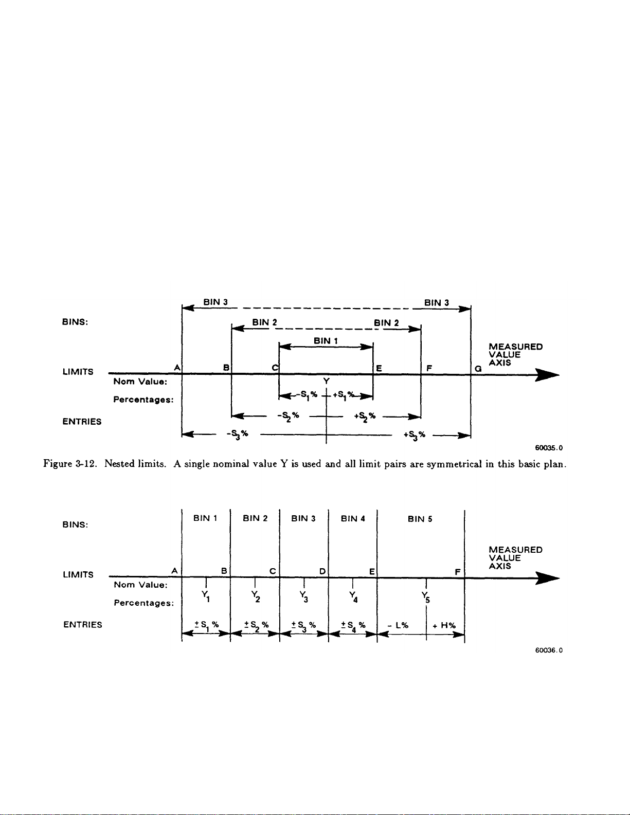
The test frequency can be selected after limits are entered, before any particular measurement.
3-50 OPERATION
3.8.2 Sorting Methods Figures 3-12, 3-13.
The figures illustrate 2 basic methods of sorting: nested and sequential. Nested limits are the natural choice for
sorting by tolerance around a single nominal value. The lower numbered bins must be narrower than the higher numbered ones.
Symmetrical limit pairs are shown; but unsymmetrical ones are possible. (For example, range AB could be assigned to bin 3
and range FG to bin 4 by use of unsymmetrical limit pairs in these bins.)
Sequential limits, on the other hand, are the natural choice for sorting by nominal value. Any overlap is assigned to
the lower numbered bin; any gap between bins defaults to bin 14. The usual method of entry uses a redefined nominal value for
each bin, with a symmetrical pair of limits. If it is necessary to define bins without overlap or gaps, use a single nominal value
and unsymmetrical limit pairs. It is possible to set up one or more tighter-tolerance bins within each member of a sequence.
Figure 3-13. Sequential limits. A different nominal value is entered for each bin and all limit pairs are symmetrical except for
the unsymmetrical pair shown for example in bin 5.
limits. However, there is no requirement that the bins be adjacent. Any of them can be defined with its own specific limits,
which may be overlapping, adjacent, or isolated from any other bin.
Bucket sorting means sorting into bins that are not nested. The usual method is that mentioned above, sequential
Page 99

3.8.3 Limit Entry Procedure
OPERATION 3-51
To enable comparisons (unless the keyboard is locked), first enter limits as follows. This procedure
makes use of limit entry keys, (at the left of the [SHIFT] key), with gray (or yellow) labels that apply only when the selected FUNCTION
is ENTER.
a. Press [DISPLAY] key to select VALUE.
Press [FUNCTION] key to select ENTER.
b. To enter a single QDR limit (always bin 0): press the parameter key (such as [Cs/D]) appropriate to DUT. To change range
and unit multipliers, press the same key repeatedly. (Refer to paragraph 3.3.4 for a table of units and multipliers, which indicates the
sequence of multipliers that will appear.) Enter the maximum limit of D or Rs or Q with R; enter the minimum limit of Rp or Q with L, as
follows. (Keyed numbers appear on the lefthand display). For example, to enter a Q limit of 85, press:
[8] [5] [=] [SHIFT] [BIN NO][0][0].
The value now moves to the right-hand display, confirming storage of the limit. Note: if you make a mistake,
press the parameter key again and repeat the entry.
c. To enter RLC limits for bins 1-13, three methods are given:
1. Symmetrical percentage tolerances (nested bins). Enter the nominal value of DUTs to be sorted.
(The value appears on the RLC display. Units were selected in step b.) For example, to enter 123.40 as the nominal value, press:
[1] [2][3] [.][4][=] [SHIFT] [NOM VAL].
Enter for bin 1 the narrowest percent tolerance to be sorted. As an example, for a tolerance of +/-0.2%: press
[.][2][%] [=][SHIFT] [BIN NO][0][l].
The numerical limits for RLC are automatically computed and rounded-off values appear on the Digibridge
displays (upper limit at the left, lower at the right).
For bin 2, enter the next wider tolerance, similarly. (Be sure to use 2 digits for the bin number.) Repeat the procedure for bins
3, 4, 5, ...up to a maximum of 13 bins.
2. Various nominal values (bucket sort). Plan for non-overlapping bins, each with a nominal value and limits defined by
percent t;olerance. For bin 1, enter nominal value and tolerance as described above. For each successive bin, similarly enter a new nominal
value, then the tolerance and bin number. (Changing the nominal value does not affect limits already stored. Any DUT that qualifies for 2
overlapping bins will automatically be assigned to the lower bin.)
3. Unsymmetrical tolerances. To enter unsymmetrical limits, for example +2% -5% in bin 6: press:
[2][%][-][S][%][=j[SHIFT][BIN NO] [0][6].
Two percentages of the same sign can be entered. Always enter the more positive tolerance first.
d. You can close any bin that has been opened (as in steps b, c). For RLC bins, follow this example for
bin 8: press:
Page 100

[0] [=] [SHIFT] [BIN NO] [0] [8].
3-52 OPERATION
To disable QDR sorting, close bin 0 (using two digits for the bin number, as noted before); thus: for D or Rs or Q
with R, press:
[9][9][9] [9] [=][SHIFT][BIN NO] [0][0];
However, for Rp or Q with L, press:
[0][=][SHIFT] [BIN NO] [0][0].
e. To enable GO/NO-GO lights after opening at least one bin, leave "nominal value" at any non-zero
value. To disable GO/NO-GO and all bin sorting, press:
[0] [=] [SHIFT] [NOM VAL].
Note: To see the present numerical limits for bin 3 (for example), press:
[SHIFT] [BIN NO] [0][3]
and similarly, to see the nominal value, press:
[SHIFT] [NOM VAL].
This is the value that the Digibridge will use for a subsequent entry of bin limits, and (when function is changed to
MEASURE and measurements are made) for calculation of delta %, delta RLC, etc.
For continued operation of the Digibridge, in MEASURE function, using the limits entered as above, you can select any
desired display, such as VALUE, or BIN No., with the [DISPLAY] key. (If you have the interface option, the available output data are
not limited to the display selection.) The GO/NO-GO lights will operate unless you inhibit comparisons. (See below.)
3.8.4 Verification or Nominal and Limit Values
While the function is ENTER, the exact values entered into the Digibridge can be seen by either of 2
methods, as follows.
During the Entry Process. A confirming display is automatically provided immediately after the final keystroke of each entry
step. For example, after the [NOM VALUE] keystroke, the entered value appears on the
RLC display. After the [BIN NO] and number keystrokes, the actual limits of RLC value (not percentages) appear across the full display
area: upper limit on the regular RLC display, lower limit (4 most significant digits) in the regular QDR display area. For bin 0, the QDR
limit appears in the QDR area.
 Loading...