

Page 1

DOC-QSG-XL4-RTU
DATRAN XL4 RTU
Quick Start Guide
Page 2
DATRAN XL4 RTU – Quick Start Guide – v1 – May 2012
Configuring the XL4
The XL4 is configured using software called “QTech Workbench”. Connection to your PC
is via a USB cable (Type A to Type B). The configuration software is available for
download from the QTech Website.
RTU Address
Every RTU has a unique site address so that a DATRAN base station can communicate
with it. When an RTU is installed at site, its address must be configured. Unlike older
model DATRAN RTUs, the address for the XL4 is configured using QTech Workbench.
The module address can be any number between 1 and 239.
Factory Defaults
From time to time it may be necessary for you to reset the XL4 back to factory defaults.
There are two ways of doing this.
1) There is a jumper on the XL4 main processor board labelled “INIT”. It is normally
open, but if the RTU is started up while the jumper is installed it will cause the RTU
to restore the factory default settings.
2) The factory default settings can also be loaded back into the RTU using the ‘Factory
Default’ button at the bottom of the QTech Workbench screen.
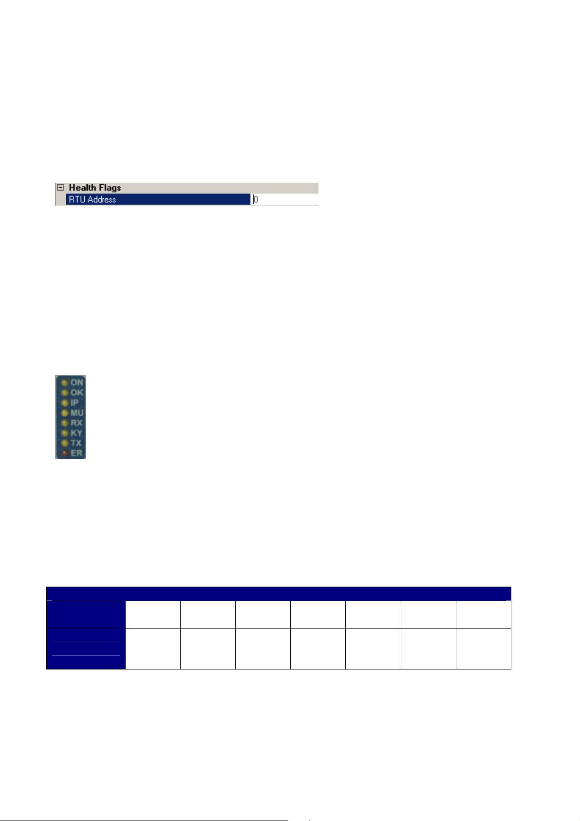
Status LEDs
ON: This LED is always on when the XL4 RTU is powered.
OK : This LED flashes on a 1 second cycle to show the CPU has not locked up.
If it is on solidly or stays off, then the XL4 RTU needs attention.
IP : This LED indicates that the XL4 RTU is currently sending comms out its
IPB port to communicate with I/O expansion modules.
MU : The MUTE signal from the Radio. This indicates the radio is currently
receiving an RF signal.
RX : The RTU modem is receiving and decoding data from the radio. This LED
will usually appear to “flicker”
KY : This indicates the RTU is attempting to key on the radio transmitter.
TX : The RTU is transmitting data through the radio. This LED will usually
appear to “flicker”
ER : This is the Error Indication LED. The LED will flash a certain number of
times to indicate any error messages the XL4 RTU has been configured to
display.
XL4 Error Messages
Number of
Flashes
Message
1 2 3 4 5 6 7
Main
Battery
Low
Clock
Battery
Low
Main
Comms
Fail
IPB
Comms
Fail
Digital
Outputs
Fail
Analog
Inputs
Fail
DLP
Error
Supply Voltage: 12 Volts or 24 Volts
The DATRAN XL4 RTU can be supplied from 12-30V DC. The RTU comes factory
configured for a nominal 12V DC supply, unless otherwise requested. When configured
for 12V, the RTU will automatically shut itself down when the supply voltage drops to
10.5V.
Page 3

DATRAN XL4 RTU – Quick Start Guide – v1 – May 2012
can damage the socket.
If the RTU is to be supplied from 24V it is necessary to
change J27, located on the Q22 (bottom board) in the
RTU. This changes the low voltage shutdown voltage to
21V.
Low Voltage Drop Out
Threshold
J27
12V supply Installed
24V supply Open
Power Supply Connections
The XL4 power connector has three connections:
-V = Power Supply Negative
+V = Power Supply Positive, 12 – 30 V DC
O/P = Control Signal Output. This allows the RTU to turn on devices when it
is powered up. This was previously labelled “C” on eXcel RTUs
The “O/P” terminal is an OUTPUT. Do not connect it to the supply.
The XL4 and associated peripherals should all share a common earth point.
RS485 Port
The XL4 RS485 port is an RJ12 connector, identified by having 6 contacts,
as shown. The previous Q03 RS485 connectors were an RJ10 connector
with 4 contacts. Ensure that the 6 contact RJ12 is plugged into the XL4
RTU. Do not attempt to insert the 4 contact RJ10 into the RTU, this must be
inserted in the expansion module (Q23/Q26 etc).
The connector used for the XL4 RS485 port looks similar to the one used
on the Q03. Care must be taken as forcing a Q03 RJ10 plug into a Q04
Digital Inputs
The RTU digital inputs are designed to interface easily with physical switching devices.
They have an internal pull-up resistor that will pull the input
terminal to the power supply ‘+’ when the input is open circuit
(the “OFF” state).
To turn a digital input ON, connect it (via a set of contacts if
necessary) to the common “G” terminal on the Digital Input
terminal block. All “G” terminals on the XL4 RTU are tied
internally to the “G” terminal on the power supply connector.
The LED associated with each digital input will light up when the input is Active/On/Closed.
The pull up / pull down convention is different from some PLCs. If required, the
active state of I/O can be inverted in the XL4 RTU DLP control program or PLC
Page 4

DATRAN XL4 RTU – Quick Start Guide – v1 – May 2012
Digital Outputs
The XL4 RTU Digital Outputs are designed to be easily interfaced with relays and
contactors.
The XL4 RTU has 8 Digital Outputs in total. Digital Outputs 1 to 4 are located on the front
panel adjacent to the Digital Inputs and have LED indicators to show if the output is active
or not. Digital Outputs 5 to 8 are located on the underside of
the RTU next to the power connector.
The Digital Outputs work as “Current Sinks”. This means
that when they are turned on, they will be connected to
power supply ground, allowing current to flow into the output
terminal to ground. In the “OFF” state, they have a high
impedance to ground and will float up to + Supply.
To use a digital output with a relay, wire as shown in the diagram opposite:
Analog Inputs
The XL4 RTU has 6 analog channels. All analog channels are independently capable of
operation as either 0-20mA, 4-20mA, 0-5V or 0-10V. In addition to this, channels 5 and 6
are independently able to be configured as either inputs or outputs. The XL4 RTU is
factory shipped with all analog channels configured as 4-20 mA inputs. For details on how
to reconfigure them, refer to the Owners Manual.
For all analog inputs, the current return path is via the ground of the XL4 RTU power
supply. It is important to understand the implications of this when wiring certain analog
devices to the RTU, as detailed below.
The LEDs adjacent to each Analog Input show the status of the signal the XL4 RTU is
receiving. If the LED is off, it means the input signal is zero, or under-range. When the
LED is on, it indicates the signal is within the measuring range that the input has been
configured for. If the LED is flashing, it shows the signal is over-range.
Loop Powered Devices
“Loop-Powered”, or “2-Wire” devices derive their power supply from the current flowing in
the loop itself. It is important to make sure that any device is rated to operate at the voltage
that will be available to it taking into account that the XL4 RTU Analog Input will drop 5V
across it at 20mA loop current.
For example: If the system is being powered from 13.7V
DC, the analog transducer will only have a maximum of
8.7V available to it for its power supply.
To wire a “2-Wire” device, refer to the diagram opposite:
Separately Supplied Devices
“Separately Supplied”, or “4-Wire” devices are analog
transmitters that have a separate power supply from the
analog signal loop. If suitable, these devices can be
powered from the XL4 RTU power supply. If the XL4
RTU power supply is not suitable, the analog sensor can be powered from a separate
power supply as long as the grounds of both the XL4 RTU and the other power supply are
connected together.
Wiring of a 4-Wire device is as shown:
 Loading...