

Page 1
Weatherized WideLine Series
User Manual
WL2102-wx Loudspeaker
WL3082-wx Loudspeaker
GP218-wx Subwoofer
TD-000307-00 Rev. A
*TD-000307-00*
Page 2

2
IMPORTANT SAFETY PRECAUTIONS AND EXPLANATION OF SYMBOLS
WARNING!
The lightning flash with the arrowhead symbol within an equilateral triangle is intended to alert the user to the presence of
uninsulated “dangerous” voltage within the product’s enclosure that may be of sufficient magnitude to constitute a risk of
shock to humans.
The exclamation point within an equilateral triangle is intended to alert the user to the presence of important operation and
maintenance (servicing) instructions in this manual.
1. Read these instructions.
2. Keep these instructions.
3. Heed all warnings.
4. Follow all instructions.
5. Clean only with a dry cloth.
6. Install in accordance with QSC Audio Product’s instructions and local building codes. The installation should be done by a licensed
installation professional.
7. Do not install near any heat sources such as radiators, heat registers, stoves, or other apparatus (including amplifiers) that produce heat.
8. Only use attachments/accessories from QSC Audio Products, LLC.
9. Use only with mounts or brackets supplied or specified by QSC Audio Products, LLC.
10. Refer all servicing to qualified personnel. Servicing is required when the apparatus has been damaged in any way.
WARNING! Before placing, installing, rigging, or suspending any speaker product, inspect all hardware, suspension, cabinets,
transducers, brackets and associated equipment for damage. Any missing, corroded, deformed or non-load rated component
could significantly reduce the strength of the installation, placement, or array. Any such condition severely reduces the safety of the
installation and should be immediately corrected. Use only hardware which is rated for the loading conditions of the installation
and any possible short-term unexpected overloading. Never exceed the rating of the hardware or equipment. Consult a licensed,
professional engineer when any doubt or questions arise regarding a physical equipment installation.
Warranty (USA only; other countries, see your dealer or distributor)
Disclaimer
QSC Audio Products, LLC is not liable for any damage to amplifiers, or any other equipment that is caused by negligence or improper installation and/
or use of this loudspeaker product.
QSC Audio Products 3-Year Limited Warranty
QSC Audio Products, LLC (“QSC”) guarantees its products to be free from defective material and / or workmanship for a period of three (3) years from
date of sale, and will replace defective parts and repair malfunctioning products under this warranty when the defect occurs under normal installation
and use - provided the unit is returned to our factory or one of our authorized service stations via prepaid transportation with a copy of proof of
purchase (i.e., sales receipt). This warranty provides that the examination of the return product must indicate, in our judgment, a manufacturing defect.
This warranty does not extend to any product which has been subjected to misuse, neglect, accident, improper installation, or where the date code has
been removed or defaced. QSC shall not be liable for incidental and/or consequential damages. This warranty gives you specific legal rights. This limited
warranty is freely transferable during the term of the warranty period. Customer may have additional rights, which vary from state to state.
In the event that this product was manufactured for export and sale outside of the United States or its territories, then this limited warranty shall not apply.
Removal of the serial number on this product, or purchase of this product from an unauthorized dealer, will void this limited warranty.
Periodically, this warranty is updated. To obtain the most recent version of QSC’s warranty statement, please visit www.qscaudio.com.
Contact us at 800-854-4079 or visit our web site at www.qscaudio.com.
© Copyright 2010, QSC Audio Products, LLC
QSC is a registered trademark of QSC Audio Products, LLC
“QSC” and the QSC logo are registered with the U.S. Patent and Trademark Office
All trademarks are the property of their respective owners.
1
Page 3

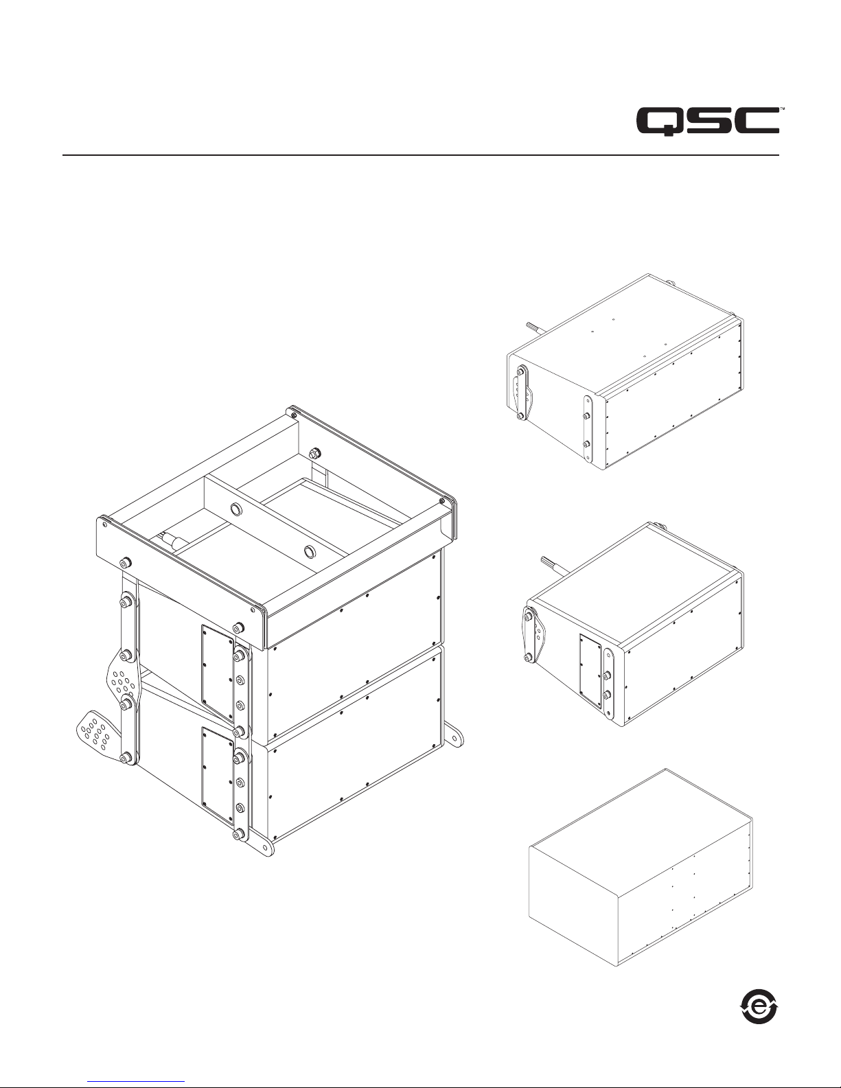
Package Contents
WL2102-wx / WL3082-wx Loudspeakers
Front Outer Rigging Link - WL3082-wx (10.5 in., 267 mm) (P/N CH-000980-00)
Front Outer Rigging Link - WL2102-wx (8.6 in., 219 mm) (P/N CH-000987-00)
Front Center Front Rigging Link (P/N CH-000981-00) 2
M10 Flat Washer 4
M10 Lock Washer 4
Nylon Spacer 4
M10 Hex Socket Cap Screw, 70L - WL3082-wx
M10 Hex Socket Cap Screw, 50L - WL2102-wx
Owners Manual 1
GP218-wx Subwoofer
Owners Manual 1
AF3082-wx Array Frame (assembly only)
AF2102-wx Array Frame (assembly only)
2
2
4
4
Features
WL3082-wx Loudspeaker
a. Suspension Attachment Screws (Qty: 8)
b. Suspension Links
c. Port Grille
d. Grille
e. Splay Angle Selector holes
f. 25" Cable
e
ca
d
– Figure 1 –
b
– Figure 2 –
f
2
Page 4

4
WL2102-wx Loudspeaker
a. Suspension Attachment Screws (Qty: 8)
b. Suspension Links
c. Grille
d. Splay Angle Selector holes
e. 25" Cable
a
d
– Figure 3 –
c
b
e
– Figure 4 –
GP218-wx Loudspeaker
a. Grille
b. Non-Slip Feet
c. 25" Cable
– Figure 5 – – Figure 6 –
c
a
b
3
Page 5

AF3082-wx and AF2102-wx Array Frames
a. Shackle Holes (accept 5/8" (16 mm) screw pin anchor shack)
b. Center Support Bar
c. Suspension Plate
d. Rigging Links
e. Suspension Attachment Screws
d
a
e
– Figure 7 –
Suspending the Weatherized WideLines
Rules for Suspension
• Correct use of all suspension hardware and components is imperative in sound system suspension and deployment.
c
b
• Always calculate suspended loads before lifting to ensure suspension components and hardware are used within their respective load limits.
• Research local codes and regulations to fully understand the requirements for suspended loads in the venue in which the equipment is to
be suspended.
• Use only shackle holes for suspension of array.
• Be absolutely certain of the integrity of any structural member intended to support suspended loads. Hidden structural members can have
hidden structural weakness.
• Consult a Professional Mechanical or Structural Engineer licensed in the jurisdiction of the sound system installation to review, verify, and
approve all attachments to the building or structure.
• Never assume anything. Owner or third-party supplied suspension attachment points may not be adequate for the loads to be suspended.
• Employ the services of a Professional Rigger for hoisting, positioning, and attaching the equipment to the supporting structure.
• Always inspect all components (enclosures, suspension brackets, pins, frames, bolts, nuts, slings, shackles, etc.) for cracks, wear,
deformation, corrosion, missing, loose, or damaged parts that could reduce the strength of the assembly before lifting. Discard any worn,
defective, or suspect parts and replace them with new appropriately load-rated parts.
• This product is designed to use outside. When suspending, be sure to take into account all possible weather conditions, such as wind, for
the local area in which the product is installed.
Shock Loading
When a load is either moved or stopped, its static weight is magnified. Sudden movements can magnify the static weight several times. This
magnification of static weight is termed "shock loading". Shock loading poses a danger to equipment and workers. The effects of shock loading can
be instantaneous, or they may remain undetected unless the equipment is visually damaged. Avoiding shock loading requires careful planning and
knowledge of equipment, suspension, and lifting practices. Shock loading of equipment and structures is usually confined to lifting and installation, but
natural forces (winds, earthquakes) can impose shock loads several times the static load. This is why structures and suspension equipment must be
capable of supporting several times the weight of the equipment suspended.
4
Page 6

6
Weatherized WideLine Working Load Limits and Design Factors
(Table 1) lists the suspension components and provides Working Load Limit data at various Design Factors. The tabulated Design Factors are for
static loads only. The choice of which Design Factor to use will depend upon the jurisdiction and venue of installation, as well as the conditions of
suspension. Dynamic conditions are determined by unknown, installation-specific factors and should be referred to a Licensed Structural Engineer for
clarification before proceeding with any suspension of the equipment. The data presented is based upon the listed component weights.
Component Weight 7:1 Design Factor 10:1 Design Factor 12:1 Design Factor
AF3082-wx 11.0 lbs. (5.0 kg) 746 lbs. (338.3 kg) 12 boxes 522 lbs. (236.8 kg) 8 boxes 435 lbs. (197.3 kg) 7 boxes
AF2102-wx 12.5 lbs. (5.7 kg) 514 lbs. (233.1 kg) 5 boxes 360 lbs. (163.3 kg) 3 boxes 300 lbs. (136.1 kg) 3 boxes
– Table 1 –
Suspending the Weatherized Wideline
The WL3082-wx and WL2102-wx are suspended below the AF3082-wx and AF2102-wx Array Frames respectively. The procedures are the same for
each model. The parts necessary for suspension are packaged with the individual loudspeakers. If you are working with both models, be sure to keep
the parts separate. For each model, there are two different length screws, the screw length for the WL2102-wx is shown in parenthesis.
Bottom Loudspeaker in the Array
1. Start with the bottom loudspeaker assembly on a flat, stable surface, remove the four bolts, associated washers, and hardware from both rear
corners as shown. Place aside for later use.
Note: You can add an Array Frame to the bottom Loudspeaker if needed. Refer to the Assembling the Array Frame section in this document.
Disassembly
a. M10 Hex Socket Cap Screw
b. M10 Lock Washer
c. M10 Flat Washer
d. Rear Suspension Link
e. Rear-center Suspension Link
a
b
c
d
e
– Figure 8 –
5
Page 7
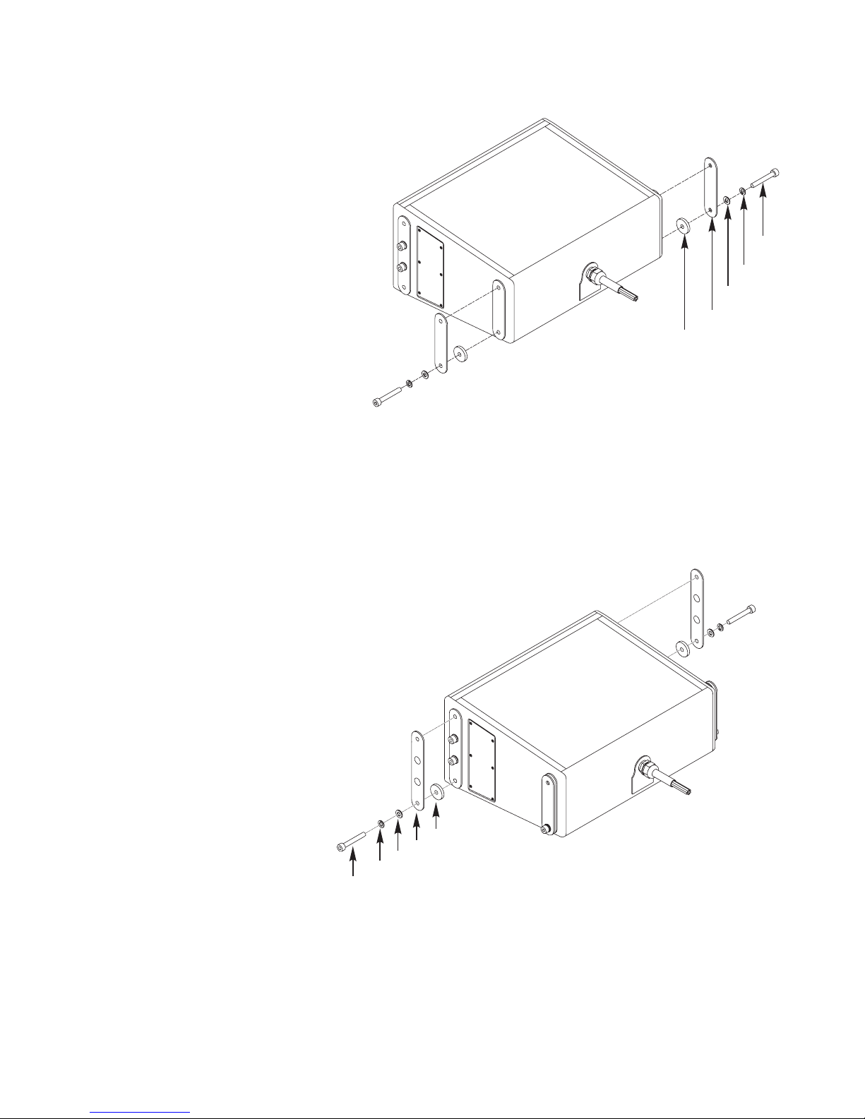
2. Install the hardware listed below onto both rear corners of the loudspeaker as shown in (Figure 9). Hand-tighten only at this time.
Assembly Order
a. Nylon Spacer
b. Rear Suspension Link (removed earlier)
c. M10 Flat Washer (removed earlier)
d. M10 Lock Washer (removed earlier)
e. M10 Hex Socket Cap Screw (removed earlier)
b
a
– Figure 9 –
e
d
c
3. Attach the external rigging straps and associated hardware (packaged separately) as shown below.
Assembly Order
a. Nylon Spacer (new)
b. Front-outer Rigging Link (new)
(
WL3082-wx P/N CH-000980-00)
(WL2102-wx P/N CH-000987-00)
c. M10 Lock Washer (new)
d. M10 Flat Washer (new)
e. M10 Hex Socket Cap Screw 70L (50L) (new)
a
b
c
d
e
– Figure 9 –
6
Page 8

8
Top or Middle Loudspeaker in the Array
1. Place the next loudspeaker assembly on a flat, stable surface, remove the two cap screws, flat washers, and lock washers from both top-rear
corners as shown. Place aside for later use.
2. Loosen the two bottom-rear cap screws and rotate the rear-center rigging link 90° so that it is pointing down as shown. Hand-tighten the
cap screws.
Disassembly
a. M10 Hex Socket Cap Screw
b. M10 Flat Washer
c. M10 Lock Washer
Loosen only
c
b
a
– Figure 10 –
3. Attach two Front-center Rigging Links and two Front-outer Rigging Links with four Lock Washers, four Flat Washers and four Cap Screws as shown
below. (These parts are in a separate package in the loudspeaker shipping box.)
Assembly Order
a. Front-center Rigging Link (new)
b. Front-outer Rigging Link (new)
c. M10 Lock Washer (new)
d. M10 Flat Washer (new)
e. M10 Hex Socket Cap Screw 70L (50L) (new)
a
b
c
d
e
– Figure 11 –
7
Page 9
Assembling the Array
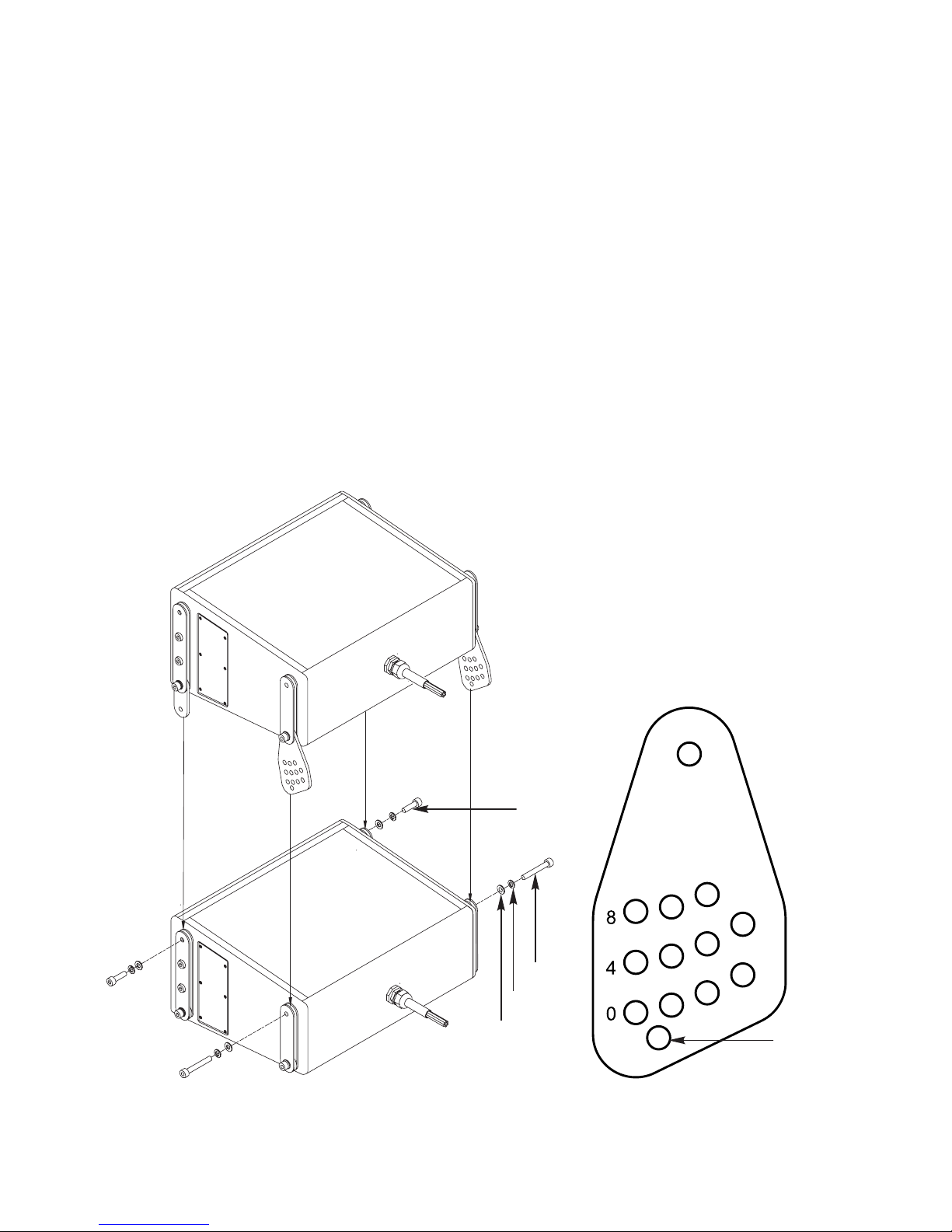
1. Place the pre-assembled top or middle loudspeaker assembly on top of the bottom (or another middle) loudspeaker, aligning the rigging links with
their respective rigging links on the bottom loudspeaker as shown below.
2. Secure the top loudspeaker to the bottom loudspeaker with two L70 cap screws in the rear, and two L70 (L50) cap screws in the front. Torque all
cap screws to 60 in.-lbs.
Note: Each hole on the Rear-center Rigging Link represents 1 degree of angle for setting the splay. The rows are numbered 0, 4, and 8, indicating holes
0 - 10. Use QSC's EASE Focus to determine the proper angles.
You can download EASE Focus at (http://www.qscaudio.com/products/software/EASE_Focus/ease_focus.htm).
Assembly order
a. M10 Lock Washer (front new, rear removed earlier)
b. M10 Flat Washer (front new, rear removed earlier)
c. M10 Hex Socket Cap Screw (rear - removed earlier)
d. M10 Hex Socket Cap Screw 70L (50L) (new)
– Figure 12 –
d
c
b
a
Used for shipping
only.
– Figure 13 –
8
Page 10

10
Assembling the Array Frame
1. Place the Array Frame on top of the top loudspeaker, aligning the rigging links with their respective rigging links on the top loudspeaker as
shown below.
2. Secure the Array Frame to the top loudspeaker with two 70L / 50L cap screws in the rear, and two 70L / 50L cap screws in the front. Torque all cap
screws to 60 in.-lbs.
Assembly Order
a. Array Frame
b. M10 Lock Washer (front new, rear removed earlier)
c. M10 Flat Washer (front new, rear removed earlier)
d. M10 Hex Socket Cap Screw (rear removed earlier)
e. M10 Hex Socket Cap Screw 70L (50L) (front new)
Weatherized WideLine Wiring Configuration
– Figure 12 –
a
e
d
c
b
WL3082-wx / WL2102-wx Loudspeakers
(6-conductor, 14 awg, SOOW cable)
+ -
HF Orange Blue
MF Red Green
LF Black White
GP218-wx Subwoofer
(4-conductor, 14 awg, SOOW cable)
+ -
Sub1 Red Green
Sub2 Black White
9
Page 11

Specifications
WL3082-wx WL2102-wx GP218-wx
Configuration Tri-amp only line-array Tri-amp only line-array Subwoofer
Transducers HF: 1.4" exit, 3" diaphragm, neodymium
magnet compression driver
LF: Dual, 8" woofer, 2.5" voice coil
Nominal Impedance HF: 16 ohms
MF: 16 ohms
LF: 16 ohms
Frequency Response (-6 dB)
Frequency Range (-10 dB)
1
1
68 Hz - 18 kHz 55 Hz - 18 kHz 31 Hz - 100 Hz
62 Hz - 20 kHz 48 Hz - 20 kHz 27 Hz - 120 kHz
Continuous Power Capacity 1 HF: 85 W
MF: 250 W
LF: 250 W
Sensitivity (1 W at 1 m) HF: 108 dB SPL
MF: 98 dB SPL
LF: 98 dB SPL
Maximum Output, Continuous / Peak
(dB SPL at 1 m)
HF: 127 dB SPL / 133 dB SPL
MF: 122 dB SPL / 128 dB SPL
LF: 122 dB SPL / 128 dB SPL
Nominal Coverage H: 140°
V: dependent on number of
elements used
Enclosure Type Ported, trapezoidal Vented, rectangular enclosure
Enclosure Material Baltic birch plywood coated with laid-up fiberglass and light grey gelcoat.
Grille Perforated, powder-coated stainless steel, backed with foam and stainless steel mesh screen
IP Rating IP56 (per IEC529 Also tested to MIL-STD-810E
Connectors Tinned, bare wire
Attachment Points Included, adjustable rigging system, vertical splay adjustable in 1° increments
from 0° - 10°
Weight (Net) 61 lbs. (27.7 kg) 92.5 lbs. (42.0 kg) 215 lbs. (97.5 kg)
Dimensions (HWD) 9.5" x 20" x 15.5"
241 mm x 508 mm x 394 mm
Available Accessories AF3082-wx aluminum array frame AF2102-wx aluminum array frame None
HF: 1.4" exit, 3" titanium diaphragm,
neodymium magnet assembly
LF: Dual, 10" woofer, 3" voice coil
HF: 16 ohms
MF: 16 ohms
LF: 16 ohms
HF: 85 W
MF: 400 W
LF: 400 W
HF: 107.5 dB (Single cabinet measured
in free space.)
LF: 98 dB (Single cabinet measured
in free space. LF drivers connected
in parallel.)
HF: 127 dB SPL / 133 dB SPL
LF: 127 dB SPL / 133 dB SPL
H: 140°
V: dependent on number of
elements used
11.75" x 27.25" x 18.5"
298 mm x 692 mm x 470 mm
HF: N/A
LF: Dual 18" vented subwoofer
4 ohms
2
2
1700 W
101.5 dB
130.5 dB / 140.5 dB
N/A
None
(M10 points available by request)
21.1" x 30.1" x 47.3"
537 mm x 765 mm x 1202 mm
1) With recommended processing.
2) Recommended operating range.
Specifications subject to change without notice.
10
Page 12

12
Dimensions
WL3082-wx Loudspeaker
15.5"
397 mm
20"
508 mm
9.5"
241.3 mm
11
Page 13

WL2102-wx Loudspeaker
27.25"
692 mm
18.5"
469.9 mm
11.75"
298.5 mm
12
Page 14

14
GP218-wx Subwoofer
47.32"
1201.8 mm
30"
765 mm
22.0"
560 mm
13
Page 15

AF3082-wx Array Frame
8.0"
203 mm
21.1"
536 mm
18.1"
459 mm
3.8"
95 mm
7.06"
179.4 mm
14
Page 16

Mailing Address:
QSC Audio Products, LLC
1675 MacArthur Boulevard
Costa Mesa, CA 92626-1468 USA
Telephone Numbers:
Main Number: (714) 754-6175
Sales & Marketing: (714) 957-7100 or toll free (USA only) (800) 854-4079
Customer Service: (714) 957-7150 or toll free (USA only) (800) 772-2834
Facsimile Numbers:
Sales & Marketing FAX: (714) 754-6174
Customer Service FAX: (714) 754-6173
World Wide Web:
www.qscaudio.com
E-mail:
info@qscaudio.com
service@qscaudio.com
© 2010 QSC Audio Products, LLC. All rights reserved. QSC and the QSC logo are registered trademarks of QSC Audio Products, LLC in the U.S. Patent and Trademark office and other countries.
Speakon is a trademark of Neutrik. All other trademarks are the property of their respective owners. Patents may apply or be pending.
 Loading...