

Page 1
K Series
User Manual
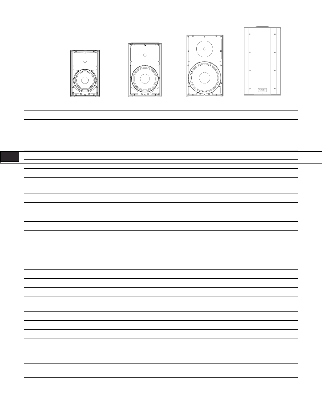
K8 – 105° 1000 W active 8" (200 mm) 2-way loudspeaker system
K10 – 90° 1000 W active 10" (250 mm) 2-way loudspeaker system
K12 – 75° 1000 W active 12" (300 mm) 2-way loudspeaker system
KSub – Dual 12" (300 mm) 1000 W active 4th-order bandpass subwoofer system
TD-000280-00-D
*TD-000280-00*
Page 2
IMPORTANT SAFETY PRECAUTIONS AND EXPLANATION OF SYMBOLS
WARNING!
CAUTION: TO REDUCE THE RISK OF ELECTRIC SHOCK, DO NOT REMOVE THE AMPLIFIER
COVER. NO USER-SERVICEABLE PARTS INSIDE. REFER SERVICING TO QUALIFIED PERSONNEL.
The lightning flash with the arrowhead symbol within an equilateral triangle is intended to alert the user to the presence of uninsulated “dangerous” voltage within the product’s enclosure that may be of sufficient magnitude to constitute a risk of shock to humans.
The exclamation point within an equilateral triangle is intended to alert the user to the presence of important operation and
maintenance (servicing) instructions in this manual.
1. Read these instructions.
2. Keep these instructions.
ENG ENG
3. Heed all warnings.
4. Follow all instructions.
5. WARNING: To prevent fire or electric shock, do not expose this equipment to rain or moisture. Do not use this apparatus near water.
6. Clean only with a dry cloth.
7. Allow a minimum of 6" (152 mm) clearance behind cabinet for convection cooling. Keep anything that might restrict airflow from the rear of the
enclosure (i.e. draperies, fabric, etc.). Do not block any ventilation opening. This product contains an internal power amplifier that produces heat.
8. Do not install near any heat sources such as radiators, heat registers, stoves, or other apparatus (including amplifiers) that produce heat.
9. Do not defeat the safety purpose of the grounding-type plug on the three-pronged “Edison” style power cable. The grounding plug has two blades
and a grounding prong. The third prong is provided for your safety. If the provided plug does not fit your outlet, consult an electrician for the
replacement of the obsolete outlet. Do not cut off the grounding plug or use an adapter that breaks the grounding circuit. This apparatus must be
properly grounded for your safety.
10. Protect the power cord from being walked on or pinched, particularly plugs, convenience receptacles, and the point where they exit from
the apparatus.
11. The appliance coupler is the AC mains disconnect and should remain readily operable after installation.
12. Use only attachments/accessories specified by QSC Audio Products, LLC.
13. Use only with hardware, brackets, and components sold with the apparatus or by QSC Audio Products, LLC.
14. Unplug the apparatus during lightning storms or when unused for long periods of time.
15. Refer all servicing to qualified service personnel. Servicing is required when the apparatus has been damaged in any way, such as power supply
cord or plug is damaged, liquid has been spilled or objects have fallen into the apparatus, the apparatus has been exposed to rain or moisture,
does not operate normally or has been dropped.
16. Before placing, installing, rigging or suspending any loudspeaker product, inspect all hardware, suspension, cabinets, transducers, brackets and
associated equipment for damage. Any missing, corroded, deformed, or non-load rated component could significantly reduce the strength of the
installation and should be immediately corrected. Use only hardware which is rated for the loading conditions of the installation and any possible
short-term unexpected overloading. Never exceed the rating of the hardware or equipment.
17. Consult a licensed, professional engineer when any doubt or questions arise regarding a physical equipment installation.
18. The appliance shall not be exposed to dripping or splashing and no objects filled with liquids, such as vases, shall be placed on the apparatus.
2
Page 3
Warranty (USA only; other countries, see your dealer or distributor)
QSC Audio Products 3 Year Limited Warranty
QSC Audio Products, LLC (“QSC”) guarantees its products to be free from defective material and/or workmanship for a period of three (3) years from
the date of sale and will replace defective parts and repair malfunctioning products under this warranty when the defect occurs under normal installation and use – provided the unit is returned to our factory or one of our authorized service stations via prepaid transportation with a copy of proof of
purchase (i.e., sales receipt). This warranty provides that the examination of the returned product must indicate, in our judgement, a manufacturing
defect. This warranty does not extend to any product which has been subjected to misuse, neglect, accident, improper installation, or where the date
code has been removed or defaced. QSC shall not be liable for incidental and/or consequential damages. This warranty gives you specific legal rights.
This limited warranty is freely transferable during the term of the warranty period.
Customer may have additional rights, which vary from state to state.
In the event that this product was manufactured for export and sale outside of the United States or its territories, then this limited warranty shall not
apply. Removal of the serial number on this product, or purchase of this product from an unauthorized dealer will void this limited warranty.
Periodically, this warranty is updated. To obtain the most recent version of QSC’s warranty statement, please visit www.qscaudio.com.
Contact us at 800-854-4079 or visit our website at www.qscaudio.com.
FCC Statement
NOTE: This equipment has been tested and found to comply with the limits for a Class B digital device, pursuant to Part 15 of the FCC Rules.
These limits are designed to provide reasonable protection against harmful interference in a residential installation. This equipment generates, uses
and can radiate radio frequency energy and, if not installed and used in accordance with the instructions, may cause harmful interference to radio
communications. However, there is no guarantee that interference will not occur in a particular installation. If this equipment does cause harmful
interference to radio or television reception, which can be determined by turning the equipment off and on, the user is encouraged to try to correct
the interference by one or more of the following measures:
• Reorient or relocate the receiving antenna.
• Increase the separation between the equipment and receiver.
• Connect the equipment into an outlet on a circuit different from that to which the receiver is connected.
• Consult the dealer or an experienced radio/TV technician for help.
Package Contents
K8, K10, K12
(1) Loudspeaker system
(1) Locking power cable
(1) Euro-style Connector Plug, 3-pin
(1) K Series Hookup Drawings
(1) Warning Information Sheet
KSub
(1) Subwoofer system
(1) Locking power cable
(1) Euro-style Connector Plug, 3-pin
(1) M20 threaded loudspeaker pole
(1) K Series Hookup Drawings
(1) Warning Information Sheet
3
Page 4
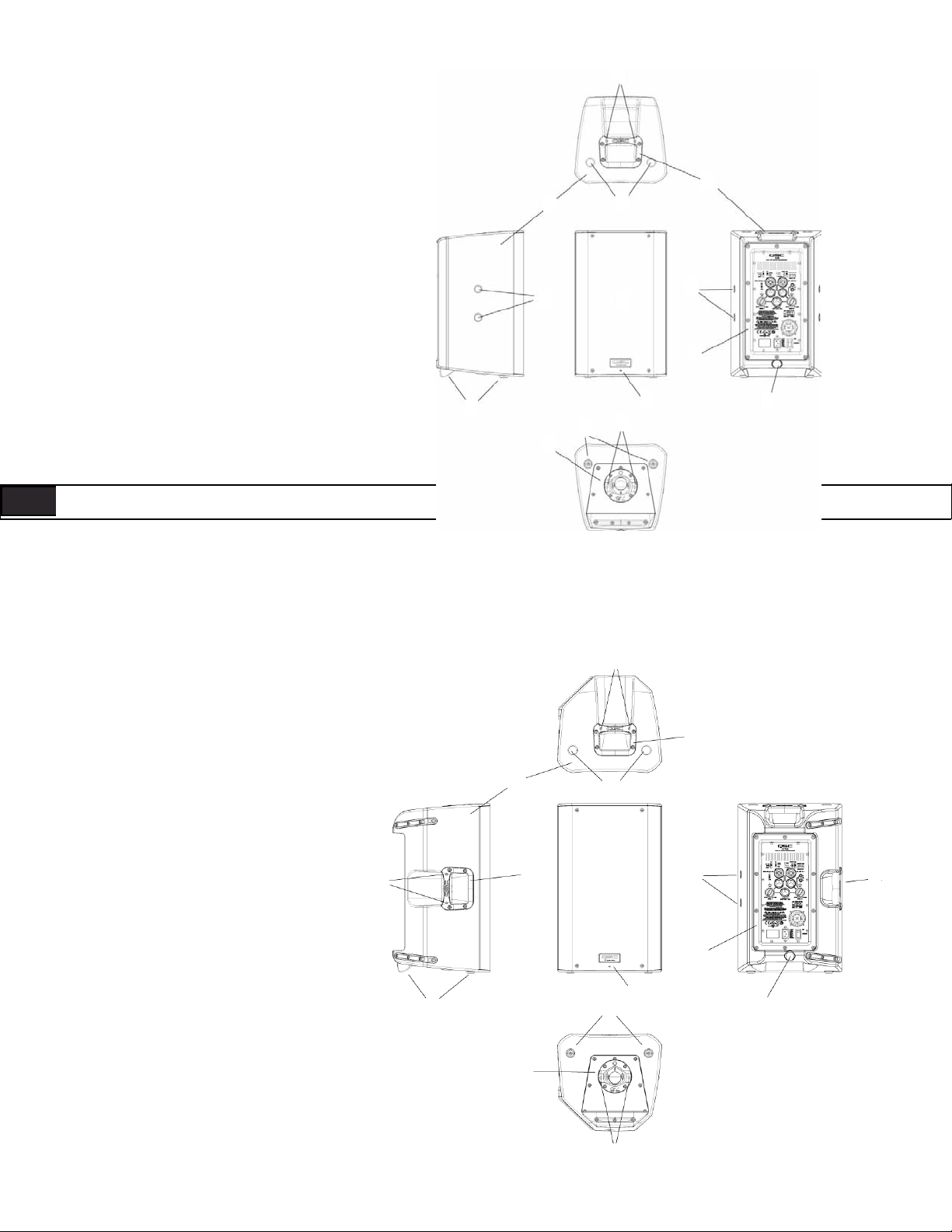
Features
K8
1. ABS enclosure
2. Steel grille
3. Front power LED
7
4
1
6
4. Cast aluminum handles
7
2
7
5. Power module
6. M10 installation points
5
7. M5 yoke attachment points
8. Tilt-Direct™ dual angle pole socket
9. Slip-resistant feet
9
9
8
3
7
6
ENG ENG
7
4
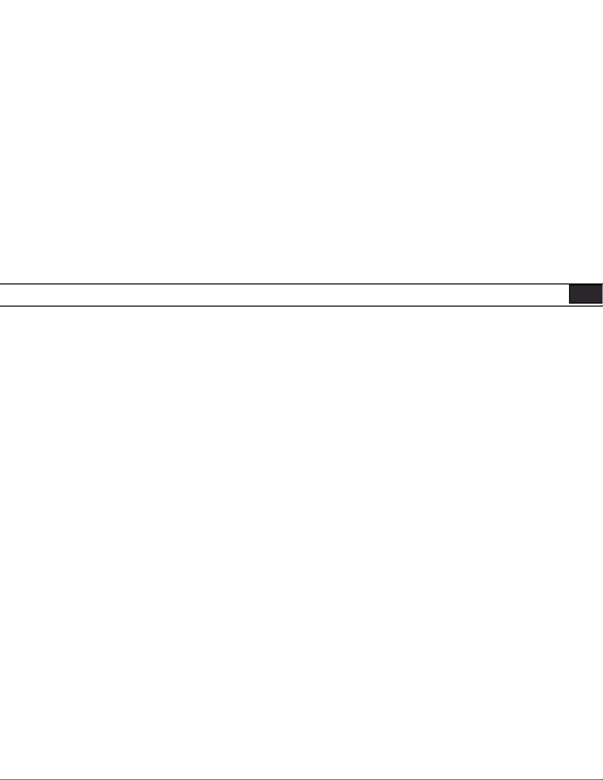
K10
1. ABS enclosure
2. Steel grille
3. Front power LED
4. Cast aluminum handles
5. Power module
6. M10 installation points
7. M5 yoke attachment points
8. Tilt-Direct™ dual angle pole socket
9. Slip-resistant feet
1
7
9
4
8
6
2
3
9
7
7
5
6
4
4
Page 5

7
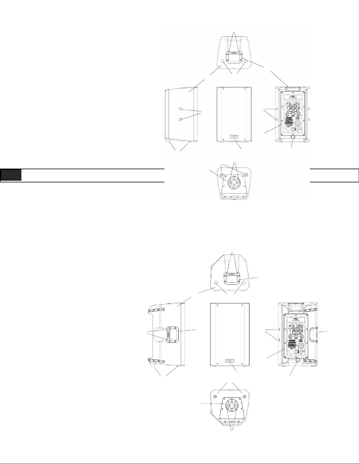
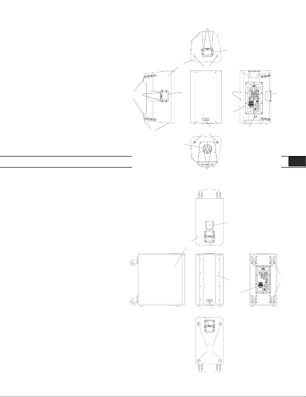
K12
1. ABS enclosure
2. Steel grille
3. Front power LED
4. Cast aluminum handles
5. Power module
6. M10 installation points
7. M5 yoke attachment points
8. Tilt-Direct™ dual angle pole socket
9. Slip-resistant feet
4
1
7
9
4
8
6
2
3
99
7
7
7
5
6
4
KSub
1. Birch plywood enclosure
2. Front power LED
3. Acoustic port
4. Cast aluminum handles
5. Power module
6. M20 threaded pole receptacle
7. 3" heavy duty casters
8. Slip-resistant feet
6
1
4
3
5
2
4
8
7
7
5
Page 6
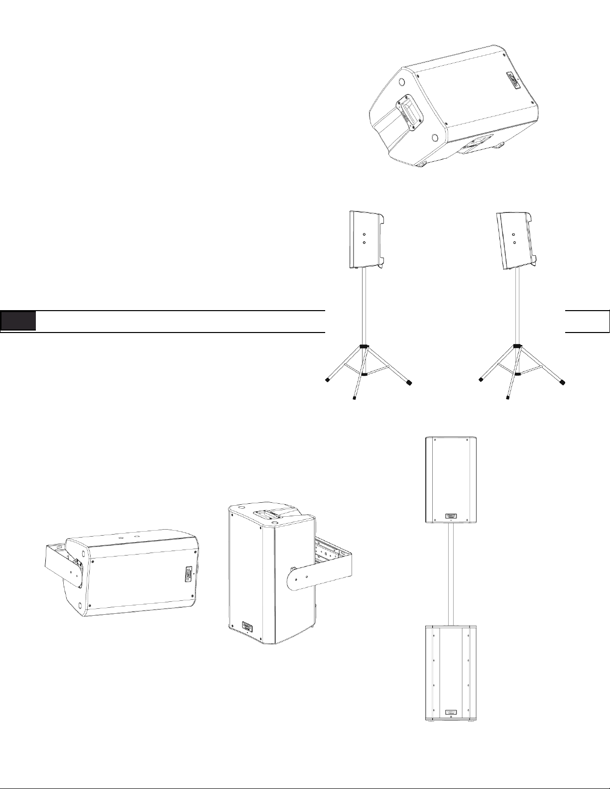
Applications
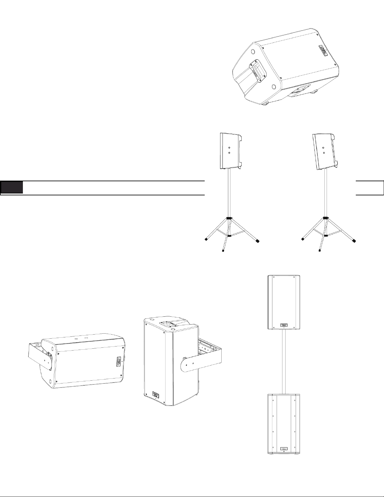
The K Series has been primarily designed for portable audio reinforcement. This includes a variety of uses in reinforcement for entertainers
and presenters. The K8, K10 and K12 are all designed to perform well on
their own in full-range audio. They can be used singly, in stereo pairs or
in distributed or delayed systems. They perform extraordinarily well as
both main reinforcement systems and as floor monitors (K10 and K12
only). (Figure 1)
The K8, K10, and K12 are all equipped with a 35 mm pole socket that
allows use on a speaker stand or on a pole over a subwoofer. The pole
socket features the QSC Tilt-Direct™ system for tilting the enclosures
down 7.5 degrees while on the pole. (Figure 2)
The K8, K10 and K12 also have features designed for various suspension methods. They feature M10 threaded inserts for suspension with
eyebolts. There are also yoke accessories (model numbers: K8 YOKE,
K10 YOKE, K12 YOKE) for each model that can mount either to the sides
of the cabinet or to the top and bottom. These yokes allow for rigid
mounting to structures and rotation of the speaker system. (Figure 3)
ENG ENG
For extra low-frequency extension and enhancement, the KSub is perfectly matched to the rest of the K Series. The K8, K10 and K12 all have a
selectable high-pass filter for use with the subwoofer. The KSub includes
a fixed low-pass filter so it will accept full-range input.
– Figure 1 –
The KSub has four large casters for maximum portability. The pole socket on the top of the enclosure is fitted with an M20 threaded insert. The
included speaker pole screws into the socket for a secure fit. (Figure 4)
– Figure 2 –
– Figure 3 –
– Figure 4 –
6
Page 7

Installation
Before placing, installing, rigging, or suspending any speaker product, inspect all hardware, suspension, cabinets, transducers,
brackets and associated equipment for damage. Any missing, corroded, deformed, or non-load rated component could significantly
reduce the strength of the installation or placement. Any such condition severely reduces the safety of the installation and should be
immediately corrected. Use only hardware which is rated for the loading conditions of the installation and any possible short-term,
unexpected overloading.
Never exceed the rating of the hardware or equipment.
Consult a licensed, professional engineer regarding physical equipment installation. Ensure that all local, state and national regulations
regarding the safety and operation of loudspeakers and related equipment are understood and adhered to.
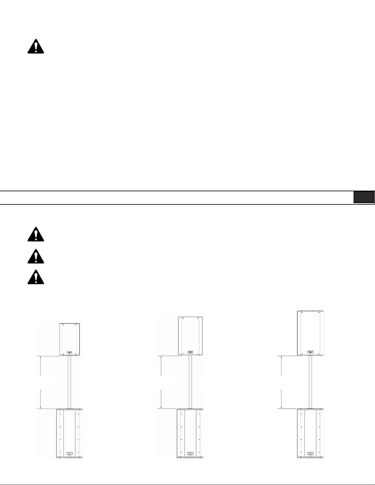
Recommended Deployment
K8: The K8 was designed to sit on the floor, stage, subwoofer enclosure, be suspended, or be pole mounted on a 35 mm diameter loudspeaker sup-
port pole. When pole-mounted to the KSub, pole length must not exceed 31 inch (787 mm).
K10: The K10 was designed to sit on the floor, stage, subwoofer enclosure, be suspended, or be pole mounted on a 35 mm diameter loudspeaker
support pole. When pole-mounted to the KSub, pole length must not exceed 28.5 inch (724 mm).
K12: The K12 was designed to sit on the floor, stage, subwoofer enclosure, be suspended, or be pole mounted on a 35 mm diameter loudspeaker
support pole. When pole-mounted to the KSub, pole length must not exceed 26.5 inch (673 mm).
KSub: The KSub was designed to sit on the floor or on the stage. A threaded pole cup on the top of the enclosure accepts a M20 threaded 35 mm
loudspeaker mounting pole. There are additional M20 speaker poles available from third party suppliers. Rubber feet on the enclosure’s bottom help
to minimize enclosure movement during operation. Do not pole mount or stack more than one enclosure on top of the KSub enclosure. As the casters
will wear during normal use, it may be required to insert small foam pieces between the wheels and frames to minimize rattling at high output levels.
K8 WARNING! Do not use a loudspeaker support pole longer than 31 inch (787 mm) when supported by the KSub subwoofer.
K10 WARNING! Do not use a loudspeaker support pole longer than 28.5 inch (724 mm) when supported by the KSub subwoofer.
K12 WARNING! Do not use a loudspeaker support pole longer than 26.5 inch (673 mm) when supported by the KSub subwoofer.
K10
K SERIES
POLE
24"
(612 mm)
24.5"
(622 mm)
K8
K SERIES
POLE
24.5"
(622 mm)
K12
K SERIES
POLE
KSub
KSub
KSub
7
Page 8
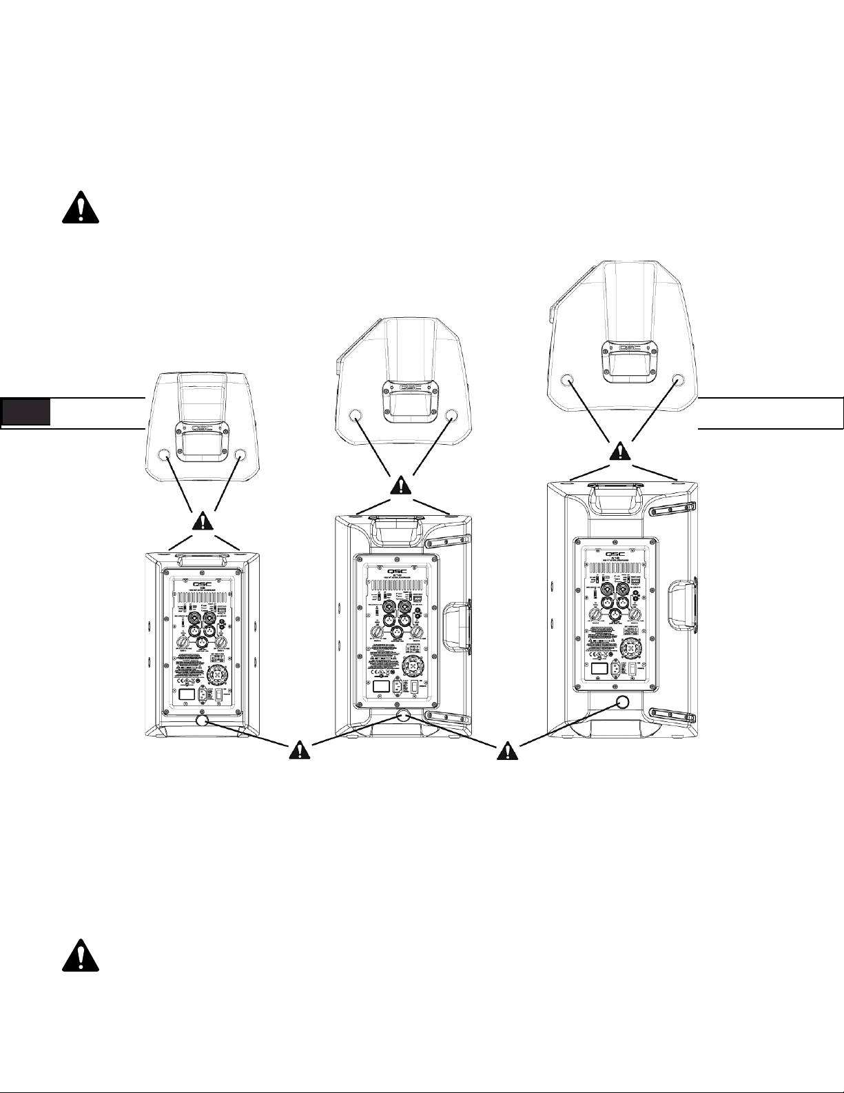
Integrated Suspension Points (suspended installations)
The K8, K10 and K12 enclosures each feature three load-rated M10 installation points.
As shipped from the factory, each pick point has a rubber plug installed to retain the sleek look of the enclosure. These installation points are designed
for use with the eyebolts included in the available accessory kit, model number K SERIES M10 KIT. The installation points may also be used with any
forged shoulder eyebolt with an M10 thread, provided the length of the thread is no more than 0.8 inch (20 mm).
Ensure all pick-point fasteners are installed and correctly tightened in order to maintain enclosure’s rated strength. Use either
QSC’s M10 forged shoulder eye bolts contained in K SERIES M10 KIT or an M10 forged shoulder eyebolt with a thread length no more
than 0.8 inch (20 mm). Contact QSC Technical Services department for complete information.
ENG ENG
K8 K10 K12
Cooling in Installed Applications
This is a self-powered loudspeaker containing an internal power amplifier that produces heat. Allow a minimum of 6" (152 mm) clearance at cabinet
back for convection cooling. Keep anything that might restrict airflow away from the rear of the enclosure (i.e draperies, fabric, etc...).
Do not install enclosures with their rear panels exposed to direct sunlight. Direct sunlight will heat the amplifier module and reduce
its ability to produce full output. Install sunshades if the application merits. Maximum ambient temperature for full performance to
specification is 50° C (122° F). Do not install enclosures where exposed to rain or other water sources. The enclosure is not weatherproof. Outdoor installations must provide protection from the elements.
8
Page 9
AC Mains
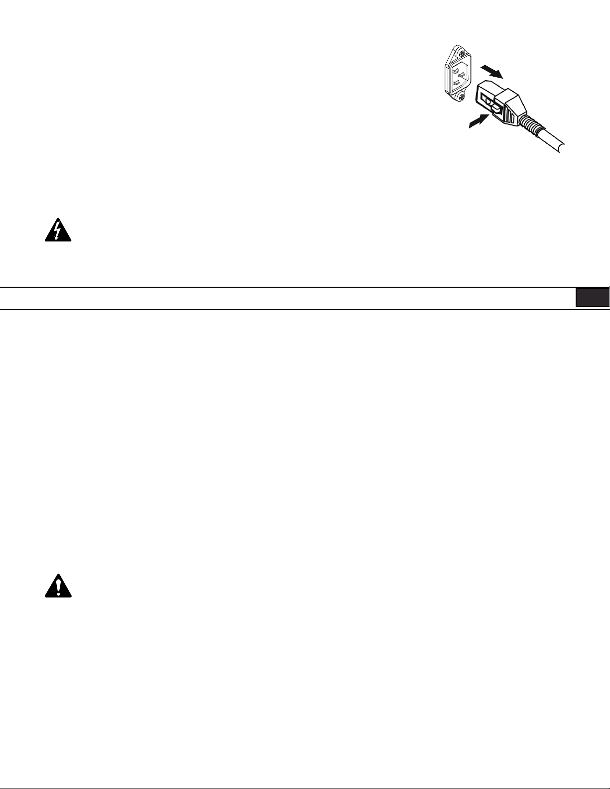
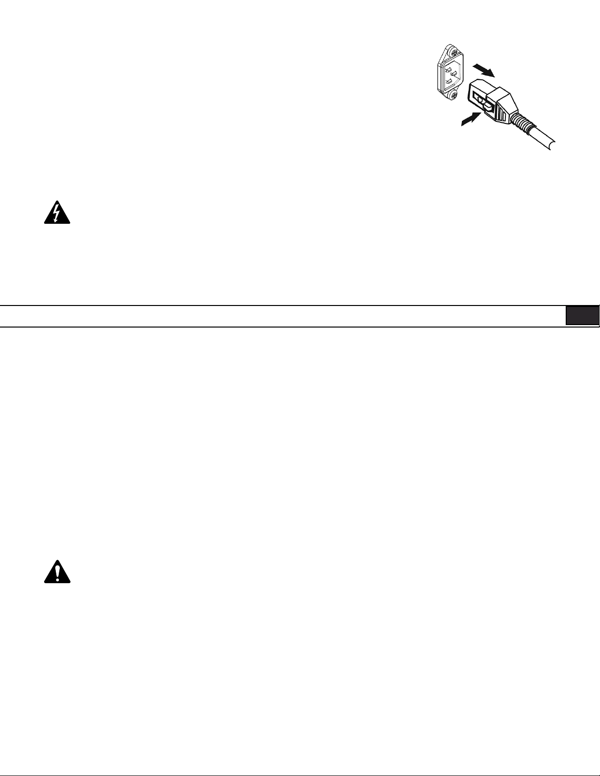
Connect AC power to the IEC socket on the back of the amplifier by locating the IEC connector-end of the
AC power cord and inserting it fully into the IEC inlet on the power amplifier module. NOTE: Turn off the AC
power switch before connecting AC power.
The V-LOCK power cord has a special latching feature to prevent the power cord from being unintentionally
removed. The IEC plug and socket are both blue in color so the power cord can be identified as a K Series
loudspeaker cord. If the QSC supplied cord becomes lost or damaged, a standard replacement 18 gauge IEC
power cord may be used. However, the latching system will only function with a V-LOCK power cord available
from QSC Audio Products, LLC.
The K Series is fed by a universal power supply. This power supply is capable of operating the system with input AC power voltages ranging
from 100 - 240 VAC at 50 – 60 Hz.
Use only the power cable that is correct for your location.
You may discard any other power cables, find an appropriate recycling opportunity or keep them if travel to other regions with the K Series
product is likely.
AC Mains Disconnection
Turn the AC power switch to the off position. To remove the AC mains cord, grasp the IEC connector’s plastic body, press the yellow latch release button and pull, removing the connector from the socket.
Power Switch
Push in on the top of the rocker switch to apply AC mains power to the powered loudspeaker. Push in on the bottom of the rocker switch to turn the
powered loudspeaker off.
When turned on, the green STANDBY indicator LED and the red LIMIT (limiter) indicator LED on the rear panel will illuminate; after a few seconds the
red LIMIT indicator and the green STANDBY will extinguish, and the blue POWER indicator LED will illuminate.
Rear LED POWER Indicator
The blue LED POWER indicator on the rear panel will illuminate when the AC Power switch is in the “ON” position, the unit is not in standby, the
AC mains power cord is connected properly, and the AC mains are functioning properly. The rear LED POWER indicator will extinguish when the AC
Power switch is in the “off” position, AC mains power has been removed from the loudspeaker, or the amplifier enters standby.
If the rear LED POWER indicator does not illuminate when the Power switch is placed in the “on” position during the first 5 minutes of power being
applied, verify the AC mains line cord is properly attached to the loudspeaker and plugged into the AC outlet. Verify the outlet is functioning properly.
If the AC mains cordset is serviceable and the AC mains outlet is operating properly, but the loudspeaker fails to operate, the loudspeaker may
require servicing. Contact QSC’s Technical Services department.
System Power Sequencing
Proper power turn on/turn off sequencing can help to prevent unexpected sounds from being produced by the system (pops, clicks,
thumps). These unintended sounds can be unpleasant and take away from the overall professionalism of the presentation. Always
follow the rule that speakers are “last on, first off”.
Power On Sequence: Bring the output level control of the mixer (or other audio source) feeding your speakers to its minimum position. Turn on all
source devices (CD players, mixers, instruments), turn on subwoofer, then turn on the “top-boxes” (K8, K10, K12). The level controls on your mixer
may now be brought up.
Power Off Sequence: Turn off “top boxes,” turn off subwoofer, then turn off all source devices.
If a K Series speaker is being driven from the output of another K Series unit, it should be turned on after the unit feeding it signal, and turned off
before the unit feeding signal.
9
Page 10
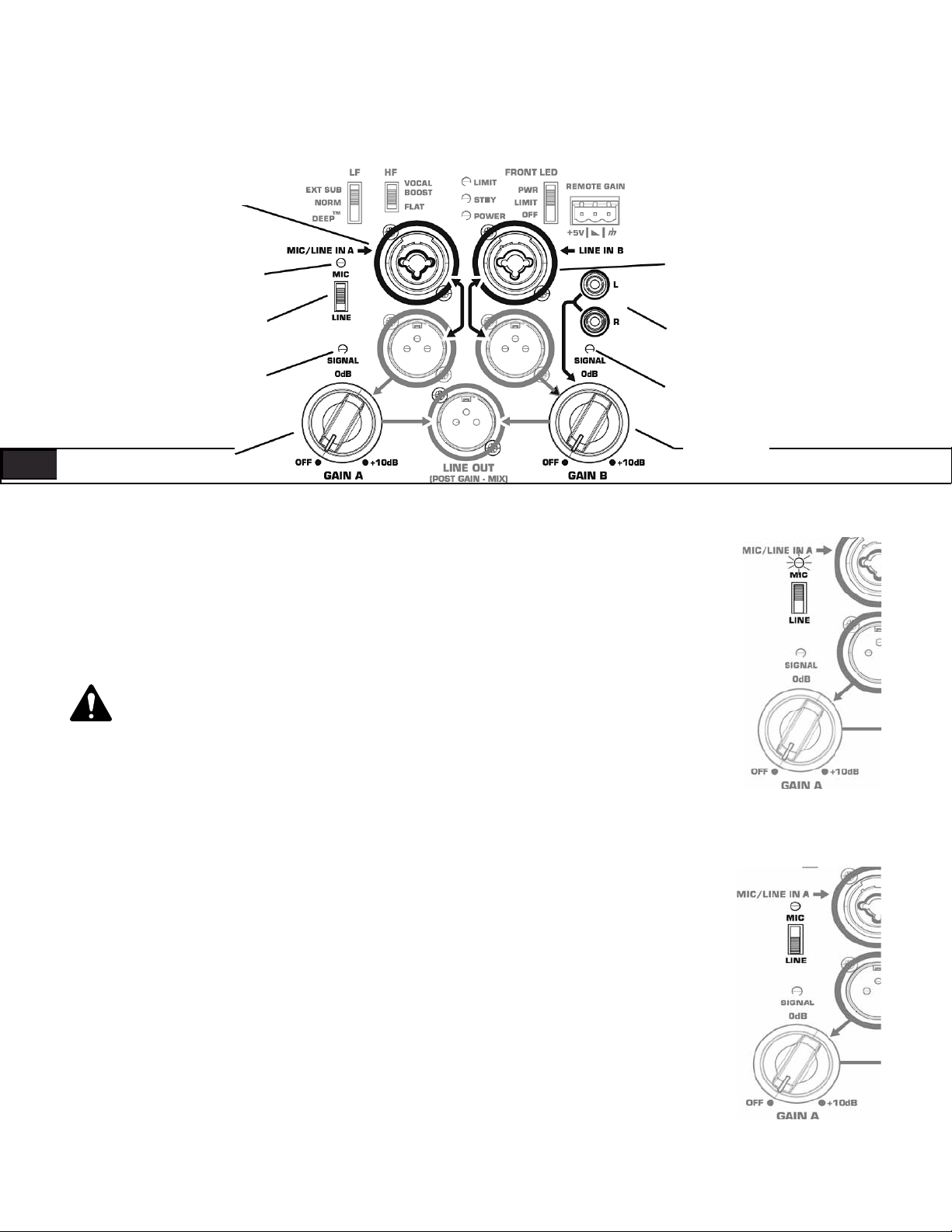
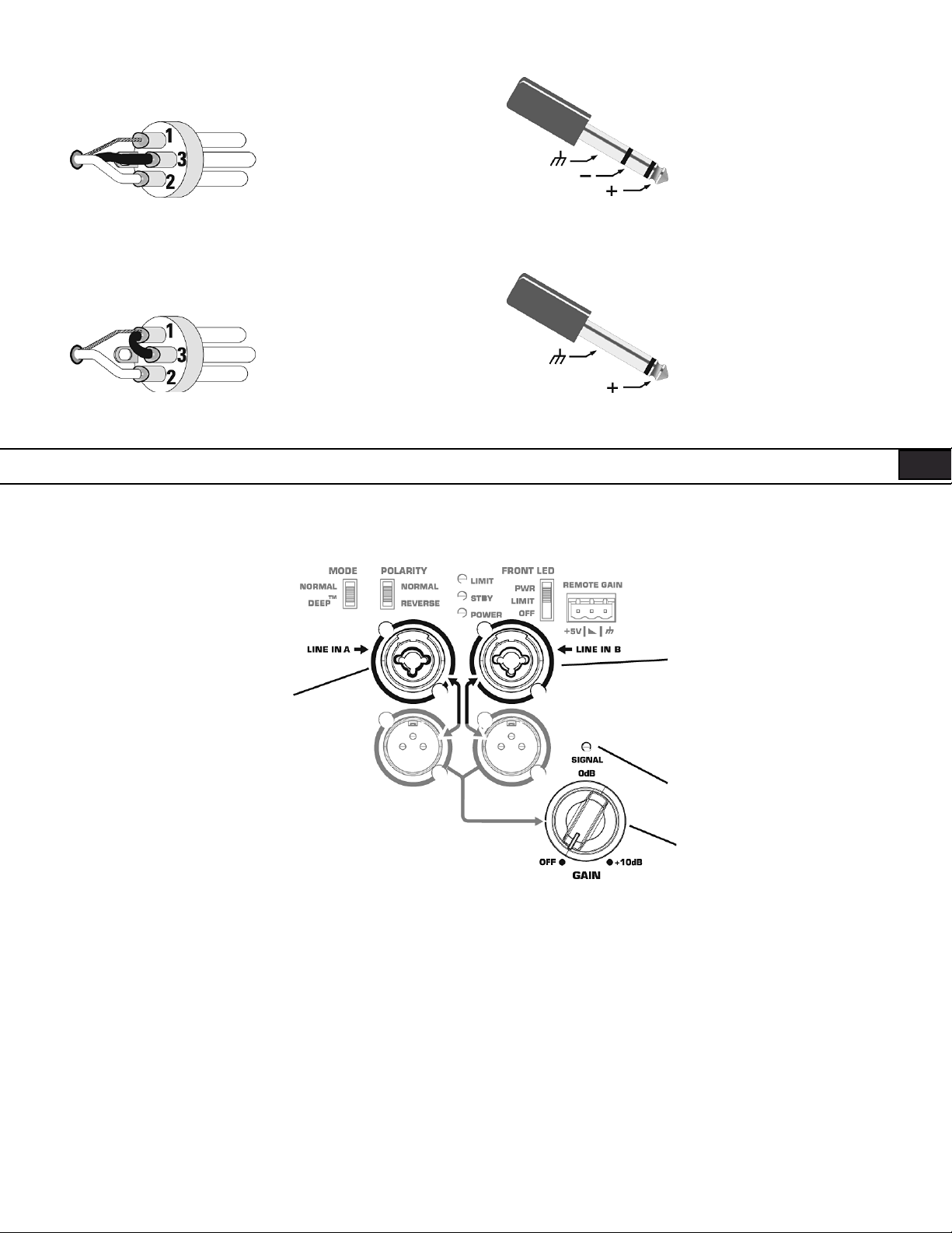
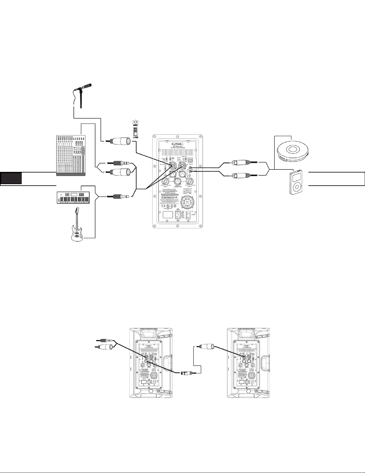
Input Connections
K8, K10, K12
Channel A MIC/Line Input
Combination XLR-M and
1/4" Phone Jack
Channel A MIC Level
Yellow LED Indicator
Channel B Line Input
Combination XLR-M
and 1/4" Phone Jack
Channel A MIC/Line
Level Switch
Channel A Green
Signal Present LED
ENG ENG
Channel A Gain
Channel B Line Input
Phono (RCA) Jacks
Channel B Green
Signal Present LED
Channel B Gain
The K8, K10 and K12 are designed to accept MIC Level and Line Level inputs with several different connectors.
There are three input connection points on the input panel. Channel A will accept MIC or Line Level inputs by
connecting a male XLR cable or a male 1/4" phone cable (either TS or TRS type may be used). For MIC Level, the
MIC/LINE selector switch must be in the “MIC” position. (Figure 5) When the selector switch is in the MIC position, activating the MIC Pre-amp, the yellow MIC level LED indicator will turn on. The MIC setting should only be
used if a microphone is connected directly to the MIC/LINE input. Note that the input does not provide phantom
power. The LINE setting should be used for most other audio inputs. (Figure 6)
The MIC setting should only be used if a microphone is connected directly to the MIC/LINE
input. Using the MIC setting for other purposes may introduce distortion. Care should be taken
when switching to the MIC position as the output level will increase significantly when the switch
is flipped.
Gain for signal delivered on the Channel A XLR/1/4" combination jack is set using the Channel A Gain knob. This
control sets the sensitivity of Channel A, and thereby the amount of signal sent to the power amplifier and, in turn
to the loudspeaker components. It also sets the amount of signal sent to the Post-Gain Line Output. The green
SIGNAL LED will illuminate when signal is present, regardless of the amount of gain as set by the Gain knob. If the
LED does not illuminate, the input is not receiving any signal or the level of the signal is significantly low. Check all
connections and the status of the device delivering the signal.
Channel B will accept Line Level input only, by connecting a male XLR cable or a male 1/4" phone cable (either TS or
TRS type may be used). Channel B will also accept mono or stereo Line Level input on a pair of RCA (phono) jacks.*
Gain for signal delivered on the Channel B line level XLR/1/4" combination jack and RCA (phono) jacks is set
using the Channel B Gain knob. The Channel B Gain knob will control the input gain of Channel B, as well as the
amount of signal sent to the Post-Gain Line Output. The green SIGNAL LED will illuminate when signal is present,
regardless of the amount of gain as set by the Gain knob. If the LED does not illuminate, the input is not receiving
any signal, or the level of the signal is significantly low. Check all connections and the status of the device delivering the signal.
Note: Unless the gain controls associated with all active inputs are set to 0 dB, the output signal from the
Post-Gain Line Output will not be at the same level as the input signal. If a “slave” speaker is intended to
playback at the same level as the “master” speaker, the gain control on the “slave” speaker should be set
to 0 dB.
10
– Figure 5 –
– Figure 6 –
Page 11
*Stereo input received at the RCA input jacks will be summed to mono.
Balanced Inputs: Connect to the plug as shown.
1 = Shield (ground)
3 = Minus (-)
2 = Plus (+)
Ground
Inverting Input
Non-inverting Input
Unbalanced Inputs: Connect to the plug as shown. If a 3 conductor (TRS) plug is used to connect an unbalanced source, Pin 3 and pin 1 must
be connected with a jumper as shown.
1 = Shield (ground)
3 = Minus (-)
2 = Plus (+)
Ground
Non-inverting Input
Input Connections
KSub
Channel B Line Input
Combination XLR-M
Channel A Line Input
Combination XLR-M
and 1/4" Phone Jack
The KSub is designed to accept Line Level inputs connected either by male XLR or 1/4" phone (TS or TRS) jack. If signal is connected to both Channel
A and Channel B, they will be summed together. The gain of the summed signal is then controlled using the Gain knob. This affects the amount of
signal sent to the amplifier and then to the loudspeaker components. The green SIGNAL LED will illuminate when signal is present, regardless of the
amount of gain as set by the Gain knob. If the LED does not illuminate, the input is not receiving any signal, or the level of the signal is significantly
low. Check all connections and the status of the device delivering the signal.
and 1/4" Phone Jack
Green Signal
Present LED
Channel A and B
Mixed Gain Knob
11
Page 12
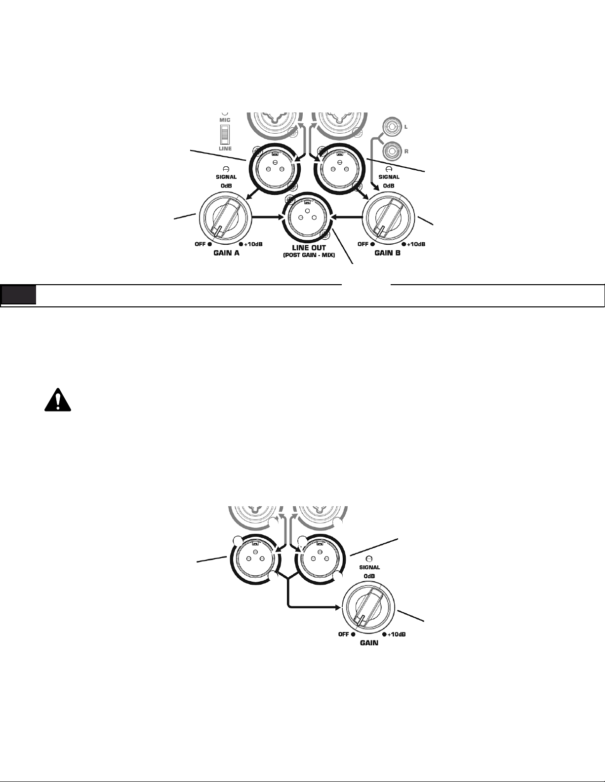
Output Connections
K8, K10, K12
Channel A Line
Level Direct Output
Channel B Line
Level Direct Output
Channel A
Gain Knob
Post-Gain
Line Output
Channel B
Gain Knob
ENG ENG
Both Channel A and Channel B have discreet direct outputs on male XLR connectors. The signal on this output is exactly equivalent to the signal from
the corresponding input. The level of the output signal is not affected by the gain setting for that channel. Additionally, signal delivered on the RCA
(phono) jacks is not present on the Channel B direct line level output.
The Post-Gain Line out male XLR connector is a mixed output of Channel A, Channel B and the RCA (phono) jacks. This mix is affected by gain knobs
on both Channel A and Channel B and the MIC/LINE switch on Channel A, but the output level is still Line Level.
WARNING! Do not connect the POST-GAIN LINE OUTPUT of a K Series system to any INPUT of the SAME UNIT. This output is
designed to send signal to OTHER K Series units or to other audio equipment. Failure to follow this warning may result in very
unpleasant sounds produced at extremely high output volumes.
Output Connections
KSub
Channel B Line
Level Direct Output
Channel A Line
Level Direct Output
Channel A and B
Mixed Gain Knob
Both Channel A and Channel B have discrete direct outputs on male XLR connectors. The signal on this output is exactly equivalent to the signal from
the corresponding input. The level of the output signal is not affected by the gain set on the subwoofer gain knob.
12
Page 13

DSP Features
The K Series features advanced DSP (digital signal processing) circuitry that performs many functions. Some functions are set at the design/production
level and are not user accessible. These functions include crossovers, time alignment, limiting and protection, thermal management and a number of
proprietary features. QSC has designed exclusive DSP functions that greatly enhance the capabilities and performance of the K Series systems.
Proprietary DSP Functions
Excursion Limiting: In addition to signal limiting to protect the amplifier and transducers from overload, the K Series utilizes a proprietary limiter that
prevents woofer over-excursion. Over-excursion occurs when a voltage presented to the woofer causes the cone to physically travel too far. This builds
up excessive heat, stresses the moving parts of the woofer, produces audible artifacts and distortion and reduces the woofer’s lifespan. The proprietary
algorithm contained in Excursion Limiting prevents over-excursion. Voltages that will harm the woofer through over-excursion are reduced enough to
prevent over-excursion without any audible compression, limiting or loss.
DEEP™: Taking advantage of the Excursion Limiter, the DEEP (Digital Extension and Excursion Processing) algorithm functions as a highly musical and
non-distorting low-frequency EQ circuit. More on the DEEP function is available in the EQ section of this manual.
Intrinsic Correction™: Introduced on QSC Concert/Touring products, Intrinsic Correction is a proprietary process and set of signal processing algorithms that address correctable characteristics of transducers and waveguides. The net result is that any K Series system will present extraordinarily
even and consistent energy throughout the physical listening area of the loudspeaker, resulting in a very musical, acoustically transparent system.
DSP User Functions
Low-frequency EQ
On the K8, K10 and K12, there are three low-frequency settings. From the factory, the switch is set to “NORM.”
This means that the loudspeaker system is producing a normal low-frequency signal through the woofer. This is
the standard setting for most applications. (Figure 7)
When using one of the top boxes with a subwoofer, the switch should be moved to the “EXT SUB” position to
engage the 100 Hz high-pass filter. It is also recommended that the 100 Hz high-pass filter be engaged when using
the K10 or K12 as a floor monitor to prevent excessive bass build up on the stage.
For extra low-frequency extension and low-end presence when using one of the top boxes without a sub, move
the switch to the “DEEP” setting. This will engage the proprietary DEEP algorithm, providing increased lowfrequency extension without causing distortion or woofer over-excursion.
On the KSub there are two low-frequency settings. From the factory, the switch is set to “NORM.” This means
that the subwoofer system is producing a non-EQ’d low-frequency signal through the woofer. This is the standard
setting for most applications. (Figure 8)
For extra low-frequency extension and low-end presence, move the switch to the “DEEP” setting. This will engage
the proprietary DEEP algorithm, providing increased low-frequency extension without causing distortion or woofer
over-excursion.
High-frequency EQ
– Figure 7 –
– Figure 8 –
On the K8, K10 and K12 there are two high-frequency settings. From the factory, the switch is set to “FLAT.” This
means that the loudspeaker system is producing a flat response through the vocal band. This is the standard setting for most applications. (Figure 9)
In voice-only reproduction, the switch can be set to the “VOCAL BOOST” setting. This will engage EQ that gives a
stronger presence for vocal intelligibility and presence. It is generally not recommended to use this setting when
playing full-range music through the system.
13
– Figure 9 –
Page 14
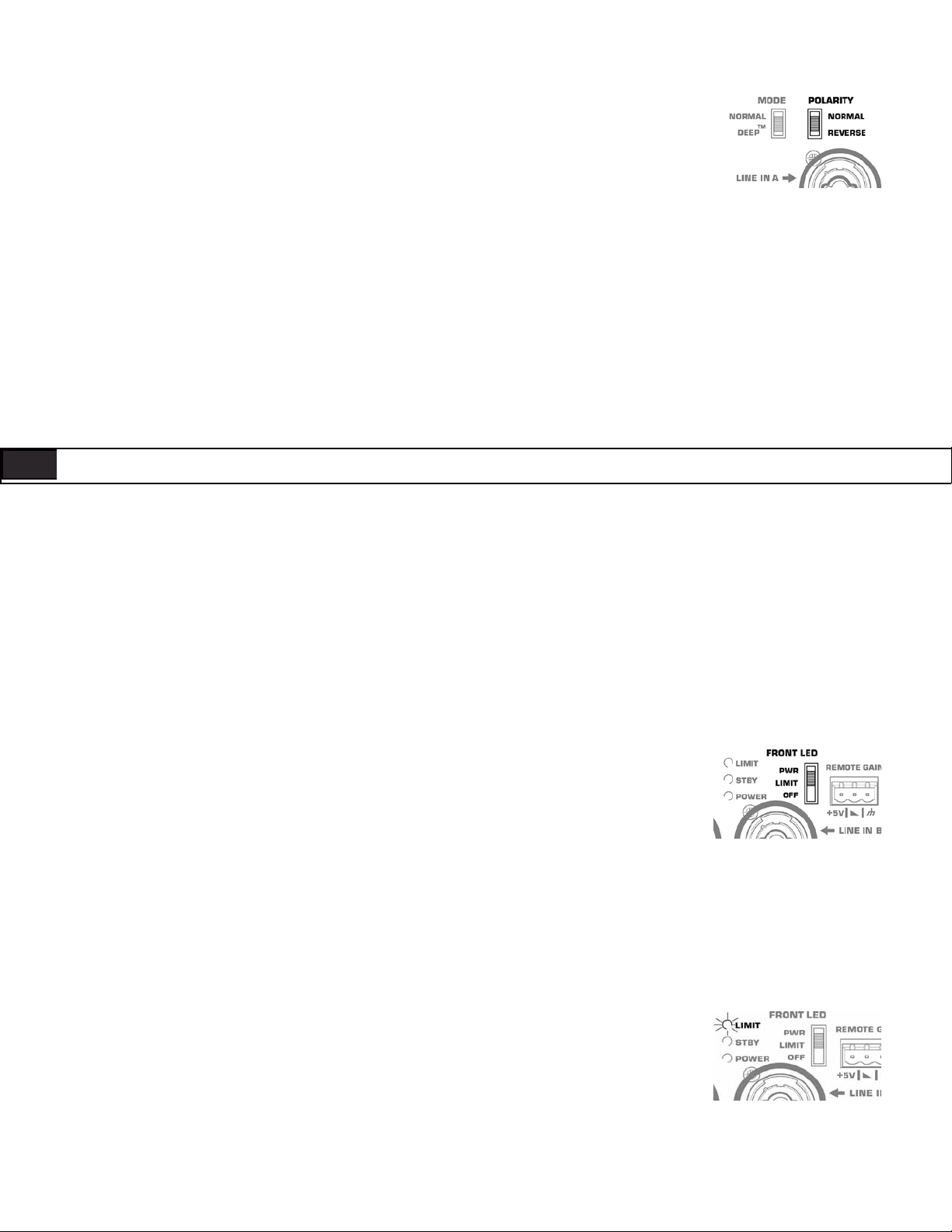
Subwoofer Polarity
Polarity (sometimes improperly referred to as phase) refers to the voltage of an input signal and whether it is a
positive or negative voltage at any given time. In most cases a positive voltage causes a woofer cone to move
forward with respect to the cabinet orientation, and a negative voltage then moves the woofer cone backward.
Most importantly, speakers reproducing the same signal or signals that are adjacent in frequency must have the
same polarity to get the maximum output. This is most important for low frequencies. Polarity can be altered by
incorrect wiring or mixer control settings. (Figure 10)
When using the KSub with K Series full range loudspeakers, NORMAL polarity will result in the best bass response
IF the full range loudspeakers are sitting on or very close to the subwoofers. If the subwoofers are some distance
away from the full range loudspeakers, polarity change may be of benefit. Start with all subwoofer POLARITY
switches in the NORMAL position. Then, with the system at or near expected operating levels, change the polarity
of each subwoofer INDIVIDUALLY. Walk around the venue and assess the overall bass response. Select the polarity
that results in the best overall system bass response.
When using only one KSub and connecting a LEFT and RIGHT stereo signal, start with the polarity switch in the
NORMAL position. With the system at a reasonable level, change the POLARITY switch and evaluate which polarity results in the most low-frequency output.
– Figure 10 –
ENG ENG
Additional Features
Standby
All K Series models are equipped with an automatic standby feature to conserve energy when the systems are not
in use. If no signal is present on any input of a K Series system or the gain knob is turned to off for five minutes,
the power amplifier will go into standby and the green STANDBY LED will illuminate. No other LEDs will illuminate
when the unit is in standby; this includes both the Rear Power LED and the Front Power LED. In this mode, the
amplifier will be powered down. A small amount of voltage will continue to flow from the AC power source into
the power supply of the K Series power module. This voltage will keep the power supply and DSP “awake” to
reduce turn on time when the system is brought out of standby. The power up time of the amplifier is negligibly
small and is shorter than the latency of the DSP, so no signal will be cut off when the K Series system is brought
out of standby. A K Series loudspeaker can also be brought out of standby manually by turning the power switch
off and then back on.
Front Power LED Functions
The Front Power LED may be set to any of three modes by the rear-mounted Power LED switch. (Figure 11)
• From the factory, the Power LED switch is set to the PWR position. The Front Power LED will illuminate when
the power switch is in the ON position and the unit is not in Standby.
• In the “OFF” position, the Front Power LED will not illuminate. This setting is recommended in applications
where the Front Power LED may be visually objectionable while the unit is operating.
– Figure 11 –
• In the LIMIT setting the Front Power LED will track the LIMIT LED on the rear of the unit. When the K Series
is in Limiting (meaning that one or more of the limiters is engaging to protect some part of the system) the
Front Power LED will glow brighter in response to the limiting function. This allows the system operator to have
awareness of the status of the limiters without needing to see the rear of the unit. For more information see the
section below on the Rear LIMIT LED. When not in limiting and when the unit is not in standby, the front power
LED will be illuminated dimly.
Rear LIMIT LED
The red LIMIT LED can indicate that limiting has taken place to protect and avoid damage to the amplifier or loudspeaker. (Figure 12) If the signal level at any frequency is too high, the DSP will limit the signal to prevent damage
and the red LIMIT LED will illuminate. If the amplifier is too hot because the SPL is too high or the environment is
too hot, the red LIMIT LED will be illuminated. If the red LIMIT LED is on when both Gain controls are at minimum, your K Series loudspeaker requires service by qualified personnel.
14
– Figure 12 –
Page 15
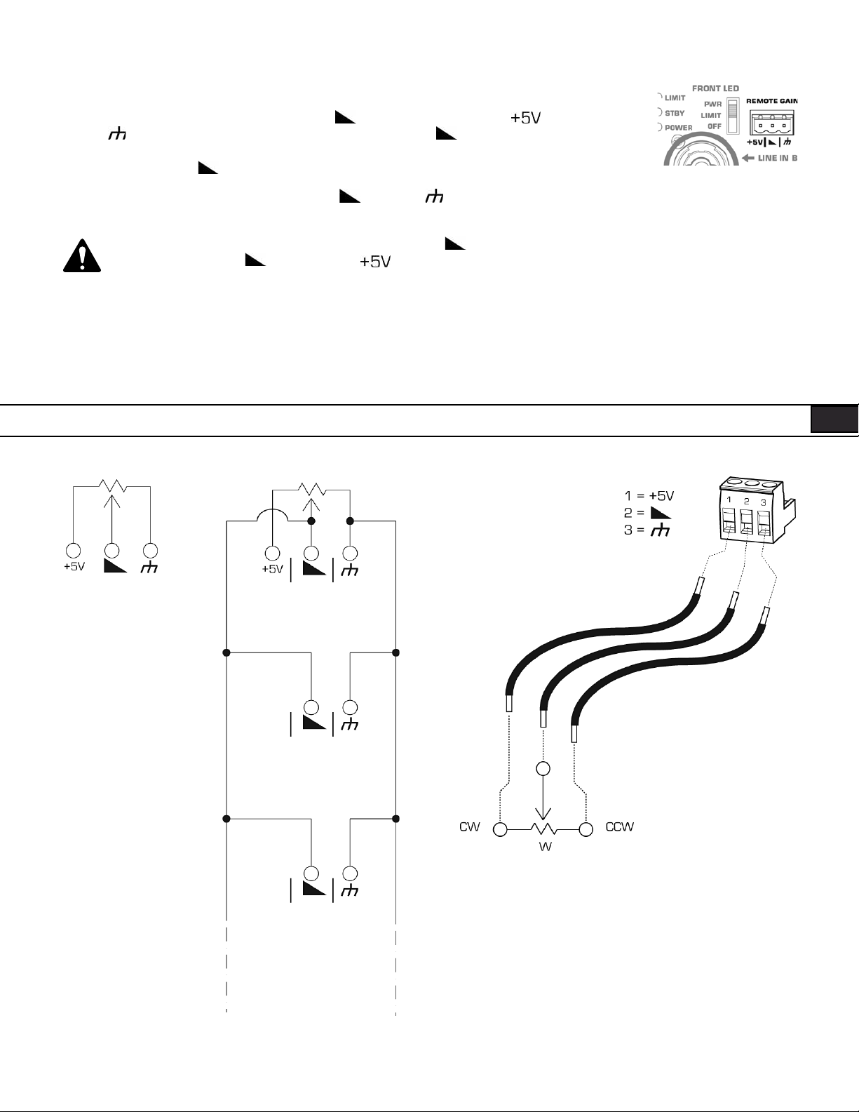
Remote Gain Attenuator
A 3 pin “Euro” connector has been provided to adjust the volume of the K Series loudspeaker or put the system
into standby. (Figure 13) By varying the voltage on the pin between +5V (provided on pin) and
ground ( pin), the volume can be linearly controlled. The voltage on the pin can be created by using a
potentiometer or provided from an external source. Many K Series systems can be controlled from a single potentiometer by connecting the pins of multiple K Series speakers together.
A relay or manual connection can be made between the pin and the pin to put the K Series system into
standby mode after 5 minutes.
WARNING: Do not put more than +5V or less than ground on the pin or else damage may
occur. Do not connect the pin directly to the pin.
Schematics of Proper Wiring for Gain Attenuator
When using a single potentiometer for one loudspeaker. (Figure 14)
When using a single potentiometer for multiple loudspeaker. (Figure 15)
Wiring to the 3 pin “Euro” connector. (Figure 16)
– Figure 13 –
– Figure 16 –– Figure 14 – – Figure 15 –
15
Page 16
Applications
Input Hookup
ENG ENG
Output Hookup
16
Page 17
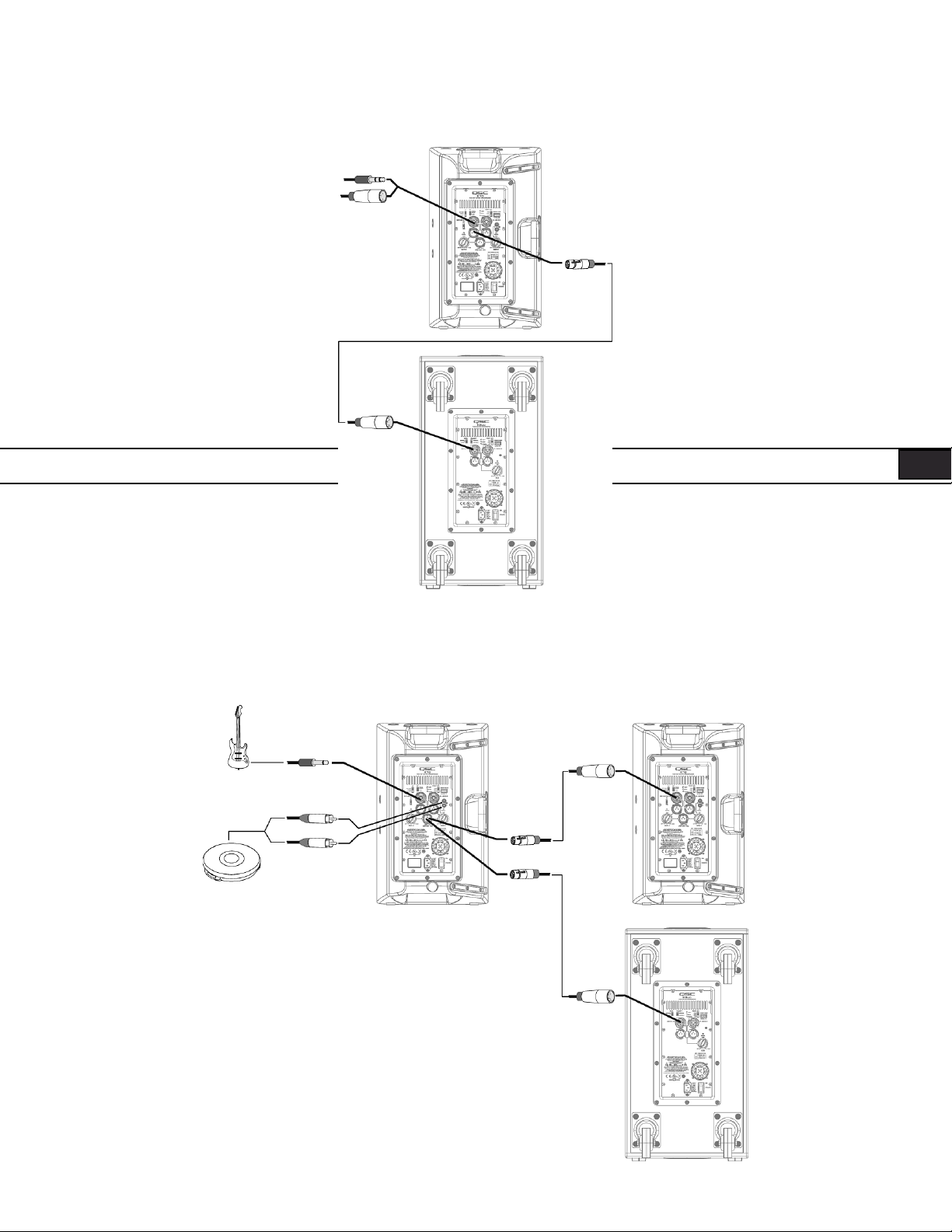
Output Hookup
17
OR
Page 18
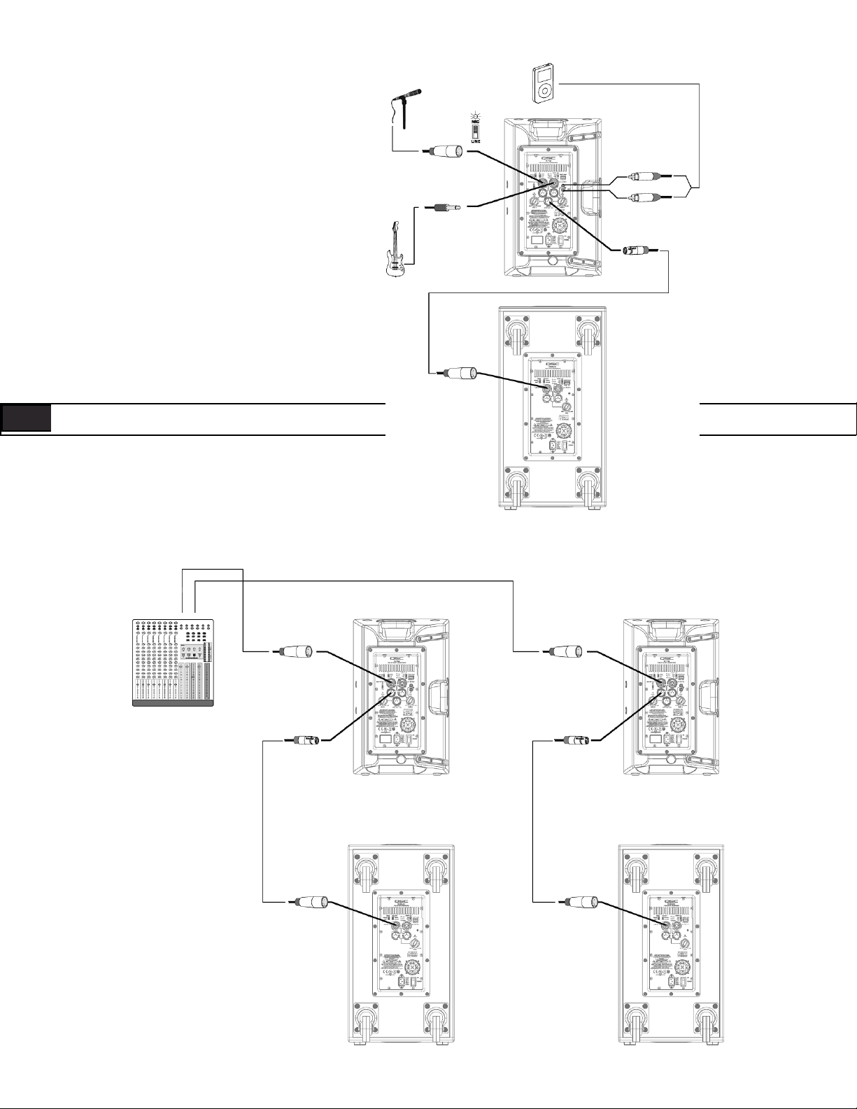
Common Standalone Small System (Mono)
ENG ENG
Common Stereo System
LEFT RIGHT
18
Page 19
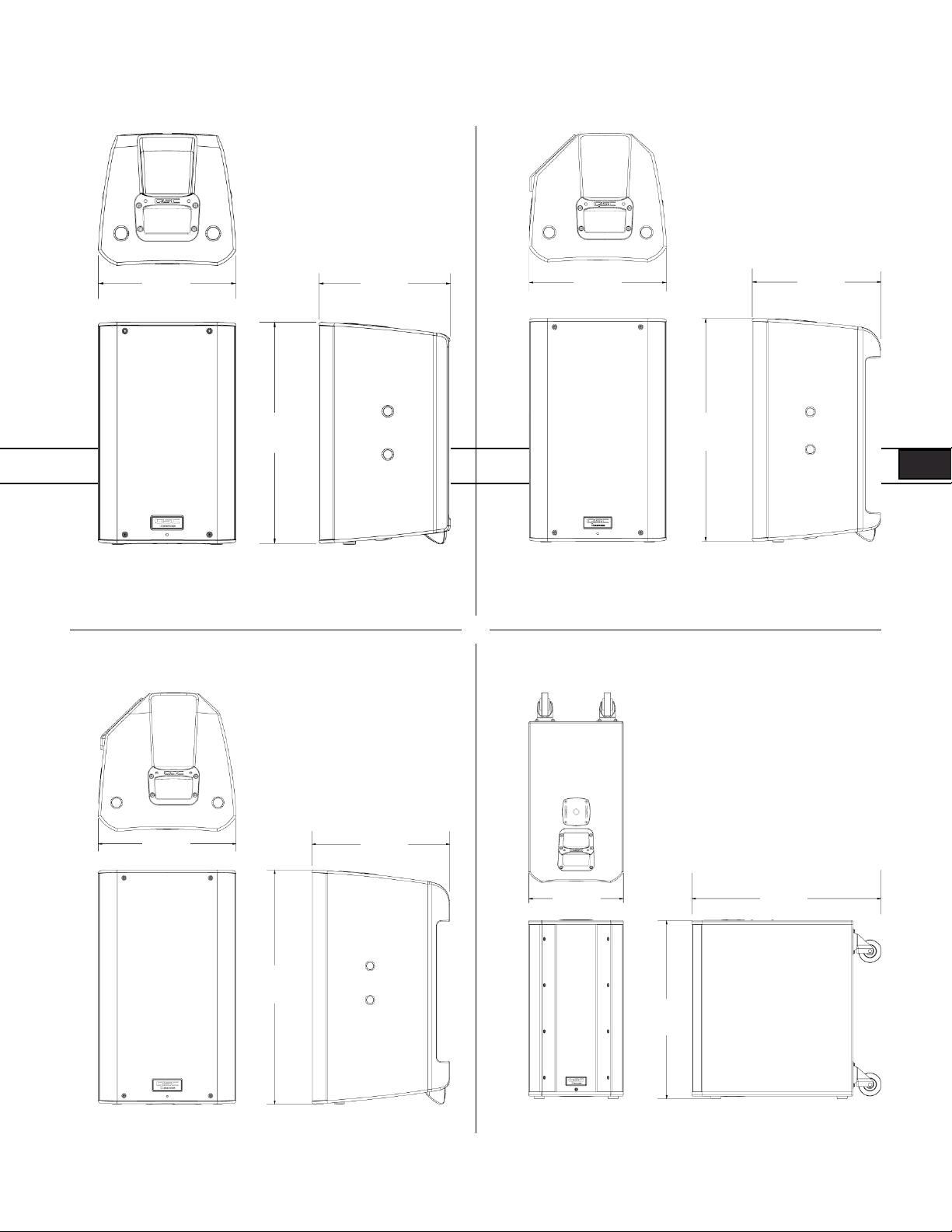
Dimensions
K8
Top
11"
280 mm
17. 7"
450 mm
10.6"
269 mm
Front Side
K10
Top
12.6"
320 mm
20.4"
519 mm
11.8"
300 mm
Front Side
K12
Top
14"
356 mm
23.7"
603 mm
14"
356 mm
Front Side
KSub
Top
14"
356 mm
26"
665 mm
Front Side
28.1"
714 mm
19
Page 20
Specifications
K8 K10 K12 KSub
Configuration Trapezoidal 2-way Multipurpose 2-way Multipurpose 2-way 4th Order Bandpass
Transducers
Low-frequency
High-frequency
Frequency Response (-6 dB) 66 Hz – 18 kHz 60 Hz – 18 kHz 52 Hz – 18 kHz 48 Hz – 134 Hz
8" cone transducer
1.75" diaphragm compression driver
10" cone transducer
1.75" diaphragm compression driver
12" cone transducer
1.75" diaphragm compression driver
2 x 12" cone transducers
ENG ENG
Frequency Range (-10 dB) 61 Hz – 20 kHz 56 Hz – 20 kHz 48 Hz – 20 kHz 44 Hz – 148 Hz
Nominal Coverage (-6 dB) 105° conical 90° conical 75° conical
Maximum SPL (1 meter) 127 dB peak 129 dB peak 131 dB peak 130 dB peak
Amplifiers
Power Output 1000 W Class D
Input Impedance (Ω) XLR / ¼": 40k balanced / 20k unbalanced • XLR / ¼" MIC mode: 2260 balanced • RCA: 10k
Controls Power • Gain A • Gain B • Mic/Line • LF Mode (Ext Sub/Norm/DEEP™) • HF Mode (Flat/Vocal Boost)
Indicators Power • Signal A • Signal B • Standby • Limit • Mic Power • Signal • Standby • Limit
Connectors Balanced female XLR / ¼" line/mic level input • Balanced female XLR / ¼" line level input • Dual Balanced male XLR
Cooling On demand, 50 mm variable speed fan
Amplifier Protection Thermal limiting • Output overcurrent • Overtemperature muting • GuardRail™
Transducer Protection Thermal limiting • Excursion limiting
AC Power Input Universal power supply 100 - 240 VAC, 50 - 60 Hz
AC Power Consumption
1/8 Power
Front LED (On/Off/Limit)
full range line level out • Balanced male XLR “mix” out • Stereo RCA line level input • Remote gain control • Locking
IEC power connector
100 VAC, 2.3 A • 120 VAC, 2.01 A • 230 VAC, 1.13 A
Power • Gain • LF Mode (Normal/
DEEP™) • Polarity (Normal/Reverse)
• Front LED (On/Off/Limit)
Dual balanced female XLR / ¼"
line level input • Dual Balanced
male XLR full range line level out •
Remote gain control • Locking IEC
power connector
Enclosure Impact resistant ABS Painted birch plywood
Finish Black Paint Black textured paint
Grille Black powder coated 18 gauge steel
Dimensions (HWD) 17.7" x 11" x 10.6"
450 mm x 280 mm x 269 mm
Weight (Net) 27 lb (12.2 kg) 32 lb (14.5 kg) 41 lb (18.6 kg) 74 lb (33.6 kg)
Available Accessories K8 TOTE • K8 YOKE •
K SERIES M10 KIT
Specifications subject to change without notice.
20.4" x 12.6" x 11.8"
519 mm x 320 mm x 300 mm
K10 TOTE • K10 YOKE •
K SERIES M10 KIT
23.7" x 14" x 14"
603 mm x 356 mm x 356 mm
K12 TOTE • K12 YOKE •
K SERIES M10 KIT
26" x 14" x 28.1" (including casters)
665 mm x 356 mm x 714 mm
KSub COVER
20
Page 21
Mailing Address:
QSC Audio Products, LLC
1675 MacArthur Boulevard
Costa Mesa, CA 92626-1468 USA
Telephone Numbers:
Main Number: 714-754-6175
Sales & Marketing: 714-957-7100 or toll free (USA only) 800-854-4079
Customer Service: 714-957-7150 or toll free (USA only) 800-772-2834
Facsimile Numbers:
Sales & Marketing FAX: 714-754-6174
Customer Service FAX: 714-754-6173
World Wide Web:
qscaudio.com
E-mail:
info@qscaudio.com
service@qscaudio.com
QSC™ is a registered trademark of QSC Audio Products, LLC., “QSC” and the QSC logo are registered with the U.S. Patent and Trademark Office.
Tilt-Direct, Intrinsic Correction, DEEP and GuardRail are all trademarks of QSC Audio Products, LLC., All trademarks are the property of their respective owners.
K Series User Manual 07/21/11
© Copyright 2009 – 2011, QSC Audio Products, LLC., US D591724, US D609216, Worldwide Patent Pending
Page 22

Serie K
Manual del usuario
K8 – Sistema de altavoces activo de dos direcciones, con inclinación de 105°, de 1000 W y 8" (200 mm)
K10 – Sistema de altavoces activos de dos direcciones, con inclinación de 90°, de 1000 W y 10" (250 mm)
K12 – Sistema de altavoces activo de dos direcciones, con inclinación de 75° , de 1000 W y 12" (300 mm)
KSub – Sistema de subwoofer activo, de 12" (300 mm) y 1000 W, de paso de banda doble de 4.° orden
Page 23
IMPORTANTES PRECAUCIONES DE SEGURIDAD Y EXPLICACIÓN DE LOS SÍMBOLOS
¡ADVERTENCIA!
PRECAUCIÓN: PARA REDUCIR EL RIESGO DE DESCARGA ELÉCTRICA, NO QUITE LA CUBIERTA DEL
AMPLIFICADOR. EL INTERIOR NO CONTIENE PIEZAS A LAS QUE EL USUARIO PUEDA DAR SERVICIO.
REFIERA EL SERVICIO A PERSONAL CALIFICADO.
El símbolo de un rayo con punta de flecha dentro de un triángulo equilátero tiene el propósito de alertar al usuario de la presencia de
voltaje “peligroso” no aislado dentro de la caja del producto, que puede ser de suficiente magnitud para constituir un riesgo de descarga
eléctrica a los seres humanos.
El signo de exclamación dentro de un triángulo equilátero tiene la intención de alertar al usuario de la presencia de importantes
instrucciones de operación y mantenimiento (servicio) en este manual.
1. Lea estas instrucciones.
2. Conserve estas instrucciones.
SPA SPA
3. Observe todas las advertencias
4. Siga todas las instrucciones
5. ADVERTENCIA: Para prevenir incendios o descargas eléctricas, no exponga este equipo a la lluvia ni a la humedad. No use este aparato cerca del agua.
6. Límpielo sólo con un paño seco.
7. Deje una separación mínima de 6” (152 mm) detrás de la caja del sistema de enfriamiento por convección. Mantenga cualquier elemento que pudiera
restringir el flujo de aire lejos de la parte posterior de la caja (por ejemplo, cortinas, telas, etc.). No obstruya ninguna abertura de ventilación. Este
producto contiene un amplificador interno de potencia eléctrica que produce calor.
8. No lo instale cerca de fuentes de calor tales como radiadores, registros térmicos, estufas ni otros aparatos (incluso amplificadores) que produzcan calor.
9. No anule la característica de seguridad del enchufe con conexión a tierra del cable eléctrico de tres patillas de tipo “Edison”. El enchufe con conexión a
tierra tiene dos hojas y una patilla de conexión a tierra. La tercera patilla se suministra para su seguridad. Si el enchufe que se le proporciona no cabe en
su tomacorriente, consulte con un electricista para reemplazar el tomacorriente obsoleto. No corte la patilla de conexión a tierra ni utilice un adaptador
que anule el circuito de conexión a tierra. Este aparato debe estar correctamente conectado a tierra para su seguridad.
10. Proteja el cable de alimentación para que no se camine sobre él ni se le comprima, particularmente en los enchufes, los receptáculos y el punto en donde
éstos salen del aparato.
11. El acoplador del equipo es la desconexión de la línea principal de CA y debe permanecer fácilmente operable después de la instalación.
12. Use sólo piezas/accesorios especificados por QSC Audio Products, LLC.
13. Use sólo con herraje, soportes y componentes vendidos con el aparato o por QSC Audio Products,LLC.
14. Desenchufe el aparato durante tormentas eléctricas o cuando no lo vaya a usar durante periodos prolongados de tiempo.
15. Refiera todo el servicio a personal calificado. Es necesario dar servicio al aparato cuando sufra algún daño, como cuando se daña el cable de alimentación
eléctrica o el enchufe, cuando se derraman líquidos o caen objetos sobre el aparato, cuando éste ha estado expuesto a la lluvia o humedad, cuando no
opere normalmente o cuando se haya caído.
16. Antes de colocar, instalar, montar o suspender cualquier producto de altavoz, inspeccione todo el equipo físico, la suspensión, los gabinetes, los
transductores, los soportes y el equipo asociado para detectar la existencia de daños. Cualquier componente faltante, corroído, deformado o no
clasificado para carga podría reducir de manera significativa la resistencia de la instalación, y deberá corregirse de inmediato. Use sólo herraje que esté
clasificado para las condiciones de carga de la instalación y cualquier posible carga excesiva inesperada a corto plazo. Nunca exceda el valor nominal del
equipo físico ni del dispositivo.
17. Consulte a un ingeniero profesional con la debida licencia cuando surjan dudas o preguntas referentes a la instalación física del equipo.
18. El equipo no debe quedar expuesto a goteo o salpicaduras y no deberán colocarse en su superficie objetos llenos de líquido, tales como floreros.
2
Page 24
Garantía (sólo para EE.UU.; para otros países, consulte con su vendedor o
distribuidor)
Garantía limitada de 3 años de QSC Audio Products
QSC Audio Products, LLC (“QSC”) garantiza que sus productos estarán libres de materiales y mano de obra defectuosos durante un período de tres (3) años
a partir de la fecha de la venta, y que reemplazará las piezas defectuosas y reparará los productos que no funcionen bien bajo esta garantía, cuando el defecto
ocurra bajo condiciones normales de instalación y uso, –siempre y cuando la unidad se devuelva a nuestra fábrica o a una de nuestras estaciones autorizadas
de servicio mediante transportación prepagada con una copia del comprobante de compra (esto es, el recibo de la compra). Esta garantía requiere que el
examen del producto devuelto indique, en nuestra opinión, un defecto de fabricación. Esta garantía no se extiende a ningún producto que hubiera estado
sometido a uso indebido, negligencia, accidente, instalación incorrecta, o en el que se hubiera quitado o modificado el código de la fecha. QSC tampoco
será responsable por daños incidentales y/o emergentes. Esta garantía le otorga derechos legales específicos. Esta garantía limitada es libremente transferible
durante el período de la misma.
El cliente podría gozar de derechos adicionales, que podrían variar de un estado a otro.
En caso de que este producto fuera fabricado para exportación y venta fuera de los Estados Unidos o sus territorios, entonces no será aplicable esta garantía
limitada. La eliminación del número de serie en este producto, o la compra de este producto de un distribuidor no autorizado, anulará esta garantía limitada.
Esta garantía se actualiza periódicamente. Para obtener la versión más reciente de la declaración de garantía de QSC, visite www.qscaudio.com.
Comuníquese con nosotros al teléfono 800-854-4079 o visite nuestro sitio en Internet en www.qscaudio.com.
Declaración de la FCC
NOTA: Este equipo ha sido probado y se ha determinado que cumple con los límites de un dispositivo digital Clase B, en virtud de la parte 15 de las reglas de
la FCC.
Estos límites están diseñados para proporcionar protección razonable contra interferencia dañina en una instalación residencial. Este equipo genera, utiliza y
puede irradiar energía de radiofrecuencia y por lo tanto, si no se instala y utiliza de conformidad con las instrucciones, podría causar interferencia dañina para
las radiocomunicaciones. Sin embargo, no hay garantía que no ocurrirá interferencia en una instalación en particular. Si este equipo interfiere con la recepción
de radio o televisión, lo cual se puede determinar encendiendo y apagando el equipo, se recomienda al usuario que trate de corregir la interferencia por uno
de los siguientes métodos:
• Reoriente o reubique la antena receptora.
• Aumente la separación entre el equipo y el receptor.
• Conecte el equipo en un tomacorriente de un circuito diferente al cual está conectado el receptor.
• Consulte al distribuidor o a un técnico experimentado de radio o TV para solicitar ayuda.
Contenido del paquete
K8, K10, K12
(1) Sistema de altavoces
(1) Cable de alimentación bloqueante
(1) Enchufe conector de estilo europeo, de tres patillas
KSub
(1) Sistema de subwoofer
(1) Cable de alimentación bloqueante
(1) Poste roscado M20 para altavoces
(1) Diagrama de conexión de la K Series
(1) Advertencia Hoja de Información
(1) Enchufe conector de estilo europeo, de tres patillas
(1) Diagrama de conexión de la K Series
(1) Advertencia Hoja de Información
3
Page 25
Características
K8
1. Caja de ABS
2. Parrilla de acero
3. Indicador LED de encendido, en la
parte delantera
4. Asas de aluminio fundido
7
4
1
7
6
7
2
5. Módulo de alimentación eléctrica
5
6. Puntos de instalación M10
7. Puntos de conexión del yugo M5
8. Casquillo para poste Tilt-Direct™
de ángulo doble
9
9
8
3
7
6
9. Patas antirresbalamiento
SPA SPA
7
4
K10
1
1. Caja de ABS
6
2. Parrilla de acero
3. Indicador LED de encendido, en la
parte delantera
4. Asas de aluminio fundido
5. Módulo de alimentación eléctrica
6. Puntos de instalación M10
7. Puntos de conexión del yugo M5
8. Casquillo para poste Tilt-Direct™
de ángulo doble
9. Patas antirresbalamiento
7
9
4
8
2
3
9
7
7
5
6
4
4
Page 26
7
K12
1. Caja de ABS
2. Parrilla de acero
3. Indicador LED de encendido, en la
parte delantera
4. Asas de aluminio fundido
5. Módulo de alimentación eléctrica
6. Puntos de instalación M10
7. Puntos de conexión del yugo M5
8. Casquillo para poste Tilt-Direct™
de ángulo doble
9. Patas antirresbalamiento
4
1
7
9
4
8
6
2
3
99
7
7
7
5
6
4
KSub
1. Caja de madera contrachapada de
abedul
2. Indicador LED de encendido, en la
parte delantera
3. Puerto acústico
4. Asas de aluminio fundido
5. Módulo de alimentación eléctrica
6. Receptáculo del poste roscado M20
7. Ruedecillas de servicio pesado de 3"
8. Patas antirresbalamiento
6
1
4
3
5
2
4
8
7
7
5
Page 27
Aplicaciones
La serie K ha sido diseñada principalmente para el refuerzo portátil de
audio. Esto incluye una variedad de usos en refuerzo para artistas y
presentadores. Los modelos K8, K10 y K12 están todos diseñados para
funcionar bien en su propio audio de intervalo completo. Pueden usarse
solos, en pares en estéreo, o en sistema distribuidos o con demora.
Funcionan extraordinariamente bien, como sistemas principales de refuerzo
y también como monitores de piso (únicamente los modelos K10 y K12).
(Figura 1)
Los modelos K8, K10 y K12 está todos equipados con un casquillo de poste
de 35 mm que permite la utilización en un soporte para altavoces, o en un
poste sobre un subwoofer. El casquillo para postes cuenta con el sistema
Tilt-Direct™ de QSC para inclinar las cajas 7,5 grados hacia abajo al estar
sobre el poste. (Figura 2)
Los modelos K8, K10 y K12 también tienen características diseñadas para
diversos métodos de suspensión. Cuentan con insertos roscados M10 para
suspensión con armellas. También hay accesorios de yugo (números de
modelo: K8 YOKE, K10 YOKE, K12 YOKE) para cada modelo que pueden
montarse a los lados de la caja o en su parte superior e inferior. Estos yugos
permiten un montaje rígido a estructuras, así como la rotación del sistema
de altavoces. (Figura 3)
– Figura 1 –
SPA SPA
Para la extensión y mejora de frecuencias extra bajas, el modelo KSub es
un complemento perfecto al resto de la serie K. Los modelos K8, K10 y
K12 tienen un filtro seleccionable de paso alto para uso con el subwoofer.
El KSub incluye un filtro de paso bajo fijo, de modo que pueda aceptar la
entrada de rango completo.
El KSub tiene cuatro ruedecillas grandes para una máxima facilidad de
transporte. El casquillo del poste en la parte superior de la caja cuenta con
un inserto roscado M20. El poste incluido para el altavoz se atornilla en el
casquillo para lograr un ajuste firme. (Figura 4)
– Figura 2 –
– Figura 3 –
– Figura 4 –
6
Page 28
Instalación
Antes de colocar, instalar, montar o suspender cualquier producto de altavoz, inspeccione todo el equipo físico, la suspensión, las cajas, los
transductores, los soportes y el equipo asociado para detectar la existencia de daños. Cualquier componente faltante, corroído, deformado o
no clasificado para carga podría reducir de manera significativa la resistencia de la instalación o colocación. Cualquier condición de este tipo reduce
gravemente la seguridad de la instalación y debe corregirse de inmediato. Utilice sólo el equipo físico clasificado para las condiciones de carga de la
instalación y cualquier posible sobrecarga inesperada de poca duración.
Nunca exceda el valor nominal del equipo físico ni del dispositivo.
Consulte a un ingeniero profesional con la debida licencia con respecto a la instalación del equipo físico. Asegúrese de comprender y acatar todas las
normativas locales, estatales y nacionales referentes a la seguridad y operación de altavoces y equipos relacionados.
Despliegue recomendado
K8: El modelo K8 fue diseñado para colocarse en el piso, escenario, caja de subwoofer, ser suspendido o montarse sobre un poste de soporte para altavoces
de 35 mm de diámetro.. Cuando se monta en un poste al KSub, la longitud del poste no debe ser superior a 31 pulgadas (787 mm).
K10: El modelo K10 fue diseñado para colocarse en el piso, escenario, caja de subwoofer, ser suspendido o montarse sobre un poste de soporte para
altavoces de 35 mm de diámetro.. Cuando se monta en un poste al KSub, la longitud del poste no debe ser superior a 28,5 pulgadas (724 mm)
K12: El modelo K12 fue diseñado para colocarse en el piso, escenario, caja de subwoofer, ser suspendido o montarse sobre un poste de soporte para
altavoces de 35 mm de diámetro.. Cuando se monta en un poste al KSub, la longitud del poste no debe ser superior a 26,5 pulgadas (673 mm).
KSub: El modelo KSub fue diseñado para apoyarse en el piso o escenario.. Una conexión roscada y acopada para poste en la parte superior de la caja
acepta un poste roscado M20 de 35 mm para el montaje de altavoces. Otros proveedores ofrecen otros postes M20 para altavoces. Las patas de caucho en la
parte inferior de la caja ayudan a minimizar el movimiento de la caja durante la operación. No monte en poste ni apile más de una caja encima de la caja del
KSub. Dado que las ruedecillas se desgastarán como consecuencia de un uso normal, es posible que se requiera insertar pequeñas piezas de espuma entre
las ruedas y los bastidores para minimizar las vibraciones a niveles altos de salida.
.
¡ADVERTENCIA SOBRE EL MODELO K8! No utilice un poste de soporte para altavoces de una longitud mayor que 31 pulgadas (780 mm)
cuando esté soportado por el subwoofer KSub.
¡ADVERTENCIA SOBRE EL MODELO K10! No utilice un poste de soporte para altavoces de una longitud mayor que 28,5 pulgadas (724 mm)
cuando esté soportado por el subwoofer KSub.
¡ADVERTENCIA SOBRE EL MODELO K12! No utilice un poste de soporte para altavoces de una longitud mayor que 26,5 pulgadas (673 mm)
cuando esté soportado por el subwoofer KSub.
K10
K SERIES
POLE
24"
(612 mm)
24,5"
(622 mm)
K8
K SERIES
POLE
24,5"
(622 mm)
K12
K SERIES
POLE
KSub
KSub
KSub
7
Page 29

Puntos de suspensión integrados (instalaciones suspendidas)
Las cajas de los modelos K8, K10 y K12 cuentan con tres puntos de instalación M10 con clasificación de carga nominal.
Tal como se envía desde la fábrica, cada punto de suspensión tiene un enchufe de caucho instalado para conservar el diseño esbelto de la caja. Estos puntos
de instalación están diseñados para uso con las armellas incluidas en el juego de accesorios disponible número de modelo K SERIES M10 KIT. Los puntos de
instalación también pueden usarse con cualquier armella de brida forjada, con una rosca M10, siempre y cuando la longitud de la rosca no sea superior a 0,8
pulgadas (20 mm).
Asegúrese de tener instalados todos los sujetadores de los puntos de suspensión, apretados correctamente para mantener la resistencia
nominal de la caja. Utilice las armellas de brida forjadas M10 de QSC contenidas en el juego K SERIES M10 KIT o una armella de brida
forjada M10 con una longitud de rosca no mayor que 0,8 pulgadas (20 mm). Comuníquese con el Departamento de Servicios Técnicos de QSC para
obtener información completa al respecto.
SPA SPA
K8 K10 K12
Enfriamiento de las aplicaciones instaladas
Éste es un altavoz autoenergizado que contiene un amplificador interno de potencia que produce calor. Deje una separación mínima de 6" (152 mm) en la
parte posterior de la caja para el enfriamiento por convección. Mantenga cualquier elemento que pudiera restringir el flujo de aire lejos de la parte posterior
de la caja (por ejemplo, cortinas, telas, etc.).
No instale las cajas con sus paneles posteriores expuestos a la luz solar directa. La luz solar directa calentará el módulo del amplificador y
reducirá su habilidad de producir una salida completa. Instale protectores solares en caso de que a aplicación lo requiera. La temperatura
ambiente máxima para lograr un rendimiento completo de acuerdo con las especificaciones es de 50 °C (122 °F). No instale las cajas donde queden
expuestas a la lluvia o a otras fuentes de agua. La caja no está diseñada a prueba de la intemperie. Las instalaciones al aire libre deben brindar
protección contra los elementos.
8
Page 30
Línea eléctrica de CA
Conecte la potencia de CA en el receptáculo IEC que se encuentra en la parte posterior del amplificador localizando
el extremo conector IEC del cable eléctrico de CA e insertándolo completamente en la entrada IEC del módulo
amplificador de potencia. NOTA: Apague el interruptor de CA antes de conectar la alimentación de CA.
El cable de alimentación V-LOCK tiene una característica especial de cierre a pestillo para evitar quitarlo por error.
El enchufe y receptáculo IEC son de color azul de modo que el cable de alimentación pueda identificarse como
un cable para altavoces serie K. Si el cable suministrado por QSC se pierde o daña, puede utilizarse un cable de
alimentación IEC estándar de reemplazo, de calibre 18. Sin embargo, el sistema de cierre a pestillo sólo funcionará
con un cable de alimentación V-LOCK disponible de QSC Audio Products, LLC.
La serie K está alimentada mediante una fuente universal de alimentación eléctrica. Esta fuente de alimentación es
capaz de operar el sistema con voltajes de entrada de alimentación de CA de 100 – 240 VCA, a 50 – 60 Hz.
Utilice únicamente el cable de alimentación correcto para su ubicación.
Puede desechar los demás cables de alimentación, reciclarlos según corresponda o guardarlos si es probable viajar a otras regiones con el producto de la serie K.
Desconexión de la fuente principal de alimentación de CA
Coloque el interruptor de CA en la posición de apagado. Para retirar el cable eléctrico de la fuente de alimentación de CA, sujete el cuerpo plástico del
conector IEC, pulse el botón de liberación del pestillo de color amarillo y hale del mismo, quitando el conector del receptáculo.
Interruptor eléctrico
Empuje hacia adentro la parte superior del interruptor basculante para aplicar el suministro eléctrico principal de CA al altavoz energizado. Empuje hacia
adentro la parte inferior del interruptor basculante para apagar el altavoz alimentado.
Cuando está encendido, se iluminarán el LED indicador de espera (STANDBY) de color verde y el LED indicador limitador (LIMIT) de color rojo en el panel
posterior; después de unos pocos segundos, se apagarán el indicador limitador de color rojo y el indicador de espera de color verde, y se iluminará el LED
indicador de potencia (POWER) de color azul.
LED indicador de potencia (POWER) del panel posterior
El LED indicador de potencia (POWER) de color azul del panel posterior se iluminará cuando el interruptor de potencia de CA se encuentre en la posición de
encendido (“ON”), la unidad no esté en espera, el cable eléctrico principal de CA esté correctamente conectado y el suministro eléctrico principal de CA esté
funcionando de manera apropiada. El LED indicador de potencia (POWER) del panel posterior se apagará cuando el interruptor eléctrico de CA se encuentre
en la posición de apagado (“off”), la alimentación eléctrica principal de CA se haya quitado del altavoz o el amplificador pase al modo de espera.
Si el indicador de potencia (POWER) del panel posterior no se ilumina cuando el interruptor correspondiente se coloca en la posición de encendido (“on”)
durante los primeros 5 minutos de aplicación de potencia, verifique que el cable del suministro eléctrico principal de CA esté correctamente conectado al
altavoz y enchufado en el tomacorriente de CA. Verifique que el tomacorriente esté funcionando correctamente.
Si el juego de cables de la alimentación principal de CA puede repararse y el tomacorriente principal de CA está funcionando correctamente, pero el
altavoz no funciona, es posible que el altavoz requiera servicio técnico. Póngase en contacto con el Departamento de Servicios Técnicos de QSC.
Secuencia de arranque del sistema
La secuencia correcta de encendido/apagado puede ayudar a prevenir sonidos inesperados que provengan del sistema (explosiones, chasquidos,
golpazos). Estos sonidos inesperados pueden ser desagradables y causar una impresión negativa con respecto al profesionalismo general de la
presentación. Siempre siga la regla que indica que los altavoces son “los últimos en encenderse , los primeros en apagarse”.
Secuencia de encendido: Coloque el control de nivel de salida del mezclador (o de otra fuente de audio) que alimenta sus altavoces en su posición mínima.
Encienda todos los dispositivos fuente (reproductores de CD, mezcladores, instrumentos), encienda el subwoofer, y luego encienda las “cajas superiores” (K8,
K10, K12). Los controles de nivel del mezclador ahora pueden llevarse a un nivel más alto.
Secuencia de apagado: Apague las “cajas superiores” , apague el subwoofer, y luego apague los dispositivos fuente.
Si un altavoz serie K está siendo impulsado desde la salida de otra unidad serie K, deberá encenderse después de la señal de la unidad que lo alimenta, y
apagarse antes de la señal de alimentación de la unidad.
9
Page 31

Conexiones de entrada
K8, K10, K12
Conector
de audio de
combinación de
entrada MIC/
Line del canal A
de tipo XLR-M y
de 1/4"
Indicador LED amarillo
de nivel MIC del canal A
Conector de audio de
combinación de entrada
Line del canal B de tipo
XLR-M y de 1/4"
Interruptor de nivel
MIC/Line del canal A
Indicador LED de
presencia de señal
de color verde del
canal A
Ganancia del
canal A
Conectores de audio
(RCA) de entrada de
línea del canal B
Indicador LED de
presencia de señal de
color verde del canal B
Ganancia del
canal B
SPA SPA
Los modelos K8, K10 y K12 están diseñados para aceptar entradas de nivel MIC y de nivel de línea con varios
conectores diferentes. Hay tres puntos de conexión de entrada en el panel de entrada. El canal A aceptará entradas
de nivel MIC o de nivel de línea conectando un cable macho XLR o un cable telefónico macho de 1/4" (puede usarse
un cable tipo TS o TRS). Para el nivel MIC, el interruptor selector MIC/LINE deberá estar en la posición “MIC”. (Figura
5) Si se activa el preamplificador MIC cuando el interruptor selector se encuentra en la posición MIC, se encenderá
el indicador LED de nivel MIC de color amarillo. El ajuste MIC sólo debe usarse si hay un micrófono conectado
directamente a la entrada MIC/LINE. Observe que la entrada no proporciona potencia fantasma. El ajuste LINE debe
usarse para la mayoría de las demás entradas de audio. (Figura 6)
El ajuste MIC sólo debe usarse si hay un micrófono conectado directamente a la entrada MIC/LINE. El
uso del ajuste MIC para otros propósitos puede introducir distorsión. Debe tenerse cuidado al conmutar
a la posición MIC ya que el nivel de salida aumentará significativamente al moverse el interruptor.
Se ajusta la ganancia para la señal suministrada en la toma de combinación XLR/1/4" del canal A utilizando la perilla de
ganancia del canal A. Este control establece la sensibilidad del canal A y, por lo tanto, la cantidad de señal enviada al
amplificador de potencia y, a su vez, a los componentes del altavoz. También establece la cantidad de señal enviada a la
salida de línea posterior a la ganancia. El indicador LED de señal (SIGNAL) de color verde se iluminará cuando haya una
señal presente, independientemente de la cantidad de ganancia establecida con la perilla de ganancia. Si no se ilumina
el indicador LED, la entrada no estará recibiendo ninguna señal o el nivel de la señal será significativamente bajo. Revise
todas las conexiones y el estado del dispositivo que suministra la señal.
– Figura 5 –
El canal B aceptará únicamente una entrada de nivel línea, conectando un cable macho XLR o un cable telefónico macho
de 1/4" (puede usarse un cable tipo TS o TRS). El canal B también aceptará una entrada monofónica o estereofónica de
nivel de línea en un par de conectores RCA (de audio).*
Se ajusta la ganancia para la señal suministrada en la toma de combinación XLR/1/4" de nivel de línea del canal B y en
los conectores RCA (de audio) utilizando la perilla de ganancia del canal B. La perilla de ganancia del canal B controlará
la ganancia de entrada del canal B, así como la cantidad de señal enviada a la salida de línea posterior a la ganancia. El
indicador LED de señal (SIGNAL) de color verde se iluminará cuando haya una señal presente, independientemente de
la cantidad de ganancia establecida con la perilla de ganancia. Si no se ilumina el indicador LED, la entrada no estará
recibiendo ninguna señal o el nivel de la señal será significativamente bajo. Revise todas las conexiones y el estado del
dispositivo que suministra la señal.
Nota: A menos que los controles de ganancia asociados con todas las entradas activas se ajusten en 0 dB, la señal
de salida desde la salida de línea posterior a la ganancia no estará en el mismo nivel que la señal de entrada. Si
un altavoz “esclavo” está configurado para reproducir en el mismo nivel que el altavoz “maestro”, el control de
ganancia del altavoz “esclavo” deberá ajustarse en 0 dB.
*La entrada estereofónica recibida en los conectores de entrada RCA se sumarán a la monofónica.
10
– Figura 6 –
Page 32

Entradas balanceadas: Conecte al enchufe como se muestra.
1 = blindado (tierra)
3 = menos (-)
2 = más (+)
Tierra
Entrada con inversión
Entrada sin inversión
Entradas no balanceadas: Conecte al enchufe como se muestra. Si se utiliza un enchufe de 3 conductores (TRS) para conectar una fuente no
balanceada, la patilla 3 y la patilla 1 deberán conectarse con un puente, tal como se muestra.
1 = blindado (tierra)
3 = menos (-)
2 = más (+)
Tierra
Entrada sin inversión
Conexiones de entrada
KSub
Conector de audio de
combinación de entrada
Conector de audio de
combinación de entrada
Line del canal A de tipo
XLR-M y de 1/4"
Line del canal B de tipo
XLR-M y de 1/4"
Indicador LED de
presencia de señal de
color verde
Perilla de ganancia mixta
del canal A y B
El KSub está diseñado para aceptar entradas de nivel de línea conectadas por medio de un conector XLR macho o un conector de audio de 1/4" (TS o TRS). Si
la señal se conecta al canal A y al canal B, ambas señales se sumarán. La ganancia de la señal sumada se controla luego utilizando la perilla de ganancia. Esto
afecta la cantidad de señal enviada al amplificador y luego a los componentes del altavoz. El indicador LED de señal (SIGNAL) de color verde se iluminará
cuando haya una señal presente, independientemente de la cantidad de ganancia establecida con la perilla de ganancia. Si no se ilumina el indicador LED,
la entrada no estará recibiendo ninguna señal o el nivel de la señal será significativamente bajo. Revise todas las conexiones y el estado del dispositivo que
suministra la señal.
11
Page 33

Conexiones de salida
K8, K10, K12
Salida directa de
nivel de línea del
canal A
Salida directa de nivel
de línea del canal B
Perilla de
ganancia del
canal A
Salida de línea
posterior a la
ganancia
SPA SPA
Tanto el canal A como el canal B tienen salidas directas discretas en los conectores XLR macho. La señal de esta salida es exactamente equivalente a la señal
proveniente de la entrada correspondiente. El nivel de la señal de salida no está afectado por el ajuste de ganancia para dicho canal. Asimismo, la señal
Perilla de ganancia
del canal B
suministrada en los conectores RCA (de audio) no está presente en la salida de nivel de línea directa del canal B.
El conector XLR macho de salida de línea posterior a la ganancia es una salida mixta del canal A, el canal B y los conectores RCA (de audio). Esta mezcla se ve
afectada por las perillas de ganancia en el canal A y en el canal B, y por el interruptor MIC/LINE en el canal A, pero el nivel de salida aún es el nivel
de línea.
¡ADVERTENCIA! No conecte la SALIDA DE LÍNEA POSTERIOR A LA GANANCIA de un sistema serie K a ninguna ENTRADA de la MISMA
UNIDAD. Esta salida está diseñada para enviar una señal a OTRAS unidades de la serie K o a otros equipos de audio. Si no se sigue esta
advertencia, podrían producirse sonidos muy desagradables a volúmenes de salida extremadamente altos.
Conexiones de salida
KSub
Salida directa de
nivel de línea del
canal B
Salida directa de
nivel de línea del
canal A
Perilla de ganancia
mixta del canal
A y B
Tanto el canal A como el canal B tienen salidas directas discretas en los conectores XLR macho. La señal de esta salida es exactamente equivalente a la señal
proveniente de la entrada correspondiente. El nivel de la señal de salida no está afectado por la ganancia fijada en la perilla de ganancia del subwoofer.
12
Page 34

Características de DSP
La serie K cuenta con circuitos avanzados de DSP (procesamiento de señales digitales) que desempeñan muchas funciones. Algunas funciones se fijan a
nivel de diseño/producción y no son accesibles para el usuario. Estas funciones incluyen cruces, alineación de tiempo, limitación y protección, administración
térmica y un número de características propietarias. QSC ha diseñado funciones DSP exclusivas que mejoran ampliamente las capacidades y el rendimiento
de los sistemas serie K.
Funciones DSP propietarias
Limitación de la excursión: Además de la limitación de la señal para proteger el amplificador y los transductores contra sobrecargas, la serie K utiliza un
limitador propietario que impide una sobre-excursión del woofer . La sobre-excursión ocurre cuando un voltaje presentado ante el woofer causa que el
cono se desplace físicamente demasiado lejos. Esto acumula excesivo calor, causa tensiones en las piezas móviles del woofer, produce artefactos audibles
y distorsión, y reduce la vida útil de woofer. El algoritmo propietario contenido en la limitación de la excursión impide una sobre-excursión. Los voltajes que
perjudicarán al woofer debido a la sobre-excursión se reducen lo suficiente como para impedir la sobre-excursión sin ninguna compresión audible, limitación
ni pérdida.
DEEP™: Aprovechando el limitador de excursión, el algoritmo DEEP (procesamiento digital de extensión y excursión) funciona como un circuito ecualizador
de baja frecuencia altamente musical, y que no produce distorsión. Hay más información sobre la función DEEP en la sección de este manual referente al
ecualizador.
Intrinsic Correction™: Presentada en los productos QSC para conciertos y giras, Intrinsic Correction es un proceso propietario y conjunto de algoritmos de
procesamiento de señales que se dirige a las características corregibles de los transductores y guías de onda. El resultado neto es que cualquier sistema serie
K presentará una energía extraordinariamente uniforme y constante a lo largo del área física de audición del altavoz, resultando en un sistema muy musical,
acústicamente transparente.
Funciones del usuario de DSP
Ecualización de baja frecuencia
En los modelos K8, K10 y K12, hay tres ajustes de baja frecuencia. Desde la fábrica, el interruptor se fija en “NORM”.
Esto significa que el sistema de altavoz está produciendo una señal normal de baja frecuencia a través del woofer. Éste
es el ajuste estándar para la mayoría de las aplicaciones. (Figura 7)
Al usar una de las cajas superiores con un subwoofer, el interruptor deberá moverse a la posición “EXT SUB” para
activar el filtro de paso alto de 100 Hz. También se recomienda activar el filtro de paso alto de 100 Hz al utilizar el
modelo K10 o K12 como monitor de piso para evitar una acumulación excesiva de los graves en el escenario.
Para la extensión a frecuencias extra bajas y para presencia en el extremo bajo al utilizar una de las cajas superiores sin
un subwoofer, mueva el interruptor al ajuste “DEEP”. Esto activará el algoritmo propietario DEEP, proporcionando una
mayor extensión de baja frecuencia sin causar distorsión o sobre-excursión del woofer.
En el modelo KSub, hay dos ajustes de baja frecuencia. Desde la fábrica, el interruptor se fija en “NORM”. Esto significa
que el sistema de subwoofer está produciendo una señal de baja frecuencia sin ecualización a través del woofer. Éste es
el ajuste estándar para la mayoría de las aplicaciones. (Figura 8)
Para la extensión a frecuencias extra bajas y para presencia en el extremo bajo, mueva el interruptor al ajuste “DEEP”.
Esto activará el algoritmo propietario DEEP, proporcionando una mayor extensión de baja frecuencia sin causar
distorsión o sobre-excursión del woofer.
Ecualización de alta frecuencia
En los modelos K8, K10 y K12, hay dos ajustes de alta frecuencia. Desde la fábrica, el interruptor se fija en “FLAT”. Esto
significa que el sistema de altavoz está produciendo una respuesta plana a través de la banda vocal. Éste es el ajuste
estándar para la mayoría de las aplicaciones. (Figura 9)
– Figura 7 –
– Figura 8 –
En el caso de reproducción únicamente de voz, el interruptor puede ajustarse en el valor “VOCAL BOOST”. Esto
activará una ecualización que dará una presencia más fuerte para inteligibilidad y presencia vocal. Por lo general, no se
recomienda utilizar este ajuste al reproducir música de intervalo completo a través del sistema.
13
– Figura 9 –
Page 35

Polaridad del subwoofer
La polaridad (a veces denominada incorrectamente "fase") se refiere al voltaje de una señal de entrada, y si se trata de
un voltaje positivo o negativo en cualquier momento dado. En la mayoría de los casos, un voltaje positivo causa que el
cono de un woofer se mueva hacia delante con respecto a la orientación de la caja, y un voltaje negativo luego mueve
el cono del woofer hacia atrás. Más importante aún, los altavoces que reproducen la misma señal o señales que son
adyacentes en frecuencia deben tener la misma polaridad para obtener la máxima salida. Esto es más importante para
frecuencias bajas. La polaridad puede alterarse mediante un cableado incorrecto o ajustes de control de la mezcladora.
(Figura 10)
Al usar el KSub con altavoces de intervalo completo de la serie K, la polaridad NORMAL dará la mejor respuesta de
graves SIEMPRE Y CUANDO los altavoces de intervalo completo se encuentren sobre o muy cerca de los subwoofers. Si
los subwoofers se encuentran a cierta distancia de los altavoces de intervalo completo, un cambio de polaridad puede
resultar beneficioso. Comience con todos los interruptores de polaridad (POLARITY) del subwoofer en la posición
NORMAL. Luego, con el sistema en o cerca de los niveles operativos esperados, cambie la polaridad de cada subwoofer
DE MANERA INDIVIDUAL. Camine alrededor de la sala y evalúe la respuesta general de los graves. Seleccione la
polaridad que dé la mejor respuesta general de graves del sistema.
Cuando se utiliza un solo KSub y se conecta a una señal estereofónica IZQUIERDA y DERECHA, comience con el
interruptor de polaridad en la posición NORMAL. Con el sistema a un nivel razonable, cambie el interruptor de
POLARIDAD y evalúe qué polaridad ocasiona la salida de menor frecuencia.
Características adicionales
En espera
– Figura 10 –
SPA SPA
Todos los modelos de la serie K están equipados con una característica automática en espera para conservar energía
cuando los sistemas no están en uso. Si no hay una señal presente en cualquier entrada de un sistema serie K o la
perilla de ganancia se coloca en la posición de apagado durante cinco minutos, el amplificador de potencia pasará al
modo en espera y se iluminará el indicador LED STANDBY de color verde. Ningún otro LED se iluminará cuando la
unidad está en espera; esto incluye tanto el LED posterior de potencia como el LED frontal de potencia. En este modo,
el amplificador estará apagado. Continuará fluyendo una pequeña cantidad de voltaje desde la fuente de alimentación
de CA al suministro eléctrico del módulo de alimentación serie K. Este voltaje mantendrá “activos” al DSP y a la fuente
de alimentación, para reducir el tiempo de encendido cuando se saca al sistema del modo en espera. El tiempo de
encendido del amplificador es negligentemente pequeño y es más breve que la latencia del DSP, de modo que no
se interrumpirá ninguna señal cuando se saca al sistema serie K de su estado de espera. También puede sacarse un
altavoz serie K del estado de reposo manualmente apagando el interruptor eléctrico y luego volviéndolo a encender.
Funciones del indicador LED de encendido, en la parte delantera
El indicador LED de encendido, en la parte delantera, puede fijarse en cualquiera de tres modos mediante el interruptor
del indicador LED de encendido montado en la parte posterior. (Figura 11)
• Desde la fábrica, el interruptor del indicador LED de encendido se fija en la posición PWR. El indicador LED de
encendido, de la parte delantera, se iluminará cuando el interruptor de encendido se encuentra en la posición ON y
la unidad no está en espera.
• En la posición “OFF”, el indicador LED de encendido, de la parte delantera, no se iluminará. Este ajuste es
recomendado en aplicaciones donde el indicador LED de encendido, de la parte delantera, puede ser visualmente
inaceptable mientras la unidad esté en funcionamiento.
• En el ajuste LIMIT, el indicador LED de encendido, de la parte delantera, rastreará el LED LIMIT en la parte posterior
de la unidad. Cuando la serie K está en estado de limitación (lo que significa que uno o más de los limitadores se
está activando para proteger alguna parte del sistema), el indicador LED de encendido, de la parte delantera, brillará
con mayor intensidad como respuesta a la función de limitación. Esto le permite al operador del sistema conocer el
estado de los limitadores sin necesidad de mirar en la parte posterior de la unidad. Puede obtener más información
en la sección que aparece a continuación, referente al indicador LED LIMIT de la parte posterior. Cuando no está
en estado de limitación y cuando la unidad no está en espera, el indicador LED de encendido, de la parte delantera,
estará iluminado tenuemente.
– Figura 11 –
Indicador LED LIMIT, de la parte posterior
El indicador LED LIMIT, de la parte posterior, puede indicar que ha ocurrido la limitación para proteger y evitar daños
al amplificador o altavoz. (Figura 12) Si el nivel de la señal a cualquier frecuencia es demasiado alto, el DSP limitará la
señal para evitar daños y se iluminará el indicador LED LIMIT, de la parte posterior, de color rojo. Si el amplificador está
demasiado caliente porque el SPL es demasiado alto o el medio ambiente está demasiado caliente, el indicador LED
LIMIT de color rojo estará iluminado. Si el indicador LED LIMIT de color rojo está encendido cuando ambos controles
de ganancia están en su valor mínimo, su altavoz de la serie K requiere servicio técnico por parte de personal calificado.
14
– Figura 12 –
Page 36

Atenuador de ganancia remota
Se ha proporcionado un conector “Euro” de 3 patillas para ajustar el volumen del altavoz serie K o para colocar el
sistema en espera. (Figura 13) Al variar el voltaje en la patilla entre +5V (provisto en la patilla ) y tierra
(patilla ), el volumen puede controlarse linealmente. El voltaje en la patilla puede crearse utilizando un
potenciómetro o puede ser provisto por una fuente externa. Muchos sistemas serie K pueden ser controlados desde un
único potenciómetro conectando las patillas de varios altavoces serie K entre sí.
Puede hacerse una conexión con relés o manual entre la patilla y la patilla para poner el sistema serie K en
modo de espera después de 5 minutos.
ADVERTENCIA: No ponga más de +5V o menos de la tierra en la patilla puesto podrían ocurrir
daños. No conecte la patilla directamente a la patilla .
Esquema de cableado correcto para el atenuador de ganancia
Al utilizar un solo potenciómetro para un altavoz. (Figura 14)
Al utilizar un solo potenciómetro para varios altavoces. (Figura 15)
Cableado al conector “Euro” de 3 patillas. (Figura 16)
– Figura 13 –
– Figura 16 –– Figura 14 – – Figura 15 –
15
Page 37

Aplicaciones
Conexión de entrada
SPA SPA
Conexión de salida
16
Page 38

Conexión de salida
17
O
Page 39

Sistema pequeño común autónomo (monofónico)
SPA SPA
Sistema común estereofónico
IZQUIERDA DERECHA
18
Page 40

Dimensiones
K8
Parte
superior
11"
280 mm
17,7"
450 mm
269 mm
Frente Lado
10,6"
K10
Parte
superior
12,6"
320 mm
20,4"
519 mm
11,8"
300 mm
Frente Lado
K12
Parte
superior
14"
356 mm
23,7"
603 mm
356 mm
Frente Lado
14"
KSub
Parte
superior
14"
356 mm
26"
665 mm
28,1"
714 mm
Frente Lado
19
Page 41

Especificaciones
K8 K10 K12 KSub
Configuración Trapezoidal de dos direcciones Multipropósito de dos direcciones Multipropósito de dos direcciones Paso de banda de 4.º orden
Transductores
Baja frecuencia
Alta frecuencia
Respuesta de frecuencias (-6 dB) 66 Hz – 18 kHz 60 Hz – 18 kHz 52 Hz – 18 kHz 48 Hz – 134 Hz
Intervalo de frecuencias (-10 dB) 61 Hz – 20 kHz 56 Hz – 20 kHz 48 Hz – 20 kHz 44 Hz – 148 Hz
Cobertura nominal (-6 dB) 105° cónica 90° cónica 75° cónica
SPA SPA
SPL máximo (1 metro) Pico de 127 dB Pico de 129 dB Pico de 131 dB Pico de 130 dB
Amplificadores
Salida de potencia 1000 W Clase D
Impedancia de la entrada (Ω)
Controles Potencia • Ganancia A • Ganancia B • Mic/Línea • Modo LF (Ext Sub/Norm/DEEP™) • Modo HF (Plano/Realce vocal)
Indicadores Potencia • Señal A • Señal B • En espera • Límite • Mic Potencia • Señal • En espera • Límite
Conectores XLR hembra balanceado/ ¼" entrada de nivel de línea/mic • XLR hembra balanceado/ ¼" entrada de nivel de línea • XLR macho doble
Enfriamiento A demanda , ventilador de velocidad variable de 50 mm
Protección del amplificador Limitación térmica • Sobrecorriente de salida • Silenciado por sobretemperatura • GuardRail™
Protección del transductor Limitación térmica • Limitación de la excursión
Entrada de corriente alterna Fuente universal de alimentación de 100 - 240 VCA, 50 - 60 Hz
Transductor cónico de 8"
Excitador de compresión de diafragma
de 1,75"
XLR / ¼": 40k balanceado / 20k desbalanceado • XLR / ¼" modo MIC: 2260 balanceado • RCA: 10k
LED de la parte delantera (Enc/Apag/Límite)
balanceado con salida de nivel de línea de intervalo completo • XLR macho balanceado con salida “mezclada” • Entrada de nivel de línea
RCA estereofónica • Control de ganancia remota • Conector de potencia IEC con bloqueo
Transductor cónico de 10"
Excitador de compresión de diafragma
de 1,75"
Transductor cónico de 12"
Excitador de compresión de diafragma
de 1,75"
Transductores cónicos de 2 x 12"
Potencia • Ganancia • Modo LF (Normal/
DEEP™) • Polaridad (Normal/Inversa)
• LED de la parte delantera (Enc/Apag/
Límite)
XLR hembra balanceado/ ¼" entrada
de nivel de línea • XLR macho doble
balanceado con salida de nivel de línea de
intervalo completo • Control de ganancia
remota • Conector de potencia IEC con
bloqueo
Consumo de potencia de CA
1/8 de potencia
Caja ABS resistente a los impactos Madera contrachapada de abedul pintado
Acabado Pintura negra Pintura negra con textura
Parrilla Acero de calibre 18 recubierto con polvo negro
Dimensiones (HWD) 17,7" x 11" x 10,6"
Peso (neto) 27 lb (12,2 kg) 32 lb (14,5 kg) 41 lb (18,6 kg) 74 lb (33,6 kg)
Accesorios disponibles K8 TOTE • K8 YOKE •
Las especificaciones están sujetas a cambio sin previo aviso.
100 VCA, 2,3 A • 120 VCA, 2,01 A • 230 VCA, 1,13 A
20,4" x 12,6" x 11,8"
450 mm x 280 mm x 269 mm
K SERIES M10 KIT
519 mm x 320 mm x 300 mm
K10 TOTE • K10 YOKE •
K SERIES M10 KIT
23,7" x 14" x 14"
603 mm x 356 mm x 356 mm
K12 TOTE • K12 YOKE •
K SERIES M10 KIT
26" x 14" x 28,1" (incluidas las ruedecillas)
665 mm x 356 mm x 714 mm
KSub COVER
20
Page 42

Dirección postal:
QSC Audio Products, LLC
1675 MacArthur Boulevard
Costa Mesa, CA 92626-1468 EE.UU.
Números de teléfono:
Número principal: 714-754-6175
Ventas y Comercialización: 714-957-7100 o línea sin costo (sólo EE.UU.) 800-854-4079
Servicio al cliente: 714-957-7150 o línea sin costo (sólo en EE.UU.) 800-772-2834
Números de fax:
Ventas y Comercialización FAX: 714-754-6174
Servicio al Cliente FAX: 714-754-6173
QSC™ es una marca comercial registrada de QSC Audio Products, LLC., “QSC” y el logotipo de QSC están registrados en la Oficina de Patentes y Marcas Comerciales de EE.UU.
Tilt-Direct, Intrinsic Correction, DEEP y GuardRail son todas marcas comerciales de QSC Audio Products, LLC. Todas las marcas comerciales son propiedad de sus respectivos dueños.
K Series User Manual Spanish 07/21/11
World Wide Web:
qscaudio.com
Dirección electrónica:
info@qscaudio.com
service@qscaudio.com
© Copyright 2009 – 2011, QSC Audio Products, LLC., US D591724, US D609216, patente internacional en trámite
Page 43

Série K
Manuel d'utilisation
K8 – Système de haut-parleurs bidirectionnels 105° 1000 W actif 200 mm
K10 – Système de haut-parleurs bidirectionnels 90° 1000 W actif 250 mm
K12 – Système de haut-parleurs bidirectionnels 75° 1000 W actif 300 mm
KSub – Système de double caisson d'extrêmes graves à bande passante de 4e ordre actif 300 mm 1000 W
Page 44

PRÉCAUTIONS IMPORTANTES ET EXPLICATION DES SYMBOLES
AVERTISSEMENT !
ATTENTION : POUR RÉDUIRE LES RISQUE D'ÉLECTROCUTION, NE PAS RETIRER LE CAPOT DE
L'AMPLIFICATEUR. AUCUNE PIÈCE RÉPARABLE PAR L'UTILISATEUR À L'INTÉRIEUR. CONFIER TOUTE
RÉPARATION À UN PERSONNEL QUALIFIÉ.
L'éclair fléché situé dans un triangle équilatéral a pour objet de signaler à l'utilisateur la présence d'une tension « dangereuse » non isolée
dans le boîtier du produit suffisante pour présenter un risque d'électrocution pour l'homme.
Le point d'exclamation dans un triangle équilatéral a pour objet de signaler à l'utilisateur la présence d'instructions importantes d'utilisation
et de maintenance (réparation) dans ce manuel.
1. Lire ces instructions.
2. Conserver ces instructions.
3. Respecter tous les avertissements.
4. Suivre toutes les instructions.
FRE FRE
5. AVERTISSEMENT : Pour écarter les risques d'incendie et d'électrocution, ne pas exposer ce matériel à la pluie ou l'humidité. Ne pas utiliser cet appareil
près de l'eau.
6. Nettoyer uniquement avec un chiffon sec.
7. Prévoir un dégagement minimum de 152 mm à l'arrière de l'enceinte pour un refroidissement par convection. Tout ce qui risquerait de réduire la
circulation d'air doit être tenu à l'écart de l'arrière de l'enceinte (rideaux, tissu, etc.). Ne pas bloquer les bouches d'aération. Ce produit contient un
amplificateur d'alimentation interne qui produit de la chaleur.
8. N'installer à proximité d'aucune source de chaleur comme des radiateurs, des registres de chaleur, des poêles ou d'autres appareils (y compris des
amplis) qui dégagent de la chaleur.
9. Ne pas éliminer la sécurité de la fiche de terre du câble d'alimentation de style Edison à 3 broches. La fiche de terre a deux lames et une broche de terre.
La troisième broche est fournie pour votre sécurité. Si la fiche fournie n'entre pas dans la prise, consulter un électricien pour faire remplacer la prise
obsolète. Ne pas couper la fiche de terre et ne pas utiliser d'adaptateur qui rompe le circuit de mise à la terre. Par mesure de sécurité, cet appareil doit
être correctement mis à la terre.
10. Protéger le cordon d'alimentation pour que personne ne puisse marcher dessus, qu'il ne puisse pas être pincé, surtout les fiches, les prises de courant
d'entretien et le point d'émergence du cordon de l'appareil.
11. Le coupleur de l'appareil est l'interrupteur général et il doit être immédiatement utilisable après l'installation.
12. Utiliser uniquement les accessoires spécifiés par QSC Audio Products, LLC.
13. Utiliser uniquement avec la visserie, les supports, socles et composants vendus avec l'appareil ou par QSC Audio Products, LLC.
14. Débrancher l'appareil en cas d'orage électrique ou lorsqu'il est inutilisé pendant longtemps.
15. Confier toutes les réparations à un personnel qualifié. Une réparation s'impose lorsque l'appareil a été endommagé d'une manière quelconque, par
exemple endommagement du cordon d'alimentation ou de sa fiche, déversement de liquide ou chute d'objets sur ou à l'intérieur de l'appareil, exposition
de l'appareil à la pluie ou l'humidité, fonctionnement anormal ou chute de l'appareil.
16. Avant de placer, installer, monter ou suspendre un haut-parleur, inspecter l'état de toute la visserie, du matériel de suspension, des enceintes, des
transducteurs, des supports et du matériel associé. Tout composant manquant, corrodé, déformé ou non adapté à la charge risque de réduire
sensiblement la solidité de l'installation et devra être immédiatement corrigé. Utiliser uniquement du matériel de montage prévu pour les conditions de
charge de l'installation et toute surcharge éventuelle à court terme imprévue. Ne jamais dépasser les spécifications nominales du matériel de montage ou
de l'équipement.
17. Consulter un technicien professionnel diplômé en cas de doute ou de question concernant l'installation physique de l'équipement.
18. L'appareil ne doit pas être exposé à des coulures ou projections de liquide et aucun objet rempli de liquide (vases, par ex.) ne doit être placé sur l'appareil.
2
Page 45

Garantie (États-Unis seulement ; dans les autres pays, consulter le revendeur ou le
distributeur)
QSC Audio Products – Garantie limitée de 3 ans
QSC Audio Products, LLC (« QSC ») garantit que ses produits sont dépourvus de tout vice de fabrication et/ou de matériel pendant une période de trois (3)
ans à partir de la date de vente et remplacera les pièces défectueuses et réparera les produits qui fonctionnent mal dans le cadre de cette garantie si le défaut
survient dans des conditions normales d'installation et d'utilisation – à condition que l'appareil soit retourné à l'usine ou à l'un de nos centres de réparation
agréés en port pré-payé, accompagné d'un justificatif d'achat (facture, par ex.). Cette garantie prévoit que l'examen du produit retourné doit indiquer,
selon notre jugement, un défaut de fabrication. Cette garantie ne s’étend à aucun produit qui a été soumis à une utilisation abusive, un acte de négligence,
un accident, une installation incorrecte ou un produit dont le code-date a été retiré ou effacé. QSC ne pourra être tenue pour responsable de dommages
accessoires et/ou indirects. Cette garantie vous accorde des droits spécifiques. Cette garantie limitée est librement cessible durant sa période de validité.
Le client pourra bénéficier d'autres droits, variables d'une juridiction à l'autre.
Si ce produit a été fabriqué pour une exportation et une vente en dehors des États-Unis ou de ses territoires, cette garantie limitée ne s'appliquera pas. Le
retrait du numéro de série sur ce produit ou l'achat de ce produit auprès d'un revendeur non agréé annulera cette garantie limitée.
Cette garantie est régulièrement mise à jour. Pour obtenir la toute dernière version de la garantie de QSC, rendez-vous sur le site www.qscaudio.com.
Contactez-nous au 800-854-4079 ou visitez notre site Web www.qscaudio.com.
Déclaration FCC
REMARQUE : Suite à des tests, cet appareil s’est avéré conforme aux limites d’un appareil numérique de classe B, dans le cadre de la section 15 des
règlements de la FCC.
Ces limites visent à fournir une protection raisonnable contre les interférences nuisibles dans une installation résidentielle. Cet appareil produit, utilise et peut
rayonner une énergie haute fréquence et, s'il n'est pas installé et utilisé conformément aux instructions, il risque d'interférer avec les communications radio.
Toutefois, il n'est pas possible de garantir l'absence d'interférences dans une installation particulière. Si cet appareil cause des interférences nuisibles à la
réception radio ou TV, ce qui peut être déterminé en l'éteignant puis en le rallumant, l'utilisateur est encouragé à essayer de corriger l'interférence en prenant
l'une au moins des mesures suivantes :
• Réorientation ou déplacement de l'antenne réceptrice.
• Éloignement de l'appareil par rapport au récepteur.
• Branchement de l'appareil sur une prise secteur appartenant à un autre circuit que celui du récepteur.
• Sollicitation de l'assistance du revendeur ou d'un spécialiste radio/TV.
Contenu du paquet
K8, K10, K12
(1) Système de haut-parleurs
(1) Câble d'alimentation verrouillable
(1) Fiche de style européen, 3 broches
(1) Schémas de branchement série K
KSub
(1) Système de caisson d’extrêmes graves
(1) Câble d'alimentation verrouillable
(1) Fiche de style européen, 3 broches
(1) Schémas de branchement série K
(1) Perche de haut-parleur filetée M20
3
Page 46

Caractéristiques
K8
1. Enceinte ABS
2. Grille en acier
3. Voyant d'alimentation avant
7
4
1
6
4. Poignées en aluminium coulé
7
2
7
5. Module d'alimentation
6. Points d'installation M10
5
7. Point de fixation de l'étrier M5
8. Prise de perche double inclinaison
Tilt-Direct™
9
9
8
3
7
6
9. Pieds antidérapants
FRE FRE
7
4
K10
1. Enceinte ABS
2. Grille en acier
3. Voyant d'alimentation avant
4. Poignées en aluminium coulé
5. Module d'alimentation
6. Points d'installation M10
7. Point de fixation de l'étrier M5
8. Prise de perche double inclinaison
Tilt-Direct™
9. Pieds antidérapants
1
7
9
4
8
6
2
3
9
7
7
5
6
4
4
Page 47

7
K12
1. Enceinte ABS
2. Grille en acier
3. Voyant d'alimentation avant
4. Poignées en aluminium coulé
5. Module d'alimentation
6. Points d'installation M10
7. Point de fixation de l'étrier M5
8. Prise de perche double inclinaison
Tilt-Direct™
9. Pieds antidérapants
4
1
7
9
4
8
6
2
3
99
7
7
7
5
6
4
KSub
1. Enceinte en contreplaqué de
bouleau
2. Voyant d'alimentation avant
3. Prise acoustique
4. Poignées en aluminium coulé
5. Module d'alimentation
6. Prise de perche filetée M20
7. Roulettes robustes 7,5 cm
8. Pieds antidérapants
6
1
4
3
5
2
4
8
7
7
5
Page 48

Applications
La série K a été principalement conçue pour le renforcement audio portable.
Ceci inclut toute une variété d'applications de renforcement pour les gens
du spectacle et les présentateurs. Les K8, K10 et K12 sont tous conçus
pour produire à eux seuls une bonne performance sur une gamme audio
étendue. Ils peuvent s'utiliser seuls, par paires stéréo ou dans des systèmes
distribués ou différés. Ils donnent des résultats exceptionnels aussi bien
comme systèmes de renforcement principaux que comme dispositifs de
surveillance de scène (K10 et K12 seulement). (Figure 1)
Les K8, K10 et K12 sont tous équipés d'une prise de perche de 35 mm qui
permet leur utilisation sur un socle de haut-parleur ou sur une perche sur
un caisson d'extrêmes graves. La prise de perche utilise le système QSC TiltDirect™ d’inclinaison des enceintes de 7,5° sur la perche. (Figure 2)
Les K8, K10 et K12 ont également des fonctions conçues pour différentes
méthodes de suspension. Ils ont des inserts filetés M10 pour suspension par
des boulons à œil. Des étriers sont également proposés comme accessoires
(numéros de modèle : K8 YOKE, K10 YOKE, K12 YOKE) pour chaque
modèle ; ces étriers se montent d'un côté ou de l'autre de l'armoire ou
sur le dessus ou le dessous. Ces étriers permettent une fixation rigide aux
structures et la rotation du système de haut-parleurs. (Figure 3)
Pour une extension et une amélioration extra basse-fréquence, le KSub est
parfaitement adapté au reste de la série K. Les modèles K8, K10 et K12 ont
tous un filtre passe-haut sélectionnable utilisable avec le caisson d'extrêmes
FRE FRE
graves. Le KSub inclut un filtre passe-basse fixe qui acceptera une entrée à
gamme étendue.
Le KSub a quatre roues pour un maximum de portabilité. La prise de perche
sur le dessus de l'enceinte comporte un insert fileté M20. La perche de hautparleur fournie se visse sur la prise pour une bonne fixation. (Figure 4)
– Figure 1 –
– Figure 2 –
– Figure 3 –
– Figure 4 –
6
Page 49

Installation
Avant de placer, installer, monter ou suspendre un haut-parleur, inspecter l'état de toute la visserie, du matériel de suspension, des
armoires, des transducteurs, des supports et du matériel associé. Tout composant manquant, corrodé, déformé ou non adapté à la charge
risque de réduire considérablement la solidité de l'installation ou sa mise en place. Une telle condition réduit sensiblement la sécurité de l'installation
et doit être immédiatement corrigée. Utiliser uniquement du matériel de montage prévu pour les conditions de charge de l'installation et toute
surcharge éventuelle à court terme imprévue.
Ne jamais dépasser les spécifications nominales du matériel de montage ou de l'équipement.
Consulter un technicien professionnel diplômé en cas de doute ou de question concernant l'installation physique de l'équipement. S'assurer que
toutes les réglementations locales, provinciales et nationales concernant la sécurité et le fonctionnement des haut-parleurs et des équipements
connexes sont comprises et respectées.
Déploiement recommandé
K8 : Le K8 a été conçu pour être posé par terre, sur scène, sur un caisson d'extrêmes graves ou être suspendu ou monté sur une perche de haut-parleur de
35 mm de diamètre. Lorsqu'il est monté sur potence sur le KSub, la longueur de perche ne doit pas dépasser 787 mm.
K10 : Le K10 a été conçu pour être posé par terre, sur scène, sur un caisson d'extrêmes graves ou être suspendu ou monté sur une perche de haut-parleur
de 35 mm de diamètre. Lorsqu'il est monté sur potence sur le KSub, la longueur de perche ne doit pas dépasser 724 mm.
K12 : Le K12 a été conçu pour être posé par terre, sur scène, sur un caisson d'extrêmes graves ou être suspendu ou monté sur une perche de haut-parleur
de 35 mm de diamètre. Lorsqu'il est monté sur potence sur le KSub, la longueur de perche ne doit pas dépasser 673 mm.
KSub : Le KSub a été conçu pour être posé par terre ou sur scène. Une perche de fixation de haut-parleur de 35 mm de diamètre filetée M20 peut être
insérée dans un manchon de perche sur le dessus de l'enceinte. D'autres perches de haut-parleur M20 sont proposées par d'autres fournisseurs. Les pieds en
caoutchouc de l'enceinte permettent de minimiser le mouvement de l'enceinte en cours de fonctionnement. Ne pas fixer sur une perche ni empiler plus d'une
enceinte sur le dessus de l'enceinte KSub. Comme les roulettes s'useront en cours d'utilisation normale, il pourra falloir insérer de petites cales de mousse
entre les roues et les cadres pour minimiser le bruit causé par les vibrations à de hauts niveaux de puissance de sortie.
AVERTISSEMENT LIÉ AU K8 ! Ne pas utiliser de perche de soutien de haut-parleur de plus de 787 mm lorsque l'installation est soutenue par
un caisson d'extrêmes graves KSub.
AVERTISSEMENT LIÉ AU K10 ! Ne pas utiliser de perche de soutien de haut-parleur de plus de 724 mm lorsque l'installation est soutenue par
un caisson d'extrêmes graves KSub.
AVERTISSEMENT LIÉ AU K12 ! Ne pas utiliser de perche de soutien de haut-parleur de plus de 673 mm lorsque l'installation est soutenue par
un caisson d'extrêmes graves KSub.
K10
K SERIES
POLE
24"
(612 mm)
24,5"
622 mm
K8
K SERIES
POLE
24,5"
622 mm
K12
K SERIES
POLE
KSub
KSub
KSub
7
Page 50

Points de suspension intégrés (installations suspendues)
Les enceintes K8, K10 et K12 comportent chacune trois points d'installation M10 adaptés à la charge.
À la sortie d'usine de l'enceinte, un bouchon en caoutchouc est installé sur chaque point d'attache pour préserver l'esthétique de l'enceinte. Ces points
d'installation ont été conçus pour une utilisation avec les boulons à œil fournis dans le kit d'accessoires disponible (numéro de modèle K SERIES M10 KIT).
Les points d'installation pourront aussi être utilisés avec tout boulon à œil à épaulement forgé à filet M10, à condition que la longueur du filet ne dépasse pas
20 mm.
S'assurer que toutes les attaches des points d'attache sont installées et correctement serrées pour maintenir la résistance nominale de
l'enceinte. Utiliser les boulons à œil à épaulement forgé M10 QSC du K SERIES M10 KIT ou un boulon à œil à épaulement forgé M10 d'une
longueur de filet de 20 mm maximum. Pour des informations complètes, contacter le service technique QSC.
FRE FRE
K8 K10 K12
Refroidissement dans les applications installées
Il s'agit d'un haut-parleur auto-alimenté contenant un amplificateur de puissance interne qui produit de la chaleur. Prévoir un dégagement minimum de 152
mm à l'arrière de l'enceinte pour un refroidissement par convection. Tout ce qui risquerait de réduire la circulation d'air doit être tenu à l'écart de l'arrière de
l'enceinte (rideaux, tissu, etc.).
Ne pas installer les enceintes avec les panneaux arrière exposés à la lumière directe du soleil. La lumière directe du soleil chauffera le module
de l'amplificateur et réduira son aptitude à produire une sortie maximale. Installer des rideaux si l'application le mérite. La température
ambiante maximale pour une performance complètement conforme aux spécifications est de 50 °C Ne pas installer les enceintes à un endroit exposé
à la pluie ou d'autres sources d'eau. L'enceinte n'est pas étanche. Les installations extérieures doivent fournir une protection des éléments.
8
Page 51

Alimentation secteur (~)
Brancher l'alimentation secteur sur la prise CEI située à l'arrière de l'amplificateur en insérant le connecteur CEI du
cordon d'alimentation secteur à fond dans la prise CEI du module de l'amplificateur de puissance. REMARQUE :
Placer l'interrupteur de marche/arrêt sur Arrêt avant de brancher sur secteur.
Le cordon d'alimentation V-LOCK a un dispositif de verrouillage spécial qui empêche son débranchement
accidentel. La fiche et la prise CEI sont bleues pour permettre leur identification comme cordon de haut-parleur
série K. Si le cordon fourni par QSC est égaré ou endommagé, utiliser un cordon d'alimentation CEI de rechange
18 GA standard. Il faut toutefois savoir que le système de verrouillage ne fonctionnera qu'avec un cordon
d'alimentation V-LOCK, disponible auprès de QSC Audio Products, LLC.
La série K est alimentée par une alimentation universelle. Cette alimentation est capable de faire fonctionner le système à des tensions d’entrée (~)
de 100 à 240 V~ à 50 – 60 Hz.
Utiliser uniquement le câble d'alimentation adapté au lieu d'utilisation.
Tous les autres câbles d'alimentation pourront être jetés, recyclés ou conservés en cas de déplacement probable dans d'autres pays avec un produit série K.
Débranchement de l'alimentation secteur (~)
Placer l'interrupteur d'alimentation sur Arrêt. Pour débrancher le cordon d'alimentation secteur, saisir le corps en plastique du connecteur CEI,
appuyer sur le bouton de déverrouillage jaune et tirer pour le sortir de la prise.
Interrupteur de marche/arrêt
Appuyer sur le haut de l'interrupteur à bascule pour mettre le haut-parleur sous tension secteur. Appuyer sur le bas de l'interrupteur à bascule pour
mettre le haut-parleur hors tension secteur.
À la mise sous tension, le voyant STANDBY (attente) vert et le voyant LIMIT (limiteur) rouge du panneau arrière s'allument ; après quelques secondes,
ils s'éteignent et le voyant POWER (alimentation) bleu s'allume.
Voyant d'alimentation POWER arrière
Le voyant d'alimentation POWER bleu s'allume sur le panneau arrière lorsque l'interrupteur de marche/arrêt est sur position Marche, l'appareil
n'est pas en mode Attente, le cordon d'alimentation secteur est bien branché et l'alimentation secteur fonctionne correctement. Il s'éteint lorsque
l'interrupteur de marche/arrêt est sur Arrêt, que l'alimentation secteur a été débranchée du haut-parleur ou que l'amplificateur passe en mode Attente.
Si le voyant d'alimentation POWER arrière ne s'allume pas dans les 5 minutes qui suivent la mise de l'interrupteur de marche/arrêt sur Marche,
s'assurer que le cordon d'alimentation secteur est bien branché sur le haut-parleur et sur la prise secteur. S'assurer que la prise secteur fonctionne
correctement.
Si le cordon d'alimentation secteur est en bon état, que la prise secteur fonctionne correctement, mais que le haut-parleur ne fonctionne pas,
le haut-parleur pourra exiger une réparation. Contacter le service technique de QSC.
Séquence d'alimentation du système
La séquence correcte de mise sous/hors tension peut contribuer à éviter des sons incongrus en provenance du système (bruit de bouchon
de bouteille, clics, bruits de coups). Ces bruits imprévus peuvent être gênants et nuire au caractère professionnel global de la présentation.
Pour les haut-parleurs, toujours suivre la règle « dernier allumé, premier éteint ».
Séquence de mise sous tension : régler au minimum le niveau de puissance du mixeur (ou autre source audio) qui alimente vos haut-parleurs
Mettre tous les appareils source sous tension (lecteurs de CD, mixeurs, instruments), suivis du caisson d'extrêmes graves sous tension et des enceintes
supérieures (K8, K10, K12). Les commandes de niveau de votre mixeur pourront ensuite être réglées plus haut.
Séquence de mise hors tension : mettre hors tension les enceintes supérieures, le caisson d'extrêmes graves et enfin tous les appareils source.
Si un haut-parleur série K est piloté à partir de la sortie d'un autre appareil série K, il devra être mis sous tension après réception du signal qui
l'alimente, puis mis hors tension avant le signal d'alimentation.
9
Page 52

Branchements d'entrée
K8, K10, K12
Prise téléphonique 6 mm et
XLR-M mixte de l'entrée de
ligne/MIC du canal A
Voyant jaune de
niveau MIC du canal A
Prise téléphonique 6 mm
et XLR-M mixte de l'entrée
de ligne/MIC du canal B
Sélecteur de niveau
de ligne/MIC du
canal A
Voyant vert de
présence du signal
au canal A
Gain du canal A
FRE FRE
Les modèles K8, K10 et K12 ont été conçus pour accepter des entrées MIC ou de niveau de ligne avec des connecteurs
Prises phono (RCA)
d'entrée de ligne du
canal B
Voyant vert de
présence du signal au
canal B
Gain du canal B
différents. Le panneau d'entrée comporte trois points de branchement d'entrée. Le canal A acceptera des entrées MIC
ou Niveau de ligne en branchant un câble XLR mâle ou un câble téléphonique de 6 mm mâle (TS ou TRS). Pour le
niveau MIC, le sélecteur MIC/LINE devra être sur position MIC. (Figure 5) Lorsque le sélecteur est sur MIC, activant le
préamplificateur MIC, le voyant MIC jaune s'allume. Le réglage MIC doit uniquement être utilisé si un microphone est
directement branché sur l'entrée MIC/LINE. Noter que l'entrée ne fournit pas d'alimentation fantôme. Le réglage LINE
doit être utilisé pour la plupart des autres entrées audio. (Figure 6)
Le réglage MIC doit uniquement être utilisé si un microphone est directement branché sur l'entrée MIC/
LINE. L'utilisation du réglage MIC à d'autres fins risque d'introduire une distorsion. Faire attention en
changeant le réglage MIC dans la mesure où le niveau de puissance augmentera sensiblement.
Le gain du signal délivré à la prise mixte XLR/6 mm du canal A est réglé via le bouton GAIN A. Cette commande règle
la sensibilité du canal A et, par conséquent, le niveau de signal envoyé à l'amplificateur et aux composants des hautparleurs. Elle règle aussi le niveau de signal envoyé à la sortie de ligne post-gain. Le voyant SIGNAL vert s'allume une
fois le signal présent, indépendamment du niveau de gain défini via le bouton GAIN. Si ce voyant ne s'allume pas,
l'entrée ne reçoit pas de signal ou le signal est très faible. Vérifier tous les branchements et l'état de l'appareil délivrant
– Figure 5 –
le signal.
Le canal B acceptera des entrées MIC ou Niveau de ligne en branchant un câble XLR mâle ou un câble téléphonique de 6
mm mâle (TS ou TRS). Le canal B acceptera aussi les entrées de niveau de ligne mono ou stéréo sur une paire de prises
RCA (phono).*
Le gain du signal délivré à la prise mixte XLR/6 mm de niveau de ligne du canal B et des prises RCA (phono) est réglé
via le bouton GAIN B. Le bouton GAIN B règle également le gain d'entrée du canal B, de même que le niveau de signal
envoyé à la sortie de ligne post-gain. Le voyant SIGNAL vert s'allume une fois le signal présent, indépendamment du
niveau de gain défini via le bouton GAIN. Si ce voyant ne s'allume pas, l'entrée ne reçoit pas de signal ou le signal est
très faible. Vérifier tous les branchements et l'état de l'appareil délivrant le signal.
Remarque : À moins que les commandes de gain associées à toutes les entrées actives ne soient réglées à 0
dB, le signal de sortie de ligne post-gain ne sera pas au même niveau que le signal d'entrée. Si un haut-parleur
« esclave » doit restituer le son au même niveau que le haut-parleur « maître », la commande de gain du hautparleur « esclave » doit être à 0 dB.
*L'entrée stéréo reçue aux prises d'entrée RCA sera mise en mono par addition.
10
– Figure 6 –
Page 53

Entrées équilibrées : connecter à la fiche comme illustré.
1 = Terre
3 = Moins (-)
2 = Plus (+)
Terre
Entrée inverseuse
Entrée non inverseuse
Entrées non équilibrées : connecter à la fiche comme illustré. Si une fiche à 3 conducteurs (TRS) est utilisée pour brancher une source non
équilibrée, les broches 3 et 1 devront être connectées à laide d'un cavalier, comme illustré.
1 = Terre
3 = Moins (-)
2 = Plus (+)
Terre
Entrée non inverseuse
Branchements d'entrée
KSub
Prise téléphonique 6 mm
et XLR-M mixte de l'entrée
Prise téléphonique 6 mm
et XLR-M mixte de l'entrée
de ligne/MIC du canal A
de ligne/MIC du canal B
Voyant vert de
présence du signal
Bouton de gaine
mixte du canal A et
du canal B
Le KSub a été conçu pour accepter les entrées de niveau de ligne connectées par prise téléphonique de 6 mm (TS ou TRS) ou XLR mâle. Si le signal
est connecté aux canaux A et B, les canaux seront additionnés. Le gain du signal additionné est ensuite commandé par le bouton GAIN. Ceci influe
sur le niveau de signal envoyé à l'amplificateur et aux composants des haut-parleurs. Le voyant SIGNAL vert s'allume une fois le signal présent,
indépendamment du niveau de gain défini via le bouton GAIN. Si ce voyant ne s'allume pas, l'entrée ne reçoit pas de signal ou le signal est très faible.
Vérifier tous les branchements et l'état de l'appareil délivrant le signal.
11
Page 54

Branchements de sortie
K8, K10, K12
Sortie directe de
niveau de ligne du
canal A
Sortie directe de
niveau de ligne du
canal B
Bouton de gain
du canal A
Sortie de ligne
post-gain
Bouton de gain
du canal B
Les canaux A et B ont des sorties directes discrètes sur les connecteurs XLR mâles. Le signal sur cette sortie équivaut précisément au signal issu de
l’entrée correspondante. Le niveau du signal de sortie n’est pas affecté par le réglage de gain correspondant à ce canal. Par ailleurs, le signal délivré
FRE FRE
aux prises RCA (phono) n’est pas présent sur la sortie de niveau de ligne directe du canal B.
Le connecteur XLR mâle de sortie de ligne post-gain est une sortie mixte des prises du canal A, du canal B et RCA (phono). Ce mélange est fonction
des réglages des boutons GAIN du canal A et du canal B et du sélecteur MIC/LINE sur le canal A, mais le niveau de sortie est toujours le niveau de
ligne.
AVERTISSEMENT ! Ne pas brancher la SORTIE DE LIGNE POST-GAIN d'un système série K sur une ENTRÉE du MÊME APPAREIL. Cette
sortie a été conçue pour envoyer le signal à D'AUTRES appareils série K ou d'autres appareils audio. Respecter cet avertissement sous
peine de bruits très désagréables à des volumes extrêmement élevés.
Branchements de sortie
KSub
Sortie directe de
niveau de ligne du
Sortie directe de
niveau de ligne du
canal A
canal B
Bouton de gaine
mixte du canal A et
du canal B
Les canaux A et B ont des sorties directes discrètes sur les connecteurs XLR mâles. Le signal sur cette sortie équivaut précisément au signal issu de
l’entrée correspondante. Le niveau du signal de sortie n’est pas affecté par le réglage du bouton de gain du caisson d’extrêmes graves.
12
Page 55

Caractéristiques du DSP
La série K a un circuit de traitement du signal numérique (DSP) avancé qui remplit de nombreuses fonctions. Certaines sont réglées au niveau de la
conception/production et sont inaccessibles aux utilisateurs. Ces fonctions incluent répartiteurs, réglage de temporisation, limitation et protection, gestion
thermique et diverses fonctions propriétaires. QSC a conçu des fonctions DSP exclusives qui augmentent sensiblement les capacités et la performance des
systèmes série K.
Fonctions DSP propriétaires
Limitation de course : outre la limitation de signal visant à protéger l'a surcharge de l'amplificateur et des transducteurs, la série K utilise un limiteur
propriétaire qui empêche la course excessive du caisson d'extrêmes graves. Une course excessive se produit quand la tension présentée au caisson d'extrêmes
graves engendre le déplacement physique excessif de la membrane du haut-parleur. Ceci a pour effet une chaleur excessive, l'application de contraintes
aux pièces en mouvement du caisson d'extrêmes graves, la production de parasites sonores et de distorsion et la réduction de la durée de vie du caisson
d'extrêmes graves. L'algorithme propriétaire de la fonction de limitation de course empêche toute course excessive. Les tensions qui nuiront au caisson
d'extrêmes graves suite à une course excessive sont suffisamment réduites pour empêcher une course excessive sans compression, limitation ou perte audible.
DEEP™ : tirant parti du limiteur de course, l'algorithme DEEP (Digital Extension and Excursion Processing) fonctionne comme un circuit d'égalisation basse
fréquence ultra-musical et sans distorsion. Pour en savoir plus sur la fonction DEEP, se reporter à la section Égalisation de ce manuel.
Intrinsic Correction™ : lancé sur les produits de concerts/tournées QSC, Intrinsic Correction est un procédé propriétaire et un jeu d'algorithmes de traitement
du signal qui répond aux caractéristiques corrigibles des transducteurs et des guides d'ondes. Il en résulte que tout système de la série K présente un niveau
d'énergie exceptionnellement constant et uniforme à travers la zone d'écoute physique du haut-parleur, produisant un système acoustiquement transparent
très musical.
Fonctions utilisateur du DSP
Égalisation basse fréquence
Les K8, K10 et K12 ont trois réglages basse fréquence. À leur sortie d'usine, ils sont réglés sur NORM. Cela veut dire que
le système de haut-parleurs produit un signal basse fréquence normal à travers le caisson d'extrêmes graves. C'est le
réglage standard pour la plupart des applications. (Figure 7)
Lorsqu'une des enceintes supérieures est utilisée avec un caisson d'extrêmes graves, le sélecteur doit être réglé sur EXT
SUB pour activer le filtre passe-haut 100 Hz. Il est par ailleurs recommandé que le filtre passe-haut 100 Hz soit activé lors
de l'utilisation du K10 ou du K12 comme dispositif de surveillance de scène pour empêcher l'accumulation excessive de
graves sur la scène.
Pour une extension basse fréquence supplémentaire et une présence bas de gamme lors de l'utilisation d'une des
enceintes supérieures sans caisson d'extrêmes graves, placer le sélecteur sur DEEP. Ceci permettra l'activation de
l'algorithme DEEP propriétaire, fournissant une extension basse fréquence accrue sans causer de distorsion ou la course
excessive du caisson d'extrêmes graves.
Le KSub comporte deux réglages basse fréquence. À leur sortie d'usine, ils sont réglés sur NORM. Cela veut dire que le
système de caissons d'extrêmes graves produit un signal basse fréquence non égalisé à travers le caisson d'extrêmes
graves. C'est le réglage standard pour la plupart des applications. (Figure 8)
Pour une extension basse fréquence supplémentaire et une présence bas de gamme, placer le sélecteur sur DEEP. Ceci
permettra l'activation de l'algorithme DEEP propriétaire, fournissant une extension basse fréquence accrue sans causer
de distorsion ou la course excessive du caisson d'extrêmes graves.
Égalisation haute fréquence
– Figure 7 –
– Figure 8 –
Les K8, K10 et K12 ont deux réglages haute fréquence. À leur sortie d'usine, ils sont réglés sur FLAT. Cela veut dire
que le système de haut-parleurs produit une réponse plate à travers la bande vocale. C'est le réglage standard pour la
plupart des applications. (Figure 9)
En mode de reproduction « voix seule », le sélecteur peut être réglé sur VOCAL BOOST. Ceci activera l'égalisation qui
fournira une présence plus forte à l'intelligibilité et la présence vocales. Il n'est généralement pas recommandé d'utiliser
ce réglage lorsqu'on joue de la musique à gamme étendue à travers le système.
13
– Figure 9 –
Page 56

Polarité du caisson d'extrêmes graves
La polarité (parfois appelée à tort « phase ») désigne la tension d'un signal d'entrée et sa positivité ou négativité à un
moment donné. Dans la plupart des cas, une tension positive entraîne le déplacement vers l'avant de la membrane
du caisson d'extrêmes graves par rapport à l'orientation de l'enceinte ; une tension négative entraîne le déplacement
vers l'arrière de la membrane du caisson d'extrêmes graves. Mais surtout, les haut-parleurs reproduisant le ou les
mêmes signaux adjacents en fréquence doivent avoir la même polarité pour en tirer la puissance maximum. Ceci est
des plus important pour les basses fréquences. La polarité peut être modifiée suite à un câblage ou des paramètres de
commande de mixeur incorrectss. (Figure 10)
Lorsque le KSub est utilisé avec les haut-parleurs pleine gamme série K, la polarité NORMAL produira la meilleure
réponse aux graves SI les haut-parleurs pleine gamme sont posés sur les caissons d'extrêmes graves ou placés très près
d'eux. Si les caissons d'extrêmes graves sont à une certaine distance des haut-parleurs pleine gamme, un changement
de polarité pourra être utile. Commencer avec tous les commutateurs POLARITY des caissons d'extrêmes graves sur
position NORMAL. Ensuite, avec le système aux niveaux d'exploitation (ou quasiment), modifier INDIVIDUELLEMENT
la polarité de chaque caisson d'extrêmes graves. Ensuite, se déplacer dans la salle pour évaluer la réponse globale aux
graves. Sélectionner la polarité qui produit la meilleure réponse globale aux graves du système.
Lors de l'utilisation d'un KSub avec connexion d'un signal stéréo GAUCHE et DROIT, commencer avec le sélecteur de
polarité sur NORMAL. Avec le système à un niveau raisonnable, régler le sélecteur POLARITY et évaluer quelle polarité
produit la sortie basse fréquence maximum.
Fonctions supplémentaires
Attente (STBY)
– Figure 10 –
FRE FRE
Tous les modèles série K sont équipés d'une fonction d'attente automatique pour conserver l'énergie quand les
systèmes ne sont pas utilisés. Si aucun signal n'est présent sur une sortie d'un système série K ou que le bouton
GAIN est mis sur OFF pendant 5 minutes, l'amplificateur de puissance passera en mode Attente et le voyant STBY vert
s'allumera. Aucun autre voyant ne s'allumera avec l'appareil en mode Attente ; ceci inclut les voyants POWER avant et
arrière. Dans ce mode, l'amplificateur sera mis hors tension. Une légère tension continuera à circuler de l'alimentation
(~) à l'alimentation du module d'alimentation de la série K. Cette tension maintiendra l'alimentation et le DSP
« éveillés » pour réduire le temps de réveil lorsque la mise en attente du système est désactivée. Comme le temps
de mise sous tension de l'amplificateur est négligeable et inférieur au temps d'attente du DSP, aucun signal ne sera
coupé lors de la mise hors état d'attente du système série K. Un haut-parleur série K peut également être mis hors état
d'attente manuellement en plaçant l'interrupteur de marche/arrêt sur Arrêt avant de le remettre sur Marche.
Fonctions du voyant POWER (alimentation) avant
Le voyant POWER avant peut être indiquer trois modes, selon la position du sélecteur POWER arrière. (Figure 11)
• À la sortie d'usine du système, le sélecteur POWER est sur position PWR. Le voyant POWER avant s'allume lorsque
l'interrupteur de marche/arrêt est sur Marcheet que l'appareil n'est pas en mode Attente.
• Avec l'interrupteur sur Arrêt, le voyant POWER avant ne s'allume pas. Ce réglage est recommandé pour les
applications où le voyant POWER avant peut être visuellement désagréable durant le fonctionnement de l'appareil.
• Réglé sur LIMIT, le voyant POWER avant suit le voyant LIMIT à l'arrière de l'appareil. Lorsque la série K est en
mode Limitation (autrement dit, qu'un ou plusieurs limiteurs s'activent pour protéger une partie du système), le
voyant POWER avant brille plus fort en réponse à la fonction de limitation. Ceci permet à l'opérateur du système
d'être informé de l'état des limiteurs sans avoir besoin de voir l'arrière de l'appareil. Pour des informations
complémentaires, reportez-vous à la section ci-dessous sur le voyant LIMIT arrière. Lorsque l'appareil n'est pas en
mode Limitation ou Attente, le voyant POWER avant s'allume faiblement.
– Figure 11 –
Voyant LIMIT arrière
Le voyant LIMIT rouge peut indiquer qu'une limitation a eu lieu pour protéger et éviter d'endommager l'amplificateur
ou le haut-parleur. (Figure 12) Si le niveau de signal à une fréquence quelconque est trop élevé, le DSP limitera le signal
pour éviter les dommages et le voyant LIMIT rouge s'allumera. Si l'amplificateur est trop chaud parce que le niveau de
puissance acoustique (SPL) ou la température ambiante sont trop élevés, le voyant LIMIT rouge s'allumera. Si le voyant
LIMIT rouge est allumé alors que les deux commandes GAIN sont au minimum, votre haut-parleur série K devra être
vérifié par un personnel qualifié.
14
– Figure 12 –
Page 57

Télé-atténuateur de gain
Un connecteur européen à 3 broches a été fourni pour permettre le réglage du volume du haut-parleur série K ou
mettre le système en attente. (Figure 13) En variant la tension sur la broche entre +5 V (fourni sur la broche
) et la terre (broche ), le volume peut être réglé de manière linéaire. La tension sur la broche peut être
créée en utilisant un potentiomètre ou fournie par une source extérieure. De nombreux systèmes série K peuvent être
commandés à partir d'un potentiomètre en connectant ensemble les broches de plusieurs haut-parleurs série K.
Un relais ou une connexion manuelle peuvent être établis entre la broche et la broche pour mettre le
système série K en mode Attente après 5 minutes.
AVERTISSEMENT : Ne pas placer plus de +5 V ou moins que la terre sur la broche sous peine de
dommages. Ne pas connecter la broche directement à la broche .
Schémas de câblage adéquat pour l'atténuateur de gain
Lors de l'utilisation d'un potentiomètre pour un haut-parleur. (Figure 14)
Lors de l'utilisation d'un potentiomètre pour plusieurs haut-parleurs. (Figure 15)
Câblage au connecteur européen à 3 broches. (Figure 16)
– Figure 14 – – Figure 15 –
– Figure 13 –
– Figure 16 –
15
Page 58

Applications
Branchements d'entrée
FRE FRE
Branchements de sortie
16
Page 59

Branchements de sortie
17
OU
Page 60

Petit système indépendant courant (mono)
FRE FRE
Système stéréo courant
GAUCHE DROITE
18
Page 61

Dimensions
K8
Haut
11"
280 mm
17,7"
450 mm
10,6"
269 mm
Avant Côté
K10
Haut
12,6"
320 mm
20,4"
519 mm
11,8"
300 mm
Avant Côté
K12
Haut
14"
356 mm
23,7"
603 mm
356 mm
Avant Côté
14"
KSub
Haut
14"
356 mm
26"
665 mm
28,1"
714 mm
Avant Côté
19
Page 62

Caractéristiques techniques
K8 K10 K12 KSub
Configuration Trapézoïdale bidirectionnelle Polyvalente bidirectionnelle Polyvalente bidirectionnelle Bande passante de 4e ordre
Transducteurs
Basse fréquence
Haute fréquence
Réponse en fréquence (-6 dB) 66 Hz – 18 kHz 60 Hz – 18 kHz 52 Hz – 18 kHz 48 Hz – 134 Hz
Plage de fréquence (-10 dB) 61 Hz – 20 kHz 56 Hz – 20 kHz 48 Hz – 20 kHz 44 Hz – 148 Hz
Couverture nominale (-6 dB) 105° conique 90° conique 75° conique
Niveau acoustique sonore maximum (à 1 mètre)
FRE FRE
Amplificateurs
Puissance de sortie 1 000 W Classe D
Impédance d'entrée (Ω) XLR /6 mm : 40k équilibré / 20k déséquilibré • Mode XLR /6 mm : 2260 équilibré • RCA : 10k
Commandes
Voyants Alimentation • Signal A • Signal B • Attente • Limite • Mic Alimentation • Signal • Attente • Limite
Connecteurs Entrée de niveau de ligne/mic XLR /6 mm équilibrée femelle • Entrée de niveau de ligne XLR / 6 mm femelle équilibrée • Sortie de
Refroidissement Sur demande, ventilateur à vitesse variable de 50 mm
Protection de l'amplificateur Limitation thermique • Surintensité de sortie • Surchauffe • GuardRail™
Protection du transducteur Limitation thermique • Limitation de course
Entrée d'alimentation (~) Alimentation universelle 100 à 240 V~, 50 à 60 Hz
Transducteur à membrane de 20,3 cm
Étage d'attaque de compression de 4,4 cm
127 dB max. 129 dB max. 131 dB max. 130 dB max.
Alimentation • Gain A • Gain B • Mic/Ligne • Mode BF (caisson d'extrêmes graves/normal/DEEP™) • Mode HF (plat/boost vocal)
Voyant avant (marche/arrêt/limite)
niveau gamme étendue XLR mâle équilibrée double • Sortie de mixage XLR mâle équilibrée • Entrée de niveau de ligne RCA stéréo •
Télécommande de gain • Connecteur d'alimentation CEI verrouillable
Transducteur à membrane de 25,4 cm
Étage d'attaque de compression de 4,4 cm
Transducteur à membrane de 30,5 cm
Étage d'attaque de compression de 4,4 cm
2 x transducteurs à membrane de 30,5 cm
Alimentation • Gain • Mode BF (normal/
DEEP™) • Polarité (normal/inverse) •
Voyant avant (marche/arrêt/limite)
Entrée de niveau de ligne XLR /6 mm
équilibrée femelle • Sortie de niveau
de ligne à gamme étendue XLR
équilibrée double • Télécommande de
gain • Connecteur d'alimentation CEI
verrouillable
Consommation (~)
1/8 de puissance
Enceinte ABS résistant aux chocs Contreplaqué de bouleau peint
Finition Peinture noire Peinture noire texturée
Grille Acier à revêtement en poudre noir 18 GA
Dimensions (HxlxP) 17,7" x 11" x 10,6"
Poids (net) 27 lb (12,2 kg) 32 lb (14,5 kg) 41 lb (18,6 kg) 74 lb (33,6 kg)
Accessoires disponibles K8 TOTE • K8 YOKE •
Caractéristiques techniques sujettes à modification sans préavis.
100 V~, 2,3 A • 120 V~, 2,01 A • 230 V~, 1,13 A
20,4" x 12,6" x 11,8"
450 mm x 280 mm x 269 mm
K SERIES M10 KIT
519 mm x 320 mm x 300 mm
K10 TOTE • K10 YOKE •
K SERIES M10 KIT
23,7" x 14" x 14"
603 mm x 356 mm x 356 mm
K12 TOTE • K12 YOKE •
K SERIES M10 KIT
26" x 14" x 28,1" (roulettes comprises)
665 mm x 356 mm x 714 mm
KSub COVER
20
Page 63

Adresse postale :
QSC Audio Products, LLC
1675 MacArthur Boulevard
Costa Mesa, CA 92626-1468, États-Unis
Téléphone :
Standard : 714-754-6175
Ventes & Marketing : 714-957-7100 ou numéro vert (États-Unis seulement) 800-854-4079
Service clientèle : 714-957-7150 ou numéro vert (États-Unis seulement) 800-772-2834
Télécopieur :
Ventes & Marketing : 714-754-6174
Service clientèle : 714-754-6173
Site Web :
qscaudio.com
E-mail :
info@qscaudio.com
service@qscaudio.com
Tilt-Direct, Intrinsic Correction, DEEP et GuardRail sont toutes des marques de QSC Audio Products, LLC. Toutes les marques de commerce appartiennent à leur propriétaire respectif.
QSC™ est une marque déposée de QSC Audio Products, LLC. QSC et le logo QSC sont des marques déposées auprès de l’U.S. Patent and Trademark Office.
K Series User Manual French 07/21/11
© Copyright 2009 – 2011, QSC Audio Products, LLC., US D591724, US D609216, brevet mondial en instance
Page 64

K Serie
Benutzerhandbuch
K8 – Aktives 105°-, 1000-W-Zwei-Wege-Lautsprechersystem," 8-Zoll-(200-mm-)Modell
K10 – Aktives 90°-, 1000-W-Zwei-Wege-Lautsprechersystem," 10-Zoll-(250-mm-)Modell
K12 – Aktives 75°-, 1000-W-Zwei-Wege-Lautsprechersystem," 12-Zoll-(300-mm-)Modell
KSub – Aktives 1000-W-Subwoofersystem, zweimal 12 Zoll (300 mm)," mit Bandpass vierter Ordnung
Page 65

WICHTIGE SICHERHEITSVORKEHRUNGEN UND SYMBOLERKLÄRUNG
ACHTUNG!
VORSICHT: ZUR REDUZIERUNG DES STROMSCHLAGRISIKOS DIE ABDECKUNG DES VERSTÄRKERS NICHT
ABNEHMEN. KEINE VOM BENUTZER ZU WARTENDEN INNENKOMPONENTEN. FÜR ALLE WARTUNGSARBEITEN
DAFÜR QUALIFIZIERTES PERSONAL EINSETZEN.
Das aus einem Blitz mit einer Pfeilspitze bestehende Symbol in einem Dreieck soll den Benutzer auf das Vorhandensein nicht isolierter, gefährlicher
Spannungen innerhalb des Gehäuses aufmerksam machen, die stark genug sein können, um einen elektrischen Schlag abzugeben.
Das Ausrufezeichen in einem Dreieck soll den Benutzer auf das Vorhandensein wichtiger Betriebs- und Wartungsanleitungen in diesem Handbuch
aufmerksam machen.
1. Diese Anleitung sorgfältig durchlesen.
2. Diese Anleitung gut aufbewahren.
3. Alle Warnhinweise beachten.
4. Alle Anweisungen befolgen.
5. ACHTUNG: Zur Vermeidung von Bränden und Stromschlägen darf diese Ausrüstung weder Regen noch Feuchtigkeit ausgesetzt werden. Dieses Gerät nicht in
Wassernähe verwenden.
GER GER
6. Nur mit einem trockenen Tuch reinigen.
7. An der Gehäuserückseite einen Freiraum von mindestens 152 mm einhalten, um ordnungsgemäße Konvektionskühlung zu gewährleisten. Gegenstände, die den
Luftstrom beeinträchtigen könnten, von der Gehäuserückseite fern halten (z. B. Vorhänge, Stoff usw.). Die Belüftungsöffnungen nicht blockieren. Dieses Produkt
enthält ein internes Endstufen-Modul, das Wärme erzeugt.
8. Nicht in der Nähe von Wärmequellen wie Heizkörpern, Warmluftschiebern, Öfen oder anderen Geräten (einschließlich Verstärkern) aufstellen, die Wärme
abstrahlen.
9. Die Sicherheitsfunktion des dreipoligen (nur für USA/Kanada) Schutzkontaktsteckers am Edison-Netzkabel nicht außer Kraft setzen. Der Schutzkontaktstecker
besitzt zwei Stifte und einen Erdungspol (nur für USA/Kanada). Der dritte Stift dient der Sicherheit. Wenn der im Lieferumfang enthaltene Stecker nicht in Ihre
Steckdose passt, ist diese veraltet und muss von einem Elektriker ersetzt werden. Den Erdungsstift nicht abschneiden und keinen Adapter verwenden, der den
Erdungsschaltkreis unterbricht. Dieses Gerät muss zu Ihrer Sicherheit ordnungsgemäß geerdet werden.
10. Das Netzkabel so verlegen, dass niemand darauf treten oder es eingeklemmt werden kann. Dies gilt insbesondere für Stecker, Steckdosen und die Stelle, an der
das Kabel aus dem Gerät austritt.
11. Der Gerätekoppler fungiert als Netzstrom-Trennvorrichtung und sollte nach der Installation jederzeit betriebsfähig sein.
12. Nur von QSC Audio Products, LLC spezifiziertes Zubehör verwenden.
13. Nur mit Befestigungsteilen, Halterungen und Komponenten verwenden, die zusammen mit dem Gerät bzw. von QSC Audio Products, LLC verkauft werden.
14. Das Netzkabel des Geräts während Gewittern, oder wenn es längere Zeit nicht benutzt wird, von der Steckdose abziehen.
15. Wartungsarbeiten nur von qualifiziertem Instandhaltungspersonal ausführen lassen. Das Gerät muss immer dann gewartet werden, wenn es auf irgendeine Weise
beschädigt wurde, z. B. wenn das Netzkabel oder der Netzstecker beschädigt ist, Flüssigkeit auf dem Gerät verschüttet wurde oder Gegenstände in das Gerät
gefallen sind, das Gerät Regen oder Feuchtigkeit ausgesetzt wurde, es nicht normal funktioniert oder fallen gelassen wurde.
16. Inspizieren Sie vor dem Aufstellen, Installieren, Rigging oder Aufhängen von Lautsprecherprodukten alle Befestigungsteile, Aufhängungen, Gehäuse, Wandler,
Halterungen und damit in Verbindung stehenden Vorrichtungen auf eventuelle Schäden. Fehlende, korrodierte, verformte oder nicht belastbare Komponenten
können die Stabilität der Installation oder der Aufstellung deutlich reduzieren; derartige Zustände sind sofort zu beheben. Verwenden Sie ausschließlich
Befestigungsteile, die für die Belastungsbedingungen der Installation zugelassen und für jede potenzielle, unerwartete, kurzfristige Überlastung ausgelegt sind. Die
Nennleistung der Befestigungsteile bzw. Ausrüstung darf keinesfalls überschritten werden.
17. In Zweifelsfällen oder bei Fragen zur Installation eines Geräts sollten Sie einen qualifizierten Techniker hinzuziehen.
18. Das Gerät darf keinen tropfenden oder spritzenden Flüssigkeiten ausgesetzt werden und es dürfen keine mit Flüssigkeiten gefüllten Gegenstände (z. B. Vasen)
darauf abgestellt werden.
2
Page 66

Garantie (nur für die USA; wenden Sie sich zwecks Garantieinformationen für andere Länder an Ihren Händler oder Vertriebshändler)
Beschränkte Dreijahresgarantie durch QSC Audio Products
QSC Audio Products, LLC ("QSC") gewährleistet, dass seine Produkte für einen Zeitraum von drei (3) Jahren ab dem Kaufdatum keine Material- und/oder Ausführungsfehler aufweisen werden, und QSC verpflichtet sich zum Ersatz defekter Teile und zur Reparatur funktionsgestörter Produkte gemäß dieser Garantie, wenn dieser
Fehler bei einer normalen Installation und unter normalen Gebrauchsbedingungen –auftritt – vorausgesetzt, dass das Gerät unter Vorauszahlung der Transportkosten
und zusammen mit einer Kopie des Kaufnachweises (z. B. der Kaufquittung) an unser Werk zurückgeschickt oder an eine unserer autorisierten Kundendienststellen
eingeschickt wird. Diese Garantie setzt voraus, dass die Prüfung des zurückgeschickten Produkts in unserem Ermessen einen Herstellungsdefekt zu erkennen gibt.
Diese Garantie erstreckt sich auf keine Produkte, die einer unsachgemäßen oder fahrlässigen Behandlung, Unfällen oder einer unvorschriftsmäßigen Installation unterlagen, oder deren Datumscode entfernt oder unkenntlich gemacht wurde. QSC ist für keine Neben- und/oder Folgeschäden haftbar. Diese Garantie gewährt Ihnen
bestimmte Rechte. Diese beschränkte Garantie ist während der Garantiezeit frei übertragbar.
Manche Kunden können je nach Rechtsprechung zusätzliche und andere Rechte besitzen.
Falls dieses Produkt zum Export und Verkauf außerhalb der Vereinigten Staaten oder deren Hoheitsgebieten hergestellt wurde, besitzt diese eingeschränkte Garantie
keine Gültigkeit. Die Entfernung der Seriennummer auf diesem Produkt oder der Kauf dieses Produkts von einem nicht autorisierten Händler macht diese beschränkte
Garantie unwirksam.
Diese Garantie wird gelegentlich aktualisiert. Die jeweils aktuellste Version der Garantieerklärung von QSC finden Sie im Internet unter www.qscaudio.com.
Sie erreichen uns telefonisch unter +1 800-854-4079 (gebührenfrei in den USA und Kanada) oder im Internet unter www.qscaudio.com.
FCC-Erklärung
HINWEIS: Dieses Gerät wurde getestet und gemäß Teil 15 der FCC-Regeln als in Übereinstimmung mit den Grenzwerten für ein digitales Gerät der Klasse B befindlich
befunden.
Diese Grenzwerte sollen einen angemessenen Schutz vor schädlichen Empfangsstörungen bei einer Installation in Wohnbereichen bieten. Dieses Gerät erzeugt und
nutzt Hochfrequenzenergie und kann diese ausstrahlen. Wenn es nicht in Übereinstimmung mit der Gebrauchsanleitung installiert und benutzt wird, kann es Störungen der Funkkommunikation verursachen. Es gibt jedoch keine Garantie dafür, dass in einer bestimmten Installation keine Störungen auftreten. Sollte dieses Gerät den
Radio- und Fernsehempfang stören, was sich durch Ein- und Ausschalten des Geräts nachprüfen lässt, müssen die Störungen durch eine oder mehrere der folgenden
Maßnahmen behoben werden:
• durch eine andere Ausrichtung oder Aufstellung der Empfangsantenne;
• durch die Vergrößerung des Abstands zwischen Gerät und Empfänger;
• durch das Anschließen des Geräts an eine Steckdose eines anderen Stromkreises als dem, an dem der Empfänger angeschlossen ist;
• durch Rücksprache mit dem Händler oder einem erfahrenen Radio-/Fernsehtechniker, um sich beraten zu lassen.
Packungsinhalt
K8, K10, K12
(1) Lautsprechersystem
(1) verriegelbares Netzkabel
KSub
(1) Subwoofersystem
(1) verriegelbares Netzkabel
(1) Dreipoliger Euro-Stecker
(1) Verdrahtungsplan
(1) Dreipoliger Euro-Stecker
(1) Verdrahtungsplan
(1) Lautsprecher-Distanzrohr mit M20-Gewinde
3
Page 67

Funktionsmerkmale
K8
1. ABS-Gehäuse
2. Stahlgitter
3. LED-Netzanzeige an Frontseite
7
4
1
6
4. Griffe aus Aluminiumguss
5. Netzmodul
7
2
7
6. M10-Montagepunkte
5
7. M5-Befestigungspunkte für U-Bügel
8. Tilt-Direct™ Hochständerbuchse mit
zweifacher Ausrichtung
9. Rutschfeste Füße
9
9
8
3
7
6
GER GER
7
K10
1. ABS-Gehäuse
2. Stahlgitter
3. LED-Netzanzeige an Frontseite
4. Griffe aus Aluminiumguss
5. Netzmodul
6. M10-Montagepunkte
7. M5-Befestigungspunkte für U-Bügel
8. Tilt-Direct™ Hochständerbuchse mit
zweifacher Ausrichtung
9. Rutschfeste Füße
4
1
7
9
4
8
6
2
3
9
7
7
5
6
4
4
Page 68

7
K12
1. ABS-Gehäuse
2. Stahlgitter
3. LED-Netzanzeige an Frontseite
4. Griffe aus Aluminiumguss
5. Netzmodul
6. M10-Montagepunkte
7. M5-Befestigungspunkte für U-Bügel
8. Tilt-Direct™ Hochständerbuchse mit
zweifacher Ausrichtung
9. Rutschfeste Füße
4
1
7
9
4
8
6
2
3
99
7
7
7
5
6
4
KSub
1. Gehäuse aus Birken-Multiplex
2. LED-Netzanzeige an Frontseite
3. Akustikanschluss
4. Griffe aus Aluminiumguss
5. Netzmodul
6. M20-Gewindebuchse für Distanzrohr
7. Hochleistungsfähige 3-Zoll-(76-mm-)
Laufrollen
8. Rutschfeste Füße
6
1
4
3
5
2
4
8
7
7
5
Page 69

Anwendungen
Die K-Serie wurde in erster Linie als tragbares Beschallungssystem konstruiert
und eignet sich für vielfältige Beschallungsanwendungen im Unterhaltungs- und
Veranstaltungsbereich. Als unabhängige Systeme liefern die K8-, K10- und K12Geräte jeweils optimale Leistung im Fullrange-Bereich. Sie können einzeln, als Paar
in Stereo-Konfiguration sowie in Distributed-Mode- oder Verzögerungssystemen
eingesetzt werden. Dabei ist ihre Leistung sowohl als Hauptbeschallungssystem als
auch als Bodenmonitor (nur K10 und K12) hervorragend. (Abbildung 1)
Die Modelle K8, K10 und K12 sind mit einer 35-mm-Hochständerbuchse ausgestattet, die die Montage auf einem Lautsprecherständer oder auf einer Stange über
einem Subwoofer ermöglicht. Die Stangenbuchse ist mit dem QSC Tilt-Direct™
System ausgestattet, das eine Neigung der auf der Stange montierten Gehäuse um
7,5 Grad nach unten ermöglicht. (Abbildung 2)
Die Modelle K8, K10 und K12 sind ferner für verschiedene Aufhängungsmethoden
ausgerüstet. Sie enthalten M10-Gewindebuchsen zur Aufhängung mit Augbolzen.
Ferner ist für jedes Modell U-Bügel-Zubehör erhältlich (Modellnummern: K8 YOKE,
K10 YOKE, K12 YOKE), das entweder an den Gehäuseseiten oder oben und unten
am Gehäuse befestigt werden kann. Diese U-Bügel ermöglichen die starre Befestigung am Bauwerk und das Drehen des Lautsprechersystems. (Abbildung 3)
Zur Erweiterung und Optimierung des unteren Tieftonbereichs ist der KSub ideal an
die restlichen Modelle der K-Serie angepasst. Für den Einsatz mit dem Subwoofer
sind die Modelle K8, K10 und K12 mit einem wählbaren Hochpassfilter ausgestattet.
Der KSub enthält einen integrierten Tiefpassfilter; somit ist ein Vollbereichseingang
möglich.
– Abbildung 1 –
Die Beweglichkeit des KSub wird dank vier großer Laufrollen optimiert. Der auf
GER GER
dem Gehäuse befindliche Hochständerflansch ist mit einer M20-Gewindebuchse
ausgestattet. Die im Lieferumfang enthaltene Lautsprecherstange wird in die
Buchse geschraubt, um sicheren Halt zu bieten. (Abbildung 4)
– Abbildung 2 –
– Abbildung 3 –
– Abbildung 4 –
6
Page 70

Installation
Inspizieren Sie vor dem Aufstellen, Installieren, Rigging oder Aufhängen von Lautsprecherprodukten alle Befestigungsteile, Aufhängungen, Gehäuse,
Wandler, Halterungen und damit in Verbindung stehenden Vorrichtungen auf eventuelle Schäden. Fehlende, korrodierte, verformte oder nicht
belastbare Komponenten können die Stabilität der Installation oder der Aufstellung deutlich reduzieren. Jeder Zustand dieser Art bewirkt eine erhebliche Verringerung der Sicherheit der Installation und sollte umgehend behoben werden. Verwenden Sie ausschließlich Befestigungsteile, die für die Belastungsbedingungen der Installation zugelassen und für jede potenzielle, unerwartete oder kurzfristige Überlastung ausgelegt sind.
Die Nennleistung der Befestigungsteile bzw. Ausrüstung darf keinesfalls überschritten werden.
Bei Fragen zur Installation eines Geräts sollten Sie einen lizenzierten Fachtechniker hinzuziehen. Alle anwendbaren Vorschriften und Bestimmungen in Bezug
auf Sicherheit und Betrieb von Ausrüstung müssen verstanden und eingehalten werden.
Empfohlene Einsatzbereiche
K8: Der K8 ist für das Aufstellen auf dem Fußboden, auf der Bühne, auf dem Subwoofer-Gehäuse (aufgehängt oder an einer Lautsprecherstange mit einem
Durchmesser von 35 mm montiert) vorgesehen. Wird er auf einer Stange über dem KSub montiert, darf die Stangenlänge maximal 787 mm betragen.
K10: Der K10 ist für das Aufstellen auf dem Fußboden, auf der Bühne, auf dem Subwoofer-Gehäuse (aufgehängt oder an einer Lautsprecherstange mit einem
Durchmesser von 35 mm montiert) vorgesehen. Wird er auf einer Stange über dem KSub montiert, darf die Stangenlänge maximal 724 mm betragen.
K12: Der K12 ist für das Aufstellen auf dem Fußboden, auf der Bühne, auf dem Subwoofer-Gehäuse (aufgehängt oder an einer Lautsprecherstange mit einem
Durchmesser von 35 mm montiert) vorgesehen. Wird er auf einer Stange über dem KSub montiert, darf die Stangenlänge maximal 673 mm betragen.
KSub: Der KSub ist für das Aufstellen auf dem Fußboden oder auf der Bühne vorgesehen. Eine 35 mm starke Lautsprecher-Montagestange kann in den Gewind-
eflansch oben auf dem Gehäuse eingeschraubt werden. M20-Lautsprecher-Montagestangen sind auch von Drittlieferanten erhältlich. Gummifüße am Gehäuseboden
helfen, Gehäusebewegungen während des Betriebs zu minimieren. Es ist nicht zulässig, mehr als ein Gehäuse auf das KSub-Gehäuse zu stellen bzw. auf einer Stange
über diesem zu montieren. Da die Rollen beim normalen Gebrauch abgenutzt werden, kann es notwendig sein, kleine Schaumstoffteile zwischen die Räder und Rahmen einzufügen, um Klappergeräusche bei hohen Ausgangsleistungen zu minimieren.
K8 - ACHTUNG! Bei Montage des Lautsprechers auf einer am KSub-Subwoofer befestigten Stange darf die Montagestange nicht länger als
787 mm sein.
K10 - ACHTUNG! Bei Montage des Lautsprechers auf einer am KSub-Subwoofer befestigten Stange darf die Montagestange nicht länger als
724 mm sein.
K12 - ACHTUNG! Bei Montage des Lautsprechers auf einer am KSub-Subwoofer befestigten Stange darf die Montagestange nicht länger als
673 mm sein.
K10
K SERIES
POLE
24"
(612 mm)
24,5"
(622 mm)
K8
K SERIES
POLE
24,5"
(622 mm)
K12
K SERIES
POLE
KSub
KSub
KSub
7
Page 71

Integrierte Aufhängepunkte (bei Aufhängung)
Die Gehäuse der Modelle K8, K10 und K12 sind jeweils mit drei belastbaren M10-Montagepunkten ausgestattet.
Jeder Montagepunkt wird werkseitig vor dem Versand mit einem Gummistopfen versehen, um die bestechende Optik des Gehäuses zu wahren. An diesen Montagepunkten werden die Augbolzen angebracht, die im Zubehörsatz K SERIES M10 KIT enthalten sind. An den Montagepunkten können auch beliebige andere geschmiedete Augbolzen mit Kragen und M10-Gewinde befestigt werden, sofern das Gewinde nicht länger als 20 mm ist.
Alle Befestigungsteile müssen korrekt installiert und festgezogen sein, um die Nennleistung des Gehäuses zu wahren. Es müssen entweder die
geschmiedeten M10-Augbolzen mit Kragen von QSC (Bausatz K SERIES M10 KIT) oder geschmiedete M10-Augbolzen mit Kragen mit einer Gewindelänge von maximal 20 mm verwendet werden. Vollständige Informationen erhalten Sie beim technischen Kundendienst von QSC.
GER GER
K8 K10 K12
Kühlen montierter Anwendungen
Es handelt sich hierbei um einen eigenstromversorgten Lautsprecher mit einem Wärme erzeugenden internen Endstufen-Modul. An der Gehäuserückseite muss ein
Abstand von 152 mm eingehalten werden, um die ordnungsgemäße Konvektionskühlung zu gewährleisten. Alle Gegenstände, die den Luftstrom von der Gehäuserückseite beeinträchtigen könnten (z. B. Vorhänge, Stoff usw.), fern halten.
Gehäuse nicht so installieren, dass ihre Rückseiten direktem Sonnenlicht ausgesetzt sind. Direktes Sonnenlicht erhitzt das Verstärkermodul und re-
duziert seine Fähigkeit zu vollen Ausgangsleistungen. Je nach Anwendung sind Sonnenblenden zu installieren. Die maximale Umgebungstemperatur
für die volle Spezifikationsleistung beträgt 50° C. Gehäuse nicht an Stellen installieren, an denen sie Regen oder anderen Wasserquellen ausgesetzt sind. Das
Gehäuse ist nicht wetterfest. Bei Installationen im Freien muss das Gehäuse vor den Elementen geschützt werden.
8
Page 72

Netzanschluss
Schließen Sie den Netzstrom an der IEC-Buchse auf der Rückseite des Verstärkers an, indem Sie das IEC-Anschlussende
des Netzkabels ganz in die IEC-Buchse am Endstufen-Modul einstecken. HINWEIS: Schalten Sie vor dem Anschließen des
Netzstroms den Betriebsschalter aus.
Das V-LOCK-Netzkabel ist mit einem speziellen Rastmechanismus versehen, der ein unbeabsichtigtes Abtrennen des
Netzkabels verhindert. IEC-Stecker und -Buchse sind in blauer Farbe ausgeführt, um das Netzkabel als Lautsprecherkabel
der K-Serie zu kennzeichnen. Wenn das von QSC gelieferte Kabel verloren geht oder beschädigt wird, kann als Ersatz ein
IEC-Netzkabel mit Leiterquerschnitt AWG 18 (1,02 mm²) verwendet werden. Der Rastmechanismus funktioniert jedoch nur
mit dem von QSC Audio Products, LLC erhältlichen V-LOCK-Netzkabel.
Die Modelle der K-Serie werden über ein Universalnetzteil gespeist. Dieses Netzteil betreibt das System bei
Eingangsnetzspannungen von 100-240 V AC bei 50-60 Hz.
Nur das für die jeweilige Region geeignete Netzkabel verwenden.
Sie können die restlichen Netzkabel entsorgen, dem Recycling zuführen oder für den Einsatz von K-Serie-Produkten auf Tourneen in Regionen mit anderen elektrischen Voraussetzungen aufbewahren.
Netzverbindung trennen
Schalten Sie den Netzschalter aus. Zum Entfernen des Netzkabels greifen Sie den IEC-Kunststoffstecker, drücken auf den gelben Ausrastknopf und ziehen den Stecker
aus der Buchse.
Netzschalter
Drücken Sie auf die Oberseite des Wippschalters, um den eingeschalteten Lautsprecher mit Netzstrom zu versorgen. Drücken Sie auf die Unterseite des Wippschalters,
um den eingeschalteten Lautsprecher auszuschalten.
Beim Einschalten des Lautsprechers leuchten die grüne STANDBY-LED-Anzeige und die rote LIMIT-(Begrenzer-)LED-Anzeige im rückwärtigen Anschlussfeld auf. Nach
wenigen Sekunden erlöschen die rote LIMIT-Anzeige und die grüne STANDBY-Anzeige, und die blaue POWER- (Netz-)LED-Anzeige leuchtet auf.
Rückwärtige POWER-LED-Anzeige
Die blaue POWER-LED-Anzeige im rückwärtigen Anschlussfeld leuchtet auf, wenn der Netzschalter eingeschaltet ist, das Gerät nicht in den Standby-Modus geschaltet
ist, das Netzkabel richtig angeschlossen und die Netzstromversorgung funktionstüchtig ist. Die rückwärtige POWER-LED-Anzeige erlischt, wenn der Netzschalter ausgeschaltet ist, der Lautsprecher nicht mit Netzstrom versorgt wird oder der Verstärker in den Standby-Modus versetzt wird.
Leuchtet die rückwärtige POWER-LED-Anzeige während der ersten fünf Minuten nach Einschalten des Netzschalters nicht auf, überprüfen Sie, ob das Netzkabel
ordnungsgemäß am Lautsprecher und an der Steckdose angeschlossen ist. Überprüfen Sie, ob die Steckdose richtig funktioniert.
Ist das Netzkabel funktionstüchtig und funktioniert die Steckdose ordnungsgemäß, während der Lautsprecher immer noch nicht betrieben werden kann, muss
dieser evtl. gewartet werden. Kontaktieren Sie den technischen Kundendienst von QSC.
Ein- und Ausschaltsequenz des Systems
Die ordnungsgemäße Ein-/Ausschaltsequenz kann verhindern, dass das System unerwartete Geräusche (z. B. Knall-, Klopf- oder Klickgeräusche)
erzeugt. Diese unbeabsichtigten Geräusche können unangenehm sein und die Professionalität der Präsentation beeinträchtigen. Lautsprecher sollten
stets zuletzt eingeschaltet und zuerst ausgeschaltet werden.
Einschaltsequenz: Stellen Sie den die Lautsprecher speisenden Ausgangspegel des Mischpults (oder einer anderen Audioquelle) so niedrig wie möglich ein. Schalten
Sie alle Quellgeräte (CD-Player, Mischpulte, Instrumente) und den Subwoofer ein; schalten Sie anschließend die „Top-Boxen“ (K8, K10, K12) ein. Nun können Sie die
Pegelregelung am Mischpult erhöhen.
Ausschaltsequenz: Schalten Sie die„Top-Boxen“, den Subwoofer und anschließend alle Quellgeräte aus.
Wenn ein Lautsprecher der K-Serie vom Ausgang eines anderen Geräts der K-Serie betrieben wird, sollte zuerst das Gerät, das das Signal bereitstellt, und anschließend
der Lautsprecher eingeschaltet werden; beim Ausschalten sollte zuerst der Lautsprecher und anschließend das das Signal bereitstellende Gerät ausgeschaltet werden.
9
Page 73

Eingangsanschlüsse
K8, K10, K12
MIC/Line-Eingang, XLR-Mund 1/4-Zoll-KlinkenKombinationsstecker, Kanal A
MIC-Pegel, gelbe LEDAnzeige, Kanal A
XLR-M- und 1/4-Zoll-KlinkenKombinationsstecker des
Line-Eingangs, Kanal B
MIC/Line-Pegelschalter,
Kanal A
Grüne LED-Anzeige
„Signal liegt an“, Kanal A
Verstärkung, Kanal A
Line-Eingang, CinchBuchsen (RCA), Kanal B
Grüne LED-Anzeige
„Signal liegt an“, Kanal B
Verstärkung, Kanal B
Die K8-, K10- und K12-Systeme sind für MIC-Pegel- und Line-Pegeleingänge mit mehreren verschiedenen Steckverbindern
vorgesehen. Im Eingangsfeld befinden sich drei Eingangsanschlüsse. Auf Kanal A können über ein Kabel mit XLR-Stecker oder
GER GER
1/4-Zoll-Klinkenstecker (TS oder TRS) MIC- oder Line-Pegeleingänge angeschlossen werden. Für MIC-Pegel muss der MIC/
LINE-Wahlschalter auf MIC eingestellt sein. (Abbildung 5) Wenn der MIC-Vorverstärker aktiviert wird, während der Wahlschalter auf MIC eingestellt ist, leuchtet die gelbe MIC-Pegel-LED-Anzeige auf. Die MIC-Einstellung sollte nur dann verwendet
werden, wenn ein Mikrofon direkt mit dem MIC/LINE-Eingang verbunden ist. Es ist zu beachten, dass über den Eingang keine
Phantomleistung bereitgestellt wird. Die Einstellung LINE sollte für die meisten anderen Audioeingänge verwendet werden.
(Abbildung 6)
Die MIC-Einstellung sollte nur dann verwendet werden, wenn ein Mikrofon direkt mit dem MIC/LINE-Eingang
verbunden ist. Die Verwendung der MIC-Einstellung für andere Zwecke führt möglicherweise zu Verzerrung.
Beim Umschalten auf die MIC-Einstellung sollte sorgfältig vorgegangen werden, da der Ausgangspegel bei der Betätigung des Schalters beträchtlich erhöht wird.
Die Verstärkung des auf Kanal A an den XLR-/1/4-Zoll-Kombinationsstecker übertragenen Signals wird mit dem Verstärkungsregler für Kanal A eingestellt. Mit diesem Regler wird die Empfindlichkeit und somit die Größe des an das Endstufen-Modul
und somit an die Lautsprecherkomponenten übertragenen Signals von Kanal A eingestellt. Er dient ferner zur Einstellung der
Größe des Signals, die an den Line-Ausgang des Nachverstärkers übertragen wird. Unabhängig von der mit dem Regler ein-
– Abbildung 5 –
gestellten Verstärkung leuchtet die grüne SIGNAL-LED-Anzeige, wenn ein Signal anliegt. Wenn die LED-Anzeige nicht leuchtet,
liegt am Eingang kein Signal an, oder der Signalpegel ist sehr niedrig. Prüfen Sie alle Anschlüsse und den Status des Geräts,
von dem das Signal übertragen wird.
Auf Kanal B können über ein Kabel mit XLR-Stecker oder 1/4-Zoll-Klinkenstecker (TS oder TRS) nur Line-Pegeleingänge
angeschlossen werden. Auf Kanal B können auch Mono- oder Stereo-Line-Pegeleingänge über ein Paar Cinch-Buchsen (RCA)
angeschlossen werden.*
Die Verstärkung des auf Kanal B an den XLR-/1/4-Zoll-Kombinationsstecker und an die RCA-(Cinch-)Stecker übertragenen
Signals wird mit dem Verstärkungsregler für Kanal B eingestellt. Die Eingangsverstärkung von Kanal B sowie die Größe des
an den Line-Ausgang des Nachverstärkers übertragenen Signals werden mit dem Verstärkungsregler für Kanal B eingestellt. Unabhängig von der mit dem Regler eingestellten Verstärkung leuchtet die grüne SIGNAL-LED-Anzeige, wenn ein Signal anliegt.
Wenn die LED-Anzeige nicht leuchtet, liegt am Eingang kein Signal an, oder der Signalpegel ist sehr niedrig. Prüfen Sie alle
Anschlüsse und den Status des Geräts, von dem das Signal übertragen wird.
Hinweis: Das vom Line-Ausgang des Nachverstärkers übertragene Ausgangssignal entspricht nicht dem Pegel des
Eingangssignals, es sei denn, die mit allen aktiven Eingängen verbundenen Verstärkungsregler sind auf 0 dB eingestellt.
Wenn die Wiedergabe eines Slave-Lautsprechers auf demselben Pegel wie die des Master-Lautsprechers erfolgen soll,
sollte der Verstärkungsregler des Slave-Lautsprechers auf 0 dB eingestellt sein.
10
– Abbildung 6 –
Page 74

*Aus dem an den RCA-Eingangsbuchsen empfangenen Stereo-Eingangssignal wird die Mono-Summe gebildet.
Symmetrische Eingänge: Wie gezeigt mit dem Stecker verbinden.
1 = Abschirmung (Masse)
3 = Minus (-)
2 = Plus (+)
Masse
Invertierender Eingang
Nicht invertierender Eingang
Asymmetrische Eingänge: Wie gezeigt mit dem Stecker verbinden. Wenn eine asymmetrische Quelle über einen dreipoligen (TRS-) Stecker verbunden
wird, müssen Stift 3 und Stift 1 wie abgebildet mit einer Brücke verbunden werden.
1 = Abschirmung (Masse)
3 = Minus (-)
2 = Plus (+)
Masse
Nicht invertierender Eingang
Eingangsanschlüsse
KSub
XLR-M- und 1/4-Zoll-KlinkenKombinationsstecker des
XLR-M- und 1/4-Zoll-KlinkenKombinationsstecker des
Line-Eingangs, Kanal A
Line-Eingangs, Kanal B
Grüne LED-Anzeige
„Signal liegt an“
Mischverstärkungsregler,
Kanal A und B
Der KSub ist für Linepegel-Eingänge ausgelegt, die über XLR-Stecker oder 1/4-Zoll-Klinkenstecker (TS oder TRS) angeschlossen werden. Wenn eine Signalverbindung
sowohl zu Kanal A als auch zu Kanal B besteht, werden diese summiert. Die Verstärkung des summierten Signals wird anschließend über den Verstärkungsregler
gesteuert. Dies wirkt sich auf die Größe des an den Verstärker und anschließend an die Lautsprecherkomponenten übertragenen Signals aus. Unabhängig von der mit
dem Regler eingestellten Verstärkung leuchtet die grüne SIGNAL-LED-Anzeige, wenn ein Signal anliegt. Wenn die LED-Anzeige nicht leuchtet, liegt am Eingang kein
Signal an, oder der Signalpegel ist sehr niedrig. Prüfen Sie alle Anschlüsse und den Status des Geräts, von dem das Signal übertragen wird.
11
Page 75

Ausgangsanschlüsse
K8, K10, K12
LinepegelDirektausgang,
Kanal A
LinepegelDirektausgang,
Kanal B
Verstärkungsregler,
Kanal A
Line-Ausgang der
Nachverstärkung
Sowohl Kanal A als auch Kanal B weisen diskrete Direktausgänge auf, die über XLR-Anschlussstecker verbunden werden. Das Signal dieses Ausgangs entspricht genau
dem Signal des jeweiligen Eingangs. Die Verstärkungseinstellung des betreffenden Kanals hat keine Auswirkung auf den Pegel des Ausgangssignals. Darüber hinaus
liegt das an den Cinch-(RCA-)Buchsen empfangene Signal nicht am Line-Pegel-Direktausgang von Kanal B an.
GER GER
Die XLR-Anschlussstecker des Nachverstärkungs-Line-Ausgangs ist ein gemischter Ausgang von Kanal A, Kanal B und den RCA-(Cinch-)Buchsen. Diese Mischung wird
mit den Verstärkungsreglern von Kanal A und Kanal B sowie dem MIC/LINE-Schalter von Kanal A geregelt, wobei der Ausgangspegel jedoch weiterhin dem Linepegel
entspricht.
ACHTUNG! Der LINE-AUSGANG DER NACHVERSTÄRKUNG eines Systems der K-Serie darf nicht mit einem EINGANG DESSELBEN GERÄTS verbun-
den werden. Dieser Ausgang ist für die Signalübertragung an ANDERE Geräte der K-Serie oder an andere Audiogeräte vorgesehen. Ein Nichtbeachten dieses Achtungshinweises kann zu äußerst unangenehmen Geräuschen bei extrem hoher Lautstärke führen.
Verstärkungsregler,
Kanal B
Ausgangsanschlüsse
KSub
LinepegelDirektausgang,
LinepegelDirektausgang,
Kanal A
Sowohl Kanal A als auch Kanal B weisen diskrete Direktausgänge auf, die über XLR-Anschlussstecker verbunden werden. Das Signal dieses Ausgangs ist genau gleichwertig mit dem Signal des entsprechenden Eingangs. Die Einstellung des Subwoofer-Verstärkungsreglers hat keine Auswirkung auf den Pegel des Ausgangssignals.
Kanal B
Mischverstärkungsregler,
Kanal A und B
12
Page 76

DSP-Leistungsmerkmale
Die K-Serie beinhaltet erweiterte DSP-Schaltkreise (digitale Signalaufbereitung) mit zahlreichen Funktionen. Einige dieser Funktionen werden während der Konstruktions-/Herstellungsphase konfiguriert und können nicht vom Benutzer eingestellt werden. Zu diesen Funktionen gehören Frequenzweichen, Zeitanpassung, Begrenzung und Schutz, Wärmeableitung sowie eine Reihe patentrechtlich geschützter Leistungsmerkmale. Die von QSC eigens entwickelten DSP-Funktionen optimieren die
Fähigkeiten und Leistung der K-Serie erheblich.
Patentrechtlich geschützte DSP-Funktionen
Auslenkungsbegrenzung: Neben der Signalbegrenzung, die Schutz vor einer Überbelastung des Verstärkers und der Wandler bietet, sind die Modelle der K-Serie
mit einem patentrechtlich geschützten Begrenzer ausgestattet, der eine übermäßige Auslenkung des Woofers verhindert. Eine übermäßige Auslenkung tritt dann ein,
wenn eine an den Woofer übertragene Spannung eine übermäßige Bewegung der Membran bewirkt. Dies bewirkt die Erzeugung übermäßiger Wärme, die Belastung der sich bewegenden Teile des Woofers, die Erzeugung hörbarer Artefakte und Verzerrung und die Verkürzung der Lebensdauer des Woofers. Durch den in die
Auslenkungsbegrenzung integrierten, patentrechtlich geschützten Algorithmus wird eine übermäßige Auslenkung verhindert. Spannungen, die aufgrund übermäßiger
Auslenkung den Woofer beschädigen würden, werden ausreichend reduziert, um eine derartige übermäßige Auslenkung zu verhindern, ohne dass hörbare Kompression, Begrenzung oder Verlust auftritt.
DEEP™: Unter Nutzung des Auslenkungsbegrenzers sorgt der Algorithmus des DEEP (Digital Extension and Excursion Processing) als nicht verzerrender EQ-Schaltkreis
für ausgewogenen Klang. Weitere Informationen über die DEEP-Funktion sind im EQ-Abschnitt dieses Handbuchs enthalten.
Intrinsic Correction™: Dieses patentrechtlich geschützte Verfahren kam zuerst in den Konzert-/Tournee-Produkten von QSC zum Einsatz und enthält eine Reihe
von Algorithmen zur Signalaufbereitung und Korrektur bestimmter Wandler- und Waveguide-Eigenschaften. Das Ergebnis: Jedes System der K-Serie liefert eine
außergewöhnlich gleichmäßige und konsistente Beschallung im gesamten Zuhörerbereich des Lautsprechers und bildet somit ein akustisch transparentes System mit
äußerst ausgewogenem Klang.
DSP-Benutzerfunktionen
Tiefton-EQ
Die Modelle K8, K10 und K12 verfügen über drei Tieftoneinstellungen. Der Schalter wurde werkseitig auf NORM voreingestellt.
Das bedeutet, dass das Lautsprechersystem ein normales Tieftonsignal durch den Woofer erzeugt. Diese Einstellung ist die
Standardeinstellung für die meisten Anwendungen. (Abbildung 7)
Wenn eine Top-Box mit einem Subwoofer eingesetzt wird, sollte der Schalter in die Stellung EXT SUB geschaltet werden,
um den 100-Hz-Hochpassfilter hinzuzuschalten. Bei Verwendung des K10 oder K12 als Bodenmonitor empfiehlt es sich, den
100-Hz-Hochpassfilter hinzuzuschalten, um einen übermäßigen Anstieg des Tieftons zu verhindern.
Wenn eine der Top-Boxen ohne Subwoofer verwendet wird, muss der Schalter zur Erweiterung des unteren Tieftonbereichs
und naturgetreuen Tieftonwiedergabe auf DEEP eingestellt werden. Dies bewirkt, dass der patentrechtlich geschützte DEEPAlgorithmus hinzugeschaltet und der Tieftonbereich somit erweitert wird, ohne dass eine Klangverzerrung oder übermäßige
Auslenkung des Woofers verursacht wird.
Der KSub verfügt über zwei Tieftoneinstellungen. Der Schalter wurde werkseitig auf NORM voreingestellt. Dies bedeutet, dass
das Subwoofer-System durch den Woofer ein nicht-entzerrtes Tieftonsignal erzeugt. Diese Einstellung ist die Standardeinstellung für die meisten Anwendungen. (Abbildung 8)
Der Schalter muss zur Erweiterung des unteren Tieftonbereichs und zur naturgetreuen Tieftonwiedergabe auf DEEP eingestellt
werden. Dies bewirkt, dass der patentrechtlich geschützte DEEP-Algorithmus hinzugeschaltet und der Tieftonbereich somit
erweitert wird, ohne dass eine Klangverzerrung oder übermäßige Auslenkung des Woofers verursacht wird.
Hochton-EQ
Die Modelle K8, K10 und K12 verfügen über zwei Hochtoneinstellungen. Der Schalter wurde werkseitig auf FLAT voreingestellt.
Dies bedeutet, dass das Lautsprechersystem einen flachen Frequenzgang über das Sprachband erzeugt. Diese Einstellung ist
die Standardeinstellung für die meisten Anwendungen. (Abbildung 9)
– Abbildung 7 –
– Abbildung 8 –
Bei reiner Sprachwiedergabe kann der Schalter auf VOCAL BOOST eingestellt sein. Auf diese Weise wird die Entzerrung
hinzugeschaltet, die für eine stärkere Präsenz und deutlichere Wiedergabe der Stimme sorgt. In der Regel empfiehlt sich diese
Einstellung nicht, wenn Musik im Vollbereich über das System wiedergegeben wird.
13
– Abbildung 9 –
Page 77

Subwoofer-Polarität
Die Polarität (manchmal fälschlicherweise als Phase bezeichnet) bezieht sich auf die Spannung eines Eingangssignals und
darauf, ob diese zu einem gegebenen Zeitpunkt positiv oder negativ ist. In den meisten Fällen bewirkt eine positive Spannung
eine Bewegung der Woofer-Membran zur Vorderseite des Gehäuses hin, während eine negative Spannung die Woofer-Membran nach hinten bewegt. Zur Erzielung der maximalen Ausgangsleistung ist insbesondere zu beachten, dass Lautsprecher, die
identische Signale bzw. Signale ähnlicher Frequenz wiedergeben, dieselbe Polarität aufweisen müssen. Dies ist besonders im
Tieftonbereich äußerst wichtig. Die Polarität kann durch unsachgemäße Verdrahtung oder Mischerreglereinstellung verändert
werden. (Abbildung 10)
Bei Verwendung des KSub mit Vollbereichs-Lautsprechern der K-Serie führt die Polaritätseinstellung NORMAL zum optimalen
Bass-Frequenzgang, WENN die Vollbereichs-Lautsprecher auf den oder in der Nähe der Subwoofer angeordnet sind. Sind die
Subwoofer etwas von den Vollbereichs-Lautsprechern entfernt, kann ein Polaritätswechsel von Vorteil sein. Beginnen Sie mit allen Subwoofer-POLARITY-Schaltern in der Position NORMAL. Wenn das System die erwarteten Betriebspegel erreicht oder fast
erreicht hat, ändern Sie die Polaritätseinstellung jedes Subwoofers EINZELN. Gehen Sie dann durch den Veranstaltungsraum
und beurteilen Sie den Bass-Frequenzgang. Wählen Sie die Polaritätseinstellung, die zum insgesamt besten Bass-Frequenzgang
führt.
Werden bei Verwendung von nur einem KSub ein LINKES und ein RECHTES Stereosignal angeschlossen, muss der Polaritätsschalter zu Beginn auf NORMAL geschaltet sein. Während das System auf eine annehmbare Lautstärke eingestellt ist, ändern
Sie die Einstellung des POLARITY-Schalters und beurteilen anschließend, bei welcher Polarität die größte Tieftonausgangsleistung erzielt wird.
Zusätzliche Funktionsmerkmale
Standby-Modus
– Abbildung 10 –
Alle Modelle der K-Serie sind mit einer automatischen Standby-Funktion ausgestattet, mit der Strom gespart wird, wenn die
Systeme nicht benutzt werden. Wenn an keinem Eingang eines Systems der K-Serie ein Signal anliegt, oder wenn der Ver-
GER GER
stärkungsregler fünf Minuten lang ausgeschaltet ist, wird die Endstufe in den Standby-Modus versetzt und die grüne STANDBYLED-Anzeige leuchtet auf. Wenn sich das Gerät im Standby-Modus befindet, leuchten keine anderen LED-Anzeigen, auch nicht
die LED-Netzanzeigen auf der Rückseite und Vorderseite des Geräts. In diesem Modus wird der Verstärker ausgeschaltet. Von
der Wechselstromquelle fließt weiterhin eine geringe Spannung in das Netzteil des Netzmoduls der K-Serie. Diese Spannung
sorgt dafür, dass das Netzteil und DSP „wach“ bleiben, um die Einschaltzeit zu verkürzen, wenn das System aus dem StandbyModus zum Normalbetrieb zurückkehrt. Die Einschaltzeit des Verstärkers ist vernachlässigbar und kürzer als die Latenzzeit des
DSP; somit wird kein Signal begrenzt, wenn das System der K-Serie aus dem Standby-Modus zum Normalbetrieb zurückkehrt.
Ein Lautsprecher der K-Serie kann auch manuell aus dem Standby-Modus aktiviert werden, indem der Netzschalter aus- und
wieder eingeschaltet wird.
Funktionen der LED-Netzanzeige an der Frontseite
Über den an der Rückseite befindlichen Schalter kann die LED-Netzanzeige an der Frontseite auf einen von drei Modi eingestellt werden. (Abbildung 11)
• Werkseitig wurde der Schalter für die LED-Netzanzeige auf PWR eingestellt. Die LED-Netzanzeige an der Frontseite leuchtet,
wenn der Netzschalter eingeschaltet ist und das Gerät sich nicht im Standby-Modus befindet.
• Die LED-Netzanzeige an der Frontseite leuchtet nicht, wenn der Schalter ausgeschaltet (OFF) ist. Diese Schalterstellung
empfiehlt sich, wenn bei bestimmten Anwendungen eine leuchtende LED-Netzanzeige an der Frontseite die Optik beeinträchtigen würde.
• Wenn der Schalter auf LIMIT eingestellt ist, entspricht die LED-Netzanzeige an der Frontseite der LIMIT-LED an der Rückseite
des Geräts. Wenn die Begrenzungsfunktion (Limiting) für ein Gerät der K-Serie zugeschaltet ist (d.h. einer oder mehrere
Begrenzer sind zum Schutz einer Systemkomponente aktiviert), leuchtet die LED-Netzanzeige an der Frontseite aufgrund
der Begrenzungsfunktion heller. Auf diese Weise kann der Systembediener den Status der Begrenzer erkennen, ohne auf
die Rückseite des Geräts schauen zu müssen. Weitere Informationen sind im Abschnitt „Rückwärtige LIMIT-LED-Anzeige“
weiter unten enthalten. Wenn die Begrenzungsfunktion nicht hinzugeschaltet ist und das Gerät sich nicht im Standby-Modus
befindet, leuchtet die LED-Netzanzeige an der Frontseite schwach.
– Abbildung 11 –
Rückwärtige LIMIT-LED-Anzeige
Die rote LIMIT-LED-Anzeige lässt erkennen, dass eine Begrenzung zum Schutz des Verstärkers bzw. Lautsprechers aktiviert ist,
um Schäden zu vermeiden (Abbildung 12). Wenn der Signalpegel bei einer beliebigen Frequenz zu hoch ist, wird das Signal
durch das DSP begrenzt, um Schäden zu verhindern, und die rote LIMIT-LED-Anzeige leuchtet. Erzeugt der Verstärker aufgrund
eines zu hohen Schalldruckpegels (SPL) zu viel Wärme oder ist die Umgebungstemperatur zu hoch, leuchtet die rote LIMITLED-Anzeige. Falls die rote LIMIT-LED-Anzeige leuchtet, wenn beide Verstärkungsregler auf den kleinsten Wert eingestellt sind,
muss der Lautsprecher der K-Serie von einem qualifizierten Kundendiensttechniker repariert/gewartet werden.
14
– Abbildung 12 –
Page 78

Lautstärkefernregler
Mit einem dreipoligen Euro-Stecker lässt sich die Lautstärke der Lautsprecher der K-Serie regeln und das System in den
Standby-Modus versetzen (Abbildung 13). Die lineare Regelung der Lautstärke erfolgt durch Ändern der Spannung des
Stifs zwischen +5 V (Stift ) und der Masse (Stift ). Die Spannung des Stifts kann anhand eines Potentiometers oder über eine externe Quelle bereitgestellt werden. Viele Systeme der K-Serie können über nur ein Potentiometer
geregelt werden, indem die Stifte mehrerer Lautsprecher der K-Serie miteinander verbunden werden.
Über ein Relais oder durch die manuelle Herstellung einer Verbindung zwischen dem Stift und dem Stift kann das
System der K-Serie nach fünf Minuten in den Standby-Modus versetzt werden.
ACHTUNG: Am Stift dürfen nicht mehr als +5 V bzw. nicht weniger als Masse anliegen, da anderenfalls
Schäden auftreten können. Den Stift nicht direkt mit dem Stift verbinden.
Schaltpläne zur ordnungsgemäßen Verdrahtung des Lautstärkereglers
Bei Verwendung eines Potentiometers für einen Lautsprecher. (Abbildung 14)
Bei Verwendung eines Potentiometers für mehrere Lautsprecher. (Abbildung 15)
Verdrahtung am dreipoligen Euro-Stecker. (Abbildung 16)
– Abbildung 14 –
– Abbildung 15 –
– Abbildung 16 –
– Abbildung 13 –
15
Page 79

Anwendungen
Anschließen der Eingänge
GER GER
Anschließen der Ausgänge
16
Page 80

Anschließen der Ausgänge
17
ODER
Page 81

Unabhängiges kleines System (Mono)
GER GER
Stereosystem
LINKS RECHTS
18
Page 82

Abmessungen
K8
Oben
11"
280 mm
17,7"
450 mm
269 mm
Frontseite Seite
10,6"
K10
Oben
12,6"
320 mm
20,4"
519 mm
11,8"
300 mm
Frontseite Seite
K12
Oben
14"
356 mm
23,7"
603 mm
356 mm
Frontseite Seite
14"
KSub
Oben
14"
356 mm
26"
665 mm
28,1"
714 mm
Frontseite Seite
19
Page 83

Technische Daten
K8 K10 K12 KSub
Konfiguration Trapezförmig, 2-Wege-Lautsprecher 2-Wege-Multifunktionslautsprecher 2-Wege-Multifunktionslautsprecher Bandpass 4. Ordnung
Wandler
Tiefton
Hochton
Frequenzgang (-6 dB) 66 Hz – 18 kHz 60 Hz – 18 kHz 52 Hz – 18 kHz 48 Hz – 134 Hz
Frequenzbereich (-10 dB) 61 Hz – 20 kHz 56 Hz – 20 kHz 48 Hz – 20 kHz 44 Hz – 148 Hz
Abstrahlcharakteristik (-6 dB) 105° konisch 90° konisch 75° konisch
Maximaler Schalldruck (1 m) 127 dB (Spitze) 129 dB (Spitze) 131 dB (Spitze) 130 dB (Spitze)
Verstärker
Ausgangsleistung 1000 W Klasse D
GER GER
Eingangsimpedanz (Ω) XLR / ¼ Zoll: 40k symmetrisch / 20k asymmetrisch • XLR / ¼-Zoll-MIC-Modus: 2260 symmetrisch • RCA: 10k
Bedienelemente/Regler Power • Gain A • Gain B • Mic/Line • Tieftonmodus (Ext Sub/Norm/DEEP™) • Hochtonmodus (Flat/Vocal Boost)
Anzeigen Power • Signal A • Signal B • Standby • Limit • Mic Power • Signal • Standby • Limit
Anschlüsse Symmetrischer Line/Mic-Pegel-Eingang, XLR-/ ¼-Zoll- Buchse • symmetrischer Linepegel-Eingang, XLR-/¼-Zoll-Buchse • zweifacher
Kühlung Zuschaltbares 50-mm-Gebläse mit variabler Drehzahl
Verstärkerschutz Thermische Begrenzung • Überstrom an Ausgang • Übertemperatur Mute • GuardRail™
Wandlerschutz Thermische Begrenzung • Auslenkungsbegrenzung
Wechselspannungseingang Universalnetzteil - 100 bis 240 V AC, 50-60 Hz
8-Zoll-Tieftöner
Kompressionstreiber mit 1,75-Zoll-
Schwingspule
FRONT LED (On/Off/Limit)
symmetrischer Linepegel-Ausgang, Vollbereich, XLR-Stecker • symmetrischer „Mischer“-Ausgang, XLR-Stecker • Stereo-LinepegelEingang, RCA • Lautstärkefernregler • verriegelbarer IEC-Steckverbinder
10-Zoll-Tieftöner
Kompressionstreiber mit 1,75-Zoll-
Schwingspule
12-Zoll-Tieftöner
Kompressionstreiber mit 1,75-Zoll-
Schwingspule
2 x 12-Zoll-Tieftöner
Power • Gain • Tieftonmodus (Normal/
DEEP™) • POLARITY (Normal/Reverse) •
FRONT LED (On/Off/Limit)
Zweifacher symmetrischer Linepegel-
Eingang, XLR- / ¼-Zoll-Buchse •
zweifacher symmetrischer Linepegel-
Ausgang, Vollbereich, XLR-Stecker •
Lautstärkefernregler • verriegelbarer IEC-
Steckverbinder
Wechselstromverbrauch,
1/8 Leistung
Gehäuse Stabiles ABS-Gehäuse Birken-Multiplex, lackiert
Oberflächenausführung Schwarze Lackierung Texturierte schwarze Lackierung
Gitter Stahlblech (US-Größe Nr. 18) mit schwarzer Pulverspritzlackierung
Abmessungen (HxBxT) 17.7" x 11" x 10.6"
Gewicht (netto) 12,2 kg 14,5 kg 18,6 kg 33,6 kg
Lieferbares Zubehör K8 TOTE • K8 YOKE •
Die technischen Daten können unangekündigt geändert werden.
100 V AC, 2,3 A • 120 V AC, 2,01 A • 230 V AC, 1,13 A
20.4" x 12.6" x 11.8"
450 mm x 280 mm x 269 mm
K SERIES M10 KIT
519 mm x 320 mm x 300 mm
K10 TOTE • K10 YOKE •
K SERIES M10 KIT
23.7" x 14" x 14"
603 mm x 356 mm x 356 mm
K12 TOTE • K12 YOKE •
K SERIES M10 KIT
26" x 14" x 28.1" (including casters)
665 mm x 356 mm x 714 mm (ein-
schließlich Laufrollen)
KSub COVER
20
Page 84

Adresse:
QSC Audio Products, LLC
1675 MacArthur Boulevard
Costa Mesa, CA 92626-1468 USA
Telefonnummern:
Zentrale: +1 714-754-6175
Verkauf und Marketing: +1 714-957-7100 oder gebührenfrei (nur in den USA) 800-854-4079
Kundendienst: +1 714-957-7150 oder gebührenfrei (nur in den USA) 800-772-2834
Fax-Nummern:
Fax, Verkauf und Marketing: +1 714-754-6174
Fax, Kundendienst: +1 714-754-6173
Internet:
QSC™ ist eine eingetragene Marke von QSC Audio Products, LLC., „QSC“ und das QSC-Logo sind beim US-Patent- und Markenamt angemeldet.
Tilt-Direct, Intrinsic Correction, DEEP und GuardRail sind Marken von QSC Audio Products, LLC.. Alle Marken sind Eigentum ihrer jeweiligen Inhaber.
K Series User Manual German 07/21/11
qscaudio.com
E-Mail:
info@qscaudio.com
service@qscaudio.com
© Copyright 2009 – 2011, QSC Audio Products, LLC., US D591724, US D609216, Patent weltweit angemeldet
Page 85

K 系列
用户手册
K8 – 105° 1000 W 有源 8" (200 mm) 双通道扬声器系统
K10 – 90° 1000 W 有源 10" (250 mm) 双通道扬声器系统
K12 – 75° 1000 W 有源 12" (300 mm) 双通道扬声器系统
KSub – 双 12" (300 mm) 1000 W 有源四阶带通重低音扬声器系统
Page 86

重要的安全注意事项和符号说明
警告!
小心:为降低电击风险,请不要移除放大器盖板。 内部无用户能维修的零件。 联络
合格的专业人员进行维修。
等边三角形内带箭头的闪电符号用于警告用户该产品外壳内有非绝缘“危险”电压,会对人体产生电击危险。
等边三角形内带惊叹号用于提醒用户本手册中重要的操作和维护(维修)规定。
1. 请阅读这些规定。
2. 请保存好这些规定。
3. 请谨记所有警告。
4. 请遵守所有规定。
5. 警告:为避免起火或电击,请不要使设备淋雨或受潮。 请不要在靠近水的地方使用本设备。
6. 只能用干布擦拭。
7. 机壳背后至少要留出 6" (152 mm) 的空隙以便进行对流冷却。 不要在机罩背后堆放可能影响空气流通的物品(如
布料和织物等)。 不要堵塞任何通风口。 本产品内置有功率放大器,因此会产生热量。
CHI CHI
8. 不要将本产品安装在会产生热量的热源,如散热器、热调节装置、炉子或其他设备(包括放大器)附近。
9. 勿使“Edison”型电缆上的三爪接地插头的安全性失效。 接地插头有两个叶片和一个接地爪。 这个接地爪用来保
证您的安全。 如果所提供的插头同您的插座不匹配,请向电工咨询了解如何更换该旧插座。 请勿切断接地插头或
使用未接地的适配器。 为保证您的安全,请确保此设备良好接地。
10. 请避免踩踏或挤压电线,尤其要注意插头、电源插座以及设备引出处的部分。
11. 电器耦合器将交流电源断开,安装后应保持随时可用。
12. 仅限使用 QSC Audio Products, LLC 指定的附件或配件。
13. 仅限使用随本设备或由 QSC Audio Products, LLC 出售的硬件、托架和元件。
14. 在雷电发生期间或长时间不用时,请拔下本设备的插头。
15. 应由合格人员进行维护。 如果本设备损坏,如遇到电源线或插头损坏、液体溅入或物体落入本设备、设备遭受雨淋
或受潮、设备无法正常工作以及设备跌落等,必须进行维修。
16. 在放置、安装、固定或悬挂任何扬声器产品前,请检查所有硬件、悬架、搁柜、变频器、支架和相关设备有无损
坏。 任何额定部件缺失、腐蚀、变形或未装载都可能会大大降低安装强度,一经发现应立即纠正。 所使用的硬件
必须符合规定的安装加载条件且可以应付任何可能出现的短期突发超载。 切勿超过硬件或设备的额定值。
17. 如有任何关于物理设备安装的疑问或问题,请咨询持有执照的专业工程师。
18. 切勿将仪器放置在有液体滴溅的场合,也不要将任何盛有液体的容器,如花瓶等放置在仪器上。
2
Page 87

保修(仅限于美国;其他国家/地区的用户请联系您的经销商或分销商)
QSC Audio Products 3 年有限质保
QSC Audio Products, LLC (“QSC”) 担保其产品自销售之日起三 (3) 年内不会发生材料和/或制造工艺缺陷;若在正
常安装和使用的情况下发生损坏,QSC 将按照本质保协议更换有缺陷的零件并维修故障产品 – 但您要将产品送回我
们的工厂或任一授权维修点,预付运费并附带购买证明(即销售收据)复印件。 本质保规定,只有经我们检查并认定
存在制造缺陷的产品才能退回。 本质保不适用于任何因误用、疏忽、意外、不正确安装或日期编码被去掉或破损的产
品。 QSC 不对意外和/或间接发生的损害承担责任。 此质保赋予您特定的法律权力。 此有限质保在保修期内可自由转
移。
某些用户可能会拥有一些额外的权利,具体取决于其所在的州。
此有限质保不适用于为出口或不在美国销售而生产的产品。 如果此产品上没有序列号,或者产品购自未经授权的销售
商,则此有限质保不适用。
此质保会定期更新。 如需最新版本的 QSC 质保声明,请访问 www.qscaudio.com。
若要联系我们,请致电 800-854-4079 或访问我们的网站:www.qscaudio.com。
FCC 声明
注意:本设备已经测试且符合“FCC 规则”第 15 部分中对 B 类数字设备的限制。
所规定的这些限制是为了提供合理的保护,防止对住宅设施造成有害干扰。 此设备会产生、使用和发出射频能量,如
果不按照指导进行安装和使用,可能会对无线通信造成有害干扰。 但是,我们不排除在特定安装条件下仍会产生干扰
的可能性。 如果本设备对无线电或电视接收造成了有害干扰(通过关闭后再打开设备即可以确定),建议用户尝试采
取以下一项或多项措施来排除此类干扰:
• 变换接收天线的朝向或重新放置。
• 增大设备和接收器之间的距离。
• 将设备使用的电源插座与接收器所使用的插座分开。
• 咨询经销商或有经验的无线电或电视技术人员寻求帮助。
© Copyright 2009, QSC Audio Products, LLC.
美国和其他国家待批专利。
QSC® 是 QSC Audio Products, LLC 的注册商标。
“QSC” 和 QSC 标志已在美国专利和商标管理局注册。
所有商标归其各自拥有者所有。
装箱单
K8、K10、K12
(1) 扬声器系统
KSub
(1) 重低音扬声器系统
(1) 一根锁定式 电源电缆
(1) K系列連接图
(1) 欧式连接器插头,3 脚
(1) 一根锁定式 电源电缆
(1) K系列連接图
(1) M20 螺纹扬声器支杆
(1) 欧式连接器插头,3 脚
3
Page 88

特性
K8
7
1. ABS 机罩
1
6
4
2. 钢质栅格
3. 前面板电源 LED
4. 铸铝手柄
7
2
7
5. 电源模块
6. M10 安装点
5
7. M5 套连接点
8. Tilt-Direct™ 双角支杆插座
9. 防滑垫脚
9
9
8
3
7
6
CHI CHI
K10
1. ABS 机罩
2. 钢质栅格
3. 前面板电源 LED
4. 铸铝手柄
5. 电源模块
6. M10 安装点
7. M5 套连接点
8. Tilt-Direct™ 双角支杆插座
9. 防滑垫脚
7
4
1
7
9
4
8
6
2
3
9
7
5
6
4
7
4
Page 89

7
K12
1. ABS 机罩
2. 钢质栅格
3. 前面板电源 LED
4. 铸铝手柄
5. 电源模块
6. M10 安装点
7. M5 套连接点
8. Tilt-Direct™ 双角支杆插座
9. 防滑垫脚
4
1
7
9
4
8
6
2
3
99
7
7
7
5
6
4
KSub
1. 桦木胶合板机罩
2. 前面板电源 LED
3. 声音舱门
4. 铸铝手柄
5. 电源模块
6. M20 螺纹支杆插孔
7. 3" 承重轮脚
8. 防滑垫脚
6
1
4
3
5
2
4
8
7
7
5
Page 90

应用
K 系列主要设计用来增强便携设备的音效, 其中包括旨
在增强表演者和主持人音效的各种用途。 K8、K10 和
K12 则均能以全频域模式很好地独立工作。 它们能以立
体声对的方式或者在分布式或延时系统中单独使用, 不
管是用作主增强系统还是用作地板监测器(仅 K10 和
K12),它们都能很好地发挥作用。 (图 1)
K8、K10 和 K12 都配有 35 mm 支杆插座,可用于扬声
器支架或重低音扬声器上的支杆上。 该支杆插座采用了
QSC Tilt-Direct™ 系统技术,能够让固定在支杆上的机
罩向下倾斜达 7.5 度。 (图 2)
K8、K10 和 K12 还可以多种方式悬挂使用。 它们带 M10
螺纹嵌件,能通过吊环螺栓悬挂使用。 每种型号均配有
套式附件(型号:K8 YOKE,K10 YOKE,K12 YOKE),可
安装到机壳侧面、顶部和底部。 这些套支持刚性安装,
也支持扬声器系统的旋转。 (图 3)
在超低频扩展和增强方面,KSub 能完美地同其他 K 系列
产品进行搭配。 K8、K10 和 K12 全都具有可选高通滤波
器,可与重低音扬声器搭配使用。 KSub 包含一个固定低
通滤波器,因此可以接收全频域输入。
KSub 配有四个大滚轮,能最大限度地提供便携性能。 机
罩顶部的支杆插座采用 M20 螺纹嵌件固定。 其所附带的
扬声器支杆带有螺纹,可以旋入该插座以确保牢固安装。
(图 4)
– 图 1 –
CHI CHI
– 图 2 –
– 图 3 –
– 图 4 –
6
Page 91

安装
在放置、安装、固定或悬挂任何扬声器产品前,请检查所有硬件、悬架、搁柜、变频器、支架和相关设备有无损
坏。 任何额定部件缺失、腐蚀、变形或未装载都可能会大大降低安装或放置的强度。 以上任何情况都会严重降
低安装的安全性,一经发现应立即纠正。 所使用的硬件必须符合规定的安装加载条件且可以应付任何可能出现的短期
突发超载。
切勿超过硬件或设备的额定值。
关于物理设备的安装,请咨询经认证的专业工程师。 确保理解并遵循所有当地、州和国家关于扬声器以及相关设备安
全和操作的规定。
推荐的布局
K8:K8 设计为可置于地板上、舞台上、重低音扬声器机罩上,悬挂或固定在直径 35 mm 的扬声器支杆上。 如果通过
支杆装配到 KSub,则支杆长度不能超过 31 英寸 (787 mm)。
K10:K10 设计为可置于地板上、舞台上、重低音扬声器机罩上,悬挂或固定在直径 35 mm 的扬声器支杆上。 如果通
过支杆装配到 KSub,则支杆长度不能超过 28.5 英寸 (724 mm)。
K12:K12 设计为可置于地板上、舞台上、重低音扬声器机罩上,悬挂或固定在直径 35 mm 的扬声器支杆上。 如果通
过支杆装配到 KSub,则支杆长度不能超过 26.5 英寸 (673 mm)。
KSub:KSub 设计为可置于地板上或舞台上。 机罩顶部带有螺纹的支杆托能承受一个带 M20 螺纹的 35 mm 扬声器装
配支杆。 还可从第三方供应商处获取更多 M20 扬声器支杆。 机罩底部的橡皮垫能够将操作过程中机罩的移动降至最
低。 切勿在 KSub 机罩顶部用支杆安装或堆积一个以上的机罩。 由于轮脚在正常使用中会产生磨损,因此可能需要在
轮子和轮架之间插入小泡沫片以便将高输出时产生的震动降低到最小程度。
K8 警告! 如果是固定在 KSub 重低音扬声器上,则应确保扬声器支架长度不超过 31 英寸 (787 mm)。
K10 警告! 如果是固定在 KSub 重低音扬声器上,则应确保扬声器支架长度不超过 28.5 英寸 (724 mm)。
K12 警告! 如果是固定在 KSub 重低音扬声器上,则应确保扬声器支架长度不超过 26.5 英寸 (673 mm)。
K10
K 系列
支杆
24"
(612 mm)
24.5"
(622 mm)
K8
K 系列
支杆
24.5"
(622 mm)
K12
K 系列
支杆
KSub
KSub
KSub
7
Page 92

集成悬挂点(悬挂安装)
K8、K10 和 K12 机罩上各有三个按负载设置的 M10 安装点。
在出厂时,各起吊点均安装有橡皮塞以保持机罩外观平滑。 这些安装点专门设计用来同可用配件箱(型号 K SERIES
M10 KIT)中的吊环螺栓搭配使用。 这些安装点也可与任何带 M10 螺纹的锻造肩型吊环螺栓搭配使用,但该 M10 螺纹
长度不能超过 0.8 英寸 (20 mm)。
确保所有起吊点扣件都已安装好且正确紧固,以确保机罩的额定强度。 可以使用 QSC 的 M10 锻造肩型吊环螺
栓(在 K SERIES M10 KIT 中),也可以使用螺纹长度不超过 0.8 英寸 (20 mm) 的 M10 锻造肩型吊环螺栓。
联络 QSC 技术服务部了解详细信息。
CHI CHI
K8 K10 K12
安装情况下的冷却
由于本扬声器为自供能产品,内置有功率放大器,因此会产生热量。 机罩背后至少要留出 6" (152 mm) 的空隙以便进
行对流冷却。 机罩背后不要放置可能影响空气流通的物品(如布料和织物等)。
不要将机罩安装在其背板受阳光直射的场合。 直射的阳光会加热放大器模块,进而降低其满功率输出的能力。
如需要,请安装遮阳篷。 维持全性能输出时的最高容许环境温度为 50°C (122° F)。 切勿将机罩安装在受雨
淋或受其他水源影响的场合。 机罩会受到气候影响。 如果将设备安装在室外,则应为其提供保护,以防外部物
质落入设备内部。
8
Page 93

交流电源
找到交流电源线的 IEC 接头端,将其完全插入功率放大器模块的 IEC 插口中,这样就
将交流电源接入了放大器背面的 IEC 插座。 注意:在连接交流电源前须关闭交流电源
开关。
V-LOCK 电源线特有闭锁功能,可防止电源线意外断开。 IEC 插头和插座均为蓝色,因
而可将蓝色电源线作为辨别 K 系列扬声器电源线的标志。 如果 QSC 提供的电源线丢
失或损坏,可使用 18# IEC 电源线替换。 但闭锁系统仅在使用 QSC Audio Products,
LLC 的 V-LOCK 电源线时起作用。
K 系列由普通电源供电。 此电源可供该系统运行,其交流电源的输入电压范围为
100 - 240 VAC,频率为 50 – 60 Hz。
请只使用适用于您所在地区的电源线。
您可以将多余的电源线丢弃,也可以暂时保留以便回收再利用或保留以便在携带 K 系列产品到其他地区旅行时使用)。
断开交流电源
将交流电源开关扳到关闭的位置。 要去除交流电源线,请抓住 IEC 接头的塑料部分,按下黄色的闭锁释放按钮,将接
头从插座中拉出。
电源开关
按下按键开关的顶部将交流电接入有源扬声器。 按下按键开关的底部关闭有源扬声器。
开机时,后面板上的绿色 STANDBY 指示 LED 和红色 LIMIT(限制器)指示 LED 将点亮;几秒钟后,红色 LIMIT 指示
灯和绿色 STANDBY 指示灯将熄灭,蓝色 POWER 指示 LED 将点亮。
后面板上的 LED 电源指示灯
当交流电源开关处于“开”位置、设备未处于待机状态、已正确连接交流电源线且交流电源工作正常时,后面板上的蓝
色 LED 电源指示灯将点亮。 当交流电源开关处于“关”位置,且已中断扬声器交流电源或放大器处于待机状态时,后
面板上的 LED 电源指示灯将熄灭。
如果在加电后的最初 5 分钟内电源开关一直处在“开”位置,且后面板上 LED 电源指示灯未点亮,则请检查并确保交
流电源线已正确接入扬声器且插入了交流电源插座。 确认插座能够工作正常。
如果交流电源供电正常且交流电插座工作正常,但扬声器仍然不工作,则可能需要维修扬声器。 请联络 QSC 的技术服
务部。
系统加电顺序
正确的电源开启/关闭顺序有助于防止系统发出意外的响声 (砰砰、卡嗒、扑通)。 这些意外的声响会令人不愉
快,且会让表演效果同专业水准相去甚远。 请始终遵循扬声器“最后开,最先关”的原则。
开启顺序:将输送到扬声器的混音器(或其他音源)输出电平调至最低值。 打开所有声源设备(CD 播放机,
混音器,乐器等),打开重低音扬声器,然后打开“顶箱”(K8,K10,K12)。 现在可以逐渐加大混音器的输出电平。
关闭顺序:关闭“顶箱”,关闭重低音扬声器,然后关闭所有声源设备。
如果某个 K 系列扬声器正由另一 K 系列设备驱动,则应等到该设备输出信号之后再打开该扬声器;也应该在该设备停
止输出信号之前先关闭该扬声器。
9
Page 94

输入连接
K8,K10,K12
通道 A MIC/线路输入组合
XLR-M 和 1/4" 电话插座
通道 A MIC 电平黄色
LED 指示灯
通道 B 线路输入组
合 XLR-M 和 1/4" 电
话插座
通道 A MIC/线路电
平开关
用来指示通道 A 有
信号的绿色 LED
通道 A 增益
通道 B 线路输入
phono型(RCA)插座
用来指示通道 B 有信
号的绿色 LED
通道 B 增益
K8、K10 和 K12 可通过多个不同的连接器接收 MIC Level(麦克风电平)和 Line Level(线路电平)输入。 输入面板上有三个输入连接点。 通过连接外孔 XLR 电缆或外孔
1/4" 电话线(TS 或 TRS 型均可),通道 A 将接收 MIC 或线路电平输入。 对于 MIC 电
CHI CHI
平,MIC/LINE 选择器开关必须在“MIC”位置。 (图 5)当选择器开关在 MIC 位置时,
将激活 MIC 前级放大器,这时黄色的 MIC 电平 LED指示灯将点亮。 如果将麦克风直接连
接到 MIC/LINE 输入端,则仅应该使用 MIC 设置。 注意:输入端不提供幻象电源。 对于
大多数其他音频输入端,应该使用 LINE 设置。 (图 6)
如果将麦克风直接连接到 MIC/LINE 输入端,则仅应该使用 MIC 设置。 如果出于
其他目的使用 MIC 设置,则可能会导致失真。 在切换到 MIC 位置时应小心,因
为在开关跳转时输出电平会显著增加。
通道 A XLR/1/4" 组合插座上所提供的信号的增益可通过通道 A 增益旋钮进行调节。 可
用该控件来调节通道 A 的灵敏度,从而调节传输至功率放大器乃至扬声器组件的信号强
度。 它还可设置传输到后级增益线路输出端的信号量。 如果有信号,绿色信号 LED 将点
亮,而不管通过增益旋钮调节的增益量是多少。 如果 LED 未点亮,则说明输入端未接收
– 图 5 –
到任何信号,或输入信号电平极低。 检查所有连接以及信号输出设备的状态。
仅当连接了外孔 XLR 电缆或外孔 1/4" 电话线(TS 或 TRS 型均可)的情况下,通道 B 才
能接收线路电平输入。 如果有一对 RCA(phono 型)插座,通道 B 也可以接收单声道或
立体声线路电平输入。
*
通道 B 线路电平 XLR/1/4" 组合插座和 RCA(phono 型)插座上所传输的信号的增益可
通过通道 B 增益旋钮进行调节。 通道 B 增益旋钮可以调节通道 B 的输入增益,进而调
节传送至后级增益线路输出端的信号强度。 如果有信号,则绿色信号 LED 将点亮,而不
管通过增益旋钮调节的增益量是多少。 如果 LED 未点亮,则说明输入端未接收到任何信
号,或信号电平极低。 检查所有连接以及信号传输设备的状态。
注意:除非与所有活动输入端相关联的增益控件均被设置为 0 dB,否则后级增益线路输出
端的输出信号电平将不等于输入信号电平。 如果打算使某个“从”扬声器以和“主”扬声
器同样高的电平播放声音,则应将“从”扬声器上的增益控件设置为 0 dB。
*RCA 输入插座上接收到的立体声输入信号将汇总为单声道。
10
– 图 6 –
Page 95

平衡输入:连接到插头,如图所示。
1=屏蔽(接地)
3= 负 (-)
2= 正 (+)
接地
倒相输入
同相输入
非平衡输入:连接到插头,如图所示。 如果使用 3 芯 (TRS) 插头连接非平衡信号源,则应使用跳线将引脚 1 和引
脚 3 连接起来,如图所示。
1=屏蔽(接地)
3 = 负 (-)
2 = 正 (+)
接地
同相输入
输入连接
KSub
通道 B 线路输入组
合 XLR-M 和 1/4" 电
通道 A 线路输入组
合 XLR-M 和 1/4" 电
话插座
话插座
指示有信号的绿
色 LED
通道 A 和 B 混合增
益旋钮
KSub 可以接收通过外孔 XLR 或 1/4" 电话(TS 或 TRS)插座连接的线路电平输入。 如果将信号同时连接到通道 A
和通道 B,则两个通道的信号会混合到一起。 然后可以使用增益旋钮调节混合信号的增益。 这会影响传送至放大器乃
至扬声器组件的信号强度。 如果有信号,则绿色信号 LED 将点亮,而不管通过增益旋钮调节的增益量是多少。 如果
LED 未点亮,则说明输入端并未接收到任何信号,或信号电平极低。 检查所有连接以及信号传输设备的状态。
11
Page 96

输出连接
K8,K10,K12
通道 A 线路电平直
接输出
通道 B 线路电平直
接输出
通道 A 增益
旋钮
后级增益线路
输出
通道 B 增益
旋钮
通道 A 和通道 B 在凸形 XLR 连接器上的输出均为独立且直接的。 此输出端的信号与其对应输入端的信号完全相同。
对该通道的增益调节不会影响此输出信号的电平。 此外,(phono 型)RCA 插座上的信号不出现在通道 B 直接线路电
平输出端。
后级增益线路输出凸形 XLR 连接器是通道 A、通道 B 和(phono 型)RCA 插座的混合输出。 通道 A 和通道 B 上的
增益旋钮以及通道 A 上的 MIC/LINE 开关均会影响该混合输出,但输出电平仍为线路电平。
CHI CHI
警告! 不要将 K 系列系统的后级增益线路输出连接到同一设备的任何输入端。 该输出端专门用来将信号发送
至其他 K 系列设备或其他音频设备。 如果违反此警告,可能会听到音量极大且极刺耳的声音。
输出连接
KSub
通道 B 线路电平直
接输出
通道 A 线路电平直
接输出
通道 A 和 B 混合
增益旋钮
通道 A 和通道 B 在凸形 XLR 连接器上的输出均为独立且直接的。 此输出端的信号与其对应输入端的信号完全相同。
通过亚低音扬声器增益旋钮进行的增益设置不会影响输出信号的电平。
12
Page 97

DSP 特性
K 系列具有高级 DSP(数字信号处理)电路,可执行许多功能。 有些功能是在设计/生产期间设置的,用户无法修改,
这些功能包括分频、时间调整、限制和保护、热管理以及一些专利权功能。 QSC 设计了独有的 DSP 功能,可显著增强
K 系列系统的功能和性能。
DSP 专利权功能
偏移限制:除了限制信号以防止放大器和变频器超载外,K 系列还通过一个其拥有专利的限制器防止低音扬声器过度偏
移。 当低音扬声器上的电压使锥盆移动过远时,就会发生过度偏移。 这将导致产生过多的热量,压迫低音扬声器的移
动部件,产生听得见的假声和失真,并缩短低音扬声器的使用寿命。 偏移限制功能采用了专利权算法,能防止过度偏
移。 偏移限制功能可以将导致过度偏移并危害低音扬声器的电压降到足够低,同时不带来任何听的见的压缩、限制或
声音丢失。
DEEP™:DEEP(数字扩展和偏移处理)算法利用了偏移限制器的优点,是一种有助于重现悦耳音效的非失真低频 EQ 电
路。 有关 DEEP 功能的更多信息,请参阅本手册 EQ 部分。
Intrinsic Correction™:用于 QSC Concert/Touring 产品的 Intrinsic Correction 技术是 QSC 持有专利的一种信
号处理程序,它采用了一些能解决变频器和导波管可修正特性的信号处理算法。 采用这项技术后的最终结果是,任何
K 系列系统都能在扬声器物理收听区域的每一处传递非常恰当的一致的能量,从而形成一种非常悦耳的透声系统。
DSP 用户功能
低频 EQ
在 K8、K10 和 K12 上各有三处低频设置控件。 在出厂时该开关被设置为“NORM”。 这
意味着扬声器系统会通过低音扬声器产生正常的低频信号。 这是在大多数情况下采用的标
准设置。 (图 7)
在将其中一个“顶箱”同重低音扬声器搭配使用时,应将此开关拨至“EXT SUB”位置,以
便启用 100 Hz 高通滤波器。 此外,还建议您在将 K10 或 K12 用作地板检测器时启用此
100 Hz 高通滤波器,以防止在舞台上聚集过量低音。
在使用其中一个“顶箱”但不使用重低音扬声器的情况下,要进行超低频扩展并加强低音
效果,请将此开关拨至“DEEP”位置。 这将启用专利权 DEEP 算法,在增强低频扩展的同
时不造成失真或使低音扬声器过度偏移。
在 KSub 上有两处低频设置控件。 在出厂时该开关被设置为“NORM”。 这意味着重低音
扬声器系统会通过低音扬声器产生非 EQ 低频信号。 这是在大多数情况下采用的标准设
置。 (图 8)
要进行超低频扩展并加强低音效果,请将此开关拨至“DEEP”位置。 这将启用专利权
DEEP 算法,在增强低频扩展的同时不造成失真或使低音扬声器过度偏移。
高频 EQ
在 K8、K10 和 K12 上各有两处高频设置控件。 在出厂时该开关被设置为“FLAT”。 这
意味着扬声器系统会在整个声音波段产生平坦响应。 这是在大多数情况下采用的标准设
置。 (图 9)
– 图 7 –
– 图 8 –
在仅重现声音时,可将此开关拨至“VOCAL BOOST”。 这将启用 EQ 功能,使声音更清
晰,效果更佳。 一般情况下,在通过系统播放全频域音乐时,建议不要使用此设置。
13
– 图 9 –
Page 98

重低音扬声器的极性
极性(或不太准确地称作相位)是指输入信号的电压以及在任何特定时间该电压是正值还
是负值。 多数情况下,正电压会使低音扬声器锥盆(相对扬声器外壳)向前移动;负电压
则会使低音扬声器锥盆向后移动。 最重要的是,重现同一信号或频率相近信号的扬声器的
极性必须相同,这样才能使输出达到最大。 对于低频来说这是最重要的。 错误的接线或
混音器控制设置都会改变极性。 (图 10)
在将 KSub 同 K 系列全频域扬声器搭配使用时,若全频域扬声器被立在重低音扬声器上或
非常靠近低音扬声器,则正常设置极性时会获得最佳的低音效果。 如果重低音扬声器距全
频域扬声器有一定距离,则更改极性可能有助于改善音效。 在开始使用时应将所有重低音
扬声器的极性开关都拨于 NORMAL 位置。 之后,当系统达到或接近期望操作电平时,分别
改变各重低音扬声器的极性。 然后在会场中走动并评估整体的低音响应效果。 选择能获
得最佳整体系统低音响应的极性。
当仅使用一个 KSub 并连接左侧和右侧立体声信号时,请将极性开关拨至 NORMAL 位置。
当系统达到合理电平状态时,更改极性开关并估测一下哪种极性能够产生最大的低频输
出。
– 图 10 –
其他特性
待机模式
所有 K 系列机型都配备有自动待机功能,可在不使用系统时节电。 如果 K 系列系统的任
何输入端都无信号,或增益旋钮处于关闭状态达五分钟,则功率放大器将进入待机模式且
绿色待机 LED 将点亮。 如果设备处于待机模式,则其他 LED 都将熄灭;其中包括后面板
电源 LED 和前面板电源 LED。 在这种模式下,放大器将被关闭。 这时仍会有少量电流从
CHI CHI
交流电源流向 K 系列电源模块。 此电压可以将电源和 DSP 维持在“工作”状态,以缩短
系统离开待机模式所需的时间。 放大器的加电时间极短,比 DSP 的反应时间还短,因此
当 K 系列系统离开待机模式时,不会有信号中断。 还可以手动使 K 系列扬声器离开待机
模式,方法是关闭电源开关然后重新打开。
前面板电源 LED 功能
通过安装在后部的电源 LED 开关,可将前面板电源 LED 设置为三个模式中的任何一个。
(图 11)
• 在出厂时电源 LED 开关被设置到 PWR 位置。 当电源开关处于“ON”位置且设备不在待
机模式时,前面板电源 LED 将点亮。
• 当电源开关处于“OFF”位置时,前面板电源 LED 将不会点亮。 当设备正在运行而前面
板电源 LED 在碍眼时,推荐使用此设置。
• 当 LIMIT 设置启用时,前面板电源 LED 将追踪设备后面板上的 LIMIT LED。 当 K 系
列启用限制功能(即启用了一个或多个限制器以保护系统的某些部分)时,前面板电源
LED 将更亮,以响应限制功能。 这样系统操作人员无需查看设备背面就会知道限制器的
状态。 如需更多信息,请参阅以下有关后面板 LIMIT LED 的部分。 如果不在限制状态
且设备不在待机模式,则前面板电源 LED 的亮度会降低。
后面板 LIMIT LED
红色 LIMIT LED 用来指示设备已进入限制状态以保护并避免损坏放大器或扬声器。
(图 12)如果任何频率的信号电平均过高,则 DSP 将限制信号以防止损坏设备,同时
红色 LIMIT LED 将点亮。 如果由于 SPL 过高或周围环境过热导致放大器过热,则红色
LIMIT LED 将点亮。 如果在两个增益控件都处于最小值时红色 LIMIT LED 点亮,则说明
您的 K 系列扬声器需要合格的维修人员进行维修。
– 图 11 –
– 图 12 –
14
Page 99

远程增益衰减器
设备上有一个 3 引脚的“欧式”连接器,用来调整 K 系列扬声器音量,或使系统进入待
机模式。 (图 13)通过将 引脚上的电压在 +5V(由 引脚提供)和接地电压
( 引脚)之间变化,可以线性地控制音量。 可以通过电位器或外接电源为 引脚
提供电压。 可以通过将多个 K 系列扬声器的 引脚连接到一起的方法实现用单个电位
器控制多个 K 系列系统的目的。
可以在 和 引脚之间进行继电器或手动连接,使 K 系列系统在 5 分钟之后进入
待机模式。
警告:不要在 引脚上施加高于 +5V 或低于接地的电压,否则会损坏设备。
不要将 引脚直接连接到 引脚。
增益衰减器的正确配线连接示意图
将单个电位器用于单个扬声器。 (图 14)
将单个电位器用于多个扬声器。 (图 15)
3 引脚“欧式”连接器的配线连接。 (图 16)
– 图 16 –– 图 14 – – 图 15 –
– 图 13 –
15
Page 100

应用
输入端接线图
CHI CHI
输出端接线图
16
 Loading...