

QSC KLA181 Quick Start Manual

KLA181
Quick Start Guide
Rigging KLA Series Loudspeakers
WARNING!:
causing personal injury and damage to the equipment.
Read and follow these instructions carefully. If the loudspeakers are not suspended properly, they could fall,
Rules for Suspension
• Consult a professional mechanical or structural engineer, licensed in the jurisdiction of the sound system installation, to review, verify, and approve
all attachments to the building or structure.
• Employ the services of a certifi ed, professional rigger for hoisting, positioning, and attaching the equipment to the supporting structure.
• Correct use of all suspension hardware and components is imperative in sound system suspension and deployment.
• Always calculate suspended loads before lifting to make sure suspension components and hardware are used within their respective load limits.
• Consult local codes and regulations to fully understand the requirements for suspended loads in the venue in which you will suspend
the equipment.
• Use only the KLA AF12 Array Frame or the M10 installation points for suspending the array.
• Be absolutely certain of the integrity of any structural member intended to support suspended loads. Hidden structural members can have hidden
structural weakness.
• Never assume anything! Owner or third-party supplied suspension attachment points may not be adequate for suspending the loads.
• Before lifting, always inspect all components (enclosures, suspension brackets, pins, frames, bolts, nuts, slings, shackles, etc.) for cracks, wear,
deformation, corrosion, missing, loose, or damaged parts that could reduce the strength of the assembly. Discard any worn, defective, or suspect
parts and replace them with new appropriately load-rated parts.
Shock Loading
When a load is either moved or stopped, its static weight is magnifi ed. Sudden movements can magnify the static weight several times. This
magnifi cation of static weight is called "shock loading". Shock loading poses a danger to equipment and workers. The effects of shock loading can be
instantaneous, or may remain undetected unless the equipment is visually damaged. Proper preparation for shock loading requires careful planning
and knowledge of equipment, suspension, and lifting practices.
Shock loading of equipment and structures is usually confi ned to lifting and installation, but natural forces (winds, earthquakes, and so on) can impose
shock loads several times the static load. Because of this, structures and suspension equipment must be capable of supporting several times the
weight of the suspended equipment.
KLA Maximum Suspended Load
The KLA components are engineered for a 10:1 design factor. Use a KLA
AF12 Array Frame or the M10 Integrated Suspension points to suspend one
KLA Array consisting of one of the following array confi guration options.
The maximum number of KLA12 Loudspeakers in any array, with or without
KLA181 Loudspeakers, is fi ve.
TD-000335-00-C
Maximum Suspended Loudspeakers per Array
Array Confi guration Option A B C
Maximum Number of KLA181 Loudspeakers 2 3 4
Maximum Number of KLA12 Loudspeakers 5 3 0
— Table 1 —
*TD-000335-00*
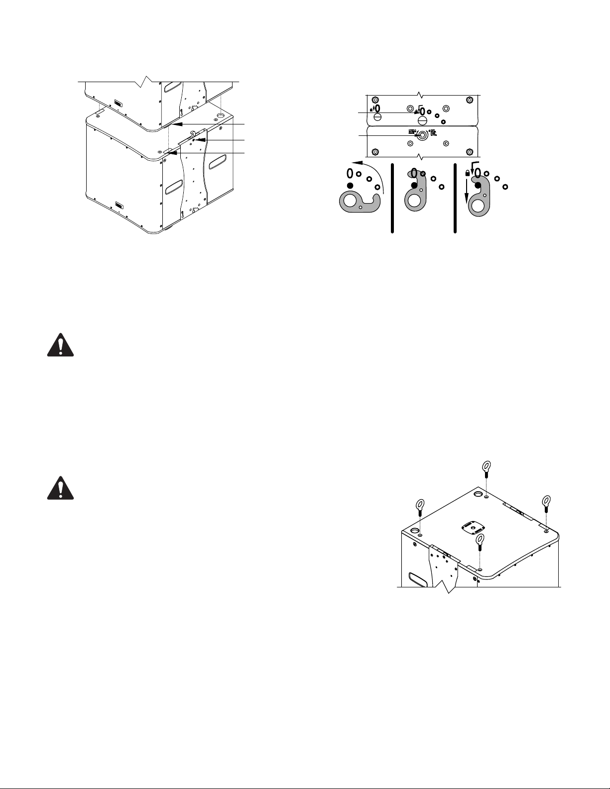
Rigging KLA181 Loudspeakers Together
2
1
3
2
1
Locked
Position
— Figure 1 —
Retracted
Position
Up
Position
— Figure 2 —
1. Insert the supplied 6 mm hex key into the hex socket (Figure 1, 1) and make sure the hex key is rotated completely to the Unlock position.
2. Place a KLA181 on top of the fi rst one with the loudspeakers facing the same direction. Make sure that the four feet (2) on the top KLA181 nest
properly with the four feet receptacles (3) on the top of the bottom KLA181.
NOTE:
The bottom portion of Figure 2 shows the motion of the hook during the latching process. This is not visible on the
actual hardware.
3. Insert the 6 mm hex key into the hex socket (1) in the lower KLA181 and turn the key fully to the Locked Position. Repeat for the other side.
a. In the Retracted Position, you cannot see the hook in the view holes.
b. When the hook reaches the Up Position, the hook almost completely fi lls the large viewing (2) hole at the top.
c. In the fi nal, Locked Position, you can see a small portion of the hook in the bottom of the large viewing hole (2).
Using Integrated Suspension Points
NOTE:
X 1.50, 35 mm – 38 mm) included in the available accessory kit (model number:
KLA181 M10 KIT).
The KLA181 suspension points are designed for use with the eyebolts (M10
1. Use a 6 mm hex key to remove the four hex screws from the four KLA181 M10
installation points on the top of the loudspeaker.
2. Thread an eyebolt (1) into each of the threaded inserts.
3. Tighten the eyebolts until their shoulders are snug against the enclosure.
4. Continue to rotate the eyebolts until they reach the desired position. Do not overtighten.
5. The loudspeakers are ready for suspension.
TD-000335-00-C
2
— Figure 3 —
 Loading...