

Page 1
MODEL SM58
UNIDIRECTIONAL DYNAMIC MICROPHONE
The Shure SM58 is a unidirectional (cardioid) dynamic vocal microphone designed for professonal vocal use in sound reinforcement and studio recording. A highly effective, built-in,
spherical filter minimizes wind and breath “pop” noise. A cardioid pickup pattern isolates the main sound source while minimizing unwanted background noise. The SM58 has a tailored
vocal response for a sound which is a world standard. Rugged
construction, a proven shock mount system, and a steel mesh
grille ensure that even with rough handling, the SM58 will perform consistently. Outdoors or indoors, singing or speech—the
SM58 is the overwhelming choice of professionals worldwide.
Features
S Frequency response tailored for vocals, with brightened
midrange and bass rolloff
S Uniform cardioid pickup pattern isolates the main sound
source and minimizes background noise
S Pneumatic shock-mount system cuts down handling noise
S Effective, built-in spherical wind and pop filter
S Supplied with break-resistant stand adapter w hich r otates 1 80_
S Legendary Shure quality, ruggedness, and reliability
Variations
SM58
SM58S (With On/Off Switch)
PROXIMITY EFFECT
When the sound source is less than 6 mm (1/4 in.) from the
microphone, the microphone b oosts b ass f requencies ( by 6 t o
10 dB at 100 Hz), creating a warmer and richer bass sound
than when f arther a way. T his e ffect, k nown a s p roximity e f fect,
happens only in unidirectional dynamic microphones like the
SM58. The SM58 low-frequency roll-off provides greater control, allowing the u ser t o t ake f ull a dvantage o f p roximity e f fect.
Model SM58 User Guide
APPLICATIONS AND PLACEMENT
The SM58 is ideal for close-up vocals and can be held in the
hand or m ounted o n a s tand. S ome o f t he m ost common a pplications and placement techniques are listed in the following table.
Keep in mind that microphone techni que is largely a matter of
personal taste—there is no one “correct” microphone position.
APPLICATION SUGGESTED MICROPHONE
Lead &
Backup
Vocals
Speech 150 mm (6 in.) to .6 m (2 ft)
PLACEMENT
Lips less than 150 mm (6 in.)
away or touching the windscreen, on axis to mic rophone.
away from mouth, just above
nose height.
200 mm (8 in.) to .6 m (2 ft)
away from mouth, slightly off
to one side.
1 m (3 ft) to 2 m (6 ft) away. Thinner; distant
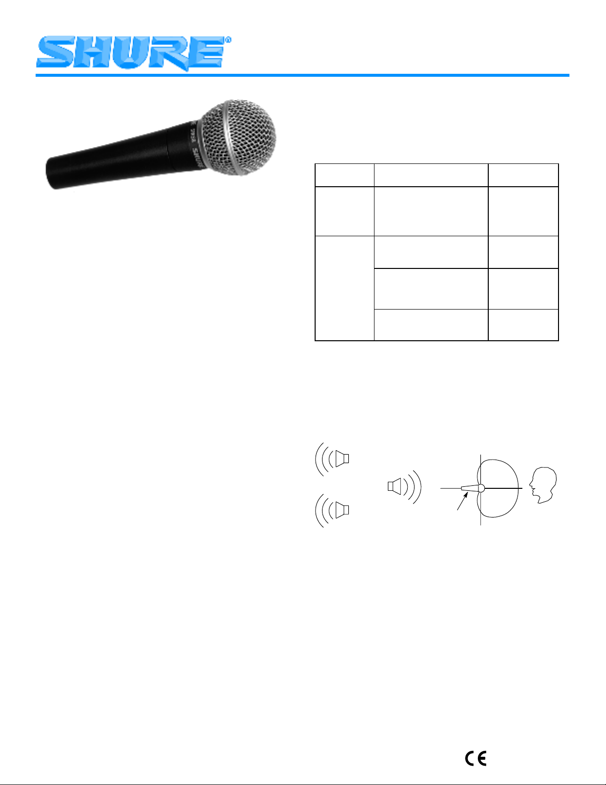
STAGE MONITOR & P.A. LOUDSPEAKER PLACEMENT
Place the stage monitor directly behind the microphone (see
Figure 1). Locate the P.A. loudspeakers so that they point away
from the rear of the microphone. With the speakers located in
these positions, the possibility of feedback is greatly reduced.
Always check the stage setup before a performance to ensure
optimum placement of microphone and monitors.
STAGE
MONITOR
P.A.
LOUDSPEAKERS
180°
MICROPHONE
RECOMMENDED LOUDSPEAKER PLACEMENT
FIGURE 1
GENERAL RULES FOR MICROPHONE USE
1. Aim the microphone toward the desired sound source and
away from unwanted sources.
2. Locate the microphone as close as practical to the desired
sound source.
3. Work close to the microphone for extra bass response.
4. Use only one microphone per sound source.
5. Locate microphones at least three times as far from other
microphones as from the sound source.
6. Use as few microphones as practical.
7. Place microphones far from sound-reflecting surfaces.
8. Add a windscreen when using the microphone outdoors, for
closeup speech, or vocals.
9. Avoid excessive handling to minimize mechanical noise.
TONE QUALITY
Robust sound,
emphasized
bass, maximum
isolation from other sources.
Natural sound,
reduced bass.
Natural sound,
reduced bass
and minimal “s”
sounds.
sound;
ambience.
90°
0°
SOUND
SOURCE
90°
E2002, Shure Incorporated
27A2902 (BH)
Printed in U.S.A.
Page 2

SPECIFICATIONS
Á
Á
Á
Á
Á
Á
Type
Dynamic (moving coil)
Frequency Response
50 to 15,000 Hz (see Figure 2)
TYPICAL FREQUENCY RESPONSE
FIGURE 2
Polar Pattern
Unidirectional (cardioid), rotationally symmetrical about microphone axis, uniform with frequency (see Figure 3)
TYPICAL POLAR PATTERNS
FIGURE 3
Sensitivity (at 1,000 Hz Open Circuit Voltage)
–54.5 dBV/Pa (1.85 mV)
1 Pa = 94 dB SPL
Impedance
Rated impedance is 150 W (300 W actual) for connection to
microphone inputs rated low impedance
Polarity
Positive pressure on diaphragm produces positive voltage on
pin 2 with respect to pin 3
Internal Connections (Figure 4)
SWITCH (SM58S ONLY)
GREEN
YELLOW
CARTRIDGE
CODED TERMINAL
GREEN
YELLOW
TRANSFORMER
BLUE
RED
2
1
3
BLACK
INTERNAL CONNECTIONS
FIGURE 4
Connector
Three-pin professional audio connector (male XLR type)
Case
Dark gray, enamel-painted, die cast metal; matte-finished,
silver colored, spherical steel mesh grille
Overall Dimensions (Figure 5)
162 mm
(6 3/8in.)
51 mm
(2 in.)
23 mm
(29/32in.)
OVERALL DIMENSIONS
FIGURE 5
Swivel Adapter
Positive-action, break-resistant, adjustable through 180°,
5
with standard
/8 in.–27 thread
Net Weight
298 grams (10.5 oz)
CERTIFICATION
Eligible to bear CE Marking. Conforms to European EMC Directive 89/336/EEC. Meets applicable tests and performance
criteria in European Standard EN55103 (1996) parts 1 and 2,
for residential (E1) and light industrial (E2) environments.
FURNISHED ACCESSORIES
Swivel Stand Adapter A25D. . . . . . . . . . . . . . . . . . . . . . . . . . . .
Storage Bag 26A13. . . . . . . . . . . . . . . . . . . . . . . . . . . . . . . . . . .
OPTIONAL ACCESSORIES
Windscreen A58WS Series (8 colors available)
. . . . . . . . . . .
Desk Stand S37A, S39A. . . . . . . . . . . . . . . . . . . . . . . . . . . . .
Isolation Mount A55M. . . . . . . . . . . . . . . . . . . . . . . . . . . . . . . .
Dual Mount A26M. . . . . . . . . . . . . . . . . . . . . . . . . . . . . . . . . . .
Cable (7.6 m [25 ft] C25E, C25F. . . . . . . . . . . . . . . . . . . . . .
REPLACEMENT PARTS
Cartridge R59
. . . . . . . . . . . . . . . . . . . . . . . . . . . . . . . . . . . . .
Screen and Grille Assembly RK143G. . . . . . . . . . . . . . . . . .
For additional service or parts information, please contact
Shure’s Service department at 1-800-516-2525. Outside the
United States, please contact your authorized Shure Service
Center.
2
Page 3

MODÈLE SM58
MICROPHONE DYNAMIQUE UNIDIRECTIONNEL
Le Shure SM58 est un microphone vocal dynamique unidirectionnel (cardioïde) conçu pour la sonorisation et l’enregistrement de la voix. Un filtre sphérique à haute efficacité minimalise
les bruits de vent, de respiration et de bouche. Une configuration cardioïde isole la source sonore principale tout en rédui-
sant les bruits de fond indésirables. La courbe de réponse vo-
cale du SM58 lui confère une sonorité qui est devenue le critère
d’excellence mondial. Une construction robuste, un système
de monture antichocs éprouvé et une grille en acier inoxydable
assurent une fonctionnement sans faille, même dans les conditions les plus rigoureuses. Que ce soit pour la salle ou le plein
air, le chant ou la parole, le SM58 est le choix de prédilection
des professionnels des quatre coins du globe.
Avantages
S Gamme de fréquences adaptée à la voix avec
médiums extra/clairs et limiteur de basses
S Configuration cardioïde uniforme isolant la source
sonore principale et minimalisant le bruit de fond
S Système antichocs pneumatique réduisant la
transmission des bruits de manipulation
S Filtre sphérique efficace contre les bruits de vent
et de bouche
S Adaptateur de pied incassable pivotant sur
180_ inclus
S Qualité et fiabilité légendaires de Shure
Variations
SM58
SM58S (avec interrupteur d’alimentation electrique)
EFFET DE PROXIMITÉ
Lorsque la source sonore se trouve à moins de 6 mm du
microphone, les basses fréquences sont augmentées de 6 à 10
dB, à 100 Hz, produisant un son plus chaud et plus puissant.
Ce phénomène, connu sous le nom d’effet de proximité, est ex-
clusif aux micr o p h o nes dynamiques unidirectionnels tels que le
SM58. L ’atténuation de basses fréquences du SM58 assure un
meilleur contrôle et permet à l’utilisateur de mieux tirer parti de
l’effet de proximité.
APPLICATIONS ET PLACEMENT
Le SM58 est idéal pour la prise de son vocale de près et
peut être tenu à la main ou monté sur pied. Quelques–unes des
applications et techniques de placement les plus courantes
sont expliquées dans le tableau ci-dessous. Ne pas oublier qu e
la technique de placement des micros est surtout une question
de goût personnel et qu’il n’y a pas de position “correcte”.
APPLICATION PLACEMENT SUGGÉRÉ SONORITÉ
Chanteurs et
choristes
Parole 15 à 50 cm de la bouche,
Lèvres à moins de 15 cm ou
touchant le coupe–vent, dans
l’axe du micro.
juste au–dessus de la base
du nez
20 à 50 cm de la bouche
légèrement hors axe
1 à 2 m de distance Petit son, distant,
Son robuste,
basses accentuées, isolation
maximum
d’autres sources
sonores.
Son naturel,
basses réduites
Son naturel,
basses réduites,
sifflements des
“s” minimum
ambiance.
DISPOSITION DES RETOURS DE SCÈNE ET DES
HAUTS-PARLEURS DE SONORISATION
Placer le retour d i r e c t e m e n t d e r r i ère le microphone (voir la
figure 1). Disposer les hauts-parleurs de sonorisation de manière à ce qu’ils soient tournés à l’opposé de l’arrière du micro-
phone pour réduire au maximum les risques de Larsen. Tou-
jours vérifier la mise en place de la scène pour s’assurer que
la disposition des microphones et haut-parleurs est optimale.
90°
RETOUR
HAUT–
PARLEURS
PLACEMENT RECOMMANDÉ POUR LES HAUT–PARLEURS
180°
MICROPHONE
90°
FIGURE 1
0°
SOURCE
SONORE
RÈGLES GÉNÉRALES D’UTILISATION DE
MICROPHONES
1. Diriger le micro vers la source sonore, le plus à l’écart pos-
sible des bruits indésirables.
2. Placer le microphone aussi près que possible de la source
sonore.
3. Plus la source sonore est proche du micro, plus les basses
sont présentes.
4. N’utiliser qu’un microphone par source sonore.
5. La distance entre les microphones doit être d’au moins
trois fois celle de chaque micro à sa source sonore respec-
tive.
6. Utiliser le moins de microphones possible.
7. Placer les microphones aussi loin que possible des surfa-
ces réfléchissantes.
8. Utiliser un coupe-vent si les microphones sont utilisés à
l’extérieur.
9. Éviter les manipulations inutiles pour minimiser le cap-
tage des bruits mécaniques.
3
Page 4
CARACTÉRISTIQUES
Type
Dynamique (à bobine mobile)
Courbe de réponse
50 à 15 000 Hz (voir la figure 2)
Connecteur
Connecteur professionnel 3 broches (mâle, type XLR)
Corps
Acier moulé émaillé gris foncé avec grille sphérique en acier
argent mat
Dimensions hors tout (voir la figure 5)
162 mm
3
(6
/8in.)
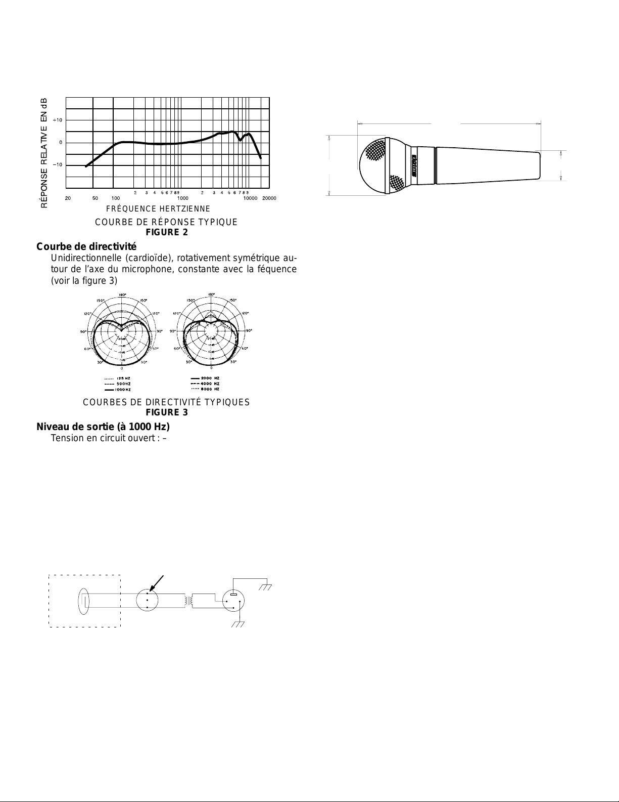
FRÉQUENCE HERTZIENNE
COURBE DE RÉPONSE TYPIQUE
FIGURE 2
Courbe de directivité
Unidirectionnelle (cardioïde), rotativement symétrique autour de l’axe du microphone, constante avec la féquence
(voir la figure 3)
COURBES DE DIRECTIVITÉ TYPIQUES
FIGURE 3
Niveau de sortie (à 1000 Hz)
Tension en circuit ouvert : –54,5 dBV/Pa (1,85 mV)
1 Pa = 94 dB SPL
Impédance
L’impédance nominale est de 150 W (300 W réelle) pour
connexion aux entrées de micros basse impédance
Phase
Une pression positive sur le diaphragme produit une tension
positive sur la broche 2 par rapport à la broche 3
Connexions internes (voir la figure 4)
CARTOUCHE
COMMUTATEUR
(SM58S SELULEMENT)
VERT
JAUNE
CODÉE
GREEN
JAUNE
BLEU
ROUGE
2
1
3
NOIR
51 mm
(2 in.)
23 mm
29
/32in.)
(
DIMENSIONS HORS TOUT
FIGURE 5
Adaptateur de pied pivotant
À emboîtement, incassable, réglable de 0 à 180_ avec filet
standard de 5/8”–27
Poids net
298 grammes
Homologation
Autorisé à porter la marque CE. Conforme à la directive
CEM européenne 89/336/CEE. Conforme aux critères applicables de test et de performances de la norme européenne EN
55103 (1996) parties 1 et 2 pour les environnements résiden-
tiels (E1) et d’industrie légère (E2).
ACCESSOIRES FOURNIS
Adaptateur de pied pivotant A25D. . . . . . . . . . . . . . . . . . . . . .
Étui de rangement 26A13. . . . . . . . . . . . . . . . . . . . . . . . . . . . .
ACCESSOIRES EN OPTION
Coupe-vent Série A58WS (8 couleurs disponibles). . . . . . . .
Support de table S37A, S39A. . . . . . . . . . . . . . . . . . . . . . . . .
Monture isolante A55M. . . . . . . . . . . . . . . . . . . . . . . . . . . . . . .
Double monture A26M. . . . . . . . . . . . . . . . . . . . . . . . . . . . . . . .
Câble de 7,6 m C25E, C25F. . . . . . . . . . . . . . . . . . . . . . . . . .
PIÈCES DE RECHANGE
Cartouche R59. . . . . . . . . . . . . . . . . . . . . . . . . . . . . . . . . . . . . .
Ensemble grille et coupe–vent RK143G. . . . . . . . . . . . . . . .
Pour des informations plus détaillées sur les réparations ou
les pièces de rechange, contacter le service après–vente de
Shure, au 1–800–516–2525. Hors des États–Unis contacter
le centre de réparations agréé de Shure.
TRANSFORMATEUR
CONNEXIONS INTERNES
FIGURE 4
4
Page 5

MODELL SM58
UNIDIREKTIONALES DYNAMISCHES MIKROPHON
Beim Shure SM58 handelt es sich um ein unidirektionales
dynamisches (Nieren–) Gesangsmikrophon, das für
professionelle Tonverstärkung und Tonstudioaufnahmen entwickelt wurde. Ein eingebauter, hochwirksamer sphärischer
Filter minimiert Windgeräusche und Popplaute-
Geräusche. Die Nieren-Aufnahmecharakteristik isoliert die
Haupttonquelle und reduziert zugleich unerwünschte Hintergrundgeräusche auf ein Minimum. Der Frequenzgang des
SM58 wurde speziell auf Gesangsstimmen abgestimmt, wodurch es zu den weltweit führendon Mikrophonen gehört. Die
robuste Ausführung, ein bewährtes Dämpfer–System und ein
Stahlgittergrill stellen sicher, d a ß das SM58 auch bei rauher Be-
handlung mit unveränderlicher Zuverlässigkeit funktioniert. Sei
es im Freien oder in Räumen, für Gesang oder Sprache—welt-
weit entscheiden sich immer mehr Profis für das SM58.
Merkmale
S Auf Gesangsaufnahmen zugeschnittener Frequenzgang,
mit aufgehelltem Mittenbereich und Baßdämpfung
S Gleichförmige Nieren-Aufnahmecharakteristik isoliert die
Haupttonquelle und reduziert zugleich Hintergrundgeräu-
sche auf ein Minimum
S Pneumatisches Dämpfer-System verringert Handha-
bungsgeräusche
S Wirksamer, eingebauter sphärischer Wind- und Poppfilter
S Mit einem bruchfesten, um 180_ drehbaren Stativadapter
ausgestattet
S Bewährte Shure Qualität, Robustheit und Zuverlässigkeit
Variations
SM58
SM58S (mit netz [power] ein/aus-knopf)
NAHBESPRECHUNGSEFFEKT
Wenn die T onquelle weniger als 6 mm vom Mikrophon entfernt ist, verstärkt das Mikrophon Baßfrequenzen (um 6 bis 10
dB bei 100 Hz), wodurch ein wärmerer und reicherer Baßklang
als bei größeren Entfernungen erzeugt wird. Dieser Effekt, der
als Nahbesprechungseffekt bezeichnet wird, tritt nur bei unidirektionalen dynamischen Mikrophonen wie dem SM58 auf.
Das allmähliche Dämpfungsverhalten des SM58 bei niedrigen
Frequenzen bietet eine bessere Regelung und ermöglicht dem
Benutzer, den Nahbesprechungseffekt voll auszunutzen.
ANWENDUNG UND AUFSTELLUNG
Das SM58 ist ideal für Nahaufnahmen von Gesang und
kann mit der Hand gehalten oder an einem Stativ angebracht
werden. Einige der gebräuchlichsten Anwendungen und Aufstellungsverfahren für das SM57 sind in der nachfolgenden Ta-
belle aufgeführt. Beachten Sie bitte, daß der Mikrophoneinsatz
weitgehend eine “Geschmackssache“ ist – von “richtigen“ oder
“falschen“ Mikrophonpositionen kann hier also nicht die Rede
sein.
ANWENDUNG
Haupt- und
Hintergrundsänger
Sprache 15 bis 50 cm Abstand vom
EMPFOHLENE MIKROPHONAUFSTELLUNG
Weniger als 15 cm Abstand
vom Mund oder Berührung
des Windschalterfilter, axial
zum Mikrophon.
Mund, etwas oberhalb der Nasenhöhe.
20 bis 50 cm Abstand vom
Mund, etwas zur Seite geneigt.
1 bis 2 m Abstand. Dünnerer, ent-
TONQUALITÄT
Robuster Klang,
hervorgehobener
Baß, maximale
Isolierung von anderen Quellen.
Natürlicher Klang,
reduzierter Baß.
Natürlicher Klang,
reduzierter Baß
und minimale
Zischlaute.
fernterer Klang;
Umgebungsgeräusche.
AUFSTELLUNG DER BÜHNENLAUTSPRECHER UND
LAUTSPRECHER FÜR BESCHALLUNGSANLAGE
Den Bühnenlautsprecher direkt hinter dem Mikrophon aufstellen (siehe Abbildung 1). Die Lautsprecher der Beschallungsanlage so plazieren, daß sie von der Rückseite des Mikrophons wegzeigen. Wenn sich die Lautsprecher an diesen
Stellen befinden, wird das Risiko von Rückkopplungen stark reduziert. Vor einem Auftritt stets die Bühnenausstattung über-
prüfen, um eine optimale Aufstellung der Mikrophone und Lautsprecher sicherzustellen.
BÜHNEN-
LAUTSPRECHER
180°
LAUTSPRECHER
DER BESCHALLUNGSANLAGE
EMPFOHLENE LAUTSPRECHERAUFSTELLUNG
MIKROPHON
ABBILDUNG 1
90°
0°
TONQUELLE
90°
ALLGEMEINE REGELN FÜR DEN MIKROPHONGE-
BRAUCH
1. Das Mikrophon auf die gewünschte Tonquelle und weg
von unerwünschten Quellen richten.
2. Das Mikrophon so nahe wie möglich an die gewünschte
Tonquelle heranbringen.
3. Abstand verringern, wenn zusätzliches Baßverhalten
gewünscht wird.
4. Je Tonquelle nur ein Mikrophon verwenden.
5. Die Mikrophone mindestens dreimal so weit von einan-
der entfernt aufstellen wie von der Tonquelle.
6. So wenig Mikrophone wie möglich verwenden.
7. Mikrophone weit entfernt von Akustikflächen anbringen.
8. Einen Windschirm anbringen, wenn das Mikrophon im
Freien verwendet wird; das gilt sowohl für Sprach– als
auch für Gesangsaufnahmen.
9. Mikrophone s o wenig wie möglich anfassen, um mecha-
nische Geräusche zu vermeiden.
5
Page 6

SPEZIFIKATIONEN
Typ
Dynamisch (Tauchspule)
Frequenzgang
50 bis 15.000 Hz (siehe Abbildung 2)
Stecker
Dreipoliger Profi-XLR-stecker
Gehäuse
Dunkelgraues einbrennlackiertes Druckgußmetall, kugel-
förmiger, silberfarbener Stahlgittergrill in matter Ausfüh-
rung
Gesamtabmessungen
162 mm
3
(6
/8in.)
FREQUENZ IN Hz
TYPISCHER FREQUENZGANG
ABBILDUNG 2
Polarcharakteristik
Unidirektionale (Nieren–) Charakteristik, rotationssymmetrisch um Mikrophonachse, gleichförmig mit Frequenz (siehe Abbildung 3)
TYPISCHE POLARCHARAKTERISTIK
ABBILDUNG 3
Ausgangspegel (bei 1000 Hz)
Leerlaufspannung: –54,5 dBV/Pa (1,85 mV)
1 Pa = 94 dB SPL
Impedanz
Die Nennimpedanz für den Anschluß an niederohmige Mikrophoneingänge beträgt 150 W (Ist–Wert 300 W).
Phasenabgleich
Positiver Druck auf die Membran erzeugt positive Spannung an Stift 2 gegenüber Stift 3.
Interne Schaltungen
SCHALTER (SM58S EINZIG)
GRÜN
GELB
KAPSEL
GEKENNZEICHNET
GELB
BLAU
ROT
GRÜN
KRAFTTRANSFORMATOR
INTERNE SCHALTUNGEN
ABBILDUNG 4
12
3
SCHWARZ
51 mm
(2 in.)
23 mm
29
/32in.)
(
GESAMTABMESSUNGEN
ABBILDUNG 5
Schwenkadapter
Formschlüssig, bruchfest, bis 180_ verstellbar, mit 5/8
Inch-27 Standardgewinde
Nettogewicht
298 Gramm
ZERTIFIZIERUNG
Zur CE–Kennzeichnung berechtigt. Entspricht der EU–
Richtlinie über elektromagnetische Verträglichkeit
89/336/EEC. Erfüllt die Prüfungs– und Leistungskriterien der
europäischen Norm EN 55103 (1996) Teil 1 und 2 für Wohngebiete (E1) und Leichtindustriegebiete (E2).
MITGELIEFERTES ZUBEHÖR
Schwenkstativadapter A25D. . . . . . . . . . . . . . . . . . . . . . . . . . .
Tasche 26A13. . . . . . . . . . . . . . . . . . . . . . . . . . . . . . . . . . . . . . .
SONDERZUBEHÖR
Windschalterfilter Serie A58WS (in 8 Farben erhältlich). . . .
Tischstativ S37A, S39A. . . . . . . . . . . . . . . . . . . . . . . . . . . . . . .
Isolierbefestigung A55M. . . . . . . . . . . . . . . . . . . . . . . . . . . . . .
Doppelbefestigung A26M. . . . . . . . . . . . . . . . . . . . . . . . . . . . .
Kabel (7,6 m) C25E, C25F. . . . . . . . . . . . . . . . . . . . . . . . . . . .
ERSATZTEILE
Kapsel R59. . . . . . . . . . . . . . . . . . . . . . . . . . . . . . . . . . . . . . . . .
Schirm– und Grill–Baugruppe RK143G. . . . . . . . . . . . . . . . .
Weitere Informationen über Service oder Ersatzteile erhalten Sie von der Shure Kundendienstabteilung unter der Telefonnummer 1–800–516–2525. Außerhalb der Vereinigten
Staaten wenden Sie sich bitte an Ihr Shure Vertragskundendienstzentrum.
6
Page 7

MODELO SM58
MICROFONO DINAMICO UNIDIRECCIONAL
El Shure SM58 es un micrófono dinámico unidireccional
(cardioide) diseñado para vocalistas profesionales en situacio-
nes de refuerzo de sonido y grabaciones en estudio. Su filtro
esférico incorporado altamente eficaz reduce al mínimo los ruidos causados por el viento y por el aliento. El dispersión polar
de cardioide aísla la fuente sonora principal a la vez que reduce
al mínimo los ruidos de fondo. El SM58 tiene una respuesta
ajustada para la captación de voces que produce una calidad
de sonido que se ha convertido en la norma a nivel mundial. Su
fabricación resistente, su comprobado sistema de montaje resistente a choques y su rejilla de malla de acero garantizan que
aún en condiciones de mal trato al aparato, el SM58 dará un
rendimiento consistente. Ya sea a la intemperie o bajo techo,
para cantantes o para oradores—el SM58 es la elección de la
gran mayoría de los profesionales del mundo entero.
USO COLOCACION SUGERIDA
Voces principales y de
fondo
Conferencias De 15 a 50 cm de la boca,
DEL MICROFONO
Los labios a no más de 15 cm
o tocando al paravientos, en
línea con el eje de captación
del micrófono.
justo arriba del nivel de la nariz.
De 20 a 50 cm de la boca, ligeramente a un lado de ésta.
De 1 a 2 m de distancia. Sonido más agu-
CALIDAD DEL
TONO
Sonido robusto,
frecuencias bajas
enfatizadas, aislamiento máximo
de otras fuentes
sonoras.
Sonido natural,
frecuencias bajas
reducidas.
Sonido natural,
frecuencias bajas
reducidas y pocos sonidos sibilantes.
do y distante; sonido ambiental.
Características
• Respuesta de frecuencia diseñada para la voz humana
con aumento de frecuencias medias y atenuación progre-
siva de bajas frecuencias
• La dispersión p olar cardioide uniforme aisla la fuente sonora
principal a la vez que reduce al mínimo los ruidos de fondo
• El sistema de montaje neumático resistente a choques re-
duce los ruidos causados por el manejo
• Filtro esférico incorporado altamente eficaz para reducir
los ruidos causados por el viento y por el aliento
• Incluye un adaptador de pedestal resistente a las roturas
que gira 180_
• La legendaria calidad, robustez y fiabilidad de Shure
Variaciones
SM58
SM58S (con interruptor de encendido)
EFECTO DE PROXIMIDAD
Cuando la fuente sonora se encuentra a menos de 6 mm
del micrófono, éste introduce un aumento progresivo en las frecuencias bajas (de 6 a 10 dB a 100 Hz) que crea un sonido de
frecuencias bajas más cálido y fuerte que cuando la fuente está
más alejada. Este efecto, conocido como el efecto de proximidad, se produce únicamente en micrófonos dinámicos unidireccionales tales como el SM58. La atenuación progresiva de
frecuencias bajas que incorpora el SM58 ofrece mayor control
sobre el sonido y ayuda al usuario a aprovechar el efecto de
proximidad.
USOS Y COLOCACION
El SM58 es ideal para captar voces a corta distancia y puede sostenerse en la mano o en un pie. Algunas de las técnicas
más comunes de uso y colocación se indican en la tabla siguiente. Recuerde que la técnica de uso de los micrófonos es
en gran parte cuestión de gusto personal—no existe una
posición de micrófono que sea la ”correcta”.
COLOCACION DE ALT AVOCES DE PA MONITOR DE
ESCENARIO
Coloque el monitor de escenario directamente detrás del
micrófono (vea la Figura 1). Coloque los altavoces de P.A. de
manera que el sonido que emiten se aleje de la parte trasera
del micrófono. Cuando los altavoces se colocan en estas posiciones, la posibilidad realimentación se reduce significativamente. Siempre compruebe la disposición del escenario antes
de una actuación para verificar que la colocación del micrófono
y los monitores es la óptima.
MONITOR DE
ESCENARIO
AL TAVOCES
DE P.A .
COLOCACION RECOMENDADA DE LOS ALTAVOCES
180°
MICROFONO
FIGURA 1
90°
0°
FUENTE
SONORA
90°
REGLAS GENERALES DE USO DE MICROFONOS
1. Apunte el micrófono hacia la fuente sonora deseada y ale-
jado de las fuentes no deseadas.
2. Coloque el micrófono lo más cerca posible a la fuente so-
nora deseada.
3. Acérquese al micrófono para obtener mayor respuesta de
frecuencias bajas.
4. Utilice sólo un micrófono para captar una fuente sonora.
5. La distancia entre un micrófono y otro deberá ser al menos
tres veces la distancia de cada fuente a su micrófono.
6. Utilice el menor número de micrófonos que resulte prácti-
co.
7. Aleje los micrófonos lo más posible de las superficies re-
flectoras.
8. Instale un paravientos si se usa el micrófono a la intempe-
rie, o al captar una voz a muy poca distancia.
9. Evite el manejo excesivo para reducir la captación de rui-
dos mecánicos.
7
Page 8

ESPECIFICACIONES
Tipo
Dinámico (bobina móvil)
Respuesta de frecuencia
50 a 15.000 Hz (vea la Figura 2)
Conector
Conector de audio de tres patillas profesional (tipo XLR
macho)
Caja
Metal fundido a troquel esmaltado de color gris oscuro con
rejilla esférica de acero con acabado mate de color platea-
do
Dimensiones totales
162 mm
(6 3/8in.)
FRECUENCIA EN Hz
RESPUESTA DE FRECUENCIA TIPICA
FIGURA 2
Dispersión polar
Unidireccional (cardioide), simétrico respecto al eje del micrófono, uniforme respecto a la frecuencia
(vea la Figura 3)
DISPERSIONES POLAR TIPICAS
FIGURA 3
Nivel de salida (a 1.000 Hz)
Voltaje de circuito abierto: –54,5 dBV/Pa (1,85 mV)
1 Pa = 94 dB SPL
Impedancia
La impedancia nominal es de 150 W (real: 300 W) para conexión a entradas de micrófono de baja impedancia.
Fase
Una presión positiva en el diafragma del micrófono produce una tensión positivo en la patilla 2 con respecto a la patilla 3
Conexiones internas
INTERRUPTOR
(SM58S SOLO)
VERDE
AMARILLO
CAPSULA
CODIF
VERDE
AMARILLO
TRANFORMADOR
AZUL
ROJO
2
1
3
NEGRO
CONEXIONES INTERNAS
FIGURA 4
51 mm
(2 in.)
23 mm
(29/32in.)
DIMENSIONES TOTALES
FIGURA 5
Adaptador giratorio
De acción positiva, resistente a roturas, 180_ de ajuste con
rosca estándar de 5/8 pulg–27
Peso neto
298 g (10,5 oz)
CERTIFICACIONES
Califica para llevar las marcas CE. Cumple la directiva europea 89/336/EEC de compatibilidad electromagnética. Se
ajusta a los criterios correspondientes de verificación y funcio-
namiento establecidos en la norma europea EN 55103 (1996),
partes 1 y 2, para zonas residenciales (E1) y zonas de industria
ligera (E2).
ACCESORIOS SUMINISTRADOS
Adaptador giratorio A25D. . . . . . . . . . . . . . . . . . . . . . . . . . . . .
Bolsa de almacenamiento 26A13. . . . . . . . . . . . . . . . . . . . . .
ACCESORIOS OPCIONALES
Paravientos Serie A58WS (disponible en 8 colores). . . . . . .
Pie de sombremesa S37A, S39A. . . . . . . . . . . . . . . . . . . . . .
Montaje con aislamiento A55M. . . . . . . . . . . . . . . . . . . . . . . . .
Montaje doble A26M. . . . . . . . . . . . . . . . . . . . . . . . . . . . . . . . . .
Cable (7,6 m [25 pies]) C25E, C25F. . . . . . . . . . . . . . . . . . . .
REPUESTOS
Cartucho R59. . . . . . . . . . . . . . . . . . . . . . . . . . . . . . . . . . . . . . .
Conjunto de malla y rejilla RK143G. . . . . . . . . . . . . . . . . . . .
Para información adicional acerca del servicio o repuestos, llame al Departamento de servicio Shure al teléfono
1–800–516–2525. Fuera de los EE.UU., llame al servicentro
autorizado de productos Shure.
8
Page 9

MODELLO SM58
MICROFONO DINAMICO UNIDIREZIONALE
Il modello SM58 della Shure è un microfono dinamico unidirezionale (cardioide) per applicazioni vocali realizzato per
l’utilizzo in studi di registrazione ed impianti di amplificazione
professionali. Un filtro sferico incorporato molto efficace riduce
al minimo il rumore del vento e l’effeto pop. Il diagramma polare
a cardioide isola la sorgente sonora principale e simultaneamente riduce al minimo il rumore di fondo indesiderato. Il microfono SM58 presenta una risposta vocale ottimizzata per a fornire un suono la cui qualità costituisce uno standard mondiale. La
robustezza della fabbricazione, il comprovato sistema di supporto antivibrazione e la griglia in acciaio inossidabile ne garantiscono la costanza delle prestazioni, anche quando lo si maneggia senza delicatezza. Sia all’aperto che in interni, per canto
od o parlato — l’ SM58 è, a schiacciante maggioranza, il microfono scelto dai professionisti in tutto il mondo.
Caratteristiche
• Risposta in frequenza ottimizzata per applicazioni vocali,
con maggiore chiarezza alle frequenze intermedie e atte-
nuazione alle basse frequenze.
• Diagramma polare a cardioide uniforme, che isola la sor-
gente sonora principale e riduce al minimo il rumore di fon-
do.
• Sistema pneumatico di supporto antivibrazione che riduce
il rumore derivante dal maneggiamento.
• Efficace filtro sferico incorporato, antipop e antivento.
• Include un adattatore per supporto, resistente a rotture ac-
cidentali, orientabile a 180_.
• Le leggendarie qualità, robustezza e affidabilità Shure.
Variaziones
SM58
SM58S (con interruttore di alimentazione ON/OFF)
EFFETTO DI PROSSIMITÀ
Quando la sorgente sonora si trova a meno di 6 mm di distanza dal microfono, la risposta alle basse frequenze aumenta
progressivamente (da 6 a 10 dB a 100 Hz), generando un suono dei toni bassi più ricco e caldo rispetto a distanze maggiori
della sorgente stessa dal microfono. Questo fenomeno, noto
come effetto di prossimità, si verifica solo in microfoni dinamici
unidirezionali come il modello SM58. L’attenuazione alle basse
frequenze dell’SM58 fornisce un controllo maggiore e consente
a chi usa il microfono di sfruttare pienamente l’effetto di prossimità.
APPLICAZIONI E COLLOCAZIONE
Il modello SM58, ideale per applicazioni vocali a distanza
ravvicinata, può essere tenuto in mano o montato su un supporto. La tabella che segue ne riporta le più comuni applicazioni e
tecniche di collocazione. Rammentare sempre che le tecniche
microfoniche dipendono largamente dalle preferenze personali
e che non esiste una unica posizione ”giusta” del microfono.
APPLICAZIO-NECOLLOCAZIONE DEL MI-
Cantanti e
coro
Parlato Distanza dalle bocca compre-
CROFONO SUGGERITA
Bocca a meno di 15 cm dal
microfono o a contatto con la
griglia, lungo l’asse del microfono.
sa tra 15 e 50 cm, ad un’altezza appena superiore a quella
del naso.
Distanza dalle bocca compresa tra 20 e 50 cm, leggermente fuori asse sull’uno o
l’altro lato.
Distanza compresa tra 1 e 2m.Suono lontano e
QUALITÀ DEI
TONI
Suono robusto,
enfasi sui toni
bassi, massimo
isolamento da
altre sorgenti.
Suono naturale,
toni bassi ridotti.
Suono naturale,
toni bassi ridotti e
suoni sibilanti ridotti al minimo.
sfumato; rumore
ambientale.
COLLOCAZIONE DEGLI ALTOPARLANTI PER IL
PUBBLICO E DEL MONITOR DI PALCO
Collocare l’altoparlante di controllo del palcoscenico direttamente dietro il microfono (vedi Figura 1). Collocare gli altoparlanti per il pubblico in modo che siano rivolti in direzione opposta rispetto alla parte posteriore del microfono. Con tale
disposizione degli altoparlanti si riduce enormemente la possibilità di feedback. Prima della rappresentazione, controllare
sempre l’allestimento del palcoscenico per verificare la collocazione ottimale del microfono e degli altoparlanti di controllo.
MONITOR DI
CONTROLLO
180°
ALTOPARLANTI PER IL
PUBBLICO
COLLOCAZIONE SUGGERITA DEGLI ALTOPARLANTI
MICROFONO
FIGURA 1
90°
0°
SORGENTE
SONORA
90°
REGOLE GENERALI PER L ’USO DEL MICROFONO
1. Rivolgere il microfono verso la sorgente sonora desiderata
e lontano da sorgenti indesiderate.
2. Collocare il microfono quanto più vicino possibile alla sor-
gente sonora desiderata.
3. Per ottenere una maggiore risposta ai toni bassi, tenere il
microfono vicino a bocca.
4. Usare solo un microfono per ciascuna sorgente sonora.
5. Mantenere la d i s t a n z a t r a p i ù microfoni ad un valore uguale
ad almeno tre volte la distanza tra ciascun microfono e la
sorgente sonora.
6. Usare il numero minimo di microfoni consentito dall’appli-
cazione.
7. Collocare i microfoni quanto più lontano possibile da super-
fici fonoriflettenti.
8. Quando si usa il microfono all’aperto, per cantanti od orato-
ri a distanza ravvicinata, utilizzare uno schermo antivento.
9. Evitare movimenti eccessivi del microfono, per ridurre il ru-
more di maneggiamento.
9
Page 10

DATI TECNICI
Tipo
Dinamico (a bobina mobile)
Risposta in frequenza
Da 50 a 15.000 Hz (vedi Figura 2)
Connettore
Connettore audio professionale a tre piedini (tipo XLR ma-
schio).
Contenitore
Corpo in metallo pressofuso, grigio scuro, smaltato; griglia
sferica in acciaio inossidabile, colore argento con finitura
opaca.
Dimensioni totali
162 mm
(6 3/8in.)
FREQUENZA, Hz
RISPOSTA IN FREQUENZA TIPICA
FIGURA 2
Diagramma polare
Unidirezionale (cardioide) con simmetria rotazionale rispetto all’asse del microfono, uniforme con la frequenza
(vedi Figura 3).
DIAGRAMMI POLARI TIPICI
FIGURA 3
Livelli di uscita (a 1.000 Hz)
Tensione a circuito aperto: –54,5 dBV/Pa (1,85 mV)
1 Pa = 94 dB SPL
Impedenza
Valore nominale: 150 W (300 W effettivi) per il collegamento a ingressi microfonici con bassi valori nominali di
impedenza.
Relazione di fase
Una pressione positiva sul diaframma produce una tensione positiva al piedino 2 rispetto al piedino 3.
Collegamenti interni
INTERRUTORE
(SM58S SOLO)
CARTUCCIA
CODICE
51 mm
(2 in.)
23 mm
(29/32in.)
DIMENSIONI TOTALI
FIGURA 5
Adattatore regolabile
Senza slittamento, resistente a sollecitazioni da rottura, re-
golabile in un angolo di 180_, con filettatura standard
5/8” – 27.
Peso netto
298 g
CERTIFICAZIONI
Contrassegnabile con il marchio CE. Conforme alla direttiva europea sulla compatibilità elettromagnetica
89/336/CEE. Conforme ai criteri sulle prestazioni e alle prove pertinenti specificati nella norma europea EN 55103
(1996) parti 1 e 2, per ambienti residenziali (E1) e industriali
leggeri (E2).
ACCESSORI IN DOTAZIONE
Adattatore regolabile A25D. . . . . . . . . . . . . . . . . . . . . . . . . .
Borsa 26A13. . . . . . . . . . . . . . . . . . . . . . . . . . . . . . . . . . . . . .
OPTIONAL
Schermo antivento Serie A58WS (disponibile in 8 colori).
Base da tavolo S37A, S39A. . . . . . . . . . . . . . . . . . . . . . . . .
Adattore antivibrazioni A55M. . . . . . . . . . . . . . . . . . . . . . . .
Adattore doppio A26M. . . . . . . . . . . . . . . . . . . . . . . . . . . . .
Cavo (7,6 m) C25E, C25F. . . . . . . . . . . . . . . . . . . . . . . . . . .
RICAMBI
Cartuccia R59. . . . . . . . . . . . . . . . . . . . . . . . . . . . . . . . . . . . .
Gruppo griglia e schermo RK143G. . . . . . . . . . . . . . . . . . .
Per ulteriori informazioni sui ricambi o per assistenza, chiamare l’assistenza clienti della Shure al numero verde
1–880–516–2525 (solo negli Stati Uniti). Fuori dagli Stati Uniti
rivolgersi al rivenditore o ad un centro di assistenza autorizzato.
VERDE
GIALLO
VERDE
GIALLO
TRANSFORMATORE
COLLEGAMENTI INTERNI
FIGURA 4
BLU
ROSSO
1
2
3
NERO
10
Page 11

11
Page 12

A25D
12
SHURE Incorporated Web Address: http://www.shure.com
222 Hartrey Avenue, Evanston, IL 60202–3696, U.S.A.
Phone: 847-866–2200 Fax: 847-866-2279
In Europe, Phone: 49-7131-72140 Fax: 49-7131-721414
In Asia, Phone: 852-2893-4290 Fax: 852-2893-4055
Elsewhere, Phone: 847-866–2200 Fax: 847-866-2585
 Loading...