


1675 MacArthur Blvd., Costa Mesa, CA, 92626 USA
Main Number (714) 754-6175 or toll free (USA only) (800) 854-4079
Customer Service(714) 957-7150 or toll free (USA only) (800) 772-2834
HPR SUS KIT 122 User Manual
This suspension kit is required for horizontal suspension of the QSC HPR122i from a solid structure or for the vertical suspension of the QSC HPR122i,
HPR152i or HPR153i from a solid structure.
Contents:
•Bar, pull-back, black, PB122i, 1 each
•Gasket, adhesive-backed, 2 each
•Eyebolt, M10, steel, 3 each
•Screw, buttonhead, hex drive, M10-1.5x45mm, 1 each
•Spacer, aluminum, 2 each
•Spring washer, conical, M10, steel, 2 each
•Hex nut, M10-1.5, steel, 1 each
•Lock washer, spring, M10, steel, 2 each
•Flat washer, M10, steel, 2 each
Important Safety Precautions & Explanation of Symbols
Install in accordance with QSC Audio Product's instructions and under the supervision of a licensed Professional Engineer.
WARNING! The exclamation point within an equilateral triangle is intended to alert the user to the presence of important operating
and maintenance (servicing) instructions in this manual.
•Before placing, installing, rigging, or suspending any speaker pro duct, inspect all hardware, suspension,
enclosures, transducers, brackets and associated equipment for damage. Any missing, corroded, deformed, or
non-load rated component could significantly reduce the strength of the installation or placement. Any such
condition severely reduces the safety of the installation and should be immediately corrected. Use only hardware which is rated for the loading conditions of the installation and any possible short-term, unexpected
overloading. Never exceed the rating of the hardware or equipment.
•Consult a licensed, Professional Engineer regarding physical equipment installation. All local, state and
national regulations regarding the safety and operation of equipment are understood and adhered to.
•Use only load rated hardware to attach to the eyebolts or pull-back bar when suspending these products.
•Do not suspend these products from any structural elem ent on the enclosure other than the load rated M10
suspension points.
•Do not suspend the HPR152i or HPR153i horizontally under any circumstances using this or any other hardware.
Vertical Suspension of the HPR122i
Install Two Top-surface Eyebolts
1- Remove the factory installed M10 flat-head screws from the top of the enclosure using a 6mm
hex wrench.
2- Thread an eyebolt into each of the enclosure’s threaded inserts; do not use flat washers or
standoffs on the top eyebolts. Tighten eyebolts.
Install One Pull-back Eyebolt
At the rear of the enclosure, just below the amplifier module, is a M10 flat-head screw which must
be removed and have an eyebolt installed in its place (6mm hex wrench needed).
1- Remove the factory installed M10 flat-head screw from the enclosure using a 6mm hex wrench.
2- Thread an eyebolt into the enclosure’s threaded insert; do not use a flat washer or standoff on
the pull-back eyebolt. Tighten eyebolt.
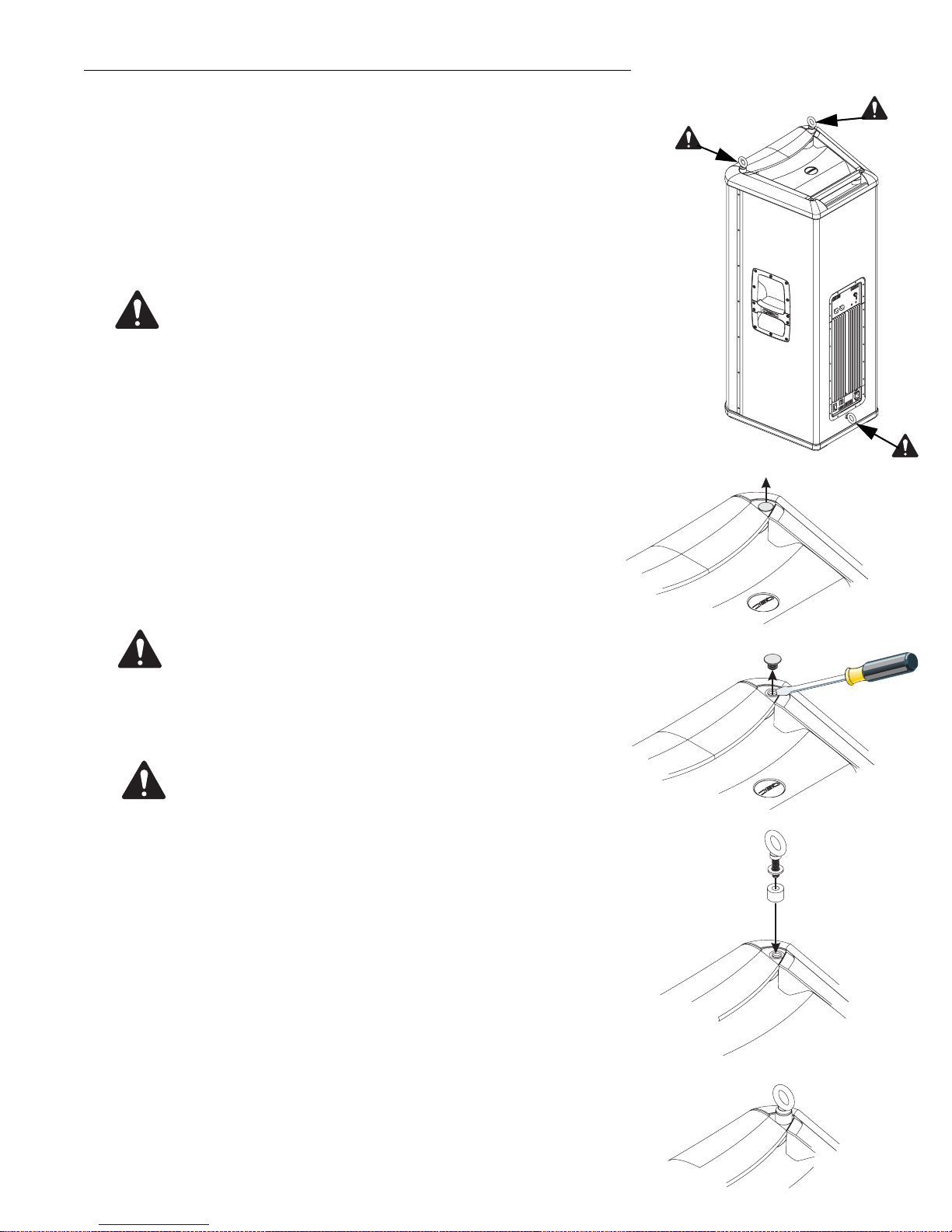
Eyebolt installation locations for vertical suspension
of the HPR122i loudspeaker.
•Do not use the eyebolt standoffs, flat washers, or pull-back bar
when suspending the HPR122i loudspeaker vertically.
•Note! Be sure to tighten each eyebolt until shoulder is snug
against the enclosure. Tighten the eyebolts down and then continue to rotate until they are positioned as desired.
Vertical Suspension of the HPR152i and HPR153i loudspeakers
Install Two Top Surface Eyebolts
1- On the top front corners of the enclosure, locate the rubber
inserts which protect the enclosure’s threads. Remove the rubber
inserts.
2- Place one conical spring washer and one eyebolt standoff onto
the threaded portion of an eyebolt and carefully thread the eyebolt
assembly into the enclosure’s threads. Repeat for remaining front,
top corner.
•Note! Be sure to tighten each eyebolt until shoulder is snug against the
spring washer and each eyebolt
standoff is snug against the enclosure. Tighten the eyebolts down and
then continue to rotate until they are
positioned as desired.
Install One Pull-back Eyebolt
At the rear of the enclosures, just below the amplifier module is a
M10 flat-head screw which must be removed and have an eyebolt
installed in its place (6mm hex wrench needed).
1- Remove the factory installed bolt using a 6mm hex wrench.
Eyebolt installation
locations for HPR152i
and HPR153i loudspeakers.
Before installing the eyebolts, remove
the rubber inserts protecting the
enclosure’s threads (HPR152i
and HPR153i only).
2- Thread an eyebolt into the enclosure’s threaded insert; do not
use a flat washer or an eyebolt standoff on the pull-back eyebolt.
•Note! Be sure to tighten bolt until
shoulder is snug against the side of
the enclosure. Tighten the eyebolt
down and then continue to rotate
until it is positioned as desired.
•Do not suspend the HPR152i or
HPR153i loudspeaker horizontally
under any conditions! The HPR152i
and HPR153i loudspeakers are
designed for vertical suspension
only!
Rubber insert removal
(HPR152i and HPR153i
only); gently pry
upward to loosen
insert.
Eyebolt standoff
installation, HPR152i,
HPR153i.
2
Installed eyebolt.

Horizontal Suspension of the HPR122i
The pull-back bar must be installed when suspending the HPR122i
in a horizontal position. Additionally, the eyebolts must be installed
in the side panel locations that will be the "top" of the enclosure.
Note that the HPR122i can be suspended horizontally with the high
frequency device on the right side or the left.
Pull-back bar below (preferred)
The preferred installation location for the pull-back bar is on the bottom of the horizontally oriented enclosure (opposite the eyebolt
side). This location yields the maximum range of tilt.
Pull-back bar above (alternate)
Alternately, the pull-back bar can be installed on the top of the
enclosure (same side of the enclosure as the eyebolts). This may
help to hide the hardware from sight for appearance reasons, but
the range of tilt is limited.
Install the Pull-back Bar
The pull-back bar must only be attached to one of the two side M10
installation locations, as shown.
Installation of pull-back
bar below the enclosure
(preferred).
1- Remove the factory installed M10 flat-head screw from the side
of the enclosure to which the pull-back bar is to be attached.
2- Test fit the pull-back bar, attachment, washers, and gaskets to
ensure proper assembly prior to sticking self-adhesive gasket to
pull-back bar.
3- Attach the rubber gasket by peeling adhesive backing off and
pressing adhesive side to the pull-back bar where it contacts the
enclosure.
4- Using a 6mm hex wrench, bolt the pull-back bar to the enclosure
with the M10 button-head bolt, lock washer, and flat washer. Before
tightening fully, ensure the pull-back bar’s cut-out matches the
curved corner of the enclosure (switch orientation if required).
Tighten button-head bolt.
5- Attach the eyebolt to the pull-back bar with hex nut, lock washer,
and flat washer. Tighten.
Install Two Top-surface Eyebolts
1- Remove the factory installed M10 flat-head screws from the top
surface of the enclosure using a 6mm hex wrench.
Pull-back bar assemblyNote location of offset
cut-out on bar and orient
to enclosure shape
according to which side
it is mounted on. Adhesive gasket is to be used
between the bar and the
enclosure. Ensure use of
flat and lock washers in
order shown. Tighten all
hardware.
2- Thread an eyebolt into each the enclosure’s threaded inserts; do
not use flat washers or standoffs on the top eyebolts. Tighten eyebolts.
•Note! Be sure to tighten each eyebolt
bolt until shoulder is snug against the
side of the enclosure. Tighten each
eyebolt down and then continue to
rotate until it is positioned as desired.
Installation of pull-back
bar above the enclosure.
3

Warranty (USA only; other countries, see your dealer or distributor)
Disclaimer
QSC Audio Products, Inc. is not liable for any damage to amplifiers or any other equipment that is caused by negligence or improper installation
and/or use of this loudspeaker product.
QSC Audio Products 3 Year Limited Warranty
QSC Audio Products, Inc. (“QSC”) guarantees its products to be free from defective material and / or workmanship for a period of three (3) years
from date of sale, and will replace defective parts and repair malfunctioning products under this warranty when the defect occurs under normal
installation and use - provided the unit is returned to our factory or one of our authorized service stations via prepaid transportation with a copy of
proof of purchase (i.e., sales receipt). This warranty provides that the examination of the return product must indicate, in our judgment, a manufacturing defect. This warranty does not extend to any product which has been subjected to misuse, neglect, accident, improper installation, or
where the date code has been removed or defaced. QSC shall not be liable for incidental and/or consequential damages.This warranty giv es you
specific legal rights. This limited warranty is freely transferable during the term of the warranty period.
Customer may have additional rights, which vary from state to state.
In the event that this product was manufactured for export and sale outside of the United States or its territories, then this limited warranty shall
not apply. Removal of the serial number on this product, or purchase of this product from an unauthorized dealer, will void this limited warranty.
Periodically, this warranty is updated. To obtain the most recent version of QSC’s warranty statement, please visit www.qscaudio.com.
Contact us at 800-854-4079 or visit our website at www.qscaudio.com
1675 MacArthur Blvd., Costa Mesa, CA, 92626 USA
Main Number (714) 754-6175 or toll free (USA only) (800) 854-4079
Customer Service(714) 957-7150 or toll free (USA only) (800) 772-2834
“QSC” and the QSC logo are registered with the U.S. Patent and Trademark Office
*TD-000248-00* TD-000248-00 revA
© Copyright 2007, QSC Audio Products, Inc.
QSC® is a registered trademark of QSC Audio Products, Inc.
All trademarks are the property of their respective owners.
 Loading...