

Page 1

1675 MacArthur Blvd., Costa Mesa, CA, 92626 USA
Main Number (714) 754-6175 Sales & Marketing (714) 957-7100 or toll free (USA only) (800) 854-4079
Customer Service(714) 957-7150 or toll free (USA only) (800) 772-2834
Cinema Loudspeaker Systems User Manual
HF-75 High Frequency Component
Introduction
The HF-75 is the high frequency component of the SC-422 two-way, biamplified screen channel loudspeaker for high performance cinema applications. The system is shipped as two separate components: the HF-75 high
frequency system and the LF-4215 dual 15” woofer system.
The HF-75 high-frequency system features a large format, 3” (75mm) titanium diaphragm compression driver mounted on a custom designed highfrequency cinema horn with an adjustable pan and tilt bracket. The horn features broad horizontal and vertical coverage angles to ensure coverage of
every seat in the auditorium. The horn is a low-distortion waveguide providing highly articulate dialogue without the “honky” coloration associated
with conventional horn loudspeakers.
The HF-75 includes a driver protection and equalization network. DC blocking capacitors protect against DC or low-frequency signals that would likely
destroy an unprotected driver. Power limiter circuitry protects the driver from
over-powering and a response correction filter smoothes the frequency
response of the horn/driver combination. The driver and equalization network provides for more reliable operation, ensuring the show will go on.
The HF-75 components come pre-assembled to reduce field assembly time.
Three bolts are all that are required to secure the HF-75 to the top of the LF4215 enclosure.
Mounting
Refer to the illustration for mounting information. The HF-75 attaches to the
top of the LF-4215 with three 5/16-18 bolts, 0.75” long, with lock washers.
We recommend the use of serviceable thread locking compound when
installing the bolts to prevent loosening due to vibration. Aim the horn in the
horizontal plane (pan) before tightening. Adjust the vertical tilt with the
bracket adjustment.
Install in accordance with QSC Audio Product’s instructions
and a licensed, professional engineer. Only use attachments,
mounts, accessories, or brackets specified by QSC Audio
Products, Inc. Refer all servicing to qualified personnel. Servicing is required when the apparatus has been damaged in
any way.
WARNING! Before placing, installing, rigging, or suspending
any speaker product, inspect all hardware, suspension, cabinets, transducers, brackets and associated equipment for
damage. Any missing, corroded, deformed or non-load rated
component could significantly reduce the strength of the
installation, placement, or array. Any such condition
severely reduces the safety of the installation and should be
immediately corrected. Use only hardware which is rated for
the loading conditions of the installation and any possible
short-term unexpected overloading. Never exceed the rating
of the hardware or equipment. Consult a licensed, professional engineer when any doubt or questions arise regarding
a physical equipment installation.
*TD-000149-00*
“QSC” and the QSC logo are registered with the U.S. Pa tent and Trademark Office
QSC® is a registered trademark of QSC Audio Products, Inc.
© Copyright 2003, QSC Audio Products, Inc.
TD-000149-00 rev.A
Page 2
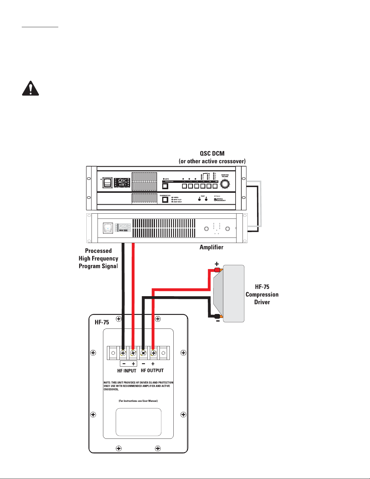
Connections
The HF-75 has barrier strip screw terminals that accept up to #10 AWG stranded loudspeaker wire.
HF INPUT Terminals
Connect the amplifier’s output signal to the loudspeaker’s HF INPUT terminals. Observe proper polarity; amplifier + signal to loudspeaker + HF INPUT, amplifier - signal to loudspeaker - HF INPUT. Use the largest wire size and shortest length for the application.
NOTE! Maintain proper loudspeaker connection polarity throughout the entire system for maximum performance.
Do not apply full range signal to the HF-75! There is no crossover in the HF-75, only a compensation/delay network. All required signal processing must be done upstream of the HF-75.
HF OUTPUT Terminals
The HF OUTPUT terminals are factory-connected to the compression driver. These terminals should ONLY be connected to the HF-75’s
compression driver.
Page 3

HF-75 Specifications (subject to change without notice)
Frequency Range: 600 - 16k Hz (-6 dB, full space)
Nominal Coverage: 90° horizontal X +20 to -30° vertical (50° total, adjustable mount provides for vertical plane adjustments. The hori-
zontal plane can be adjusted by altering mounting position on the LF-4215 enclosure before tightening bolts.
DI: 9.0 dB (600 to 16,000 Hertz average)
Q: 8.0 (600 to 16,000 Hertz average)
Maximum Output: 133 dB SPL calculated peak, 1 meter, half space.
Impedance: 8 ohms nominal
8.0 ohms minimum at 3,000 Hertz
104 ohms maximum at 475 Hertz
Maximum Input Power: 60 watts rms (100 hours of 6 dB crest factor pink noise, 500 to 20,000 Hertz, IEC method)
80 watts rms (2 hours of 6 dB crest factor pink noise, 60 - 6,000 Hertz, AES method)
Sensitivity: 108 dB half space, 1 watt, 1 meter
Crossover Frequency: 700 Hertz or higher, 24 dB per octave
Connectors: Barrier strip screw terminals accept up to #10 AWG stranded wire. Four terminals: (two HF INPUT and two post
compensation HF OUTPUT). HF OUTPUT factory wired to compression driver.
Transducers: 1.5” (38mm) exit, 3.0” (76mm) titanium diaphragm compression driver.
Mounting Hardware: Attaches to top of LF-4215 cabinet using three 5/16”-18 x 3/4” long bolts.
Size: 15” wide X 20” high X 12” deep (285mm X 508mm X 364mm)
Weight: 50 lbs. (shipping), 40 lbs. (net), 22.7/18.4 kilograms
Page 4

Warranty (USA only; other countries, see your dealer or distributor)
Disclaimer
QSC Audio Products, Inc. is not liable for any damage to amplifiers, or any other equipment that is caused by negligence or
improper installation and/or use of this loudspeaker product.
QSC Audio Products 3 Year Limited Warranty
QSC Audio Products, Inc. (“QSC”) guarantees its products to be free from defective material and / or workmanship for a period
of three (3) years from date of sale, and will replace defective parts and repair malfunctioning products under this warranty
when the defect occurs under normal installation and use - provided the unit is returned to our factory or one of our authorized
service stations via pre-paid transportation with a copy of proof of purchase (i.e., sales receipt). This warranty provides that
the examination of the return product must indicate, in our judgment, a manufacturing defect. This warranty does not extend
to any product which has been subjected to misuse, neglect, accident, improper installation, or where the date code has been
removed or defaced. QSC shall not be liable for incidental and/or consequential damages. This warranty gives you specific
legal rights. This limited warranty is freely transferable during the term of the warranty period.
Customer may have additional rights, which vary from state to state.
In the event that this product was manufactured for export and sale outside of the United States or its territories, then this limited warranty shall not apply. Removal of the serial number on this product, or purchase of this product from an unauthorized
dealer, will void this limited warranty. Periodically, this warranty is updated. To obtain the most recent version of QSC’s warranty statement, please visit www.qscaudio.com. Contact us at 800-854-4079 or visit our website at www.qscaudio.com.
Contacting QSC Audio Products
Mailing address:QSC Audio Products, Inc.
1675 MacArthur Boulevard
Costa Mesa, CA 92626-1468 USA
Telephone Numbers:
Main Number (714) 754-6175
Sales & Marketing (714) 957-7100 or toll free (USA only) (800) 854-4079
Customer Service(714) 957-7150 or toll free (USA only) (800) 772-2834
Facsimile Numbers:
Sales & Marketing Fax(714) 754-6174
Customer Service Fax(714) 754-6173
World Wide Web:www.qscaudio.com
E-mail:info@qscaudio.com
service@qscaudio.com
QSC Audio Products, Inc. 1675 MacArthur Boulevard Costa Mesa, California 92626 USA
©2003 “QSC” and the QSC logo are registered with the U.S. Patent and Trademark Office.
 Loading...