

Page 1
TM
GX POWER AMPLIFIER SERIES
User Manual
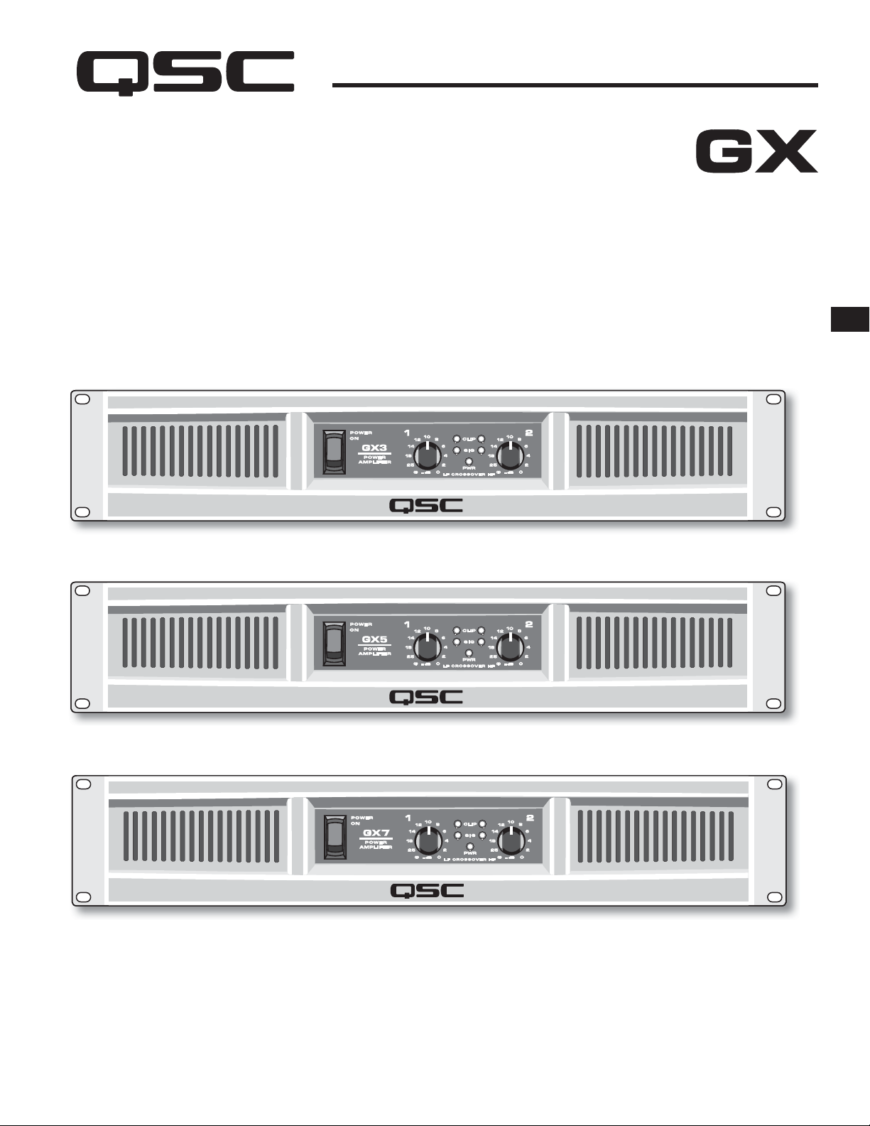
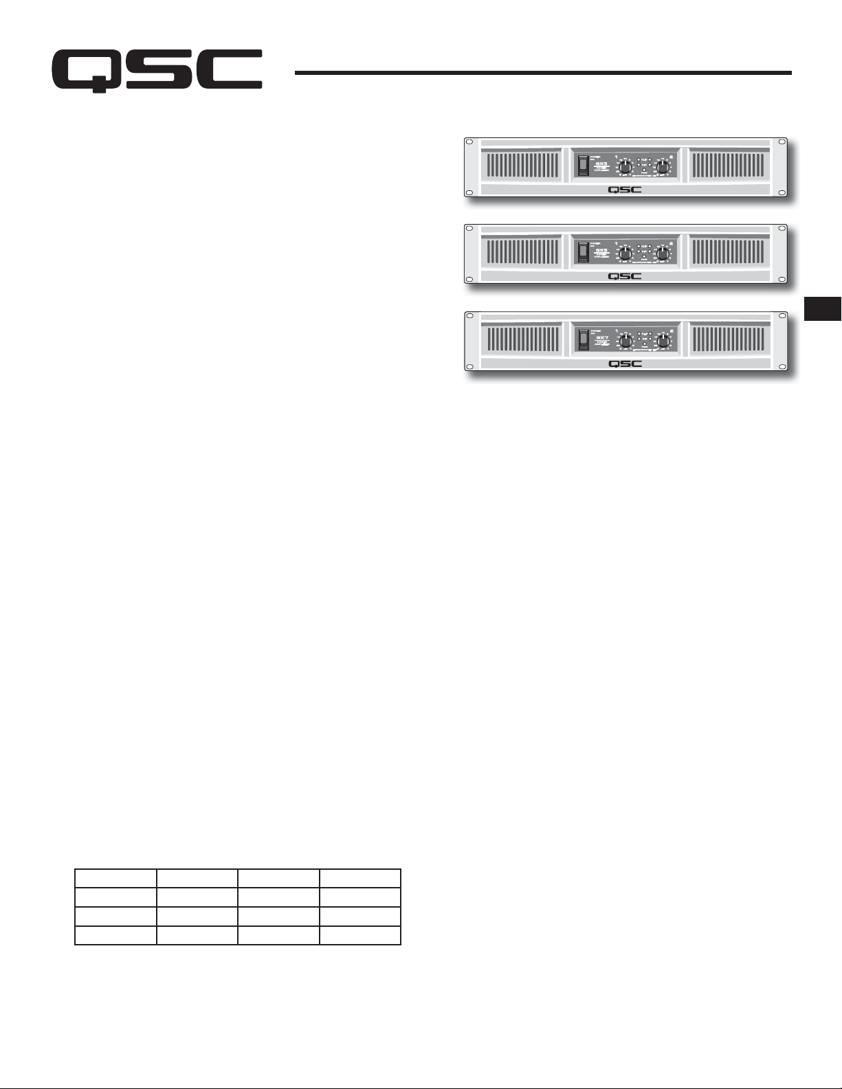
GX3 300 watts per channel at 8 ohms
GX5 500 watts per channel at 8 ohms
GX7 725 watts per channel at 8 ohms
EN
TD-000271-00-F
*TD-000271-00*
Page 2

IMPORTANT SAFETY PRECAUTIONS AND EXPLANATION OF SYMBOLS
1- Read these instructions.
2- Keep these instructions.
3- Heed all warnings.
4- Follow all instructions.
5- WARNING: To prevent fi re or electric shock, do not expose this equipment to rain or moisture. Do not use this apparatus near water.
6- Clean only with a dry cloth.
7- Do not block any ventilation openings. Install in accordance with the manufacturer’s instructions.
8- Do not install near any heat sources such as radiators, heat registers, stoves, or other apparatus (including amplifi ers) that produce heat.
9- The appliance coupler is the AC mains disconnect and should remain readily operable after installation.
10- Do not defeat the safety purpose of the grounding-type plug. A grounding plug has two blades and a grounding prong. The wide blade or third
EN
prong are provided for your safety. If the provided plug does not fi t your outlet, consult an electrician for the replacement of the obsolete outlet.
This apparatus should be connected to a receptacle with a protective earthing (or ground) connection.
11- Protect the power cord from being walked on or pinched, particularly at plugs, convenience receptacles, and the point where they exit from the
apparatus.
12- Use only attachments/accessories specifi ed by QSC Audio Products, LLC
13- Use only with hardware, brackets, stands, and components sold with the apparatus or by QSC Audio Products, LLC
14- Unplug the apparatus during lightning storms or when unused for long periods of time.
15- Refer all servicing to qualifi ed service personnel. Servicing is required when the apparatus has been damaged in any way, such as power supply
cord or plug is damaged, liquid has been spilled or objects have fallen into the apparatus, the apparatus has been exposed to rain or moisture,
does not operate normally, or has been dropped.
2
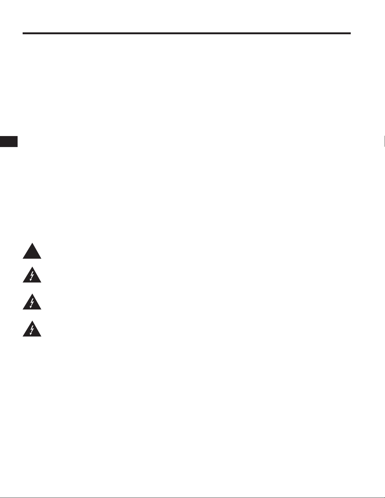
The exclamation point within an equilateral triangle is intended to alert the user to the presence of important operating and maintenance
!
FCC INTERFERENCE STATEMENT
NOTE: This equipment has been tested and found to comply with the limits for a class B digital device, pursuant to part 15 of the FCC rules. These
limits are designed to provide reasonable protection against harmful interference in a residential installation. This equipment generates, uses, and can
radiate radio frequency energy and if not installed and used in accordance to the instructions, may cause harmful interference to radio communications.
However, there is no guarantee that interference will not occur in a particular installation. If this equipment does cause harmful interference to radio or
television reception, which can be determined by switching the equipment off and on, the user is encouraged to try to correct the interference by one or
more of the following measures:
Reorient or relocate the receiving antenna.
Increase the separation between the equipment and the receiver.
Connect the equipment into an outlet on a circuit different from that to which the receiver is connected.
Consult the dealer or an experienced radio or TV technician for help.
(servicing) instructions in this manual.
The lightning fl ash with arrowhead symbol within an equilateral triangle is intended to alert the user to the presence of uninsulated
“dangerous” voltage within the product’s enclosure that may be of suffi cient magnitude to constitute a risk of electric shock
to humans.
CAUTION: TO REDUCE THE RISK OF ELECTRIC SHOCK, DO NOT REMOVE THE COVER. NO USER-SERVICEABLE PARTS INSIDE. REFER
SERVICING TO QUALIFIED PERSONNEL.
WARNING: To prevent fi re or electric shock, do not expose this equipment to rain or moisture.
© Copyright 2010, QSC Audio Products, LLC
QSC® is a registered trademark of QSC Audio Products, LLC
“QSC” and the QSC logo are registered with the U.S. Patent and Trademark Offi ce
All trademarks are the property of Speakon® and PowerCon® are registered trademarks of Neutrik LLC their respective owners.
Page 3

WELCOME
Thank you for purchasing a QSC Audio amplifi er. The GX Series is
the latest in a long line of hard-working, low cost amplifi ers, designed
to produce the best possible results for a wide range of users. In
most cases, you can plug and play with no surprises, but for best
results, we recommend you review the enclosed user guide.
3
GX POWER AMPLIFIER SERIES
Professional Power Amplifi ers
UNPACKING
Confi rm that the amplifi er has no visible shipping damage. Confi rm
that amplifi er has the correct AC cord and voltage rating for your
region (See rear panel, Serial Number plate). It is best to keep the
carton in case the amplifi er needs to be returned, at least until it has
been tested.
SUPPORT AND SERVICE
QSC Audio Products maintains a world-wide network of distributors
and service centers. These local agencies will be able to answer your
questions and take care of any problems.
QSC WEBSITE
Our website, www.qscaudio.com, is factory-maintained and
supported in multiple languages. Visit frequently for new
announcements, typical questions, and other user information.
IMPORTANT SAFETY PRECAUTIONS
QSC products are designed for safe operation, and have been
certifi ed by recognized product safety agencies to meet all normal
standards for this type of product. However, dangerous voltages
and power levels exist within the covers of this amplifi er. The user
is requested to study the precautions in this manual. If the product
has been dropped, dented, soaked, or appears to have loose parts
inside, the risk of shock is increased. Unplug the AC cord, and take
the product to qualifi ed service personnel for inspection and repairs.
POWER RATINGS
Watts at 0.1% clipping, both channels driven
EN
FEATURES
Power levels matched to the most popular speakers used by
entertainers.
Optimized for maximum real-world headroom into 4Ω and 8Ω
speaker systems.
Inputs: XLR, 1/4” TRS and phono input connectors for
compatibility with any source.
Outputs: Speakon® combo accepts 1/4” (TS) plugs or Speakon
2-pole and 4-pole plugs (connects 2 poles only). Binding posts
support all other speaker wiring systems.
Minimum depth chassis (only 10.1” / 257 mm) fi ts in compact,
inexpensive effects racks.
Light weight – less than 26 lbs (12.5 kg).
Detented gain controls for precise setting and matching of
sensitivity.
GuardRail automatically protects the amplifi er and loudspeakers
from damage due to temperature rise or overdrive without
shutting down the show.
Front panel LEDs monitor Power, Signal and Clipping.
Model
GX3 300 425 200
GX5 500 700 350
GX7 725 1000 600
*NOTE: 2-ohm loading is not recommended for high power use.
To avoid protective limiting, use only at low levels.
8 ohms 4 ohms 2 ohms*
Subwoofer / Satellite crossover built-in.
Page 4
FRONT PANEL FEATURES
EN
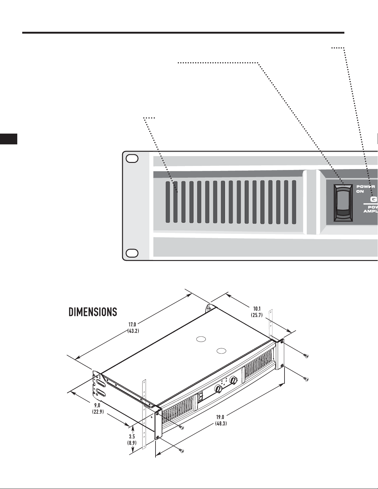
ON-OFF SWITCH
Move the rocker switch up to turn on the amplifi er.
The blue PWR LED will turn on immediately.
The red CLIP LEDs may trigger for 1-2 seconds until the amp
has completed its turn-on cycle. If no lights come on, check the
power cord and the AC reset on the rear panel.
COOLING VENTS
The internal fan moves air through the chassis to
reduce temperature rise. Keep vents clear. The fan
speeds up in response to heavy use.
4
MODEL NUMBER
The GX3, GX5, and GX7
power ratings are shown on
the Specifi cations page.
inches (cm)
Page 5

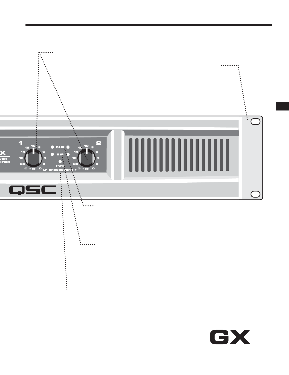
GAIN CONTROLS, CH1, CH2
The markings show attenuation in dB. For normal
use, keep the control in the upper half of its range
(less than 10 dB of attenuation). If set below half,
the source may overload before the amplifi er
reaches full power.
5
RACK MOUNTING
Fits standard 19-inch rack, 2RU.
Accepts #10 or 6 mm screws,
as determined by the rack rails.
Add rear support to prevent
damage in portable rigs.
EN
RED CLIP LEDS
Red fl ashing indicates the amp is being overdriven. Heavy overdrive triggers internal gain
reduction, to reduce overload distortion. Normal gain will resume after the signal level returns to
normal. See Troubleshooting if the red LED remains on continuously.
GREEN SIGNAL LEDS
The green LED starts fl ashing on soft signals (-35 dB), and changes to steady green as the
signal level increases.
BLUE POWER LED
The blue PWR (POWER) LED indicates that the AC switch is on, and the amp is receiving
power. Within two seconds, it is ready to use.
ALTERNATE GAIN MARKING
When the CROSSOVER switch is active (see rear panel),
LF (CH 1) controls low frequencies (subwoofer),
HF (CH 2) controls the high frequencies (mid-high box).
Page 6
REAR PANEL FEATURES
6
EN
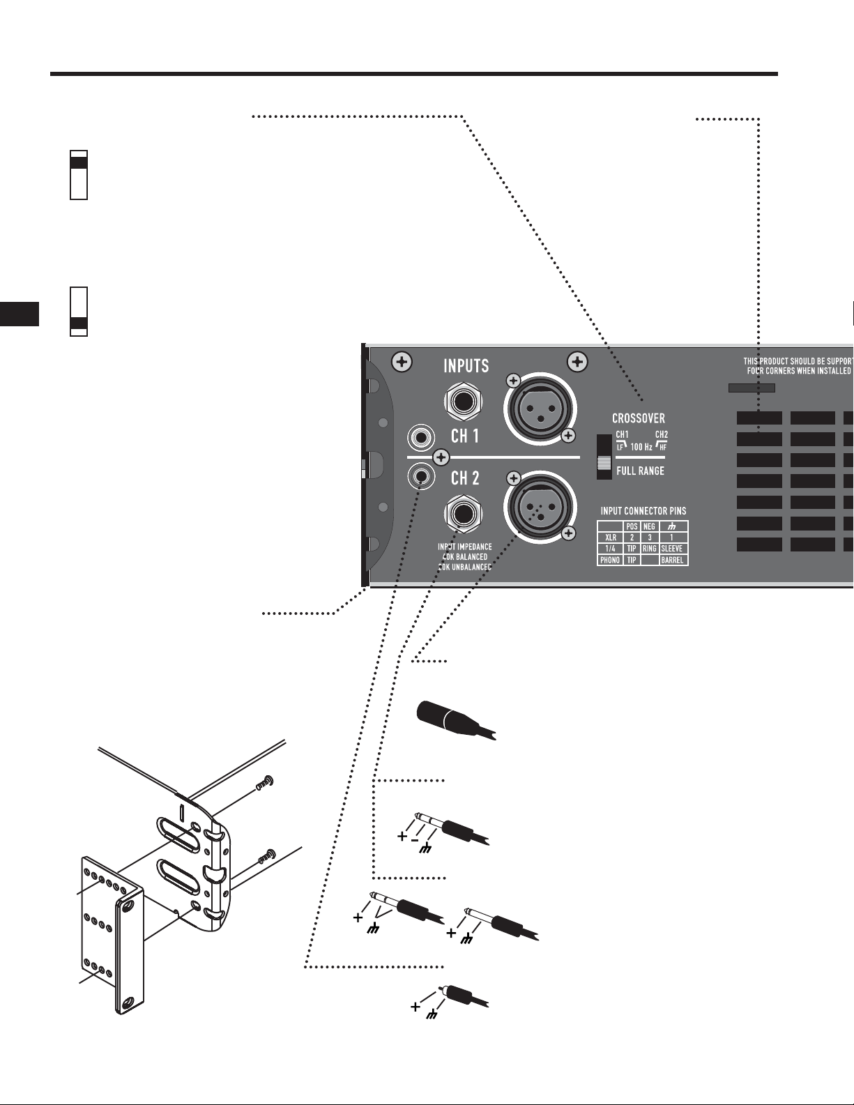
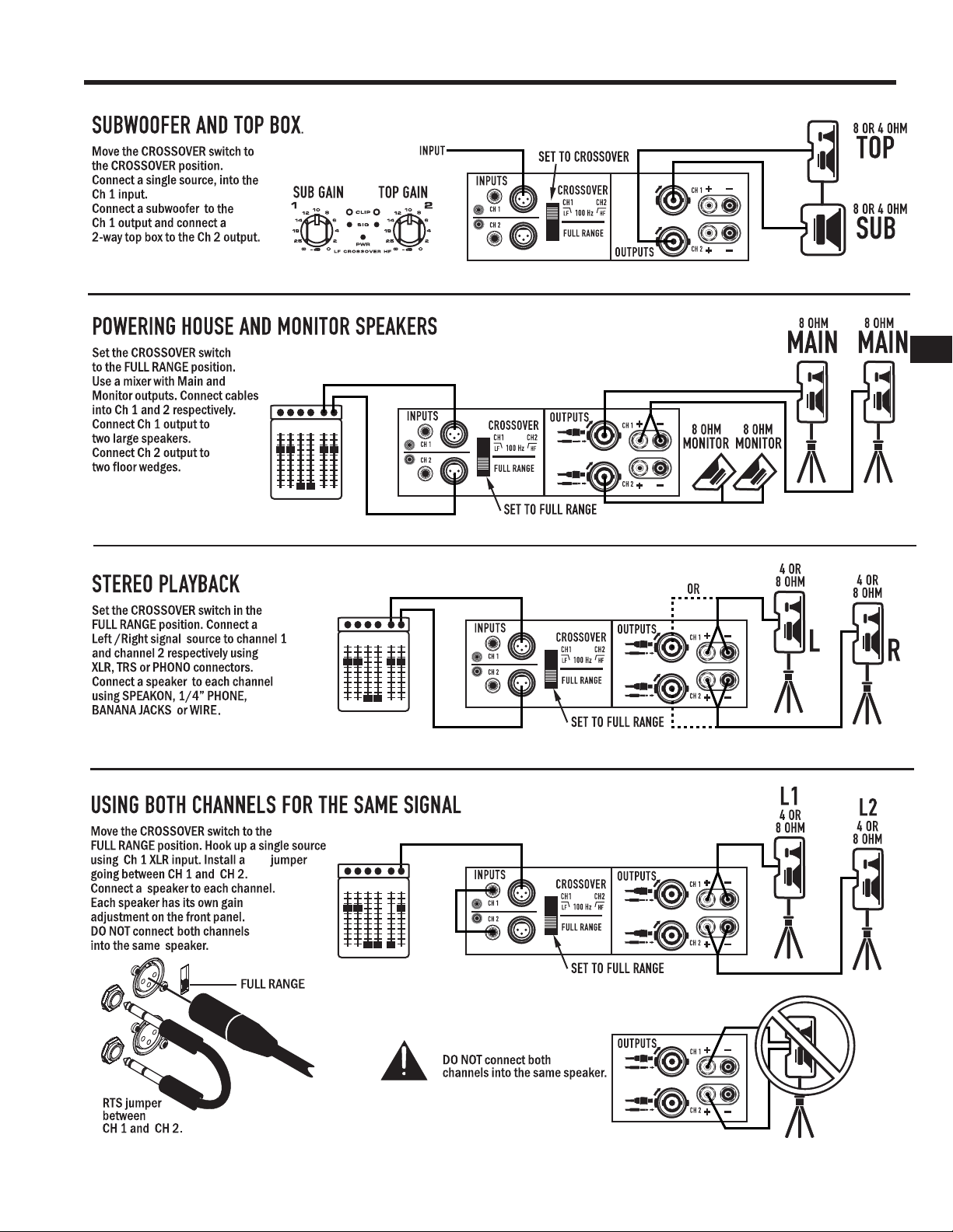
CROSSOVER SWITCH
CROSSOVER POSITION
Splits a full-range signal to drive a subwoofer and top box.
CH 1 receives the lows, from 20-100Hz, for the subwoofer.
CH 2 receives 100Hz to 20kHz, to power a full range speaker.
When using CROSSOVER mode, connect signal to CH 1 only.
Use the two Gain controls to balance the LF and HF signals
(see Front Panel).
FULL RANGE POSITION
For normal, 2-channel use with all inputs active.
The crossover is bypassed.
EXHAUST VENT
Keep vent clear. Install in
open-back rack.
REAR EAR MOUNTING
Rear ears designed for protecting the
rear connector wire dressing and
supporting the amplifi er in a rack. A rear
rack support mounting kit (model FG000031-00 pack of two) is available from
QSC Technical Services Group.
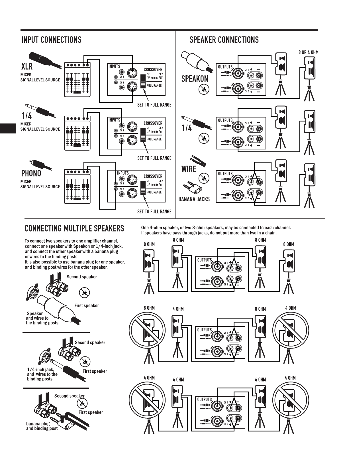
INPUT CONNECTIONS
BALANCED XLR INPUTS
Pin 2 Positive, Pin 3 Negative, Pin 1 Shield (Ground).
Recommended for long or short runs, either fi xed or
frequently changed. Each channel’s XLR and TRS jacks
are connected internally, and provide feed thru
to the other connector.
BALANCED 1/4-INCH TRS INPUTS
Tip positive, Ring Negative, Sleeve Shield (Ground).
Recommended for long or short runs that are frequently
changed.
UNBALANCED 1/4-INCH TS INPUTS
Accepts unbalanced 1/4-inch plugs for short runs.
Tip positive, Sleeve Shield (Ground).
UNBALANCED PHONO INPUTS
Tip Positive, Barrel Shield (Ground). Recommended
for semi-permanent connections to nearby sources,
within the same rack. NOTE: when using these
inputs, the TRS or XLR inputs should not be used.
Page 7
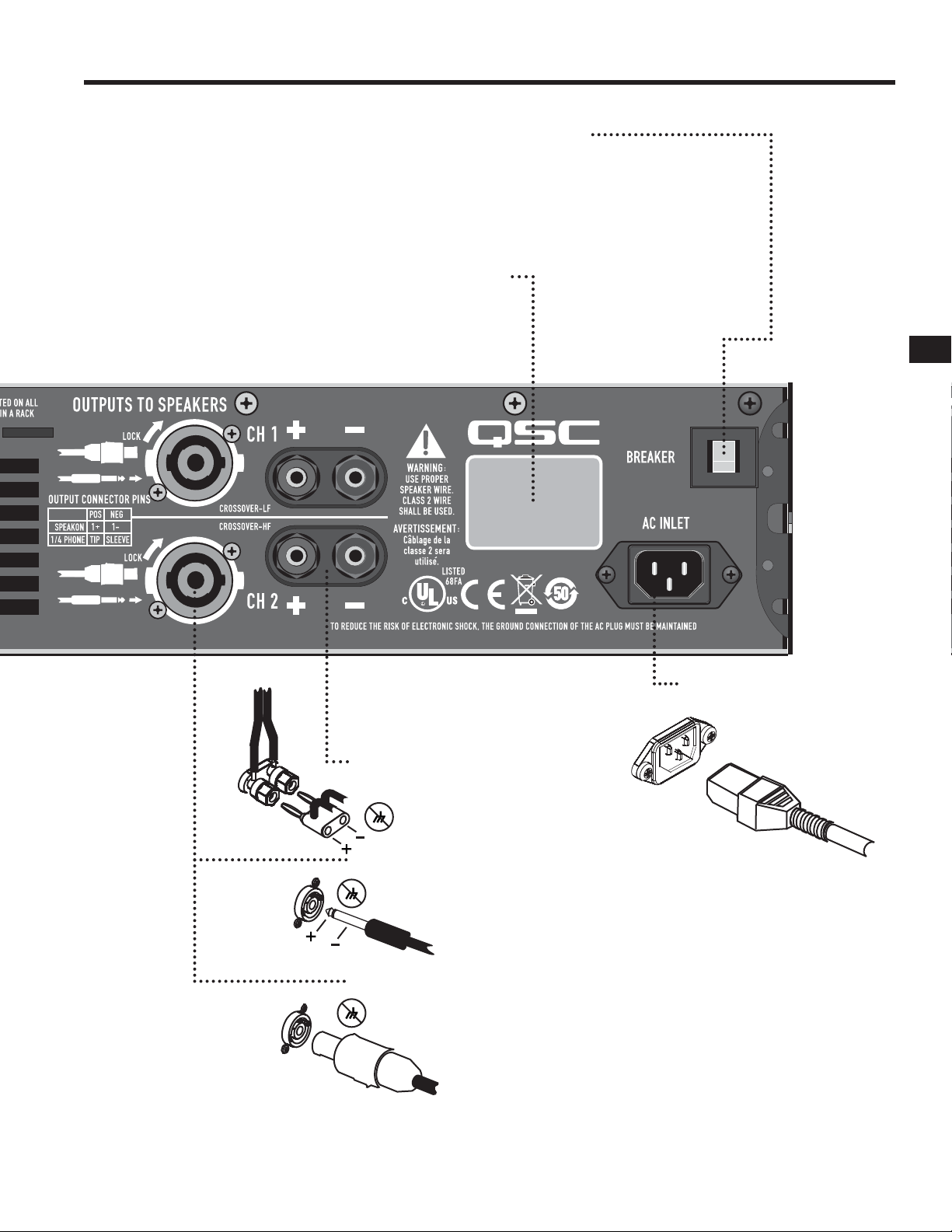
AC BREAKER RESET
If the amplifi er shuts off after a long burst of power,
turn off the AC switch and check the circuit breaker.
The button can be pressed back in after a 30 second
cool-down period. If the breaker trips repeatedly,
the amplifi er may need servicing.
SERIAL NUMBER AND RATINGS
The rated AC voltage and output power
is shown on the serial number plate.
Record the serial number in a safe place.
7
EN
SPEAKER CONNECTIONS
BINDING POSTS
Accepts banana plugs
(not permitted in CE regions).
Bare wires or terminals may be
inserted into the side holes.
1/4-INCH CONNECTORS
Insert plug into the center of
the Speakon-Combo jack.
Use only heavy duty speaker cables.
SPEAKON CABLES (2 wire type):
Insert and turn until the connector clicks.
Use the thumb latch or locking ring
to release the plug.
AC INLET
Page 8
SYSTEM HOOKUP EXAMPLES
EN
8
Page 9
SYSTEM HOOKUP EXAMPLES
9
EN
TRS
Page 10

TROUBLESHOOTING
TROUBLESHOOTING
10
NO POWER, NO LIGHTS, NO FAN
Confi rm that the AC cord is fully seated and connected to a
live outlet. Check the AC source by trying another device
such as a lamp. Check the BREAKER on the back of the
amplifi er by pushing in the button. If the breaker trips off
quickly, the amplifi er needs servicing.
AMPLIFIER LOSES VOLUME
If the amplifi er is worked too hard, GuardRail™ will
reduce volume to prevent thermal muting. The fan should be
running at full speed. Reduce input signal somewhat and the
amp should return to normal gain within 1-2 minutes. If the
amp feels hot and the fan is not running, it needs to be
serviced.
EN
CHANNEL 1 PRODUCES DEEP BASS ONLY.
Check the position of the CROSSOVER switch on the rear
panel. Set on FULL RANGE for normal, independent use of
each channel.
CHANNEL 2 INPUT SEEMS DEAD.
Check the position of the CROSSOVER switch on the rear
panel. Set on FULL RANGE for normal, independent use of
each channel.
AMPLIFIER SOUNDS DISTORTED.
If the red CLIP LED is fl ashing, the amplifi er is being played
beyond its normal rated power. GuardRail™ circuitry will reduce
volume somewhat to prevent severe overdrive, but if the input
signal is further increased, the limiter can be overridden, with
increased distortion.
If the speakers or speaker cables are shorted or defective,
the amplifi er may distort at lower-than-normal levels, with
increased fl ashing of the red CLIP LED. This should be
checked by trying an alternate speaker and cable.
NO SOUND, WITH BLUE LED ONLY, NO GREEN OR
RED LED
Confi rm that the Gain controls are turned up. Confi rm that
the input cables are correctly installed at both ends. If using
1/4-inch speaker cables, do not confuse with input cables.
Confi rm that the source is active. If necessary, try another
source, or connect another amplifi er to the existing source.
NO SOUND, BUT THE GREEN LED IS RESPONDING
The green LED indicates the amp is producing a signal, so
sound should be heard if the speaker is connected. Check
the speaker connections at both ends, and try a different
speaker.
NO SOUND, RED LED ON
The amp mutes briefl y when turned on and off to prevent
thumps. If the amp overheats severely, it will mute until it cools off.
The fan will be running at full speed, and sound should
resume in less than a minute. If the amp feels hot and the fan
is not running, it needs to be serviced.
BACKGROUND HUM
Balanced XLR or TRS cables are better for long runs. Hum can be a
problem when connecting to TV-cable rigs, since the TV cable often
creates a ground confl ict. Request or install a TV-cable isolator to
reduce this problem.
Hum can also occur earlier in the signal chain, depending on the
types of connections. It often helps to plug everything into the same
AC strip, if the total power consumption is not excessive.
As a last resort, mild hum can sometimes be reduced by
lowering the amp gain, and increasing the source gain to
compensate, but you must ensure that the source can deliver
the extra volume without overload distortion. If this does not
reduce hum, it is coming from the source.
If too many speakers are connected to each channel
(impedance below 4 ohms), the amp will overload more
easily and will probably run hot.
If the sound is distorted or garbled without fl ashing the red
CLIP LED, the distortion is not occurring inside the amplifi er.
Either the speaker is bad or the input signal is distorted.
• Confi rm that the speaker is OK by trying a different unit.
• Input overload can occur if the amplifi er Gain controls are set too
low, and the input source is overdriven to compensate Reduce the
source volume until the distortion clears up, and increase amp Gain
to reach the desired level. It is generally desireable to keep the
amp gains at or near their full, clockwise, position.
• Check all input connections. Do not plug two different sources into
the same channel. Use a mixer to blend sources.
AMPLIFIER NEEDS SERVICING
The following conditions indicate possible unsafe conditions
that require service before using. If observed, unplug the AC
cord from the wall and when safe, remove the amp for
servicing.
• If the amplifi er emits smoke or burning smells
• If the case is severely dented or deformed
• If the amplifi er is soaked with any fl uid
• If internal parts sound loose
• If the AC breaker trips when power is applied
• If the amplifi er is dropped, carefully inspect for damage or
loose parts before attempting to use.
Page 11
SPECIFICATIONS
SPECIFICATIONS
GX3 GX5 GX7
SPECIFICATION SUBJECT TO CHANGE WITHOUT NOTICE.
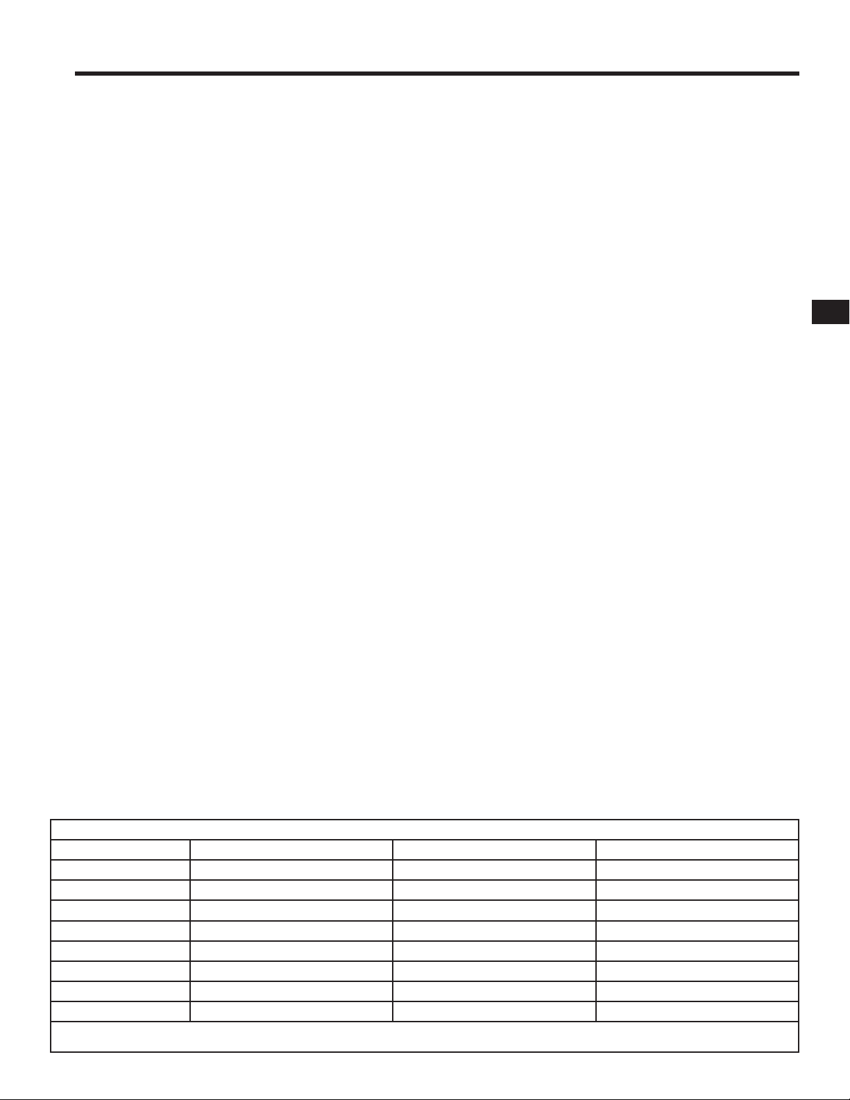
OUTPUT POWER, 1 kHz, 0.1 % clipping
8Ω, both channels driven 300 W 500 W 725W
8Ω, single channel driven 350 W 600 W 800W
4Ω, both channels driven 425 W 700 W 1000W
4Ω, single channel driven 500 W 850 W 1200W
2Ω, both channels driven, 1% clipping 200 W 350 W 600W
SIGNAL TO NOISE (20 Hz – 20 kHz) 100 dB
11
INPUT SENSITIVITY 1.2 Vrms
VOLTAGE GAIN AT 8Ω 32.2 dB 34.4 dB 36.1 dB
OUTPUT CIRCUITRY Class B 2-tier Class H 2-tier Class H
POWER REQUIREMENTS (1/8 power, pink noise 6.3 A 6 A 10.1 A
at 4Ω 120 V AC)
DISTORTION (1 dB below rated power, 1 kHz) 8Ω, less than 0.02%
4Ω, less than 0.05%
FREQUENCY RESPONSE 20 – 20kHz, +0, -1dB
DYNAMIC HEADROOM, 4Ω 2dB
INPUT IMPEDANCE Greater than 20K ohms (balanced or unbalanced)
MAXIMUM INPUT LEVEL +24 dB (16 Vrms)
INPUT CONNECTORS, each channel 3-pin XLR and 1/4” TRS, balanced, parallel
Phono, unbalanced
OUTPUT CONNECTORS, each channel Speakon®, 1/4”, Binding Posts
AMPLIFIER AND LOAD PROTECTION Short circuit, open circuit, thermal, RF protection
Load protected against DC faults
CONTROLS AND INDICATORS, FRONT PANEL Gain controls, 21 detents
Red Clip LEDs, proportional, 0.1% THD threshold.
Green Signal LEDs, threshold -35 dB
Blue Power LED, AC-on.
CONTROLS, REAR PANEL Full Range / Crossover switch
100 Hz, 3rd order LP (sub), 2nd order HP (top).
EN
DIMENSIONS (HWD) 3.5” (2RU) x 19” x 10.1” (89 mm x 483 mm x 257 mm)
WEIGHT – Shipping / Net 31 / 27 lbs (14.1 / 12.1 kg) 32 / 28 lbs (14.6 / 12.6 kg) 22 / 17 lbs (10 / 7.7 kg)
AGENCY APPROVALS UL, CE, RoHS / WEEE compliant. Meets FCC Class B EMI limits.
AC POWER CONSUMPTION 1/8 power, ohms (AC Current and Heating, 120Vac)
GX3 GX5 GX7
Operating Condition AC amps BTU / hr AC amps BTU / hr AC amps BTU / hr
Idle 0.2 44 0.3 60
8 + 8 ohms, 1/8 power (1) 4.1 904 3.3 734 7.6 1183
8 + 8 ohms, 1/3 power (2) 6.1 1160 8.5 1456 13.4 1807
8 + 8 ohms, full power (3) 9.75 1109 16.2 1891 26.5 2167
4 + 4 ohms, 1/8 power (1) 6.3 1515 5.8 1160 11.5 1908
4 + 4 ohms, 1/3 power (2) 9.4 2105 11.2 2162 18.5 2612
4 + 4 ohms, full power (3) 15.0 2297 24.5 3754 39.4 4478
(1) 1/8 power represents typical operating conditions.
(3) Full power is breaker limited to short periods.
(2) 1/3 power represents peak program levels.
(4) For 230V, multiply AC current by 0.5. For 100V, multiply AC current by 1.25.
0.6 82
Page 12

WARRANTY
(USA only; other countries, see your dealer or distributor)
Disclaimer
QSC Audio Products, LLC is not liable for any damage to amplifi ers or any other equipment that is caused by negligence or
improper installation and/or use of this loudspeaker product.
QSC Audio Products 3 Year Limited Warranty
QSC Audio Products, LLC ( QSC ) guarantees its products to be free from defective material and / or workmanship for a period
of three (3) years from date of sale, and will replace defective parts and repair malfunctioning products under this warranty when
the defect occurs under normal installation and use - provided the unit is returned to our factory or one of our authorized service
stations via prepaid transportation with a copy of proof of purchase (i.e., sales receipt). This warranty provides that the examination
of the return product must indicate, in our judgment, a manufacturing defect. This warranty does not extend to any product which
has been subjected to misuse, neglect, accident, improper installation, or where the date code has been removed or defaced.
EN
QSC shall not be liable for incidental and/or consequential damages. This warranty gives you specifi c legal rights. This limited
warranty is freely transferable during the term of the warranty period. Customer may have additional rights, which vary from state
to state.
In the event that this product was manufactured for export and sale outside of the United States or its territories, then this
limited warranty shall not apply. Removal of the serial number on this product, or purchase of this product from an unauthorized
dealer, will void this limited warranty. Periodically, this warranty is updated. To obtain the most recent version of QSC’s warranty
statement, please visit www.qscaudio.com. Contact us at 800-854-4079 or visit our website at www.qscaudio.com.
How to Contact QSC Audio Products
Mailing address:
QSC Audio Products, LLC
1675 MacArthur Boulevard
Costa Mesa, CA 92626-1468 USA
Telephone Numbers:
Main Number (714) 754-6175
Sales & Marketing (714) 957-7100 or toll free (USA only) (800) 854-4079
Customer Service (714) 957-7150 or toll free (USA only) (800) 772-2834
Facsimile Numbers:
Sales & Marketing FAX (714) 754-6174
Customer Service FAX (714) 754-6173
World Wide Web:
www.qscaudio.com
E-mail: info@qscaudio.com
service@qscaudio.com
TM
QSC Audio Products, LLC 1675 MacArthur Boulevard Costa Mesa, California 92626 USA
©2007 “QSC” and the QSC logo are registered with the U.S. Patent and Trademark Offi ce.
Page 13

TM
SERIE DE AMPLIFICADORES DE POTENCIA GX
Manual del usuario
GX3 300 vatios por canal a 8 ohmios
GX5 500 vatios por canal a 8 ohmios
GX7 725 vatios por canal a 8 ohmios
SP
TD-000271-00-F
*TD-000271-00*
Page 14
IMPORTANTES PRECAUCIONES DE SEGURIDAD Y EXPLICACIÓN DE LOS SÍMBOLOS
1- Lea estas instrucciones.
2- Conserve estas instrucciones.
3- Observe todas las advertencias.
4- Siga todas las instrucciones.
5- ADVERTENCIA: Para prevenir incendios o descargas eléctricas, no exponga este equipo a la lluvia ni a la humedad.
No use este aparato cerca del agua.
6- Límpielo sólo con un paño seco.
7- No obstruya ninguna abertura de ventilación. Instale de acuerdo con las instrucciones del fabricante.
8- No lo instale cerca de fuentes de calor tales como radiadores, registros térmicos, estufas ni otros aparatos (inclusive amplifi cadores) que
produzcan calor.
9- El acoplador del equipo es la desconexión de la línea principal de CA y debe permanecer fácilmente operable después de la instalación.
SP
10- No anule la característica de seguridad del enchufe con conexión a tierra. Un enchufe con conexión a tierra tiene dos hojas y una patilla de
conexión a tierra. La hoja ancha o el tercer terminal se proporcionan para su seguridad. Si el enchufe que se le proporciona no cabe en su
tomacorriente, consulte con un electricista para reemplazar el tomacorriente obsoleto. Este aparato debe estar conectado a un receptáculo con
una conexión de protección a masa (o tierra).
11- Proteja el cable de alimentación para que no se camine sobre él ni se le comprima, particularmente en los enchufes, los receptáculos y el punto
en donde éstos salen del aparato.
12- Use sólo piezas/accesorios especifi cados por QSC Audio Products, LLC
13- Use sólo con herraje, soportes, estantes y componentes vendidos con el aparato o por QSC Audio Products, LLC
14- Desenchufe el aparato durante tormentas eléctricas o cuando no lo vaya a usar durante periodos prolongados de tiempo.
15- Refi era todo el servicio a personal califi cado. Es necesario dar servicio al aparato cuando sufra algún daño, como cuando se daña el cable de
alimentación eléctrica o el enchufe, cuando se derraman líquidos o caen objetos sobre el aparato, cuando éste ha estado expuesto a la lluvia o
humedad, cuando no opere normalmente o cuando se haya caído.
14
!
DECLARACIÓN DE LA FCC RESPECTO A LA INTERFERENCIA
NOTA: Este equipo ha sido probado y se ha determinado que cumple con los límites de un dispositivo digital Clase B, en virtud de la parte 15 de las
reglas de la FCC. Estos límites están diseñados para proporcionar protección razonable contra interferencia dañina en una instalación residencial. Este
equipo genera, usa y puede irradiar energía de radiofrecuencia, y si no se instala y usa de acuerdo con las instrucciones, puede causar interferencia
dañina a las comunicaciones de radio. Sin embargo, no hay garantía que no ocurrirá interferencia en una instalación en particular. Si este equipo causa
interferencia dañina a la recepción de radio o televisión, lo cual se puede determinar al apagar y encender el equipo, se recomienda al usuario que trate
de corregir la interferencia en una o más de las siguientes maneras:
Reoriente o reubique la antena receptora.
Aumente la separación entre el equipo y el receptor.
Conecte el equipo en un tomacorriente de un circuito diferente al cual está conectado el receptor.
Consulte al distribuidor o a un técnico experimentado de radio o TV para solicitar ayuda.
El signo de exclamación dentro de un triángulo equilátero tiene la intención de alertar al usuario de la presencia de importantes instrucciones de
operación y mantenimiento (servicio) en este manual.
El símbolo del rayo con una punta de fl echa dentro de un triángulo equilátero tiene la intención de alertar al usuario de la presencia de voltaje
“peligroso” no aislado dentro de la caja del producto, que puede ser de magnitud sufi ciente para constituir un riesgo de descarga eléctrica
para los seres humanos.
PRECAUCIÓN: PARA REDUCIR EL RIESGO DE DESCARGA ELÉCTRICA, NO QUITE LA CUBIERTA. EL INTERIOR NO CONTIENE PIEZAS A
LAS
QUE EL USUARIO PUEDA DAR SERVICIO. REFIERA EL SERVICIO A PERSONAL CALIFICADO.
ADVERTENCIA: Para prevenir incendios o descargas eléctricas, no exponga este equipo a la lluvia ni a la humedad.
© Copyright 2010, QSC Audio Products, LLC
QSC® es una marca comercial registrada de QSC Audio Products, LLC
“QSC” y el logotipo de QSC están registrados con la Ofi cina de Patentes y Marcas Comerciales de los Estados Unidos
Speakon® y PowerCon® son marcas registradas de Neutrik LLC y sus respectivos propietarios. Todas las marcas comerciales
registradas son propiedad de sus respectivos dueños.
Page 15
SERIE DE AMPLIFICADORES DE POTENCIA GX
BIENVENIDO
Gracias por adquirir un amplifi cador de QSC Audio. La serie GX es
la última de una larga línea de amplifi cadores resistentes y de bajo
costo, diseñados para producir los mejores resultados a una gran
variedad de usuarios. En la mayoría de los casos, puede enchufar
y reproducir sin sorpresas, pero para obtener resultados óptimos,
recomendamos que revise la guía del usuario adjunta.
DESEMBALAJE
Confi rme que el amplifi cador no haya sufrido daños visibles durante
el envío. Confi rme que el amplifi cador tenga el cable de CA y la
clasifi cación de voltaje correctos para su región (consulte la placa
con el número de serie en el panel posterior). Es buena idea guardar
la caja en el caso de que sea necesario devolver el amplifi cador, al
menos hasta el momento de haberlo probado.
ASISTENCIA Y SERVICIO TÉCNICO
QSC Audio Products mantiene una red internacional de
distribuidores y centros de servicio. Estas agencias locales podrán
responder sus preguntas y solucionar cualquier problema.
15
Amplifi cadores profesionales de potencia
SP
CARACTERÍSTICAS
Niveles de potencia equiparados a los altavoces más populares
usados por los artistas.
Optimizado para un máximo espacio libre del mundo real en
sistemas de altavoces de 4Ω y 8Ω.
do
SITIO WEB DE QSC
Nuestro sitio web, www.qscaudio.com, se mantiene en la fábrica y
está disponible en varios idiomas. Visítelo frecuentemente para leer
los anuncios nuevos, ver las preguntas típicas y enterarse de otra
información para el usuario.
PRECAUCIONES IMPORTANTES DE
SEGURIDAD
Los productos de QSC están diseñados para su operación segura, y
agencias reconocidas de seguridad de los productos certifi can que
cumplen con todas normas habituales para este tipo de producto.
Sin embargo, dentro de este amplifi cador existen voltajes peligrosos
y niveles de potencia. Se solicita al usuario leer las precauciones en
este manual. Si el producto se ha caído, abollado, mojado o parece
tener piezas sueltas en su interior, se aumentará el riesgo de sufrir
descargas eléctricas. Desenchufe el cable de CA y lleve el producto
al personal de servicio califi cado para su inspección y reparaciones.
CLASIFICACIONES DE POTENCIA
Vatios a un recorte del 0.1%, ambos canales excitados
Modelo 8 ohmios 4 ohmios 2 ohmios*
GX3 300 425 200
GX5 500 700 350
GX7 725 1000 600
Entradas: Conectores XLR, TRS de 1/4” y de entrada de sonido
compatibles con cualquier fuente.
Salidas: La combinación Speakon® acepta enchufes de 1/4”
(TS) o enchufes Speakon de 2 polos y de 4 polos (sólo conecta
2 polos). Los bornes de conexión aceptan todos los demás
sistemas de cableado de altavoces.
El chasis de profundidad mínima (sólo 10.1” / 257 mm) cabe
en bastidores para equipo de efectos, que son compactos y
económicos.
Liviano – menos de 26 lbs (12.5 kg).
Controles de ganancia con retenes para ajustar y equiparar la
sensibilidad.
GuardRail automáticamente protege el amplifi cador y los
altavoces contra daños debido al aumento de la temperatura o a
la sobreexcitación sin interrumpir el espectáculo.
Los indicadores LED del panel frontal supervisan la potencia, la
señal y el recorte.
Cruce de subwoofer / satelital incorporado.
*NOTA: No se recomienda una carga de 2 ohmios para uso a alta potencia.
Para evitar la limitación de protección, utilícelo sólo a niveles bajos.
Page 16

CARACTERÍSTICAS DEL PANEL FRONTAL
CONMUTADOR DE ENCENDIDO-APAGADO
Mueva el conmutador basculante hacia arriba para encender el amplifi cador.
El indicador LED azul PWR se encenderá inmediatamente.
Los indicadores LED rojos CLIP pueden activarse durante 1-2 segundos hasta que el amplifi cador
haya completado su ciclo de encendido. Si no vuelven a encenderse las luces, verifi que el cable de
alimentación y el restablecimiento de CA en el panel posterior.
SP
16
NÚMERO DE MODELO
Las clasifi caciones de potencia
GX3 y GX5 se muestran en la
página de especifi caciones.
ABERTURAS DE VENTILACIÓN
El ventilador interno mueve el aire a través del chasis para
reducir el aumento de temperatura. Mantenga las aberturas
libres de obstrucciones. El ventilador se acelera como
respuesta al uso pesado.
Page 17
CONTROLES DE LA GANANCIA, CH1, CH2
Las marcas muestran la atenuación en dB. Para uso
normal, mantenga el control en la mitad superior de
su intervalo (menos de 10 dB de atenuación). Si se
ajusta por debajo de la mitad, la fuente de la señal
puede sobrecargarse antes de que el amplifi cador
llegue a la máxima potencia.
17
MONTAJE EN BASTIDOR
Cabe en un bastidor estándar de 19
pulgadas, 2RU.
Acepta tornillos número 10 o de 6 mm,
dependiendo de los rieles del bastidor.
Añada un soporte posterior para evitar
daños en el equipo portátil.
SP
INDICADORES LED ROJOS DE RECORTE
Si parpadean de color rojo, signifi ca que el amplifi cador está siendo sobreexcitado. Una
sobreexcitación signifi cativa activa una reducción interna de la ganancia, para reducir la
distorsión de la sobrecarga. Cuando el nivel de la señal regrese a su nivel normal, se reanudará
la ganancia normal . Consulte la sección sobre resolución de problemas si el indicador LED rojo
permanece encendido de manera continua.
INDICADORES LED VERDES DE SEÑAL
El indicador LED verde comienza a parpadear al haber señales tenues (-35 dB), y cambia
hasta ponerse verde permanente a medida que aumenta el nivel de la señal.
INDICADOR LED DE ENCENDIDO
El indicador LED azul PWR (encendido) indica que el conmutador de CA está encendido, y que
el amplifi cador está recibiendo alimentación. Al cabo de dos segundos, está listo para usar.
MARCA DE GANANCIA ALTERNATIVA
Cuando el conmutador CROSSOVER (cruce) está activo (consulte el panel posterior),
LF (CH 1) controla las bajas frecuencias (subwoofer),
HF (CH 2) controla las altas frecuencias (caja media-alta).
Page 18

CARACTERÍSTICAS DEL PANEL POSTERIOR
18
SP
CONMUTADOR DE CRUCE
POSICIÓN DE CRUCE
Divide una señal de intervalo completo para excitar un subwoofer y caja superior.
El canal CH 1 recibe los bajos, de 20 a 100Hz, para el subwoofer.
El canal CH 2 recibe 100Hz a 20kHz, para alimentar un altavoz de intervalo
completo.
Al usar el modo CROSSOVER, conecte la señal únicamente a CH 1.
Utilice los dos controles de ganancia para equilibrar las señales LF y HF
(consulte el panel frontal).
POSICIÓN DE INTERVALO COMPLETO
Para un uso normal con 2 canales, utilice con todas las entradas
activas. El cruce se elude.
ABERTURA DE
DESCARGA
Mantenga la abertura libre
de obstrucciones. Instale en
un bastidor de fondo abierto.
MONTAJE EN LAS OREJAS
POSTERIORES
Hay orejas posteriores diseñadas para proteger
el aislamiento de los hilos del conector posterior
y soportar el amplifi cador en un bastidor. Está
disponible un juego de montaje de apoyo en el
bastidor posterior (modelo FG-000031-00, paquete de
dos unidades) en el Grupo de Servicios Técnicos de
QSC.
CONEXIONES DE ENTRADA
ENTRADAS XLR EQUILIBRADAS
Patilla 2 Positivo, Patilla 3 Negativo, Patilla 1 Blindaje
(Tierra). Recomendadas para tramos largos o cortos,
fi jos o que se cambian frecuentemente. Los enchufes
XLR y TRS de cada canal se conectan internamente, y
proporcionan un pasaje al otro conector.
ENTRADAS EQUILIBRADA Y TRS DE 1/4 DE PULGADA
Punta Positivo, Anillo Negativo, Funda Blindaje (Tierra).
Recomendadas para tramos largos o cortos que se
cambian con frecuencia.
ENTRADAS DESEQUILIBRADA Y TS DE 1/4 DE PULGADA
Acepta enchufes desequilibrados de 1/4 de pulgada
para tramos cortos. Punta Positivo, Funda Blindaje
(Tierra).
ENTRADAS DESEQUILIBRADAS DE SONIDO
Punta Positivo, Cilindro Blindaje (Tierra). Recomendadas
para conexiones semipermanentes a fuentes cercanas,
dentro del mismo bastidor. NOTA: al usar estas entradas,
no deben usarse las entradas TRS o XLR.
Page 19

RESTABLECIMIENTO DEL DISYUNTOR DE CA
Si el amplifi cador se apaga después de una explosión larga de potencia,
apague el conmutador de CA y revise el disyuntor.
El botón puede volver a oprimirse después de un período de enfriamiento
de 30 segundos. Si el disyuntor se activa repetidamente, es posible que el
amplifi cador necesite servicio técnico.
NÚMERO DE SERIE Y CLASIFICACIONES
El voltaje nominal de CA y la potencia de salida
se muestran en la placa con el número de serie.
Anote el número de serie en un lugar seguro.
19
SP
CONEXIONES DEL ALTAVOZ
BORNES DE CONEXIÓN
Acepta clavijas banana
(no permitidas en regiones de la CE).
Pueden insertarse hilos o terminales desnudos
en los orifi cios laterales.
CONECTORES TS DE 1/4 DE PULGADA
Inserte el enchufe en el centro del receptáculo
Speakon-Combo.
Utilice únicamente cables para altavoces para servicio
pesado.
CABLES SPEAKON (tipo de 2 hilos):
Inserte y gire hasta que el conector emita un chasquido.
Utilice el sujetador de pulgar o anillo de bloqueo
para liberar el enchufe.
ENTRADA DE CA
Page 20

EJEMPLOS DE CONEXIÓN DEL SISTEMA
SP
20
Page 21

EJEMPLOS DE CONEXIÓN DEL SISTEMA
21
SP
Page 22

RESOLUCIÓN DE PROBLEMAS
RESOLUCIÓN DE PROBLEMAS
22
SIN ALIMENTACIÓN, SIN LUCES, SIN VENTILADOR
Confi rme que el cable de CA esté completamente asentado y
conectado a un tomacorriente activo. Revise la fuente de CA
probando con otro dispositivo tal como una lámpara. Revise el
DISYUNTOR en la parte posterior del amplifi cador oprimiendo
el botón. Si el disyuntor se dispara rápidamente, el amplifi cador
requiere servicio técnico.
EL AMPLIFICADOR PIERDE VOLUMEN
Si el amplifi cador se hace trabajar con demasiada intensidad,
GuardRail™ reducirá el volumen para evitar el silenciamiento
térmico. El ventilador debe estar funcionando a velocidad
completa. Reduzca un poco la señal de entrada y el amplifi cador
deberá regresar a la ganancia normal al cabo de 1 a 2 minutos.
SP
Si el amplifi cador se siente caliente y el ventilador no está en
funcionamiento, requerirá servicio técnico.
EL CANAL 1 PRODUCE ÚNICAMENTE UN BAJO PROFUNDO.
Verifi que la posición del conmutador CROSSOVER (cruce) en el
panel posterior. Ajuste en FULL RANGE (intervalo completo) para el
uso normal e independiente de cada canal.
LA ENTRADA DEL CANAL 2 PARECE NO TENER RESPUESTA.
Verifi que la posición del conmutador CROSSOVER (cruce) en el
panel posterior. Ajuste en FULL RANGE (intervalo completo) para el
uso normal e independiente de cada canal.
EL AMPLIFICADOR SUENA DISTORSIONADO.
Si el indicador LED rojo CLIP (recorte) está parpadeando, el
amplifi cador está reproduciendo sonidos más allá de su potencia
nominal normal. El circuito GuardRail™ reducirá
el volumen en cierta medida para evitar una sobreexcitación grave,
pero si la señal de entrada se aumenta aún más, el limitador puede
anularse, con una mayor distorsión.
Si los altavoces o cables de altavoces están en cortocircuito o
defectuosos, el amplifi cador puede distorsionar a niveles menores
que los normales, con un mayor parpadeo del indicador LED rojo
CLIP (recorte). Se debe verifi car esto
usando un altavoz y cable alternativos.
Si hay demasiados altavoces conectados a cada canal
(impedancia por debajo de 4 ohmios), el amplifi cador se
sobrecargará con mayor facilidad y probablemente funcionará
caliente.
Si el sonido está distorsionado o confuso sin que parpadee el
indicador LED rojo CLIP (recorte), la distorsión no está ocurriendo
dentro del amplifi cador. Puede ser que el altavoz esté defectuoso o
la señal de entrada esté distorsionada.
• Confi rme que el altavoz no funciona probando un altavoz diferente.
• Puede ocurrir la sobrecarga de entrada si los controles de ganancia
del amplifi cador se ajustan a valores demasiado bajos, y la fuente
de entrada se sobreexcita para compensar. Reduzca el volumen
de la fuente hasta eliminar la distorsión, y aumente la ganancia
del amplifi cador para llegar al nivel deseado. Por lo general resulta
deseable mantener las ganancias del amplifi cador en o cerca de su
posición completa, hacia la derecha.
• Compruebe todas las conexiones de entrada. No enchufe dos
fuentes diferentes en el mismo canal. Utilice un mezclador para
mezclar las fuentes.
SIN SONIDO, CON INDICADOR LED AZUL SOLAMENTE, SIN
INDICADOR LED VERDE O ROJO
Confi rme que los controles de ganancia estén activados. Confi rme
que los cables de entrada estén correctamente instalados en ambos
extremos. Si está usando cables de altavoz de 1/4 de pulgada, no
los confunda con los cables de entrada.
Confi rme que la fuente esté activa. Si es necesario, intente con otra
fuente, o conecte otro amplifi cador a la fuente existente.
SIN SONIDO, PERO EL INDICADOR LED VERDE ESTÁ
RESPONDIENDO
El indicador LED verde indica que el amplifi cador está produciendo
una señal, de modo que debiera oírse el sonido si el altavoz está
conectado. Revise las conexiones del altavoz en ambos extremos, e
intente con un altavoz diferente.
SIN SONIDO, INDICADOR LED ROJO ENCENDIDO
El amplifi cador se silencia brevemente cuando se enciende y
apaga para evitar golpeteos. Si el amplifi cador se sobrecalienta
gravemente, se silenciará hasta que se enfríe. El ventilador estará
funcionando a velocidad completa, y el sonido debe
reanudarse en menos de un minuto. Si el amplifi cador se siente
caliente y el ventilador no está en funcionamiento, requerirá servicio
técnico.
ZUMBIDO DE FONDO
Los cables XLR o TRS equilibrados son mejores para tramos largos.
El zumbido puede ser un problema al conectarse a equipo TV-cable,
dado que este equipo con frecuencia crea un confl icto con la tierra.
Solicite o instale un aislador de TV-cable para reducir este problema.
El zumbido también puede ocurrir más temprano en la cadena de
la señal, dependiendo de los tipos de conexiones. Con frecuencia
resulta útil enchufar todo en la misma tira de CA, si el consumo total
de potencia no es excesivo.
Como última opción, un zumbido leve puede a veces reducirse
al disminuir la ganancia del amplifi cador, y aumentar la ganancia
de la fuente para compensar, pero deberá asegurarse de que la
fuente pueda suministrar el volumen adicional sin una distorsión por
sobrecarga. Si esto no reduce el zumbido,
signifi ca que proviene de la fuente.
EL AMPLIFICADOR NECESITA SERVICIO TÉCNICO
Las condiciones siguientes indican posibles condiciones poco
seguras que requieren servicio técnico antes del uso. Si se
observan, desenchufe el cable de CA de la pared y cuando esté
seguro, retire el amplifi cador para brindarle servicio.
• Si el amplifi cador emite humo u olor a quemado
• Si la caja está gravemente mellada o deformada
• Si el amplifi cador está mojado con cualquier fl uido
• Si las piezas internas parecen estar sueltas
• Si el disyuntor de CA se dispara al aplicarse potencia
• Si el amplifi cador se cae, inspecciónelo cuidadosamente en busca
de daños o piezas sueltas antes de intentar usarlo.
Page 23

ESPECIFICACIONES
ESPECIFICACIONES
GX3 GX5 GX7
LAS ESPECIFICACIONES ESTÁN SUJETAS A CAMBIAR SIN PREVIO AVISO.
POTENCIA DE SALIDA, 1 kHz, 0,1 % de recorte
8Ω, ambos canales excitados 300 W 500 W 725 W
8Ω, un solo canal excitado 350 W 600 W 800 W
4Ω, ambos canales excitados 425 W 700 W 1000 W
4Ω, un solo canal excitado 500 W 850 W 1200 W
2Ω, ambos canales excitados, 1% de recorte 200 W 350 W 600 W
SEÑAL A RUIDO (20 Hz – 20 kHz) 100 dB
23
SENSIBILIDAD DE ENTRADA 1.2 Vrms
GANANCIA DE VOLTAJE A 8Ω 32.2 dB 34.4 dB 36.1 dB
CIRCUITO DE SALIDA Clase B Clase H de 2 niveles Clase H de 2 niveles
REQUISITOS DE POTENCIA (1/8 de potencia, 6.3 A 6 A 10.1 A
ruido rosado a 4Ω 120 V CA)
DISTORSIÓN (1 dB por debajo de la potencia nominal, 1 kHz)
4Ω, menos del 0.05%
RESPUESTA DE FRECUENCIA 20 – 20kHz, +0, -1dB
ESPACIO LIBRE DINÁMICO, 4Ω 2dB
IMPEDANCIA DE ENTRADA Mayor que 20K ohmios (equilibrado o no equilibrado)
NIVEL DE ENTRADA MÁXIMA +24 dB (16 Vrms)
CONECTORES DE ENTRADA, cada canal XLR de 3 patillas y TRS de 1/4”, equilibrados, paralelos
Sonido, desequilibrado
CONECTORES DE SALIDA, cada canal Speakon®, 1/4”, bornes de conexión
PROTECCIÓN DEL AMPLIFICADOR Y DE LA CARGA Protección contra cortocircuito, circuito abierto, térmica y de RF.
Carga protegida contra fallas de CC
CONTROLES E INDICADORES, PANEL FRONTAL Controles de ganancia, 21 retenes
Indicadores LED rojos de recorte, proporcional, 0.1% del umbral de THD.
Indicadores LED verdes de señal, umbral -35 dB
Indicador LED azul de encendido, CA encendido.
8Ω, menos del 0.02%
SP
CONTROLES, PANEL POSTERIOR Intervalo completo / conmutador de cruce
100 Hz, LP de tercer orden (sub), HP de segundo orden HP (superior).
DIMENSIONES (HWD) 3.5” (2RU) x 19” x 10.1” (89 mm x 483 mm x 257 mm)
PESO – Envío / Neto 31 / 27 lbs (14.1 / 12.1 kg) 32 / 28 lbs (14.6 / 12.6 kg) 22 / 17 lbs (10 / 7.7 kg)
APROBACIONES DE AGENCIAS Cumplimiento con UL, CE, RoHS / WEEE. Cumple con los límites para interferencia
electromagnética de clase B de la FCC.
CONSUMO DE POTENCIA DE CA 1/8 de la potencia, ohmios (corriente de CA y calentamiento, 120 VCA)
GX3 GX5 GX7
Condición de operación Amperios de CA BTU / hr Amperios de CA BTU / hr Amperios de CA BTU / hr
Inactivo 0.2 44 0.3 60 0.6 82
8 + 8 ohmios, 1/8 de potencia (1) 4.1 904 3.3 734 7.6 1183
8 + 8 ohmios, 1/3 de potencia (2) 6.1 1160 8.5 1456 13.4 1807
8 + 8 ohmios, potencia completa (3) 9.75 1109 16.2 1891 26.5 2167
4 + 4 ohmios, 1/8 de potencia (1) 6.3 1515 5.8 1160 11.5 1908
4 + 4 ohmios, 1/3 de potencia (2) 9.4 2105 11.2 2162 18.5 2612
4 + 4 ohmios, potencia completa (3) 15.0 2297 24.5 3754 39.4 4478
(1) 1/8 de potencia representa las condiciones típicas de operación.
(3) La potencia completa está limitada por el disyuntor a períodos breves.
(2) 1/3 de potencia representa los niveles pico del programa.
(4) Para 230V, multiplique la corriente de CA por 0.5. Para 100V, multiplique la corriente de CA por 1.25.
Page 24

GARANTÍA
(sólo para EE.UU.; para otros países, consulte con su vendedor o distribuidor)
Renuncia
QSC Audio Products, LLC no es responsable de ningún daño a los amplifi cadores ni a ningún otro equipo que sea causado por
negligencia o instalación y/o uso incorrectos de este producto de altavoz.
Garantía limitada de 3 años de QSC Audio Products
QSC Audio Products, LLC (QSC) garantiza que sus productos estarán libres de materiales y mano de obra defectuosos durante
un período de tres (3) años a partir de la fecha de la venta, y que reemplazará las piezas defectuosas y reparará los productos
que no funcionen bien bajo esta garantía, cuando el defecto ocurra bajo condiciones normales de instalación y uso, siempre y
cuando la unidad se devuelva a nuestra fábrica o a una de nuestras estaciones autorizadas de servicio mediante transportación
prepagada con una copia del comprobante de compras (esto es, el recibo de la compra). Esta garantía requiere que el examen
del producto devuelto indique, en nuestra opinión, un defecto de fabricación. Esta garantía no se extiende a ningún producto que
SP
hubiera estado sometido a uso indebido, negligencia, accidente, instalación incorrecta, o que se le haya quitado o modifi cado
el código de la fecha. QSC tampoco será responsable por daños incidentales y/o emergentes. Esta garantía le otorga derechos
legales específi cos. Esta garantía limitada es libremente transferible durante el período de la misma. El cliente puede gozar de
derechos adicionales, que varían de un estado a otro.
En caso de que este producto fuera fabricado para exportación y venta fuera de los Estados Unidos o sus territorios, entonces no
será aplicable esta garantía limitada. La eliminación del número de serie en este producto, o la compra de este producto de un
distribuidor no autorizado, anulará esta garantía limitada. Esta garantía se actualiza periódicamente. Para obtener la versión más
reciente de la declaración de garantía de QSC, visite www.qscaudio.com. Comuníquese con nosotros al teléfono 800-854-4079 o
visite nuestro sitio en Internet en www.qscaudio.com.
Cómo ponerse en contacto con QSC Audio Products
Dirección postal:
QSC Audio Products, LLC
1675 MacArthur Boulevard
Costa Mesa, CA 92626-1468 EE.UU.
Números de teléfono:
Número principal (714) 754-6175
Ventas y Comercialización (714) 957-7100 o línea sin costo (sólo EE.UU.) (800) 854-4079
Servicio al Cliente (714) 957-7150 o línea sin costo (sólo en EE.UU.) (800) 772-2834
Números de fax:
Ventas y Comercialización FAX (714) 754-6174
Servicio al Cliente FAX (714) 754-6173
World Wide Web:
www.qscaudio.com
Dirección electrónica: info@qscaudio.com
service@qscaudio.com
TM
QSC Audio Products, LLC 1675 MacArthur Boulevard Costa Mesa, California 92626 EE.UU.
©2007 “QSC” y el logo QSC están registrados con la Ofi cina de Patentes y. Marcas Comerciales de EE.UU.
Page 25

TM
AMPLIFICATEURS DE PUISSANCE SÉRIE GX
Manuel d’utilisation
GX3 300 watts par canal à 8 ohms
GX5 500 watts par canal à 8 ohms
GX7 725 watts par canal à 8 ohms
FR
TD-000271-00-F
*TD-000271-00*
Page 26

PRÉCAUTIONS IMPORTANTES ET EXPLICATION DES SYMBOLES
1- Lire ces instructions.
2- Conserver ces instructions.
3- Respecter tous les avertissements.
4- Suivre toutes les instructions.
5- AVERTISSEMENT : Pour écarter les risques d’incendie et d’électrocution, ne pas exposer ce matériel à la pluie ou l’humidité.
Ne pas utiliser cet appareil près de l’eau.
6- Nettoyer uniquement avec un chiffon sec.
7- Ne pas bloquer les bouches d’aération. Installer conformément aux instructions du fabricant.
8- N’installer à proximité d’aucune source de chaleur comme des radiateurs, des registres de chaleur, des poêles ou d’autres appareils (y compris
FR
des amplis) qui dégagent de la chaleur.
9- Le coupleur de l’appareil est l’interrupteur général et il doit être immédiatement utilisable après l’installation.
10- Ne pas éliminer la sécurité de la fi che de terre. Une fi che de terre a trois broches dont une broche de terre. La broche large ou troisième broche
assure la sécurité. Si la fi che fournie n’entre pas dans la prise, consulter un électricien pour faire remplacer la prise obsolète. Cet appareil doit
être branché sur une prise de terre.
11- Protéger le cordon d’alimentation pour que personne ne puisse marcher dessus, qu’il ne puisse pas être pincé, surtout les fi ches, les prises de
courant d’entretien et le point d’émergence du cordon de l’appareil.
12- Utiliser uniquement les accessoires spécifi és par QSC Audio Products, LLC.
13- Utiliser uniquement avec la visserie, les supports, socles et composants vendus avec l’appareil ou par QSC Audio Products, LLC.
14- Débrancher l’appareil en cas d’orage électrique ou lorsqu’il est inutilisé pendant longtemps.
15- Confi er toutes les réparations à un personnel qualifi é. Une réparation s’impose lorsque l’appareil a été endommagé d’une manière quelconque,
par exemple endommagement du cordon d’alimentation ou de sa fi che, déversement de liquide ou chute d’objets sur ou à l’intérieur de l’appareil,
exposition de l’appareil à la pluie ou l’humidité, fonctionnement anormal ou chute de l’appareil.
26
Le point d’exclamation dans un triangle équilatéral a pour objet de signaler à l’utilisateur la présence d’instructions importantes d’utilisation et de
!
DÉCLARATION DE LA FCC RELATIVE AUX INTERFÉRENCES
REMARQUE : Suite à des tests, cet appareil s’est avéré conforme aux limites d’un appareil numérique de classe B, dans le cadre de la section
15 des règlements de la FCC. Ces limites ont été conçues pour fournir une protection raisonnable contre les interférences nuisibles dans une installation
résidentielle. Cet appareil produit, utilise et peut rayonner une énergie haute fréquence et, s’il n’est pas installé et utilisé conformément aux instructions,
il risque d’interférer avec les communications radio. Toutefois, il n’est pas possible de garantir l’absence d’interférences dans une installation particulière.
Si cet appareil cause des interférences nuisibles à la réception radio ou TV, ce qui peut être déterminé en l’éteignant puis en le rallumant, l’utilisateur est
encouragé à essayer de corriger l’interférence en prenant l’une au moins des mesures suivantes :
Réorientation ou déplacement de l’antenne réceptrice.
Éloignement de l’appareil par rapport au récepteur.
Branchement de l’appareil sur une prise secteur appartenant à un autre circuit que celui du récepteur.
Sollicitation de l’assistance du revendeur ou d’un spécialiste radio/TV.
maintenance (réparation) dans ce manuel.
Le symbole de l’éclair fl éché dans un triangle équilatéral a pour objet de signaler à l’utilisateur la présence d’une tension « dangereuse »
non isolée dans l’enceinte qui peut être suffi samment élevée pour poser un risque d’électrocution à l’homme.
ATTENTION : POUR RÉDUIRE LES RISQUE D’ÉLECTROCUTION, NE PAS RETIRER LE CAPOT. AUCUNE PIÈCE RÉPARABLE PAR L’UTILISATEUR À
L’INTÉRIEUR. CONFIER TOUTE RÉPARATION À UN PERSONNEL QUALIFIÉ.
AVERTISSEMENT : Pour écarter les risques d’incendie et d’électrocution, ne pas exposer ce matériel à la pluie ou l’humidité.
© Copyright 2010, QSC Audio Products, LLC
QSC® est une marque déposée de QSC Audio Products, LLC
QSC et le logo QSC sont des marques déposées auprès de l’U.S. Patent and Trademark Offi ce.
Speakon® et PowerCon® sont des marques déposées de Neutrik LLC Toutes les marques de commerce sont la propriété de leur
détenteur respectif.
Page 27

AMPLIFICATEURS DE PUISSANCE SÉRIE GX
BIENVENUE
Merci d’avoir acheté un amplifi cateur QSC Audio. La série GX est
la dernière venue d’une longue gamme d’amplifi cateurs à bas coût
très effi caces conçus pour produire les meilleurs résultats possibles
pour un large éventail d’utilisateurs. Dans la plupart des cas, vous
pouvez brancher ces amplifi cateurs pour une utilisation immédiate
sans surprises, mais pour les meilleurs résultats, nous vous
recommandons d’examiner le guide d’utilisation ci-joint.
27
Amplifi cateurs de puissance de professionnels
DÉBALLAGE
Confi rmer que l’amplifi cateur n’a subi aucun dommage visible en
cours de transport. Confi rmer que l’amplifi cateur est doté d’un cordon
d’alimentation de tension nominale adaptée au pays (voir le panneau
arrière, plaque du numéro de série). Il est préférable de conserver le
carton au cas où l’amplifi cateur doive être renvoyé, au moins jusqu’à
ce qu’il ait été testé.
ASSISTANCE ET SAV
QSC Audio Products a un réseau mondial de distributeurs et de
centres de SAV. Ces distributeurs locaux sont là pour répondre aux
questions des clients et résoudre leurs problèmes.
SITE WEB QSC
Notre site Web, www.qscaudio.com, est mis à jour par l’usine et
proposé dans plusieurs langues. Visitez souvent ce site pour y
lire de nouvelles annonces, des questions récurrentes et d’autres
informations utiles.
CONSIGNES IMPORTANTES DE SÉCURITÉ
Les produits QSC ont été conçus pour fonctionner de manière sûre
et ils ont été certifi és par des organismes reconnus de sécurité des
produits pour satisfaire toutes les normes en vigueur pour ce type
de produit. Toutefois, des tensions et des niveaux d’alimentation
dangereux sont présents à l’intérieur de cet amplifi cateur. L’utilisateur
doit lire attentivement les précautions énoncées dans ce manuel.
Si le produit est tombé par terre, est cabossé, trempé ou semble
avoir des pièces détachées à l’intérieur, le risque d’électrocution est
augmenté. Débrancher le cordon d’alimentation secteur et amener le
produit dans un centre de SAV agréé pour inspection et réparation.
CARACTÉRISTIQUES
Niveaux de puissance correspondant aux haut-parleurs les plus
populaires utilisés dans le monde du spectacle.
Optimisés pour une marge de sécurité réaliste maximum dans
les systèmes de haut-parleurs de 4 Ω et de 8 Ω.
Entrées : connecteurs d’entrée XLR, TRS 6 mm et phono pour
compatibilité avec une source quelconque.
Sorties : Speakon® mixte accepte les fi ches de 6 mm (TS) ou
les fi ches 2 pôles ou 4 pôles Speakon (connexion bipolaire
seulement). Des bornes de raccordement prennent en charge
tous les autres systèmes de câblage de haut-parleur.
Le châssis peu profond (257 mm seulement) tient dans des
boîtiers compacts et peu coûteux.
Poids léger – moins de 12,5 kg.
Commandes de gain à détente pour le réglage et la
correspondance précis de la sensibilité.
GuardRail
parleurs des dégâts causés par une surchauffe ou une surcharge
sans arrêter le spectacle.
protège automatiquement l’amplifi cateur et les haut-
FR
PUISSANCE NOMINALE
Watts avec un écrêtage de 0,1 %, deux canaux entraînés
Modèle 8 ohms 4 ohms 2 ohms*
GX3 300 425 200
GX5 500 700 350
GX7 725 1000 600
*REMARQUE : Une charge de 2 ohms n’est pas recommandée pour une utilisation à
forte puissance. Pour éviter la limitation de sécurité, utilisez uniquement l’appareil à
bas niveaux de puissance.
Les voyants du panneau avant surveillent l’alimentation, le signal
et l’écrêtage.
Filtre passif de caisson d’extrêmes graves/satellite intégré.
Page 28

CARACTÉRISTIQUES DU PANNEAU AVANT
Interrupteur de marche-arrêt
Pousser l’interrupteur à bascule vers le haut pour mettre
l’amplifi cateur en marche. Le voyant PWR bleu s’allume immédiatement.
Il est possible que les voyants CLIP rouges s’allument pendant 1-2 secondes
jusqu’à ce que l’amplifi cateur ait terminé son cycle de mise sous tension. Si aucun
voyant ne s’allume, vérifi er le cordon d’alimentation et le disjoncteur (RESET) sur
le panneau arrière.
FR
28
NUMÉRO DE MODÈLE
Les valeurs nominales des
modèles GX3 et GX5
apparaissent sur la page des
caractéristiques techniques.
ÉVENTS DE REFROIDISSEMENT
Le ventilateur interne déplace l’air à travers le châssis pour
réduire la montée de température. Ne pas boucher les évents.
Le ventilateur accélère en réponse à une utilisation intensive.
Page 29

COMMANDES DE GAIN, CH1, CH2
Les indications correspondent à l’atténuation en dB.
Pour une utilisation normale, laisser la commande
dans la moitié supérieure de sa plage (moins de
10 dB d’atténuation). En dessous de la moitié,
la source risque la surcharge avant que
l’amplifi cateur n’ait le temps d’atteindre sa
pleine puissance.
29
FIXATION SUR BÂTI
S’installe sur un bâti 2 unités standard de
48 cm. Accepte des vis #10 ou 6 mm,
comme indiqué par les rack du bâti.
Ajouter un support arrière pour éviter
d’endommager les équipements portables.
FR
VOYANTS CLIP ROUGES
Le clignotement des voyants rouges indique la surcharge de l’amplifi cateur. Une forte surcharge
déclenche une réduction interne du gain pour réduire la distorsion par surcharge. Le gain normal
reprend une fois que le niveau de signal retourne à la normale. Si le voyant rouge reste allumé en
continu, reportez-vous à la section Dépannage.
VOYANTS SIGNAL VERTS
Les voyants verts commencent à clignoter en présence de signaux faibles (-35 dB) et
s’allument en continu à mesure qu’augmente le niveau de signal.
VOYANT POWER BLEU
Le voyant PWR bleu indique que l’interrupteur de marche-arrêt est sur position Marche et que
l’amplifi cateur est alimenté. En deux secondes, il est prêt à l’emploi.
AUTRE MARQUAGE DE GAIN
Quand le commutateur CROSSOVER est activé (voir panneau arrière),
LF (CH 1) commande les basses fréquences (caisson d’extrêmes graves),
HF (CH 2) commande les hautes fréquences (enceinte moyenne-haute fréquence).
Page 30

CARACTÉRISTIQUES DU PANNEAU ARRIÈRE
30
FR
COMMUTATEUR CROSSOVER
POSITION DU COMMUTATEUR CROSSOVER
Scinde un signal pleine gamme pour piloter un caisson d’extrêmes graves
et une enceinte supérieure. CH 1 reçoit les graves (20-100 Hz) pour le
caisson d’extrêmes graves. CH 2 reçoit les fréquences comprises entre
100 Hz et 20 kHz, pour alimenter un haut-parleur pleine gamme. Lorsque
le mode CROSSOVER (Filtre passif) est utilisé, connecter le signal à CH 1
uniquement. Utiliser les deux commandes Gain pour équilibrer les signaux
LF et HF (voir Panneau avant).
POSITION FULL RANGE
Pour une utilisation 2 canaux normale avec toutes les entrées
actives. Le fi ltre passif est contourné.
ÉVENT
D’ÉVACUATION
Ne pas boucher l’évent.
Installer dans un bâti ouvert
à l’arrière.
FIXATION SUR LES
OREILLES ARRIÈRE
Les oreilles arrière ont été conçues pour protéger
la gaine du fi l branché sur le connecteur arrière et
soutenir l’amplifi cateur dans un bâti. Un kit de fi xation
sur support de bâti arrière (modèle FG-00003100, paquet de deux) est proposé par l’assistance
technique QSC.
BRANCHEMENTS D’ENTRÉE
ENTRÉES XLR ÉQUILIBRÉES
Broche 2 positive, broche 3 négative, broche 1 blindage
(terre). Recommandé pour les câbles longs ou courts,
fi xes ou souvent changés. Les prises XLR et TRS de
chaque canal sont branchées intérieurement et assurent
l’alimentation
jusqu’à l’autre connecteur.
ENTRÉES TRS 6 mm ÉQUILIBRÉES
Extrémité positive, anneau négatif, manchon blindé (terre).
Recommandé pour les câbles longs ou courts qui sont
souvent changés.
ENTRÉES TS 6 mm NON ÉQUILIBRÉES
Acceptent des fi ches de 6 mm non équilibrées pour
des câbles courts. Extrémité positive, manchon
blindé (terre).
ENTRÉES PHONO NON ÉQUILIBRÉES
Extrémité positive, canon blindé (terre). Recommandé
pour les branchements semi-permanents sur des
alimentations proches, dans le même bâti. REMARQUE :
Lorsque vous utilisez ces
entrées, l’entrée TRS ou XLR ne doit pas être utilisée.
Page 31

COUPE-CIRCUIT (BREAKER)
Si l’amplifi cateur s’arrête après une longue salve,
coupez l’interrupteur de marche-arrêt et vérifi ez le disjoncteur.
Vous pouvez rappuyer sur le disjoncteur (BREAKER) après une
période de refroidissement de 30 secondes. Si le disjoncteur saute
constamment, l’amplifi cateur pourra nécessiter une maintenance.
NUMÉRO DE SÉRIE ET VALEURS NOMINALES
Les valeurs nominales de tension secteur et de puissance de
sortie apparaissent sur la plaque du numéro de série.
Notez le numéro de série en un lieu sûr.
31
FR
BRANCHEMENTS DU HAUT-PARLEUR
BORNES DE RACCORDEMENT
Accepte les fi ches banane
(interdit dans la zone CE).
Des fi ls dénudés ou des bornes peuvent être
insérés dans les orifi ces latéraux.
CONNECTEURS TS 6 MM
Insérer la fi che au centre de
la prise Speakon-Combo.
Utiliser uniquement des câbles de haut-parleur de gros
calibre.
CÂBLES SPEAKON (type bifi laire) :
Insérer et tourner jusqu’à ce qu’un déclic soit audible au
niveau du connecteur.
Utilisez le loquet à poucier ou l’anneau de blocage
pour libérer la fi che.
ENTRÉE SECTEUR (C.A.)
Page 32

EXEMPLES DE BRANCHEMENT DU SYSTÈME
FR
32
Page 33

EXEMPLES DE BRANCHEMENT DU SYSTÈME
33
FR
TRS
Page 34

DÉPANNAGE
DÉPANNAGE
34
PAS D’ALIMENTATION, VOYANTS ÉTEINTS, VENTILATEUR
À L’ARRÊT
Confi rmer que le cordon d’alimentation secteur est inséré à fond
dans une prise sous tension. Vérifi er l’état de l’alimentation secteur
en branchant un autre appareil, comme une lampe. Vérifi er le
disjoncteur au dos de l’amplifi cateur en enfonçant le bouton
BREAKER. Si le disjoncteur saute immédiatement, l’amplifi cateur
devra être réparé.
PERTE DE VOLUME DE L’AMPLIFICATEUR
Si l’amplifi cateur est trop poussé, GuardRail™ réduira le volume
pour éviter l’activation d’un silencieux thermique. Le ventilateur doit
fonctionner à la vitesse maximale. Réduire un peu le signal d’entrée
- l’amplifi cateur doit retourner au gain normal en 1-2 minutes. Si
FR
l’amplifi cateur est chaud au toucher et que le ventilateur ne tourne
pas, l’appareil devra être réparé.
LE CANAL 1 PRODUIT UNIQUEMENT DES GRAVES
PROFONDES.
Vérifi er la position du commutateur CROSSOVER sur le
panneau arrière. Régler sur FULL RANGE pour une utilisation
indépendante normale de chaque canal.
L’ENTRÉE DU CANAL 2 SEMBLE EN PANNE.
Vérifi er la position du commutateur CROSSOVER sur le
panneau arrière. Régler sur FULL RANGE pour une utilisation
indépendante normale de chaque canal.
SONS DE L’AMPLIFICATEUR DÉFORMÉS.
Si le voyant CLIP rouge clignote, l’amplifi cateur est poussé
au-delà de sa puissance normale nominale. Le circuit GuardRail™
réduira quelque peu le volume pour éviter une surcharge sévère,
mais si le signal d’entrée est encore augmenté, le limiteur risque
d’être annulé, ce qui augmentera la distorsion.
Si les haut-parleurs ou les câbles de haut-parleur sont courtcircuités ou défectueux, l’amplifi cateur risque de déformer le son
à des niveaux inférieurs à la normale, avec une accélération de
clignotement du voyant CLIP rouge. Il faut vérifi er
ceci en branchant un autre haut-parleur et un autre câble.
Si trop de haut-parleurs sont branchés sur chaque canal
(impédance inférieure à 4 ohms), l’amplifi cateur subira plus
facilement une surcharge et surchauffera probablement.
Si le son est déformé ou brouillé sans que le voyant
CLIP rouge clignote, la distorsion se produit à l’intérieur de
l’amplifi cateur. Soit le haut-parleur est défectueux, soit le signal
d’entrée est déformé.
• Confi rmer que le haut-parleur est défectueux en en branchant un
autre dont vous savez qu’il est en bon état.
• Une surcharge d’entrée peut se produire si les commandes Gain
de l’amplifi cateur sont réglées trop bas et que la source d’entrée est
surmultipliée en guise de compensation. Réduire le volume source
jusqu’à ce que la distorsion soit éliminée et augmenter le gain pour
atteindre le niveau souhaité. Il est généralement souhaitable de
maintenir les gains d’amplifi cateur en position fond ou quasi à fond
dans le sens horaire.
• Vérifi er tous les branchements d’entrée. Ne pas brancher deux
sources différentes sur le même canal. Utiliser un mixer pour
mélanger les sources.
PAS DE SON, AVEC VOYANT BLEU ALLUMÉ UNIQUEMENT
(VOYANT VERT OU ROUGE ÉTEINT)
Confi rmer que les commandes Gain sont montées à fond. Confi rmer
le branchement correct des câbles d’entrée aux deux extrémités.
Si des câbles de haut-parleur de 6 mm sont utilisés, ne pas les
confondre avec les câbles d’entrée. Confi rmer que la source est
active. Au besoin, essayer une autre source ou brancher un autre
amplifi cateur sur la source existante.
PAS DE SON, MAIS LE VOYANT VERT EST ALLUMÉ
Le voyant vert indique que l’amplifi cateur produit un signal et donc un
son devrait sortir du haut-parleur branché. Vérifi er
le branchement du haut-parleur aux deux extrémités et essayez un
autre haut-parleur.
PAS DE SON, VOYANT ROUGE ALLUMÉ
Le son de l’amplifi cateur est brièvement coupé lorsque celui-ci
est allumé et éteint pour éviter les bruits sourds. Si l’amplifi cateur
surchauffe fortement, le son est coupé jusqu’à ce qu’il refroidisse. Le
ventilateur tourne à vitesse maximale et le son doit être à nouveau
audible en moins d’une minute. Si l’amplifi cateur semble chaud au
toucher et que le ventilateur ne tourne pas, l’appareil devra être
réparé.
RONFLEMENT DE FOND
Des câbles XLR ou TRS équilibrés sont préférables pour les
grandes longueurs. Un ronfl ement peut être un problème en cas de
branchement sur des équipements de de câble TV, dans la mesure
où le câble TV crée souvent un confl it de mise à la terre. Demander
ou installer un isolateur de câble TV pour réduire ce problème.
Un ronfl ement est également possible en amont dans la chaîne de
signal, selon les types de branchement. Il est souvent utile de tout
brancher sur la même prise secteur multiple, si la consommation
totale d’énergie n’est pas excessive.
En dernier recours, un léger ronfl ement peut parfois être réduit
en diminuant le gain d’amplifi cation et en augmentant le gain de
la source en guise de compensation, mais il faut s’assurer que
la source est capable de fournir le volume supplémentaire sans
distorsion causée par une surcharge. Si ceci ne permet pas
de réduire le ronfl ement, c’est la preuve qu’il provient de la source.
L’AMPLIFICATEUR DOIT ÊTRE RÉPARÉ
Les conditions suivantes indiquent des conditions dangereuses
possibles exigeant une réparation avant utilisation. En leur présence,
débrancher le cordon d’alimentation secteur du mur et quand les
conditions sont sûres, mettre l’amplifi cateur hors
service pour réparation.
• L’amplifi cateur dégage de la fumée ou une odeur de brûlé
• Le boîtier est fortement cabossé ou déformé
• L’amplifi cateur est mouillé
• Des pièces internes semblent détachées
• Le disjoncteur saute quand à la mise sous tension de l’appareil
• Si l’amplifi cateur tombe par terre, s’assurer qu’il n’est pas abîmé et
qu’aucune pièce ne s’est détachée avant d’essayer de l’utiliser.
Page 35

CARACTÉRISTIQUES TECHNIQUES
CARACTÉRISTIQUES TECHNIQUES
GX3 GX5 GX7
CARACTÉRISTIQUES TECHNIQUES SUJETTES À MODIFICATION SANS PRÉAVIS.
PUISSANCE DE SORTIE, 1 kHz, écrêtage de 0,1 %
8 Ω, deux canaux pilotés 300 W 500 W 725 W
8 Ω, un canal piloté 350 W 600 W 800 W
4 Ω, deux canaux pilotés 425 W 700 W 1000 W
4 Ω, un canal piloté 500 W 850 W 1200 W
2 Ω, deux canaux pilotés, écrêtage de 1 % 200 W 350 W 600 W
SIGNAL-BRUIT (20 Hz – 20 kHz) 100 dB
35
SENSIBILITÉ D’ENTRÉE 1,2 V (valeur effi cace)
GAIN DE TENSION À 8 Ω 32,2 dB 34,4 dB 36.1 dB
CIRCUIT DE SORTIE Classe B Classe H 2 niveaux Classe H 2 niveaux
ALIMENTATION EXIGÉE (1/8 puissance, bruit rose 6,3 A 6 A 10.1 A
à 4 Ω 120 V c.a.
DISTORSION (1 dB en dessous de la puissance nominale, 1 kHz)
4 Ω, moins de 0,05 %
RÉPONSE EN FRÉQUENCE 20 – 20 kHz, +0, -1dB
MARGE DE SÉCURITÉ DYNAMIQUE, 4 Ω 2 dB
IMPÉDANCE D’ENTRÉE Supérieure à 20 kilo-ohms (équilibrée ou non)
NIVEAU D’ENTRÉE MAXIMUM +24 dB (16 V, valeur effi cace)
CONNECTEURS D’ENTRÉE, chaque canal XLR 3 broches et TRS 6 mm, équilibrés, parallèles
Phono, non équilibré
CONNECTEURS DE SORTIE, chaque canal Speakon®, 6 mm, bornes de raccordement
PROTECTION DE L’AMPLIFICATEUR ET DE LA CHARGE
Charge protégée contre les défaillances c.c.
COMMANDES ET VOYANTS, PANNEAU AVANT Commandes Gain, 21 positions
Voyants Clip rouges, proportionnels, seuil THD 0,1 %.
Voyants Signal verts, seuil -35 dB
Voyant Power bleu, sous tension.
8 Ω, moins de 0,02 %
Court-circuit, circuit ouvert, protection thermique et RF
FR
COMMANDES, PANNEAU ARRIÈRE Pleine gamme/commutateur Crossover (fi ltre passif)
100 Hz, LP 3e ordre (caisson d’extrêmes graves), HP 2e ordre (haut).
DIMENSIONS (HAUTEUR X LARGEUR X PROFONDEUR) 89 mm (2 unités) x 483 mm x 257 mm
POIDS – Expédition/net 14,1/12,1 kg 14,6/12,6 kg 10/7,7 kg
HOMOLOGATIONS UL, CE, RoHS/WEEE. Conforme aux limites EMI Classe B de la FCC.
CONSOMMATION 1/8 puissance, ohms (intensité et chauffage, 120 V c.a.)
GX3 GX5 GX7
Condition d’utilisation Intensité (A) BTU/h Intensité (A) BTU/h Intensité (A) BTU/h
Ralenti 0,2 44 0,3 60 0,6 82
8 + 8 ohms, 1/8 puissance (1) 4,1 904 3,3 734 7,6 1183
8 + 8 ohms, 1/3 puissance (2) 6,1 1160 8,5 1456 13,4 1807
8 + 8 ohms, pleine puissance (3) 9,75 1109 16,2 1891 26,5 2167
4 + 4 ohms, 1/8 puissance (1) 6,3 1515 5,8 1160 11,5 1908
4 + 4 ohms, 1/3 puissance (2) 9,4 2105 11,2 2162 18,5 2612
4 + 4 ohms, pleine puissance (3) 15,0 2297 24,5 3754 39,4 4478
(1) 1/8 puissance représente des conditions d’utilisation typiques.
(3) Pleine puissance est limité par le disjoncteur à de courtes périodes.
(2) 1/3 puissance représente des niveaux de programme pics.
(4) Pour 230 V, multiplier l’intensité par 0,5. Pour 100 V, multiplier l’intensité par 1,25.
Page 36

GARANTIE
(États-Unis seulement ; dans les autres pays, consulter le revendeur ou le distributeur)
Avis de non-responsabilité QSC Audio Products, LLC n’est pas responsable des dommages subis par les amplifi cateurs ou tout
autre équipement causé par un acte de négligence ou une installation impropre et/ou l’utilisation de ce haut-parleur.
QSC Audio Products – Garantie limitée de 3 ans QSC Audio Products, LLC (QSC) garantit que ses produits sont dépourvus de
tout vice de fabrication et /ou de matériel pendant une période de trois (3) ans à partir de la date de vente et remplacera les pièces
défectueuses et réparera les produits qui fonctionnent mal dans le cadre de cette garantie si le défaut survient dans des conditions
normales d’installation et d’utilisation – à condition que l’appareil soit retourné à l’usine ou à l’un de nos centres de réparation
agréés en port pré-payé, accompagné d’un justifi catif d’achat (facture, par ex.). Cette garantie prévoit que l’examen du produit
retourné doit indiquer, selon notre jugement, un défaut de fabrication. Cette garantie ne s’étend à aucun produit qui a été soumis à
une utilisation abusive, un acte de négligence, un accident, une installation incorrecte ou un produit dont le code-date a été retiré
ou effacé. QSC ne pourra être tenue pour responsable de dommages accessoires et/ou indirects. Cette garantie vous accorde des
FR
droits spécifi ques. Cette garantie limitée est librement cessible durant sa période de validité. Le client pourra bénéfi cier d’autres
droits, variables d’une juridiction à l’autre.
Si ce produit a été fabriqué pour une exportation et une vente en dehors des États-Unis ou de ses territoires, cette garantie
limitée ne s’appliquera pas. Le retrait du numéro de série sur ce produit ou l’achat de ce produit auprès d’un revendeur non agréé
annulera cette garantie limitée. Cette garantie est régulièrement mise à jour. Pour obtenir la toute dernière version de la garantie
de QSC, rendez-vous sur le site www.qscaudio.com. Contactez-nous au 800-854-4079 ou visitez notre site Web www.qscaudio.
com.
Comment prendre contact avec QSC Audio Products
Adresse :
QSC Audio Products, LLC
1675 MacArthur Boulevard
Costa Mesa, CA 92626-1468, États-Unis
Téléphone :
Standard (714) 754-6175
Ventes & Marketing (714) 957-7100 ou numéro vert (États-Unis seulement) (800) 854-4079
Service clientèle (714) 957-7150 ou numéro vert (États-Unis seulement) (800) 772-2834
Télécopieur :
Ventes & Marketing Télécopieur (714) 754-6174
Service clientèle (714) 754-6173
Site Web :
www.qscaudio.com
E-mail : info@qscaudio.com
service@qscaudio.com
TM
QSC Audio Products, LLC 1675 MacArthur Boulevard Costa Mesa, CA 92626 USA
©2007 QSC et le logo QSC sont des marques déposées auprès de l’U.S. Patent and Trademark Offi ce.
Page 37

TM
LEISTUNGSVERSTÄRKER DER SERIE GX
Benutzerhandbuch
GX3 300 W pro Kanal bei 8 Ohm
GX5 500 W pro Kanal bei 8 Ohm
GX7 725 W pro Kanal bei 8 Ohm
GR
TD-000271-00-F
*TD-000271-00*
Page 38

WICHTIGE SICHERHEITSVORKEHRUNGEN UND SYMBOLERKLÄRUNG
1. Diese Anleitung sorgfältig durchlesen.
2. Diese Anleitung gut aufbewahren.
3. Alle Warnhinweise beachten.
4. Alle Anweisungen befolgen.
5. ACHTUNG: Zur Vermeidung von Bränden und Stromschlägen darf diese Ausrüstung weder Regen noch Feuchtigkeit ausgesetzt werden. Dieses
Gerät nicht in Wassernähe verwenden.
6. Nur mit einem trockenen Tuch reinigen.
7. Keine Lüftungsöffnungen blockieren. Zur Installation die Anleitung des Herstellers beachten.
8. Nicht in der Nähe von Wärmequellen wie Heizkörpern, Warmluftschiebern, Öfen oder anderen Geräten (einschließlich Verstärkern) aufstellen, die
Wärme abstrahlen.
9. Der Gerätekoppler fungiert als Netzstrom-Trennvorrichtung und sollte nach der Installation jederzeit betriebsfähig sein.
10. Die Sicherheitsfunktion des Schutzkontaktsteckers nicht außer Kraft setzen. Ein Schutzkontaktstecker besitzt zwei Stifte und einen Erdungspol
GR
(nur für USA/Kanada). Der breite Stift bzw. der dritte Pol ist zu Ihrer Sicherheit vorgesehen. Wenn der im Lieferumfang enthaltene Stecker nicht
in Ihre Steckdose passt, ist diese veraltet und muss von einem Elektriker ersetzt werden. Dieses Gerät sollte an eine Schutzkontaktsteckdose
angeschlossen werden.
11. Das Netzkabel so verlegen, dass niemand darauf treten oder es eingeklemmt werden kann. Dies gilt insbesondere für Stecker, Steckdosen und
die Stelle, an der das Kabel aus dem Gerät austritt.
12. Nur von QSC Audio Products, LLC spezifi ziertes Zubehör verwenden.
13. Nur mit Befestigungsteilen, Halterungen, Ständern und Komponenten verwenden, die zusammen mit dem Gerät bzw. von QSC Audio
Products, LLC verkauft werden.
14. Das Netzkabel des Geräts während Gewittern, oder wenn es längere Zeit nicht benutzt wird, von der Steckdose abziehen.
15- Wartungsarbeiten nur von qualifi ziertem Instandhaltungspersonal ausführen lassen. Das Gerät muss immer dann gewartet werden, wenn es
auf irgendeine Weise beschädigt wurde, z. B. wenn das Netzkabel oder der Netzstecker beschädigt ist, Flüssigkeiten auf dem Gerät verschüttet
wurden oder Gegenstände in das Gerät gefallen sind, das Gerät Regen oder Feuchtigkeit ausgesetzt wurde, es nicht normal funktioniert oder
fallen gelassen wurde.
38
Das Ausrufezeichen in einem Dreieck soll den Benutzer auf das Vorhandensein wichtiger Betriebs- und Wartungsanleitungen
!
FCC-HINWEIS ZU EMPFANGSSTÖRUNGEN
HINWEIS: Dieses Gerät wurde getestet und gemäß Teil 15 der FCC-Regeln als in Übereinstimmung mit den Grenzwerten für ein digitales Gerät
der Klasse B befi ndlich befunden. Diese Grenzwerte sollen einen angemessenen Schutz vor schädlichen Empfangsstörungen bei einer Installation
in Wohnbereichen bieten. Dieses Gerät erzeugt und nutzt Hochfrequenzenergie und kann diese ausstrahlen. Wenn es nicht in Übereinstimmung mit
der Gebrauchsanleitung installiert und benutzt wird, kann das Gerät Störungen der Funkkommunikation verursachen. Es gibt jedoch keine Garantie
dafür, dass in einer bestimmten Installation keine Störungen auftreten. Falls dieses Gerät unerwünschte Störungen des Radio- oder Fernsehempfangs
verursachen sollte, was durch Ein- und Ausschalten des Geräts festgestellt werden kann, sollte der Benutzer versuchen, die Störungen anhand einer
oder mehrerer der folgenden Maßnahmen zu beheben:
Durch eine andere Ausrichtung oder Aufstellung der Empfangsantenne;
Durch die Vergrößerung des Abstands zwischen Gerät und Empfänger;
Durch das Anschließen des Geräts an eine Steckdose eines anderen Stromkreises als dem, an dem der Empfänger angeschlossen ist;
Durch Rücksprache mit dem Händler oder einem erfahrenen Radio- oder Fernsehtechniker, um sich beraten zu lassen.
in diesem Handbuch aufmerksam machen.
Das aus einem Blitz mit einer Pfeilspitze bestehende Symbol in einem Dreieck soll den Benutzer auf das Vorhandensein nicht isolierter,
gefährlicher Spannungen innerhalb des Gehäuses aufmerksam machen, die stark genug sein können, um einen elektrischen Schlag
abzugeben.
VORSICHT: ZUR REDUZIERUNG DES STROMSCHLAGRISIKOS DIE ABDECKUNG NICHT ABNEHMEN. KEINE VOM BENUTZER ZU
WARTENDEN INNENKOMPONENTEN. FÜR ALLE WARTUNGSARBEITEN DAFÜR QUALIFIZIERTES PERSONAL EINSETZEN.
ACHTUNG: Zur Vermeidung von Bränden und Stromschlägen darf diese Ausrüstung weder Regen noch Feuchtigkeit ausgesetzt werden.
© Copyright 2010, QSC Audio Products, LLC
QSC ist eine eingetragene Marke von QSC Audio Products, LLC
„QSC“ und das QSC-Logo sind beim US-Patent- und Markenamt angemeldet.
Speakon® und PowerCon® sind eingetragene Marken von Neutrik LLC Alle anderen hier erwähnten Marken sind das Eigentum ihrer
jeweiligen Inhaber.
Page 39

LEISTUNGSVERSTÄRKER DER SERIE GX
WILLKOMMEN
Wir freuen uns, dass Sie sich für einen Audioverstärker von QSC
entschieden haben. Die Serie GX ist die neueste Weiterentwicklung
einer Serie leistungsstarker, preisgünstiger Verstärker, die einem breiten
Benutzerspektrum optimale Ergebnisse bieten sollen. In den meisten
Fällen können Sie die Verstärker ganz einfach per Plug-and-Play
anschließen. Um jedoch die wirklich besten Resultate zu erzielen, sollten
Sie die beiliegende Anleitung lesen.
AUSPACKEN
Bestätigen Sie, dass der Verstärker keine sichtbaren Transportschäden
aufweist. Bestätigen Sie, dass dem Verstärker das richtige Netzkabel
beiliegt und die Nennspannung Ihrer geografi schen Region angemessen
ist (siehe Seriennummernschild auf der Rückplatte). Am besten
bewahren Sie den Versandkarton mindestens, bis Sie den Verstärker
getestet haben, für den Fall auf, dass das Produkt zurückgeschickt
werden muss.
SUPPORT UND KUNDENDIENST
QSC Audio Products unterhält ein weltweites Netzwerk von
Vertriebshändlern und Kundendienstzentren. Diese Einrichtungen vor
Ort können alle Ihre Fragen beantworten und sich eventueller Probleme
annehmen.
39
Professionelle Leistungsverstärker
GR
FUNKTIONSMERKMALE
Den am häufi gsten anzutreffenden und von
Unterhaltungskünstlern verwendeten Lautsprechern angepasste
Leistungspegel.
Für maximalen, realistischen Headroom in 4-Ω- und
8-Ω-Lautsprechersystemen optimiert.
QSC-WEBSITE
Unsere Website, www.qscaudio.com, wird werkseitig gewartet und
unterstützt mehrere Sprachen. Schauen Sie also häufi g vorbei,
um Ankündigungen neuer Produkte, typische Fragen und andere
Informationen für Benutzer zu lesen.
WICHTIGE SICHERHEITSVORKEHRUNGEN
QSC-Produkte werden für einen sicheren Betrieb entwickelt und wurden
von anerkannten Produktsicherheitsinstanzen dahingehend zertifi ziert,
dass sie alle normalen Standards für diese Art von Produkt erfüllen.
Unter den Abdeckungen dieses Verstärkers herrschen allerdings
gefährliche Spannungen und hohe Stromstärken. Wir empfehlen
dem Benutzer eine gründliche Lektüre der in diesem Handbuch
beschriebenen Vorsichtsmaßnahmen. Falls das Produkt fallen gelassen
oder in Flüssigkeiten eingetaucht wurde oder sich in seinem Innern
unbefestigte Teile zu befi nden scheinen, steigt das Stromschlagrisiko.
Ziehen Sie das Netzkabel ab und lassen Sie das Produkt von einem
qualifi zierten Wartungstechniker inspizieren und reparieren.
BELASTBARKEIT
Watt bei 0,1-%-Clipping, beide Kanäle angesteuert
Modell 8 Ohm 4 Ohm 2 Ohm*
GX3 300 425 200
GX5 500 700 350
GX7 725 1000 600
Eingänge: XLR, 1/4-Zoll-TRS und Phono-Eingangsanschlüsse
zur Sicherstellung der Kompatibilität mit allen Quellen.
Ausgänge: Speakon® Combo erlaubt das Anschließen von 1/4Zoll (TS)-Steckern oder von 2- oder 4-Pol-Speakon-Steckern. (Es
können nur 2 Pole angeschlossen werden). Anschlussklemmen
zur Aufnahme aller anderen Lautsprecher-Verdrahtungssysteme.
In Mindesttiefe ausgeführtes Chassis (nur 277 mm) passt in
kompakte, preisgünstige Effekt-Racks.
Geringes Gewicht – weniger als 12,5 kg.
Arretierbare Verstärkungsregler für präzise Einstellungen und
Empfi ndlichkeitsanpassungen.
GuardRail bietet automatischen Schutz des Verstärkers und der
Lautsprecher vor durch Temperaturanstieg oder Übersteuerung
verursachte Schäden, ohne dass die Show abgebrochen werden
muss.
Frontplatten-LED-Anzeigen zur Überwachung von Leistung,
Signal und Clipping.
Eingebauter Subwoofer/Satelliten-Crossover.
*HINWEIS: Eine 2-Ohm-Belastung wird für den Einsatz bei hoher Leistung nicht
empfohlen. Um ein Auslösen der Schutzbegrenzung zu vermeiden, verwenden Sie das
Gerät nur mit geringer Belastung.
Page 40

FUNKTIONSMERKMALE DER FRONTPLATTE
EIN-AUS-SCHALTER
Drücken Sie den Wippschalter nach oben, um den Verstärker einzuschalten.
Die blaue Stromanzeige-LED (PWR) schaltet sich sofort ein. Die roten CLIPLEDs können 1-2 Sekunden lang eingeschaltet werden, bis der Verstärker
seinen Einschaltzyklus durchlaufen hat. Wenn keine Anzeigen aufl euchten,
überprüfen Sie das Netzkabel und die Netzstrom-Rücksetzfunktion auf der
Rückplatte.
GR
40
MODELLNUMMER
Die Belastbarkeitsdaten der
Modelle GX3 und GX5
sind auf der Seite mit
den technischen Daten
angegeben.
BELÜFTUNGSSCHLITZE
Das interne Gebläse bläst Luft durch das Gehäuse, um
einem Temperaturanstieg entgegenzuwirken. Die
Belüftungsschlitze von Behinderungen frei halten. Die
Gebläsedrehzahl wird bei starker Belastung erhöht.
Page 41

VERSTÄRKUNGSREGLER, CH1, CH2
Die Markierungen zeigen die Dämpfung in dB an.
Für normale Anwendungen sollte dieser Regler
im oberen Messbereich bleiben (Dämpfung von
weniger als 10 dB). Wenn er auf einen Wert in
der unteren Messbereichshälfte eingestellt
wird, kann die Signalquelle überlastet werden,
bevor der Verstärker seine volle Leistung
erreicht.
41
RACK-EINBAU
Passt in ein standardmäßiges
19-Zoll-Rack (2 RU). Zur Befestigung mit
6-mm-Schrauben geeignet, je nach den
Rack-Schienen. Durch zusätzliche hintere
Abstützung Schäden
an tragbaren Anlagen vermeiden.
GR
ROTE CLIP-LED-ANZEIGEN
Rot blinkende Anzeigen verweisen auf eine Übersteuerung des Verstärkers. Eine starke
Übersteuerung löst eine interne Verstärkungsreduzierung aus, wodurch die Überlast-Klangverzerrung
reduziert wird. Bei der Normalisierung des Signalpegels wird die Normalverstärkung reaktiviert. Bei
einer konstant rot leuchtenden LED in der Fehlersuchanleitung nachlesen.
GRÜNE SIGNAL-LED-ANZEIGEN
Die grüne LED beginnt bei schwachen Signalen (-35 dB) zu leuchten und leuchtet konstant
grün, wenn der Signalpegel zunimmt.
BLAUE STROM-LED-ANZEIGE
Die mit PWR markierte blaue Strom-LED zeigt an, dass der Netzschalter eingeschaltet ist und
der Verstärker mit Strom versorgt wird. Das Gerät ist nach 2 Sekunden betriebsbereit.
ALTERNATIVE VERSTÄRKUNGSMARKIERUNG
Wenn der CROSSOVER-Schalter aktiviert ist (siehe Rückplatte),
regelt HF (CH 1) die niedrigen Frequenzen (Subwoofer)
und HF (CH 2) die hohen Frequenzen (Mittel-Hoch-Box).
Page 42

FUNKTIONSMERKMALE DER HINTEREN PLATTE
42
GR
CROSSOVER-SCHALTER
CROSSOVER-POSITION
Spaltet ein Vollbereichssignal zur Ansteuerung eines Subwoofers und einer
Top-Box auf. CH 1 empfängt die niedrigen Frequenzen (20-100 Hz) für den
Subwoofer. CH 2 empfängt Frequenzen im Bereich von 100 Hz bis 20 kHz
für die Versorgung eines Vollbereichslautsprechers. Beim Gebrauch des
CROSSOVER-Modus das Signal nur an CH 1 anschließen. Die NF- und
HF-Signale mit den beiden Verstärkungsreglern ausbalancieren (siehe
Frontplatte).
VOLLBEREICHSPOSITION
Für normalen 2-Kanal-Gebrauch mit Aktivierung aller Eingänge.
Crossover wird umgangen.
ENTLÜFTUNGSÖFFNUNGEN
Die Entlüftungsöffnungen von
Behinderungen frei halten In einem
hinten offenen Rack einbauen.
BEFESTIGUNG AN HINTEREN
MONTAGEWINKELN
Die hinteren Montagewinkel schützen die Isolierung
des am rückseitigen Anschluss eingesteckten Kabels
und stützen den Verstärker im Rack ab. Ein hinteres
Rack-Montagekit (Modell FG-000031-00, Doppelpack)
kann von der QSC Technical Services Group bezogen
werden.
EINGANGSANSCHLÜSSE
SYMMETRISCHE XLR-EINGÄNGE
Pin 2 positiv, Pin 3 negativ, Pin 1 Abschirmung (Erde).
Für lange oder kurze Kabelstrecken – fi xiert oder häufi g
gewechselt – empfohlen. Die XLR- und TRS-Buchsen
jedes Kanals sind intern miteinander verbunden und
ermöglichen eine Durchführung
zum jeweils anderen Anschluss.
SYMMETRISCHE 1/4-ZOLL-TRS-EINGÄNGE
„Tip“ positiv, „Ring“ negativ, Muffenabschirmung (Erde).
Für lange oder kurze Kabelstrecken empfohlen, die häufi g
gewechselt werden.
ASYMMETRISCHE 1/4-ZOLL-TS-EINGÄNGE
Zum Anschließen asymmetrischer 1/4-ZollStecker für kurze Kabelstrecken. „Tip“ positiv,
Muffenabschirmung (Erde).
ASYMMETRISCHE PHONO-EINGÄNGE
„Tip“ positiv, Zylinderabschirmung (Erde). Empfohlen
für halbpermanente Anschlüsse an nahe gelegenen
Quellen im gleichen Rack. HINWEIS: Beim Gebrauch
dieser Eingänge sollten die TRS- und XLR-Eingänge nicht
verwendet werden.
Page 43

NETZSTROM-TRENNSCHALTERRÜCKSETZUNG
Wenn sich der Verstärker nach einem langen Stromstoß
ausschaltet, schalten Sie den Netzschalter aus und überprüfen
Sie den Trennschalter. Die Taste kann nach einer Abkühlzeit von
30 Sekunden wieder gedrückt werden. Wenn der Trennschalter
wiederholt ausgelöst wird, muss der Verstärker möglicherweise
gewartet werden.
SERIENNUMMER UND NENNDATEN
Die Netznennspannung und Ausgangsleistung
sind dem Seriennummernschild zu entnehmen.
Notieren Sie sich die Seriennummer und
bewahren Sie sie gut auf.
43
GR
LAUTSPRECHERANSCHLÜSSE
ANSCHLUSSKLEMMEN
Zum Anschließen von
Bananensteckern (in CE-Regionen
nicht zulässig). In die seitlichen Öffnungen können
blanke Leiter oder Klemmen eingesteckt werden.
1/4-ZOLL-TS-ANSCHLÜSSE
Stecker in die Mitte der Speakon-Combo-Buchse
einstecken. Nur stark beanspruchbare Lautsprecherkabel
verwenden.
SPEAKON-KABEL (2-Leiter):
Einstecken und drehen, bis der Anschluss klickt.
Zum Freigeben des Steckers den
Daumenriegel oder Sperrring verwenden.
NETZSTROMEINGANGSBUCHSE
Page 44

SYSTEMANSCHLUSSBEISPIELE
GR
44
Page 45

SYSTEMANSCHLUSSBEISPIELE
45
GR
Page 46

FEHLERSUCHE
FEHLERSUCHE
46
KEIN STROM, KEINE LEUCHTEN, KEIN GEBLÄSE
Bestätigen Sie, dass das Netzkabel ganz eingesteckt und mit einer
stromführenden Steckdose verbunden ist. Überprüfen Sie die
Netzstromquelle durch versuchsweises Anschließen eines anderen
Geräts, z. B. einer Lampe. Überprüfen Sie den TRENNSCHALTER
auf der Rückseite des Verstärkers durch Drücken der entsprechenden
Taste. Wenn der Trennschalter gleich wieder ausgelöst wird, muss der
Verstärker gewartet werden.
VERSTÄRKER KANN DIE LAUTSTÄRKE NICHT AUFRECHT
ERHALTEN
Wenn der Verstärker zu stark belastet wird, reduziert GuardRail™ die
Lautstärke, um ein wärmebedingtes Stummschalten zu verhindern.
Das Gebläse sollte mit voller Drehzahl laufen. Reduzieren Sie das
GR
Eingangssignal geringfügig, worauf der Verstärker binnen 1-2 Minuten
wieder normal verstärken sollte. Wenn sich der Verstärker heiß anfühlt
und das Gebläse nicht läuft, muss er gewartet werden.
KANAL 1 ERZEUGT NUR TIEFEN BASSKLANG
Überprüfen Sie die Stellung des CROSSOVER-Schalters auf der
Rückplatte. Stellen Sie den VOLLBEREICH auf einen normalen,
unabhängigen Gebrauch jedes Kanals ein.
KANAL-2-EINGANG SCHEINT FUNKTIONSLOS
Überprüfen Sie die Stellung des CROSSOVER-Schalters auf der
Rückplatte. Stellen Sie den VOLLBEREICH auf einen normalen,
unabhängigen Gebrauch jedes Kanals ein.
KLANGAUSGABE DES VERSTÄRKERS WIRKT VERZERRT
Wenn die rote CLIP-LED blinkt, arbeitet der Verstärker jenseits
seiner normalen Nennleistung. Die GuardRail™ Schaltung reduziert die
Lautstärke etwas, um eine starke Übersteuerung zu vermeiden, aber
wenn das Eingangssignal weiter erhöht wird, kann der Limiter außer
Kraft gesetzt werden, was eine stärkere Verzerrung zur Folge hat.
Bei einem Kurzschluss oder Defekt der Lautsprecher oder
Lautsprecherkabel kann die Verzerrung des Verstärkers unter dem
normalen Maß liegen, wobei die rote CLIP-LED schneller blinkt. Um dies
zu überprüfen, sollte ein anderer Lautsprecher mit einem anderen Kabel
angeschlossen werden.
Ein Anschließen zu vieler Lautsprecher an jedem Kanal (Impedanz liegt
bei unter 4 Ohm) kann eine schnellere Überlastung des Verstärkers
verursachen, und der Verstärker läuft wahrscheinlich heiß.
Wenn der Klang verzerrt oder verstümmelt ist, ohne dass die rote CLIP-LED
blinkt, ereignet sich die Verzerrung nicht im Verstärker. Entweder ist der
Lautsprecher defekt oder das Eingangssignal verzerrt.
• Durch Anschließen eines anderen Lautsprechers überprüfen, ob der
Lautsprecher ordnungsgemäß funktioniert.
• Eine Überlastung des Eingangs kann eintreten, wenn die
Verstärkungsregler des Verstärkers zu niedrig eingestellt sind und die
Eingangsquelle beim Kompensieren übersteuert wird. Reduzieren
Sie die Lautstärke an der Quelle, bis sich die Verzerrung aufl öst,
und steigern Sie die Verstärkung bis zum gewünschten Pegel. Es ist
generell wünschenswert, die Verstärkungsregler des Verstärkers in
ihrer maximalen Einstellung oder knapp davor zu belassen (ganz nach
rechts gedreht).
• Überprüfen Sie alle Eingangsverbindungen. Schließen Sie nicht zwei
verschiedene Quellen am gleichen Kanal an. Verwenden Sie zum
Vermischen von Quellen ein Mischpult.
KEIN TON – NUR BLAUE, ABER KEINE GRÜNE ODER
ROTE LED
Bestätigen Sie, dass die Verstärkungsregler ganz hochgedreht sind.
Bestätigen Sie, dass die Eingangskabel an beiden Enden richtig
angeschlossen sind. Verwechseln Sie beim Gebrauch von 1/4-ZollLautsprecherkabeln diese nicht mit Eingangskabeln.
Bestätigen Sie, dass die Quelle aktiv ist. Probieren Sie ggf. eine
andere Quelle aus oder schließen Sie einen anderen Verstärker an der
vorhandenen Quelle an.
KEIN TON, ABER DIE GRÜNE LED SPRICHT AN
Die grüne LED zeigt an, dass der Verstärker ein Signal erzeugt, weshalb
bei einem korrekten Anschluss des Lautsprechers eine Tonausgabe
zu hören sein müsste. Überprüfen Sie die Lautsprecheranschlüsse an
beiden Enden und versuchen Sie es mit einem anderen Lautsprecher.
KEIN TON, ROTE LED LEUCHTET
Beim Ein- und Ausschalten verstummt der Verstärker kurzzeitig, um
Poltergeräusche zu vermeiden. Wenn sich der Verstärker stark überhitzt,
schaltet er sich selbst stumm, bis er wieder abgekühlt ist. Das Gebläse
läuft mit voller Drehzahl und der Ton sollte sich
in weniger als einer Minute wieder einschalten. Wenn sich der Verstärker
heiß anfühlt und das Gebläse nicht läuft, muss er gewartet werden.
BRUMMEN IM HINTERGRUND
Symmetrische XLR- oder TRS-Kabel sind für längere Kabelstrecken
besser geeignet. Brummgeräusche können beim Anschließen an TVKabel-Systeme zum Problem werden, da das Fernsehkabel häufi g einen
Massekonfl ikt verursacht. Fordern Sie einen TV-Kabel-Isolator an bzw.
installieren Sie diesen, um dieses Problem zu reduzieren.
Brummgeräusche können je nach den Anschlussarten auch weiter vorne
in der Signalkette auftreten. Häufi g lässt sich Abhilfe schaffen, indem
alle Geräte an der gleichen Mehrfachsteckdose angeschlossen werden,
solange die Stromgesamtaufnahme nicht zu groß ist.
Als letztes Hilfsmittel kann ein leichtes Brummen manchmal auch
durch Reduzierung der Verstärkungsleistung des Verstärkers und eine
kompensierende Erhöhung der Verstärkung am Quellgerät reduziert
werden; dabei müssen Sie jedoch sicherstellen, dass die Quelle
die zusätzliche Lautstärke ohne eine Verzerrungen verursachende
Übersteuerung bereitstellen kann. Wenn das Brummen dadurch nicht
reduziert wird, stammt es von der Quelle.
VERSTÄRKER MUSS GEWARTET WERDEN
Die folgenden Zustände verweisen auf möglicherweise unsichere
Bedingungen, unter denen eine vorbeugende Wartung des Verstärkers
erforderlich ist. Wenn diese Zustände festgestellt werden, ziehen Sie
das Netzkabel aus der Wandsteckdose und lassen Sie den Verstärker
anschließend warten.
• Wenn aus dem Verstärker Rauch oder Verbrennungsgeruch austritt
• Wenn das Gehäuse stark verbeult oder deformiert ist
• Wenn der Verstärker stark mit Flüssigkeiten benetzt wurde
• Wenn es klingt, als hätten sich Innenkomponenten gelockert
• Wenn der Netztrennschalter beim Einschalten ausgelöst wird
• Wenn der Verstärker fallen gelassen wurde, inspizieren Sie ihn
sorgfältig auf Schäden oder lose Teile, bevor Sie ihn einzusetzen
versuchen.
Page 47

TECHNISCHE DATEN
TECHNISCHE DATEN
GX3 GX5 GX7
TECHNISCHE DATEN KÖNNEN JEDERZEIT OHNE VORHERIGE MITTEILUNG GEÄNDERT WERDEN.
AUSGANGSLEISTUNG, 1 kHz, 0,1 % Clipping
8 Ω, beide Kanäle angesteuert 300 W 500 W 725 W
8 Ω, ein Kanal angesteuert 350 W 600 W 800 W
4 Ω, beide Kanäle angesteuert 425 W 700 W 1000 W
4 Ω, ein Kanal angesteuert 500 W 850 W 1200 W
2 Ω, beide Kanäle angesteuert, 1 % Clipping 200 W 350 W 600 W
SIGNAL/HINTERGRUNDRAUSCHEN (20 Hz – 20 kHz) 100 dB
47
EINGANGSEMPFINDLICHKEIT 1,2 Vrms
SPANNUNGSVERSTÄRKUNG BEI 8 Ω 32,2 dB 34,4 dB 36.1 dB
AUSGANGSSTROMKREIS Klasse B 2-stufi ge Klasse H 2-stufi ge Klasse H
STROMANFORDERUNGEN (1/8 Leistung, Rosa-Rauschen 6,3 A 6 A 10.1 A
bei 4 Ω 120 V AC)
VERZERRUNG (1 dB unter Nennleistung, 1 kHz) 8 Ω, weniger als 0,02 %
4 Ω, weniger als 0,05 %
FREQUENZGANG 20 – 20 kHz, +0, -1 dB
DYNAMISCHER HEADROOM, 4 Ω 2 dB
EINGANGSIMPEDANZ Größer als 20 kOhm (symmetrisch oder asymmetrisch)
MAX. EINGANGSPEGEL +24 dB (16 Vrms)
EINGANGSANSCHLÜSSE, jeder Kanal 3-Pin-XLR und 1/4-Zoll-TRS, symmetrisch, parallel
Phono, asymmetrisch
AUSGANGSANSCHLÜSSE, jeder Kanal Speakon®, 1/4 Zoll, Anschlussklemmen
VERSTÄRKER- UND LASTSCHUTZ Kurzschluss, offener Schaltkreis, thermisch, RF-Schutz.
Lastgeschützt gegen Gleichstromfehler
STEUERUNGSELEMENTE UND ANZEIGEN, FRONTPLATTE Verstärkungsregler, 21 Arretierungen
Rote Clip-LEDs, proportional, 0,1 % THD-Schwellwert.
Grüne Signal-LEDs, Schwellwert -35 dB
Blaue Strom-LED, Netzstrom-ein.
GR
STEUERUNGSELEMENTE, RÜCKPLATTE Vollbereichs-/Crossover-Schalter
100 Hz, NL 3. Ordnung (Sub), HL 2. Ordnung (Top).
ABMESSUNGEN (HBT) 89 mm (2RU) x 483 mm x 257 mm
GEWICHT – Versand / Netto 14,1/12,1 kg 14,6/12,6 kg 10/7,7 kg
BEHÖRDLICHE ZULASSUNGEN UL-, CE-, RoHS-/WEEE-konform. Erfüllt die Spezifi kationen für Grenzwerte
elektromagnetischer Störungen (EMI) gemäß FCC-Klasse B.
NETZSTROMAUFNAHME 1/8 Leistung, Ohm (Netzstrom und Heizung, 120 V AC)
GX3 GX5 GX7
Betriebszustand AC A BTU/Std AC A BTU/Std AC A BTU/Std
Ruhezustand 0,2 44 0,3 60 0,6 82
8 + 8 Ohm, 1/8 Leistung (1) 4,1 904 3,3 734 7,6 1183
8 + 8 Ohm, 1/3 Leistung (2) 6,1 1160 8,5 1456 13,4 1807
8 + 8 Ohm, volle Leistung (3) 9,75 1109 16,2 1891 26,5 2167
4 + 4 Ohm, 1/8 Leistung (1) 6,3 1515 5,8 1160 11,5 1908
4 + 4 Ohm, 1/3 Leistung (2) 9,4 2105 11,2 2162 18,5 2612
4 + 4 Ohm, volle Leistung (3) 15,0 2297 24,5 3754 39,4 4478
(1) 1/8 Leistung entspricht den typischen Betriebsbedingungen.
(3) Volle Leistung wird vom Trennschalter auf kurze Perioden befristet.
(2) 1/3 Leistung entspricht Spitzenprogrammpegeln.
(4) Für 230 V den Netzstrom mit 0,5 multiplizieren. Für 100 V den Netzstrom mit 1,25 multiplizieren.
Page 48

GARANTIE
(nur für die USA; wenden Sie sich zwecks Garantieinformationen für andere Länder an Ihren Händler oder Distributor)
Haftungsausschluss
QSC Audio Products, LLC ist nicht für Schäden an Verstärkern oder anderen Geräten haftbar, die durch Fahrlässigkeit oder eine
unsachgemäße Installation und/oder Verwendung dieses Lautsprecherprodukts verursacht werden.
Beschränkte Dreijahresgarantie durch QSC Audio Products
QSC Audio Products, LLC (QSC) gewährleistet, dass seine Produkte für einen Zeitraum von drei (3) Jahren ab dem Kaufdatum
keine Material- und/oder Ausführungsfehler aufweisen werden, und QSC verpfl ichtet sich zum Ersatz defekter Teile und zur
Reparatur funktionsgestörter Produkte gemäß dieser Garantie, wenn dieser Fehler bei einer normalen Installation und unter
normalen Gebrauchsbedingungen auftritt – vorausgesetzt, dass das Gerät unter Vorauszahlung der Transportkosten und
zusammen mit einer Kopie des Kaufnachweises (z. B. der Kaufquittung) an unser Werk zurückgeschickt oder an eine unserer
autorisierten Kundendienststellen eingeschickt wird. Diese Garantie setzt voraus, dass die Prüfung des zurückgeschickten
GR
Produkts in unserem Ermessen einen Herstellungsdefekt zu erkennen gibt. Diese Garantie erstreckt sich auf keine Produkte,
die einer unsachgemäßen oder fahrlässigen Behandlung, Unfällen oder einer unvorschriftsmäßigen Installation unterlagen, oder
deren Datumscode entfernt oder unkenntlich gemacht wurde. QSC ist für keine Neben- und/oder Folgeschäden haftbar. Diese
Garantie gewährt Ihnen bestimmte Rechte. Diese beschränkte Garantie ist während der Garantiezeit frei übertragbar. Manche
Kunden können je nach Rechtsprechung zusätzliche und andere Rechte besitzen.
Falls dieses Produkt zum Export und Verkauf außerhalb der Vereinigten Staaten oder deren Hoheitsgebieten hergestellt wurde,
besitzt diese eingeschränkte Garantie keine Gültigkeit. Die Entfernung der Seriennummer auf diesem Produkt oder der Kauf
dieses Produkts von einem nicht autorisierten Händler macht diese beschränkte Garantie unwirksam. Diese Garantie wird
gelegentlich aktualisiert. Die jeweils aktuellste Version der Garantieerklärung von QSC fi nden Sie im Internet unter www.qscaudio.
com. Sie erreichen uns telefonisch unter +1 800-854-4079 (gebührenfrei in den USA und Kanada) oder im Internet unter www.
qscaudio.com.
Kontaktinformationen für QSC Audio Products
Postanschrift:
QSC Audio Products, LLC
1675 MacArthur Boulevard
Costa Mesa, CA 92626-1468 USA
Telefonnummern:
Zentrale +1 (714) 754-6175
Verkauf und Marketing +1 (714) 957-7100 oder gebührenfrei (nur in den USA) +1 (800) 854-4079
Kundendienst +1 (714) 957-7150 oder gebührenfrei (nur in den USA) +1 (800) 772-2834
Fax-Nummern:
Verkauf und Marketing FAX +1 (714) 754-6174
Kundendienst FAX +1 (714) 754-6173
Internet:
www.qscaudio.com
E-Mail: info@qscaudio.com
service@qscaudio.com
TM
QSC Audio Products, LLC 1675 MacArthur Boulevard Costa Mesa, California 92626, USA
©2007 „QSC“ und das QSC-Logo sind beim US-Patent- und Markenamt angemeldet.
Page 49

TM
GX 功率放大器系列
用户手册
GX3 300 W/通道,8 欧姆
GX5 500 W/通道,8 欧姆
GX7 725 W/通道,8 欧姆
SCH
TD-000271-00-F
*TD-000271-00*
Page 50

SCH
50
重要安全注意事项和符号说明
1- 阅读这些规定。
2- 保存好这些规定。
3- 注意所有警告。
4- 遵守这些规定。
5- 警告:为避免着火或电击,不要将设备暴露于雨中或潮湿环境中。 不要靠近水的地方使用本设备。
6- 只能用干布擦拭。
7- 不要堵塞通风口。 根据制造商的说明进行安装。
8- 不要安装在会产生热量的热源附近,如散热器、热调节装置、炉子或者其他设备(包括放大器)。
9- 电器耦合器将交流电源断开,安装后应保持随时可用。
10- 勿使接地插头的安全性失效。 接地插头有两个叶片以及一个接地爪。 较宽的叶片或第三个爪手是为了人身安全而设。
如果所提供的插头和您的插座不匹配,请向电工咨询了解如何更换该旧插座。 本设备应通过保护型接地连接到插座
上。
11- 保护电线防止被踩踏或挤压,尤其要注意插头、电源插座及其离开设备处。
12- 仅限使用 QSC Audio Products 有限公司指定的附件或配件。
13- 仅限使用随本设备或由 QSC Audio Products 有限公司出售的硬件、托架、支架及元件。
14- 在雷电发生期间或长时间不用时,请拔下本设备的插头。
15- 由合格人员进行维护。 如果本设备损坏,必须进行维修,比如电源线或插头损坏,液体溅到或物体落入本设备,设备
遭受雨淋或受潮,不能正常工作,或曾跌落等情况。
!
FCC 干扰声明
注意:本设备已经测试符合“FCC 规则”第 15 部分中 B 类数字设备的限制。 所规定的这些限制是为了提供合理的保护,防
止对住宅设施造成有害干扰。 此设备会产生、使用和发出无线电频率能量,如果不按照指导进行安装和使用,可能会对无线通
信造成有害干扰。 但是,我们不排除在特定安装条件下仍会产生干扰的可能性。 如果本设备对无线电或电视接收造成了有害
干扰(通过关闭后再打开设备即可以确定),建议用户尝试采取以下一项或多项措施来排除此类干扰:
变换接收天线的朝向或重新放置。
增大设备和接收器之间的距离。
将设备使用的电源插座与接收器所使用的插座分开。
咨询经销商或有经验的无线电或电视技术人员寻求帮助。
等边三角形内的惊叹号是提醒用户本手册中有重要的
操作和维护(维修)说明。
等边三角形中带箭头的闪电标志用于警告用户,产品罩壳中有非绝缘的
“危险”电压,可能会造成电击危险。
小心:为避免电击危险,请不要移除盖板。 内部无用户能维修的零件。 联络
合格的专业人士进行维修。
警告:为避免起火或电击,不要使设备淋雨或受潮。
© Copyright 2010, QSC Audio Products, LLC.
QSC® 是 QSC Audio Products, LLC. 的注册商标
“QSC” 和 QSC 标志已在美国专利和商标管理局注册
Speakon® 和 PowerCon® 是 Neutrik LLC 的注册商标。所有商标归其各自拥有者所有。
Page 51

欢迎
非常感谢您购买 QSC Audio 放大器产品。 GX 系列为最
新式的长线放大器,工作稳定,价格低廉,专为多种用户
取得最佳效果而设计。 对于常规使用,插入即可使用,
但为了取得最佳效果,我们建议您查看所附的用户指南。
拆包
确认放大器表面有无在运输途中造成损坏。 确认放大器
和你所在地区的交流电缆和电压额定值匹配(见后面板上
的序列号铭牌)。 最好不要扔掉包装箱以便在需要时退
还放大器,至少在检测前不要扔掉。
51
GX 功率放大器系列
专业功率放大器
SCH
支持与服务
QSC Audio 产品拥有遍及世界各地的分销和服务网络。
当地代理机构可以解答你的疑问并处理你的问题。
QSC 网站
我公司网站 www.qscaudio.com 由制造厂进行维护,提供
多种语言服务。 请经常登陆网站,了解有无新的消息,
常见问题,以及其他用户信息。
重要的安全注意事项
QSC 产品设计为可以安全工作,并已经为经过确认的产品
安全机构认证,符合本类产品的所有常规标准。 但,本
放大器内部有危险电压和电量。 要求用户认真阅读本手
册的注意事项。 如果产品跌落、凹进、浸湿或者里面有
部件松动,则会大大增加电击的危险。 拔下交流线,然
后将本产品送交合格的维修人员进行检查和维修。
功率额定值
0.1% 削波时瓦数,双通道驱动
型号 8 欧姆 4 欧姆 2 欧姆*
GX3 300 425 200
GX5 500 700 350
GX7 725 1000 600
*注意:对于高功率使用,不建议使用 2 欧姆负载。
为避免保护性限幅,仅在低电平时使用。
功能
功率等级和娱乐行业最常使用的扬声器匹配。
为 4Ω 和 8Ω 扬声器系统的最大真实净空优化。
输入:XLR, 1/4” TRS 以及声音输入接头,和任何音
源均兼容。
输出:Speakon® combo 接受 1/4” (TS) 插头或
Speakon 2 柱和 4 柱插头(仅连接 2 柱)。 接线柱
支持所有其他扬声器布线系统。
最低深度机架(仅 10.1” / 257 mm)适合小型的价
格便宜的音效架。
重量轻 – 不到 26 磅(12.5 公斤)。
擒纵增益控制,可以进行灵敏度的精确设置和匹配。
GuardRail 自动保护放大器和扬声器,使其免受温度升
高或过压而造成的损坏,而无需关闭播放。
前面板 LED 监控功率、信号和削波。
亚低音扬声器/卫星分频内置。
Page 52

SCH
前面板功能
打开/关闭开关
向上推摇臂开关打开放大器。
蓝色的 PWR(电源)LED 将立即点亮。
红色的 CLIP(削波)LED 可能会触发1-2 秒,
直至放大器完成自身的开启循环。 如果没有
灯点亮,请检查电源线以及后面板上的交流重设。
通风口
内部风扇可使空气通过底盘,以抑制升温。
不要堵塞通风孔。 如果高负载使用,
则风扇转速增加。
52
型号
GX3 和 GX5 功率额定
值显示在“规格”页上。
Page 53

增益控制,通道1、通道2
标记显示的衰减单位为 dB。 对于正常使
用,将控制器保持在其范围中上半区(衰减
不超过 10 dB)。 如果设置在下半区,在
放大器还没达到最大功率前声源可能已经
过载。
53
机架安装
安装标准的 19 英寸机架,2RU。
接受 #10 或 6 毫米螺钉,
如齿轨所确定。
添加后支撑以防损坏便携装置。
SCH
红色削波 LED
红色闪动表示放大器正在过载。 过载过大会触发内部增益减少,以降低过载失
真。 信号电平回复正常后,返回正常增益。 如果红色的 LED 仍然亮起,请参
见故障排除部分。
绿色信号 LED
绿色 LED 在软信号 (-35 dB) 开始闪动,如果信号电平上升,则变成稳定的绿
色。
蓝色电源 LED
蓝色 PWR(电源)LED 表示交流开关开启,放大器接入电源。 两秒钟后即可使
用。
交替增益标记
如果分频开关处于活动状态(见后面板),
LF(通道 1)控制低频(亚低音扬声器),
HF(通道 2)控制高频(中高音箱)。
Page 54

后面板功能
54
SCH
分频开关
分频位置
分解全幅信号驱动亚低音扬声器和顶箱。
通道 1 接收低频 (20-100Hz),供亚低音扬声器。
通道 2 接收 100Hz - 20kHz,驱动全幅扬声器。
如果使用分频模式,仅将信号连接到通道 1。
使用双增益控制平衡低频和高频信号(见前面板)。
全幅位置
对于正常,双通道使用全部的活动输入。
分频被绕过。
排气孔
不要堵塞通风孔。
安装开放式背部支架。
后耳安装
后耳用于保护
后部接头线敷料和
支持支架内放大器。 后支架支撑座
套件(双 FG-000031-00 架型)可
从 QSC 技术服务集团获得。
输入连接
平衡 XLR 输入
引脚 2 正极,引脚 3 负极,引脚 1 屏蔽(接
地)。 建议用于长或短运行,固定或经常变
换。 各通道的 XLR 和 TRS 支架为内部连接,
并提供接入透眼连接其他接头。
平衡 1/4 英寸 TRS 输入
顶端正极,环路负极,套管屏蔽(接地)。 建议
用于经常变换的长运行和短运行。
非平衡 1/4 英寸 TS 输入
对短运行接入非平衡 1/4 英寸插头。
顶端正极,套管屏蔽(接地)。
非平衡声音输入
顶端正极,圆筒屏蔽(接地)。 建议
对接到处于同一机架内的附近源的半永久连接使
用。 注意:如果使用这些输入,TRS 和 XLR 输
入不应使用。
Page 55

交流断路器重设
如果放大器在功率长爆发后关闭,
关闭交流开关并检查断路器。
可在 30 秒冷却期后再次按下按钮
。 如果断路器重复跳开,
可能需要对放大器进行维修。
序列号和额定值
额定交流电压和输出功率
显示在序列号铭牌上。
将序列号记录在安全的地方。
55
SCH
扬声器连接
接线柱
接入香蕉插头
(CE 区中不允许)。
裸线或端子可以
插入侧孔。
1/4 英寸 TS 接头
将插头插入到
Speakon-Combo 机架的中央。
仅使用重型扬声器线。
SPEAKON 线(2 线型):
插入后转动直至听到接头发出咔的一声。
使用指按门栓或锁紧环松开插头。
交流输入
Page 56

SCH
56
系统连接实例
Page 57

系统连接实例
57
SCH
Page 58

故障排除
故障排除
58
SCH
无电源,无灯光,无风扇
确认将交流线完全插入并连接到了
有电的插座。 试着使用其他设备检查交流电源,
比如灯。 按下按钮检查放大器背面的
断路器。 如果断路器马上跳开,
则需要对放大器进行维修。
放大器失音
如果放大器工作过重,GuardRail™ 将
降低音量以防因过热而哑音。 风扇应
全速运转。 适当降低输入信号,
1-2 分钟后放大器应回到正常增益。 如果
放大器发烫,而且风扇不转,则需要对其进行
维修。
通道 1 仅出现重低音。
检查后面板上分频开关的位置
。 打开各通道的正常、独立使用
全幅。
通道 2 输入似乎无效。
检查后面板上分频开关的位置
。 打开各通道的正常、独立使用
全幅。
放大器声音失真。
如果红色 CLIP(削波)LED 闪动,则放大器工作
超过正常的额定功率。 GuardRail™ 电路会适当降低
音量以防出现严重过载,但如果输入
信号继续增加,限位器可能会被跨过,造成失真增大。
如果扬声器或扬声器缆线过短或发生故障,
在低于正常水平下,放大器可能会失真,并且
红色 CLIP(削波)LED 的闪动会增加。 应该使用
其他扬声器和缆线对其进行检查。
如果各通道(阻抗低于 4 欧姆)上连接的扬声器过多,
放大器会很容易过载,
并且可能会发烫。
如果声音失真或不清楚,但
红色 CLIP(削波)LED 不闪动,则放大器内部没有出现
失真。
可能是扬声器损坏或者输入信号失真。
• 使用其他设备确认扬声器是否完好。
• 如果放大器增益控制设定过低,可能会出现输入过载,
输入源会超负荷运行以补偿降低源音量直至失真清除,
并将放大器增益提高到理想的水平。 通常希望将放大
器增益设定为或接近最大(顺时针)位置。
• 检查所有的输入连接。 不要将两个不同的源接入同一
通道。 使用混音器混合源。
无声音,只有蓝色 LED,没有绿色或红色 LED
确认打开了增益控制。 确认两端的输入缆线安装无误。
如果使用1/4 英寸扬声器缆线,不要将其与输入缆线混
淆。确认有音源输入。 如果需要,使用其他
音源,或者将其他放大器连接到现有音源。
无声音,但是绿色 LED 有响应
绿色 LED 表示放大器正在产生信号,因此
如果连接了扬声器的话应能够听到声音。 检查
两端的扬声器连接,试用另一
扬声器。
无声音,红色 LED 点亮
打开、关闭时放大器暂时静音以避免发出砰砰声。 如果
放大器过热严重,也会静音,直至冷却下来。 风扇将全
速运转,声音应该在 1 分钟内恢复。 如果放大器摸上去
很热,并且风扇没有运转,则需要对其进行维修。
嗡嗡的背景声
平衡 XLR 或 TRS 缆线更适合长运行。 如果连接电视线
装备,嗡嗡声可能会是个问题,因为电视线通常会产生
接地冲突。 需要或安装电视线分离器以降低此问题的影
响。
根据连接类型的不同,嗡嗡声还可能会在信号链中更早出
现。 如果总功率消耗不是太大,全部插入同一交流跨接
片上会有很多好处。
最后,中度的嗡嗡声有时通过降低放大器增益,
并提高源增益进行补偿可能会降低,
但是必须要确保声源可以提供
极大的声音而不会产生过载失真。 如果嗡嗡声没有
降低,那么它可能来自音源。
放大器需要维修
以下情况表示可能有不安全的状况,
需要维修后方可使用。 如果发现的话,将交流
线从墙壁插座拔下,在安全情况下取下放大器进行
维修。
• 如果放大器冒烟或者发出烧糊味
• 如果机罩严重凹陷或者变形
• 如果放大器浸入液体中
• 如果内部部件松动
• 如果加电时交流断路器跳开
• 如果放大器跌落,仔细检查有无损坏和
内部部件有无松动,然后方可使用。
Page 59

规格
规格
GX3 GX5 GX7
规格如有更改,恕不另行通知。
输出功率,1 kHz, 0.1 % 削波
8Ω, 双通道驱动 300 W 500 W 725 W
8Ω, 单通道驱动 350 W 600 W 800 W
4Ω, 双通道驱动 425 W 700 W 1000 W
4Ω, 单通道驱动 500 W 850 W 1200 W
2Ω, 双通道驱动, 1% 削波 200 W 350 W 600 W
信号到噪音 (20 Hz – 20 kHz) 100 dB
59
输入灵敏度 1.2Vrms
电压增益 (8Ω) 32.2 dB 34.4 dB 36.1 dB
输出电路 B 级 2 层 H 级 2 层 H 级
功率要求(1/8 功率,粉红噪音 6.3 A 6 A 10.1 A
在 4Ω 120 V AC 时)
失真(低于额定功率 1 dB,1 kHz) 8Ω, 低于 0.02%
4Ω, 低于 0.05%
频率响应 20 – 20kHz, +0, -1dB
动态净空, 4Ω 2dB
输入阻抗 超过 20K 欧姆(平衡或非平衡)
最大输入电平 +24 dB (16 Vrms)
输入接头,各通道 3 引脚 XLR 和 1/4” TRS,平衡,并行
声音,非平衡
输出接头,各通道 Speakon®, 1/4”, 接线柱
放大器和负载保护 短路、断路、热和 RF 保护
对直流故障的负载保护
控制和指示,前面板 增益控制,21 棘爪
红色削波 LED,比例,0.1% THD 阀值。
绿色信号 LED,阀值 -35 dB
蓝色电源 LED,交流-开。
SCH
控制,后面板 全幅 / 分频开关
100 Hz,第三顺序 LP(低),第二顺序 HP(顶)。
尺寸 (HWD) 3.5” (2RU) x 19” x 10.1” (89 mm x 483 mm x 257 mm)
重量 – 运输重量 / 净重
31/27 lbs (14.1/12.1 kg) 32/28 lbs (14.6/12.6 kg) 22/17 lbs (10/7.7 kg)
认证机构 符合 UL, CE, RoHS / WEEE。 符合 FCC B 类 EMI 限制。
交流功率消耗 1/8 功率,欧姆(交流电流和发热,120 伏交流电压)
GX3 GX5 GX7
运行条件 交流放大器 BTU / 小时 交流放大器 BTU / 小时 交流放大器 BTU / 小时
空闲
8 + 8 欧姆,1/8 功率 (1)
8 + 8 欧姆,1/3 功率 (2)
8 + 8 欧姆,全功率 (3)
4 + 4 欧姆,1/8 功率 (1)
4 + 4 欧姆,1/3 功率 (2)
4 + 4 欧姆,全功率 (3)
(1) 1/8 功率表示典型的运行条件。
(3) 全功率是限定到短期的断路器。
0.2 44 0.3 60 0.6 82
4.1 904 3.3 734 7.6 1183
6.1 1160 8.5 1456 13.4 1807
9.75 1109 16.2 1891 26.5 2167
6.3 1515 5.8 1160 11.5 1908
9.4 2105 11.2 2162 18.5 2612
15.0 2297 24.5 3754 39.4 4478
(2) 1/3 功率表示峰值程序电平。
(4) 对于 230 伏,将交流电流乘以 0.5。 对于 100 伏,将交流电流乘以 1.25。
Page 60

SCH
保修
(仅限美国;其他国家,请联系您的经销商或分销商)
免责声明
QSC Audio Products, LLC. 对于因疏忽或不适当的安装和/或使用本扬声器产品而对放大器或任何其它设备
所造成的任何损坏不承担任何责任。
QSC Audio Products 3 年有限质保协议
QSC Audio Products, LLC. (QSC) 担保其产品自销售之日起三年内不会发生材料和/或制造工艺缺陷;若在
正常安装和使用条件下发生的损坏,QSC 将按照本质保协议更换有缺陷的零件和维修故障产品 – 但您要将
产品送回我们的工厂或任一授权维修点,预付运费并附带购买证明(即销售收据)复印件。 此质保协议规
定,退回的产品必须经我们检查断定存在制造缺陷。 本质保不适用于任何因误用、疏忽、意外、不正确安
装,或日期编码被去掉或破损的产品。 QSC 不对意外和/或间接发生的损害承担责任。 此质保赋予您特定
的法律权力。 此有限质保在保修期内可自由转让。 在不同的州,客户可能会有其他权利。
此有限质保不适用于为出口或不在美国销售而生产的产品。 产品上缺少序列号,或者从非授权销售商处购
买此产品,将失去此有限质保。 此质保协议会定期更新。 请浏览:www.qscaudio.com,获得最新版本的
QSC 质保协议声明。 联系我们:800-854-4079,或访问我们的网站:www.qscaudio.com。
联系 QSC Audio Products
通信地址:
QSC Audio Products, LLC.
1675 MacArthur Boulevard
Costa Mesa, CA 92626-1468 USA
电话号码:
主要号码:(714) 754-6175
销售和市场部门:(714) 957-7100,或免费电话(仅限美国):(800) 854-4079
客服:(714) 957-7150 或免费电话(仅限美国):(800) 772-2834
传真号码:
销售与市场部门传真:(714) 754-6174
客服传真:(714) 754-6173
网址:
www.qscaudio.com
E-mail: info@qscaudio.com
service@qscaudio.com
TM
QSC Audio Products, LLC. 1675 MacArthur Boulevard Costa Mesa, California 92626 USA
©2007 “QSC” 和 QSC 标志已在美国专利和商标管理局注册。
 Loading...