

Page 1

Service Bulletin
Title: DSP-3 PLD Update
Bulletin #: DSP0007 Issue Date: June 27, 2003
Models Affected: DSP-3 Bulletin Revision: A
Production Range: 07/2000 through 06/2003
Description
During severe faults in which a DSP-3 internally resets itself, DSP-3s manufactured before June of 2003 may not mute the outputs.
Symptoms
Affected DSP-3s will emit audible popping only during an internal reset which occurs after a severe fault is detected.
Instructions
If the DSP-3 has exhibited an audible popping noise, investigate and correct the fault before continuing with this update. See the
DSP0006 service bulletin. The following procedure describes the steps required to update the PLD in a DSP-3. The PLD firmware
version 3.0 corrects the symptoms above.
T ools and materials required:
• Grounded anti-static wrist band and work surface
• Personal computer (PC) with Windows (98/2000/NT) operating system and Lattice Semiconductor ispVM™ System software
(downloadable from Lattice Semiconductor’s web site: http://www.latticesemi.com) and QSC Signal Manager software
installed
• ispDOWNLOAD™ cable and parallel port interface box (available from Lattice Semiconductor)
• RS-232 serial cable (straight through)
• JEDEC file containing the update code (QSC part # PG-000060-00, available from QSC Technical Services)
• DPX-1 external power supply
• Card edge to 8-pin header adapter (Figure 1)
Figure 1. Card-edge to 8-pin header adapter.
Procedure: Preparing the DSP-3 for the download
1. If the DSP-3 is powered by an amplifier, first turn the amplifier off; then disconnect the DSP-3. Note that hot swapping or
disconnecting the DSP-3 while the amplifier is on could cause a fuse inside the amplifier to blow. If the DSP-3 is powered
remotely, unplug the external power. Disconnect all inputs and outputs and wait 10 minutes for internal voltages to bleed
down.
Continued on next page
➜
1DSP0007 rev. A
Page 2
2. On the back of the DSP-3,
remove the four screws
securing the cover.
3. Remove the four screws
securing the board assembly to
the chassis. Gently pull the two
boards out of the chassis.
4. Attach the card edge connector
to the appropriate side of the
DSP-3’s 6-layer board. If the
two boards become loose or
disconnect, reattach them.
Connect the 8-pin header to
the ispDOWNLOAD™ cable and
plug the cable into the parallel
port of your PC.
5. Plug in the external power
supply and verify power using
the blue LED indicator. The
DSP-3 module is now ready for
the download.
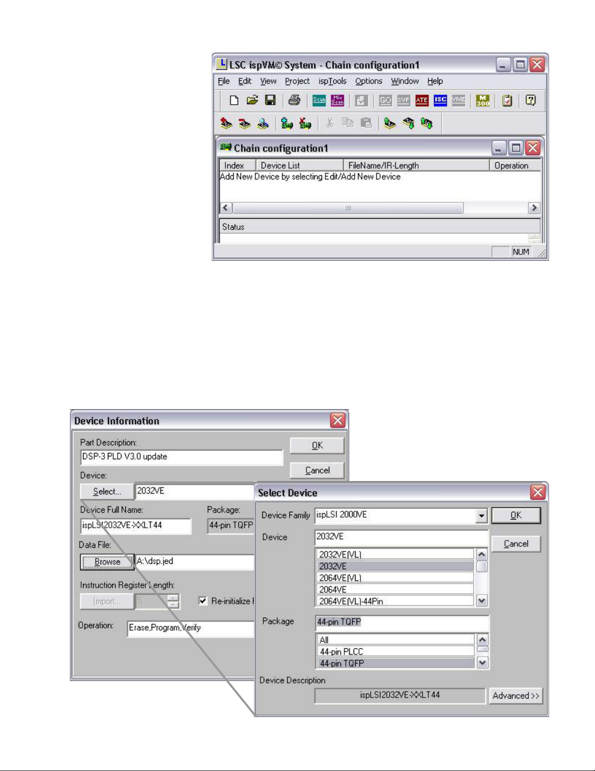
Figure 2. The ispVM™ System window.
Procedure: Updating the PLD
1. Start the ispVM™ System application. The following steps use screenshots of Version 13.0.1 installed on a Windows XP
Professional system; other versions of ispVM™ System may look different. A window like that in Figure 2 will appear.
2. Click Edit followed by Add Device.
3. Type an appropriate description in the Part Description box, then click Select (Figure 3). In the Device Family box select
ispLSI 2000VE. Click 2032VE in the Device list and 44-pin TQFP in the Package list. Click OK.
Figure 3. Select the ispLSI2032VE 44-pin
TQFP PLD, browse for the firmware file
and type a part description.
2DSP0007 rev. A
Page 3

4. In the Device Information window, click Browse and locate the current firmware file for the DSP-3 on your local or disk drive.
Click OK; the device, filename and operation in the main window will reflect the information just entered.
5. Click the Go icon on the
toolbar or click Download
from the Project menu. The
download process will take
approximately 5 seconds,
followed by a Pass indication
in the Status column of the
main window (Figure 4).
Procedure: Reassembly
and testing
1. The update is complete. Place
a red, 1/4”, color coding label
on the Lattice PLD with
reference designator U24.
2. Disconnect the external
power supply and the card
edge connector from the DSP3 module.
3. Place the two boards in the
chassis and fasten the four
screws that secure the board
assembly to the chassis.
4. Position the cover and attach
it with the four remaining
chassis screws.
5. Power the DSP-3 and verify that the module communicates through it’s serial port.
6. If your tests reveal proper operation, return the unit to use.
Figure 4. The operation is successful.
This bulletin is available for download from Service Bulletins page in the Tech Support section of the QSC Audio Web site:
http://www.qscaudio.com/support/technical_support/bulletins.htm
Contact information
If you need any further information regarding this service procedure, please contact QSC T echnical Services at the addresses or
numbers below.
Telephone: 1-800-772-2834 (within USA only)
+1 (714) 957-7150
Fax: +1 (714) 754-6173
E-mail: tech_support@qscaudio.com
Web sites: www.qscaudio.com (product info/support)
www.qscstore.com (on-line accessory and replacement component sales)
Postal and parcel address: QSC Audio Products, Inc.
Technical Services Group
1665 MacArthur Blvd.
Costa Mesa, CA 92626 USA
3DSP0007 rev. A
 Loading...