


Simplify
SANbox2-64 Fibre Channel Switch
Inst allation Guide
59043-01 A Page i

SANbox2- 64 Fibre Chan nel Switch
Installation Guide
Information furnished in thi s man ual is belie ved to be ac curate and rel iable . Howev er, QLogic Corp oration assu mes n o
responsibility for its use, nor for any infringements of patents or other rights of third parties which may result from its
use. QLogic Corporation reserves the right to change product specifications at any time without notice. Applications
described in this document for any of these products are for illustrative purposes only. QLogic Corporation makes no
representation nor warranty that such applications are suitable for the specified use without further testing or
modification. QLogic Corporation assumes no responsibility for any errors that may appear in this document.
QLogic, SANbox, SANbox2, SANblade, SANsurfer, and Multistage are trademarks or registered trademarks of
QLogic Corporation.
Java and Solaris are registered trademarks of Sun Microsystems, Inc.
Pentium III is a registered trademark of Intel Corporation.
Linux is a registered trademark of Linus Torvalds.
Microsoft, Windows NT, and Windows 2000, and Internet Explorer are trademarks of Microsoft Corporation.
NetScape Navigator is a registered trademark of Netscape Communications Corporation.
Red Hat is a registered trademark of Red Hat Software Inc.
All other brand and product names are trademarks or registered trademarks of their respective owners.
Document Revision History
Revision A, Release, March 2003
© 2000–2003 QLogic Corporation
First Printed: May 2001
All Rights Reserved Worldwide.
Printed in U.S.A.
QLogic Corporation, 6321 Bury Drive, Eden Prairie, MN 55346
Page ii 59043-01 A
(800) 342-7379 or (952) 932-4000

Table of Contents
Section 1 Introduction
1.1 Intended Audience.............................................................................................1-1
1.2 Related Ma te rials .............................. .. ............. ... ............. .. ............. ... ............. .. . 1-2
1.3 Safety N o ti ces............. .. ............. ... ............. .. ............. .............. .. ............. .. .......... 1-3
1.4 Sicherheitshinweise............................................................................................1-3
1.5 Notes informatives relatives à la sécurité...........................................................1-3
1.6 Communications Statements.............................................................................. 1-4
1.6.1 Federal Communications Commission (FCC) Class A Statement ............1-4
1.6.2 Canadian Department of Communications Class A
Compliance Statement .......................... .. ... ............. .. ............. ... ............. .. . 1-4
1.6.3 Avis de conformité aux normes du ministère des
Communications du Canada.................................. ...................................1-5
1.6.4 CE Statement ............................................................................................1-5
1.6.5 VCCI Class A Statement ............................. ..............................................1-6
1.6.6 BSMI Class A Statement........................................................................... 1-6
1.7 Laser Safety Information ....................................................................................1-7
1.8 Electrostatic Discharge Sensitivity (ESDS) Precautions....................................1-7
1.9 Access ib le P a rts..................... .. ............. ... ............. .. ............. ... ............. .. ............ 1-8
1.10 Pièces Accessibles.............................................................................................1-8
1.11 Zugängliche Teile...............................................................................................1-8
1.12 Technical Support . ..............................................................................................1-9
1.12.1 Availability..................................................................................................1-9
1.12.2 Training......................................................................................................1-9
1.12.3 Contact Information ................................................................................... 1-9
Section 2 General Description
2.1 Chassi s H a rd w a r e................ ............. .. ............. ... ............. .. ............. ... ............. .. . 2-2
2.2 Chassis Controls and LEDs ....................................... .................... ....................2-4
2.2.1 Maintenance Button...................................................................................2-5
2.2.1.1 Resetting a Switch............................................................................2-5
2.2.1.2 Placing the Switch in Maintenance Mode.......................... ...............2-5
2.2.2 Cha s si s L E D s............................. .. .............. .. ............. ............. ... ............. .. . 2-6
2.2.2.1 Input Power LED (Green).................................................................2-6
2.2.2.2 Heartbeat LED (Amber).................................................................... 2-6
2.2.2.3 Fan Fail LED (Amber)......................... .................. ..................... .......2-7
2.2.2.4 Over Temperature LE D (Am b e r) . ............. .. .............. .. ............. .. ........2-7
59043-01 A Page iii

SANbox2- 64 Fibre Chan nel Switch
Installation Guide
2.3 Fibre Channel Ports ...........................................................................................2-7
2.3.1 Small Form-Factor Pluggable (SFP) Transceivers................... .................2-8
2.3.2 Port Status LED.........................................................................................2-8
2.3.3 Port Modes............................................................................... .................2-9
2.3.3.1 Fabric Ports......................................................................................2-9
2.3.3.2 Translated Loop Port......................................................................2-10
2.3.3.3 Expansion Port ...............................................................................2-10
2.4 Ethernet Port .................................................................................................... 2-11
2.5 Serial Port.........................................................................................................2-12
2.6 Power Supply Modules.....................................................................................2-13
2.7 Fans .................................................................................................................2-14
2.8 Switch Management.........................................................................................2-15
Section 3 Planning
3.1 Devices...............................................................................................................3-1
3.1.1 Pub lic an d P ri va t e ............ .. .............. .. ............. .. .............. .. ............. .. .......... 3-1
3.1.2 Redundancy and Latency...................................................... .. ..................3-2
3.2 Multiple C h a ss is F a br ic s .......... ............. ... ............. .. ............. ... ............. .. ............ 3-4
3.2.1 Domain ID, Principal Priori ty, and Domain ID Lock................. ..................3-4
3.2.2 Common Topologies..................................................................................3-5
3.3 Performance....................................................................................................... 3-6
3.3.1 Distance..................................................................................................... 3-6
3.3.2 Bandwidth..................................................................................................3-7
3.3.3 Latency......................................................................................................3-7
3.4 Device Access.................................................................................................... 3-8
3.4.1 Soft Zone...................................................................................................3-9
3.4.2 Access Control Lis t H a rd Z o ne............ ............. .. ... ............. .. ............. ... .....3-9
3.4.3 Virtual Private Fabri c Hard Zones....................................................... ....3-10
3.5 Fabric Management.........................................................................................3-10
3.6 Fabric Security.................................................................................................3-11
Section 4 Installation
4.1 Site Requirements..................................... .. .......................... ......................... ....4-1
4.1.1 Fabric Management Workstation...............................................................4-1
4.1.2 Switch Power Requirements.....................................................................4-1
4.1.3 Environmental Conditions.......... ........................ ........................................4-2
4.2 Installing a Switch...............................................................................................4-2
4.2.1 Mount the Switch.......................................................................................4-3
4.2.2 Install SFP Transceivers............................................................................4-5
4.2.3 Connect the Switch to AC Power ............................................ ..................4-5
Page iv 59043-01 A

SANbox2-64 Fibre Channel Switch
4.2.4 Connect the Management Workstation to the Switch................................4-7
4.2.4.1 E thernet Connection........................ .......................................... .......4-8
4.2.4.2 S erial Connection.............................................................................4-8
4.2.5 Installing SANbox Manager...................................... .. .. ........................... ..4-9
4.2.6 SANsurfer Management Suite Disk - Windows Installation.....................4-10
4.2.7 SANsurfer Management Suite Disk - Linux Installation........................... 4-11
4.2.8 SANsurfer Management Suite Disk - Solaris Installation ........................4-12
4.2.9 SANbox2 Installation Disk - Windows Installation............................ .......4-13
4.2.10 SANbox2 Installation Disk - Linux Installation ......................................... 4-13
4.2.11 SANbox2 Installation Disk - Solaris Installation....................................... 4-13
4.2.12 Configure the Switch ............................................................................... 4-14
4.2.13 Configure the Ports.................................................................................. 4-15
4.2.14 Cable Devices to the Switch....................................................................4-15
4.3 Install Firmware................................................................................................4-16
4.3.1 Using SANbox Manager to Install Firmware............................................4-16
4.3.2 Using the CLI to Install Firmware ............................................................4-17
4.3.3 Usin g FTP a nd th e C L I to In sta ll F irmware ............ .. ............. .. .............. .. . 4-18
4.4 Poweri n g D o w n a Sw itch................. .. ............. .. .............. ............. .. ............. ... ...4 -1 9
Installation Guide
Section 5 Diagnostics/Troubleshooting
5.1 POST Diagnostics..............................................................................................5-1
5.1.1 Hea rt b ea t LED Blink Patterns.............. ............. .. .............. .. ............. ..........5-1
5.1.1.1 Normal (all pass)...............................................................................5-1
5.1.1.2 Maintenance Mode Pattern ..............................................................5-2
5.1.1.3 Internal Firm w a re Fa i lu re B lin k P a tte r n .............. ... ............. .. ............ 5-2
5.1.1.4 Fatal Error Blink Pattern ................................................................... 5-2
5.1.1.5 Configuration File System Error Blink Pattern.................................. 5-2
5.1.2 Port Status LED Indications.......................................................................5-5
5.1.2.1 E_Port Isolation ................................................................................5-6
5.1.2.2 Excessive Port Errors .......................................................................5-7
5.2 Chassis Diagnostics...........................................................................................5-9
5.2.1 Ove r Temperature LED is Illumi n a te d........... ............. .. .............. .. ............ 5-10
5.2.2 Input Power LED Is Extinguished............................................................5-10
5.2.3 Fan Fail LED is Illuminated......................................................................5-10
5.2.4 Output Power LED Is Extinguished..................................... ....................5-11
5.2.5 Power Supply Fault LED is Illuminated................................... ................5-11
5.3 Recovering a Switch......................................................................................... 5-12
5.3.1 Maintenance – Exit. ... ............. .. ............. .. .............. .. ............. .. .............. .. . 5-13
5.3.2 Maintenance – Image Unpack.................................................................5-13
5.3.3 Maintenance – Reset Network Co nf ig............ ............. ... ............. .. .......... 5-14
59043-01 A Page v

SANbox2- 64 Fibre Chan nel Switch
Installation Guide
5.3.4 Maintenance – Reset Password File.............. ............. ... ............. .. .. ........5-14
5.3.5 Maintenance – Copy Log Files. ...............................................................5-14
5.3.6 Maintenance – Remove Switch Config....................................................5-14
5.3.7 Maintenance – Remake Filesyste m ........................ .. ............. ... ............. . 5-14
5.3.8 Maintenance – Reset Switch...... ............. ... ............. .. ............. ... ............. . 5-14
Section 6 Removal/Replacement
6.1 SFP Transceivers............................................................................................... 6-1
6.2 CPU Module.......................................................................................................6-2
6.2.1 Removing the CPU Module..................................................................... ..6-3
6.2.2 Installing the CPU Module.........................................................................6-5
6.3 I/O Blades...........................................................................................................6-7
6.4 Cross-Connect Blades.....................................................................................6-11
6.4.1 Removing a CC Blade............................................................................. 6-12
6.4.2 Installing a CC Blade...............................................................................6-14
6.5 Power Supply Modules.....................................................................................6-16
6.5.1 Removing a Power Supply Module.........................................................6-16
6.5.2 Installing a Power Supply Module ...........................................................6-17
6.6 Fans .................................................................................................................6-18
6.6.1 Removing a Fan...................................................................................... 6-18
6.6.2 Installing a Fan ........................................................................................ 6-19
Appendix A Specifications
A.1 Performance.......................................................................................................A-1
A.2 Maintainability.....................................................................................................A-2
A.3 Fabric Management...........................................................................................A -3
A.4 Dimensions.........................................................................................................A-3
A.5 Electrical.............................................................................................................A-3
A.6 Environmental ....................................................................................................A-4
A.7 Regulatory Certifications....................................................................................A-4
A.8 Shortwave Laser SFP 1G/2G (multi-mode)........................................................A-5
A.9 Longwave Laser SFP 1G/2G (single-mode) ......................................................A-6
Appendix B Command Line Interface
B.1 Logging On to a Switch......................................................................................B-1
B.2 Command Syntax...............................................................................................B-2
B.3 Commands.........................................................................................................B-3
Admin Comma n d............. ............. ... ............. .. ............. ... ............. .. ............B-4
Alias Comman d ................. ... .. ............. .. ............. ... ............. .. ............. ... .....B-5
Config Comma n d........... ............. .. .............. .. ............. .. .............. .. ............. .B-7
Page vi 59043-01 A

SANbox2-64 Fibre Channel Switch
Installation Guide
Date Comman d .......................... .. .............. .. ............. .. .............. .. ............. .B-9
Fallback Command..................................................................................B-10
Help Comman d.......... ............. .. ............. .. .............. .. ............. .. .............. .. .B-11
History Command....................................................................................B-12
Hotswap Command.................................................................................B-13
Image Comma n d............. .. .............. .. ............. .. .............. .. ............. .. ........B-15
Lip Command..........................................................................................B-16
Passwd Comma n d ............ .............. .. ............. .. .............. .. ............. .. ........B-17
Ps Command...........................................................................................B-18
Quit Command ........................................................................................B-19
Reset Command........................................ .. ........................ ....................B-20
Set Command............ ............. .. ............. .. .............. .. ............. .. .............. .. .B-25
Set Config Com m a n d ...... .. .............. .. ............. .. .............. .. ............. .. ........B-27
Set Log Comman d...................... .. .............. .. ............. .. .............. .. ............B -3 5
Set Port Comm a nd. .............. .. ............. .. ............. ... ............. .. ............. ... ...B-38
Set Setup Com m a n d ..... .. ............. ... ............. .. ............. ... ............. .. ..........B-40
Show Command......................................................................................B-44
Show Config Command.................... .......................... .. ...........................B-55
Show Log Command............................ ...................................................B-58
Show Perf Command ..............................................................................B-60
Show Setup Command............................................................................B-62
Shutdown Command...............................................................................B-65
Test Command ........................................................................................B-66
Uptime Command............................. .. .. .. .. ...............................................B-69
User Comman d ............. .. .. .............. .. ............. .. .............. .. ............. .. ........B-70
Whoami Command......................... .. .......................................................B-72
Zone Command.......................................................................................B-73
Zoneset Command.................................... .......................... .. ..................B-77
Zoning Command.......................................................... ..........................B-79
Glossary
Index
Figures
Figure Page
2-1 SANbox2-64 64-Port Fibre Channel Switch...................................... ......................... .. ..2-2
2-2 Slot and Fibre Channel Port Numbering.................................................... .. ..................2-3
2-3 Chassis Controls and LEDS.................... ................................................. .. ....................2-4
2-4 Chassi s L E D s.......... .............. .. ............. .. .............. .. ............. .. .............. .. ............. .. ..........2-6
2-5 Fibre Channel Ports.......................................................................................................2-7
59043-01 A Page vii

SANbox2- 64 Fibre Chan nel Switch
Installation Guide
2-6 SFP Transceiver ............................................................................................................2-8
2-7 Ethernet Port................................................................................................................2-11
2-8 Serial Port ....................................................................................................................2-12
2-9 Power Supply Components..........................................................................................2-13
2-10 Fans............................................................................................................................. 2-14
3-1 Single Switch Fabric with Initiators and Targets ............................................................3-2
3-2 Dual Switch Fabric with Initiat ors and Targets............... .................... ............................3-3
4-1 SANbox2-64 Fibre Channel Switch.......... ............................................................... .......4-2
4-2 SANbox2-64 Rail Kit ...................................................................................................... 4-4
4-3 Ethernet and Serial Cable Connections...................................... ...................................4-7
5-1 Port Status LED ............................................................................................................. 5-5
5-2 Port Status LED Indications ........................................................................................... 5-5
5-3 Chassis and Power Supply LEDs..................................................................................5-9
6-1 Removing the CPU Module.............................. .. ............................. .. .............................6-4
6-2 Removing an I/O Blade..................................................................................................6-9
6-3 CC Blade Slots................................................................... .................... .................... ..6-11
6-4 Switch C o v e r R e m o va l.......... .. ............. .. .............. .. ............. .. .............. ............. .. .......... 6-13
6-5 CC Blade Removal........................................................ ........................... .. .. ................6-13
6-6 Installin g a C C B la d e...................... .. ............. .. ............. ... .. ............. .. .............. .. ............ 6-14
6-7 Removing a Power Supply Module..............................................................................6-17
6-8 Removing a Fan...........................................................................................................6-18
Tables
Table Page
2-1 Serial Port Pin Identification....................................................................................... ..2-12
3-1 Port-to-Port Transmission Combinations....................................................................... 3-7
3-2 Port-to-Port Latency.......................................................................................................3-7
4-1 Management Workstation Requirements.......................................................................4-1
6-1 Marginal Operating Configurations ................................................................................6-1
B-1 Commands Listed by Authority Level.............................................................................B-3
B-2 Switch Configur a tion Defaults............ ............. .. .............. .. ............. .. .............. .. ............B -2 1
B-3 Port Configuration Defaults..........................................................................................B-21
B-4 Alar m Th r e sh o ld C o n fig u r a tio n D e fa u lt s ................ .. ............. .. .............. .. .. ............. ... ...B-22
B-5 SNM P C o n fig u ration Defau lt s ................ ... ............. .. ............. .. .............. .. ............. .. ......B-23
B-6 System Configuration Defaults.....................................................................................B-24
B-7 Set C o n fig P o rt Pa r ameters ........... ............. .. ............. .. .............. .. ............. .. .............. .. .B-27
B-8 Set C o n fig S w it ch P a ra me ters ........... .. .. .............. .. ............. .. .............. .. ............. .. ........B-29
B-9 Set C o n fig T h re s h o ld Pa r a m e te r s.......... ... ............. .. ............. .. ... ............. .. ............. ... ...B-30
B-10 Set Config Zoni n g Pa r ameters.. .. ... ............. .. ............. .. .............. .. ............. .. .............. .. .B-31
B-11 SNMP Configu r a tio n S e tt in g s ............ ............. .. .............. .. ............. .. .............. .. ............B -4 0
B-12 System Configuration Settings.....................................................................................B-41
B-13 Show Port Parameters.................................................................................................B-46
Page viii 59043-01 A

Section 1
Introduction
This manual describes the features and installation of the SANbox2-64 Fibre
Channel switch, firmware version 1.5. This manual is organized as follows:
■ Section 1 describes the i ntended audience, related mater ials, safety notices ,
communications statement s, laser safety information, elec trostatic discharge
sensitivity precautions , accessible parts, and technical support.
■ Section 2 is an overview of the switch. It describes indicator LEDs and all
user controls and connections.
■ Section 3 describes the factors to consider when planning a fabric.
■ Section 4 explains how to install and configure the switch.
■ Section 5 describes the diagnosti c methods and tr oubleshooting
procedures.
■ Section 6 describes the removal/replacement procedures for all field
replaceable units (FRUs).
■ Appendix A lists the switch specifications.
■ Appendix B describes the Command Line Interface.
Please read the communications statements and laser safety information later in
this section. Use this manual with the SANbox2-64 Switch Management User’s
Guide.
1.1
Intended Audience
This manual introduces users to the switch and explains its installation and
service. It is intended for users who are responsible for the installation and
servicing of network equipment.
59043-01 A 1-1

1 – Introduction
Related Materials
1.2
Related Materials
The following manuals and materials are referenced in the text and/or provide
additional information.
■ SANbox2-64 Switch Management User’s Guide, Publication Number
59048-01.
■ Fibre Channel-Arbitrated Loop (FC-AL-2) Rev. 6.8.
■ Fibre Channel-Private Loop SCSI Direct Attach (FC-PLDA)
NCITS TR-19:1998
■ Fibre Channel-10-bit Interface Rev. 2.3.
■ Definitions of Managed Objects for the Fabric El eme n t in Fibre Channel
Standard (draft-ietf-ipfc-fabric-element-mib-04.txt).
The Fibre Channel Standards are available from:
Global Engineering Documents, 15 Inverness Way East, Englewood, CO
80112-5776 Phone: (800) 854-7179 or (303) 397-7956
Fax: (303) 397-2740.
1-2 59043-01 A

1.3
Safety Notices
A Warning notice indicates the presence of a hazard that has the potential of
causing personal injury.
4-3, 4-5, 6-2, 6-8, 6-12, 6-15, 6-16, 6-18
A Caution notice indicates the presenc e of a hazard that has the potential of
causing damage to the equipment.
4-3, 5-14, 6-2, 6-4, 6-8, 6-11, 6-16, 6-18
1.4
Sicherheitshinweise
Ein Warnhinweis weist auf das Vorhandensein einer Gefahr hin, die
möglicherweise Verletzungen zur Folge hat.
4-3, 4-6, 6-2, 6-8, 6-12, 6-15, 6-16, 6-18
Ein Vorsichtshinweis weist auf das Vorhandensein einer Gefahr hin, die
möglicherweise Geräteschäden zur Folge hat.
1 – Introduction
Safety Notices
4-3, 5-14, 6-2, 6-4, 6-8, 6-11, 6-16, 6-18
1.5
Notes informatives relatives à la sécurité
Une note informative Avertissement indique la présence d’un risque pouvant
entraîner des blessures.
4-3, 4-5, 6-2, 6-8, 6-12, 6-15, 6-16, 6-18
Une note informative Attention indiqu e la p résence d’un risqu e pouvant entraîner
des dégâts matériels.
4-3, 5-14, 6-2, 6-4, 6-8, 6-11, 6-16, 6-18
59043-01 A 1-3

1 – Introduction
Communications Statements
1.6
Communications Statements
The following statement s apply to this product. The statement s for other products
intended for use with this product appear in thei r accompanying manuals.
1.6.1
Federal Communications Commission (FCC) Class A Statement
This equipment has been tested and found to comply with the limits for a Class A
digital device, pur suant to Part 15 of the FCC Rules. These limits are designed to
provide reasonable protection agai nst harmful interference when t he equipment is
operated in a commercial environment. This equipment gener ates, use s, and can
radiate radio frequency energy, and, if not installed and used in accordanc e with
the instruction manual, may cause harmful inter ference to radio communications.
Operation of this equipment in a residential area may cause unacceptable
interference, in which case the user wil l be required to correct the interference at
their own expense.
Neither the provider nor the manufacturer is responsible for any radio or tel evision
interference caused by unauthorized changes or modifications to this equipment.
Unauthorized changes or modifications could void the user’s authority to operate
the equipment.
This device complies with Part 15 of the FCC Rules. Operation is subject to the
following two conditions:
■ This device may not cause harmful interference, and
■ This device must accept any interference received, including interference
that may cause undesired operation.
1.6.2
Canadian Department of Communications Class A Compliance Statement
This equipment does not exceed Class A limits for radio emissions for digital
apparatus, set out in Radio Interfer ence Regulation of the Canadian Department
of Communications. Operation in a residential area may cause unacceptable
interference to radio and TV reception req uiring the owner or operator to take
whatever steps necessary to correct the interference.
1-4 59043-01 A

1 – Introduction
1.6.3
Communications Sta tem ents
Avis de conformité aux normes du ministère des Communications du Canada
Cet équipement ne dépasse pas les limites de Classe A d'émission de bruits
radioélectriques por les appareils numériques, telles que prescrites par le
Réglement sur le brouillage radioélectrique établi par le ministère des
Communications du Canada. L'exploitation faite en milieu résidentiel peut
entraîner le brouillage des réceptions radio et télé, ce qui obligerait le propriétaire
ou l'opérateur à prendre les dis positi ons nécwssai res pour en éli miner les causes .
1.6.4
CE Statement
The CE symbol on the equipment indicates that this system complies with the
EMC (Electromagnetic Compatibility) directive of the European Community (89/
336/EEC) and to the Low Voltage (Safety) Directive (73/23/ EEC). Such marking
indicates that this system meets or exceeds the following technical standards:
■ EN60950/A11:1997 – “Safety of Information Technology Equipment,
Including Electrical Business Equip ment”.
■ EN60825-1/A11:1996 – “Safety of Laser Products, Part 1.
■ EN55022:1998 – “Limits and Methods of Measurement of Radio
Interference Characteristics of Information Technology Equipment”.
■ EN 55024-1:1998 – “Electromagnetic compatibility - Generic immunity
standard Part 1: Residential commercial, and light industry.”
❑ IEC1000-4-2:1995 – “Electrostat ic Discharge Immunity Test”
❑ IEC1000-4-3:1995 – “Radiated, Radio-Frequency, Electromagnetic
Field Immunity Test”
❑ IEC1000-4-4:1995 – “Electrical Fast Transient/Burst Immunity Test”
❑ IEC1000-4-5:1995 – “Surge Immunity Test”
❑ IEC1000-4-6:1996 – “Immunity To Conducted Disturbances, Induced
By Radio-Frequency Fields”
❑ IEC1000-4-8:1993 – Power Frequency Magnetic Field Immunity Test”
❑ IEC1000-4-11:1994 – “Voltage Dips, Short Interruptions And Voltage
Variations Immunity Tests”
■ EN61000-3-2:1995 – “Limits For Harmonic Current Emissions (Equipment
Input Current Less Than/Equal To 16 A Per Phase)” Class A
■ EN61000-3-3:1995 – “Limitation Of Voltage Fluctuations And Flicker In Low-
Vol tage Supply Systems For Equipment With Rated Current Less Than Or
Equal To 16 A”
59043-01 A 1-5

1 – Introduction
Communications Statements
1.6.5
VCCI Class A Statement
This is a Class A product based on the standard of the Voluntary Control Council
For Interference by Information Technology Equipment (VCCI). If this equipment
is used in a domestic environment, radio disturba nce may arise. When such
trouble occurs, the user may be required to take corrective actions.
1.6.6
BSMI Class A Statement
Warning:
This is a Class A product. In a domestic environment, thi s product may cause
radio interference in which case the user will be required to take adequate
measures.
1-6 59043-01 A

1.7
Laser Safety Information
This product may use Class 1 laser optical transceivers to communicate over the
fiber optic conductors. The U.S. Department of Health and Human Services
(DHHS) does not consider Class 1 lasers to be hazardous. The International
Electrotechnical Commission (IEC) 825 Laser Saf ety S tandard requi res labeling in
English, German, Finnish, and French stating that the product uses Class 1
lasers. Because it is impractical to label the transceivers, the following label is
provided in this manual.
1 – Introduction
Laser Safety Information
1.8
Electrostatic Discharge Sensitivity (ESDS) Precautions
The assemblies used in the switch chassis are ESD sensitive. Observe ESD
handling procedures when handling any assembly used in the switch chassis.
59043-01 A 1-7

1 – Introduction
Accessible Parts
1.9
Accessible Parts
The Field Replaceable Units (FRUs) in the SANbox2-64 swi tch are:
■ Small Form-Factor Pluggable (SFP) optical tr ansceivers
■ CPU module
■ I/O blades
■ Power supply modules
■ Fans
Refer to Section 6 Removal/Replacement for more infor ma t io n .
1.10
Pièces Accessibles
Les pièces remplaçables, Field Replaceable Units (FRU), du commutateur
SANbox2-64 Fibre Channel Switch sont les suivantes:
■ Interfaces aux media d’interconnexion appelés SFP transcei vers.
■ Module d'UC
■ Lames d'entrée/sortie
■ Modules d'alimentation d'énergie
■ Ventilateurs
Se reporter à la Section 6 Removal/Replacement (Procédures de retrait et
remplacement) pour plus de renseignements.
1.11
Zugängliche Teile
Nur die folgenden Teile im SANbox2-64 Fibre Channel Switch können
kundenseitig ersetzt werden:
■ Schnittstellen für die Zwischenverbindungsträger, SFP transceivers
genannt.
■ Zentraleinheitsmodule
■ Blätter Des Einganges/Ausganges
■ Netzteilmodule
■ Gehäuselüfte
Weitere Informationen finden Sie im Abshcnitt 6 (Ausbauen der ersetzbaren
Teile).
1-8 59043-01 A

1.12
Technical Support
Customers should contact their authorized maintenance provider for technical
support of their QLogic switch products. QLogic-direct customers may contact
QLogic Technical Support; others will be redirected to their author ized
maintenance provider.
Visit the QLogic switch support Web site listed in Contact I nformation f or the latest
firmware and software updates.
1.12.1
Availability
QLogic Technical Support is available from 7:00 AM to 7:00 PM Central Standard
Time, Monday through Friday, excluding QLogic-observed holidays.
1.12.2
Training
QLogic offers the followi ng technical training courses:
1 – Introduction
Technical Support
■ Switch Cert if ic a tio n
■ HBA Certification
Each course is available at the train ing faci lity in Eden Prairi e, MN or at your local
facility. All courses include a Fibre Channel overview and sections on installation,
maintenance, and topology solutions. Each st udent receives a set of manuals and
a CD-ROM containing course training materials. Upon successful completion of
the training, Qlogic awards a certificate identifying the student as a Certified
SANbox® or SANblade® Professional.
1.12.3
Contact Information
Address: QLogic Switch Products Inc.
Telep hone : +1 952-932-4040
Fax: +1 952-932-4018
Email:
Technical Service
Technical Training
6321 Bury Drive
Eden Prairie, Minnesota 55346
USA
support@qlogic.com
tech.training@qlogic.com
Switch Support Web Site: support.qlogic.com
59043-01 A 1-9

1 – Introduction
Technical Support
Notes
1-10 59043-01 A

Section 2
General Description
This section describes the features and capabilities of the SANbox2-64 Fibre
Channel switch. The following topics are described:
■ Chassis configuration
■ Chassis controls and LEDs
■ Fibre channel ports
■ Ethernet port
■ Serial port
■ Fabric management
Fabrics are managed with the SANbox Manager switch management application
(version 1.05) and the Command Line Interface (CLI). Refer to
Appendix B Command Line Interface for more infor m a ti o n . R ef e r to th e SANbox2-
64 Switch Management User’s Guide for information about using the SANbox
Manager application.
59043-01 A 2-1
2 – General Description
Chassis Hardware
2.1
Chassis Hardware
The SANbox2-64 switch is set of up to eight 8-port I/O blades. Each I/O blade is
interconnected with all other I/ O blades through the backplane whi ch is supported
by four cross-connect ASICs. A CPU module provides configuration, monitoring,
data path management, and con trol functions.
The base SANbox2-64 switch is configured as a 16-port swit ch. The 16-port
switch is equipped with 2 I/O blades, 2 power supply modules, and a CPU
module. To maintain proper air flow and cooling in the 16-port swi tch, inserts are
installed in empty I/O blade slots. You can expand the switch by installing
additional I/O blades up to a total of eight. The 64-port switch is equipped with
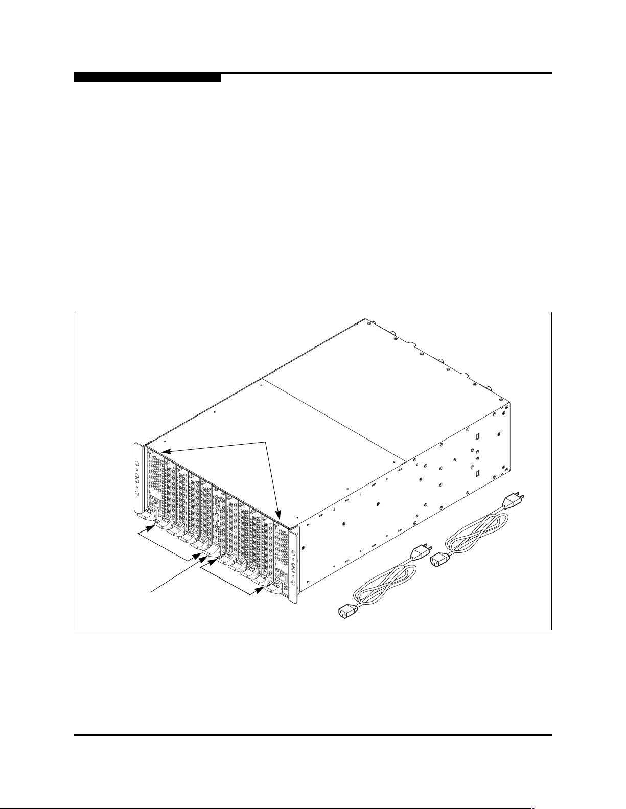
8 I/O blades, 2 power supply modules, and a CPU module as shown in Figure 2-1.
Refer to Section 6 Removal/Replacement for the marginal operating
configurations.
I/O Blades
CPU Module
Power Supply
Modules
I/O Blades
Figure 2-1. SANbox2-64 64-Port Fibre Channel Switch
2-2 59043-01 A
2 – General Description
Chassis Hardware
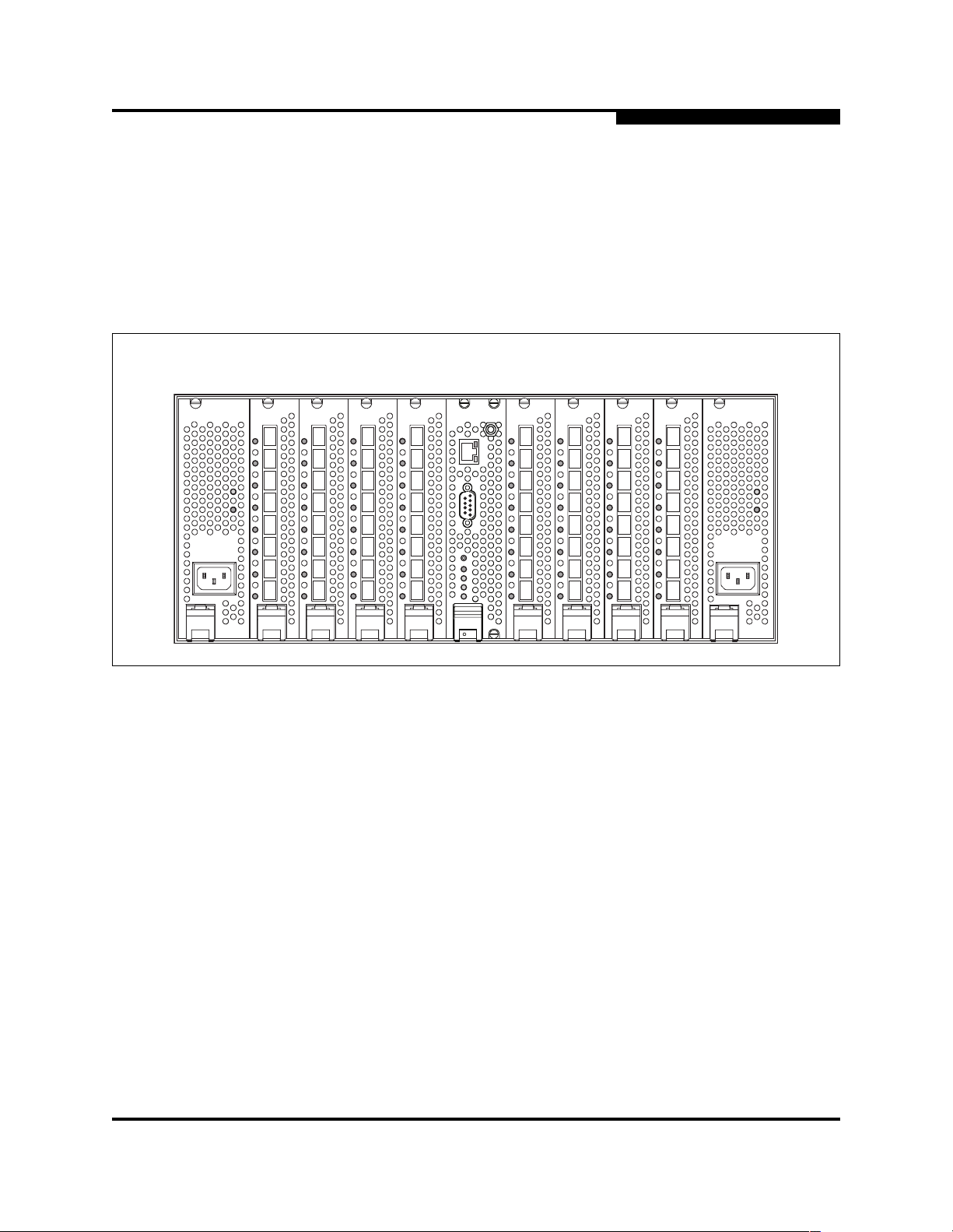
There are 11 slots numbered #0–#10 as shown in Figure 2-2. Power supply
modules occupy slots #0 and #10. The CPU module occupies slot #5. I/O blades
occupy slots #1–#4 and #6–#9. The Fibre Channel ports on the I/O blades are
numbered 0–63 from top to bottom according to slot number as shown in
Figure 2-2. For example, the por ts 0–7 are always assoc iated with the I/ O blade in
slot #1; ports 8–15 are always associated with slot #2, and so on. For example, if
there were no I/O blade in slot #1, I/O blade #2 would retain the 8–15 port
numbering.
Slot #0 Slots #1–#4 Slot #5 Slots #6–#9 Slot #10
0
1
2
3
4
5
6
7
8
16
9
17
10
11
12
13
14
15
18
19
20
21
22
23
24
25
26
27
28
29
30
31
32
33
34
35
36
37
38
39
40
41
42
43
44
45
46
47
48
49
50
51
52
53
54
55
56
57
58
59
60
61
62
63
Figure 2-2. Slot and Fibre Channel Port Numbering
The base SANbox2-64 switch comes with I/O blades in slots 1 and 9. You can
expand the switch to 24, 32, 40, 48, 56, or 64 ports by installing 1, 2, 3, 4, 5, or 6
additional I/O blades. Install additional I/O blades in open slots in the following
order:
■ 3rd I/O blade in slot 2
■ 4th I/O blade in slot 8
■ 5th I/O blade in slot 3
■ 6th I/O blade in slot 7
■ 7th I/O blade in slot 4
■ 8th I/O blade in slot 6
59043-01 A 2-3
2 – General Description
Chassis Controls and LEDs
2.2
Chassis Controls and LEDs
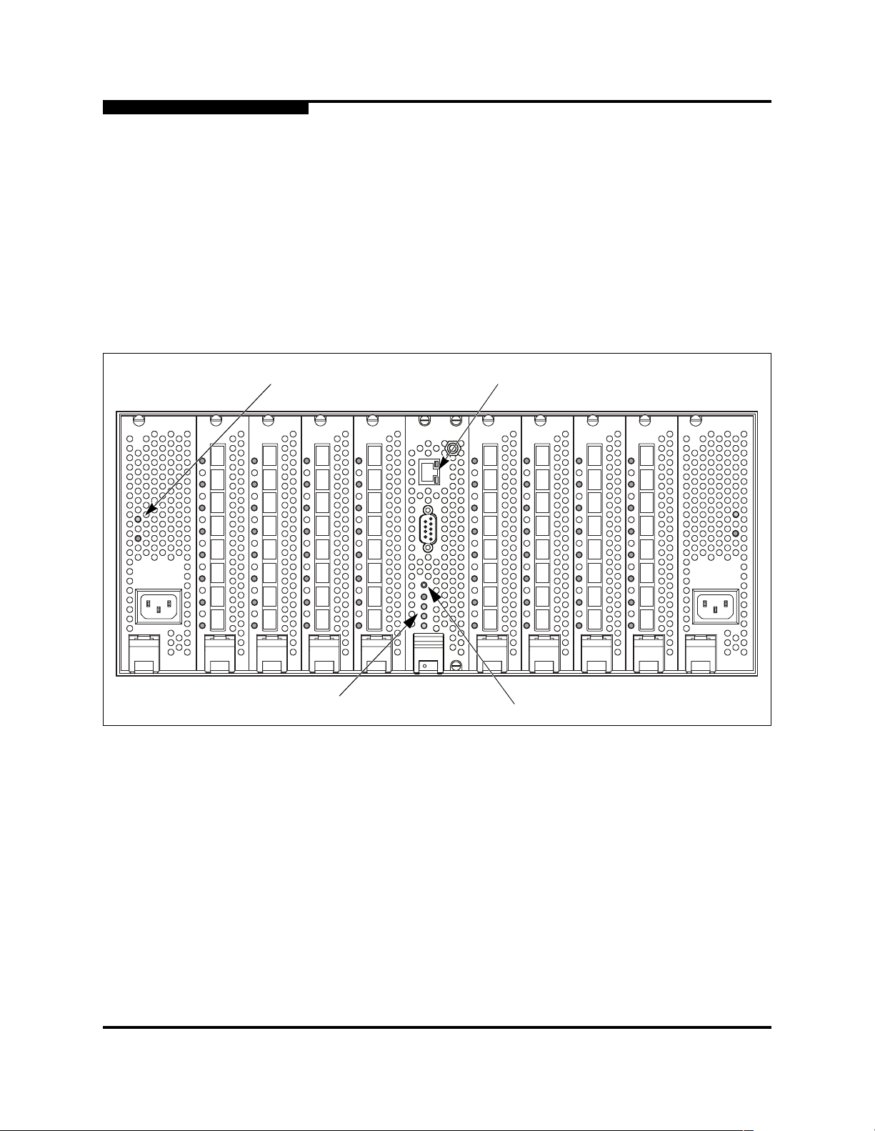
The Maintenance button on the CPU module, as shown in Figure 2-3, is the only
chassis control. Power is applied to the switch logic circuitry when one or both
power supply modules are connected to a 110 or 230 VAC power source. The
chassis LEDs are located on the CPU module and provide status information
about the condition of the swit ch. The chassis LEDs include the In put Power LED,
Heartbeat LED, Over Temperature LED, and the Fan Fail LED. Refer to ”Power
Supply Modules” on page 2-13 for information about power supply LEDs and to
”Port Status LED” on page 2-8 for information about the Port Stat us LED.
Power
Supply LEDs
Chassis LEDs
Ethernet
Port LEDs
Maintenance
Figure 2-3. Chassis Controls and LEDS
Button
2-4 59043-01 A

2.2.1
Maintenance Button
The Maintenance button is dual function control on the CPU module that resets
the switch or places the swi tch in maint enance mode. Maint enance mode se ts the
IP address to 10.0.0.1 and provides access to the switch for maintenance
purposes when flash memory or the resident configuration file is corrupted. Refer
to ”Recovering a Switch” on page 5-12 for information about maintenance mode.
2.2.1.1
Resetting a Switch
To reset the switch, use a pointed tool to press and release (less than 4 seconds)
the Maintenance button. The switch will respond as follows:
1. All of the chassis LEDs will illuminate and then extinguish leaving only the
Input Power LED illuminated.
2. After approximately 1 minute, the power-on self test begins illuminating all
chassis LEDs.
2 – General Description
Chassis Controls and LEDs
3. When the POST is complete, the chassis LEDs extinguish leaving the Input
Power LED illuminated and the Heartbeat LED flashing once per second.
2.2.1.2
Placing the Switch in Maintenance Mode
To place the switch in maintenance mode, do the following:
1. Isolate the switch from the fabric.
2. Press and hold the Maintenance button with a pointed tool for about 4
seconds. When the Input Power LED alone is illuminated, release the
button.
3. After approximately 1 minute, the power-on self test begins illuminating all
chassis LEDs.
4. When the POST is complete, the chassis LEDs extinguish leaving the Input
Power LED and the Heartbeat LED illuminated. The Heartbeat LED
illuminates continuously while the switch is in maintenance mode.
To exit maintenance mode and return to normal operation, press and release the
Maintenance button to reset the switch.
59043-01 A 2-5
2 – General Description
Chassis Controls and LEDs
2.2.2
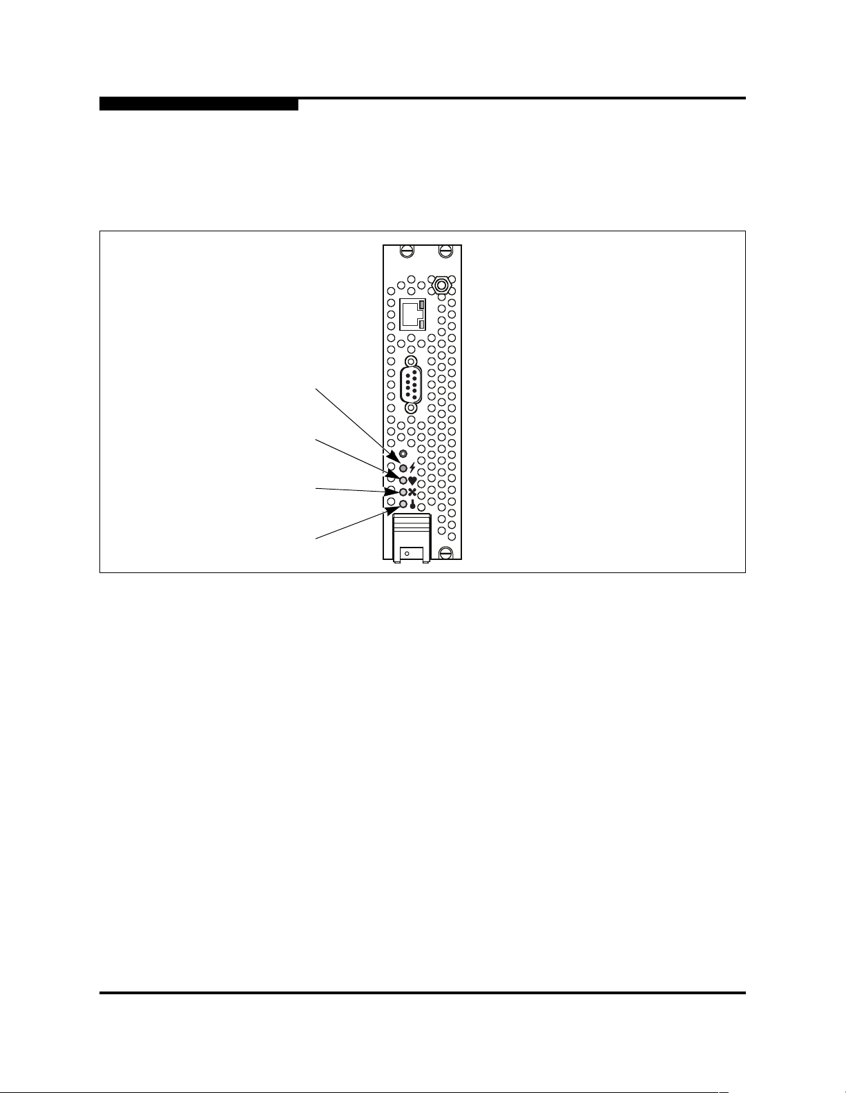
Chassis LEDs
The chassis LEDs shown in Figure 2-4 provide status information about switch
operation.
Input Power LED
(Green)
Heartbeat LED
(Amber)
Fan Fail LED
(Amber)
Over Temperature LED
(Amber)
2.2.2.1
Input Power LED (Green)
The Input Power LED indicates the volt age st atus at the switch logi c circuitr y. This
LED illuminates when the switch logic circuitr y is receiving the proper DC
voltages.
2.2.2.2
Heartbeat LED (Amber)
The Heartbeat LED indicates the status of the int ernal switch processor and the
results of Power On Self Tests (POSTs). Following a normal power-up, the
Heartbeat LED blinks about once per second to indicate that the switch passed
the POST and that the internal s witch processor is running. In maintenance mode,
the Heartbeat LED illuminates continuously. Refer to ”Heartbeat LED Blink
Patterns” on page 5-1 for more information about Heartbeat LED blink patterns.
Figure 2-4. Chassis LEDs
2-6 59043-01 A
2.2.2.3
Fan Fail LED (Amber)
The Fan Fail LED indicates operational status of all fans. This LED illuminates if
the speed of any fan falls below the normal range. Removing a fan will not
illuminate the Fan Fail LED. Refer to Section 5 Diagnostics/Troubleshooting for
information about troubleshooting fan failure conditions.
2.2.2.4
Over Temperature LED (Amber)
The Over Temperature LED provides st atus i nfor mation about the ai r t emperature
inside the switch. This LED illuminates to indicate that the switch logic circuitry i s
overheating. Refer to Section 5 Diagnostics/Troubleshooting for information about
troubleshooting over temperature conditions.
2.3
Fibre Channel Ports
Each I/O blade has eight Fibre Channel ports that are interconnected with al l other
I/O blades through the backplane. Fibr e Channel port s are numbered ac cording to
the slot in which the I /O blade resi des. Each port is served by a Small For m-Factor
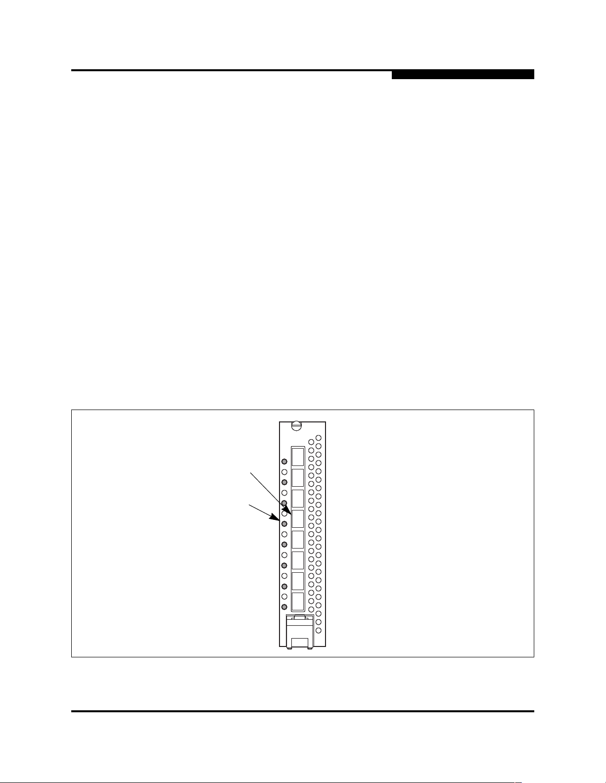
Pluggable (SFP) transceiver. A Port Status LED, located to the lef t of each port as
shown in Figure 2-5, provides port login and activity status inform ation. Port
modes configure the ports to communicate with public devices, private devices,
and other switches.
2 – General Description
Fibre Channel Ports
Port
Port St atus
LED
Figure 2-5. Fibre Channel Ports
59043-01 A 2-7

2 – General Description
Fibre Channel Ports
2.3.1
Small Form-Factor Pluggable (SFP) Transceivers
An SFP transceiver , like the one shown in Figure 2-6, converts electrical signal s to
and from optical laser signals to transmit and receive data. SFP transceivers plug
into the ports; duplex fiber optic cables plug into the transceivers which then
connect to the devices. A port is capable of transmitting at 1 Gbps or 2 Gbps;
however, the transceiver must be capable of 2 Gbps for the port to deliver at that
rate.
The SFP transceivers are hot swappable. This means that you can re mov e or
install an SFP transceiver while the swi tch is operat ing without harming the swit ch
or the transceiver. However, communication with the connected device will be
interrupted. Refer to Section 6 Removal/Replacement for informati on ab out
installing and removing SFP optical trans ceivers.
2.3.2
Port Status LED
The Port Status LED is a two-color LED that indicates both logged-in (or loop
initialization) status and when the port is transmitting or receiving frames.
Following a successful port login or l oop initialization, the Port Status LED
illuminates green. When the port begins transmitting or receiving frames, the Port
Status LED illuminates amber for 50 milliseconds as each frame passes . Thi s
makes it possible to observe the transmission of a single frame. The Port Status
LED remains illuminated as long as the port is initialized or logged in. If the port
connection is broken or an error occurs that disables the port, the Port S tatus LED
will flash green. Refer to ”Port Status LED Indications” on page 5-5 for more
information about the Port Status LED.
Figure 2-6. SFP Transceiver
2-8 59043-01 A

2.3.3
Port Modes
2 – General Description
Fibre Channel Ports
SANbox2-64 switches support the following port modes:
■ Generic ports (GL_Port and G_Port)
■ Fabric ports (FL_Port and F_Port)
■ Translated loop ports (TL_Port)
■ Expansion ports (E_Port)
Switches come from the factory with all ports configured as GL_Ports. GL_Port s
self-configure in the following ways:
■ FL_Port when connected to a loop of public devices
■ F_Port when connected to a single public device. If the devi ce is a single
device on a loop, the GL_Port will attempt to configure first as an F_Port,
then if that fails, as an FL_Port.
■ E_Port when connected to another FC-SW-2 compliant switch
G_Ports self-configure in the following ways:
■ F_Port when connected to a public device
■ E_Port when connected to another FC-SW-2 compliant switch
A TL_Port supports private loop devices and must be configured explicitly. Refer
to the SANbox2-64 Switch Management User’s Guide for more information about
defining port modes.
2.3.3.1
Fabric Ports
An FL_Port can support a loop of up to 126 public devices. An FL_Port can also
configure itself during the fabric login process as an F_Port when connected to a
single public device (N_Port).
59043-01 A 2-9

2 – General Description
Fibre Channel Ports
2.3.3.2
Translated Loop Port
A TL_Port supports a loop of up to 125 private initiator devices or up to 124
private target devices with the ability to communicate wit h “off-loop” devices. This
includes public fabric devices and priv ate devices on other TL_Ports. TL_Ports
connect to devices that conform to the Fibre Channel-Private Loop SCSI Direct
Attach (FC-PLDA) standard. Devices connected to TL_Ports are registered with
the Name Server.
A TL_Port acts as a proxy for the off-loop device translating private frames into
and from public frames. Each TL_Port can proxy up to 63 of f-l oop initi ator devices
or up to 64 off-loop target and ini ti ator devices. The set of off-loop devices ar e
maintained in the TL_Port’s translation entries list.
■ For a TL_Port connected to private target devices, the switch firmware
automatically creates an entry in the translation entries list for each of f-loop
initiator device that attempt s to est ablish communication. Sof t or VPF zoning
can be used to limit the number of potential initiator s to 63. Zone
membership must be done by worldwide name, or domain ID and port ID.
■ For a TL_Port connected to private initiator devices, the switch firmware
2.3.3.3
Expansion Port
E_Ports enable you to expand th e fabric by connecting SANbox2-64 switches wi th
other FC-SW-2 compliant switches . SANb ox2-64 switches self-discover all interswitch connections. Refer to ”Multiple Chassis Fabrics” on page 3-4 for more
information about multiple chassis fab ri cs.
automatically creates an entry i n the translat ion entries li st for up to 64 t arget
and initiator devices that are members of t he same soft or VPF zone. Zone
membership must be done by worldwide name, or domain ID and port ID.
2-10 59043-01 A

2.4
Ethernet Port
The Ethernet port is a RJ-45 connector located on the CPU module as shown in
Figure 2-7. This port require s a 10/100BASE-T cabl e and provi des a connection
for a management workstation, such as a PC, a Solaris ™ workstation, or a Linux®
workstation, through which to manage the switch. You can manage the switch
over an Ethernet connection using SANbox Manager, the Command Line
Interface (CLI), or SNMP. The switch through which a fabric is managed is called
the fabric management switch.
The Ethernet port has t wo L EDs: a L ink Status LED and an Activity LED. The Link
Status LED illuminates green to indicate that an Ethernet connect ion has been
established with a management workst ation. The Activity LED illuminates amber
to indicate that dat a is be ing t ransmit ted o r recei ved over the Et her net connect ion .
2 – General Description
Ethernet Port
RJ-45 Ethernet Port
Figure 2-7. Ethernet Port
Link Status LED
(Green)
Activity LED
(Amber)
59043-01 A 2-11

2 – General Description
Serial Port
2.5
Serial Port
The SANbox2-64 switch is equipped with an RS-232 serial port for maintenance
purposes. The serial port is located on the CPU module as shown in Figure 2-8.
Serial Port
1
6
5
9
Figure 2-8. Serial Port
The serial port connector requires a null-mod em F/F DB9 cable. The pins on the
switch RS-232 connector, shown in Figure 2-8, are identified i n Table 2-1. Refer to
”Connect the Management Workst at ion to the Switch” on p age 4-7 for information
about connecting the management workstation through the serial port.
Table 2-1. Serial Port Pin Identification
Pin Number Description
1 Carrie r Detect (DCD)
2 Receive Data (RxD)
3 Transmit Data (TxD)
4 Data Terminal Read y (DT R)
5 Signal Ground (GND)
6 Data Set Ready (DSR)
7 Request to Send (RTS)
8 Clear to Send (CTS)
9 Ring Indicator (RI)
2-12 59043-01 A

2.6
Power Supply Modules
The power supply modules convert standard 110 or 230 VAC to DC voltages for
the various switch circuits. Each power supply module has an AC power
receptacle and two status LEDs as shown in Figure 2-9. Each power supply
module is capable of providing all of the switch’s power needs. During normal
operation, each power supply provides half of the demand. If one power supply
goes offline, the second powe r supply steps up and provides the difference. After
connecting a power supply to an AC voltage source, the power suppl y is
energized and the DC voltages are delivered to the switch logic circuitry.
2 – General Description
Power Supply Modules
Output Power LED
(Green)
Power Supply
Fault LED
(Amber)
AC Power
Receptacle
Figure 2-9. Power Supply Components
The power supplies are hot pluggable and interchangeabl e. Hot pluggable means
that you can remove and replace one of the two operating power supplies while
the switch is in operation without disrupting service. Refer to Section 6 Removal/
Replacement for information about replacing a power supply.
Each power supply has two st atus LEDs: a Power Supply Fault LED (amber) and
an Output Power LED (green). The Power Supply Fault LED illuminates to
indicate a power supply fault. Possible power supply faults include high
temperature, high or low input voltage, high or low output voltage, and high
current. Refe r to Section 5 Diagnostics/Troubleshooting for informati on about
troubleshooting power supply fault conditions.
The Output Power LED illuminates to indicate that the power supply is produci ng
DC voltage at the proper levels.
59043-01 A 2-13
2 – General Description
Fans
2.7
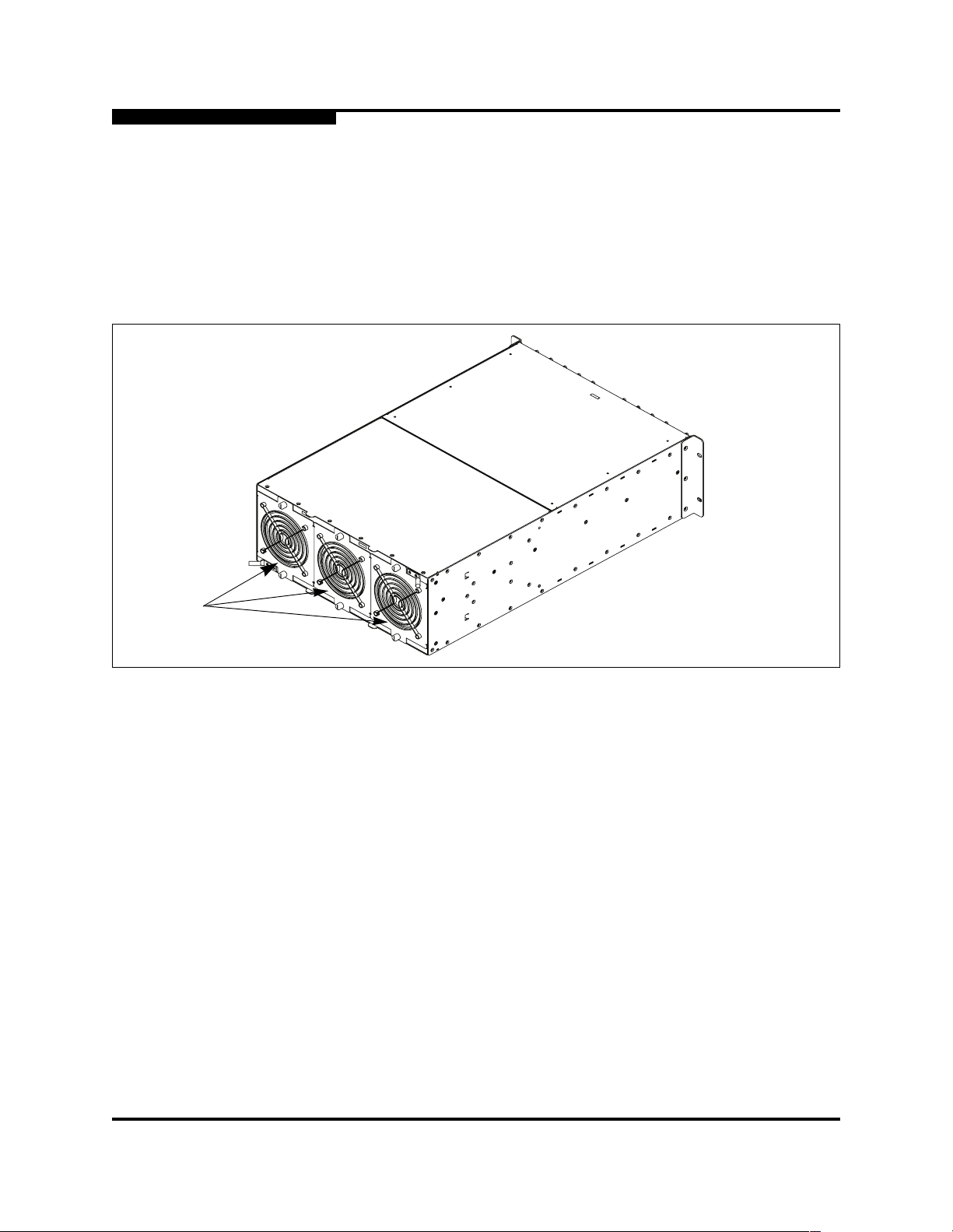
Fans
The switch is equipped wit h three fans as shown in Figure 2-10. If one of the fans
should fail, the other two f ans ar e cap abl e of provi ding t he neces sary cool ing unt il
the failed fan can be replaced. The fans are hot pluggable and interchangeable.
Refer to ”Fans” on page 6-18 for information about removing and replacing the
fans. Air flow can be back-to-front or front-t o-back depending on the model.
Fans
Figure 2-10. Fans
2-14 59043-01 A

2.8
Switch Management
SANbox Manager is a workstation-based Java® application that prov ides a
graphical user interface for fa bric management. This application runs on a
Windows®, Solaris, or Linux works tation. The management workstation connects
to the switch through the switch’s Ethernet port. Refer to the SANbox2-64 Switch
Management User’s Guide for information about the SANbox Manager application
and its use.
In addition to SANbox Manager, the switch supports the following management
tools:
■ Command Line Interface (CLI)
■ File Transfer Protocol (FTP)
■ Simple Network Management Protocol (SNMP)
The CLI provides monitoring and configuration functions by which the
administrator can manage t he fabric and i ts s witches. Th e CLI i s availa ble over an
Ethernet connection or a serial connection. Refer to Appendix B Command Line
Interface for m o re in fo r m a t io n .
2 – General Description
Switch Management
FTP provides the command line interface for exchanging files bet ween the switch
and the management workstation. These files include firmware image files,
configuration files, and log files.
SNMP provides monitoring and trap functi ons for the fabric. SANbox2- 64 firmware
supports SNMP Versions 1 and 2, the Fibre Alliance Management Information
Base (FA-MIB) version 4.0, and the Fabric Element Management Information
Base (FE-MIB) RFC 2837. Traps are formatted using SNMP version 2.
59043-01 A 2-15

2 – General Description
Switch Management
Notes
2-16 59043-01 A

3.1
Devices
Section 3
Planning
Consider the following when planning a fabric:
■ Devices
■ Multiple chassis fa bric s
■ Performance
■ Device access
■ Fabric management
■ Fabric security
When planning a fabric, consider the number of devices, the types of device
(public or private) , and the anticipated demand. This will determ ine the number of
ports that are needed and in turn the number of switches. Consider how many
switches are needed and how to connect the devices.
The SANbox2-64 Fibre Channel switch uses SFP optical transceivers, but the
device host bus adapters you are using may not. Consider whether the device
adapters use SFP transceivers or Gigabit Inte rface Converters (GBIC), and
choose fiber optic cable accordingly. Use LC-type cable connectors for SFP
transceivers and SC-type cable connectors for GBIC transceivers.
3.1.1
Public and Private
Consider the distribution of public and private devices as well as target s and
initiators. Public devices have fu ll Fibre Channel addressing capability, and
therefore can communicate with any other public device on the fabric. An F_Port
supports a single public device. An FL_Port can support up to 126 public devices.
Private devices do not have full Fibre Channel addressing capability, only the
Arbitrated Loop Physical Address (ALPA) portion. A TL_Port provides a proxy for
a loop of private initiator or target devices allowing communication with off-loop
public and private devices. Consider the number of private devices in the fabric
and the number of off-loop devices with which the private devices must
communicate:
■ A TL_Port can support up to 125 private initiator devices and maintain
communications with up to 64 off-loop target devices.
■ A TL_Port can support up to 124 private target devices and maintain
communications with up to 63 off-loop initiator devices.
59043-01 A 3-1
3 – Planning
Devices
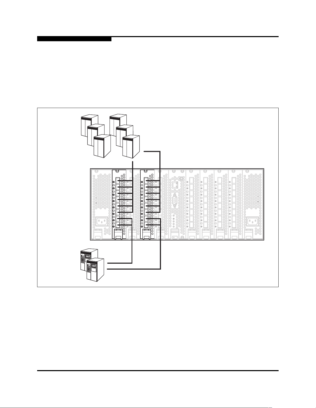
3.1.2
Redundancy and Latency
When planning a fabric, consider how to create redundant paths and minimize
latency. Initiators and targets experience the least amount of latency when
connected to the same I/O blade. For example, connecting initiator and target “A”
ports together on one I/O blade and initiato r and target “B” ports on another I/O
blade, as shown in Figure 3-1, creates redundant pa ths and minimizes latency.
Initiators
AB
AB
Targets
Figure 3-1. Single Switch Fabric with Initiators and Targets
3-2 59043-01 A
Initiators
3 – Planning
Devices
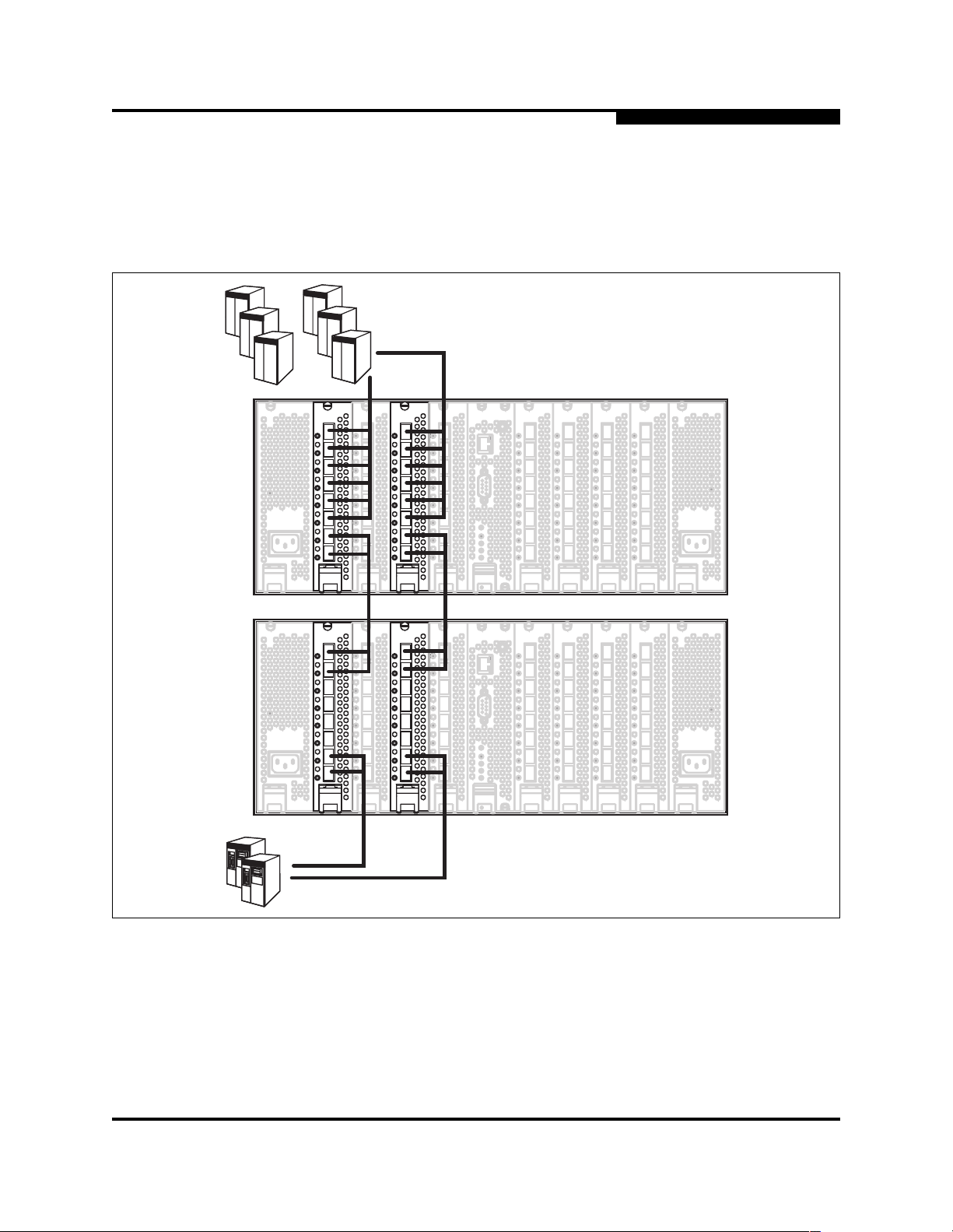
For a multiple switch fabrics in which initiators on one switch communicate with
targets on another, the same principles apply as shown in Figure 3-2. The “A” port
initiators and E_Ports are grouped together on one I/O blade with connections to
the corresponding “A” port targets and E_Ports on the same I/O blade on the
second switch. “B” port initiators, targets, and links are connected in a simi lar way.
AB
AB
Targets
Figure 3-2. Dual Switch Fabric with Initiators and Targets
59043-01 A 3-3

3 – Planning
Multiple Chassis Fabrics
3.2
Multiple Chassis Fabrics
By connecting switches together you c an expand t he number of availabl e ports for
devices. Each switch in the fabric is identi fied by a unique domain ID, and the
fabric will automatically resolve domain ID conflicts. Because the ports are selfconfiguring, you can connect SANbox2-64 and other FC-SW -2 compliant switches
together in a wide variety of topologies.
3.2.1
Domain ID, Principal Priority, and Domain ID Lock
The following switch configuration settings affect multiple chassis fabrics:
■ Domain ID
■ Principal priority
■ Domain ID lock
The domain ID is a unique number from 1– 239 that identifies each switch in a
fabric. The principal priority is a number (1 – 255) that determines the principal
switch which manages domain ID assignments for the fabric. The switch with the
highest principal pr io rity (1 i s high , 255 is l ow) beco mes the princ ipal switch. If the
principal priority is the same for all switches in a fabric, the switch with the lowest
WWN becomes the principal switch.
The domain ID lock allows (FALSE) or prevents (TRUE) the reassignment of the
domain ID on that switch. Switches come from the factory with the domain ID set
to 1, the domain ID lock set to FALSE, and the principal priority set to 254. Refer
to the SANbox2-64 Switch Management User’s Guide for information about
changing the domain ID using SANbox Manager. Refe r to ”Set Config Command ”
on page B-27 (Switch keyword) for information about changing the default do main
ID, domain ID lock, and principal priority parameters.
An unresolved domain ID conflict means that the switch wi th the higher WWN will
isolate as a separate fabric, and the Port Status LED status on both switches will
flash green to show the affected ports. If you connect a new switch to an existing
fabric with its domain ID unlocked, and a d omain ID conflict occurs, the new
switch will isolate a s a sep a rate f abric. However, you can remedy this by rese ttin g
the new switch or taking it offline then back online. The principal switch will
reassign the domain ID and the switch will join the fabric.
Note: Domain ID reassignment is not reflected in zoning that is defined by
domain ID/port number pair or Fibre Channel address. You must
reconfigure zones that are affected by domain ID reassignment. To
prevent zoning definitions fr om beco ming invalid, use the Set Config
Switch command to lock domain IDs. Refer to ”Set Config Command”
on page B-27.
3-4 59043-01 A

3.2.2
Common Topologies
The SANbox2-64 switch supports describes three commonly used fabric
topologies:
■ Cascade
■ Mesh
■ Multistage®
A cascade topology describes a fabric in which the switches are connected in a
linear fashion. If you connect the last switch back to the first switch, you create a
cascade-with-a-loop topology. The loop reduces latency because any switch can
route traffic in the shortest direction to any switch in the loop. The loop also
provides failover should a switch fail.
A mesh topology describes a fabric in which each chassis has at least one port
directly connected to every chassis in the fabric.
A Multistage topology descri bes a fabri c in which two or more edge switches
connect to one or more core switches. Each additional core switch increases the
bandwidth to each edge switch by 200 MB/s.
3 – Planning
Multiple Chassis Fabrics
59043-01 A 3-5

3 – Planning
Performance
3.3
Performance
The SANbox2-64 switch supports class 2 and class 3 Fibre Channel servi ce at
transmission rates of 1 Gbps or 2 Gbp s with a maximum frame size of 2148 byte s.
A port can transmit or receive at 1 Gbps or 2 Gbps depending on the device to
which it is connected. The port discovers the transmission speed prior to login
when the connected device powers up. Related performance characteristics
include the following:
■ Distance
■ Bandwidth
■ Latency
3.3.1
Distance
Consider the physical distribution of devices and switches in the fabric. Choose
SFP transceivers that are comp atible wit h the cable type, di stance, Fibre Channel
revision level, and the device host bus adapter. Refer to
Appendix A Specifications for more information about cable types and SFP
transceivers.
Each port is supported by a data buffer with a 12 credit capacity; that is, 12
maximum sized frames. For fibre optic cables, this enabl es full bandwidth over a
distance of 20 kilometers at 1 Gbps (0.6 credits/Km), or 10 kilometers at 2 Gbps
(1.2 credits/Km). Beyond this distance, however, there is some loss of efficiency
because the transmitting port must wait for an acknowledgement before sending
the next frame.
Longer distances can be spanned at ful l bandwi dth by extending credits on
G_Ports and F_Ports. Each port can donate up to 11 credits to a pool from which
a recipient port on the same I/O blade can borrow. For example, you can
configure a recipient port to borrow up to 66 credits from 6 ports for a total of 78
credits. This will support communication over approximately 130 Km at 1 Gbps
(78÷0.6) or 65 Km at 2 Gbps (78÷1.2).
You can configure recipient and donor ports using SANbox Manager or the Set
Config command. Refer to the ”Set Config Command” on page B-27 for more
information.
3-6 59043-01 A

3.3.2
Bandwidth
3 – Planning
Performance
Bandwidth is a measure of the volume of data that can be transmitted at a given
transmission rate. A port can transmit or receive at 1 Gbps or 2 Gbps depending
on the device to which it is connected. The switch supports all transmission rate
combinations as shown in Table 3-1.
Table 3-1. Port-to-Port Transmission Combinations
Source Port Rate Destination Port Rate Maximum Bandwdith
1 Gbps 1 Gbps 100 MB
1 Gbps 2 Gbps 100 MB
1 Gbps x 2 ports 2 Gbps 200 MB
2 Gbps 1 Gbps x 2 ports
2 Gbps 2 Gbps 200 MB
1
Bandwidth will be less for larger se quence sizes.
100 MB each port
1
3.3.3
Latency
In multiple chassis fabrics, each link between chassis contributes 100 or 200
megabytes of bandwidth between those chassis. When additional bandwidth is
needed between devices, increase the number of links between the connecting
switches. The switch guarantees in-or der-delivery with any number of links
between chassis.
Latency is a measure of how fast a frame travels from one port to another. The
factors that affect latency include transmission rate and the source/d estination
port relationship as shown in Table 3-2.
Table 3-2. Port-to-Port Latency
Source/Destination Rates Same I/O Blade
1 Gbps - 1 Gbps <1 µsec
2 Gbps - 2 Gbps <0.5 µsec
59043-01 A 3-7

3 – Planning
Device Access
3.4
Device Access
Consider device access need s within the f abric. Acc ess is controlled by t he use of
zones and zone sets. Some zoning strategies include the following:
■ Separate devices that use different operating systems.
■ Separate devices that have no need to communicate with other devices in
■ Separate devices into department, administrative, or other functional group.
■ Group TL_Port devices with targets and initiators to allow automatic
■ Reserve a path and its bandwidth from one port to another.
A zone is a named group of devices that can communicate with each other.
Membership in a zone can be defined by switch port number, port Fibre Channel
address, or by device worldwide name (WWN). Devices can communicate only
with devices that are members of the same zone. A zone can be a member of
more than one zone set. Several zone sets can be defined for a fabric, but only
one zone set can be active at one time. The active zone set determines the
current fabric zoning.
the fabric or have classified data.
discovery.
A zoning database is maintained on each switch consisting of all inactive zone
sets, the active zone set , all zones, alias es, and their member ship . The SANbox264 switch supports the following max imum limits:
■ 256 zone sets
■ 256 zones per zone set
■ 1000 total zones
■ 2000 members per zone
■ 256 aliases
■ 2000 members per alias
■ 2000 total number of alias and zone members
The following types of zones are supported:
■ Soft zone
■ Access Control List (ACL) - hard zone
■ Virtual Private Fabric (VPF) - hard zone
3-8 59043-01 A

3.4.1
Soft Zone
3 – Planning
Device Access
Soft zoning divides the fabric for purposes of controlling discovery. Members of
the same soft zone automatically discover and communicate freely with all other
members of the same zone. The soft zone boundary is not secure; traffic across
soft zones can occur if addressed correctly. The following rules apply to soft
zones:
■ Soft zones that include members from multiple switches need not include
the ports of the inter-switch links.
■ Soft zone boundaries yield to ACL and VPF zone boundaries.
■ Soft zones can overlap; that is, a port can be a member of more than one
soft zone.
■ Membership can be defined by Fibre Channel address, port ID and domain
ID, or worldwide name.
■ Soft zoning supports all port modes.
3.4.2
Access Control List Hard Zone
Access Control List (ACL) zoning divides the fabr ic for purposes of controlling
discovery and inbound traff ic. ACL zoning is a type of hard zoning that is
hardware enforced. This type of zoning is usef ul for controlling access to certain
devices without totally isolating them from the fabric. Members can communicate
with each other and transmit outside the ACL zone, but cannot receive inbound
traffic from out side the zone. The following rules apply to ACL zones:
■ The ACL zone boundary is secure against inbound traffic .
■ ACL zones can overlap; that is, a port can be a member of more than one
ACL zone.
■ ACL zones that include members from multiple switches need not include
the ports of the inter-switch links.
■ ACL zone boundaries supersede soft zone boundarie s, but yield to VPF
zone boundaries.
■ Membership can be defined only by domain ID and port ID.
■ ACL zoning supports all port modes except TL_Port.
59043-01 A 3-9

3 – Planning
Fabric Management
3.4.3
Virtual Private Fabric Hard Zones
Virtual Private Fabric (VPF) zoning divides the fabric for purposes of control ling
discovery and both inbound and outbound traffic. This type of zoning is useful for
providing security and reserving paths between devices to guarantee bandwidth.
VPF zoning is a type of h ard zoni ng that is ha rdwar e enforc ed. Members can only
transmit to and receive from members of the same VPF zone. The VPF zone
boundary is secure against bot h inbound and out bound tr af f ic. Th e f ollowi ng rule s
apply to VPF zones:
■ VPF zones that include members from multiple switches must include the
ports of the inter-sw itch links.
■ VPF zones cannot cross I/O blades.
■ VPF zones cannot overlap; that is, a port can be a member of only one VPF
zone.
■ VPF zone boundaries supersede both soft and ACL zone boundaries.
■ Membership can be defined only by domain ID and port ID.
■ VPF zoning supports all port modes.
3.5
Fabric Management
The SANbox Manager application and CLI execute on a management work station
that provides for the configuration, control, maintenance of the fabric. Supported
platforms include Windows, Windows NT, Solaris, and Linux. The SANbox
Manager application can manag e multipl e fabr ic s. Consi der how many fabr ics will
be managed, how many management workstations are needed, and whether the
fabrics will be managed with the CLI or SANbox Manager.
The switch supports a combined maximum of 15 logins. This includes SANbox
Manager inband and out-of-band logins, Appl icat ion Pr ogramming I nterfac e (API)
inband and out-of-band logins and Telnet logins. Of this 15, there can be a
combined maximum of 10 SANbox Manager and API logins. Additional logins will
be refused.
3-10 59043-01 A

3.6
Fabric Security
You manage fabric security on a switch basis through the creation of user
accounts. Each account consists of an account name, a password, and an
authority level. There are two authority levels: User and Admin. These authority
levels apply to SANbox Manager and to the CLI. User authority permits only
monitoring and display tasks. Admin authority permits all management tasks
including user administration. Consider your fabric security needs, who the
system administrators will be, and authority levels they should have.
■ Refer to ”Commands” on page B-3 for more information about authority
■ Refer to the ”User Command” on page B-70 for information about creating
■ Refer to the ”Set Setup Command” on page B-40 and the System keyword
3 – Planning
Fabric Security
levels.
user accounts.
for information about fabric security and the enforcement of user accounts.
59043-01 A 3-11

3 – Planning
Fabric Security
Notes
3-12 59043-01 A

Section 4
Installation
This section describes how to inst all and configur e the SANbox2-64 switch. It als o
describes how to load new firmware and how to recover a disabled switch.
4.1
Site Requirements
The following items are required for the installation of a SANbox2-64 switch:
■ Fabric management workstation
■ Power requirements
■ Environmental conditions
4.1.1
Fabric Management Workstation
The requirements for fabric management workstations running SANbox Manager
are described in Table 4-1:
Table 4-1. Management Workstation Requirements
Operating System
Memory 128 MB or more
Disk Space 150 MB per installation
Processor 300 MHz or faster
Hardware CD-ROM drive, RS-232 serial port, RJ-45 Ethernet port
Internet Browser Microsoft® Internet Explorer® or Netscape Navigator®
Telnet workstations require an RJ-45 Ethernet port or an RS-232 serial port and
an operating system with a Telnet client.
4.1.2
■ Windows® NT, 2000, 95/98
■ Linux® 6.2 Red Hat®
■ Solaris
Switch Power Requirements
Operating voltage requirements are as follows:
90 to 264 Vac; 47 to 63 Hz
59043-01 A 4-1
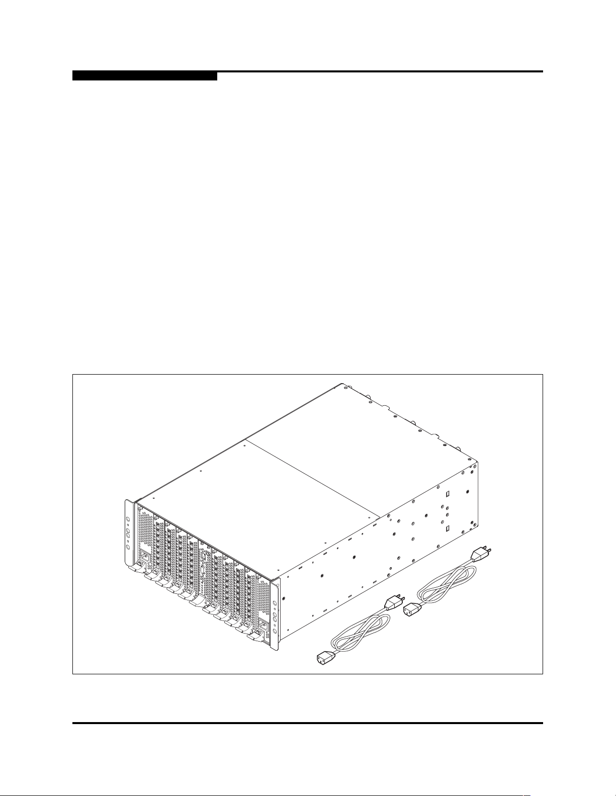
4 – Installation
Installing a Switch
4.1.3
Environmental Conditions
Consider the factors that af fect the climat e in your faci l ity suc h as equipment heat
dissipation and ventilation. The switch requires the following operating conditions:
■ Operating temperature range: 5° to 40° C (41°- 104°F)
■ Relative humidity: 15% - 80%, non-condensing
4.2
Installing a Switch
Unpack the switch and access ories. The SANbox2-64 produ ct i s shipped with the
components shown in Figure 4-1:
■ SANbox2-64 Fibre Channel Switch with firmware instal led
■ Power cords (2)
■ Rack mount brackets (2)
■ Rail kit (1)
■ CD containing the SANbox Manager switch management applicati on,
release notes, and documentation
Figure 4-1. SANbox2-64 Fibre Channel Switch
4-2 59043-01 A

Installing a SANbox2-64 switch involves the following steps:
1. Mount the switch.
2. Install SFP transceivers.
3. Connect the switch to the AC power source.
4. Connect the management workstation to the switch.
5. Install SANbox Manager.
6. Configure the switch.
7. Configure the ports.
8. Cable devices to the switch.
4.2.1
Mount the Switch
WARNING!! Two people are required to safely lift and install the SANbox2-64
4 – Installation
Installing a Switch
switch into a rack. To avoid personal injury or damage to the
switch, arrange for the help of an assistant.
When mounting products into a rack or cabinet, heavier products
should be placed near the bottom. A top heavy rack can become
unstable possibly resulting in equipment damage or personal
injury.
CAUTION!
If the switch is mounted in a closed or multi-unit rack assembly,
make sure that the operating temperature inside the rack
enclosure does not exceed the maximum rated ambient
temperature. Refer to ”Environmental” on page A -4.
The switch must rest on rails or a shelf in the rack or cabinet .
Allow 16 cm (6.5 in) minimum clearance at the front and rear of
the rack for service access and ventilation.
Do not restrict chassis air flow. Allow 16 cm (6.5 in) minimum
clearance at the front and rear of the rack for service access and
ventilation.
Multiple rack-mounted units connect ed to the AC supply circuit
may overload that circuit or overload the AC supply wiring.
Consider the power source capacity and the total power usage of
all switches on the circuit. Refer to ”Electrical” on page A-3.
Reliable grounding in the r ack must be maint ained from the s witch
chassis to the AC power source.
59043-01 A 4-3
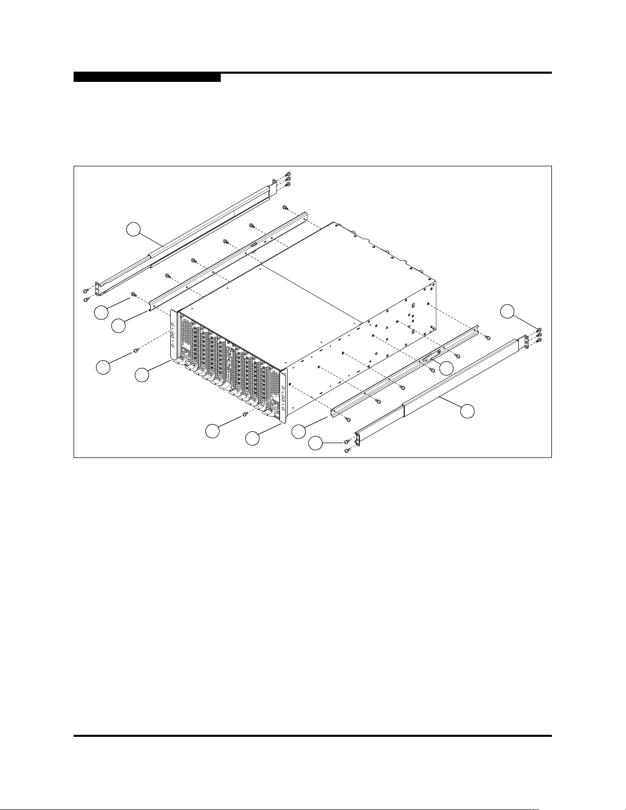
4 – Installation
Installing a Switch
6
The switch is designed to be mounted in a rack using the mounting brackets and
the SANbox2-64 rail kit shown i n Figure 4-2. To mount the switch in a rack, do the
following. Rack mounting instruct ions can also be found in the SANbox2-64 Rack
Mounting Guide packaged with the switch.
4
2
9
1
9
1
3
7
5
6
8
Figure 4-2. SANbox2-64 Rail Kit
1. You can install the switch in a rack “fans first” or “faceplate first”. The switch
comes with two bracket s (1 ) fastened to t he front of t he swit ch for a fans-f irst
installation. These instructions assume a fans-first installation. To install the
switch in the rack fac eplate f irst , remove th e mounti ng brac ket s and rei nst al l
them on the rear corners of the switch.
2. Install left (2) and right (3) switch rails on the switch using six 8-32 screws (4)
for each. Be sure that the latch i s cl osest t o the end of the sw itch t hat will be
installed first in the rack and that the latch tab (5) is pointing down.
3. Extend the rack rails (6) to fit the inner dimensions of the rack. The rail
flanges on both ends fit inside the rack. Be sure th at the inner rail is toward
the front. Fasten the front rail flange to the rack with two 10-32 screws (7)
using the upper and lower holes. Fasten the rear end of the rail to the rack
with three 10-32 screws (8).
4. Slide the switch and rail assembly into the rack rai ls. Fasten the switch to the
rack with two screws (9), one through each bracket.
4-4 59043-01 A

4.2.2
Install SFP Transceivers
The switch will support a variety of interconnection media. Refer to ”SFP
Transceivers” on p age 6-1 for information about removing and inst alling SFP
transceivers.
4.2.3
Connect the Switch to AC Power
WARNING!! This product is supplied with a 3-wire power cable and plug for
the user’s safety. Use this power cable in conjunction with a
properly grounded outlet to avoid electrical shock. An electrical
outlet that is not correctly wired could pla ce hazardous volt age on
metal parts of the switch chassis. It is the responsibility of the
customer to ensure that the outlet i s correctly wired and gr ounded
to prevent electrical shock.
You may require a different power cable in some countries
because the plug on the cable supplied with the equipment will
not fit your electrical outlet. In this case, you must supply your
own power cable. The cable you use must meet the following
requirements: For 125 Volt electrical service, the cable must be
rated at 13 Amps and be approved by UL and CSA. For 250 Volt
electrical service: The cable must be rated at 13 Amps, meet the
requirements of H05VV-F, and be approved by VDE, SEMKO,
and DEMKO.
4 – Installation
Installing a Switch
AVERTISSEMENT!!
Pour la sécurité de l’utilisateur, l’appareil est livré avec un câble
d’alimentation trifilaire et une fiche. Pour éviter toute secousse
électrique, enficher ce câble à une prise correctement mise à la
terre.Une prise électrique dont les fils sont mal branchés peut
créer une tension dangereuse dans les pièces métalli ques du
châssis switch. Pour éviter toute secousse électrique, s’assurer
que les fils sont correctement branchés et que la prise est bien
mise à la terre.
Dans certains pays les prises électriques sont de modèle
différent; on ne peut y enficher le câble de l’app areil. On doit donc
en utiliser un autre ayant les caractéristiques suivantes:
Alimentation 125 V: Câble pour courant nominal de 10 A, agréé
LAC et CSA. Alimentation 250 V: Câble pour courant nominal de
10 A, conforme au H05VV -F, et agréé VDE, SEMKO et DEMKO.
59043-01 A 4-5

4 – Installation
Installing a Switch
WARNUNG!!
Dieses Produkt wird mit einem 3-adrigen Netzkabel mit Stecker
geliefert. Dieses Kabel erfüllt die Sicherheitsanforderungen und
sollte an einer vorschriftsmäßigen Schukosteckdose
angeschlossen werden, um die Gefahr eines elektrische n
Schlages zu vermeiden.Elektrosteck dosen, die nicht richtig
verdrahtet sind, können gefährliche Hochspannung an den
Metallteilen des switch-Gehäuses verursachen. Der Kunde trägt
die V e rantwortung für eine vorsch riftsm äßige Verdrahtung und
Erdung der St eckdose zur Vermei dung eines elektrischen
Schlages.
In manchen Ländern ist eventuell die Verwendung eines anderen
Kabels erforderlich, da der Stecker des mitgelieferten Kabels
nicht in die landesüblichen Steckdosen paßt. In diesem Fall
müssen Sie sich ein Kabel besorgen, daß die folgenden
Anforderungen erfüllt: Für 125 V olt-Netze: 13 Ampere Kabel mit
UL- und CSA-Zulassung. Für 250 Volt-Netze: 13 Ampere Kabel
gemäß den Anforderungen der H05VV -F und VDE-, SEMKO- und
DEMKO-Zulassung.
To connect the switch to an AC power source and energize the switch, do the
following:
1. Connect the power cords to the AC power receptacles on the front of the
switch chassis.
2. Connect each power cord to a 3-wire, grounded, AC outlet that delivers
power in accordance with the power requirements in
Appendix A Specifications.
Note: To provide redundancy in the event of an AC power circuit failure,
connect the switch power supplies to separate AC circuits.
3. As the switch powers up, the chassis LEDs mark the process with the
following sequence:
a. All chassis LEDs illuminate briefly as the BIOS starts.
b. When the BIOS is complete, the Input Power LED remains illuminated
while the other LEDs are extinguished.
c. After about a minute, all LEDs illuminate a gain when t he switc h Power-
on Self Test (POST) completes. The POST tests the condition of
firmware, memories, data-paths, and switch logic circuitry.
4-6 59043-01 A

d. About 10 seconds later , the switch is operati onal: the I nput Power LED
remains illuminated, the Heartbeat LED flas hes steadily, and the two
remaining LEDs are extinguished. If the Heartbeat LED blinks steadily
about once per second, the POST was successful and you can
continue with the inst al lati on process. Any oth er bli nk pat tern i ndicate s
that an error has occurred. Refer t o ”Heartbeat LED Blink Pattern s” on
page 5-1 for more information about the error blink pattern.
4. Confirm that the Output Power LEDs on both power supplies are illu minated.
If not, check the power cords and the AC voltage source. Refer to ”Output
Power LED Is Extinguished” on page 5-1 1 for more information about
troubleshooting procedures.
4.2.4
Connect the Management Workstation to the Switch
Connect the management workstation to the switch in one of three ways:
■ Indirect Ethernet connection from the management workstation to t he switch
RJ-45 Ethernet connector through an Ethernet switch or a hub. This requires
a 10/100 Base-T straight cable as shown in Figure 4-3. With this method,
you can manage the switch with SANbox Manager or the CLI.
4 – Installation
Installing a Switch
■ Direct Ethernet connection from the management workstation to the switch
RJ-45 Ethernet connector. This requires a 10/100 Base-T cross-over cable
as shown in Figure 4-3. With this method, you can manage the switch with
the SANbox Manager application or the CLI.
■ Serial port connection from the management workstation to the switch RS-
232 connector. This requires a null modem F/F DB9 cable as shown in
Figure 4-3. With this method, you can manage the switch with the CLI.
Indirect Ethernet
RJ-45 Connection
81
8
7
6
5
4
3
2
1
Direct Ethernet
RJ-45 Connection
8
8
7
7
6
6
5
5
4
4
3
3
2
2
1
1
81
8
7
6
5
4
3
2
1
Serial RS -232
Connection
5
9
9
8
7
6
5
4
3
2
1
1
6
9
8
7
6
5
4
3
2
1
Figure 4-3. Ethernet and Serial Cable Connections
59043-01 A 4-7

4 – Installation
Installing a Switch
4.2.4.1
Ethernet Connection
To establish an Ethernet connection, do the following:
1. Connect a 10/100 Base-T cross-over cable from an RJ-45 port on the
management workstation directly to the RJ-45 Ethernet port; or a 10/100
Base-T straight cable indirect ly over an Ethernet network.
2. Open a command line window.
3. Open a Telnet session by entering the following command with the switch IP
address. The default IP address is 10.0.0.1
telnet 10.0.0.1
4. Log in to the switch. If fabric security i s d isabled, account names and
passwords are not enforced. Refer to the ”Set Setup Command” on page B-
40 for information about setting fabr ic security. The default account name
and password are (admin, password).
SANbox2 Login: admin
Password: ********
4.2.4.2
Serial Connection
To establish a serial port connection, do the following:
1. Connect a null modem F/F DB9 cabl e from a COM port on t he management
workstation to the RS-232 serial port on the switch.
2. Configure the connection according to your platform:
■ For Windows:
a. Open the HyperTerminal application on a Windows platform.
Choose the Start button, select Programs, Accessories,
HyperTerminal, and HyperTerminal.
b. Enter a name for the switch connection and choose an icon in the
Connection Description window. Choose the OK button.
c. Select the COM port in the Connect To window and choose the
OK button.
d. Enter the following COM Port settings in the COM Properties
window and choose the OK button.
❑ Bits per second: 9600
❑ Data Bits: 8
❑ Parity: Non e
❑ Stop Bits: 1
❑ Flow Control: None
4-8 59043-01 A

4 – Installation
Installing a Switch
■ For Linux:
a. Set up minicom to use the serial port. Create or modify the /etc/
minirc.dfl fil e with the follow in g co n tent:
pr portdev/ttyS0
pu minit
pu mreset
pu mhangup
b. Ver ify that all users have permissi on to run minicom. Review the /
etc/minicom/users file and confir m tha t the line "ALL" exists or
that there are specific user entri es.
c. Enter the following command at the Linux prompt:
minicom
■ For Solaris:
a. Set up Solaris to use t he seri al por t. Modif y the /et c/remot e fi le to
include the following lines:
sanbox2:\
:dv=/dev/term/a:br#9600:el=C^S^Q^U^D:ie%$:oe=^D:
b. Enter the following command at the Solaris prompt:
3. Log in to the switch. If fabric security i s d isabled, account names and
passwords are not enforced. Refer to the ”Set Setup Command” on page B-
40 for information about setting fabr ic security. The default account name
and password are (admin, password).
SANbox2 Login: admin
Password: ********
4.2.5
Installing SANbox Manager
You can install SANbox Manager on the Windows, Linux, and Solaris platforms.
Your switch was shipped with either a SANsurfer® Management Suite Disk or a
SANbox2 Installation Disk. Refer to the following installation instructions that
correspond to your situation:
■ SANsurfer Management Suite Disk - Windows Installation
■ SANsurfer Management Suite Disk - Linux Installation
■ SANsurfer Management Suite Disk - Solaris Installation
■ SANbox2 Installation Disk - Windows Installation
# tip sanbox2
■ SANbox2 Installation Disk - Linux Installation
■ SANbox2 Installation Disk - Solaris Installation
59043-01 A 4-9

4 – Installation
Installing a Switch
4.2.6
SANsurfer Management Suite Disk - Windows Installation
To install the SANbox Manager application on Windows from the SANsurfer®
Management Suite Disk, do the following:
1. Close all programs currently running, and Inser t the SANsurfer Management
Suite Disk into the management workstation CD-ROM drive. If the
SANsurfer Management Suite start page does not open in your default
browser, do the following:
a. Using Windows Explorer, double-click the drive letter which contains
the SANsurfer Management Suite Disk.
b. Locate and double-click the Start_Here.htm file to open the SANsurfer
Management Suite start page in your default browser.
2. On the SANsurfer Management Suite start page, choos e the SANbox
Switch Software button.
3. On the SANbox Switch Software page, scroll to the SANbox2 (2Gb) Series
area.
4. In the Windows column, choose the SANbox Manager link to open the File
Download window .
5. You have a choice of running the installation file from the CD-ROM or
downloading the installati on file to your hard drive. Choose one of the
following:
■ Open the installation file from the CD-ROM and follow the SANbox
Manager installation instructions.
■ Specify a location in which to save the
sansurfer_windows_install.exe file, and choose the Save button.
Double-click the saved sansurfer_windows_install.exe file and
follow the SANbox Manager installat ion instructions.
4-10 59043-01 A

4.2.7
SANsurfer Management Suite Disk - Linux Installation
To install the SANbox Manager application on Linux from the SANsurfer
Management Suite Disk, do the following:
1. Close all programs currently running, and i nsert the SANsurfer Management
Suite Disk into the management workst ation CD-ROM driv e. If a f ile browser
window opens showing icons for the contents of the CD-ROM, double-click
the Start_Here.htm file to open the SANsurfer Management Suite start
page. If a file browser does not open, double-cl ick the CD-ROM icon on the
to open the browser. If there is no CD-ROM icon, do the following:
a. Open an xterm or other terminal window.
b. Mount the CD-ROM. From a shell prompt, enter the following
command:
mount /mnt/cdrom
c. Execute your web browser to view the Start_Here.htm document
using one of the following commands:
4 – Installation
Installing a Switch
$mozilla file:/mnt/cdrom/Start_Here.htm
or
$netscape file:/mnt/cdrom/Start_Here.htm
d. The SANsurfer Management Suite start page opens in your default
browser.
2. On the SANsurfer Management Suite start page, choos e the SANbox
Switch Software button.
3. On the SANbox Switch Software page, scroll to the SANbox2 (2Gb) Series
area.
4. In the Linux column, choose the SANbox Manager link to open the Save As
window.
5. Enter a path name to save the sansurfer_linux_install.bin file, and choose
the Save button.
6. Open a terminal window for the directory in which the
sansurfer_linux_install.bin file was saved, and enter the following
command and press the Enter key:
chmod +x sansurfer_linux_install.bin
7. Enter the following command:
./sansurfer_linux_install.bin
8. Press the Enter key, and follow the SANbox Manager installation
instructions.
59043-01 A 4-11

4 – Installation
Installing a Switch
4.2.8
SANsurfer Management Suite Disk - Solaris Installation
To install the SANbox Manager application on Solaris from the SANsurfer
Management Suite CD-ROM, do the following:
1. Close all programs currently running, and i nsert the SANsurfer Management
Suite Disk into the management workstation CD-ROM drive. If the
SANsurfer Management Suite start page does not open in your default
browser, do the following:
a. Right-click the to open the Works hops Menu.
b. Point to and select Files, then select Fil e Manag er.
c. In File Manager, double-click t he CD-ROM icon, and then double-click
the Sansur fe r fo l de r.
d. In the Sansurfer folder, double-click the Start_Here.htm file to open
the SANsurfer Management Suite start p age in your default browser.
2. On the SANsurfer Management Suite start page, choos e the SANbox
Switch Software button.
3. On the SANbox Switch Software page, scroll to the SANbox2 (2Gb) Series
area.
4. In the Solaris column, choose the SANbox Manager link to open the Save
As window .
5. Enter a path name to save the sansurfer_solaris_install.pkg file and
choose the Save button.
6. Open a terminal window for the directory in which the
sansurfer_solaris_install.pkg file was saved, and enter the following
command:
chmod +x sansurfer_solaris_install.pkg
7. Press the Enter key.
8. Enter the following command:
./sansurfer_solaris_install.pkg
9. Press the Enter key, and follow the SANbox Manager installation
instructions.
Note: If you download SANbox Manager from a server, be sure the
downloaded file has execute permission before installing.
4-12 59043-01 A

4.2.9
SANbox2 Installation Disk - Windows Installation
To install the SANbox Manager application on Windows from the SANbox2
Installation Disk, do the following:
1. Close all programs currently running, and insert the SANbox2 Installation
Disk into the management workstation CD-ROM drive.
2. Using Windows Explorer, double-click the drive letter which contains the
SANbox2 Installation Disk.
3. Double click the SANbox_Manager folder, then double click the Windows
folder.
4. Double click the executable f il e and follow the SANbox Manager installation
instructions.
4.2.10
SANbox2 Installation Disk - Linux Installation
To install the SANbox Manager applicatio n on Linux f rom the SANbo x2 Install ation
Disk, do the following:
4 – Installation
Installing a Switch
1. Close all programs currently running, and insert the SANbox2 Installation
Disk into the management workstation CD-ROM drive.
2. Open the File Manager and double-click on the CD-ROM icon.
3. Double click the SANbox_Manager folder, then double click the Linux folder.
4. Double click the executable f il e and follow the SANbox Manager installation
instructions.
4.2.11
SANbox2 Installation Disk - Solaris Installation
To install the SANbox Manager application on Solaris from the SANbox2
Installation Disk, do the following:
1. Close all programs currently running, and insert the SANbox2 Installation
Disk into the management workstation CD-ROM drive.
2. Open a terminal window. If the disk isn’t already mounted, enter the
following command:
mount /mnt/cdrom
3. Move the directory on the disk that contains the executable. Enter the
following command:
cd cdrom/cdrom0/sanbox~1/solaris
4. Run the executable and fol low the SANbox Manager inst allation inst ructions.
Enter the following command:
pkgadd -d sol_pkg
59043-01 A 4-13

4 – Installation
Installing a Switch
4.2.12
Configure the Switch
Do the following to configure a switch using the SANbox Manager application.
Refer to the SANbox2-64 Switch Management User’s Guide for more information
about configuring a swit ch. You can also confi gure t he switch us ing t he CLI. Ref er
to Appendix B Command Line Interface for more information.
1. Connect to the switch using an Ethernet connection and run SANbox
Manager.
2. Open the Fabric menu and select Add Fabric to open the Add a New Fabric
window.
3. Enter a fabric name and the IP address of the switch through which to
manage the fabric. The defa ult IP addr ess is 10.0. 0.1. If t his is a n ew switch,
leave the login name and password fields empty, and choose the Add
Fabric button. By default, fabric security is disabled, and therefore account
names and passwords are not enforced. Refer to the ”Set Setup Command”
on page B-40 for information about setting fabric security.
4. Open the Switch menu and select Switch Properties. In the Switch
Properties window , ent er a chassis name. Accept the def ault domain ID, and
choose the OK button.
4-14 59043-01 A

5. Open the Switch menu and select Network Properties. In the Network
Properties window, enter values for the IP address, subnet mask, and
gateway address. Accept the default boot method. If you know the SNMP
configuration settings, enter those as well. Choose the OK button.
6. Set the date and time. Double click on the switch in the topology displ a y. In
the faceplate display, open the Switch menu and select Set Date/Time .
Enter the date and time in the Switch Date a nd Ti me window and choose the
OK button. Reset the switch when prompt ed to i mpl ement the new and dat e
and time.
Repeat this process for each switch in the fabri c, then connect the switches.
4.2.13
Configure the Ports
Configuring a port involves defining the port mode. For public devices and other
switches, a switch automatically sets the port mode as each port discovers the
type of device to which it is connected.
A GL_Port will self configure as an FL_Port when connected to a loop of public
devices or an F_Port when connected to a single device. A G_Port will self
configure as an F_Port when connected to a single public device. Both GL_Ports
and G_Ports self configure as E_Ports when connected to another switch. The
default port mode is GL_Port. Refer to the SANbox2-64 Switch Management
User’s Guide for more information about conf iguring por ts. You can also configure
ports using the CLI. Refer to Appendix B Command Line Interface for information
about the command line interface.
4 – Installation
Installing a Switch
4.2.14
Cable Devices to the Switch
Connect cables to the SFP transceivers and their corresponding devices, and
then energize the devices. Device host bus adapters can ha ve SFP (or SFF)
transceivers or GigaBit Interface Converters (GBIC). LC-type duplex fiber optic
cable connectors are designed for SFP transcei vers, while SC-type connectors
are designed for GBICs. Duplex cable connectors are keyed to ensure proper
orientation. Choose the fiber optic cable with the connector combination that
matches the device host bus adapter.
59043-01 A 4-15

4 – Installation
Install Firmware
4.3
Install Firmware
The switch comes with current firmware inst alled. You can upgrade the firmware
from the management workstation as new fir mware become s availabl e. Fir mware
installation i nvolve s loading the fir mware image file ont o the switch, un packi ng the
image file, and then resetting the switch to activate the new firmware. New
firmware can be loaded on the switch while the switch is operat ing without
disrupting service. However, you must reset the switch to activate the new
firmware, which does disrupt servic e.
You can use the SANbox Manager application or the CLI to install new firmware:
■ The SANbox Manager application loads and unpacks the firmware image
■ When using the CLI on a workstation that has an FTP server, you can open
file in one operation. Refer to ”Using SANbox Manager to Install Firmware”
on page 4-16.
a Telnet session and load and unpack the firmware image file using the CLI
Image command. Refer to ”Using the CLI to Install Firmware” on page 4-17.
■ When using the CLI on a workstation without an FTP ser ver, you must open
an FTP session through the switch to load the image file, then open a Telnet
session to unpack it with the CLI Image command. Refer to ”Using FTP and
the CLI to Install Firmware” on page 4-18.
4.3.1
Using SANbox Manager to Install Firmware
To install firmware using SANbox Manager, do the following:
1. From the Faceplate display, open the Switch menu and select Load
Firmware.
2. In the Firmware Upload window, browse and select the firmware file you
want to load.
3. In the Firmware Upload window, choose the Start button to begin the
loading process. When the firmware is finished loading, the Bytes
Transfer red f ield displays the number of bytes that have been transferred.
4. Choose the Close button to close the Firmware Upload window.
5. Open the Switch menu and select Reset Switch to activate the new
firmware.
4-16 59043-01 A

4.3.2
Using the CLI to Install Firmware
To install firmware using the CLI when an FTP server is present on the
management workstation, do the following:
1. Connect to the switch through the Ethernet or the serial port and open a
Telnet session.
2. Enter the following account name and password:
SANbox2 Login:admin
Password: password
3. To start an admin session, enter the following:
cli $> admin start
4. Retrieve the firmware file. The device on which th e firm ware file is stored
must be running an FTP ser ver. Enter the following command to retrieve th e
firmware file from the specified IP address:
cli (admin) #> image fetch username 10.0.0.254
firmwarefilenametoload firmwarefilenameonswitch
Connected to 10.0.0.254.
4 – Installation
Install Firmware
Note: If prompted for your password, enter your password (for that IP
Address) and press the Enter key.
331 Password required for username.
Password:
230 User username logged in.
bin
200 Type set to I.
verbose
Verbose mode off.
5. Enter the following command to display the list of firmware files:
cli (admin) #> image listfirmwarefilenameonswitch
6. Enter the following command to install the new firmware:
cli (admin) #>image unpack firmwarefilenameonswitch
7. Reset the switch to activate the new firmware.
cli (admin) $>reset
59043-01 A 4-17

4 – Installation
Install Firmware
4.3.3
Using FTP and the CLI to Install Firmwa re
To install firmware using the CLI when the management workstation does not
have an FTP server, do the following:
1. Connect to the switch through the Ethernet or the serial port.
2. Move to the folder or directory that contains the new firmware image file.
3. Establish communications with the switch using the File Transfer Protocol
(FTP). Enter one of the following on the command line:
>ftp xxx.xxx.xxx.xxx
or
>ftp switchname
where xxx.xxx.xxx.xxx is the switch IP address, and switchname is the
switch name associated with the IP address.
4. Enter the following account name and password:
user:images
password: images
5. Activate binary mode and copy the firmware image file on the switch:
ftp>bin
ftp>put filename
6. Close the FTP session.
ftp>quit
7. Establish communications with the swi tch usi ng the CLI. Enter one of the
following on the command line:
telnet xxx.xxx.xxx.xxx
or
telnet switchname
where xxx.xxx.xxx.xxx is the switch IP address, and switchname is the
switch name associated with the IP address.
8. A Telnet window opens prompting you for a login. Enter an account name
and password. The default account name and p assword are (admin,
password).
9. Open an Admin session to acquire the necessary authority.
cli $>admin start
4-18 59043-01 A

10. Display the list of firmware image files on the switch to confirm that the file
was loaded. Refer to the ”Image Command” on page B-15 for more
information.
cli (admin) $>image list
11. Unpack the firmware image file to install the new firmware in flash memory.
cli (admin) $>image unpack filename
12. Reset the switch to activate the new firmware. This will close the Telnet
session by default.
cli (admin) $>reset
4.4
Powering Down a Switch
Simply unplugging the switch from the power source does not allow the switch to
complete executing tasks and could lead to flash memory corruption. For this
reason, open a Telnet session and use the Shutdown command to initiate an
orderly shut down, then power down the switch. Refer to the ”Shutdown
Command” on page B-65.
4 – Installation
Powering Down a Switch
59043-01 A 4-19

4 – Installation
Powering Down a Switch
Notes
4-20 59043-01 A

Diagnostic information about t he switch is avail able through the c hassis LEDs, the
power supply LEDs, and the Port Status LED. Diagnostic information is also
available through the SANbox Manager and CLI event logs and error displays.
This section describes two types of diagnostics: Power On Self Test (POST) and
chassis. POST diagnostics describe the Heartbeat LED and the Port Status LED
indications. Chassis diagnostics cover power supply and fan diagnostics as well
as over temperature conditions. This secti on also describes how to use
maintenance mode to recover a disabled switch.
5.1
POST Diagnostics
The switch performs a series of Power On Self Tests (POST) as part of its powerup procedure. The POST diagnostic program performs the following t ests:
■ Checksum tests on the boot firmware in PROM and the switch firmware in
flash memory
■ Internal data loopback test on all ports
Section 5
Diagnostics/Troubleshooting
■ Access and integrity test on the ASIC
During the POST, the switch logs any errors encoun ter ed. Some POST error s ar e
fatal, others are n on-fat al. The s witch use s the Heart beat LED and the Port S t at us
LED to indicate switch and port status. A fatal error disables the switch so that it
will not operate. A non-fatal error allows the switch to operate, but disabl es the
ports that have errors. Whether the problem is fatal or non-fatal, contact your
authorized maintenance provider.
If there are no errors, the Heartbeat LED blin ks at a steady rate of once per
second. If a fatal erro r occurs, the Heartbeat LED will show an error blink pattern.
If there are non-fatal err ors, the switch disables the failed ports and flashes the
associated Port Status LEDs. Refer to ”Heartbeat LED Blink Patterns” on page 5-
1 for more information about Heartbeat LED blink p a tterns.
5.1.1
Heartbeat LED Blink Patterns
5.1.1.1
Normal (all pass)
If all POST diagnostics pass, the switch will go to normal operation and the
Heartbeat LED will blink at a steady rate of one (1) blink pe r second.
59043-01 A 5-1

5 – Diagnostics/Troubleshooting
POST Diagnostics
5.1.1.2
Maintenance Mode Pattern
Steady illumination indicates that the switch is in maintenance mode, which
returns the switch IP address to 10.0.0.1. From maintenance mode, you may
reload firmware, reset the password to the factory default, and remove a corrupt
configuration.
5.1.1.3
Internal Firmware Failure Blink Pattern
An internal firmware failure bl ink pattern is 2 blinks per second followed by a two
second pause. The 2-blink error p attern indi cates that the fir mware has failed, and
that the switch must be reset. Press and release the Maintenance button to reset
the switch.
1 second
5.1.1.4
2 seconds
Fatal Er ror Blink Pattern
A fatal error blink pattern is 3 blinks per second followed by a two second paus e.
The 3-blink error pattern i ndicates that a fatal error has lef t the switch inoperable.
If a fatal error occurs, contact your authorized maintenance provider.
1 second
5.1.1.5
2 seconds
Configuration File System Error Blink Pattern
A configuration file system error blink pattern is 4 blinks per second foll owed by a
two second pause. The 4-blink error pattern indicates that a configurati on file
system error has occurred, and that the configuration file must be recreated.
1 second
2 seconds
To recreate the configuration file, do the following:
1. Open a Telnet session and use the Shutdown command to close activity on
the switch, then power down the switch. Refer to the ”Shut down Command”
on page B-65.
5-2 59043-01 A

5 – Diagnostics/Troubleshooting
POST Diagnostics
2. Place the switch in maintenance mode. Press and hold the Maintenance
button for about 4 seconds. Refer to ”Recovering a Switch ” on p age 5-12 for
more information about placing the switch in maintenance mode.
3. Establish a Telnet session with the switch using the default IP address
10.0.0.1.
telnet 10.0.0.1
4. Enter the account name (prom) and password (prom), and press the Enter
key.
Sanbox2 login: prom
Password:xxxx
[username@host:Itasca]% telnet 10.0.0.1
Trying 10.0.0.1...
Connected to 10.0.0.1.
Escape character is ’^]’.
5. The following menu is displayed. Enter "6" (Remake Filesystem) and press
the Enter key to recreate the configuration file.
0) Exit
1) Image Unpack
2) Reset Network Config
3) Reset Password File
4) Copy Log Files
5) Remove Switch Config
6) Remake Filesystem
7) Reset Switch
Option: 6
6. When the recreate process is complete, select opti on 7 to reset the switch
and exit maintenance mode.
7. If a previously saved configuration fi le is available for the switch, do the
following to restore the configuration file.
a. Establish communications with the switch using the File Transfer
Protocol (FTP). Enter one of the followi ng on the command lin e:
>ftp xxx.xxx.xxx.xxx
or
>ftp switchname
where xxx.xxx.xxx.xxx is the switch IP address and switchname is the
switch name associated with the IP address.
b. Enter the following account name and password:
user:images
password:images
59043-01 A 5-3

5 – Diagnostics/Troubleshooting
POST Diagnostics
c. Activate binary mode and copy the configuration file from the
workstation to the switch. The configuration file must be named
"configdata".
ftp>bin
ftp>put configdata
d. Close the FTP session.
ftp>quit
e. Establish communications with the switch using Telnet. Enter one of
the following on the command line:
telnet xxx.xxx.xxx.xxx
or
telnet switchname
where xxx.xxx.xxx.xxx is the switch IP address and switchname is the
switch name associated with the IP address.
f. A Telnet window opens prompting you for a login. Enter an account
name and password. The default account name and password are
(admin, password).
g. Open an admin session to acquire the necessary authority.
cli $>admin start
h. Restore the configuration file.
cli (admin) $>config restore
i. Reset the switch and close the Telnet session.
cli (admin) $>reset
5-4 59043-01 A
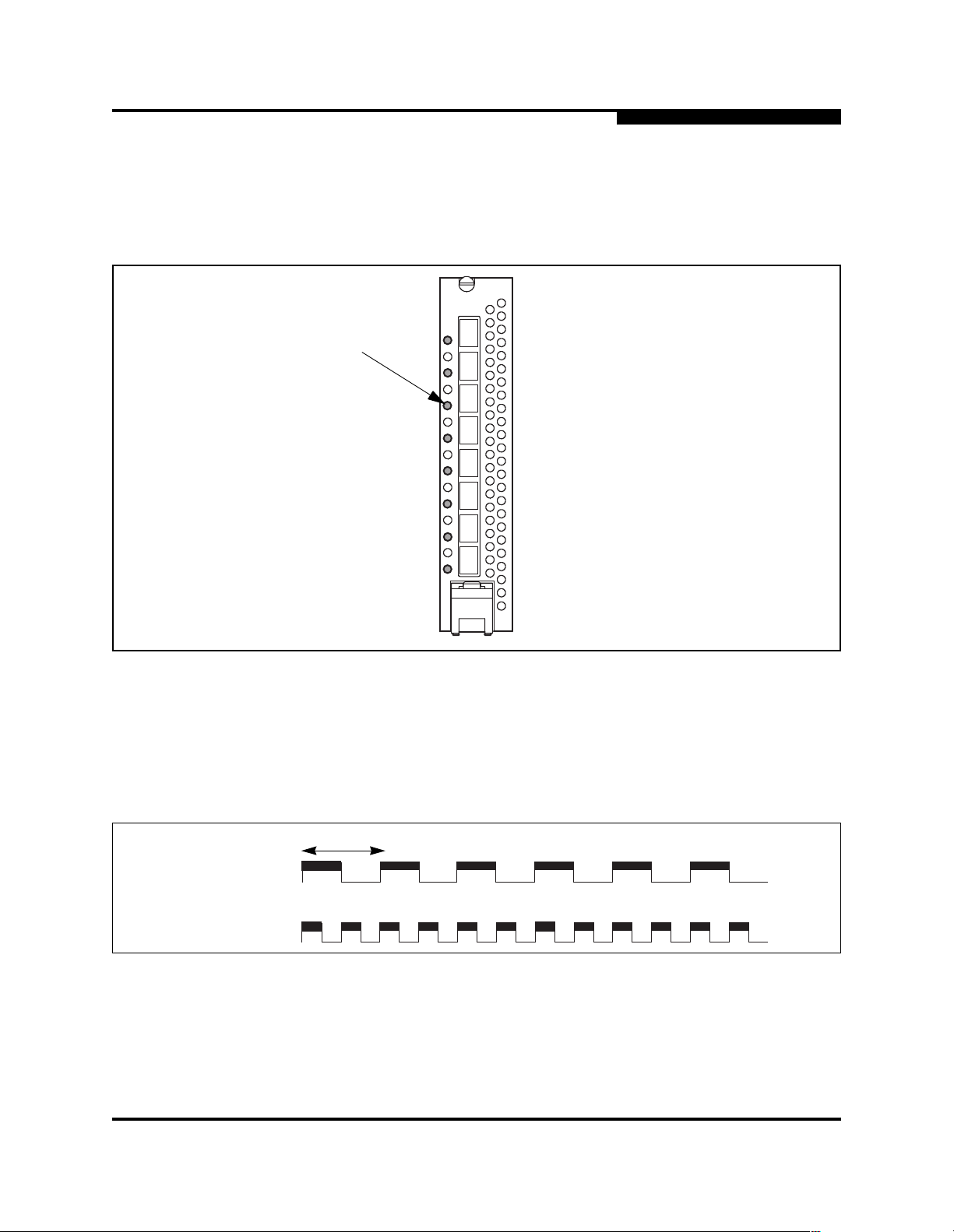
5.1.2
Port Status LED Indications
Port diagnostics for each port are indicated by the Port Status LED as shown in
Figure 5-1.
Port Status
LED
5 – Diagnostics/Troubleshooting
POST Diagnostics
Figure 5-1. Port Status LED
The Port Status LED has three indications:
■ Logged in - Continuous illumination.
■ Logging in - Flashes at roughly once per second as shown in Figure 5-2.
■ Error - Flashes at roughly twice per second as shown in Figure 5-2.
1 second
Logging In
Error
Figure 5-2. Port Status LED Indications
59043-01 A 5-5

5 – Diagnostics/Troubleshooting
POST Diagnostics
If a Port Status LED shows an error indication, review the alarm log for messages
regarding the affected port. You can inspect the alarm log using the Alarm data
tab in SANbox Manager faceplate display or the Show Alarm command. Pertin ent
alarm log messages will point to one or more of the following conditions:
■ E_Port isolation
■ Excessive port errors
5.1.2.1
E_Port Isolation
A Port Status LED error indication is often the result of E_Port isolation. An
isolated E_Port is indicated by a re d link in the SANbox Manager t opology display.
E_Port isolation can be caused by conflicting domain IDs, conflicting timeout
values, or conflicting zone membership between active zone sets. Refer to the
SANbox2-64 Switch Management User’s Guide for information about how to
change domain IDs, timeout values, and edit zoning.
Review the alarm log and do the following to diagnose and corr ect an isolated
E_Port:
1. Display the fabric domain IDs using the Show Domains command or the
Switch data tab in the SANbox Manager topology di splay. Are all domain IDs
in the fabric unique?
■ Yes - Continue.
■ No - Correct the domain IDs on the offending switches using the Set
Config Switch command or the SANbox Manager Switch Properties
window. Reset the port. If the condition remains, continue.
2. Compare the RA_TOV, ED_TOV, RT_TOV timeout values for all switches in
the fabric using the Show Config Switch command or the Switch data tab of
the SANbox Manager topology display. Is each timeout value the same on
every switch?
■ Yes - Continue.
■ No - Correct the timeout values on the offending switches using the
Set Config Switch command or the SANbox Manager Switch
Properties window. Reset the port. If the condition remains, continue.
5-6 59043-01 A

3. Display the active zone set on each switch using the Zoning Active
command or the Active Zoneset tab of the SANbox Manager topology
display. Compare the zone membership between the two active zone sets.
Are they the same?
■ Yes - Contact your authorized maintenance provider.
■ No - Deactivate one of the active zone sets or edit the conflict ing zones
so that their membership is the same. Reset the port. If the condition
remains, contact your authorized maintenance provider.
Note: This can be caused by merging two fabrics whose active
5.1.2.2
Excessive Port Errors
The switch monitors a set of port errors and generates alarms based on userdefined sample intervals and thresholds. Refer to the SANbox2-64 Switch
Management User’s Guide for information about managing alarms. These port
errors include the following:
5 – Diagnostics/Troubleshooting
POST Diagnostics
zone sets have two zones with the same name, but
different membership.
■ CRC errors
■ Decode errors
■ ISL connection count
■ Login errors
■ Logout errors
■ Loss-of-signal error s
If the count for any of these errors exceeds the rising threshold for three
consecutive sample intervals, the switch generates an alarm and disables the
affected port, changing its operational state to “down”. Port errors can be caused
by the following:
■ Thresholds are too low or the sample interval is too small
■ Faulty Fibre Channel port cable
■ Faulty SFP
■ Faulty port
■ Fault device or HBA
Review the alarm log to determine if excessive port errors are responsible for
disabling the port. Look for a message that mentions one of the monitored error
types indicating that the port has been dis abled, then do the following:
59043-01 A 5-7

5 – Diagnostics/Troubleshooting
POST Diagnostics
1. Examine the alarm configuration for the asso ciated error using the Show
Config Threshold command or the SANbox Manager application. Refer to
the ”Show Config Command” on page B-55. Refer to Table B-4 for a list of
the alarm configuration defaults. Are the thresholds and sample interval
correct?
■ Yes - Continue
■ No - Correct the alarm configuration. If the condi tion remains, continue .
2. Reset the port, then perform an external port loopback test to validate the
port and the SFP. Refer to the ”Test Command” on page B-66 or the
SANbox2-64 Switch Management User’s Guide for informatio n about testing
ports. Does the port pas s the test?
■ Yes - Continue
■ No - Replace the SFP and repeat the test. If the port does not p ass the
test, contact your authorized maintenance provider. Otherwise
continue.
3. Replace the Fibre Channel port cable. Is the problem corrected?
■ Yes - C o mp le te .
■ No - Continue.
4. Inspect the device to which the affected port is connected and confirm that
the device and its HBA are working properly. Make repairs and corrections
as needed. If the condition remains, contact your authorized maintenance
provider.
5-8 59043-01 A

5.2
Chassis Diagnostics
Chassis diagnostics are indicate d by the chassi s and power supply LEDs as
shown in Figure 5-3.
Input Power LED
(Green)
5 – Diagnostics/Troubleshooting
Chassis Diagnostics
Output Power LED
(Green)
Power Suppl y Fault
LED (Amber)
Fan Fail LED
(Amber)
Over Temperature
LED (Amber)
The following conditions are described:
■ Over Temperature LED is illuminated
■ Input Power LED is extinguished
■ Fan Fail LED is illuminated
■ Output Power LED is extinguished
■ Power Supply Fault LED is illuminated
Figure 5-3. Chassis and Power Supply LEDs
59043-01 A 5-9

5 – Diagnostics/Troubleshooting
Chassis Diagnostics
5.2.1
Over Temperature LED is Illuminated
The Over Temperature LED illuminates to indicate that the switch logic c ir cuitry is
overheating. If the Over Temperature LED illuminates, do the following:
1. Inspect the chassis fans. Are the intake openings clear? Are all fans
operating and producing air flow?
■ Yes - Continue.
■ No - Remove any debris from fan intakes and exhausts if necessary.
Replace any fan that is not operating. Refer to Section 6 Removal/
Replacement. If the condition remains, continue.
2. Consider the ambient air temperature near the switch. Ma ke ne cessary
corrections. If the condition remains, shut down the switch immediately and
contact your authorized maintenance provider.
5.2.2
Input Power LED Is Extinguished
The Input Power LED illuminates to indicate that the switch logic circuitry is
receiving proper voltages . If the Input Power LED is extinguished, inspect the
Output Power LED. Is the Output Power LED illuminated?
■ Yes - Contact your authorized maintenance provider.
■ No - Refer to ”Output Power LED Is Extinguished” on page 5-11.
5.2.3
Fan Fail LED is Illuminated
The Fan Fail LED illuminates to indicate a malfunction with one or more of the
chassis fans. If the Fan Fail LED illuminates, do the following:
1. Inspect the chassis fan connections. Remove and reinstall the chassis fan.
Refer to Section 6 Removal/Replacement. If the condition remains,
continue.
2. Are all fans operating and producing equal air flow?
■ Yes - Contact your authorized maintenance provider.
■ No - Replace the weaker chassis fan. Refer to Section 6 Removal/
Replacement. If the condition remains, contact your authorized
maintenance provider.
Note: Removing a fan will not illuminate the Fan Fail LED.
5-10 59043-01 A

5.2.4
Output Power LED Is Extinguished
The Output Power LED illuminates to indicate that the power supply is produci ng
the proper voltages. If the Output Power LED is extinguished, do the following:
1. Inspect the Power Supply Fault LED. Is the Power Supply Fault LED
illuminated?
■ Yes - R e fe r to ”Power Supply Fault LED is Illuminated” on page 5-11.
■ No - Continue.
2. Inspect the power cables and connectors. Are the cables unplugged? Are
the cables or connectors damaged?
■ Yes - Make necessary corrections or repairs. If the condition remains,
continue.
■ No - Continue.
3. Inspect the power source. Is the power source deli vering the pr oper volt age?
5 – Diagnostics/Troubleshooting
Chassis Diagnostics
■ Yes - Continue
■ No - Make necessary repairs. If the condition remains, continue.
4. Replace the power supply. Refer to Section 6 Removal/Replacement. If the
condition remains, contact your authorized maintenance provider.
5.2.5
Power Supply Fault LED is Illuminated
The Power Supply Fault LED illuminates to ind icate a power supply fau lt. Possible
fault conditions include high temperature, high output voltage, or low output
voltage. If the Power Supply Fault LED illuminates, do the following:
1. Inspect the chassis fans. Are the intake openings clear? Are all fans
operating and producing air flow?
■ Yes - Continue.
■ No - Remove any debris from fan intakes if necessary. Replace any
fan that is not operating. Refer to Section 6 Removal/Replacement. If
the condition remains, continue.
2. Consider the ambient air temperat ure near the swi tch and c lea rance aro und
the switch. Make necessary corrections. If the condition remains, continue.
3. Replace the power supply. Refer to Section 6 Removal/Replacement. If the
condition remains, contact your authorized maintenance provider.
59043-01 A 5-11

5 – Diagnostics/Troubleshooting
Recovering a Switch
5.3
Recovering a Switch
A switch can become inoperable or unavailable for the following reasons:
■ Firmware becomes corrupt
■ IP address is lost
■ Switch configuration becomes corrupt
■ Forgotten password
In these specific cases, you can recover the switch using maintenance mode.
Maintenance mode returns the switch IP address to 10.0.0.1 and provides
opportunities to do the following:
■ Unpack a firmware image file
■ Restore the network configuration parameters to the default values
■ Remove all user accounts and restore the Admin account name pas sword to
the default.
■ Copy the log file
■ Restore factory defaults for all but user accounts and zoning
■ Restore all switch configuration par a meters to the factory default values
■ Reset the switch
To recover a switch, do the following:
1. Place the switch in maintenance mode. Do the following:
a. Power down the switch.
b. Press and hold the Maintenance button with a pointed tool, then power
up the switch. All chassis LEDs will illuminat e, then extinguish leaving
only the Input Power LED illuminated. Release the button.
2. Allow one minute for the switch to complete its tests. When the switch is in
maintenance mode, the Input LED will be illuminated and the Heartbeat LED
will illuminate continuously. All other chassis LEDs will be extinguished.
3. Establish a Telnet session with the switch using the maintenanc e mode IP
address 10.0.0.1.
4. Enter the maintenance mode account name and password (prom, prom),
and press the Enter key.
Sanbox login: prom
Password:xxxx
[username@anteater:Itasca]% telnet 10.0.0.1
Trying 10.0.0.1...
Connected to 10.0.0.1.
Escape character is ’^]’.
5-12 59043-01 A

5. The maintenance menu displays several recovery options. To select a
switch recovery option, press the corr esponding number (displayed in
option: field) on the keyboard and press the Enter key.
These options and their use are described in the following sections.
5.3.1
Maintenance – Exit
This option closes the current login session. To log in again, enter the
maintenance mode account name and password (prom, prom).
5 – Diagnostics/Troubleshooting
Recovering a Switch
0) Exit
1) Image Unpack
2) Reset Network Config
3) Reset Password File
4) Copy Log Files
5) Remove Switch Config
6) Remake Filesystem
7) Reset Switch
Option:
5.3.2
Maintenance – Image Unpack
This option unpacks and installs new firmware when the current firmware has
become corrupt. Before using this option, you must load the new firmware image
file onto the switch. The steps t o install new firmware using this option are as
follows:
1. Place the switch in maintenance mode. Refer to the procedure for
maintenance mode in ”Recovering a Switch” on page 5-12.
2. Use FTP to load a new firmware image file onto the switch. Refer to ”Using
FTP and the CLI to Install Firmware” on page 4-18. Do not unpack the
firmware image file with the Image command.
3. Select option 1 from the maintenance menu. When prompted for a file name
prompt, enter the firmware image file name.
Image filename: filename
Unpacking ’filename’, please wait...
Unpackage successful.
4. Select option 7 to reset the switch and exit maintenance mode.
59043-01 A 5-13

5 – Diagnostics/Troubleshooting
Recovering a Switch
5.3.3
Maintenance – Reset Network Config
This option resets the network prop erties to the factory default values and saves
them on the switch. Refer to Table B-6 for the default network configuration
values.
5.3.4
Maintenance – Reset Password File
This option restores the password for the Admin account name to the default
(password) and removes all other user accounts from the switch.
5.3.5
Maintenance – Copy Log Files
This option copies all log file buffers to a file on the switch named logfile. You can
use FTP to download this file to the management workstati on.
5.3.6
Maintenance – Remove Switch Config
This option deletes all configurati ons from the switch except for the default
configuration. This restor es switch configurati on parameters to t he factory default s
except for user accounts and zoning. Refer to Table B-2 though Table B-6 for the
factory default values.
5.3.7
Maintenance – Remake Filesystem
In the event of sudden loss of power, it is possible that the switch configuration
may become corrupt. The file system on which the configu ration is stored must be
re-created. This option resets the switch to the factory default values including
user accounts and zoning. Refer to Table B-2 though Table B-6 for the factory
default values.
CAUTION!
5.3.8
If you choose the Remake Filesystem option, you will lose all
changes made to the fabric configuration that involve that switch,
such as password and zoning changes. You must then
reconfigure the portions of the fabric that involve the switch.
Maintenance – Reset Switch
This option closes the Telnet session, exits maintenance mode and reboots the
switch using the current switch configuration. All unpacked firmware image files
that reside on the switch are deleted.
5-14 59043-01 A

Section 6
Removal/Replacement
This section describes the removal and replacement procedures for the following
field replaceable units (FRU):
■ SFP transceivers
■ CPU module
■ I/O blades
■ Cross-connect blades
■ Power supply modules
■ Fans
Table 6-1 describes the marginal operating configurations based on the number of
I/O blades and the number of power supply modules. The marginal operati ng
configurations are intend ed only to sust ain swit ch operat ion for the s hort time unt il
repairs can be made.
Table 6-1. Marginal Operating Configurations
This number of I/O
6.1
SFP Transceivers
The SFP transceivers can be removed and replaced while the switch is opera ting
without damaging the switch or the transceiver. However, transmission on the
affected port will be inter rupted until the transceiver is install ed and reconnected.
To remove a transceiver, gently press the transceiver into the port to rel ease the
tension, then pull on the release tab or l ever and remove the trans ceiver. Different
transceiver manufacturers have different release mechanisms. Consul t the
documentation for your tr ansceiver.
To install, insert the transceiver into the port and gently press until it snaps in
place. The SFP transceiver will fit only one way. If the SFP does not install under
gentle pressure, flip it over and try again.
. . .with this number of
blades . . .
1–41 2
5–82 2
5–81 3
power supply modules
. . .
. . .requires this
number of fans.
59043-01 A 6-1

6 – Removal/Replacement
CPU Module
6.2
CPU Module
The CPU module is equipped with a battery that powers the non-volatile memory.
This memory stores the switch configuration.
WARNING!!
WARNUNG!!
AVERTISSEMENT!!
CAUTION!
Danger of explosion if battery is incorre ctly replaced. Replace
only with the same or equivalent type recommended by the
manufacturer. Dispose of the used battery according to the
manufacturer’s instructions.
Bei unsachgemäß ausgetauschter Batterie besteht
Explosionsgefahr. Die Batterie nur mit der gleichen Batterie oder
mit einem äquivalenten, vom Hersteller empfohlenen Batterietyp
ersetzen. Die gebrauchte Batterie gemäß den
Herstelleranweisungen entsorgen.
Danger d’explosion si le remplacement de l a pile est incorr ect. Ne
remplacer que par une pile de type identique ou équivalent
recommandé par le fabricant. Jeter la pile usagée en observant
les instructions du fabricant.
Replacing a CPU module eliminates all switch configuration
information. Consult your authorized maintenance provider for
assistance in transferr ing switch configuration data to the new
CPU module.
Always use an ESD wrist strap when removing and installing a
CPU module. The CPU module contains sensitive logic
components. To avoid damage to the module, do not touch the
CPU module components. Keep the CPU module in an ESD
protective container or anti-static bag when not in use.
6-2 59043-01 A

6.2.1
Removing the CPU Module
To remove the CPU module, do the following:
1. Determine the firmware version. Open a Telnet session and enter the Show
Version command to determine the current firmware version. Make note of
the firmware version. If the switch is inaccessible, you can obtain the
firmware version from another switch in the fabric or records you ma y have
kept. Refer to ”Show Command” on page B-43 for more information.
2. Configure the Telnet window to log output to a file. Enter the Show Support
command to document the switch and capture the output on a file.
3. Back up the switch configuration. Enter the Config Backup command to
back up the switch configuration to a file on the switch named configdata.
You can also back up the switch configuration using the Archive function in
the SANbox Manager application. Refer to the SANbox2- 64 Swit ch
Management User’s Guide for more information.
4. Back up the event log. Enter the Set Log Archive command to back up the
event log to a file on the switch named logfile.
6 – Removal/Replacemen t
CPU Module
5. Download the configuration and log files to your workstation. Open an FTP
session to download the configdata and logfile files onto your workstation.
Later, you will restore the switch configurati on using the configdata file.
ftp <ip_address>
User: images
Password: images
ftp> binary
ftp> get configdata
ftp> get logfile
ftp> bye
6. Power down the switch. Open a Telnet session and enter the Shutdown
command then disconnect the power cords from the power supplies.
7. Label and disconnect the Fibre Channel port cables . This will avoid
compromising security and prevent dat a corruption when the switch is
powered up with the new CPU module. Label I/O blades by slot number. I/O
blade slots are numbered 1–4 and 6–9. Label Fibre Channel port cables by
slot number and port number. Ports on each I/O blade are numbered 0–7
from top to bottom.
59043-01 A 6-3
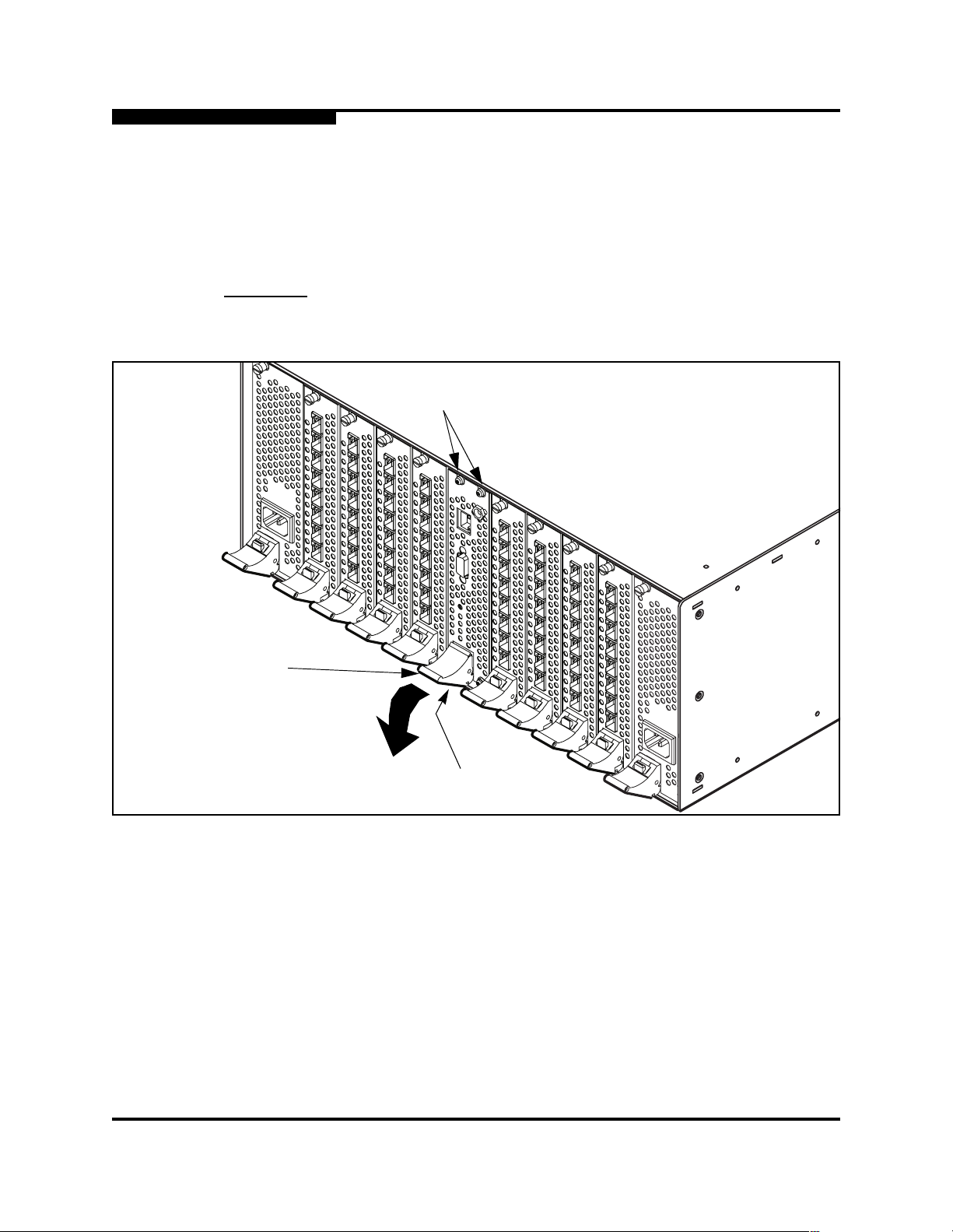
6 – Removal/Replacement
CPU Module
8. To unfasten the CPU module, disconnect the Ethernet and serial cables
from the CPU module. Connect an ESD wrist strap to a ground point on the
chassis or rack. Using a flat-bladed screwdriver, loosen the four captive
screws at the top and bottom of the CPU module faceplate as shown in
Figure 6-1. The bottom-left screw is under the latch.
CAUTION!
Latch
The CPU module contains sensitive logic components. To avoid
damage to the module, do not touch the CPU module components.
Screws
Screws
Figure 6-1. Removing the CPU Module
9. To remove the CPU module, grasp the latch and rotate it downward to
disengage the CPU module from the backplane connector. Carefully slide
the CPU module out of the slot.
6-4 59043-01 A

6.2.2
Installing the CPU Module
To install the CPU module, do the following:
1. Slide the CPU module into the slot guide until it makes contact with the
backplane connector . Rotate the blade latch upward to l ock the CPU module
in place. Fasten the screws.
2. Reconnect the Ethernet and serial cable to the CPU module.
3. Power up the switch. Reconnect both power cords to the power supply
modules.
4. Observe the Heartbeat LED. It should blink once per second. If the
Heartbeat LED is showing a different blink pattern, refer to”Heartbeat LED
Blink Patterns” on page 5-1 for diagnostic procedures or contact your
authorized maintenance provider.
5. Verify the POST results. Open a Telnet session with the default IP address
(10.0.0.1), and enter the Show Slot command to display the diagnostic
status for the CPU module. Refer to the ”Show Command” on page B-44.
You could also display the diagnostic status using the Switch tab or Blade
Info tab of the SANbox Manager facepla te display. Refer to the SANbox2-64
Switch Management User’s Guide.
6 – Removal/Replacemen t
CPU Module
Note: A “Failed” status could indicate a faulty blade or module. Enter
the Show POST Log command for more information or contact
your authorized maintenance provider.
6. Compare firmware versions. Open a Telnet session and enter the Show
Version command to determine the firmware version.
■ If the firmware versions on the two CPU modules are the same,
proceed to step 9 to restore the switch configuration.
■ If the firmware versions are different, proceed to step 7 to install
firmware.
7. Install firmware. Acquire the firmware image file from your own storage or
you can download firmware from the QLogic web site.
59043-01 A 6-5

6 – Removal/Replacement
CPU Module
8. Load the image file on the switch. Move to the directory that contains the
firmware image file and open an FTP session. When prompted, enter the
account name (images) and password (images). Enter the Put command
and specify the name of the image file.
9. Unpack the image file. Press and hold the Maintenance button for four
seconds to place the switch in maintenance mode. Open a Telnet session
and log in with the account name “prom” and password “prom”.
10. Select option 1 from the maintenance menu. When prompted for a file name
enter the firmware image file name. After the unpacking is complete, select
option 7 to reset the switch.
ftp 10.0.0.1
User: images
Password: images
ftp> binary
ftp> put image_file
ftp> bye
Telnet 10.0.0.1
Sanbox2 login: prom
Password: prom
0) Exit
1) Image Unpack
2) Reset Network Config
3) Reset Password File
4) Copy Log Files
5) Remove Switch Config
6) Remake Filesystem
7) Reset Switch
Option:
Image filename: image_file
Unpacking ’filename’, please wait...
Unpackage successful.
0) Exit
1) Image Unpack
2) Reset Network Config
3) Reset Password File
4) Copy Log Files
5) Remove Switch Config
6) Remake Filesystem
7) Reset Switch
Option:
1
7
6-6 59043-01 A

6 – Removal/Replacemen t
I/O Blades
11. Restore switch configuration. Move to the directory that contains the
configdata file that you downloaded earlier . Use FTP to upload this file from
the management workstation to the switc h.
ftp 10.0.0.1
User: images
Password: images
ftp> binary
ftp> put configdata
ftp> bye
12. Open a Telnet session and enter the Config Res tore command to restore the
switch configuration. Refer to ”Config Command” on page B-7 for more
information. If you archived the configurat ion using SANbox Manager, you
can restore the switch configuration using the SANbox Manager Restore
function.
13. Observe the Heartbeat LED. It should blink once per second. If the
Heartbeat LED is showing a different blink pattern, refer to ”Heartbeat LED
Blink Patterns” on page 5-1 for diagnostic procedures or contact your
authorized maintenance provider.
6.3
I/O Blades
14. Reconnect the Fiber Channel port cables according to their labels.
Disconnect the cross-over Ethernet cable and reconnect the original
Ethernet cable if there was one.
You can remove and install I/O blades while the switch is operati ng. The fol lowing
instructions assume that the switch is operati ng. If you want to maint ain serv ice to
the devices connected to a particular blade while it is being replaced, transfer the
Fibre Channel cables to another blade. To remove an I/O blade blank panel,
simply disengage the latch and slide the blank panel from the switch.
CAUTION!
To replace an I/O blade, do the following:
1. Label the Fibre Channel port cabl es by port number. Ports on each I/O blade
are numbered 0-7 from top to bottom. Disconnect the Fibre Channel port
cables.
The I/O blade contains sensitive logic components. To avoid
damage to the I/O blade, do not touch the I/O blade components.
Keep I/O blades in ESD protective containers or anti-static bags
when not in use.
2. Put on an ESD wrist strap, and connect it to the ground jack on the CPU
module shown in Figure 6-2 or some other ground point on the chassis.
59043-01 A 6-7

6 – Removal/Replacement
I/O Blades
3. Open a Telnet session and enter the Hotswap command. You can also
replace an I/O blade using the SANbox Manager application. Perform the
tasks as prompted:
Note: The switch will become unresponsive if you do not perform the tasks
4. Choose the Replace task (1).
as prompted. If the switch becomes unresponsive, you must power
cycle the switch.
SANbox2-64 (admin) #> hotswap
This command will guide you through the hotswap process.
If this process is not followed exactly, then a seamless
transition cannot be guaranteed and a switch power cycle
will be required.
The following procedures may be performed:
1) Replace installed IO blade
2) Insert an IO blade
3) Remove an IO blade
4) Exit this process
Which procedure above do you want to initiate?
(1-4): [4] 1
5. Choose the slot number (6 for example).
Which IO blade (indexed by slot number) do you want
to replace? (1,2,3,4,6,7,8,9): [1] 6
Are you sure you want to replace the IO blade in slot 6?
(y/n): [n] y
6. After confirming that you wan t to repl ace the I/O blade, the Port Status LEDs
will begin to flash green to positively identify the selected I/O blade.
Disconnect all cables from the selected I/O blade.
WARNING!!
CAUTION!
Vol tage is present in an open slot when the swi tch is operating. To
avoid personal injury or damage to components, do not place
hands or objects into a slot.
To avoid damaging the latch mechanism, press the red release
button all the way in before rotating the latch.
6-8 59043-01 A
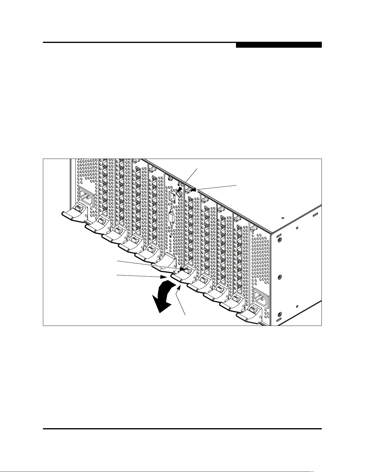
6 – Removal/Replacemen t
I/O Blades
7. Using a flat-bladed screwdriver, loosen the captive screws at the top and
bottom of the I/O blade faceplate as shown in Figure 6-2. The bottom screw
is under the latch. Grasp the latch and press the red release butto n, then
rotate the latch downward to disengage the I/O blade from the backplane
connector. Carefully slide the I/O blade out of the slot.
Remove all connections from the IO blade in slot 6.
Remove the IO blade in slot 6 from the chassis.
Please confirm that these steps have been accomplished by
pressing the ENTER key.
Hotswap IO blade removal sub-procedure successfully
completed.
Ground Jack
Screw
Release Button
Latch
Figure 6-2. Removing an I/O Blade
8. To install a new I/O blade, enter “y”.
Do you want to continue with the replacement procedure?
(y/n): [n] y
Screw
59043-01 A 6-9

6 – Removal/Replacement
I/O Blades
9. Slide the I/O blade into the slot guide until it makes contact with the
backplane connector. Rotate the blade latch upward to lock the I/O bla de in
place. Fasten the screws.
10. After confirming that the I/O blade has been installed, the Port Status LEDs
will flash amber in port number sequence, then the Port Status LEDs will
flash green. Reconnect the Fiber Channel port cables accordi ng to their
labels.
11. Verify the POST results. The I/O blade diagnostic stat us appears in the
dialog. The status should be "Passed".
Insert the IO blade into the chassis in slot 6.
Attach all connections, if any, to the IO blade in s lot 6.
Please confirm that these steps have been accomplished by
pressing the ENTER key.
Hotswap IO blade process successfully completed.
Diagnostics has been run on the IO blade in slot 7:
Passed
Note: A “Failed” status could indicate a faulty blade or module. Enter
the Show POST Log command for more information or contact
your authorized maintenance provider.
12. The system checks the I/O blades for matching Zi rcon processor fi rmware. If
any of the I/O blades are not compatible, an alarm message will be
generated indicating that a Zircon firmware mismatch has occurred. To
display the alarm log, enter the Show Al arm comman d or use t he Alar m Log
tab in the SANbox Manager faceplate di splay. Refer to ”Show Command” on
page B-44 for more information. If a mismatch does occur, cont act your
authorized maintenance provider.
SANbox2-64 #> show alarm
[9][Wed Jan 16 13:32:19.500 2003]
[A4101][0xdd0072c2.329][IO-1 Zircon firmware mismatch:
rev 0.5, should be perhaps rev 0.7]
6-10 59043-01 A
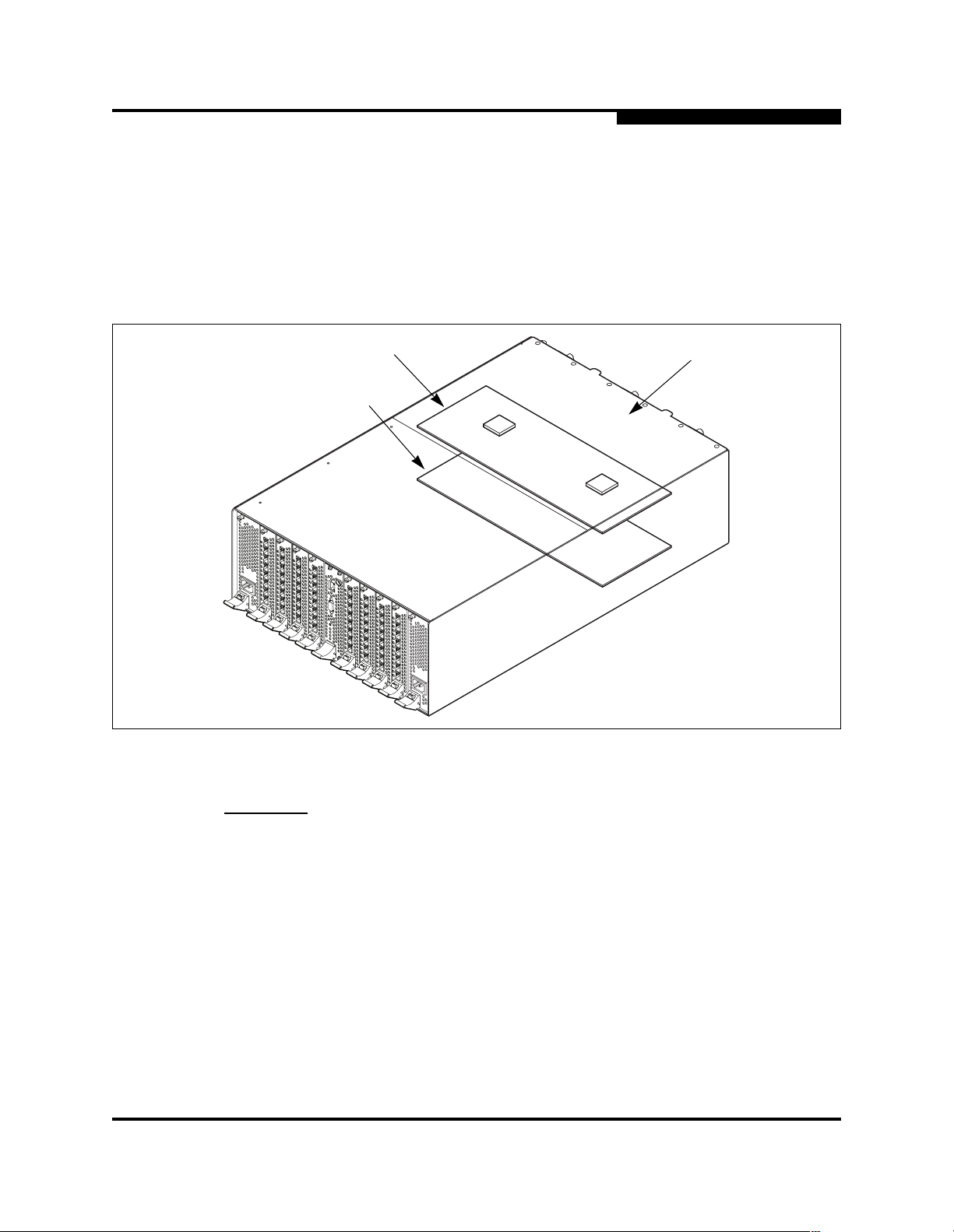
6.4
Cross-Connect Blades
The SANbox2-64 switch contains two CC blades: one in slot 11 (CC blade 0) and
the other in slot 12 (CC blade 1) as shown in Figure 6-3. You access slot 11 by
removing the top-rear switch cover. To access slot 12, you remove the bottomrear switch cover. Other than this, the procedure for replacing either CC blade is
the same.
6 – Removal/Replacemen t
Cross-Connect Blades
Slot 11
Slot 12
Figure 6-3. CC Blade Slots
Top-Rear
Switch Cover
CAUTION! Always use an ESD wrist strap when removing and installing a CC
blade.
The CC blade contains sensitive logic components. To avoid
damage to the module, do not touch the CPU module components.
Keep the CC blade in an ESD protective container or anti-static
bag when not in use.
59043-01 A 6-11

6 – Removal/Replacement
Cross-Connect Blades
6.4.1
Removing a CC Blade
To remove a CC blade, do the following:
1. Power down the switch. Isolate the switch from the fabric. Open a Telnet
session and enter the Shutdown command. Disconnect the power cords
from the power supplies.
telnet <ip_address>
SANbox2 Login: admin
Password: password
Sanbox2-64 #> admin start
Sanbox2-64 (admin) #> shutdown
The switch will shutdown. Please confirm (y/n): [n] y
Shutdown in progress...
Please wait at least 20 seconds before powering off
the switch or loss of data may result.
2. Label the Fibre Channel port cables by slot number and port number. I/O
blade slots are numbered 1–4 and 6–9. Ports on each I/O blade are
numbered 0–7 from top to b o tto m.
3. Put on an ESD wrist strap. Connect it t o the ground jack on the CPU module
or to another chassis ground point. Disconnect Fibre Channel port cables.
4. Disconnect Ethernet and serial cables.
WARNING!!
5. Remove the switch from the rack. Using a crosshead screw driver, remove
the screws that secure the switch brackets to the rack. Slide the switch out
of the rack until the rail latches drop down to stop the switch. Lift up on the
latches on both sides and finish removing the switch.
Two peopl e are required to safel y lift and i nstall t he switch into a
cabinet. To avoid personal injury or damage to the switch,
arrange for assistance
6-12 59043-01 A

6 – Removal/Replacemen t
Cross-Connect Blades
6. Remove the switch cover. Use a medium crosshead screw driver to remove
the four screws on each side and the six screws on top as shown in
Figure 6-4. Lif t a nd remove t he s witch cover and set i t asi de. Put on an ESD
wrist strap and connect it to ground.
Figure 6-4. Switch Cover Removal
7. Remove the CC blade. Loosen the six screws (1) that f asten the CC blade to
the chassis as shown in Figure 6-5, but do not remove them. The three
screws nearest the latches (2) need only be loosened a couple turns. The
three screws nearest the backplane ( 3) must be backed off abou t 3/8 of inch
to allow enough clearance to remove the blade.
1
1
2
1
2
3
1
1
Figure 6-5. CC Blade Removal
59043-01 A 6-13

6 – Removal/Replacement
Cross-Connect Blades
8. Disconnect the CC blade from backplane. Grasp both latches with the
thumbs. Open both latches together a little at a time to disenga ge the CC
blade from the backplane.
9. Lift CC blade from switch. Using the thumbs under the open latches, lift the
latch edge of the CC blade up enough to get a better grip. Gently lift the CC
blade from the switch. If the CC blade will not come of f the screws nearest
the backplane, back the screws off a little more. Place the CC blade in an
anti-static bag.
6.4.2
Installing a CC Blade
To install a CC blade, do the following:
1. Put on an ESD wrist strap. Connect it t o the ground jack on the CPU module
or to another chassis ground point.
2. Remove the new CC blade from its packaging. Open both latches all the
way. Holding the CC blade by the latches, place the blade in the switch.
Center the blade key holes over the screws nearest the backplane, then
lower the blade over the remaining screws as shown in Figure 6-6.
Figure 6-6. Installing a CC Blade
3. Using the thumbs, close both la tches t o seat t he CC blade in the backpl ane.
When securing the latches, be sure that the latch engage s the chassis tab.
Using a crosshead screw driver, fasten the blade screws finger tight
beginning with the two middle screws.
4. Replace the switch cover and fasten all the screws.
6-14 59043-01 A

6 – Removal/Replacemen t
Cross-Connect Blades
WARNING!!
5. With an assistant, slide the switch into the rack. Fasten the switch brackets
to the rack with screws.
6. Reconnect the Ethernet cable to the CPU module. Reconnect the power
cords to the power supply modules to power up the switch.
7. Confirm the power supply module status. Do one of the following:
■ Open a Telnet session and enter the Show Slot command to display
the operational status of the CC blades. Refer to the ”Show Command”
on page B-44.
■ Observe the CC blade status in the Switch or the Blade Info data
windows of the SANbox Manager faceplate display. Refer to the
SANbox2-64 Switch Management User’s Guide.
Note: A “Failed” status could indicate an improperly seated or faulty
Two peopl e are required to safel y lift and i nstall t he switch into a
cabinet. To avoid personal injury or damage to the switch,
arrange for assistance
blade. Enter the Show POST Log command for more informati on
or contact your authorized maintenance provider.
59043-01 A 6-15

6 – Removal/Replacement
Power Supply Modules
6.5
Power Supply Modules
The power supply modules are hot pluggable. This means you can remove or
install one of the t wo functioning power supply modules without di srupting servi ce.
The power supply modules are also interchangeable; that is, any power supply
module will fit in slot #0 or slot #10.
6.5.1
Removing a Power Supply Module
To remove a power supply module, do the following:
WARNING!!
CAUTION!
1. Disconnect the power cord from the power supply module.
2. Connect an ESD wrist strap to the gr ound jack on th e CPU module shown in
Figure 6-7 or some other ground point on the chassis .
3. Using a flat-blade screw driver, loosen the captive screws at the top and
bottom of the module faceplate as shown in Figure 6-7. The bottom screw is
under the latch.
CAUTION!
The power supply module faceplate and internal surfaces can
become very hot. Handle with care.
Vol tage is present in an open slot when the swi tch is operating. To
avoid personal injury or damage to surrounding components, do
not place hands or objects into an open slot.
Always use an ESD wrist strap when removing and installing a
power supply module. The power supply module contains
sensitive electronic components. To avoid damage to the power
supply module, do not touch the module components.
Keep the power supply module in an ESD protective container or
anti-static bag when not in use.
To avoid damaging the latch mechanism, press the red release
button all the way in before rotating the latch.
4. Grasp the latch and press the red release button, then rotate the latch
downward to disengage the module from the bac kplane connector. Carefully
slide the module out of the slot.
CAUTION!
6-16 59043-01 A
To prevent overheating and possible damage to the switch, do not
operate the switch with an empty slot any longer than it takes to
install a new power supply module.
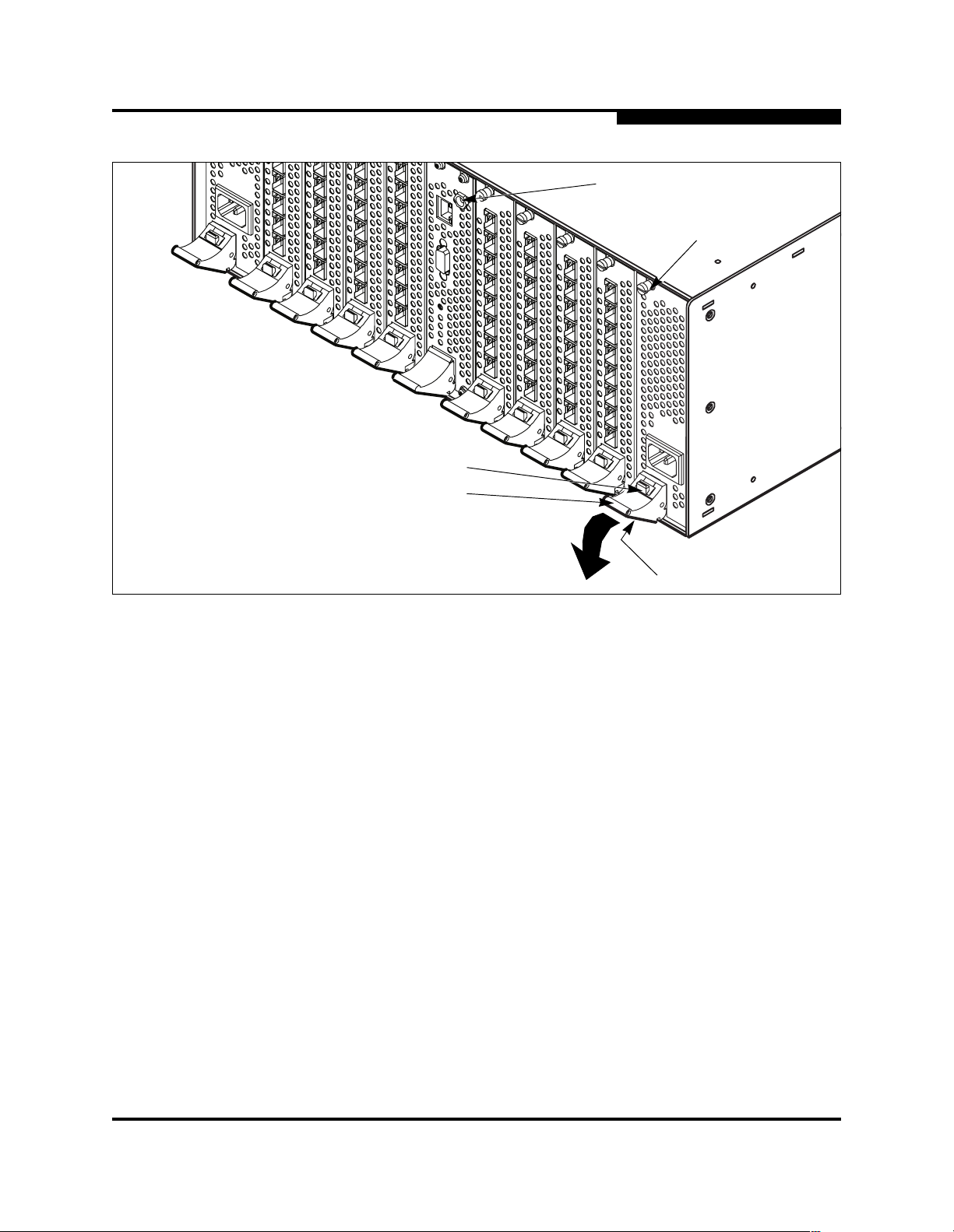
6 – Removal/Replacemen t
Power Supply Modules
Ground Jack
Screw
Release Button
Latch
Figure 6-7. Removing a Power Supply Module
6.5.2
Installing a Power Supply Module
To install a power supply module, do the following:
1. Slide the power supply module into the slot guide unt il it contacts the
backplane.
2. Rotate the blade latch upward to lock the power supply module in place.
Fasten the screws.
3. Reconnect the power cord to the power supply module and confirm that the
Output Power LED illuminates.
4. Confirm the power supply module status. Do one of the following:
■ Open a Telnet session and enter the Show Chassis command to
display the operational status of the power supply modules. Refer to
the ”Show Command” on page B-44.
■ Observe the power supply status in the Switch data window of the
SANbox Manager topology display. Refer to the SANbox2-64 Switch
Management User’s Guide.
Screw
59043-01 A 6-17
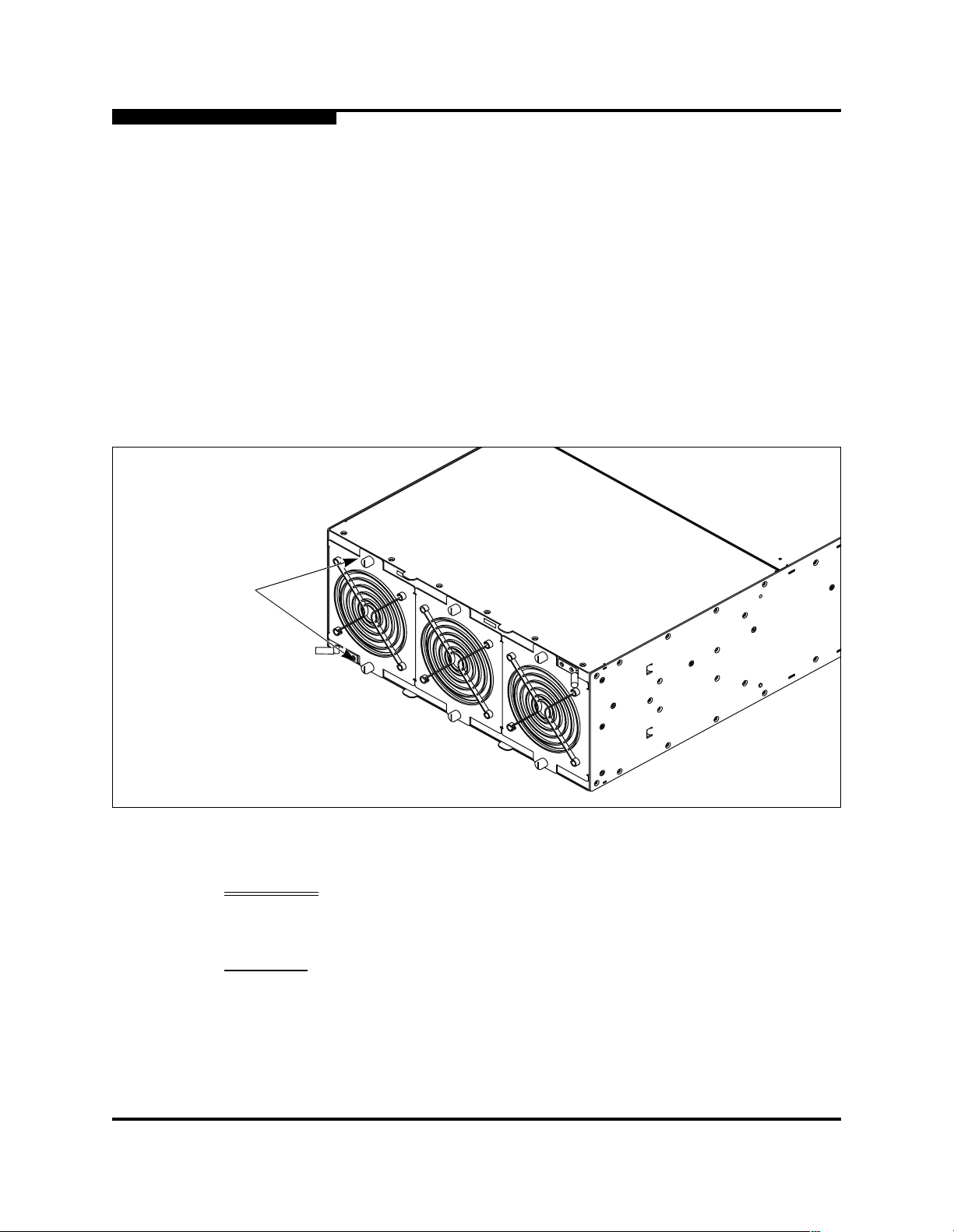
6 – Removal/Replacement
Fans
6.6
Fans
The fans are hot pluggable. This means you can remove or install one of the fans
while the switch is operating without disrupting service. The fan is completely
enclosed, so there is no risk of injury from the fan bl ades. The fans are also
interchangeable; that is, any fan wil l fit in any bay. Before removing a fan, connect
an ESD wrist strap to a ground point on the chassis or rack.
6.6.1
Removing a Fan
To remove a fan, loosen the two captive screws shown in Figure 6-8 with a flatblade screw driver. Grasp the fan by the screws and pull firmly to disengage the
fan from the backplane connector. Slide the fan out of the chassis.
Screws
Figure 6-8. Removing a Fan
WARNING!! Vol tage is present in an open bay when the switch is operat ing. To
avoid personal injury, do not place hands or objects into an open
bay.
CAUTION!
Replacement fans must be compatible with the switch air flow
direction of the other fans. Installing a fan with an opposing air
flow direction could lead to an over temperature condition.
To avoid overheating, do not operat e the switch without a fan any
longer than it takes to install a new fan.
6-18 59043-01 A

6.6.2
Installing a Fan
To install a fan, do the following:
1. Confirm that the new fan has the same a ir flow dir ectio n as the old fan. Eac h
2. Slide the fan into the bay until it is firml y seated and faste n the screws. A fan
3. Confirm the fan status. Do one of the following:
6 – Removal/Replacemen t
Fans
fan has a label indicating the air flow direction.
will fit in any bay.
■ Open a Telnet session and enter the Show Chassis command to
display the operational status of the fans. Refer to the ”Show
Command” on page B-44.
■ Observe the fan status in the Switch data window of the SANbox
Manager topology display. Refer to the SANbox2-64 Switch
Management User’s Guide.
59043-01 A 6-19

6 – Removal/Replacement
Fans
Notes
6-20 59043-01 A
 Loading...