

Page 1

Inst allation Guide
QLogic intelligent Storage Router (iSR)
6200 Series
ISR651101-00 J
Page 2

Installation Guide QLogic intelligent Storage Router (iSR)
6200 Series
Information furnished in this manual is believed to be accurate and reliable. However, QLogic Corporation assumes no
responsibility for its use, nor for any infringements of patents or other rights of third parties which may result from its
use. QLogic Corporation reserves the right to change product specifications at any time without notice. Applications
described in this document for any of these products are for illustrative purposes only. QLogic Corporation makes no
representation nor warranty that such applications are suitable for the specified use without further testing or
modification. QLogic Corporation assumes no responsibility for any errors that may appear in this document.
Document Revision History
Revision A, March 20, 2009
Revision B, May 24, 2009
Revision C, November 30, 2009
Revision D, May 14, 2010
Revision E, October 29, 2010
Revision F, November 8, 2010
Revision G, September 28, 2011
Revision H, May 18, 2012
Revision J, December 02, 2012
Changes Sections Affected
Updated Documentation Conventions “Documentation Conventions” on page xiii
Updated Technical Support, Training, Contact
Information, and Knowledge Base
“Technical Support” on page xix, “Training” on
page xx
Added China Compulsory Certification warnings “China Compulsory Certification (CCC) Warnings”
on page xviii
Added Simplified Chinese translation to warnings
Added French, German, Spanish, and Simplified
“ 警告 ” on page 3-5, “ 警告 ” on page 3-9
“Connecting the Router to AC Power” on page 3-7
Chinese to the warning
ii ISR651101-00 J
Page 3

Table of Contents
Preface
Intended Audience . . . . . . . . . . . . . . . . . . . . . . . . . . . . . . . . . . . . . . . . . . . . xi
What’s in This Guide . . . . . . . . . . . . . . . . . . . . . . . . . . . . . . . . . . . . . . . . . . xi
Related Materials . . . . . . . . . . . . . . . . . . . . . . . . . . . . . . . . . . . . . . . . . . . . . xii
Documentation Conventions . . . . . . . . . . . . . . . . . . . . . . . . . . . . . . . . . . . . xiii
Communications Statements . . . . . . . . . . . . . . . . . . . . . . . . . . . . . . . . . . . . xv
Federal Communications Commission (FCC) Class A Statement . . . xv
Canadian Department of Communications Class A
Compliance Statement . . . . . . . . . . . . . . . . . . . . . . . . . . . . . . . . . . . xv
Avis de conformité aux normes du ministère des Communications du
Canada . . . . . . . . . . . . . . . . . . . . . . . . . . . . . . . . . . . . . . . . . . . . . . . xv
CE Statement . . . . . . . . . . . . . . . . . . . . . . . . . . . . . . . . . . . . . . . . . . . xvi
VCCI Class A Statement . . . . . . . . . . . . . . . . . . . . . . . . . . . . . . . . . . . xvii
BSMI Class A Statement . . . . . . . . . . . . . . . . . . . . . . . . . . . . . . . . . . . xvii
Laser Safety Information . . . . . . . . . . . . . . . . . . . . . . . . . . . . . . . . . . . . . . . xvii
Electrostatic Discharge Sensitivity (ESDS) Precautions . . . . . . . . . . . . . . . xviii
China Compulsory Certification (CCC) Warnings. . . . . . . . . . . . . . . . . . . . . xviii
Accessible Parts. . . . . . . . . . . . . . . . . . . . . . . . . . . . . . . . . . . . . . . . . . . . . . xviii
License Agreements. . . . . . . . . . . . . . . . . . . . . . . . . . . . . . . . . . . . . . . . . . . xviii
Technical Support. . . . . . . . . . . . . . . . . . . . . . . . . . . . . . . . . . . . . . . . . . . . . xix
Downloading Updates . . . . . . . . . . . . . . . . . . . . . . . . . . . . . . . . . . . . . xix
Training . . . . . . . . . . . . . . . . . . . . . . . . . . . . . . . . . . . . . . . . . . . . . . . . xx
Contact Information . . . . . . . . . . . . . . . . . . . . . . . . . . . . . . . . . . . . . . . xx
Knowledge Database . . . . . . . . . . . . . . . . . . . . . . . . . . . . . . . . . . . . . xx
1 Introduction
Router Capabilities and Features. . . . . . . . . . . . . . . . . . . . . . . . . . . . . . . . . 1-1
Licensed Features . . . . . . . . . . . . . . . . . . . . . . . . . . . . . . . . . . . . . . . . . . . . 1-2
Data Migration . . . . . . . . . . . . . . . . . . . . . . . . . . . . . . . . . . . . . . . . . . . 1-2
Remote SAN Island Connectivity . . . . . . . . . . . . . . . . . . . . . . . . . . . . . . . . . 1-2
iSR6200 Router Chassis . . . . . . . . . . . . . . . . . . . . . . . . . . . . . . . . . . . . . . . 1-3
Power and Cooling Module (PCM). . . . . . . . . . . . . . . . . . . . . . . . . . . . . . . . 1-5
iSR6200 Router Blades . . . . . . . . . . . . . . . . . . . . . . . . . . . . . . . . . . . . . . . . 1-6
ISR651101-00 J iii
Page 4

Installation Guide QLogic intelligent Storage Router (iSR)
6200 Series
iSR6200 Router Family Models. . . . . . . . . . . . . . . . . . . . . . . . . . . . . . 1-7
iSR6260 Router Blade . . . . . . . . . . . . . . . . . . . . . . . . . . . . . . . . 1-7
iSR6250 Router Blade . . . . . . . . . . . . . . . . . . . . . . . . . . . . . . . . 1-8
iSR6240 Router Blade . . . . . . . . . . . . . . . . . . . . . . . . . . . . . . . . 1-9
Router Blade LEDs . . . . . . . . . . . . . . . . . . . . . . . . . . . . . . . . . . . . . . . 1-9
Heartbeat LED (Green) . . . . . . . . . . . . . . . . . . . . . . . . . . . . . . . 1-9
System Fault LED (Amber). . . . . . . . . . . . . . . . . . . . . . . . . . . . . 1-10
Input Power LED (Green) . . . . . . . . . . . . . . . . . . . . . . . . . . . . . . 1-10
Beacon Indicator (Blue) . . . . . . . . . . . . . . . . . . . . . . . . . . . . . . . 1-10
Maintenance Button. . . . . . . . . . . . . . . . . . . . . . . . . . . . . . . . . . . . . . . 1-11
Reset a Router Blade . . . . . . . . . . . . . . . . . . . . . . . . . . . . . . . . . 1-11
Reset and Select Boot Image. . . . . . . . . . . . . . . . . . . . . . . . . . . 1-12
Reset IP Address . . . . . . . . . . . . . . . . . . . . . . . . . . . . . . . . . . . . 1-12
Enable DHCP . . . . . . . . . . . . . . . . . . . . . . . . . . . . . . . . . . . . . . . 1-12
Restore Factory Defaults . . . . . . . . . . . . . . . . . . . . . . . . . . . . . . 1-12
Fibre Channel Port LEDs. . . . . . . . . . . . . . . . . . . . . . . . . . . . . . . . . . . 1-13
Fibre Channel Transceivers . . . . . . . . . . . . . . . . . . . . . . . . . . . . . . . . 1-14
Gigabit Ethernet Port LEDs . . . . . . . . . . . . . . . . . . . . . . . . . . . . . . . . . 1-15
Ethernet Port—Management. . . . . . . . . . . . . . . . . . . . . . . . . . . . . . . . 1-15
Serial Port . . . . . . . . . . . . . . . . . . . . . . . . . . . . . . . . . . . . . . . . . . . . . . 1-16
2 Planning
Devices. . . . . . . . . . . . . . . . . . . . . . . . . . . . . . . . . . . . . . . . . . . . . . . . . . . . . 2-1
Device Access . . . . . . . . . . . . . . . . . . . . . . . . . . . . . . . . . . . . . . . . . . . . . . . 2-2
Fibre Channel . . . . . . . . . . . . . . . . . . . . . . . . . . . . . . . . . . . . . . . . . . . 2-2
iSCSI . . . . . . . . . . . . . . . . . . . . . . . . . . . . . . . . . . . . . . . . . . . . . . . . . . 2-2
Fibre Channel Switches Required for VPGroups . . . . . . . . . . . . . . . . . . . . . 2-2
Fibre Channel Performance . . . . . . . . . . . . . . . . . . . . . . . . . . . . . . . . . . . . . 2-2
Distance. . . . . . . . . . . . . . . . . . . . . . . . . . . . . . . . . . . . . . . . . . . . . . . . 2-2
Bandwidth . . . . . . . . . . . . . . . . . . . . . . . . . . . . . . . . . . . . . . . . . . . . . . 2-3
Latency . . . . . . . . . . . . . . . . . . . . . . . . . . . . . . . . . . . . . . . . . . . . . . . . 2-3
iSCSI Performance. . . . . . . . . . . . . . . . . . . . . . . . . . . . . . . . . . . . . . . . . . . . 2-3
Distance. . . . . . . . . . . . . . . . . . . . . . . . . . . . . . . . . . . . . . . . . . . . . . . . 2-3
Bandwidth . . . . . . . . . . . . . . . . . . . . . . . . . . . . . . . . . . . . . . . . . . . . . . 2-3
Latency . . . . . . . . . . . . . . . . . . . . . . . . . . . . . . . . . . . . . . . . . . . . . . . . 2-4
Performance Tuning. . . . . . . . . . . . . . . . . . . . . . . . . . . . . . . . . . . . . . . . . . . 2-4
Topology . . . . . . . . . . . . . . . . . . . . . . . . . . . . . . . . . . . . . . . . . . . . . . . . . . . . 2-7
High Availability . . . . . . . . . . . . . . . . . . . . . . . . . . . . . . . . . . . . . . . . . . . . . . 2-7
Management . . . . . . . . . . . . . . . . . . . . . . . . . . . . . . . . . . . . . . . . . . . . . . . . 2-7
Recovery . . . . . . . . . . . . . . . . . . . . . . . . . . . . . . . . . . . . . . . . . . . . . . . . . . . 2-8
iv ISR651101-00 J
Page 5

Services . . . . . . . . . . . . . . . . . . . . . . . . . . . . . . . . . . . . . . . . . . . . . . . . . . . . 2-8
Security . . . . . . . . . . . . . . . . . . . . . . . . . . . . . . . . . . . . . . . . . . . . . . . . . . . . 2-9
3 Installation
Site Requirements . . . . . . . . . . . . . . . . . . . . . . . . . . . . . . . . . . . . . . . . . . . . 3-1
Management Workstation . . . . . . . . . . . . . . . . . . . . . . . . . . . . . . . . . . 3-1
Power Requirements. . . . . . . . . . . . . . . . . . . . . . . . . . . . . . . . . . . . . . 3-2
Environmental Conditions . . . . . . . . . . . . . . . . . . . . . . . . . . . . . . . . . . 3-2
Installing the iSR6200 Router. . . . . . . . . . . . . . . . . . . . . . . . . . . . . . . . . . . . 3-2
Pre-installation Check List. . . . . . . . . . . . . . . . . . . . . . . . . . . . . . . . . . 3-3
Mounting the Router . . . . . . . . . . . . . . . . . . . . . . . . . . . . . . . . . . . . . . 3-5
Installing the Transceivers. . . . . . . . . . . . . . . . . . . . . . . . . . . . . . . . . . 3-6
Connecting the Router to AC Power . . . . . . . . . . . . . . . . . . . . . . . . . . 3-7
Connecting the Management Workstation to the Router. . . . . . . . . . . 3-10
Configuring the Management Workstation . . . . . . . . . . . . . . . . . . . . . 3-11
Setting the Workstation IP Address . . . . . . . . . . . . . . . . . . . . . . 3-11
Configuring the Workstation Serial Port . . . . . . . . . . . . . . . . . . . 3-12
Installing SANsurfer Router Manager . . . . . . . . . . . . . . . . . . . . . . . . . 3-13
Downloading the SANsurfer Router Manager Installer. . . . . . . . 3-13
Windows Installation. . . . . . . . . . . . . . . . . . . . . . . . . . . . . . . . . . 3-15
Linux Installation. . . . . . . . . . . . . . . . . . . . . . . . . . . . . . . . . . . . . 3-15
Mac OS X Installation . . . . . . . . . . . . . . . . . . . . . . . . . . . . . . . . . 3-15
Starting SANsurfer Router Manager . . . . . . . . . . . . . . . . . . . . . . . . . . 3-16
Configuring the Router . . . . . . . . . . . . . . . . . . . . . . . . . . . . . . . . . . . . 3-16
Connecting Cable Devices to the Router . . . . . . . . . . . . . . . . . . . . . . 3-17
Installing New Firmware . . . . . . . . . . . . . . . . . . . . . . . . . . . . . . . . . . . . . . . . 3-17
Using SANsurfer Router Manager to Install Firmware . . . . . . . . . . . . 3-18
Using the CLI to Install Firmware . . . . . . . . . . . . . . . . . . . . . . . . . . . . 3-18
Installation Guide QLogic intelligent Storage Router (iSR)
6200 Series
4 Configuration
Enabling Virtual Port Groups . . . . . . . . . . . . . . . . . . . . . . . . . . . . . . . . . . . . 4-2
Zoning Virtual Port Groups on the SAN . . . . . . . . . . . . . . . . . . . . . . . . . . . . 4-9
Configuring Fibre Channel Array Hosts and LUN Assignments. . . . . . . . . . 4-12
Connecting iSCSI Hosts to the iSR6200 . . . . . . . . . . . . . . . . . . . . . . . . . . . 4-16
Controlling per-Host LUN Access on the iSR6200. . . . . . . . . . . . . . . . . . . . 4-22
5 Fibre Channel over IP
FCIP Attributes . . . . . . . . . . . . . . . . . . . . . . . . . . . . . . . . . . . . . . . . . . . . . . . 5-1
Configuring FCIP . . . . . . . . . . . . . . . . . . . . . . . . . . . . . . . . . . . . . . . . . . . . . 5-2
Configuring an FCIP Route Using the CLI. . . . . . . . . . . . . . . . . . . . . . 5-4
E_Port Extension. . . . . . . . . . . . . . . . . . . . . . . . . . . . . . . . . . . . . . . . . 5-6
ISR651101-00 J v
Page 6

Installation Guide QLogic intelligent Storage Router (iSR)
6200 Series
F_Port Extension. . . . . . . . . . . . . . . . . . . . . . . . . . . . . . . . . . . . . . . . . 5-8
Determining WAN Characteristics . . . . . . . . . . . . . . . . . . . . . . . . . . . . 5-10
Round-Trip Time. . . . . . . . . . . . . . . . . . . . . . . . . . . . . . . . . . . . . 5-11
Link Data Rate . . . . . . . . . . . . . . . . . . . . . . . . . . . . . . . . . . . . . . 5-12
Link Quality. . . . . . . . . . . . . . . . . . . . . . . . . . . . . . . . . . . . . . . . . 5-12
Firewall . . . . . . . . . . . . . . . . . . . . . . . . . . . . . . . . . . . . . . . . . . . . . . . . 5-15
Data Compression. . . . . . . . . . . . . . . . . . . . . . . . . . . . . . . . . . . . . . . . 5-16
Bandwidth Limiting . . . . . . . . . . . . . . . . . . . . . . . . . . . . . . . . . . . . . . . 5-16
TCP Window Settings . . . . . . . . . . . . . . . . . . . . . . . . . . . . . . . . . . . . . 5-17
Router TCP Window Setup . . . . . . . . . . . . . . . . . . . . . . . . . . . . 5-22
6 Diagnostics and Tr oubleshooting
Chassis Diagnostics . . . . . . . . . . . . . . . . . . . . . . . . . . . . . . . . . . . . . . . . . . . 6-1
Input Power LED is Off . . . . . . . . . . . . . . . . . . . . . . . . . . . . . . . . . . . . 6-2
System Fault LED is On . . . . . . . . . . . . . . . . . . . . . . . . . . . . . . . . . . . 6-2
Power-On Self-Test Diagnostics. . . . . . . . . . . . . . . . . . . . . . . . . . . . . . . . . . 6-2
LED Blink Patterns . . . . . . . . . . . . . . . . . . . . . . . . . . . . . . . . . . . . . . . . . . . . 6-2
Heartbeat Blink Pattern . . . . . . . . . . . . . . . . . . . . . . . . . . . . . . . . . . . . 6-3
System Error Blink Pattern . . . . . . . . . . . . . . . . . . . . . . . . . . . . . . . . . 6-3
Management Port IP Address Conflict Blink Pattern. . . . . . . . . . . . . . 6-3
Over-Temperature Blink Pattern . . . . . . . . . . . . . . . . . . . . . . . . . . . . . 6-4
Recovering a Router . . . . . . . . . . . . . . . . . . . . . . . . . . . . . . . . . . . . . . . . . . 6-4
7 Removal and Replacement
SFP Transceivers. . . . . . . . . . . . . . . . . . . . . . . . . . . . . . . . . . . . . . . . . . . . . 7-1
iSR6200 Chassis Blades . . . . . . . . . . . . . . . . . . . . . . . . . . . . . . . . . . . . . . . 7-1
Dual-Blade Installation. . . . . . . . . . . . . . . . . . . . . . . . . . . . . . . . . . . . . 7-2
Removing the Failed Blade . . . . . . . . . . . . . . . . . . . . . . . . . . . . 7-2
Installing the Replacement Blade . . . . . . . . . . . . . . . . . . . . . . . . 7-3
Single-Blade Installation . . . . . . . . . . . . . . . . . . . . . . . . . . . . . . . . . . . 7-4
Removing the Failed Blade . . . . . . . . . . . . . . . . . . . . . . . . . . . . 7-5
Installing the Replacement Blade . . . . . . . . . . . . . . . . . . . . . . . . 7-8
Power and Cooling Modules . . . . . . . . . . . . . . . . . . . . . . . . . . . . . . . . . . . . 7-10
Removing the Failed PCM. . . . . . . . . . . . . . . . . . . . . . . . . . . . . . . . . . 7-11
Installing the Replacement PCM . . . . . . . . . . . . . . . . . . . . . . . . . . . . . 7-12
A Technical Specifications
Interface Specifications . . . . . . . . . . . . . . . . . . . . . . . . . . . . . . . . . . . . . . . . A-1
Expansion Configurations . . . . . . . . . . . . . . . . . . . . . . . . . . . . . . . . . . . . . . A-2
Performance Features . . . . . . . . . . . . . . . . . . . . . . . . . . . . . . . . . . . . . . . . . A-2
vi ISR651101-00 J
Page 7

Installation Guide QLogic intelligent Storage Router (iSR)
iSCSI Initiator Support . . . . . . . . . . . . . . . . . . . . . . . . . . . . . . . . . . . . . . . . . A-3
Device Management . . . . . . . . . . . . . . . . . . . . . . . . . . . . . . . . . . . . . . . . . . A-3
Mechanical . . . . . . . . . . . . . . . . . . . . . . . . . . . . . . . . . . . . . . . . . . . . . . . . . . A-3
High Availability . . . . . . . . . . . . . . . . . . . . . . . . . . . . . . . . . . . . . . . . . . . . . . A-4
Protocols . . . . . . . . . . . . . . . . . . . . . . . . . . . . . . . . . . . . . . . . . . . . . . . . . . . A-4
Environmental and Safety . . . . . . . . . . . . . . . . . . . . . . . . . . . . . . . . . . . . . . A-4
B Simple Network Management Protocol
SNMP Parameters . . . . . . . . . . . . . . . . . . . . . . . . . . . . . . . . . . . . . . . . . . . . B-2
SNMP Trap Configuration . . . . . . . . . . . . . . . . . . . . . . . . . . . . . . . . . . . . . . B-3
Management Information Base (MIB) . . . . . . . . . . . . . . . . . . . . . . . . . . . . . B-3
Network Port Table . . . . . . . . . . . . . . . . . . . . . . . . . . . . . . . . . . . . . . . B-4
FC Port Table. . . . . . . . . . . . . . . . . . . . . . . . . . . . . . . . . . . . . . . . . . . . B-7
Initiator Object Table . . . . . . . . . . . . . . . . . . . . . . . . . . . . . . . . . . . . . . B-9
LUN Table . . . . . . . . . . . . . . . . . . . . . . . . . . . . . . . . . . . . . . . . . . . . . . B-12
VP Group Table . . . . . . . . . . . . . . . . . . . . . . . . . . . . . . . . . . . . . . . . . . B-14
Sensor Table . . . . . . . . . . . . . . . . . . . . . . . . . . . . . . . . . . . . . . . . . . . . B-16
Notifications . . . . . . . . . . . . . . . . . . . . . . . . . . . . . . . . . . . . . . . . . . . . . . . . . B-18
System Information Objects . . . . . . . . . . . . . . . . . . . . . . . . . . . . . . . . B-18
Notification Objects . . . . . . . . . . . . . . . . . . . . . . . . . . . . . . . . . . . . . . . B-20
Agent Startup Notification . . . . . . . . . . . . . . . . . . . . . . . . . . . . . . . . . . B-20
Agent Shutdown Notification . . . . . . . . . . . . . . . . . . . . . . . . . . . . . . . . B-20
Network Port Down Notification. . . . . . . . . . . . . . . . . . . . . . . . . . . . . . B-21
FC Port Down Notification . . . . . . . . . . . . . . . . . . . . . . . . . . . . . . . . . . B-21
Target Device Discovery . . . . . . . . . . . . . . . . . . . . . . . . . . . . . . . . . . . B-21
Target Presentation (Mapping) . . . . . . . . . . . . . . . . . . . . . . . . . . . . . . B-22
VP Group Notification . . . . . . . . . . . . . . . . . . . . . . . . . . . . . . . . . . . . . B-22
Sensor Notification . . . . . . . . . . . . . . . . . . . . . . . . . . . . . . . . . . . . . . . B-22
Generic Notification . . . . . . . . . . . . . . . . . . . . . . . . . . . . . . . . . . . . . . . B-24
6200 Series
C Log Messages
Glossary
Index
ISR651101-00 J vii
Page 8

Installation Guide QLogic intelligent Storage Router (iSR)
6200 Series
List of Figures
Figure Page
1-1 Remote SAN Island Connectivity . . . . . . . . . . . . . . . . . . . . . . . . . . . . . . . . . . . . . . . 1-2
1-2 iSR6200 Router . . . . . . . . . . . . . . . . . . . . . . . . . . . . . . . . . . . . . . . . . . . . . . . . . . . . 1-4
1-3 iSR6200 Router Chassis—Front and Back Plates. . . . . . . . . . . . . . . . . . . . . . . . . . 1-4
1-4 PCM—Back Plate . . . . . . . . . . . . . . . . . . . . . . . . . . . . . . . . . . . . . . . . . . . . . . . . . . 1-5
1-5 PCM—Front . . . . . . . . . . . . . . . . . . . . . . . . . . . . . . . . . . . . . . . . . . . . . . . . . . . . . . . 1-5
1-6 Fibre Channel Ports on the iSR6260 Router Blade . . . . . . . . . . . . . . . . . . . . . . . . . 1-7
1-7 10GbE Ports on the iSR6250 Router Blade. . . . . . . . . . . . . . . . . . . . . . . . . . . . . . . 1-8
1-8 iSCSI (GE) Ports on the iSR6240 Router Blade . . . . . . . . . . . . . . . . . . . . . . . . . . . 1-9
1-9 Router Blade LEDs . . . . . . . . . . . . . . . . . . . . . . . . . . . . . . . . . . . . . . . . . . . . . . . . . 1-9
1-10 Router Blade Controls . . . . . . . . . . . . . . . . . . . . . . . . . . . . . . . . . . . . . . . . . . . . . . . 1-11
1-11 Fibre Channel LEDs. . . . . . . . . . . . . . . . . . . . . . . . . . . . . . . . . . . . . . . . . . . . . . . . . 1-13
1-12 Gigabit Ethernet Ports . . . . . . . . . . . . . . . . . . . . . . . . . . . . . . . . . . . . . . . . . . . . . . . 1-15
1-13 Ethernet Management Port . . . . . . . . . . . . . . . . . . . . . . . . . . . . . . . . . . . . . . . . . . . 1-15
1-14 Serial Port . . . . . . . . . . . . . . . . . . . . . . . . . . . . . . . . . . . . . . . . . . . . . . . . . . . . . . . . 1-16
2-1 WAN Topology—Remote SAN Interconnect . . . . . . . . . . . . . . . . . . . . . . . . . . . . . . 2-7
3-1 iSR6200 Router Chassis—Front and Back Plates. . . . . . . . . . . . . . . . . . . . . . . . . . 3-9
3-2 iSR6200 Blade Ports and LEDs . . . . . . . . . . . . . . . . . . . . . . . . . . . . . . . . . . . . . . . . 3-10
3-3 Search Support Dialog Box (Example) . . . . . . . . . . . . . . . . . . . . . . . . . . . . . . . . . . 3-14
3-4 Guided Search Results . . . . . . . . . . . . . . . . . . . . . . . . . . . . . . . . . . . . . . . . . . . . . . 3-14
4-1 SANsurfer Router Manager VPGroup . . . . . . . . . . . . . . . . . . . . . . . . . . . . . . . . . . . 4-3
4-2 Chassis Information for Selected VPGROUP . . . . . . . . . . . . . . . . . . . . . . . . . . . . . 4-4
4-3 Set VPGroup Message Box . . . . . . . . . . . . . . . . . . . . . . . . . . . . . . . . . . . . . . . . . . . 4-4
4-4 FC Port Information Page . . . . . . . . . . . . . . . . . . . . . . . . . . . . . . . . . . . . . . . . . . . . 4-8
4-5 Single Blade, Single Fibre Channel Switch . . . . . . . . . . . . . . . . . . . . . . . . . . . . . . . 4-9
4-6 Single Blade, Dual Fibre Channel Switch . . . . . . . . . . . . . . . . . . . . . . . . . . . . . . . . 4-10
4-7 High-Availability, Dual Blades, Dual Fibre Channel Switches . . . . . . . . . . . . . . . . . 4-11
4-8 Correctly Configured Storage Array Using Virtual Port Groups . . . . . . . . . . . . . . . . 4-12
4-9 Incorrectly Configuring All Groups to One Host Entity . . . . . . . . . . . . . . . . . . . . . . . 4-13
4-10 Incorrectly Assigning VPG WWPNs . . . . . . . . . . . . . . . . . . . . . . . . . . . . . . . . . . . . . 4-13
4-11 Correct VPG Assignments for High Availability Configuration . . . . . . . . . . . . . . . . . 4-14
4-12 Correctly Assigning LUNs to Your VPG Host Entities . . . . . . . . . . . . . . . . . . . . . . . 4-15
4-13 Incorrectly Presenting LUN 3 . . . . . . . . . . . . . . . . . . . . . . . . . . . . . . . . . . . . . . . . . . 4-16
4-14 Selecting the iSCSI Presented Targets in SANsurfer Router Manager . . . . . . . . . . 4-18
4-15 Host Access to LUNs on Storage Array . . . . . . . . . . . . . . . . . . . . . . . . . . . . . . . . . . 4-21
4-16 iSCSI Host Logged into iSCSI Target for VPG0. . . . . . . . . . . . . . . . . . . . . . . . . . . . 4-22
4-17 iSCSI Host Logged into iSCSI Target for VPG1. . . . . . . . . . . . . . . . . . . . . . . . . . . . 4-22
4-18 Logging into Target Before LUN Mapping . . . . . . . . . . . . . . . . . . . . . . . . . . . . . . . . 4-23
4-19 Logging into Target After Mapping LUN 1 . . . . . . . . . . . . . . . . . . . . . . . . . . . . . . . . 4-25
4-20 Target Presentation/LUN Mapping Wizard—Select the Initiators. . . . . . . . . . . . . . . 4-26
4-21 Target Presentation/LUN Mapping Wizard—LUN Selection . . . . . . . . . . . . . . . . . . 4-26
4-22 Target Presentation/LUN Mapping Wizard—LUN Masking Configuration Status . . 4-27
4-23 Logging In with Mapped LUNs . . . . . . . . . . . . . . . . . . . . . . . . . . . . . . . . . . . . . . . . . 4-28
4-24 Enabling LUN Mapping . . . . . . . . . . . . . . . . . . . . . . . . . . . . . . . . . . . . . . . . . . . . . . 4-30
viii ISR651101-00 J
Page 9

Installation Guide QLogic intelligent Storage Router (iSR)
6200 Series
4-25 Host LUN Access with LUN Masking Disabled . . . . . . . . . . . . . . . . . . . . . . . . . . . . 4-31
5-1 E_Port Extension, Single ISL . . . . . . . . . . . . . . . . . . . . . . . . . . . . . . . . . . . . . . . . . . 5-7
5-2 E_Port Extension, Dual ISLs . . . . . . . . . . . . . . . . . . . . . . . . . . . . . . . . . . . . . . . . . . 5-8
5-3 F_Port Extension, Remote Storage . . . . . . . . . . . . . . . . . . . . . . . . . . . . . . . . . . . . . 5-9
5-4 F_Port Extension, Server . . . . . . . . . . . . . . . . . . . . . . . . . . . . . . . . . . . . . . . . . . . . . 5-10
6-1 Router Blade Diagnostic LEDs. . . . . . . . . . . . . . . . . . . . . . . . . . . . . . . . . . . . . . . . . 6-1
7-1 iSR6200 Router Blade with Cables Disconnected . . . . . . . . . . . . . . . . . . . . . . . . . . 7-2
7-2 Removing the Chassis Blade . . . . . . . . . . . . . . . . . . . . . . . . . . . . . . . . . . . . . . . . . . 7-3
7-3 Unlatching the Lever on the New Blade. . . . . . . . . . . . . . . . . . . . . . . . . . . . . . . . . . 7-3
7-4 Inserting the New Blade into the Chassis Slot . . . . . . . . . . . . . . . . . . . . . . . . . . . . . 7-4
7-5 iSR6200 Router Blade with Cables Disconnected . . . . . . . . . . . . . . . . . . . . . . . . . . 7-7
7-6 Removing the Chassis Blade . . . . . . . . . . . . . . . . . . . . . . . . . . . . . . . . . . . . . . . . . . 7-7
7-7 Unlatching the Lever on the New Blade. . . . . . . . . . . . . . . . . . . . . . . . . . . . . . . . . . 7-8
7-8 Inserting the New Blade into the Chassis Slot . . . . . . . . . . . . . . . . . . . . . . . . . . . . . 7-8
7-9 Back Side of Two PCMs with Fault (left) and Good (right) Status Indicators . . . . . . 7-11
7-10 Removing the Failed PCM . . . . . . . . . . . . . . . . . . . . . . . . . . . . . . . . . . . . . . . . . . . . 7-12
7-11 Unlatching Lever on New PCM . . . . . . . . . . . . . . . . . . . . . . . . . . . . . . . . . . . . . . . . 7-12
7-12 Inserting the Replacement PCM . . . . . . . . . . . . . . . . . . . . . . . . . . . . . . . . . . . . . . . 7-13
7-13 Back Side of Two PCMs, Both With Good Status Indicators . . . . . . . . . . . . . . . . . . 7-13
ISR651101-00 J ix
Page 10

Installation Guide QLogic intelligent Storage Router (iSR)
6200 Series
List of Tables
Table Page
1-1 Internal Temperature Sensor Limits . . . . . . . . . . . . . . . . . . . . . . . . . . . . . . . . . . . . . 1-6
1-2 10GbE Port LED Scheme . . . . . . . . . . . . . . . . . . . . . . . . . . . . . . . . . . . . . . . . . . . . 1-8
1-3 System Fault LED Blink Patterns . . . . . . . . . . . . . . . . . . . . . . . . . . . . . . . . . . . . . . . 1-10
1-4 Port LEDs. . . . . . . . . . . . . . . . . . . . . . . . . . . . . . . . . . . . . . . . . . . . . . . . . . . . . . . . . 1-13
2-1 T1—1.554Mbps . . . . . . . . . . . . . . . . . . . . . . . . . . . . . . . . . . . . . . . . . . . . . . . . . . . . 2-4
2-2 T3—45Mbps. . . . . . . . . . . . . . . . . . . . . . . . . . . . . . . . . . . . . . . . . . . . . . . . . . . . . . . 2-5
2-3 OC-1—51Mbps . . . . . . . . . . . . . . . . . . . . . . . . . . . . . . . . . . . . . . . . . . . . . . . . . . . . 2-5
2-4 OC-3—156Mbps . . . . . . . . . . . . . . . . . . . . . . . . . . . . . . . . . . . . . . . . . . . . . . . . . . . 2-6
2-5 OC-12—621Mbps . . . . . . . . . . . . . . . . . . . . . . . . . . . . . . . . . . . . . . . . . . . . . . . . . . 2-6
3-1 Management Workstation Requirements. . . . . . . . . . . . . . . . . . . . . . . . . . . . . . . . . 3-1
3-2 Worksheet for Router Blade 1 (left) Parameters . . . . . . . . . . . . . . . . . . . . . . . . . . . 3-3
3-3 Worksheet for Router Blade 2 (right) Parameters . . . . . . . . . . . . . . . . . . . . . . . . . . 3-4
5-1 FCIP Preconfiguration Information. . . . . . . . . . . . . . . . . . . . . . . . . . . . . . . . . . . . . . 5-3
5-2 WAN Data Rates . . . . . . . . . . . . . . . . . . . . . . . . . . . . . . . . . . . . . . . . . . . . . . . . . . . 5-12
5-3 Ports Requiring Unblocking . . . . . . . . . . . . . . . . . . . . . . . . . . . . . . . . . . . . . . . . . . . 5-15
5-4 T1 / DS-1—1.554Mbps . . . . . . . . . . . . . . . . . . . . . . . . . . . . . . . . . . . . . . . . . . . . . . 5-17
5-6 DS-5—400Mbps. . . . . . . . . . . . . . . . . . . . . . . . . . . . . . . . . . . . . . . . . . . . . . . . . . . . 5-18
5-5 T3 / DS-3—45Mbps . . . . . . . . . . . . . . . . . . . . . . . . . . . . . . . . . . . . . . . . . . . . . . . . . 5-18
5-8 OC-3—150Mbps . . . . . . . . . . . . . . . . . . . . . . . . . . . . . . . . . . . . . . . . . . . . . . . . . . . 5-19
5-7 OC-1—50Mbps . . . . . . . . . . . . . . . . . . . . . . . . . . . . . . . . . . . . . . . . . . . . . . . . . . . . 5-19
5-9 OC-3—150Mbps . . . . . . . . . . . . . . . . . . . . . . . . . . . . . . . . . . . . . . . . . . . . . . . . . . . 5-20
5-10 OC-12 and Above—621Mbps . . . . . . . . . . . . . . . . . . . . . . . . . . . . . . . . . . . . . . . . . 5-20
5-11 OC-24 and Above—1.244Gbps . . . . . . . . . . . . . . . . . . . . . . . . . . . . . . . . . . . . . . . . 5-21
5-12 Router TCP Window Settings . . . . . . . . . . . . . . . . . . . . . . . . . . . . . . . . . . . . . . . . . 5-22
6-1 System Fault LED Blink Patterns . . . . . . . . . . . . . . . . . . . . . . . . . . . . . . . . . . . . . . . 6-3
B-1 SNMP Parameters . . . . . . . . . . . . . . . . . . . . . . . . . . . . . . . . . . . . . . . . . . . . . . . . . . B-2
B-2 SNMP Trap Configuration Parameters. . . . . . . . . . . . . . . . . . . . . . . . . . . . . . . . . . . B-3
C-1 iSR6200 Router Log Messages . . . . . . . . . . . . . . . . . . . . . . . . . . . . . . . . . . . . . . . . C-2
x ISR651101-00 J
Page 11

Preface
This user’s guide describes and provides installation procedures for the QLogic®
iSR6200 Series intelligent Storage Router (iSR) (iSR6200), also referred to as the
iSR6200 router or simply router.
Intended Audience
This guide is for users who are responsible for installing, managing, and servicing
the iSR6200 router and the SAN equipment to which it is attached.
What’s in This Guide
This guide contains the information needed to install and configure the iSR6200
router. This preface explains the typographic conventions used in this guide, lists
related documents, and specifies the intended audience. This section also
provides safety and communications statements, a well as technical support and
contact information.
The remainder of the user's guide is organized into the following chapters and
appendices:
Chapter 1 Introduction illustrates and describes QLogic’s iSR6200 intelligent
Storage Router (iSR), including the components contained within the
iSR6200 router chassis: router blades and power and cooling modules
(PCMs).
Chapter 2 Planning describes how to plan for the iSR6200 router by
considering the devices it needs to support, Fibre Channel and iSCSI port
performance requirements, performance tuning, high availability (HA),
network management, disaster and recovery, services, and system security.
Chapter 3 Installation provides site requirements and describes how to
install and configure an iSR6200 router. It also provides firmware installation
instructions.
Chapter 4 Configuration describes how to configure the iSR6200 router to
support virtual port groups (VPGs) and LUN mapping.
Chapter 5 Fibre Channel over IP describes the FCIP protocol attributes and
configuration.
ISR651101-00 J xi
Page 12

Chapter 6 Diagnostics and Troubleshooting provides system diagnostic and
troubleshooting tools available for the iSR6200 router.
Chapter 7 Removal and Replacement describes how to remove and replace
the following field replaceable units (FRUs): small form-factor pluggable
(SFP) transceivers, iSR6200 chassis blades, and PCMs.
Appendix A Technical Specifications summarizes the technical aspects of
the iSR6200 router, including the interface, expansion configurations,
performance features, iSCSI initiator support, device management,
mechanical components, high availability features, data migration,
supported protocols, and environment and safety measurements.
Appendix B Simple Network Management Protocol provides reference
material for the simple network management protocol (SNMP), which you
can use to manage the iSR6200 router using a third-party SNMP
management application.
Appendix C Log Messages provides reference material on messages
logged to a file, which you can retrieve using either the command line
interface (CLI) (see the iSR6200 Command Line Interface (CLI) User’s
Guide) or SANsurfer Router Manager (see the iSR6200 Router Manager
User’s Guide).
Following the appendices are a glossary of terms used and an index to help you
quickly find the information you need.
Related Materials
For additional information, refer to the following documents:
iSR6200 Router Quick Start Guide, part number IS0054504-00
iSR6200 Storage Router Rack Mounting Guide, part number ISR653401-00
iSR6200 Command Line Interface (CLI) User’s Guide, part number
ISR654601-00
iSR6200 Router Manager User’s Guide, part number ISR654602-00
Internet Protocol, Version 6 (IPv6) Specification, RFC2460
Neighbor Discovery for IP Version 6 (IPv6), RFC2461
IPv6 Stateless Address Autoconfiguration, RFC2462
Internet Control Message Protocol (ICMPv6) for the Internet Protocol
Version 6 (IPv6) Specification, RFC2463
T ransmission of IPv6 Packet s over Eth ernet Networ ks, RFC2464
iSCSI draft standard deaft-ietf-ips-iSCSI-20
xii ISR651101-00 J
Page 13

Internet engineering task force (IETF): iSCSI Requirements and Design
NOTE
CAUTION
Considerations, iSCSI Naming and Discovery, Internet Protocol
Specification (IPv4), RFC793
T ransmission Control Protocol (TCP) Specification, RFC1 122, Requirements
for Internet Hosts-Communication Layers
TCP Extensions for High Performance, RFC1323
TCP Congestion Control, RFC2581
ANSI SCSI: SCSI-3 Architecture Model (SAM), X3T10/994D/Rev 18,
SCSI-3 Controller Command Set, X3T10/Project 1047D/Rev 6c. IEEE:
802.1Q Virtual LAN (VLAN), 802.1p Priority of Service, 802.3x Flow Control,
802.3ad Link Aggregation
SCSI-3 Fibre Channel Protocol (SCSI-FCP), X3.269:1996
Fibre Channel Physical and Signaling Interface (FC-PH), X3.230:1994
Fibre Channel 2nd Generation (FC-PH-2), X3.297:1997
Third Generation Fibre Channel Physical and Signaling Interface (FC-PH-3),
X3.303:1998
Fibre Channel-Arbitrated Loop (FC-AL-2), working draft, revision 6.4, August
28, 1998
Fibre Channel Fabric Loop Attachment Technical Report (FC-FLA)
NCITS/TR-20:1998, Fibre Channel-Private Loop Direct Attach Technical
Report (FC-PLDA)
SCSI Fibre Channel Protocol-2 (FCP-2) working draft, revision 3, October1,
1999
ANSI Information Technology-SCSI 3 Architecture Model, revision 18,
November 27, 1995
For information about downloading documentation from the QLogic Web site, see
“Downloading Updates” on page xix.
Documentation Conventions
This guide uses the following documentation conventions:
provides additional information.
without an alert symbol indicates the presence of a hazard
that could cause damage to equipment or loss of data.
ISR651101-00 J xiii
Page 14

with an alert symbol indicates the presence of a hazard that
CAUTION
!
!
WARNING
could cause minor or moderate injury.
indicates the presence of a hazard that could cause serious
injury or death.
Te xt i n blue font indicates a hyperlink (jump) to a figure, table, or section in
this guide. Links to Web sites are shown in underlined blue
. For example:
Table 9-2 lists problems related to the user interface and remote agent.
See “Installation Checklist” on page 3-6.
For more information, visit www.qlogic.com
.
Te xt i n bold font indicates user interface elements such as a menu items,
buttons, check boxes, or column headings. For example:
Click the Start button, point to Programs, point to Accessories, and
then click Command Prompt.
Under Notification Options, select the Warning Alarms check box.
Te xt i n Courier font indicates a file name, directory path, or command line
text. For example:
To return to the root directory from anywhere in the file structure:
Type
cd /root and press
ENTER
.
Enter the following command: sh /install.bin
Key names and key strokes are indicated with
Press
Press the
CTRL+P.
UP ARROW
key.
UPPERCASE
:
Te xt i n italics indicates terms, emphasis, variables, or document titles. For
example:
For a complete listing of license agreements, refer to the QLogic
Software End User License Agreement.
What are shortcut keys?
To enter the date, type mm/dd/yyyy (where mm is the month, dd is the
day, and yyyy is the year).
Topic titles between quotation marks identify either sections within this guide
or topics in the online help, which is also referred to as the help system
throughout this document.
xiv ISR651101-00 J
Page 15

Communications Statements
The following statements apply to this product. The statements for other products
intended for use with this product appear in their accompanying manuals.
Federal Communications Commission (FCC) Class A Statement
This equipment has been tested and found to comply with the limits for a Class A
digital device, pursuant to Part 15 of the FCC Rules. These limits are designed to
provide reasonable protection against harmful interference when the equipment is
operated in a commercial environment. This equipment generates, uses, and can
radiate radio frequency energy, and, if not installed and used in accordance with
the instruction manual, may cause harmful interference to radio communications.
Operation of this equipment in a residential area may cause unacceptable
interference, in which case the user will be required to correct the interference at
their own expense.
Neither the provider nor the manufacturer is responsible for any radio or television
interference caused by unauthorized changes or modifications to this equipment.
Unauthorized changes or modifications could void the user's authority to operate
the equipment. This device complies with Part 15 of the FCC Rules. Operation is
subject to the following two conditions:
This device may not cause harmful interference, and
This device must accept any interference received, including interference
that may cause unwanted operation.
Canadian Department of Communications Class A Compliance Statement
This equipment does not exceed Class A limits for radio emissions for digital
apparatus, set out in Radio Interference Regulation of the Canadian Department
of Communications. Operation in a residential area may cause unacceptable
interference to radio and TV reception requiring the owner or operator to take
whatever steps necessary to correct the interference.
Avis de conformité aux normes du ministère des Communications du Canada
Cet équipement ne dépasse pas les limites de Classe A d'émission de bruits
radioélectriques por les appareils numériques, telles que prescrites par le
Réglement sur le brouillage radioélectrique établi par le ministère des
Communications du Canada. L'exploitation faite en milieu résidentiel peut
entraîner le brouillage des réceptions radio et télé, ce qui obligerait le propriétaire
ou l'opérateur à prendre les dispositions nécwssaires pour en éliminer les causes.
ISR651101-00 J xv
Page 16

CE Statement
The CE symbol on the equipment indicates that this system complies with the
EMC (Electromagnetic Compatibility) directive of the European Community
(89/336/EEC) and to the Low Voltage (Safety) Directive (73/23/EEC). Such
marking indicates that this system meets or exceeds the following technical
standards:
EN60950-1: Safety of Information Technology Equipment, Including
EN 55022: Limits and Methods of Measurement of Radio Interference
EN 55024: Electromagnetic compatibility—Generic immunity standard
Electrical Business Equipment
Characteristics of Information Te chnology Equipment
Part 1: Residential commercial, and light industry
EN 61000-4-2: Electrostatic Discharge Immunity Test
EN 61000-4-3: Radiated, Radio-Frequency, Electromagnetic Field
Immunity Test
EN 61000-4-4: Electrical Fast Transient/Burst Immunity Test
EN 61000-4-5: Surge Immunity Test
EN 61000-4-6: Immunity To Conducted Disturbances, Induced By
Radio-Frequency Fields
EN 61000-4-8: Power Frequency Magnetic Field Immunity Test
EN 61000-4-11: Voltage Dips, Short Interruptions And Voltage
Variations Immunity Tests
EN 61000-3-2: Limits For Harmonic Current Emissions (Equipment Input
Current Less Than/Equal To 16 A Per Phase) Class A
EN 61000-3-3: Limitation Of Voltage Fluctuations And Flicker In
Low-Voltage Su pply Systems For Equ ipment With Rated Current Less Than
Or Equal To 16 A
xvi ISR651101-00 J
Page 17

VCCI Class A Statement
This is a Class A product based on the standard of the Voluntary Control Council
for Interference (VCCI). If this equipment is used in a domestic environment, radio
interference may occur, in which case the user may be required to take corrective
actions.
BSMI Class A Statement
This is a Class A product. In a domestic environment, this product may cause
radio interference, in which case, the user may be required to take adequate
measures.
Laser Safety Information
This product may use Class 1 laser optical transceivers to communicate over the
fiber optic conductors. The U.S. Department of Health and Human Services
(DHHS) does not consider Class 1 lasers to be hazardous. The International
Electrotechnical Commission (IEC) 825 Laser Safety Standard requires labeling in
English, German, Finnish, and French stating that the product uses Class 1
lasers. Because it is impractical to label the transceivers, the following label is
provided in this manual.
ISR651101-00 J xvii
Page 18

Electrostatic Discharge Sensitivity (ESDS) Precautions
The assemblies used in the router chassis are electrostatic discharge sensitive.
Observe ESDS handling procedures when handling any assembly used in the
switch chassis.
China Compulsory Certification (CCC) Warnings
For safety, use this device only at altitudes below 2000m.
为了安全,请只在海拔2000米以下使用此装置。
For safety, use this device only in nontropical regions.
为了安全,请只在非热带地区使用此装置。
Accessible Parts
The the iSR6200 router supports the following FRUs:
iSR6200 chassis blades
PCMs
SFP optical transceivers
License Agreements
Refer to the QLogic Software End User License Agreement for a complete list of
all license agreements affecting this product.
xviii ISR651101-00 J
Page 19

Technical Support
Customers should contact their authorized maintenance provider for technical
support of their QLogic products. QLogic-direct customers may contact QLogic
Technical Support; others will be redirected to their authorized maintenance
provider. Visit the QLogic support Web site listed in Contact Information for the
latest firmware and software updates.
For details about available service plans, or for information about renewing and
extending your service, visit the Service Program Web page at
http://www.qlogic.com/Support/Pages/ServicePrograms.aspx
Downloading Updates
The QLogic Web site provides periodic updates to product firmware, software,
and documentation.
To download firmware, software, and documentation:
1. Go to the QLogic Downloads and Documentation page:
http://driverdownloads.qlogic.com
2. Under QLogic Products, type the QLogic model name in the search box.
3. In the search results list, locate and select the firmware, software, or
documentation for your product.
.
.
4. View the product details Web page to ensure that you have the correct
firmware, software, or documentation. For additional information, click the
Read Me and Release Notes icons under Support Files.
5. Click Download Now.
6. Save the file to your computer.
7. If you have downloaded firmware, software, drivers, or boot code, follow the
installation instructions in the Readme file.
Instead of typing a model name in the search box, you can perform a guided
search as follows:
1. Click the product type tab: Adapters, Switches, Routers, or ASICs.
2. Click the corresponding button to search by model or operating system.
3. Click an item in each selection column to define the search, and then click
Go.
4. Locate the firmware, software, or document you need, and then click the
icon to download or open the item.
ISR651101-00 J xix
Page 20

Training
QLogic Global Training maintains a Web site at www.qlogictraining.com offering
online and instructor-led training for all QLogic products. In addition, sales and
technical professionals may obtain Associate and Specialist-level certifications to
qualify for additional benefits from QLogic.
Contact Information
QLogic Technical Support for products under warranty is available during local
standard working hours excluding QLogic Observed Holidays. For customers with
extended service, consult your plan for available hours. For Support phone
numbers, see the Contact Support link at support.qlogic.com
.
Support Headquarters
QLogic Web Site
Technical Support Web Site
Technical Support E-mail
Technical Training E-mail
Knowledge Database
The QLogic knowledge database is an extensive collection of QLogic product
information that you can search for specific solutions. QLogic is constantly adding
to the collection of information in the database to provide answers to your most
urgent questions. Access the database from the QLogic Support Center:
http://support.qlogic.com.
QLogic Corporation
4601 Dean Lakes Blvd.
Shakopee, MN 55379 USA
www.qlogic.com
http://support.qlogic.com
support@qlogic.com
training@qlogic.com
xx ISR651101-00 J
Page 21

1 Introduction
This chapter illustrates and describes QLogic’s iSR6200 intelligent Storage Router
(iSR), including the components contained within the iSR6200 router chassis:
router blades, chassis mid-plane, and PCMs.
The following sections describe the features and capabilities of the iSR6200
router:
“Router Capabilities and Features” on page 1-1
“Licensed Features” on page 1-2
“Remote SAN Island Connectivity” on page 1-2
“iSR6200 Router Chassis” on page 1-3
“Power and Cooling Module (PCM)” on page 1-5
“iSR6200 Router Blades” on page 1-6
Router Capabilities and Features
The iSR6200 router is designed to provide:
Storage consolidation on Fibre Channel arrays by providing iSCSI server
connectivity for Fibre Channel arrays.
Solution for distance replication and backup by providing SAN over WAN
connectivity.
The iSR6200 router provides the following features:
Cost-effective connectivity
Scalability, reliability, and interoperability
Ease of use
Rack real estate
PCM
HA configurations
OEM multipath software
ISR651101-00 J 1-1
Page 22

1–Introduction
Remote Array 2
WAN
LAN
FC
SAN
iSR6200
Server
Local Array 1
Server
LAN
iSR6200
FC
SAN
FC
SAN
FC
SAN
Licensed Features
Licensed Features
The iSR6200 router has features that are available by a license key.
Data Migration
The iSR6200 router provides data migration as an optional, licensed feature.
The iSR6200-based data migration feature is block-based and independent of a
SAN, server, storage protocol (Fibre Channel and iSCSI), and storage vendor.
Because application downtime during data migration is always critical, iSR6200
data migration supports both online (local and remote) and offline data migration
across Fibre Channel and iSCSI storage arrays. Even offline data migration using
the iSR6200 is designed to minimize application downtime by allowing you to
configure all migration related tasks while the application remains online, and to
migrate the data at a very high speed while the application is offline. This feature
is designed such that any person with knowledge of SAN or SAN storage
administration can migrate data.
Remote SAN Island Connectivity
The iSR6200 router supports inter-connecting remote SAN islands, as shown in
Figure 1-1.
Figure 1-1. Remote SAN Island Connectivity
1-2 ISR651101-00 J
Page 23

1–Introduction
iSR6200 Router Chassis
This configuration has the following additional requirements:
At least one Fibre Channel port of iSR6200 connected to Fibre Channel
SAN.
Accessibility between the GbE ports on the router, port IP addresses of the
remote router, and GbE port IP addresses of the local routers.
Accessibility between the remote iSR6200 management port IP address and
local iSR6200 management port IP address.
When connecting SANs over long distances, you must determine the round-trip
latencies between two router connections. You can discover these round-trip
latencies using the ping command in the CLI. (See the iSR6200 Command Line
Interface (CLI) User’s Guide.)
Using this round-trip latency number, you can determine the window scaling factor
for GbE port, as described in “Performance Tuning” on page 2-4. By default,
window scaling is set to 1 (64K) TCP window size.
To map remote Fibre Channel devices to a local SAN:
1. If the remote router is not already associated with a local router, associate
the two routers with each other using one of these user interfaces:
The Add Remote Router wizard (see the iSR6200 Router Manager
User’s Guide).
The CLI command remotepeer add (see the iSR6200 Command
Line Interface (CLI) User’s Guide).
2. Create the initiator to target mapping using one of these methods:
The Map Remote Initiator/Target wizard (see the iSR6200 Router
Manager User’s Guide).
The CLI remotemap add command (see the iSR6200 Command
Line Interface (CLI) User’s Guide).
iSR6200 Router Chassis
The iSR6200 router chassis includes the following hardware components:
Full-wide, 1U, rack mount
Two bays for hot-replaceable ISR blades
Two bays for hot-replaceable PCMs
One mid-plane with two × EEPROMs
Dual 275-watt power supplies
ISR651101-00 J 1-3
Page 24

1–Introduction
Front Plate iSR6200 Blade 1 Front Plate iSR6200 Blade 2
Back Plate PCM for Blade 2 Back Plate PCM for Blade 1
iSR6200 Router Chassis
The iSR6200 router chassis contains one or two router blades, along with a PCM
for each blade. Figure 1-2 illustrates an iSR6200 chassis with two router blades
installed.
iSR6200 System
MGMT
IOIOI
FC1 FC2
iSR6200 System
MGMT
IOIOI
FC1
FC2
GE1
GE2
MGMT IOIOI
Figure 1-2. iSR6200 Router
Figure 1-3 shows the front and back plates on an iSR6200 router chassis that
contains two iSR6200 blades with optional ports installed in the options panel.
10GbE2
10GbE1 iSR6250
FC1 FC2
Intelligent Storage Router
MGMT IOIOI
10GbE2
10GbE1 iSR6250
FC1 FC2
Intelligent Storage Router
Figure 1-3. iSR6200 Router Chassis—Front and Back Plates
1-4 ISR651101-00 J
Page 25

Power and Cooling Module (PCM)
PCM Status Indicator Fan Exhaust Grill Power Connector
Fans & Temperature Sensors
Mid-Plane Power Connector
Connector to Power Supply
and Temperature Sensors
Fans
Each iSR6200 chassis blade has a PCM located on the backside of the chassis,
as shown in Figure 1-4.
Figure 1-4. PCM—Back Plate
Each PCM consists of one power supply, three fans, and one external status light
emitting diode (LED), as shown in Figure 1-5.
1–Introduction
Power and Cooling Module (PCM)
Figure 1-5. PCM—Front
Each blade is capable of simultaneously driving all six fans in both PCMs.
Generally, only one blade controls both fans, running them at a normal speed.
However, if the system detects a higher-than-expected temperature on either side
of the blade, it forces the fans to run at full speed. After the temperature is back to
normal, the fans resume running at their normal speed.
ISR651101-00 J 1-5
Page 26

1–Introduction
iSR6200 Router Blades
Table 1-1 shows the internal temperature limits set to trigger events or server
message block (SMB) alerts.
Table 1-1. Internal Temperature Sensor Limits
High Fan
Sensor
Front 60°C 55°C 70°C 55°C
Rear 45°C 40°C 55°C 45°C
CPU1 60°C 55°C 68°C 55°C
CPU2 60°C 55°C 68°C 55°C
The following describes the fan speed and temperature parameters listed in
Table 1-1.
High Fan Speed Temperature—When a sensor detects a temperature that
exceeds this value, the fans run at their maximum RPM speed. The system
logs the event and the system fault LED blinks five times every two seconds.
Low Fan Speed Recovery Temperature—When the fans are running at
their maximum RPM and all sensors report values less than this value, the
fan speed resets to normal.
Critical Temperature—When a sensor detects a temperature that exceeds
this value, the system powers down the blade. When this happens, the
CPUs enter sleep state 5. The system sets the peripheral component
interface (PCI) power state of capable devices to D3, and then turns off the
power supplies not essential to wake up the CPUs. When the temperature
goes below the Recovery Temperature value, the sensor that reported the
over-temperature value generates an SMB_ALERT.
Speed
Temperature
Low Fan
Speed
Recovery
Temperature
Critical
Temperature
(power off)
SMB_Alert
Recovery
Temperature
Recovery Temperature—Value at which a sensor generates an
SMB_ALERT to wake up the CPU and cause the blade to reboot.
iSR6200 Router Blades
Each chassis supports one or two hot-pluggable blades. The base configuration of
an iSR6200 router blade has a dual-core CPU, 1,024MB memory, boot Flash, and
internal and external I/O ports. (For detailed specifications, see Appendix A.)
1-6 ISR651101-00 J
Page 27

The following sections illustrate and describe the physical features and
2Gb (Amber)4Gb (Green)8Gb (Yellow)
functionality of the iSR6200 router blades:
“iSR6200 Router Family Models” on page 1-7
“Router Blade LEDs” on page 1-9
“Maintenance Button” on page 1-11
“Fibre Channel Port LEDs” on page 1-13
“Fibre Channel Transceivers” on page 1-14
“Gigabit Ethernet Port LEDs” on page 1-15
“Ethernet Port—Management” on page 1-15
“Serial Port” on page 1-16
iSR6200 Router Family Models
The iSR6200 family includes router models distinguished by their expansion ports,
located in the top-center area of each router blade. The following sections identify
the add-on ports on the different iSR6200 router models:
1–Introduction
iSR6200 Router Blades
“iSR6260 Router Blade” on page 1-7
“iSR6250 Router Blade” on page 1-8
“iSR6240 Router Blade” on page 1-9
iSR6260 Router Blade
The iSR6260 router blade adds two more Fibre Channel ports to the blade
configuration, as shown in Figure 1-6. Each port has the following capacity:
Auto-negotiating transmission rates of 2, 4, or 8Gb
Hot-pluggable SFP Fibre Channel connector
N_Port, NL_Port, or transparent port type
Figure 1-6. Fibre Channel Ports on the iSR6260 Router Blade
ISR651101-00 J 1-7
Page 28

1–Introduction
SAN (Green)
LAN (Green)
iSR6200 Router Blades
iSR6250 Router Blade
The iSR6250 router blade adds two 10Gb Ethernet (GbE) ports to the blade
configuration, as shown in Figure 1-7. Each port has the following capacity:
10GbE iSCSI ports that run in full duplex mode
Support for jumbo frames
IPv4 and IPv6 protocol support
iSCSI header and data digest in the software
Figure 1-7. 10GbE Ports on the iSR6250 Router Blade
Table 1-2 describes the 10GbE Port LED scheme.
Table 1-2. 10GbE Port LED Scheme
Green LED
(SAN Traffic a)
Off Off Power off
Slow flashing
(in unison)
On On Link established, no activity
On Flashing Link established, transmit and receive
Flashing On Link established, transmit and receive
Flashing Flashing Link established, transmit and receive
Slow flashing
(alternating)
a
SAN traffic refers to FCoE traffic.
Green LED
(LAN Traffic)
Slow flashing
(in unison)
Slow flashing
(alternating)
Activity
Power on (no link)
LAN only activity
SAN only activity
LAN and SAN activity
Beaconing
1-8 ISR651101-00 J
Page 29

iSR6240 Router Blade
Activity Link Status
MGMT IOIOI
FC1 FC2 GE1 GE1
GE4 GE3 iSR6240
Intelligent Storage Router
iSR6200 System
10GbE1 iSR6250
Intelligent Storage Router
10GbE2
Beacon IndicatorHeartbeat LED System Fault LED Power LED
The iSR6240 router blade adds two iSCSI Ethernet ports to the blade
configuration, as show in Figure 1-8. Each port has the following capacity:
Auto negotiating transmission rates of 100Mbps and 1000Mbps
Full duplex transmission mode
Support for jumbo frames (at 1000Mbps only)
RJ45 copper Ethernet connector type
iSCSI header and data digest in the hardware
IPv4 and IPv6 protocol support
iSCSI offload
Figure 1-8. iSCSI (GE) Ports on the iSR6240 Router Blade
1–Introduction
iSR6200 Router Blades
Router Blade LEDs
Each chassis blade provides LEDs and connectors that face the front of the
chassis and may also provide expansion ports, depending on its model. The
router blade LEDs shown in Figure 1-9 provide information about the router’s
operational status. These LEDs include the heartbeat LED, the system fault LED,
and the input power LED. The blade also includes a recessed beacon indicator
used to locate the physical blade monitored using SANsurfer Router Manager.
Heartbeat LED (Green)
The heartbeat LED blinks once per second as long the router firmware is
operational.
Figure 1-9. Router Blade LEDs
ISR651101-00 J 1-9
Page 30

1–Introduction
iSR6200 Router Blades
System Fault LED (Amber)
The system fault LED lights up to show that a fault exists in the router firmware or
hardware. Fault conditions include power on self-test (POST) errors and
over-temperature conditions. The LED shows a blink code for POST errors and
the over-temperature condition. See Figure 1-9 and Table 1-3.
Table 1-3. System Fault LED Blink Patterns
System
Fault LED
OFF OK (operational)
1 Blink Beacon; synchronized with the heartbeat LED
3 Blinks System error
4 Blinks Management port IP address conflict
5 Blinks Over-temperature
Input Power LED (Green)
The power LED shows the voltage status of the router logic circuit board. During
normal operation, this LED lights up to show that the router logic circuit board is
receiving the DC voltage from the power supply.
Beacon Indicator (Blue)
The iSR6200 router blade’s printed circuit board (PCB) has a blue beacon light
installed near the center vent hole between the Fibre Channel ports (Figure 1-9).
This light enables you to locate the physical blade when monitoring the iSR6200
routers using SANsurfer Router Manager. If you enable the Beacon On option for
a selected blade in SANsurfer Router Manager, the blue beacon light flashes
through the vent hole on the chassis blade’s faceplate.
Condition
1-10 ISR651101-00 J
Page 31

Maintenance Button
Maintenance Button
The maintenance button shown in Figure 1-10 is the only router blade control.
Press this button to reset the router blade or to recover it if it becomes disabled.
iSR6200 System
GE4 GE3 iSR6240
10GbE2
10GbE1 iSR6250
Intelligent Storage Router
Intelligent Storage Router
1–Introduction
iSR6200 Router Blades
MGMT IOIOI
The maintenance button is a multifunction momentary switch on the front panel. It
has the following functions:
“Reset a Router Blade” on page 1-11
“Reset and Select Boot Image” on page 1-12
“Reset IP Address” on page 1-12
“Enable DHCP” on page 1-12
“Restore Factory Defaults” on page 1-12
Reset a Router Blade
To reset the router blade, use a pointed, nonmetallic tool to momentarily press and
release (less than two seconds) the maintenance button. The router responds as
follows:
1. All the router blade LEDs light up.
2. After about two seconds, the POST begins, turning off the heartbeat and
system fault LEDs.
FC1 FC2 GE1 GE1
Figure 1-10. Router Blade Controls
3. When the POST is complete, the power LED is on and the heartbeat LED
flashes once per second.
ISR651101-00 J 1-11
Page 32

1–Introduction
iSR6200 Router Blades
Reset and Select Boot Image
You can reset the router using either the primary or secondary boot image:
Primary Image—To reset the router and select the primary boot image, use
a pointed, nonmetallic tool to press and hold the maintenance button until
the heartbeat LED flashes once, and then release the button. The router
boots from the primary boot image. The boot time is less than one minute.
Secondary Image—To reset the router and select the secondary boot
image, use a pointed, nonmetallic tool to press and hold the maintenance
button until the heartbeat LED flashes twice, and then release the button.
The heartbeat LED flashes twice. The router boots from secondary boot
image. The boot time is less than one minute.
Reset IP Address
To reset the router and restore the maintenance port IP address to the default
(10.0.0.1), use a pointed, nonmetallic tool to press and hold the maintenance
button until the heartbeat LED flashes six times, and then release the button. The
router boots and sets the maintenance port to IP address 10.0.0.1. The boot time
is less than one minute.
The IP address set by this method is not persistent; to make the change
persistent, use the CLI or SANsurfer Router Manager to set the IP address. For
more information, see the iSR6200 Router Manager User’s Guide and the
iSR6200 Command Line Interface (CLI) User’s Guide.
Enable DHCP
To reset the router and configure the maintenance port to use dynamic host
configuration protocol (DHCP) to acquire its IP address, use a pointed,
nonmetallic tool to press and hold the maintenance button until the heartbeat LED
flashes seven times, and then release the button. The router boots and configures
the maintenance port for DHCP. The boot time is less than one minute.
Enabling DHCP by this method is not persistent; to make the change persistent,
use the CLI or SANsurfer Router Manager to enable DHCP. For details, see the
see the iSR6200 Router Manager User’s Guide and the iSR6200 Command Line
Interface (CLI) User’s Guide.
Restore Factory Defaults
To reset the router and restore it to the factory default configuration, use a pointed,
nonmetallic tool to press the maintenance button and hold it until the heartbeat
LED flashes 20 times, and then release the button. The router boots and is
restored to the factory defaults. The boot time is less than one minute.
The router does the following when restored to the factory defaults:
Clears all router log entries
Resets all passwords
1-12 ISR651101-00 J
Page 33

Resets the maintenance port IP address to 10.0.0.1
2Gb (Amber) 4Gb (Green) 8Gb (Yellow)
Disables the iSCSI ports and sets the IP address to 0.0.0.0
Erases all presentations
Erases all discovered initiators and targets
Fibre Channel Port LEDs
The iSR6200 router has two Fibre Channel ports. The ports are labeled FC1 and
FC2, as shown in Figure 1-11.
10GbE2
iSR6200 System
GE4 GE3 iSR6240
10GbE1 iSR6250
Intelligent Storage Router
Intelligent Storage Router
1–Introduction
iSR6200 Router Blades
MGMT IOIOI
FC1 FC2 GE1 GE1
Figure 1-11. Fibre Channel LEDs
The port LEDs are located to the right of their respective ports and provide status
and activity information.
Each port has three LEDs:
The amber (top) LED shows activity for data passing through the port at
2Gbps speed.
The green LED (middle) shows activity for data passing through the port at
4Gbps speed.
The yellow LED (bottom) shows activity for data passing through the port at
8Gbps speed.
Table 1-4 describes the port LED blink patterns and their meanings.
Table 1-4. Port LEDs
Activity
Yellow LED
(8Gbps)
Green LED
(4Gbps)
Amber LED
(2Gbps)
Power OFF OFF OFF OFF
Power ON
ON ON ON
(before firmware initialization)
Power ON
Flashing Flashing Flashing
(after firmware initialization)
ISR651101-00 J 1-13
Page 34

1–Introduction
iSR6200 Router Blades
Table 1-4. Port LEDs (Continued)
Activity
Firmware initialization error
Online, 2Gbps link—I/O
activity
Online, 4Gbps link—I/O
activity
Online, 8Gbps link—I/O
activity
Beacon Flashing OFF Flashing
a
Yellow, green, and amber LEDs flash alternatively to indicate firmware initialization errors.
a
Fibre Channel Transceivers
Each port is served by an SFP optical transceiver and is capable of 2, 4, or 8Gbps
transmission. SFPs are hot-pluggable. User ports can self-discover both the port
type and transmission speed when connected to public devices or switches.
The iSR6200 router supports SFP optical transceivers for the Fibre Channel ports.
A transceiver converts electrical signals to and from optical laser signals to
transmit and receive data. Duplex fiber optic cables plug into the transceivers,
which then connect to the devices. For example, a 2Gbps or 4Gbps Fibre Channel
port can transmit at 2Gbps or 4Gbps; however, the transceiver must also be
capable of delivering these rates.
Yellow LED
(8Gbps)
Alternate
flashing
OFF OFF ON and flashing
OFF ON and flashing OFF
ON and flashing OFF OFF
Green LED
(4Gbps)
Alternate
flashing
Amber LED
(2Gbps)
Alternate
flashing
The SFP transceivers are hot pluggable. You can remove or install a transceiver
while the router is operating without harming the router or the transceiver.
However, this interrupts communication with the connected device. For details
about installing and removing SFP optical transceivers, see “Installing the
Transceivers” on page 3-6.
1-14 ISR651101-00 J
Page 35

Gigabit Ethernet Port LEDs
Activity Link Status
Activity
Link Status
The gigabit Ethernet (GbE) ports shown in Figure 1-12 are RJ45 connectors that
provide connection to an Ethernet SAN through a 100 or 1000 Base-T Ethernet
cable. The ports are labeled GE1 and GE2. Each of these ports supports
connections that run the iSCSI high-level TCP protocol.
GE4 GE3 iSR6240
10GbE2
iSR6200 System
10GbE1 iSR6250
Intelligent Storage Router
Intelligent Storage Router
1–Introduction
iSR6200 Router Blades
MGMT IOIOI
FC1 FC2 GE1 GE1
Figure 1-12. Gigabit Ethernet Ports
GbE ports each have two LEDs:
The activity LED (green) lights up when the port transmits or receives data
over the Ethernet connection.
The link status LED (green) lights up continuously when the port establishes
an Ethernet connection.
Ethernet Port—Management
The management Ethernet port shown in Figure 1-13 is an RJ45 connector that
provides a connection to a management workstation through a 10 or 100 Base-T
Ethernet cable. The port is labeled MGMT.
GE4 GE3 iSR6240
10GbE2
iSR6200 System
10GbE1 iSR6250
Intelligent Storage Router
Intelligent Storage Router
MGMT IOIOI
FC1 FC2 GE1 GE1
Figure 1-13. Ethernet Management Port
A management workstation can be a Windows®, Solaris®, or a Linux® workstation
that configures and manages the router. You can manage the router over an
Ethernet connection using either SANsurfer Router Manager, the CLI, or SNMP.
ISR651101-00 J 1-15
Page 36

1–Introduction
MGMT IOIOI
FC1 FC2 GE1 GE1
GE4 GE3 iSR6240
Intelligent Storage Router
iSR6200 System
10GbE1 iSR6250
Intelligent Storage Router
10GbE2
Serial Port
iSR6200 Router Blades
The management Ethernet port has two LEDs:
The link status LED (green) lights up continuously when the port establishes
The activity LED (green) lights up when the port transmits or receives data
Serial Port
The iSR6200 router is equipped with an RS-232 serial port for maintenance
purposes. Figure 1-14 shows the serial port location, which is labeled IOIOI. You
can manage the router through the serial port using the CLI.
an Ethernet connection.
over the Ethernet connection.
Figure 1-14. Serial Port
The serial port connection requires a standard eight-wire Ethernet cable and the
supplied dongle to convert the Ethernet RJ45 connector to a female DB9
connector.
1-16 ISR651101-00 J
Page 37

2 Planning
This chapter describes how to plan for the iSR6200 router. The following sections
describe the devices and services you need to consider when planning to use the
iSR6200 router:
Devices
“Device Access” on page 2-2
“Fibre Channel Switches Required for VPGroups” on page 2-2
“Fibre Channel Performance” on page 2-2
“iSCSI Performance” on page 2-3
“Performance Tuning” on page 2-4
“Topology” on page 2-7
“High Availability” on page 2-7
“Management” on page 2-7
“Recovery” on page 2-8
“Services” on page 2-8
“Security” on page 2-9
Devices
When planning router use, consider the number of devices and the anticipated
demand. This determines the number of ports required and, in turn, the number of
routers.
The router uses SFP transceivers in the 8Gbps Fibre Channel (FC) ports, but
some Fibre Channel devices may not use the same transceivers. Consider
whether the Fibre Channel device you want to connect the router to uses SFP or
gigabit interface converters (GBIC) transceivers, and choose fibre optic cables
accordingly. Use LC-type cable connectors for SFP transceivers and SC-type
cable connectors for GBIC transceivers. Also consider the transmission speed
compatibility of your devices, adapters, switches, and SFPs.
ISR651101-00 J 2-1
Page 38

2–Planning
Device Access
Device Access
Consider device access needs within the Fibre Channel and iSCSI SANs.
Controlling access to Fibre Channel device LUNs requires mapping Fibre
Channel device LUNs to specific iSCSI initiators. You may map LUNs to more
than one initiator. Giving multiple initiators access to a LUN requires access
management.
Fibre Channel
The Fibre Channel ports automatically discover all Fibre Channel target devices,
whether connected directly (loop) or by fabric (switch).
iSCSI
The iSCSI ports automatically present targets discovered on the Fibre Channel
ports. If the Fibre Channel target’s LUN 0 is a controller LUN, it becomes
accessible (mapped) to all iSCSI initiators. All data LUNs are inaccessible until
mapped. The exception is if LUN 0 is a controller LUN, it is mapped automatically
to allow for management of the Fibre Channel target controller.
When an iSCSI initiator logs on, the router records the initiator’s iSCSI name and
IP address. The management interface—CLI and SANsurfer Router
Manager—uses the initiator information to simplify the mapping process.
Fibre Channel Switches Required for VPGroups
iSR6200 uses QLogic Host Bus Adapter technology and is compatible with all
Fibre Channel switches from Brocade, Cisco, McData, and QLogic. If you want to
use more than one VPGroup, you must use Fibre Channel switches.
Fibre Channel Performance
The iSR6200 router supports Fibre Channel service at transmission rates of 2, 4,
or 8 Gbps with a maximum frame size of 2,148 bytes. Related performance
characteristics include the following:
Distance
Bandwidth
Latency
Distance
Consider the physical distance between Fibre Channel devices. Choose SFP
transceivers that are compatible with the cable type and distance.
2-2 ISR651101-00 J
Page 39

Each Fibre Channel port is supported by a data buffer with a three-credit capacity;
NOTE
that is, three maximum-sized frames. For fibre optic cables, this enables full
bandwidth over approximately 2.5 kilometers at 2Gbps (1.2 credits/Km).
Beyond these distances, however, the connection loses some efficiency because
the transmitting port must wait for an acknowledgement before sending the next
frame.
Bandwidth
Bandwidth is a measure of the volume of data that can be transmitted at a specific
transmission rate. A 2Gbps Fibre Channel port can transmit or receive at nominal
rates of 2Gbps, depending on the device to which it is connected. This
corresponds to actual bandwidth value of 212MB.
Latency
Latency is a measure of how fast a transaction travels through the router.
iSCSI Performance
2–Planning
iSCSI Performance
The iSR6200 router supports Ethernet service at transmission rates of 1000Mbps,
100Mbps, or 10Mbps with an MTU size of 1500 or 9000 (jumbo frames).
Related performance characteristics include the following:
Distance
Bandwidth
Latency
Distance
Consider the physical distance between routers.This is usually measured in
round-trip delay. Round-trip delays range anywhere from less than 1 millisecond
to as great as 250 milliseconds.
Bandwidth
Bandwidth is a measure of the volume of data that can be transmitted at a specific
transmission rate. WAN data rates range from 1.5 megabits per second (T1) to
greater than 600 megabits per second (OC-12).
An MTU size greater than 1500 should only be used when the router is
connected to a 1000Mbps Ethernet network.
ISR651101-00 J 2-3
Page 40

2–Planning
Performance Tuning
Latency
Latency is a measure of how fast a transaction travels through the router and LAN
or WAN.
Performance Tuning
Proper configuration maximizes the router’s performance. Knowing the round-trip
delay (distance between the router and iSCSI initiators) and WAN effective data
rate (connection type) allows you to tune the router for optimal performance. The
following tables provide TCP Window Size settings for specific WAN
environments. The TCP Window Size is configured as two parameters: Window
Size and Scaling Factor . See the iSR6200 Router Manager User’s Guide and the
iSR6200 Command Line Interface (CLI) User’s Guide for configuring the TCP
window size.
Table 2-1. T1—1.554Mbps
Round-Trip Delay (ms) TCP Window Size (kBytes)
≤ 41.5 8
≤ 82.9 16
≤ 165.8 32
≤ 331.6 64
≤ 663.2 128
≤ 1326.5 256
≤ 2652.9 512
2-4 ISR651101-00 J
Page 41

Table 2-2. T3—45Mbps
Round-Trip Delay (ms) TCP Window Size (kbytes)
≤ 1.4 8
≤ 2.9 16
≤ 5.7 32
≤ 11.4 64
≤ 22.9 128
≤ 45.8 256
≤ 91.6 512
≤ 183.1 1024
≤ 366.2
≤ 732.5
a
Supported in FC-IP mode only.
2048
4096
a
a
2–Planning
Performance Tuning
Table 2-3. OC-1—51Mbps
Round-Trip Delay (ms) TCP Window Size (kbytes)
≤ 1.2 8
≤ 2.5 16
≤ 4.9 32
≤ 9.9 64
≤ 19.8 128
≤ 39.5 256
≤ 79.0 512
≤ 158.0 1024
≤ 316.1
≤ 632.1
a
Supported in FC-IP mode only.
2048
4096
a
a
ISR651101-00 J 2-5
Page 42

2–Planning
Performance Tuning
Table 2-4. OC-3—156Mbps
Round-Trip Delay (ms) TCP Window Size (bytes)
≤ 0.4 8
≤ 0.8 16
≤ 1.6 32
≤ 3.3 64
≤ 6.6 128
≤ 13.2 256
≤ 26.3 512
≤ 52.7 1024
≤ 105.4 2048
≤ 210.7 4096
Table 2-5. OC-12—621Mbps
Round-Trip Delay (ms) TCP Window Size (bytes)
≤ 0.1 8
≤ 0.2 16
≤ 0.4 32
≤ 0.8 64
≤ 1.6 128
≤ 3.3 256
≤ 6.6 512
≤ 13.2 1024
≤ 26.3 2048
≤ 52.7 4096
2-6 ISR651101-00 J
Page 43

Topology
WAN
LAN
FC
SAN
Server
Local Array 1
Remote Array 2
Server
LAN
FC
SAN
FC
SAN
FC
SAN
iSR6200 iSR6200
The iSR6200 router supports interconnecting remote SANs (see Figure 2-1).
2–Planning
Topology
Figure 2-1. WA N Topology—Remote SAN Interconnect
High Availability
A dual-blade iSR6200 router supports high availability, which provides link-level,
switch-level, and blade-level failure protection. To make this effective, you must
connect the iSCSI hosts to both iSR6200 blades. For details, see “Connecting
iSCSI Hosts to the iSR6200” on page 4-16.
Management
SANsurfer Router Manager and the CLI run on a management workstation used
to configure, control, and maintain the router. Support platforms include Windows,
Solaris, and Linux. The SANsurfer Router Manager utility is installed and
executed on the workstation.
The router supports the following management interfaces:
SANsurfer Router Manager is a graphical user interface (GUI) utility that
CLI is the command line interface that runs on the router; users can access
SNMP provides router status, traps, and alerts (for details, see Appendix B).
runs on a management workstation (see the iSR6200 Router Manager
User’s Guide).
the CLI by means of Telnet or the serial port (see the iSR6200 Command
Line Interface (CLI) User’s Guide).
ISR651101-00 J 2-7
Page 44

2–Planning
NOTE
Recovery
Recovery
You should have a process in place to recover from a possible router failure.
Consider the following when developing a recovery process for the router:
Save all firmware image files (updates) in a safe, well-known place, because
Save the router’s configuration (as a new file) after every configuration
Save the router’s LUN mappings (as a new file) after every mapping change,
you may:
Want to revert to a previous firmware version
Need the firmware image when replacing a single-blade router
Need the firmware image when adding a router to your site
change, because you may:
Want to revert to a previous configuration
Need to configure a replacement blade in a single-blade router
because you may:
Services
You can configure your router to suit the demands of your environment using a
variety of router services. Familiarize yourself with the following router services
and determine which ones you need:
Telnet enables you to manage the router over a Telnet connection.
Router management provides for out-of-band management of the router
SNMP enables you to monitor the router using third-party applications that
Network time protocol (NTP) enables you to synchronize the router and
Want to revert to a previous LUN mapping
Need to LUN-map a replacement blade in a single-blade router
Want to duplicate the LUN mapping on a second router (for
redundancy)
For more details on recovering a router blade, see “iSR6200 Chassis
Blades” on page 7-1.
with SANsurfer Router Manager.
use SNMP.
the workstation dates and times with an NTP server. NTP is disabled (not
configured) by default.
2-8 ISR651101-00 J
Page 45

Security
2–Planning
Security
File transfer protocol (FTP) enables you to transfer files rapidly between
the workstation and router using FTP.
Secure SHell (SSH) provides secure and encrypted connections to
traditionally non-encrypted services.
Passwords provide router security. SANsurfer Router Manager requires a
password each time a user logs into the utility. After you are connected,
SANsurfer Router Manager prompts for an administrative password before it
accepts configuration changes.
The CLI also requires the user to enter a user ID and password to start. The CLI
must be in an admin session to perform any set operations. An admin session
requires a password.
The default password for both these management utilities is password for the
default user ID of guest. The default administrative password is config.
After you have logged on, you can change the password using the utility’s security
features.
ISR651101-00 J 2-9
Page 46

2–Planning
Security
2-10 ISR651101-00 J
Page 47

3 Installation
This chapter describes how to install and configure an iSR6200 router, including:
“Site Requirements” on page 3-1
“Installing the iSR6200 Router” on page 3-2
“Installing New Firmware” on page 3-17
Site Requirements
The following sections describe the requirements for installing an iSR6200 router:
Management Workstation
“Power Requirements” on page 3-2
“Environmental Conditions” on page 3-2
Management Workstation
Table 3-1 lists the requirements for the management workstation running
SANsurfer Router Manager.
Table 3-1. Management Workstation Requirements
Item Description
Operating system One of the following:
Windows 2000, 2003
Solaris 8, 9, 10
®
X 10.3
®
Enterprise Linux 3.x
Linux Red Hat
®
SUSE
Mac OS
Memory 256MB or more
Disk space 150MB per installation
Processor 500MHz or faster
Hardware CD-ROM drive, RJ45 Ethernet port, RS-232 serial port (optional)
ISR651101-00 J 3-1
Linux 9.0 Enterprise
Page 48

3–Installation
Installing the iSR6200 Router
Table 3-1. Management Workstation Requirements (Continued)
Item Description
Internet browser One of the following:
Power Requirements
The iSR6200 router requires the following power supply:
235W maximum, 200W typical
100V AC to 240V AC; 50Hz to 60Hz
1.9A at 100–125V AC; 1.02A at 200–240V AC
Microsoft Internet Explorer 5.0 and later
Mozilla
Java™ 2 runtime environment to support the Web applet
®
Firefox® 1.02 and later
Environmental Conditions
Consider the factors that affect the climate in your facility, such as equipment heat
dissipation and ventilation. The router requires the following operating conditions:
Operating temperature range: 5–40C (41–104F).
Relative humidity: 15–80 percent, non-condensing.
Installing the iSR6200 Router
Unpack the router, accessories, and documentation. The iSR6200 router is
shipped with the following components:
iSR6200 router chassis with two blades installed
DB9 to RJ45 cable adapter
Power cable (6 foot black)
Rail Mounting Kit, part number 50990-00
WEEE Conformance Card
QLogic Global Services Card
China Optics and Cable SKUs Toxic Substance Table
To install the iSR6200 router:
1. Complete the pre-installation checklist (see page 3-3).
2. Mount the router (see page 3-5).
3. Install the transceivers (see page 3-6).
4. Connect the router to AC power (see page 3-7).
3-2 ISR651101-00 J
Page 49

5. Connect the management workstation to the router (see page 3-10).
6. Configure the management workstation (see page 3-11).
7. Install the management utility (see page 3-13).
8. Start the management utility (see page 3-16).
9. Configure the router (see page 3-16).
10. Cable devices to the router (Fibre Channel and iSCSI) (see page 3-17).
Pre-installation Check List
During the initial configuration process, the system prompts you to enter
information for each blade contained in the iSR6200 chassis. Use the space
provided in the following tables to record the IP addresses for each blade.
Table 3-2. Wo rksheet for Router Blade 1 (left) Parameters
Symbolic Name of the iSR6200
Blade 1
3–Installation
Installing the iSR6200 Router
Management port IP address,
subnet mask, and gateway (if not
using DHCP)
iSCSI port 1 IP address, subnet
mask, and gateway (GE-1)
IP address of the iSNS server for
iSCSI port 1 (if iSNS will be
enabled)
iSCSI port 2 IP address, subnet
mask, and gateway (GE-2)
IP address of the iSNS server for
iSCSI port 2 (if iSNS will be
enabled)
iSCSI port 3 IP address, subnet
mask, and gateway for the
optional (FC3, GE-3, or 10GE-3)
port
IP address of the iSNS server for
iSCSI port 3 (if iSNS will be
enabled)
ISR651101-00 J 3-3
Page 50

3–Installation
Installing the iSR6200 Router
Table 3-2. Worksheet for Router Blade 1 (left) Parameters (Continued)
iSCSI port 4 IP address, subnet
mask, and gateway for the
optional (FC4, GE-4, or 10GE-4)
port
IP address of the iSNS server for
iSCSI port 4 (if iSNS will be
enabled)
Table 3-3. Worksheet for Router Blade 2 (right) Parameters
Symbolic Name of the iSR6200
Blade 2
Management port IP address,
subnet mask, and gateway (if not
using DHCP)
iSCSI port 1 IP address, subnet
mask, and gateway (GE-1)
IP address of the iSNS server for
iSCSI port 1 (if iSNS will be
enabled)
iSCSI port 2 IP address, subnet
mask, and gateway (GE-2)
IP address of the iSNS server for
iSCSI port 2 (if iSNS will be
enabled)
iSCSI port 3 IP address, subnet
mask, and gateway for the
optional (FC3, GE-3, or 10GE-3)
port
IP address of the iSNS server for
iSCSI port 3 (if iSNS will be
enabled)
iSCSI port 4 IP address, subnet
mask, and gateway for the
optional (FC4, GE-4, or 10GE-4)
port
3-4 ISR651101-00 J
Page 51

!
WARNING
Table 3-3. Worksheet for Router Blade 2 (right) Parameters (Continued)
IP address of the iSNS server for
iSCSI port 4 (if iSNS will be
enabled)
Mounting the Router
You can either place the router on a flat surface or mount it in a 19-inch Electronic
Industries Alliance (EIA) rack. See the product specification for weight and
dimensions. Rack mounting requires a QLogic rack mounting kit; contact QLogic
for more information.
Mount routers in the rack so that the weight is distributed evenly. An
unevenly loaded rack can become unstable, possibly resulting in equipment
damage or personal injury.
3–Installation
Installing the iSR6200 Router
AVERTISSEMENT
Installer les routeurs dans l’armoire informatique de sorte que le poids soit
réparti uniformément. Une armoire informatique déséquilibré risque
d'entraîner des blessures ou d'endommager l'équipement.
WARNUNG
Bauen Sie die Router so in das Rack ein, dass das Gewicht gleichmäßig
verteilt ist. Ein Rack mit ungleichmäßiger Gewichtsverteilung kann
schwanken/umfallen und Gerätbeschädigung oder Verletzung verursachen.
ADVERTENCIA
Monte los enrutadores en el estante de modo que el peso se distribuya de
manera uniforme. Un estante cuya carga no esté distribuida de manera
uniforme puede ser inestable y podría dañar el equipo o causar lesiones
personales.
警告
把装置安装在机架中,让重量均匀分布。负载不均匀的机架可能会变得不稳
固,甚至导致设备损坏或人身伤害。
ISR651101-00 J 3-5
Page 52

3–Installation
CAUTION
CAUTION
NOTE
Installing the iSR6200 Router
If the router is mounted in a closed or multi-rack assembly, the operating
temperature of the rack environment may be greater than the ambient
temperature. Be sure to install the chassis in an environment that is
compatible with the maximum rated ambient temperature.
Do not restrict chassis air flow. Allow 16cm (6.5 inches) minimum
clearance at the front and rear of the router (surface mount) or rack for
service access and ventilation.
Multiple rack-mounted units connected to the AC supply circuit may
overload that circuit or overload the AC supply wiring. Consider the
power source capacity and the total power usage of all routers on the
circuit.
Reliable grounding in the rack must be maintained from the router
chassis to the AC power source.
Installing the Transceivers
The router supports a variety of SFP transceivers.
Ensure that you insert the 8Gb or 10Gb SFP transceiver into the correct
port. These transceiver types are not interchangeable.
To install a transceiver, insert the transceiver into the port, and then gently
press until it snaps in place.
To remove a transceiver, gently press the transceiver into the port to release
tension, pull the release tab or lever, and then remove the transceiver.
Different transceiver manufacturers have different release mechanisms.
Consult the documentation for your transceiver.
The transceiver fits only one way. If the transceiver does not install under
gentle pressure, flip it over and try again.
3-6 ISR651101-00 J
Page 53

Connecting the Router to AC Power
!
WARNING
This product is supplied with a three-wire power cable and plug for the
user’s safety. Use this power cable in conjunction with a properly grounded
outlet to avoid electrical shock. An electrical outlet that is not correctly wired
could place hazardous voltage on metal parts of the router chassis. The
customer must make sure the outlet is correctly wired and grounded to
prevent electrical shock.
You may require a different power cable in some countries because the plug
on the cable supplied with the equipment will not fit your electrical outlet. In
this case, you must supply your own power cable. The cable must meet the
following requirements:
For 125 volt electrical service: the cable must be rated at 10 amperes
and be approved by UL and CSA.
For 250 volt electrical service: the cable must be rated at 10 amperes,
meet requirements of H05VV-F, and be approved by VDE, SEMKO, and
DEMKO.
3–Installation
Installing the iSR6200 Router
AVERTISSEMENT
Pour la sécurité de l’utilisateur, l’appareil est livré avec un câble
d’alimentation trifilaire et une fiche. Pour éviter toute secousse électrique,
enficher ce câble à une prise correctement mise à la terre.Une prise
électrique dont les fils sont mal branchés peut créer une tension dangereuse
dans les pièces métalliques du châssis routeur. Pour éviter toute secousse
électrique, s’assurer que les fils sont correctement branchés et que la prise
est bien mise à la terre.
Dans certains pays les prises électriques sont de modèle différent; on ne
peut y enficher le câble de l’appareil. On doit donc en utiliser un autre ayant
les caractéristiques suivantes:
Alimentation 125 V: Câble pour courant nominal de 10 A, agréé LAC et
CSA.
Alimentation 250 V: Câble pour courant nominal de 10 A, conforme au
H05VV-F, et agréé VDE, SEMKO et DEMKO.
ISR651101-00 J 3-7
Page 54

3–Installation
Installing the iSR6200 Router
WARNUNG
Dieses Produkt wird mit einem 3-adrigen Netzkabel mit Stecker geliefert.
Dieses Kabel erfüllt die Sicherheitsanforderungen und sollte an einer
vorschriftsmäßigen Schukosteckdose angeschlossen werden, um die
Gefahr eines elektrischen Schlages zu vermeiden.Elektrosteckdosen, die
nicht richtig verdrahtet sind, können gefährliche Hochspannung an den
Metallteilen des router-Gehäuses verursachen. Der Kunde trägt die
Verantwortung für eine vorschriftsmäßige Verdrahtung und Erdung der
Steckdose zur Vermeidung eines elektrischen Schlages.
In manchen Ländern ist eventuell die Verwendung eines anderen Kabels
erforderlich, da der Stecker des mitgelieferten Kabels nicht in die
landesüblichen Steckdosen paßt. In diesem Fall müssen Sie sich ein Kabel
besorgen, daß die folgenden Anforderungen erfüllt:
Für 125 Volt-Netze: 10 Ampere Kabel mit UL- und CSA-Zulassung.
Für 250 Volt-Netze: 10 Ampere Kabel gemäß den Anforderungen der
H05VV-F und VDE-, SEMKO- und DEMKO-Zulassung.
ADVERTENCIA
Para garantizar la seguridad del usuario, este producto se suministra con un
cable de alimentación de 3 hilos y un enchufe. Utilice este cable de
alimentación junto con un enchufe correctamente conectado a tierra para
evitar descargas eléctricas. Un enchufe eléctrico que no esté correctamente
conectado puede hacer que las piezas metálicas del chasis del enrutador
tengan un voltaje peligroso. Es responsabilidad del cliente asegurarse de
que el enchufe esté correctamente conectado a una toma de tierra para
evitar descargas eléctricas.
Es posible que en algunos países necesite un cable de alimentación
diferente porque el enchufe del cable suministrado con el equipo no se
ajusta a su enchufe eléctrico. En este caso, debe proveerse de su propio
cable de alimentación. El cable que utilice debe cumplir los siguientes
requisitos:
Para un servicio eléctrico de 125 voltios, el cable debe tener una
corriente nominal de 10 amperios y estar aprobado por UL y CSA.
Para un servicio eléctrico de 250 voltios, el cable debe tener una
corriente nominal de 10 amperios, cumplir los requisitos de H05VV-F y
estar aprobado por VDE, SEMKO y DEMKO.
3-8 ISR651101-00 J
Page 55

3–Installation
MGMT IOIOI
FC1 FC2
MGMT IOIOI
FC1 FC2
10GbE1 iSR6250
Intelligent Storage Router
10GbE2
10GbE1 iSR6250
Intelligent Storage Router
10GbE2
Expansion Slot
Front Plate iSR6200 Blade 1
Front Plate iSR6200 Blade 2
Back Plate PCM for Blade 2
Back Plate PCM for Blade 1
Expansion Slot
PCM Status LED PCM Status LEDPower Connector Power Connector
Installing the iSR6200 Router
警告
为了用户安全,此产品配备 3 线电源线和插头。使用此电线配合正确接地的
插座以防触电。没有正确布线的电源插座可能导致装置框架的金属部件受危
险电压的影响。顾客有责任确保插座已正确布线及接地,以避免触电。
在一些国家,此设备配备的电线插头可能不适用于当地的电源插座,因此您
将需要不同的电线。在这种情况下,您必须提供您自己的电源线。您使用的
电源线必须符合以下要求:
如果电力供应是125伏,则电线额定电流必须是10安培并经UL及
CSA认证。
如果电力供应是250伏,则电线额定电流必须是10安培,符合
H05VV-F的要求,并经VDE、SEMKO和DEMKO认证。
Figure 3-1 shows the front and back plates of an iSR6200 router chassis that
contains two router blades with add-in ports installed for its model. Each PCM
provides a power connector, as well as a Status LED.
Figure 3-1. iSR6200 Router Chassis—Front and Back Plates
Refer to Figure 3-1 to locate the power connector and PCM status LED for the
blade you are configuring.
To power on the router:
1. Attach the AC power cord to the power connector, located on the back side
of the PCM connected directly behind the router blade.
2. Connect the opposite end of the power cord to a grounded AC wall outlet or
power strip.
3. Check the PCM power LED to make sure the fan is operational (green = OK,
yellow = no AC power).
ISR651101-00 J 3-9
Page 56

3–Installation
MGMT IOIOI
FC1 FC2 GE1 GE1
GE4 GE3 iSR6240
Intelligent Storage Router
iSR6200 System
10GbE1 iSR6250
Intelligent Storage Router
10GbE2
Management Port System Fault LED
RS232 Port Heartbeat LED Power LED
Fibre Channel Ports iSCSI Ports
Expansion Ports Based on Model
Installing the iSR6200 Router
Figure 3-2 shows the location of the ports and LEDs on one of the blades
contained within the iSR6200 unit that are referenced in the following
instructions.
Figure 3-2. iSR6200 Blade Ports and LEDs
4. Verify that the router’s input power LED is illuminated.
The iSR6200 router runs its self test and begins normal operation—this may
take a minute.
5. Verify that the heartbeat LED is blinking (once per second) and that the
system fault LED is not illuminated.
If an error has occurred, the system fault LED blinks a pattern that indicates the
fault reason. For more information about error blink patterns, see page 6-2.
Connecting the Management Workstation to the Router
You can manage the router using either SANsurfer Router Manager or the CLI.
SANsurfer Router Manager requires an Ethernet connection to the router. The CLI
can use either an Ethernet connection or a serial connection. Choose the router
management method, and then connect the management workstation to the
router in one of the following ways:
Indirect Ethernet connection from the management workstation to the
router RJ45 connector through an Ethernet switch or hub. This requires a 10
or 100 Base-T straight cable.
Direct Ethernet connection from the management workstation to the router
RJ45 Ethernet connector. This requires a 10 or 100 Base-T crossover cable.
Serial port connection from the management workstation to the router
RS-232 serial port connector. This requires a 10 or 100 Base-T straight
cable and a dongle.
3-10 ISR651101-00 J
Page 57

Configuring the Management Workstation
The router comes from the factory with a default IP address (10.0.0.1). Prior to
product installation, follow the procedures included in this section based on your
configuration method:
If you plan to configure the router through the management Ethernet port
(using either SANsurfer Router Manager or the CLI through Telnet), you
must initially configure the workstation as described in “Setting the
Workstation IP Address” on page 3-11.
If you plan to configure the router using the management COM port,
configure the workstation as described in “Configuring the Workstation
Serial Port” on page 3-12.
Setting the Workstation IP Address
The IP address of a new router is 10.0.0.1. To ensure that your workstation is
configured to communicate with the 10.0.0 subnet, refer to the following
instructions for your workstation:
3–Installation
Installing the iSR6200 Router
Steps for different versions of Windows vary. For a Windows 2000
workstation, follow these steps:
a. On the Windows Start menu, point to Settings, point to Control
Panel, and then click Network and Dial-up Connections.
b. Click Make New Connection.
c. Click Connect to a private network through the Internet, and then
click Next.
d. Enter 10.0.0.253 for the IP address.
For other versions of Windows, consult the Windows Help files.
For Linux or Solaris workstation, open a command window and enter the
following command, where <interface> is your interface name:
ifconfig
<interface> ipaddress 10.0.0.253 netmask
255.255.255.0 up
ISR651101-00 J 3-11
Page 58

3–Installation
Installing the iSR6200 Router
Configuring the Workstation Serial Port
To configure the workstation serial port:
1. Connect the cable with an RJ45 to DB9F adapter from a COM port on the
management workstation to the serial port on the router.
2. Configure the workstation serial port according to your platform. These steps
may vary according to the operating system version you use:
For Windows:
a. Open the HyperTerminal application: On the Windows Start
menu, click Programs, point to Accessories, point to
Communications, and then click HyperTerminal.
b. Enter a name for the router connection, choose an icon in the
Connection Description window, and then click OK.
c. In the COM Properties window, type the following COM Port
settings, and then click OK.
Bits per second—115200
Data Bits—8
Parity—None
Stop Bits—1
Flow Control—None
For Linux:
a. Set up minicom to use the serial port. Create or modify the
/etc/minirc.dfl file with the following content:
pr portdev/ttyS0
pu minit
pu mreset
pu mhangup
Where pr portdev/ttyS0 specifies port 0 on the
workstation. Select the pr setting to match the workstation port
to which you connected the router.
b. Verify that all users have permission to run minicom. Review the
/etc/minicom.users file and confirm that the line ALL exists
or that there are specific user entries.
3-12 ISR651101-00 J
Page 59

For Solaris:
Modify the /etc/remote file to include the following line:
\:dv=/dev/term/a:br#115200:el=^C^S^Q^U^D:ie=%$:oe=^D
:
Where /dev/term/a refers to serial port a. Choose the dv
setting to match the workstation port to which you connected the
router.
3. Connect the router to the power (see page 3-16).
Installing SANsurfer Router Manager
You can manage the router using SANsurfer Router Manager. The following
sections describe how to download this utility from the QLogic Web site and install
it on a Windows, Linux, or Mac OS X workstation. For information on how to use
SANsurfer Router Manager, see the iSR6200 Router Manager User’s Guide.
Downloading the SANsurfer Router Manager Installer
1. Go to the QLogic Downloads and Documentation page located here:
3–Installation
Installing the iSR6200 Router
http://driverdownloads.qlogic.com
2. Under QLogic Products, click the Guided Search link.
3. Complete the Search Support dialog box as follows:
a. In the Select a Product Type box, click Routers.
The Select by Model or OS box defaults to By Model.
b. In the Select the Product Technology box, click Intelligent Storage
Routers.
c. In the Select the Model box, click the router model number.
d. In the Select the Desired Item box, click Management Tools.
e. Click Search.
ISR651101-00 J 3-13
Page 60
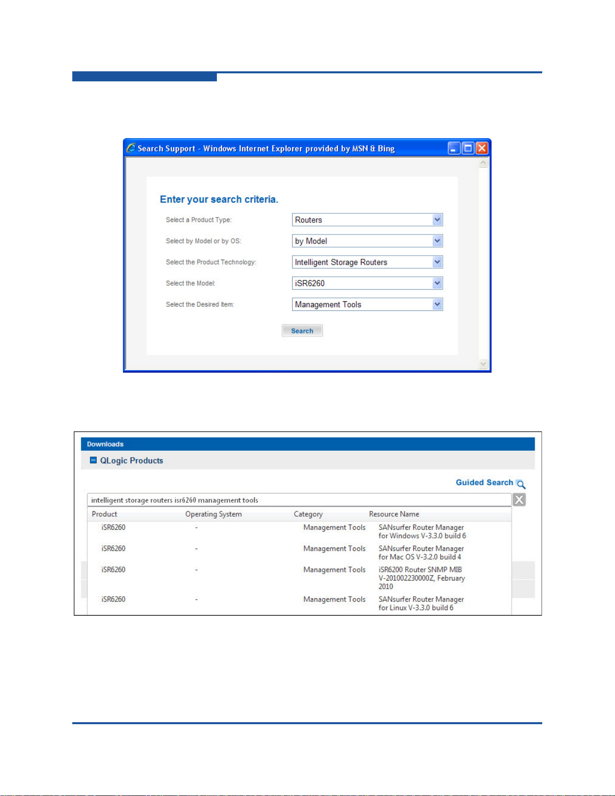
3–Installation
Installing the iSR6200 Router
Figure 3-3 shows an example of the Search Support dialog box in Windows
Internet Explorer.
Figure 3-3. Search Support Dialog Box (Example)
The Downloads page lists the search results; Figure 3-4 shows an example.
Figure 3-4. Guided Search Results
4. Under Resource Name, click the SANsurfer Router Manager for
<operating system> <version> that you want to install.
3-14 ISR651101-00 J
Page 61

5. Under SANsurfer Router Manager for <operating system>, click the
Download link.
6. On the File Download dialog box, click Save.
7. On the Save As dialog box, specify a location on your local machine to store
the installation file, and then click Save.
The installer shows the download progress.
8. Continue with the steps for your operating system, either:
Windows Installation
Linux Installation
Mac OS X Installation
Windows Installation
To install SANsurfer Router Manager on a Windows PC workstation:
1. Follow the download instructions in “Downloading the SANsurfer Router
Manager Installer” on page 3-13.
3–Installation
Installing the iSR6200 Router
2. Close all programs that are currently running.
3. On the Download Complete dialog box, click Run.
4. If your Internet browser displays a security warning, you can safely bypass
the warning.
5. Follow the prompts in the SANsurfer iSCSI-FC Router Manager installation
wizard.
Linux Installation
To install SANsurfer Router Manager on a Linux workstation:
1. Follow the download instructions in “Downloading the SANsurfer Router
Manager Installer” on page 3-13.
2. On the Download Complete dialog box, click Open.
3. Double-click the .bin file to start the installation wizard.
4. Follow the prompts in the SANsurfer iSCSI-FC Router Manager installation
wizard.
Mac OS X Installation
To install SANsurfer Router Manager on a Mac OS X workstation:
1. Follow the download instructions in “Downloading the SANsurfer Router
Manager Installer” on page 3-13.
2. On the Download Complete dialog box, click Open.
ISR651101-00 J 3-15
Page 62

3–Installation
Installing the iSR6200 Router
3. Double-click the install.app icon to start the installation wizard.
4. Follow the prompts in the SANsurfer iSCSI-FC Router Manager installation
wizard.
Starting SANsurfer Router Manager
To start SANsurfer Router Manager, use the applicable method:
For Windows, either double-click the SANsurfer Router Manager desktop
shortcut, or click Start, point to All Programs, point to QLogic
Management Suite, and then click SANsurfer Router Manager , depending
on how you installed the SANsurfer Router Manager utility.
From a Windows command line, issue the following command:
<install_directory>SANsurferRouterManager.exe
From a Linux command prompt, issue the following command:
<install_directory>./SANsurferRouterManager
Configuring the Router
You can configure the router using either SANsurfer Router Manager or the CLI.
In SANsurfer Router Manager, configure router ports by selecting a Fibre Channel
or iSCSI port in the left pane (tree pane), and then completing the Information and
Advanced Configuration pages for that port in the right pane. For details, see the
iSR6200 Router Manager User’s Guide, “FC Ports” and “iSCSI Ports” sections.
To configure the router using the command line interface:
1. Open a command window according to the type of workstation and
connection:
Ethernet (all platforms): Open a Telnet session with the default router
IP address and log into the router with the default account name
(guest) and password (password):
telnet 10.0.0.1
username: guest
password: ********
Serial, Windows: Open the HyperTerminal application on a Windows
platform as follows:
a. From the Windows Start menu, click Programs, point to
Accessories, point to Communications, and then click
HyperTerminal.
b. Select the connection you created earlier, and then click OK.
3-16 ISR651101-00 J
Page 63

3–Installation
Installing New Firmware
Serial, Linux: Open a command window and enter the following
command:
minicom
2. Open an admin session, select a blade (1 or 2), and then enter the
commands to set up both iSCSI ports and the management interface. (See
the iSR6200 Command Line Interface (CLI) User’s Guide for command
descriptions.)
iSR6200 #> admin start
Password : ******
iSR6200 (admin) #> set mgmt
………………………
iSR6200 (admin) #> set iscsi 1
………………………
iSR6200 (admin) #> set iscsi 2
………………………
Connecting Cable Devices to the Router
Connect cables to the SFP transceivers and their corresponding devices. Devices
can have SFP (or small form factor, SFF) transceivers or GBICs. Choose the fiber
optic cable with the connector combination that matches the device being
connected to the router:
LC-type duplex fiber optic cable connectors are designed for SFP
transceivers.
SC-type connectors are designed for GBICs.
OM-3 connectors are designed for 10Gb ports.
Installing New Firmware
The router comes with the current firmware installed. You can upgrade the
firmware from the management workstation when new firmware becomes
available.
To locate and download new firmware:
1. Go to the QLogic Downloads and Documentation page located here:
http://driverdownloads.qlogic.com
2. Under QLogic Products, type router firmware in the search box.
(Alternatively, you can click the Guided Search link to obtain assistance in
locating the firmware to download.)
ISR651101-00 J 3-17
Page 64

3–Installation
NOTE
Installing New Firmware
3. In the results box under Resource Name, click the router firmware that you
want to install, and then download the file.
You can use either SANsurfer Router Manager or the CLI to install new firmware,
as shown in the following sections.
Installing new firmware disrupts the router blade connectivity because you
must reboot the router blade to activate the new firmware.
Using SANsurfer Router Manager to Install Firmware
SANsurfer Router Manager provides the FW Update Wizard with the steps
required to update the iSR6200 firmware on selected iSR6200 router blades.
To install firmware using SANsurfer Router Manager:
1. On the File menu, click FW Update Wizard.
2. On the Router Selection dialog box, click the router blade to update its
firmware, and then click Next.
3. On the Firmware File Selection dialog box, locate and select the firmware
image file, and then click Next.
4. On the Confirm Changes dialog box, review the firmware status, and then
click Next to confirm the changes.
5. On the Firmware Update Status dialog box, respond to the message
prompts, and then click Next.
6. On the final dialog box, reboot to finish the firmware update.
Using the CLI to Install Firmware
To use the CLI to install the firmware, transfer the firmware image file from a
workstation to the router. Then use the CLI image unpack command to install
the new firmware image.
To install firmware in the CLI:
1. At the workstation prompt, use the ftp command to go to the location on
the router where you want to transfer the firmware image. For example:
C:\fwImage>ftp 172.17.137.190
Connected to 172.17.137.190.
220 (none) FTP server (GNU inetutils 1.4.2) ready.
3-18 ISR651101-00 J
Page 65

3–Installation
Installing New Firmware
2. Enter your user name and password. For example:
User (172.17.137.190:(none)): ftp
331 Guest login ok, type your name as password.
Password: ftp
230 Guest login ok, access restrictions apply.
3. At the ftp prompt, type bin to set binary mode. For example:
ftp> bin
200 Type set to I.
4. Use the put command to transfer the firmware image file from the
workstation to the router. For example:
ftp> put isr-6200-3_0_0_5.bin
200 PORT command successful.
150 Opening BINARY mode data connection for
'isr-6200-3_0_0_5.bin'.
226 Transfer complete.
ftp: 4822816 bytes sent in 0.41Seconds 11878.86Kbytes/sec.
5. Enter quit.
The firmware image has been transferred to the router.
6. At a Telnet prompt, log on to the router as an administrator.
7. Select one of the blades.
8. Enter the following command from the router, where x indicates the
firmware image name:
image unpack isr-62xx-x_x_x_x.bin
The following message appears:
Unpack Completed. Please reboot the system for FW to take
effect.
9. Enter reboot.
The following message appears:
Are you sure you want to reboot the System (y/n):
10. To reboot the system, type y.
11. If a second blade is installed, repeat this procedure.
ISR651101-00 J 3-19
Page 66

3–Installation
Installing New Firmware
3-20 ISR651101-00 J
Page 67

4 Configuration
This chapter describes how to configure the iSR6200 router to support virtual port
groups (VPGroups or VPGs) and LUN mapping.
Some storage arrays limit the number of LUNs exposed to a host to 256 LUNs.
Each iSR6200 router blade supports up to four VPGs, making it possible for these
storage arrays to present up to 1,024 LUNs per blade.
When configuring VPGs on the iSR6200 router, follow these guidelines:
All Fibre Channel (FC) virtual ports from a single VPG must be part of only
one logical host on the storage array.
Fibre Channel ports from different VPGs must not be part of the same logical
host on the storage array.
A specific LUN can be presented to one and only one VPG. It can be
presented to other Fibre Channel hosts, but only one VPG on a specific
iSR6200 router (chassis).
The following sections describe how to configure VPGs and the Fibre Channel
arrays connected to them:
“Enabling Virtual Port Groups” on page 4-2
“Zoning Virtual Port Groups on the SAN” on page 4-9
“Configuring Fibre Channel Array Hosts and LUN Assignments” on
page 4-12
“Connecting iSCSI Hosts to the iSR6200” on page 4-16
“Controlling per-Host LUN Access on the iSR6200” on page 4-22
ISR651101-00 J 4-1
Page 68

4–Configuration
Enabling Virtual Port Groups
Enabling Virtual Port Groups
Each iSR6250 router blade has one virtual port group (VPG) enabled by default,
which gives iSCSI hosts access to 256 LUNs. You can enable and configure
additional VPGs to give iSCSI hosts access to more than 256 distinct LUNS from
a specific Fibre Channel target array.
Each blade has VPG 1 enabled by default; VPG 1 is the primary virtual port group
and cannot be disabled. Enabling additional virtual port groups creates additional
logical Fibre Channel adapter initiator ports on the fabric. These ports act as
separate Fibre Channel adapter host ports, and additional 256 LUNs can be
presented to each of them. With all four VPGs enabled, a single iSR6250 blade
can access up to1,024 LUNs from a single target world wide port number
(WWPN).
You can view Virtual Port Group information using the show vpgroups command
in the CLI, as shown in the following example.
iSR6200 <1> (admin) #> show vpgroups
VpGroup Information
---------------------
Index 1
VpGroup Name VPGROUP_1
Status Enabled
WWPNs 21:00:00:c0:dd:13:16:f8
21:00:00:c0:dd:13:16:f9
Index 2
VpGroup Name VPGROUP_2
Status Disabled
WWPNs N/A
Index 3
VpGroup Name VPGROUP_3
Status Disabled
WWPNs N/A
Index 4
VpGroup Name VPGROUP_4
Status Disabled
WWPNs N/A
4-2 ISR651101-00 J
Page 69

4–Configuration
Enabling Virtual Port Groups
Using SANsurfer Router Manager, select one of the VP Group nodes in the left
pane to view that VP Group’s information in the right pane, as shown in
Figure 4-1.
Figure 4-1. SANsurfer Router Manager VPGroup
You can enable or disable virtual port groups on your blade using either
SANsurfer Router Manager or the CLI.
To enable or disable a VPGroup using SANsurfer Router Manager:
1. In the system tree pane on the left, click the VP Group.
The right panel shows information about the selected VP Group.
ISR651101-00 J 4-3
Page 70
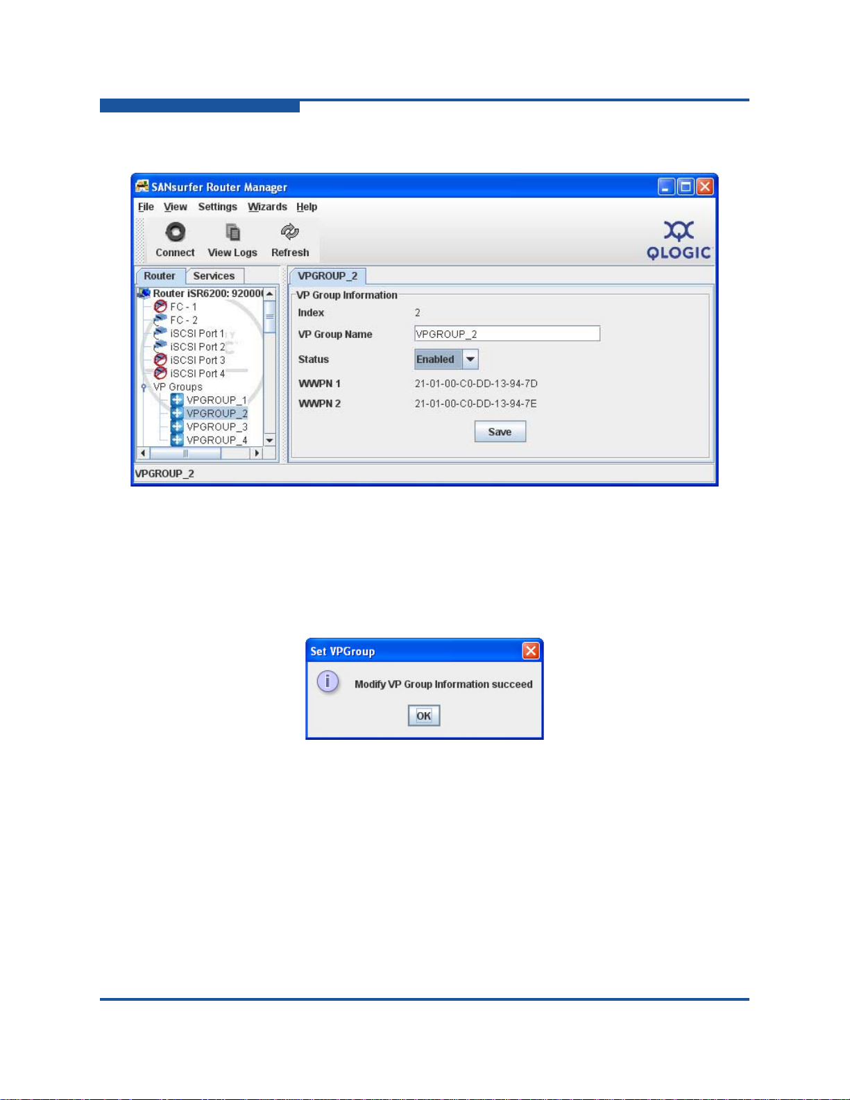
4–Configuration
Enabling Virtual Port Groups
2. In the Status list, select Enabled or Disabled (see Figure 4-2).
Figure 4-2. Chassis Information for Selected VPGROUP
3. Click Save.
4. In the System Check dialog box, type the system password, and then click
OK.
The Set VPGroup message box opens, as shown in Figure 4-3.
Figure 4-3. Set VPGroup Message Box
5. Click OK to close the message box.
4-4 ISR651101-00 J
Page 71

4–Configuration
Enabling Virtual Port Groups
To enable or disable a VPGroup using the CLI:
The following example shows how to enable VPGroups 2 and 3 by issuing the CLI
set vpgroups command.
iSR6200 <1> (admin) #> set vpgroups
The following wizard will query for attributes before persisting
and activating the updated mapping in the system configuration.
If you wish to terminate this wizard before reaching the end of the list
press 'q' or 'Q' and the ENTER key to do so.
Configuring VpGroup: 1
------------------------ Status (0=Enable, 1=Disable) [Enabled ]
VpGroup Name (Max = 64 characters) [VPGROUP_1 ]
All attribute values for VpGroup 1 that have been changed will now be saved.
Configuring VpGroup: 2
------------------------ Status (0=Enable, 1=Disable) [Disabled ] 0
VpGroup Name (Max = 64 characters) [VPGROUP_2 ]
All attribute values for VpGroup 2 that have been changed will now be saved.
Configuring VpGroup: 3
------------------------ Status (0=Enable, 1=Disable) [Disabled ] 0
VpGroup Name (Max = 64 characters) [VPGROUP_3 ]
All attribute values for VpGroup 3 that have been changed will now be saved.
Configuring VpGroup: 4
------------------------ Status (0=Enable, 1=Disable) [Disabled ]
All attribute values for VpGroup 4 that have been changed will now be saved.
ISR651101-00 J 4-5
Page 72

4–Configuration
Enabling Virtual Port Groups
The following example shows CLI command output using an iSR6200 blade with
three virtual port groups enabled. You can view information about the virtual port
groups configured on your iSR6200 by issuing the show vpgroups command.
iSR6200 <1> (admin) #> show vpgroups
VpGroup Information
---------------------
Index 1
VpGroup Name VPGROUP_1
Status Enabled
WWPNs 21:00:00:c0:dd:13:16:f8
21:00:00:c0:dd:13:16:f9
Index 2
VpGroup Name VPGROUP_2
Status Enabled
WWPNs 21:01:00:c0:dd:13:16:f8
21:01:00:c0:dd:13:16:f9
Index 3
VpGroup Name VPGROUP_3
Status Enabled
WWPNs 21:02:00:c0:dd:13:16:f8
21:02:00:c0:dd:13:16:f9
Index 4
VpGroup Name VPGROUP_4
Status Disabled
WWPNs N/A
In the preceding examples, the second byte from the left (in bold text) denotes the
virtual port group ID, and the right-most byte (in italic text) denotes the physical
Fibre Channel port. In these examples VPGs 1 through 3 have corresponding
virtual ports with 00, 01, and 02 presented out of physical FC ports 0 and 1, with
WWPNs ending in f8 and f9, respectively.
4-6 ISR651101-00 J
Page 73

4–Configuration
Enabling Virtual Port Groups
The following example shows the information grouped by physical Fibre Channel
port.
iSR6200 <1> (admin) #> show fc
FC Port Information
-------------------- FC Port 1
Port Status Enabled
Link Status Up
Current Link Rate 4Gb
Programmed Link Rate Auto
WWNN 20:00:00:c0:dd:13:16:f8 (VPGROUP_1)
WWPN 21:00:00:c0:dd:13:16:f8 (VPGROUP_1)
Port ID 0a-04-00 (VPGROUP_1)
WWNN 20:01:00:c0:dd:13:16:f8 (VPGROUP_2)
WWPN 21:01:00:c0:dd:13:16:f8 (VPGROUP_2)
Port ID 0a-04-01 (VPGROUP_2)
WWNN 20:02:00:c0:dd:13:16:f8 (VPGROUP_3)
WWPN 21:02:00:c0:dd:13:16:f8 (VPGROUP_3)
Port ID 0a-04-02 (VPGROUP_3)
Firmware Revision No. 4.05.00
Frame Size 2048
Execution Throttle 32768
Connection Mode Point-to-Point
Programmed Connection Option Loop Preferred
SFP Type 8Gb
FC Port 2
Port Status Enabled
Link Status Up
Current Link Rate 4Gb
Programmed Link Rate Auto
WWNN 20:00:00:c0:dd:13:16:f9 (VPGROUP_1)
WWPN 21:00:00:c0:dd:13:16:f9 (VPGROUP_1)
Port ID 0a-05-00 (VPGROUP_1)
WWNN 20:01:00:c0:dd:13:16:f9 (VPGROUP_2)
WWPN 21:01:00:c0:dd:13:16:f9 (VPGROUP_2)
Port ID 0a-05-01 (VPGROUP_2)
WWNN 20:02:00:c0:dd:13:16:f9 (VPGROUP_3)
WWPN 21:02:00:c0:dd:13:16:f9 (VPGROUP_3)
ISR651101-00 J 4-7
Page 74

4–Configuration
NOTE
Enabling Virtual Port Groups
Port ID 0a-05-02 (VPGROUP_3)
Firmware Revision No. 4.05.00
Frame Size 2048
Execution Throttle 32768
Connection Mode Point-to-Point
Programmed Connection Option Loop Preferred
SFP Type 8Gb
iSR6200 <1> (admin) #>
Notice also the VP index in the second byte from the left, and the Fibre Channel
port indicator in the right-most byte.
To see this information using SANsurfer Router Manager, select one of the Fibre
Channel ports, as shown in Figure 4-4.
Figure 4-4. FC Port Information Page
For more details on using the utility, use the SANsurfer Router Manager
Help or refer to the iSR6200 Router Manager User’s Guide.
4-8 ISR651101-00 J
Page 75

Zoning Virtual Port Groups on the SAN
Zoning Virtual Port Groups on the SAN
When zoning the iSR6200 virtual port group WWPNs to a Fibre Channel array,
you must ensure all WWPNs of a virtual port group are zoned to any single Fibre
Channel target WWPN. Figure 4-5 shows the proper zoning for a single blade
iSR6200 with three VP groups enabled using a single Fibre Channel switch.
4–Configuration
iSR6200
Blade 1
21:00:00:c0:dd:13:16:f8
21:01:00:c0:dd:13:16:f8
FC1
21:02:00:c0:dd:13:16:f8
21:00:00:c0:dd:13:16:f9
21:01:00:c0:dd:13:16:f9
FC2
21:02:00:c0:dd:13:16:f9
Zone 6200 FC_One
21:00:00:c0:dd:13:16:f8
21:01:00:c0:dd:13:16:f8
21:02:00:c0:dd:13:16:f8
A1
B0
SAN A
SAN A
Zone 6200 FC_Two
21:00:00:c0:dd:13:16:f9
21:00:00:c0:dd:13:16:f9
21:01:00:c0:dd:13:16:f9
21:01:00:c0:dd:13:16:f9
21:02:00:c0:dd:13:16:f9
21:02:00:c0:dd:13:16:f9
A0
B1
FC Target Array
Controller A
FC1 A0
A1
FC2
Controller B
FC1
B0
B1
FC2
Figure 4-5. Single Blade, Single Fibre Channel Switch
ISR651101-00 J 4-9
Page 76

4–Configuration
iSR6200
FC Target Array
SAN B
Blade 1
21:00:00:c0:dd:13:16:f8
21:01:00:c0:dd:13:16:f8
21:02:00:c0:dd:13:16:f8
FC1
FC2
21:00:00:c0:dd:13:16:f9
21:01:00:c0:dd:13:16:f9
21:02:00:c0:dd:13:16:f9
FC1 A0
A1
B0
B1
Controller A
Controller B
FC2
FC1
FC2
6200 FC_One A
SAN A
A0
B1
21:00:00:c0:dd:13:16:f8
21:01:00:c0:dd:13:16:f8
21:02:00:c0:dd:13:16:f8
6200 FC_Two B
A1
B0
21:00:00:c0:dd:13:16:f9
21:01:00:c0:dd:13:16:f9
21:02:00:c0:dd:13:16:f9
Zoning Virtual Port Groups on the SAN
When connecting a single-bladed iSR6200 to two independent SANs, connect
one Fibre Channel port from your iSR6200 blade to each SAN (see Figure 4-6).
This topology ensures Fibre Channel link-level and switch-level failure protection.
Figure 4-6. Single Blade, Dual Fibre Channel Switch
4-10 ISR651101-00 J
Page 77

Zoning Virtual Port Groups on the SAN
SAN A
iSR6200
FC Target Array
SAN B
Blade 1
Blade 2
21:00:00:c0:dd:13:16:f8
21:01:00:c0:dd:13:16:f8
21:02:00:c0:dd:13:16:f8
FC1
FC2
FC1
FC2
21:00:00:c0:dd:13:16:f9
21:01:00:c0:dd:13:16:f9
21:02:00:c0:dd:13:16:f9
21:00:00:c0:dd:13:17:02
21:01:00:c0:dd:13:17:02
21:02:00:c0:dd:13:17:02
21:00:00:c0:dd:13:17:03
21:01:00:c0:dd:13:17:03
21:02:00:c0:dd:13:17:03
FC1 A0
A1
B0
B1
Controller A
Controller B
FC2
FC1
FC2
A0
B1
21:00:00:c0:dd:13:16:f8
21:01:00:c0:dd:13:16:f8
21:02:00:c0:dd:13:16:f8
A0
B1
21:00:00:c0:dd:13:17:02
21:01:00:c0:dd:13:17:02
21:02:00:c0:dd:13:17:02
A1
B0
A1
B0
Zone 6200 Blade 1 A Zone 6200 Blade 2 A
Zone 6200 Blade 1 B Zone 6200 Blade 2 B
21:00:00:c0:dd:13:16:f9
21:01:00:c0:dd:13:16:f9
21:02:00:c0:dd:13:16:f9
21:00:00:c0:dd:13:17:03
21:01:00:c0:dd:13:17:03
21:02:00:c0:dd:13:17:03
When connecting a dual-blade iSR6200 for high availability, connect one Fibre
Channel port from each blade to each of your fabrics (see Figure 4-7). This
topology provides link-level, switch-level, and blade-level failure protection. To
make this effective, you must connect the iSCSI hosts to both iSR6200 blades.
For details, see “Connecting iSCSI Hosts to the iSR6200” on page 4-16.
4–Configuration
ISR651101-00 J 4-11
Figure 4-7. High-Availability, Dual Blades, Dual Fibre Channel Switches
Page 78

4–Configuration
Configuring Fibre Channel Array Hosts and LUN Assignments
Configuring Fibre Channel Array Hosts and LUN Assignments
When configuring Fibre Channel array hosts, you must treat each iSR6200 virtual
port group (VPG) as its own unique Fibre Channel host within the virtualized
storage array. This means if you have only one VPG enabled, the iSR6200 will
have only one host entity. If you enable two more VPGs,
three separate host entities to your storage array.
Each host entity must contain WWPNs from the same VPG. Figure 4-8 shows a
correct configuration.
the iSR6200 presents
Figure 4-8. Correctly Configured Storage Array Using Virtual Port Groups
Do not simply group all Fibre Channel ports from the iSR6200 router into a single
host entity. Doing so defeats the purpose of virtual port groups, limiting you to 256
LUNs. It will also cause problems when you later try to restore access to
additional LUNS.
4-12 ISR651101-00 J
Page 79

4–Configuration
Configuring Fibre Channel Array Hosts and LUN Assignments
Figure 4-9 illustrates this incorrect configuration.
Figure 4-9. Incorrectly Configuring All Groups to One Host Entity
Figure 4-10 shows an incorrect assignment of virtual port group WWPNs. Notice
that host entity 1 and host entity 2 both contain ports from more than one
VPGroup.
Figure 4-10. Incorrectly Assigning VPG WWPNs
ISR651101-00 J 4-13
Page 80

4–Configuration
Configuring Fibre Channel Array Hosts and LUN Assignments
If you are using two blades in a high availability configuration, assign each VPG
from the second 6200 blade in the same chassis to the same host entity as VPG
from blade 1, as shown in Figure 4-11.
Figure 4-11. Correct VPG Assignments for High Availability Configuration
Do not put VPG ports in host entities with other Fibre Channel hosts.
4-14 ISR651101-00 J
Page 81

4–Configuration
iSR6200
Storage Array
Blade 1
21:00:00:c0:dd:13:16:f8
21:01:00:c0:dd:13:16:f8
21:02:00:c0:dd:13:16:f8
21:00:00:c0:dd:13:16:f8
21:00:00:c0:dd:13:16:f9
FC1
FC2
Host Entities
Host Entity 0
21:01:00:c0:dd:13:16:f8
21:01:00:c0:dd:13:16:f9
Host Entity 1
21:02:00:c0:dd:13:16:f8
21:02:00:c0:dd:13:16:f9
Host Entity 2
21:00:00:c0:dd:13:16:f9
21:01:00:c0:dd:13:16:f9
21:02:00:c0:dd:13:16:f9
LUN 1
LUN 2
LUN 3
LUN 4
Configuring Fibre Channel Array Hosts and LUN Assignments
When assigning LUNs to your VPG host entities, do not assign the same LUN to
two VPG host entities. Figure 4-12 shows a valid LUN presentation. Each LUN is
presented to only one VPG. Any of these LUNs can be presented to any number
of other Fibre Channel hosts on the array, but can be presented to one and only
one VPG of the iSR6200.
Figure 4-12. Correctly Assigning LUNs to Your VPG Host Entities
ISR651101-00 J 4-15
Page 82

4–Configuration
iSR6200
Storage Array
Blade 1
21:00:00:c0:dd:13:16:44
21:00:00:c0:dd:13:16:45
FC1
FC2
Host Entities
Host Entity 0
21:01:00:c0:dd:13:16:44
21:01:00:c0:dd:13:16:45
Host Entity 1
21:02:00:c0:dd:13:16:44
21:02:00:c0:dd:13:16:45
Host Entity 2
21:03:00:c0:dd:13:16:44
21:03:00:c0:dd:13:16:45
Host Entity 3
LUN 1
LUN 2
LUN 3
LUN 4
LUN 5
21:00:00:c0:dd:13:16:44
21:01:00:c0:dd:13:16:44
21:02:00:c0:dd:13:16:44
21:03:00:c0:dd:13:16:44
21:00:00:c0:dd:13:16:45
21:01:00:c0:dd:13:16:45
21:02:00:c0:dd:13:16:45
21:03:00:c0:dd:13:16:45
Connecting iSCSI Hosts to the iSR6200
Figure 4-13 shows presenting LUN 3 incorrectly. If an iSCSI host logged into both
VPG0 and VPG1, it would have access to LUN 3 through two virtual port groups.
This is invalid and will lead to serious problems.
Figure 4-13. Incorrectly Presenting LUN 3
Presenting the LUN at different LUN indexes for each VP will confuse the iSCSI
host MPIO software because it will see the same LUN WWLUNID at two different
indexes. This can cause the multipath I/O (MPIO) driver to panic and show a blue
screen. Without an MPIO driver, the system could corrupt data on the LUN,
without crashing—a situation you want to avoid.
Connecting iSCSI Hosts to the iSR6200
Upon logging into a Fibre Channel target WWPN, an iSR6200 blade presents an
iSCSI target to which iSCSI initiators can connect. This target is defined by its
iSCSI qualified name (IQN) string. To correctly connect iSCSI initiators to Fibre
4-16 ISR651101-00 J
Channel targets through the iSR6200, it is important to understand the
composition of the iSCSI target IQN string.
Page 83

4–Configuration
1
2 3
4
5
6
Connecting iSCSI Hosts to the iSR6200
The following example shows the anatomy of a sample IQN string from an
iSR6200 router:
iqn.2004-08.com.qlogic:iSR6200.0834e00019.b1.01.20030020c2075970
1. Vendor name and registration date
2. Product Name
3. iSR6200 Chassis Serial Number
4. Blade (b1 or b2)
5. VPGroup (01 through 04)
6. Fibre Channel target WWPN
Notice that the IQN string does not contain any information about the physical
iSR6200 iSCSI port. iSCSI load balancing and failover are handled by the iSCSI
host and not the iSR6200. Also notice that the IQN string does not contain any
information indicating which physical iSR6200 Fibre Channel port the target
device is connected.
You can view the complete list of IQN strings that your iSR6200 is presenting with
the show presented_targets command in the CLI. For example:
iSR6200 <1> (admin) #> show presented_targets
Presented Target Information
------------------------------
iSCSI Presented Targets
------------------------ Name iqn.2004-08.com.qlogic:iSR6200.0834e00019.r1.00.20030020c2075970
Alias
<MAPS TO>
WWNN 10:00:00:20:c2:07:59:70
WWPN 20:03:00:20:c2:07:59:70
Name iqn.2004-08.com.qlogic:iSR6200.0834e00019.r1.00.21040020c2075970
Alias
<MAPS TO>
WWNN 10:00:00:20:c2:07:59:70
WWPN 21:04:00:20:c2:07:59:70
ISR651101-00 J 4-17
Page 84

4–Configuration
Connecting iSCSI Hosts to the iSR6200
To view presented target information using SANsurfer Router Manager, expand
the iSCSI Presented Targets node in the left pane, and then select the device, as
shown in Figure 4-14.
Figure 4-14. Selecting the iSCSI Presented Targets in SANsurfer Router Manager
4-18 ISR651101-00 J
Page 85

4–Configuration
Connecting iSCSI Hosts to the iSR6200
Enabling additional VP Groups creates multiple IQN strings for the same Fibre
Channel target WWPN. The following example shows two Fibre Channel target
WWPNs and three VP groups, resulting in six presented iSCSI qualified names.
For information about how to enable and configure additional VP Groups, see
“Enabling Virtual Port Groups” on page 4-2.
iSR6200 <1> (admin) #> show targets
Target Information
--------------------
WWNN 10:00:00:20:c2:07:59:70
WWPN 20:03:00:20:c2:07:59:70
Port ID 0a-02-00
State Online
WWNN 10:00:00:20:c2:07:59:70
WWPN 21:04:00:20:c2:07:59:70
Port ID 0a-03-00
State Online
iSR6200 <1> #> show vpgroups
VpGroup Information
---------------------
Index 1
VpGroup Name VPGROUP_1
Status Enabled
WWPNs 21:00:00:c0:dd:13:16:f8
21:00:00:c0:dd:13:16:f9
Index 2
VpGroup Name VPGROUP_2
Status Enabled
WWPNs 21:01:00:c0:dd:13:16:f8
21:01:00:c0:dd:13:16:f9
Index 3
VpGroup Name VPGROUP_3
Status Enabled
WWPNs 21:02:00:c0:dd:13:16:f8
21:02:00:c0:dd:13:16:f9
Index 4
ISR651101-00 J 4-19
Page 86

4–Configuration
Connecting iSCSI Hosts to the iSR6200
VpGroup Name VPGROUP_4
Status Disabled
WWPNs N/A
iSR6200 <1> (admin) #> show presented_targets
Presented Target Information
------------------------------
iSCSI Presented Targets
------------------------ Name iqn.2004-08.com.qlogic:iSR6200.0834e00019.r1.01.20030020c2075970
Alias
<MAPS TO>
WWNN 10:00:00:20:c2:07:59:70
WWPN 20:03:00:20:c2:07:59:70
Name iqn.2004-08.com.qlogic:iSR6200.0834e00019.r1.01.21040020c2075970
Alias
<MAPS TO>
WWNN 10:00:00:20:c2:07:59:70
WWPN 21:04:00:20:c2:07:59:70
Name iqn.2004-08.com.qlogic:iSR6200.0834e00019.r1.02.20030020c2075970
Alias
<MAPS TO>
WWNN 10:00:00:20:c2:07:59:70
WWPN 20:03:00:20:c2:07:59:70
Name iqn.2004-08.com.qlogic:iSR6200.0834e00019.r1.02.21040020c2075970
Alias
<MAPS TO>
WWNN 10:00:00:20:c2:07:59:70
WWPN 21:04:00:20:c2:07:59:70
Name iqn.2004-08.com.qlogic:iSR6200.0834e00019.r1.03.20030020c2075970
Alias
<MAPS TO>
WWNN 10:00:00:20:c2:07:59:70
WWPN 20:03:00:20:c2:07:59:70
Name iqn.2004-08.com.qlogic:iSR6200.0834e00019.r1.03.21040020c2075970
4-20 ISR651101-00 J
Page 87

Alias
iSR6200
iSCSI Host
Storage Array
Blade 1
21:00:00:c0:dd:13:16:f8
21:01:00:c0:dd:13:16:f8
21:02:00:c0:dd:13:16:f8
21:00:00:c0:dd:13:16:f8
21:00:00:c0:dd:13:16:f9
FC1
FC2
Host Entities
Host Entity 0
21:01:00:c0:dd:13:16:f8
21:01:00:c0:dd:13:16:f9
Host Entity 1
21:02:00:c0:dd:13:16:f8
21:02:00:c0:dd:13:16:f9
Host Entity 2
21:00:00:c0:dd:13:16:f9
21:01:00:c0:dd:13:16:f9
21:02:00:c0:dd:13:16:f9
LUN 1
LUN 2
LUN 1
LUN 2
LUN 3
LUN 4
20:03:00:20:c2:07:59:70
SAN
LAN
iqn.2004-08.com:isr6200.0834e00019.r1.00.20030020c2075970
iqn.2004-08.com:isr6200.0834e00019.r1.00.20030020c2075970
iqn.2004-08.com:isr6200.0834e00019.r1.00.20030020c2075970
<MAPS TO>
WWNN 10:00:00:20:c2:07:59:70
WWPN 21:04:00:20:c2:07:59:70
iSCSI host LUN access is determined by the specific iSCSI target to which the
host connects. Pay special attention to the VPG index portion of the IQN string; it
is critical to understanding which group of storage array LUNs the host will
access.
In Figure 4-15, the iSCSI host has logged into iSCSI target for VPG0. The host
can access VPG0 LUNs 1 and 2 from the storage array.
4–Configuration
Connecting iSCSI Hosts to the iSR6200
Figure 4-15. Host Access to LUNs on Storage Array
ISR651101-00 J 4-21
Page 88

4–Configuration
iSR6200
iSCSI Host
Storage Array
Blade 1
21:00:00:c0:dd:13:16:f8
21:01:00:c0:dd:13:16:f8
21:02:00:c0:dd:13:16:f8
21:00:00:c0:dd:13:16:f8
21:00:00:c0:dd:13:16:f9
FC1
FC2
Host Entities
Host Entity 0
21:01:00:c0:dd:13:16:f8
21:01:00:c0:dd:13:16:f9
Host Entity 1
21:02:00:c0:dd:13:16:f8
21:02:00:c0:dd:13:16:f9
Host Entity 2
21:00:00:c0:dd:13:16:f9
21:01:00:c0:dd:13:16:f9
21:02:00:c0:dd:13:16:f9
LUN 1
LUN 2
LUN 3
LUN 3
LUN 4
20:03:00:20:c2:07:59:70
SAN
LAN
iqn.2004-08.com:isr6200.0834e00019.r1.00.20030020c2075970
iqn.2004-08.com:isr6200.0834e00019.r1.00.20030020c2075970
iqn.2004-08.com:isr6200.0834e00019.r1.00.20030020c2075970
iSR6200
iSCSI Host
Storage Array
Blade 1
21:00:00:c0:dd:13:16:f8
21:01:00:c0:dd:13:16:f8
21:02:00:c0:dd:13:16:f8
21:00:00:c0:dd:13:16:f8
21:00:00:c0:dd:13:16:f9
FC1
FC2
Host Entities
Host Entity 0
21:01:00:c0:dd:13:16:f8
21:01:00:c0:dd:13:16:f9
Host Entity 1
21:02:00:c0:dd:13:16:f8
21:02:00:c0:dd:13:16:f9
Host Entity 2
21:00:00:c0:dd:13:16:f9
21:01:00:c0:dd:13:16:f9
21:02:00:c0:dd:13:16:f9
LUN 1
LUN 2
LUN 3 LUN 4
LUN 3
LUN 4
20:03:00:20:c2:07:59:70
SAN
LAN
iqn.2004-08.com:isr6200.0834e00019.r1.00.20030020c2075970
iqn.2004-08.com:isr6200.0834e00019.r1.00.20030020c2075970
iqn.2004-08.com:isr6200.0834e00019.r1.00.20030020c2075970
Controlling per-Host LUN Access on the iSR6200
In Figure 4-16, the iSCSI host has logged into iSCSI target for VPG1. The host
can access VPG1 LUN #3 from the storage array.
Figure 4-16. iSCSI Host Logged into iSCSI Target for VPG0
In Figure 4-17, the iSCSI host has logged into iSCSI targets for both VPG1 and
VPG2. The host can access both VPG1 and VPG2 LUNs 3 and 4.
Controlling per-Host LUN Access on the iSR6200
4-22 ISR651101-00 J
Figure 4-17. iSCSI Host Logged into iSCSI Target for VPG1
The iSR6200 allows multiple iSCSI initiators to connect to a single Fibre Channel
target through a specific VPG. Controlling individual LUN access for each iSCSI
host requires LUN mapping devices connected through the iSR6200.
Page 89

4–Configuration
NOTE
Host accessible LUNs
Storage Array
21:00:00:c0:dd:13:16:f8
21:01:00:c0:dd:13:16:f8
21:02:00:c0:dd:13:16:f8
21:00:00:c0:dd:13:16:f8
21:00:00:c0:dd:13:16:f9
iSR6200
Blade 1
FC1
FC2
Host Entities
Host Entity 0
21:01:00:c0:dd:13:16:f8
21:01:00:c0:dd:13:16:f9
Host Entity 1
21:02:00:c0:dd:13:16:f8
21:02:00:c0:dd:13:16:f9
Host Entity 2
21:00:00:c0:dd:13:16:f9
21:01:00:c0:dd:13:16:f9
21:02:00:c0:dd:13:16:f9
LUN 1
LUN 2
LUN 3
LUN 4
LUN 5
LUN 6
iqn.2004-08.com:isr6200.0834e00019.r1.00.20030020c2075970
iqn.2004-08.com:isr6200.0834e00019.r1.00.20030020c2075970
iqn.2004-08.com:isr6200.0834e00019.r1.00.20030020c2075970
Log-In
Controlling per-Host LUN Access on the iSR6200
Before proceeding with this section, be sure you have read and understand
the previous sections of this chapter.
Figure 4-18 shows that even after logging into the VPG0 iSCSI target, the host
cannot access data LUNs on the storage array. To allow the iSCSI host access to
each LUN, you must configure the iSR6200 using either SANsurfer Router
Manager or the CLI.
ISR651101-00 J 4-23
Figure 4-18. Logging into Target Before LUN Mapping
Page 90

4–Configuration
Controlling per-Host LUN Access on the iSR6200
The following example shows how to map the LUN targets with initiators using CLI
commands.
iSR6200 <1> (admin) #> lunmask add
Index Mapped (WWNN,WWPN/iSCSI Name)
----- ------ ----------------------
0 Yes iqn.1991-05.com.microsoft:winhaz38
Please select an Initiator from the list above ('q' to quit): 0
Index (VpGroup Name)
----- --------------
1 VPGROUP_1
2 VPGROUP_2
3 VPGROUP_3
4 VPGROUP_4
Multiple VpGroups are currently 'ENABLED'.
Please select a VpGroup from the list above ('q' to quit): 1
Index (WWNN,WWPN/iSCSI Name)
----- ----------------------
0 50:06:01:60:c1:e0:0d:a2,50:06:01:60:41:e0:0d:a2
1 50:06:01:60:c1:e0:0d:a2,50:06:01:68:41:e0:0d:a2
Please select a Target from the list above ('q' to quit): 0
Index (LUN/VpGroup) Vendor
----- ------------- ------
1 1/VPGROUP_1 DGC
2 2/VPGROUP_1 DGC
3 3/VPGROUP_1 DGC
Please select a LUN to present to the initiator ('q' to quit): 1
All attribute values that have been changed will now be saved.
4-24 ISR651101-00 J
Page 91

4–Configuration
Host accessible LUNs
Storage Array
21:00:00:c0:dd:13:16:f8
21:01:00:c0:dd:13:16:f8
21:02:00:c0:dd:13:16:f8
21:00:00:c0:dd:13:16:f8
21:00:00:c0:dd:13:16:f9
iSR6200
Blade 1
FC1
FC2
Host Entities
Host Entity 0
21:01:00:c0:dd:13:16:f8
21:01:00:c0:dd:13:16:f9
Host Entity 1
21:02:00:c0:dd:13:16:f8
21:02:00:c0:dd:13:16:f9
Host Entity 2
21:00:00:c0:dd:13:16:f9
21:01:00:c0:dd:13:16:f9
21:02:00:c0:dd:13:16:f9
LUN 1
LUN 2
LUN 3
LUN 4
LUN 5
LUN 6
iqn.2004-08.com:isr6200.0834e00019.r1.00.20030020c2075970
iqn.2004-08.com:isr6200.0834e00019.r1.00.20030020c2075970
iqn.2004-08.com:isr6200.0834e00019.r1.00.20030020c2075970
Log-In
LUN 1
Controlling per-Host LUN Access on the iSR6200
Figure 4-19 shows the effect of mapping an initiator to LUN 1 using the CLI
commands shown in the preceding example.
Figure 4-19. Logging into Target After Mapping LUN 1
You can accomplish the same LUN mapping using the SANsurfer Router
Manager’s Target Presentation/LUN Mapping Wizard.
To map LUN 1 to an initiator using SANsurfer Router Manager:
1. On the Wizards menu, click Presentation Wizard.
ISR651101-00 J 4-25
The Target Presentation/LUN Mapping Wizard opens.
Page 92
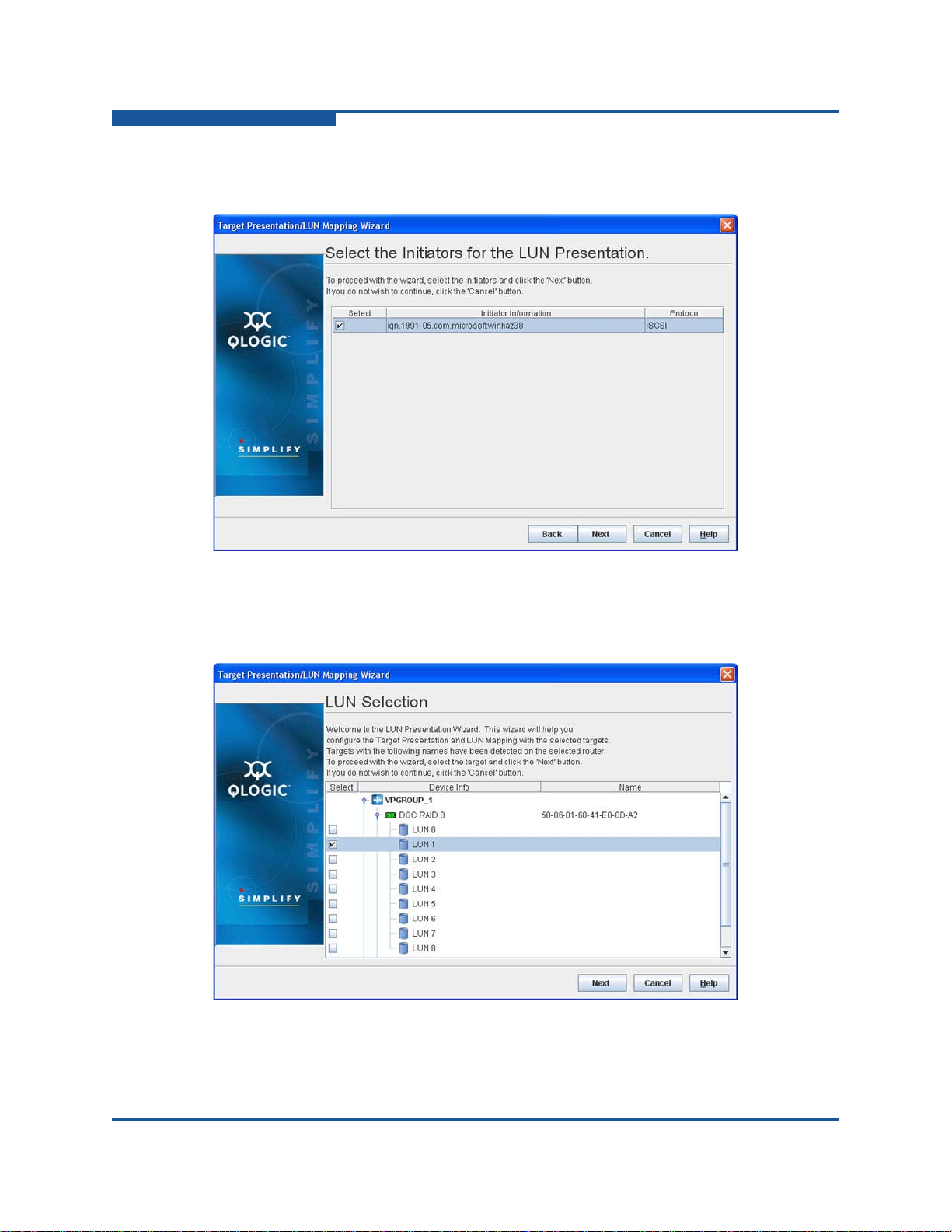
4–Configuration
Controlling per-Host LUN Access on the iSR6200
2. On the Select the Initiators for the LUN Presentation window, select an
initiator as shown in Figure 4-20, and then click Next.
Figure 4-20. Target Presentation/LUN Mapping Wizard—Select the Initiators
3. On the LUN Selection window, select LUN1 as shown in Figure 4-21, and
then click Next.
Figure 4-21. Target Presentation/LUN Mapping Wizard—LUN Selection
4-26 ISR651101-00 J
Page 93

4–Configuration
Controlling per-Host LUN Access on the iSR6200
The LUN Masking Configuration Status window opens, and the Security
Check dialog box prompts you to enter the admin password.
4. In the Security Check dialog box, type the system password (the default is
config), and then click Next.
The LUN Masking Configuration Status window lists the mapping requests,
as shown in Figure 4-22.
Figure 4-22. Target Presentation/LUN Mapping Wizard—LUN Masking
Configuration Status
5. Verify the completion status shown on the LUN Masking Configuration
Status window, and then click Finish to close the wizard.
You can map additional LUNs using either SANsurfer Router Manager or the CLI.
The iSCSI host cannot access mapped LUNs until it logs into the presented target
for the corresponding iSR6200 virtual port group and Fibre Channel target
WWPN.
ISR651101-00 J 4-27
Page 94
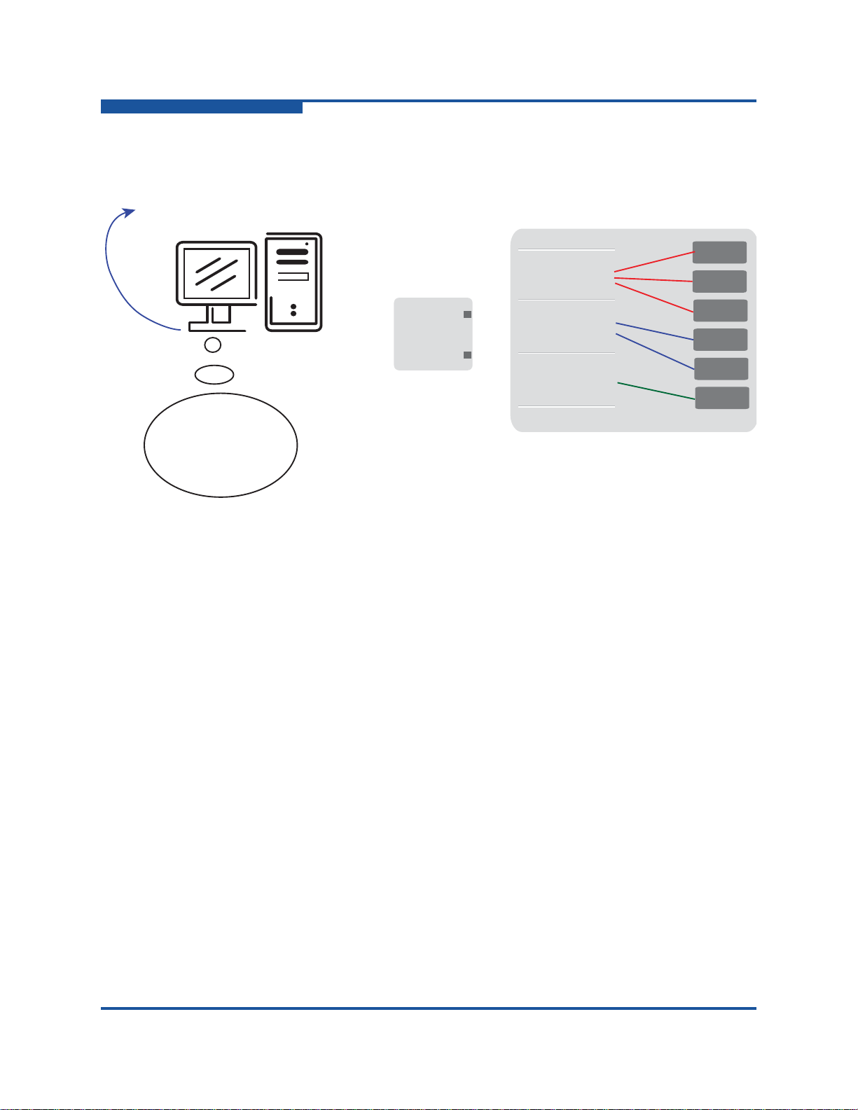
4–Configuration
Host accessible LUNs
Storage Array
21:00:00:c0:dd:13:16:f8
21:01:00:c0:dd:13:16:f8
21:02:00:c0:dd:13:16:f8
21:00:00:c0:dd:13:16:f8
21:00:00:c0:dd:13:16:f9
iSR6200
Blade 1
FC1
FC2
Host Entities
Host Entity 0
21:01:00:c0:dd:13:16:f8
21:01:00:c0:dd:13:16:f9
Host Entity 1
21:02:00:c0:dd:13:16:f8
21:02:00:c0:dd:13:16:f9
Host Entity 2
21:00:00:c0:dd:13:16:f9
21:01:00:c0:dd:13:16:f9
21:02:00:c0:dd:13:16:f9
LUN 1
LUN 2
LUN 3
LUN 4
LUN 5
LUN 6
iqn.2004-08.com:isr6200.0834e00019.r1.00.20030020c2075970
iqn.2004-08.com:isr6200.0834e00019.r1.00.20030020c2075970
iqn.2004-08.com:isr6200.0834e00019.r1.00.20030020c2075970
LUN 1
LUN 3
LUN 4
LUN 5
Log-In
Controlling per-Host LUN Access on the iSR6200
Figure 4-23 uses color coding to identify the LUN mapping that became available
after the host logs into the presented targets.
If you plan to allow all iSCSI hosts unrestricted access to all discovered Fibre
Channel LUNs, you can completely disable LUN mapping using either SANsurfer
Router Manager or CLI commands.
4-28 ISR651101-00 J
Figure 4-23. Logging In with Mapped LUNs
Page 95

4–Configuration
NOTE
Controlling per-Host LUN Access on the iSR6200
The following example shows how to do this using the set system CLI
command. The red text shows entering the command that enables the LUN
mapping.
iSR6200 <1> (admin) #> set system
A list of attributes with formatting and current values will follow.
Enter a new value or simply press the ENTER key to accept the current value.
If you wish to terminate this process before reaching the end of the list
press 'q' or 'Q' and the ENTER key to do so.
WARNING:
If enabled by operator, the Symbolic Name can be embedded as part of the
iSCSI Name. Changes to the iSCSI name will be effective after a reboot.
Only valid iSCSI name characters will be accepted. Valid characters include
alphabetical (a-z, A-Z), numerical (0-9), colon, hyphen, and period.
Changes to the Settings below will be effective after a reboot.
System Symbolic Name (Max = 64 characters) [Blade-1 ]
Embed Symbolic Name (0=Enable,1=Disable) [Disabled ]
Target Presentation Mode (0=Auto, 1=Manual) [Auto ]
Lun Mapping (0=Enable, 1=Disable) [Disabled ]
Controller Lun AutoMap (0=Enable, 1=Disable) [Enabled ]
Target Access Control (0=Enable, 1=Disable) [Disabled ]
Telnet (0=Enable, 1=Disable) [Enabled ]
SSH (0=Enable, 1=Disable) [Enabled ]
All attribute values that have been changed will now be saved.
You must reboot the router to change the LUN mapping status, whether
you are enabling it or disabling it.
If you are running a dual-blade HA configuration, make sure both blades
have the same setting.
ISR651101-00 J 4-29
Page 96
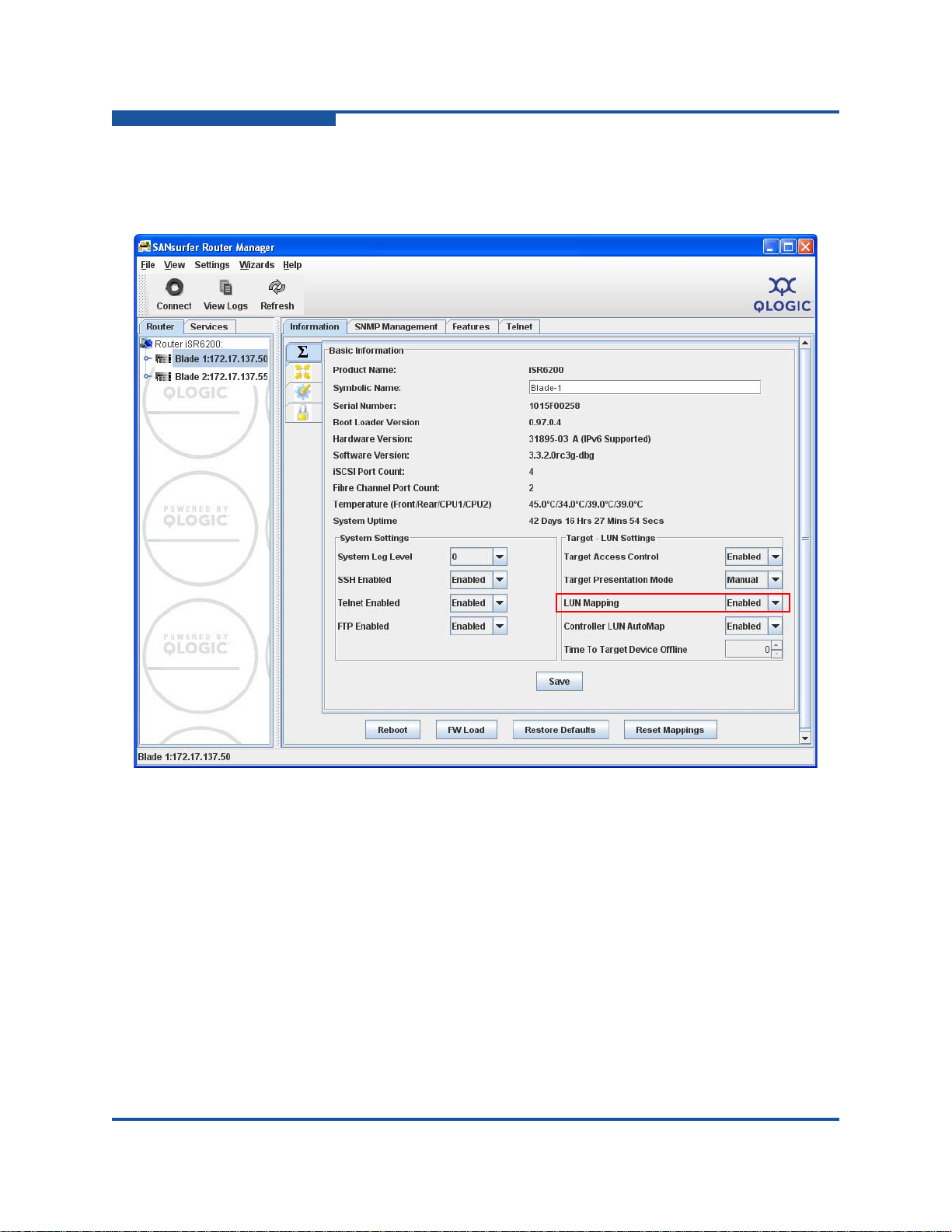
4–Configuration
Controlling per-Host LUN Access on the iSR6200
Figure 4-24 shows how to enable LUN mapping on an iSR6200 blade 1. To apply
these changes, you must click Save, type the system password, and then reboot
the router blade.
Figure 4-24. Enabling LUN Mapping
4-30 ISR651101-00 J
Page 97

Controlling per-Host LUN Access on the iSR6200
NOTE
Host accessible LUNs
Storage Array
21:00:00:c0:dd:13:16:f8
21:01:00:c0:dd:13:16:f8
21:02:00:c0:dd:13:16:f8
21:00:00:c0:dd:13:16:f8
21:00:00:c0:dd:13:16:f9
iSR6200
Blade 1
FC1
FC2
Host Entities
Host Entity 0
21:01:00:c0:dd:13:16:f8
21:01:00:c0:dd:13:16:f9
Host Entity 1
21:02:00:c0:dd:13:16:f8
21:02:00:c0:dd:13:16:f9
Host Entity 2
21:00:00:c0:dd:13:16:f9
21:01:00:c0:dd:13:16:f9
21:02:00:c0:dd:13:16:f9
LUN 1
LUN 2
LUN 3
LUN 4
LUN 5
LUN 6
iqn.2004-08.com:isr6200.0834e00019.r1.00.20030020c2075970
iqn.2004-08.com:isr6200.0834e00019.r1.00.20030020c2075970
iqn.2004-08.com:isr6200.0834e00019.r1.00.20030020c2075970
LUN 1
LUN 3
LUN 2
LUN 4
LUN 5
LUN 6
Figure 4-25 shows host LUN access with LUN Mapping disabled.
4–Configuration
Figure 4-25. Host LUN Access with LUN Masking Disabled
The iSR6200 router can access LUNs only after the host logs into iSR6200
presented iSCSI target(s).
ISR651101-00 J 4-31
Page 98

4–Configuration
Controlling per-Host LUN Access on the iSR6200
4-32 ISR651101-00 J
Page 99

5 Fibre Channel over IP
Fibre Channel over IP (FCIP) is a protocol used to transport Fibre Channel frames
over TCP/IP, thus providing SAN over WAN capabilities. FCIP is commonly used
to interconnect (merge) SANs that are separated by such a distance that a direct
connection is cost prohibitive or technically unfeasible.
This chapter provides the following information:
FCIP Attributes lists the attributes of FCIP implementation in the iSR6200.
“Configuring FCIP” on page 5-2 explains the parameters used in setting up
FCIP, E_Port and F_Port extensions, WAN characteristics, data
compression, bandwidth, and TCP window settings.
FCIP Attributes
The iSR6200 system FCIP implementation has the following attributes:
Compatible with all Fibre Channel vendor fabrics (all Fibre Channel
switches)
E_Port extension—Bridges same Fibre Channel vendor SANs (such as
Fibre Channel switches)
F_Port extension—Does not merge fabrics
Supported configurations:
Two same-vendor Fibre Channel SAN islands
Direct connect from one N_Port to a remote SAN island
Support for 1GbE and 10GbE connections:
100MBps on each 1Gb Ethernet or 8Gb Fibre Channel route
400MBps on each 10Gb Ethernet or 8Gb Fibre Channel route
Compression at 1.5Gbps
TCP/IP selective acknowledgement (SACK) of packets
Support for bandwidth throttling
Distances up to 250ms with TCP window size up to 16M
Trace route and ping support
ISR651101-00 J 5-1
Page 100

5–Fibre Channel over IP
Configuring FCIP
Links up to two locations per blade, four locations per chassis (two blades)
®
FICON
support
Configuring FCIP
To successfully configure FCIP, you need to assess both the SAN and WAN
environments. The following list is provided to support the assessment.
Extension port type:
E_Port—See “E_Port Extension” on page 5-62.2 for a description and
examples.
F_Port—See “F_Port Extension” on page 5-8 for a description and
examples.
For E_Ports, the number of ISLs (inter-switch links):
One
Two
WAN characteristics:
Round-trip time (RTT)—See “Round-Trip Time” on page 5-11
Data rate—See “Link Data Rate” on page 5-12
Quality—See “Link Quality” on page 5-12
Firewall—See“Firewall” on page 5-15
Available WAN bandwidth—See “Bandwidth Limiting” on page 5-16
5-2 ISR651101-00 J
 Loading...