

Page 1
Installation Guide
HyperStack Cable
9000 Series Stackable Chassis Switch
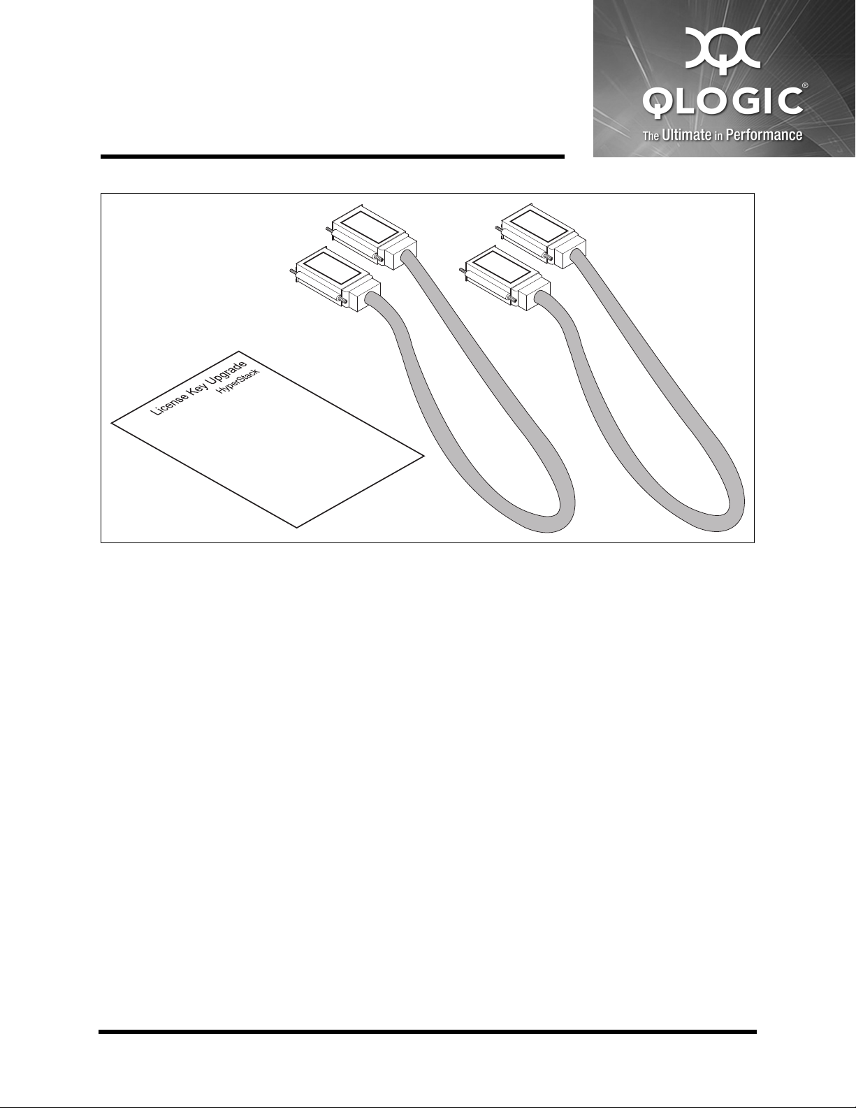
1. HyperStack Cables, 25 inch (2) 2. License Key Upgrade, HyperStack (1)
HyperStacking connects two QLogic 9200 model switches through the Inter-Chassis Connection (ICC)
ports on the two pairs of CPU blades. Two HyperStack™ kits are required to successfully connect two
switches. Each HyperStack kit contains one HyperStack license key and two cables. HyperStacking is
not disruptive and can be done with both switches operational or both switches powered off.
Tools Required
Crosshead screwdriver, medium
Tie wraps (6)
59238-02 A 1
*59238-02 A*
Page 2
Installation Guide HyperStack Cable 9000 Series Stackable Chassis Switch
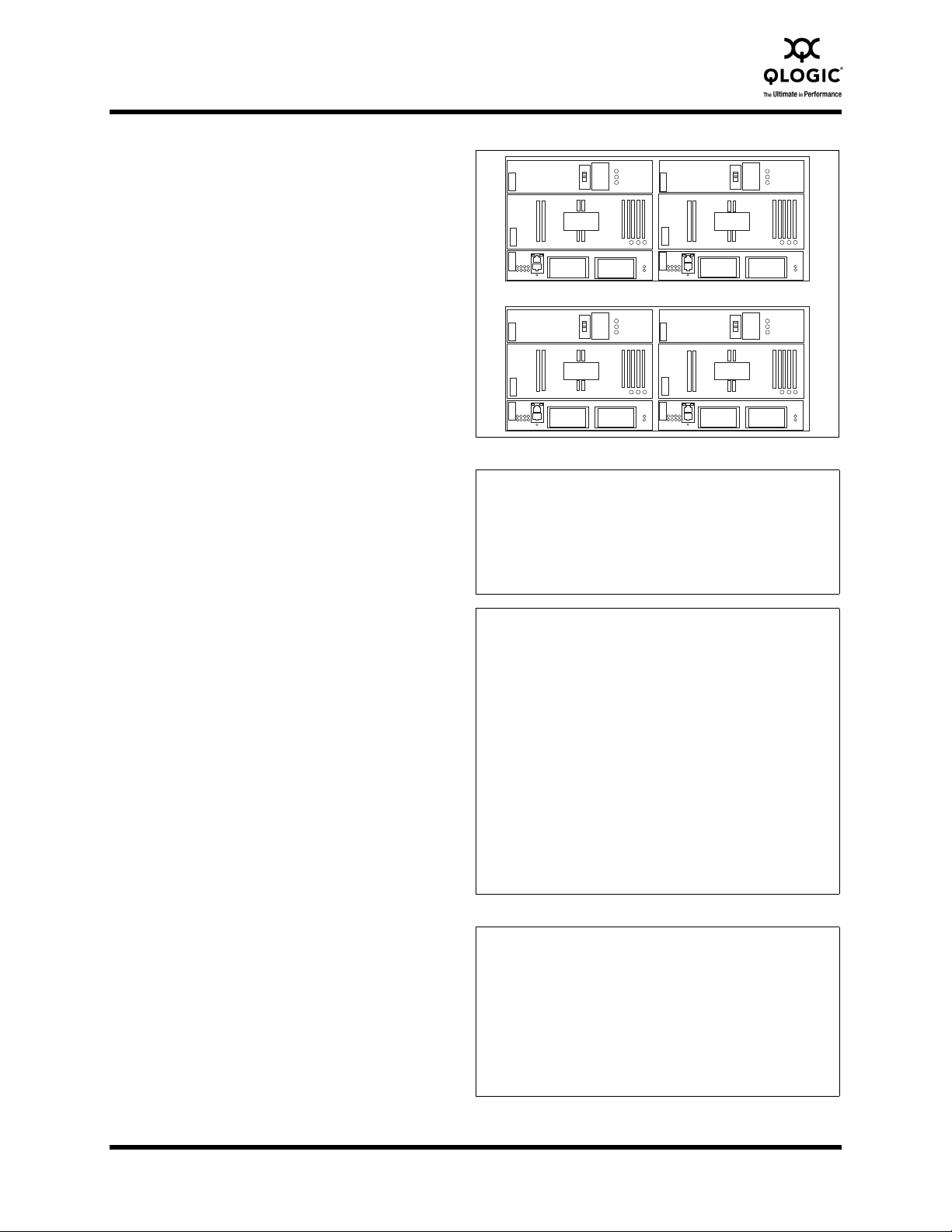
1U Maximum
Mount the Switches
Mount the switches in a rack, one on top of the
other with no more than 1U of space between
them. A cable loom can be installed in this
space.
Horizontal clearance from the CPU blades to the
rack opening or door should be 7–8 inches to
allow for HyperStack cabling.
Refer to the QLogic 9000 Series Stackable
Chassis Switch Rack Mounting Guide for
detailed mounting instructions.
Verify Domain IDs
Verify that the two switches have different
domain IDs. If they do not, change the domain ID
of one of the switches using the
Set Config Switch command.
Verify Firmware Version 7.8
Enter the Show Version command to verify that
the two switches have firmware version 7.8 or
later.
Switch #> show domains
Principal switch is (local): 10:00:00:c0:dd:07:4a:e8
Domain ID List:
Domain 1 (0x1 ) WWN = 10:00:00:c0:dd:07:4a:e8
Switch #>show version
SystemDescription QLogic 9000 Series
HostName <undefined>
EthIPv4NetworkAddress 10.20.11.192
EthIPv6NetworkAddress ::
MACAddress 00:c0:dd:00:71:ee
WorldWideName 10:00:00:c0:dd:00:71:ed
ChassisSerialNumber FAM033100024
SymbolicName Switch
ActiveSWVersion V7.8.x.x.xx.xx
ActiveTimestamp day month date time year
POSTStatus Passed
PrimaryCPU CPU0
SecondaryCPUStatus HotStandby
Install version 7.8 firmware, if necessary. Enter
the Image command to download and unpack
the firmware. Enter the Hotreset command to
Switch #> admin start
Switch (admin) #> image fetch account_name ip_address
filename
perform a non-disruptive activation.
Switch (admin) $> image unpack filename
Wait for the unpack to complete.
Image unpack command result: Passed
Switch (admin) $> hotreset
2 59238-02 A
Page 3

Installation Guide HyperStack Cable 9000 Series Stackable Chassis Switch
1
2
Install HyperStack Licenses
Follow the directions on the License Key
Upgrade document for each switch. Apply the
respective license keys to each switch using the
Feature Add command.
Connect the HyperStack
Cables
Use a screwdriver to remove the covers from all
ICC ports.
Connect a HyperStack cable to one of the ICC
ports with the label side up as shown.
Secure the cable connector with the captive
screws.
Switch #> admin start
Switch (admin) #> feature add #-XXXXXXXXXXXXX
License upgradefor HyperStack(tm) capability.
This feature upgrade does NOT require a switch reset.
Do you want to continue with license upgrade
procedure? (y/n): [n] y
Log Msg: [day mon date hh:mm:ss.sss CST
year][C][8400.006B][Switch][Upgrading License for
HyperStack(tm)capability]
Log Msg: [day mon date hh:mm:ss.sss CST
year][C][8400.0047][Switch][New licenses are being
installed]
1. ICC Port Cover 2. Label facing up
Complete the HyperStack
Cable Connections
Connect the remaining HyperStack cable
connectors as shown in the illustration. These
copper cables are very flexible and can be bent
as needed without damage.
NOTE:
This is the only cabling configuration that is
supported. Any other configuration will result in
an error.
59238-02 A 3
Page 4

Installation Guide HyperStack Cable 9000 Series Stackable Chassis Switch
1
1
1
Secure the HyperStack Cables
Secure the cables in place using ties wraps as
shown. Secure the outer cables to the rack
posts; secure the inner cables to each other. This
reduces cable clearance to 7–8 inches and
provides room for the removal of the Power
Supply and Fan blades on the lower switch.
1. Tie Wraps
Confirm HyperStack Operation
Confirm that the ICC port Logged-In LEDs on all
CPU blades are illuminated. This indicates that
the switches are communicating.
Enter the Show Interconnect command to
confirm each ICC port is online.
Enter the Show Fabric
Switch #> show fabric
command to confirm that
both QLogic 9000 Series
switches are in the fabric.
Corporate Headquarters QLogic Corporation 26650 Aliso Viejo Parkway Aliso Viejo, CA 92656 949.389.6000 www.qlogic.com
International Offices UK | Ireland | Germany | France | India | Japan | China | Hong Kong | Singapore | Taiwan
Domain WWN Enet IP Addr FC IP Addr SymbolicName
------ --- ------------ ---------- ------------
*1 (0x01) 10:00:00:c0:dd:07:4a:e8 10.20.83.203 0.0.0.0 QLogic 9000
2 (0x02) 10:00:00:c0:dd:00:6a:2d 10.20.68.12 0.0.0.0 QLogic 9000
* indicates principal switch
1. Logged-In LEDs
Switch #> show interconnect
Blade ID ICC ID State LSDB ID ISOREASON
-------- ------ ----- ------- ---------
CPU0 ICC0 Online 0x1000 NotApplicable
ICC1 Online 0x1001 NotApplicable
CPU1 ICC0 Online 0x1010 NotApplicable
ICC1 Online 0x1011 NotApplicable
© 2011 QLogic Corporation. Specifications are subject to change without notice. All rights reserved worldwide. QLogic, the QLogic logo, and HyperStack are trademarks or registered trademarks of QLogic Corporation. All other brand and product names are trademarks or registered trademarks of their respective owners. Information supplied by QLogic Corporation is believed to
be accurate and reliable. QLogic Corporation assumes no responsibility for any errors in this brochure. QLogic Corporation reserves the right, without notice, to make changes in product
design or specifications.
 Loading...