

Page 1

0
Simplify
SANbox2-8c/16 Switch Management
User’s Guide
Firmware Version 5.0
59022-11 A Page i
Page 2

SANbox2-8c/16 Switch Management
User’s Guide
Information furnished in this manual is believed to be accurate and reliable. However, QLogic Corporation assumes no
responsibility for its use, nor for any infringements of patents or other rights of third parties which may result from its
use. QLogic Corporation reserves the right to change product specifications at any time without notice. Applications
described in this document for any of these products are for illustrative purposes only. QLogic Corporation makes no
representation nor warranty that such applications are suitable for the specified use without further testing or
modification. QLogic Corporation assumes no responsibility for any errors that may appear in this document.
This product is covered by one or more of the following patents: 6697359; other patents pending.
QLogic, SANsurfer Switch Manager, SANbox, SANbox2, SANsurfer, and SANblade are trademarks or
registered trademarks of QLogic Corporation.
Gnome is a trademark of the GNOME Foundation Corporation.
Java and Solaris are registered trademarks of Sun Microsystems, Inc.
Linux is a registered trademark of Linus Torvalds.
Mac OS X and Safari are registered trademarks of Apple Computer, Inc.
Microsoft, Windows NT, and Windows 2000, and Internet Explorer are trademarks of Microsoft Corporation.
Netscape Navigator and Mozilla are trademarks or registered trademarks of Netscape Communications
Corporation.
Red Hat is a registered trademark of Red Hat Software Inc.
All other brand and product names are trademarks or registered trademarks of their respective owners.
0
Document Revision History
Release, Revision A, February 2005
© 2000–2005 QLogic Corporation
First Printed: May 2001
All Rights Reserved Worldwide.
Printed in U.S.A.
Page ii 59022-11 A
Page 3

Table of Contents
Section 1 Introduction
1.1 Intended Audience ............................................................................................. 1-1
1.2 Related Materials ............................................................................................... 1-1
1.3 JDOM License.................................................................................................... 1-2
1.4 Technical Support............................................................................................... 1-3
1.4.1 Availability.................................................................................................. 1-3
1.4.2 Training......................................................................................................1-3
1.4.3 Contact Information ................................................................................... 1-3
Section 2 Using SANsurfer Switch Manager
2.1 Workstation Requirements................................................................................. 2-2
2.2 Installing the Management Application............................................................... 2-2
2.2.1 SANsurfer Switch Manager ....................................................................... 2-3
2.2.2 SANsurfer Management Suite................................................................... 2-4
2.2.2.1 SMS Installation for Windows........................................................... 2-4
2.2.2.2 SMS Installation for Linux................................................................. 2-6
2.2.2.3 SMS Installation for Solaris...............................................................2-7
2.3 Starting SANsurfer Switch Manager................................................................... 2-9
2.4 Exiting SANsurfer Management Suite.............................................................. 2-12
2.5 Uninstalling SANsurfer Switch Manager .......................................................... 2-13
2.5.1 SMS Uninstall.......................................................................................... 2-14
2.5.2 Standalone Uninstall................................................................................ 2-15
2.6 Changing the Encryption Key for the Default Fabric View File......................... 2-15
2.7 Saving and Opening Fabric View Files ............................................................ 2-16
2.8 Setting SANsurfer Switch Manager Preferences ............................................. 2-16
2.9 Using Online Help ............................................................................................ 2-18
2.10 Viewing Software Version and Copyright Information ...................................... 2-18
59022-11 A Page iii
Page 4

SANbox2-8c/16 Switch Management
User’s Guide
2.11 SANsurfer Switch Manager User Interface ...................................................... 2-19
2.11.1 Menu Bar................................................................................................. 2-20
2.11.1.1 Topology Display Menu .................................................................. 2-20
2.11.1.2 Faceplate Display Menu ................................................................. 2-21
2.11.1.3 Shortcut Keys ................................................................................. 2-21
2.11.2 Tool Bar ................................................................................................... 2-22
2.11.3 Fabric Tree .............................................................................................. 2-23
2.11.4 Graphic Window ...................................................................................... 2-24
2.11.5 Data Window and Tabs............................................................................ 2-24
2.11.6 Working Status Indicator.......................................................................... 2-24
2.12 Using the Topology Display.............................................................................. 2-25
2.12.1 Switch and Link Status ............................................................................ 2-25
2.12.2 Working with Switches and Links ............................................................ 2-26
2.12.2.1 Selecting Switches and Links ......................................................... 2-26
2.12.2.2 Arranging Switches in the Display .................................................. 2-26
2.12.3 Opening the Faceplate Display and Topology Popup Menus.................. 2-27
2.12.4 Topology Data Windows.......................................................................... 2-27
2.13 Using the Faceplate Display............................................................................. 2-28
2.13.1 Port Views and Status ............................................................................. 2-28
2.13.2 Working with Ports...................................................................................2-29
2.13.2.1 Selecting Ports................................................................................2-29
2.13.2.2 Opening the Faceplate Popup Menu.............................................. 2-30
2.13.3 Faceplate Data Windows......................................................................... 2-31
0
Section 3 Managing Fabrics
3.1 RADIUS Servers ................................................................................................ 3-1
3.1.1 Adding a RADIUS Server .......................................................................... 3-2
3.1.2 Removing a RADIUS Server ..................................................................... 3-4
3.1.3 Editing RADIUS Server Information .......................................................... 3-5
3.1.4 Modifying Authentication Order RADIUS Server Information.................... 3-6
Page iv 59022-11 A
Page 5

SANbox2-8c/16 Switch Management
0
3.2 Securing a Fabric ............................................................................................... 3-7
3.2.1 Connection Security .................................................................................. 3-7
3.2.2 User Account Security............................................................................... 3-8
3.2.3 Security Consistency Checklist ................................................................. 3-8
3.2.4 Device Security..........................................................................................3-9
3.2.4.1 Edit Security Dialog ........................................................................ 3-10
3.2.4.2 Creating a Security Set................................................................... 3-11
3.2.4.3 Create Security Group Dialog......................................................... 3-12
3.2.4.4 Creating a Security Group .............................................................. 3-13
3.2.4.5 Create Security Group Member Dialog........................................... 3-14
3.2.4.6 Creating a Security Group Member................................................ 3-15
3.2.4.7 Editing the Security Configuration on a Switch............................... 3-16
3.2.4.8 Viewing Properties of a Security Set, Group, or Member............... 3-17
3.2.4.9 Using the Security Config Dialog.................................................... 3-17
3.2.4.10 Archiving a Security Configuration to a File.................................... 3-18
3.2.4.11 Activating a Security Set................................................................. 3-18
3.2.4.12 Deactivating a Security Set ............................................................ 3-18
3.2.4.13 Configured Security Data Window.................................................. 3-19
3.2.4.14 Active Security Data Window..........................................................3-19
3.2.5 Fabric Services........................................................................................ 3-19
3.2.5.1 Enabling SNMP Configuration........................................................ 3-19
3.2.5.2 Enabling In-band Management ......................................................3-20
3.3 Tracking Fabric Firmware and Software Versions............................................ 3-20
3.3.1 Saving a Version Snapshot ..................................................................... 3-20
3.3.2 Viewing and Comparing Version Snapshots............................................3-21
3.3.3 Exporting Version Snapshots to a File..................................................... 3-21
3.4 Managing the Fabric Database ........................................................................ 3-22
3.4.1 Adding a Fabric ....................................................................................... 3-22
3.4.2 Removing a Fabric .................................................................................. 3-23
3.4.3 Opening a Fabric View File ..................................................................... 3-23
3.4.4 Saving a Fabric View File........................................................................ 3-24
3.4.5 Rediscovering a Fabric............................................................................ 3-24
3.4.6 Adding a New Switch to a Fabric............................................................. 3-24
3.4.7 Replacing a Failed Switch ....................................................................... 3-25
3.4.8 Deleting Switches and Links.................................................................... 3-26
User’s Guide
59022-11 A Page v
Page 6

SANbox2-8c/16 Switch Management
User’s Guide
3.5 Displaying Fabric Information...........................................................................3-26
3.5.1 Fabric Status............................................................................................ 3-27
3.5.2 Displaying the Event Browser.................................................................. 3-28
3.5.2.1 Filtering the Event Browser ............................................................3-30
3.5.2.2 Sorting the Event Browser.............................................................. 3-31
3.5.2.3 Saving the Event Browser to a File ................................................ 3-31
3.5.3 Devices Data Window ............................................................................. 3-32
3.5.4 Active Zone Set Data Window................................................................. 3-33
3.5.5 Link Data Window.................................................................................... 3-34
3.6 Working with Device Information and Nicknames............................................ 3-34
3.6.1 Displaying Detailed Device Information................................................... 3-34
3.6.2 Exporting Device Information to a File..................................................... 3-35
3.6.3 Managing Device Port Nicknames .......................................................... 3-35
3.6.3.1 Creating a Nickname ...................................................................... 3-35
3.6.3.2 Editing a Nickname......................................................................... 3-36
3.6.3.3 Deleting a Nickname ...................................................................... 3-36
3.6.3.4 Exporting Nicknames to a File........................................................ 3-36
3.6.3.5 Importing a Nicknames File ............................................................ 3-37
0
Page vi 59022-11 A
Page 7

SANbox2-8c/16 Switch Management
0
3.7 Zoning a Fabric ................................................................................................ 3-37
3.7.1 Zoning Concepts ..................................................................................... 3-37
3.7.1.1 Zones.............................................................................................. 3-38
3.7.1.2 Aliases ............................................................................................ 3-39
3.7.1.3 Zone Sets ....................................................................................... 3-39
3.7.1.4 Zoning Database ............................................................................ 3-40
3.7.2 Using the Zoning Wizard ......................................................................... 3-41
3.7.3 Managing the Zoning Database .............................................................. 3-41
3.7.3.1 Editing the Zoning Database .......................................................... 3-42
3.7.3.2 Configuring the Zoning Database................................................... 3-44
3.7.3.3 Saving the Zoning Database to a File............................................. 3-45
3.7.3.4 Restoring the Zoning Database from a File.................................... 3-46
3.7.3.5 Restoring the Default Zoning Database..........................................3-46
3.7.3.6 Removing All Zoning Definitions..................................................... 3-46
3.7.4 Managing Zone Sets ............................................................................... 3-47
3.7.4.1 Creating a Zone Set .......................................................................3-47
3.7.4.2 Activating and Deactivating a Zone Set.......................................... 3-48
3.7.4.3 Copying a Zone to a Zone Set........................................................ 3-48
3.7.4.4 Removing a Zone from a Zone Set or from All Zone Sets.............. 3-49
3.7.4.5 Removing a Zone Set..................................................................... 3-49
3.7.5 Managing Zones...................................................................................... 3-50
3.7.5.1 Creating a Zone in a Zone Set .......................................................3-50
3.7.5.2 Adding Zone Members ................................................................... 3-51
3.7.5.3 Renaming a Zone or a Zone Set .................................................... 3-52
3.7.5.4 Removing a Zone Member ............................................................. 3-52
3.7.5.5 Removing a Zone from a Zone Set ................................................ 3-52
3.7.5.6 Removing a Zone from All Zone Sets............................................. 3-53
3.7.5.7 Changing Zone Types .................................................................... 3-53
3.7.6 Managing Aliases .................................................................................... 3-53
3.7.6.1 Creating an Alias ............................................................................ 3-54
3.7.6.2 Adding a Member to an Alias ......................................................... 3-54
3.7.6.3 Removing an Alias from All Zones ................................................. 3-55
3.7.7 Merging Fabrics and Zoning.................................................................... 3-55
3.7.7.1 Zone Merge Failure ........................................................................ 3-55
3.7.7.2 Zone Merge Failure Recovery ........................................................ 3-56
User’s Guide
59022-11 A Page vii
Page 8

SANbox2-8c/16 Switch Management
User’s Guide
0
Section 4 Managing Switches
4.1 Managing User Accounts ................................................................................... 4-2
4.1.1 Creating User Accounts............................................................................. 4-3
4.1.2 Removing a User Account.........................................................................4-4
4.1.3 Changing a User Account Password......................................................... 4-5
4.1.4 Modifying a User Account..........................................................................4-6
4.2 Displaying Switch Information ............................................................................ 4-7
4.2.1 Devices Data Window ............................................................................... 4-8
4.2.2 Switch Data Window.................................................................................. 4-8
4.2.3 Port Statistics Data Window .................................................................... 4-12
4.2.4 Port Information Data Window.................................................................4-13
4.2.5 Configured and Active Zonesets Data Window....................................... 4-14
4.3 Configuring Port Threshold Alarms .................................................................. 4-15
4.4 Paging a Switch................................................................................................ 4-16
4.5 Setting the Date/Time and Enabling NTP Client .............................................. 4-17
4.6 Resetting a Switch............................................................................................ 4-17
4.7 Configuring a Switch ........................................................................................ 4-19
4.7.1 Using the Configuration Wizard............................................................... 4-19
4.7.2 Switch Properties..................................................................................... 4-20
4.7.2.1 Symbolic Name .............................................................................. 4-21
4.7.2.2 Switch Administrative States........................................................... 4-21
4.7.2.3 Domain ID and Domain ID Lock ..................................................... 4-22
4.7.2.4 Fabric Device Management Interface............................................. 4-23
4.7.2.5 Broadcast Support.......................................................................... 4-24
4.7.2.6 In-band Management .....................................................................4-24
4.7.3 Advanced Switch Properties.................................................................... 4-25
4.7.3.1 Interop Mode for Zoning ................................................................. 4-25
4.7.3.2 Legacy Port Address Format.......................................................... 4-26
4.7.3.3 Timeout Values ............................................................................... 4-26
4.7.4 System Services Dialog........................................................................... 4-27
4.7.5 Security Consistency Checklist Dialog .................................................... 4-28
4.7.6 Network Properties.................................................................................. 4-29
4.7.6.1 IP Configuration.............................................................................. 4-30
4.7.6.2 Remote Logging ............................................................................. 4-31
4.7.6.3 NTP Client ...................................................................................... 4-31
4.7.7 SNMP Properties..................................................................................... 4-32
4.7.7.1 SNMP Configuration....................................................................... 4-33
4.7.7.2 SNMP Trap Configuration...............................................................4-34
4.8 Archiving a Switch............................................................................................ 4-35
Page viii 59022-11 A
Page 9

SANbox2-8c/16 Switch Management
0
4.9 Restoring a Switch ........................................................................................... 4-36
4.10 Restoring the Factory Default Configuration .................................................... 4-38
4.11 Downloading a Support File ............................................................................. 4-39
4.12 Installing Firmware ........................................................................................... 4-40
4.13 Displaying Hardware Status ............................................................................. 4-41
User’s Guide
Section 5 Managing Ports
5.1 Displaying Port Information ................................................................................ 5-1
5.1.1 Monitoring Port Status ............................................................................... 5-2
5.1.1.1 Displaying Port Types....................................................................... 5-2
5.1.1.2 Displaying Port Operational States................................................... 5-3
5.1.1.3 Displaying Port Speeds .................................................................... 5-3
5.1.1.4 Displaying Transceiver Media Status................................................ 5-4
5.1.2 Port Statistics Data Window ...................................................................... 5-4
5.1.3 Port Information Data Window...................................................................5-7
5.2 Configuring Ports.............................................................................................. 5-10
5.2.1 Changing Port Administrative States ....................................................... 5-11
5.2.2 Changing Port Speeds ............................................................................ 5-12
5.2.3 Changing Port Types ............................................................................... 5-13
5.2.4 I/O Stream Guard .................................................................................... 5-13
5.2.5 Device Scan ............................................................................................ 5-14
5.2.6 Changing Port Symbolic Name ............................................................... 5-14
5.3 Using the Extended Credits Wizard ................................................................. 5-14
5.4 Resetting a Port................................................................................................ 5-16
5.5 Testing Ports..................................................................................................... 5-16
5.6 Graphing Port Performance ............................................................................. 5-18
5.6.1 Starting SANsurfer Performance Viewer ................................................. 5-19
5.6.2 Exiting SANsurfer Performance Viewer................................................... 5-20
5.6.3 Saving and Opening Performance View Files......................................... 5-21
5.6.4 Changing the Default Performance View File Encryption Key ................ 5-22
5.6.5 Setting SANsurfer Performance Viewer Preferences.............................. 5-22
5.6.6 Setting the Polling Frequency.................................................................. 5-23
5.6.7 Displaying Graphs ................................................................................... 5-23
5.6.7.1 Arranging Graphs in the Display..................................................... 5-24
5.6.7.2 Customizing Graphs ....................................................................... 5-24
5.6.7.3 Setting Global Graph Type ............................................................. 5-26
5.6.7.4 Rescaling a Selected Graph........................................................... 5-26
5.6.8 Saving Graph Statistics to a File.............................................................. 5-26
59022-11 A Page ix
Page 10

SANbox2-8c/16 Switch Management
User’s Guide
0
Appendix A Command Line Interface
A.1 Logging On to a Switch ......................................................................................A-1
A.2 User Accounts....................................................................................................A-2
A.3 Working with Switch Configurations...................................................................A-2
A.3.1 Modifying a Configuration..........................................................................A-3
A.3.2 Backing up and Restoring Switch Configurations......................................A-4
A.4 Commands .........................................................................................................A-6
Admin Command.......................................................................................A-8
Alias Command .........................................................................................A-9
CIM Command ........................................................................................A-11
CIMListener Command............................................................................A-12
CIMSubscription Command.....................................................................A-14
Config Command.....................................................................................A-16
Create Command ....................................................................................A-19
Date Command .......................................................................................A-22
Firmware Install Command......................................................................A-23
Group Command.....................................................................................A-24
Hardreset Command ...............................................................................A-32
Help Command........................................................................................A-33
History Command....................................................................................A-34
Hotreset Command .................................................................................A-35
Image Command.....................................................................................A-36
Lip Command ..........................................................................................A-39
Passwd Command ..................................................................................A-40
Ping Command........................................................................................A-41
Ps Command...........................................................................................A-42
Quit Command ........................................................................................A-43
Reset Command......................................................................................A-44
Security Command..................................................................................A-52
Securityset Command .............................................................................A-56
Set Command..........................................................................................A-58
Set Config Command ..............................................................................A-60
Set Log Command...................................................................................A-71
Set Port Command..................................................................................A-75
Set Setup Command ...............................................................................A-77
Show Command......................................................................................A-87
Show Config Command.........................................................................A-103
Show Log Command.............................................................................A-106
Show Perf Command ............................................................................A-109
Page x 59022-11 A
Page 11

0
Glossary
Index
SANbox2-8c/16 Switch Management
User’s Guide
Show Setup Command.......................................................................... A-111
Shutdown Command............................................................................. A-115
Test Command ...................................................................................... A-116
Uptime Command..................................................................................A-119
User Command .....................................................................................A-120
Whoami Command................................................................................A-123
Zone Command.....................................................................................A-124
Zoneset Command................................................................................A-128
Zoning Command..................................................................................A-130
59022-11 A Page xi
Page 12

SANbox2-8c/16 Switch Management
User’s Guide
0
Figures
Figure Page
2-1 Initial Startup Dialog..................................................................................................... 2-10
2-2 SANsurfer Switch Manager Window............................................................................ 2-11
2-3 Save Default Fabric View File Dialog...........................................................................2-12
2-4 Load Default Fabric File Dialog.................................................................................... 2-13
2-5 Preferences Dialog – SANsurfer Switch Manager ....................................................... 2-17
2-6 SANsurfer Switch Manager Display Elements............................................................. 2-19
2-7 Topology Display Menu................................................................................................2-20
2-8 Faceplate Display Menu............................................................................................... 2-21
2-9 Fabric Tree................................................................................................................... 2-23
2-10 Topology Display..........................................................................................................2-25
2-11 Faceplate Display......................................................................................................... 2-28
3-1 Add Server ..................................................................................................................... 3-2
3-2 Remove Server .............................................................................................................. 3-4
3-3 Edit Radius Server Information ...................................................................................... 3-5
3-4 Modify Authentication Order - Radius Server Information.............................................. 3-6
3-5 Edit Security Dialog...................................................................................................... 3-10
3-6 Create Security Group Dialog ...................................................................................... 3-12
3-7 Create a Security Group Member Dialog..................................................................... 3-14
3-8 Security Config Dialog.................................................................................................. 3-17
3-9 Fabric Version Snapshot Analysis Dialog .................................................................... 3-21
3-10 Add a New Fabric Dialog ............................................................................................. 3-22
3-11 Events Browser............................................................................................................ 3-28
3-12 Filter Events Dialog...................................................................................................... 3-30
3-13 Active Zone Set Data Window ..................................................................................... 3-33
3-14 Detailed Devices Display Dialog .................................................................................. 3-34
3-15 Edit Zoning Dialog........................................................................................................ 3-42
3-16 Zoning Config Dialog....................................................................................................3-44
4-1 User Account Administration Dialog – Add Account ...................................................... 4-3
4-2 User Account Administration Dialog – Remove Account ............................................... 4-4
4-3 User Account Administration Dialog– Change Password .............................................. 4-5
4-4 User Account Administration Dialog – Modify Account.................................................. 4-6
4-5 Faceplate Display...........................................................................................................4-7
4-6 Faceplate Display - Port Information............................................................................4-13
4-7 Configured Zonesets Data Window ............................................................................. 4-14
4-8 Port Threshold Alarm Configuration Dialog.................................................................. 4-15
4-9 Port Threshold Alarm Example .................................................................................... 4-16
4-10 Switch Properties Dialog.............................................................................................. 4-20
4-11 Advanced Switch Properties Dialog............................................................................. 4-25
4-12 System Services Dialog ............................................................................................... 4-27
4-13 Network Properties Dialog ........................................................................................... 4-29
4-14 SNMP Properties Dialog .............................................................................................. 4-32
4-15 Restore Dialogs – Full and Selective ........................................................................... 4-36
4-16 Hardware Status LEDs................................................................................................. 4-41
Page xii 59022-11 A
Page 13

SANbox2-8c/16 Switch Management
0
5-1 Faceplate Display - Port Information..............................................................................5-1
5-2 Port Properties Dialog.................................................................................................. 5-10
5-3 Designate Donor Ports................................................................................................. 5-15
5-4 Port Loopback Test Dialog........................................................................................... 5-16
5-5 Fabric View Graphs...................................................................................................... 5-18
5-6 Save Default Performance View File Dialog ................................................................ 5-20
5-7 Load Default Performance File Dialog ......................................................................... 5-21
5-8 Preferences – SANsurfer Performance Viewer............................................................ 5-22
5-9 Default Graph Options Dialog ...................................................................................... 5-24
User’s Guide
Tables
Table Page
2-1 Workstation Requirements............................................................................................. 2-2
2-2 Tool Bar Buttons .......................................................................................................... 2-22
3-1 Topology Display Switch and Status Icons .................................................................. 3-27
3-2 Severity Levels............................................................................................................. 3-29
3-3 Devices Data Window Entries...................................................................................... 3-32
3-4 Edit Zoning Dialog Tool Bar Buttons and Icons ........................................................... 3-43
4-1 Factory User Accounts...................................................................................................4-2
4-2 Switch Data Window Entries.......................................................................................... 4-8
4-3 Switch Resets .............................................................................................................. 4-18
4-4 Switch Administrative States........................................................................................4-21
4-5 Timeout Values ............................................................................................................ 4-26
4-6 IP Configuration Parameters........................................................................................ 4-30
4-7 SNMP Configuration Parameters................................................................................. 4-33
4-8 SNMP Trap Configuration Parameters ........................................................................ 4-34
4-9 Factory Default Configuration Settings ........................................................................ 4-38
5-1 Port Types...................................................................................................................... 5-2
5-2 Port Operational States.................................................................................................. 5-3
5-3 Port Speeds ...................................................................................................................5-3
5-4 Transceiver Media View................................................................................................. 5-4
5-5 Port Statistics Data Window Entries............................................................................... 5-5
5-6 Port Information Data Window Entries........................................................................... 5-7
5-7 Port Administrative States............................................................................................ 5-11
5-8 Port Speeds .................................................................................................................5-12
5-9 Port Types.................................................................................................................... 5-13
A-1 Command-Line Completion ...........................................................................................A-6
A-2 Commands Listed by Authority Level.............................................................................A-7
A-3 CIM Listener Configuration Parameters.......................................................................A-12
A-4 CIM Subscription Configuration Parameters................................................................A-14
A-5 ISL Group Member Attributes ......................................................................................A-25
A-6 Port Group Member Attributes .....................................................................................A-26
A-7 MS Group Member Attributes ......................................................................................A-27
A-8 Group Member Attributes.............................................................................................A-28
A-9 Switch Configuration Defaults ......................................................................................A-46
59022-11 A Page xiii
Page 14

SANbox2-8c/16 Switch Management
User’s Guide
A-10 Port Configuration Defaults..........................................................................................A-47
A-11 Port Threshold Alarm Configuration Defaults...............................................................A-48
A-12 Zoning Configuration Defaults......................................................................................A-48
A-13 SNMP Configuration Defaults ......................................................................................A-49
A-14 RADIUS Configuration Defaults...................................................................................A-50
A-15 Services Configuration Defaults...................................................................................A-50
A-16 System Configuration Defaults.....................................................................................A-51
A-17 Security Configuration Defaults....................................................................................A-51
A-18 Set Config Port Parameters .........................................................................................A-60
A-19 Security Configuration Parameters ..............................................................................A-63
A-20 Set Config Switch Parameters .....................................................................................A-63
A-21 Set Config Threshold Parameters................................................................................A-65
A-22 Set Config Zoning Parameters.....................................................................................A-66
A-23 RADIUS Service Settings.............................................................................................A-77
A-24 Switch Services Settings..............................................................................................A-79
A-25 SNMP Configuration Settings ......................................................................................A-81
A-26 System Configuration Settings.....................................................................................A-82
A-27 Show Port Parameters.................................................................................................A-90
A-28 Switch Operational Parameters ...................................................................................A-93
A-29 Zoning Database Limits .............................................................................................A-131
0
Page xiv 59022-11 A
Page 15

Section 1
Introduction
This manual describes the switch management tools which include the SANsurfer
Switch Manager™ application (version 5.00) and the Command Line Interface
(CLI) for the SANbox2 Fibre Channel switch (firmware version 5.0). The
SANsurfer Switch Manager switch management application is the primary focus
of this manual which is organized as follows:
Section 1 describes the intended audience for this manual, related
materials, and technical support.
Section 2 describes how to use SANsurfer Switch Manager, its menus, and
its displays.
Section 3 describes fabric management tasks.
Section 4 describes switch management tasks.
Section 5 describes port and device management tasks.
Appendix A describes the command line interface.
A glossary of terms and an index are also provided.
1.1
Intended Audience
This manual introduces the switch management products and explains their
installation and use. It is intended for users responsible for installing and using
switch management tools.
1.2
Related Materials
Refer to the following manuals for information about switch hardware and
installation.
SANbox2-8c Fibre Channel Switch Installation Guide, publication number
59042-08 Rev. A.
SANbox2-16 Fibre Channel Switch Installation Guide, publication number
59021-11 Rev. A.
59022-11 A 1-1
Page 16

1 – Introduction
JDOM License
1.3
JDOM License
This product includes software developed by the JDOM Project
(http://www.jdom.org/). Copyright (C) 2000-2002 Brett McLaughlin & Jason
Hunter. All rights reserved.
Redistribution and use in source and binary forms, with or without modification,
are permitted provided that the following conditions are met:
1. Redistributions of source code must retain the above copyright notice, this
2. Redistributions in binary form must reproduce the above copyright notice,
3. The name "JDOM" must not be used to endorse or promote products
4. Products derived from this software may not be called "JDOM", nor may
0
list of conditions, and the following disclaimer.
this list of conditions, and the disclaimer that follows these conditions in the
documentation and/or other materials provided with the distribution.
derived from this software without prior written permission. For written
permission, please contact license@jdom.org.
"JDOM" appear in their name, without prior written permission from the
JDOM Project Management (pm@jdom.org).
In addition, we request (but do not require) that you include in the end-user
documentation provided with the redistribution and/or in the software itself an
acknowledgement equivalent to the following: "This product includes software
developed by the JDOM Project (http://www.jdom.org/)."
Alternatively, the acknowledgment may be graphical using the logos available at
http://www.jdom.org/images/logos.
THIS SOFTWARE IS PROVIDED ``AS IS'' AND ANY EXPRESSED OR IMPLIED
WARRANTIES, INCLUDING, BUT NOT LIMITED TO, THE IMPLIED
WARRANTIES OF MERCHANTABILITY AND FITNESS FOR A PARTICULAR
PURPOSE ARE DISCLAIMED. IN NO EVENT SHALL THE JDOM AUTHORS
OR THE PROJECT CONTRIBUTORS BE LIABLE FOR ANY DIRECT,
INDIRECT, INCIDENTAL, SPECIAL, EXEMPLARY, OR CONSEQUENTIAL
DAMAGES (INCLUDING, BUT NOT LIMITED TO, PROCUREMENT OF
SUBSTITUTE GOODS OR SERVICES; LOSS OF USE, DATA, OR PROFITS;
OR BUSINESS INTERRUPTION) HOWEVER CAUSED AND ON ANY THEORY
OF LIABILITY, WHETHER IN CONTRACT, STRICT LIABILITY, OR TORT
(INCLUDING NEGLIGENCE OR OTHERWISE) ARISING IN ANY WAY OUT OF
THE USE OF THIS SOFTWARE, EVEN IF ADVISED OF THE POSSIBILITY OF
SUCH DAMAGE.
This software consists of voluntary contributions made by many individuals on
behalf of the JDOM Project and was originally created by Brett McLaughlin
<brett@jdom.org> and Jason Hunter <jhunter@jdom.org>. For more information
on the JDOM Project, please see <http://www.jdom.org/>.
1-2 59022-11 A
Page 17

0
1.4
Technical Support
Customers should contact their authorized maintenance provider for technical
support of their QLogic switch products. QLogic-direct customers may contact
QLogic Technical Support; others will be redirected to their authorized
maintenance provider.
Visit the QLogic support Web site listed in Contact Information for the latest
firmware and software updates.
1.4.1
Availability
QLogic Technical Support is available from 7:00 AM to 7:00 PM Central Standard
Time, Monday through Friday, excluding QLogic-observed holidays.
1.4.2
Training
QLogic offers certification training for the technical professional for both the
SANblade™ HBAs and the SANbox2™ switches. From the training link at
www.qlogic.com, you may choose Electronic-Based Training or schedule an
intensive "hands-on" Certification course.
1 – Introduction
Technical Support
Technical Certification courses include installation, maintenance and
troubleshooting QLogic SAN products. Upon demonstrating knowledge using live
equipment, QLogic awards a certificate identifying the student as a Certified
Professional. The training professionals at QLogic may be reached by email at
tech.training@qlogic.com
1.4.3
Contact Information
Telephone: +1 952-932-4040
Fax: +1 952-932-4018
Email:
Technical Service
Technical Training
QLogic Web Site: www.qlogic.com
Technical Support Web Site: support.qlogic.com
support@qlogic.com
tech.training@qlogic.com
59022-11 A 1-3
Page 18

1 – Introduction
Technical Support
Notes
0
1-4 59022-11 A
Page 19

Section 2
Using SANsurfer Switch Manager
This section describes how to use the SANsurfer Switch Manager application and
its menus. The following topics are covered:
Workstation Requirements
Installing the Management Application
Starting SANsurfer Switch Manager
Exiting SANsurfer Management Suite
Uninstalling SANsurfer Switch Manager
Changing the Encryption Key for the Default Fabric View File
Saving and Opening Fabric View Files
Setting SANsurfer Switch Manager Preferences
Using Online Help
Viewing Software Version and Copyright Information
SANsurfer Switch Manager User Interface
Using the Topology Display
Using the Faceplate Display
59022-11 A 2-1
Page 20

2 – Using SANsurfer Switch Manager
Workstation Requirements
2.1
Workstation Requirements
The requirements for fabric management workstations running SANsurfer Switch
Manager are described in Table 2-1:
0
Table 2-1. Workstation Requirements
Operating System
Memory 256 MB or more
Disk Space 150 MB per installation
Processor 500 MHz or faster
Hardware
Internet Browser Microsoft® Internet Explorer® 5.0 and later
Telnet workstations require an RJ-45 Ethernet port or an RS-232 serial port and
an operating system with a Telnet client.
2.2
Windows® 2000, 2003, and XP
Solaris™ 8, 9, and 10
Linux® Red Hat® EL 3.x
S.u.S.E® Linux 9.0 Enterprise
Mac OS X® 10.3
CD-ROM drive,
Netscape® Navigator® 4.72 and later
Mozilla™ 1.02 and later
Safari®
Java 2 Run Time Environment to support the web applet
RJ-45 Ethernet port, RS-232 serial port (optional)
Installing the Management Application
You can manage the switch using SANsurfer Switch Manager as a standalone
application or as a part of SANsurfer Management Suite™. SANsurfer
Management Suite is QLogic’s integrated fabric management application,
managing both HBAs and switches.
If your switch was shipped with a SANsurfer Switch Manager Disk, refer to
”SANsurfer Switch Manager” on page 2-3 for instructions on how to install
SANsurfer Switch Manager.
If your switch was shipped with a SANsurfer Management Suite Disk, refer
to ”SANsurfer Management Suite” on page 2-4 for instructions on how to
install and upgrade SANsurfer Management Suite.
2-2 59022-11 A
Page 21

0
2.2.1
SANsurfer Switch Manager
You can install SANsurfer Switch Manager on a Windows, Linux, Solaris, or
Mac OS X workstation. To install the SANsurfer Switch Manager application from
the SANsurfer Switch Manager Installation Disk, do the following:
For a Windows platform:
1. Close all programs currently running, and insert the SANsurfer Switch
Manager Installation Disk into the management workstation CD-ROM drive.
2. In the upper left corner of the product introduction screen, click
Management Software.
3. Locate your platform in the table and click Install.
If the product introduction screen does not open in step 2, open the CD with
Windows Explorer and run the installation program with the following path:
data\files\Management_Software\Windows\Windows_5.00.xx.xx.exe
For a Linux platform:
2 – Using SANsurfer Switch Manager
Installing the Management Application
Open the CD and run the installation program with the following path:
data/files/Management_Software/Linux/Linux_5.00.xx.xx.bin
If there is no CD-ROM icon, do the following:
1. Open an xterm or other terminal window.
2. Mount the CD-ROM. From a shell prompt, enter the following:
mount /mnt/cdrom
3. Change directory to the location of the install program:
cd /mnt/cdrom/data/files/Management_Software/Linux
4. Execute the install program and follow the installation instructions.
Linux_5.00.xx.xx.bin
For a Solaris platform:
1. Open a terminal window. If the disk isn’t already mounted, enter the
following command:
volcheck
2. Enter following command to move to the directory on the CD that contains
the executable:
cd /cdrom/cdrom0/data/files/Management_Software/solaris
3. Execute the install program and follow the installation instructions:
Solaris_5.00.xx.xx.bin
59022-11 A 2-3
Page 22

2 – Using SANsurfer Switch Manager
Installing the Management Application
For a Mac OS X platform:
1. Open the CD and move to the following folder:
data/files/Management_Software/MacOSX
2. Double click the applicaton zip file (MacOSX_5.00.xx_xxxx.zip). This
will place the install program on your desktop.
3. Locate the Install program icon on your desktop, execute it, and follow
the installation instructions.
2.2.2
SANsurfer Management Suite
The following instructions describe how to install SANsurfer Management Suite
and upgrade SANsurfer Switch Manager. You can install SANsurfer Management
Suite (SMS) on a Windows, Linux, or Solaris workstation. Choose the instructions
for your workstation:
SMS Installation for Windows
SMS Installation for Linux
0
SMS Installation for Solaris
2.2.2.1
SMS Installation for Windows
Close all programs currently running, and insert the SANsurfer Management Suite
Installation Disk into the management workstation CD-ROM drive.
1. If the SANsurfer Management Suite start page does not open in your default
browser, do the following:
a. Using Windows Explorer, double-click the drive letter which contains
the SANsurfer Management Suite Disk.
b. Locate and double-click the Start_Here.htm file to open the SANsurfer
Management Suite start page in your default browser.
2. On the SANsurfer Management Suite start page, click the SANbox Switch
Software button.
3. On the SANbox Switch Software page, scroll to the SANbox2-8c/16 Series
area.
4. In the Operating System column, click the Win NT/2000 link.
5. Click the SANsurfer Management Software link to open the File Download
dialog.
2-4 59022-11 A
Page 23

0
2 – Using SANsurfer Switch Manager
Installing the Management Application
6. You can run the installation file from the CD-ROM or download the
installation file to your hard drive. Choose one of the following:
Open the installation file from the CD-ROM and follow the SANsurfer
Switch Manager installation instructions.
Specify a location in which to save the
sansurfer_windows_install.exe file, and click the Save button.
Double-click the saved sansurfer_windows_install.exe file and
follow the installation instructions.
7. When the installation is complete, start SANsurfer Management Suite using
the SANsurfer file from the SANsurfer Management Suite installation
directory. You can also start SANsurfer Management Suite by clicking the
SANsurfer icon (if installed) on the desktop or from the Start menu. In SMS,
Click the Switch tab in the left pane. From the Help menu, select About ...
and make note of the version number. Close SANsurfer Management Suite.
8. To ensure you are using the most recent version of SANsurfer Switch
Manager, visit the QLogic support web page and go to Drivers, Software and
Manuals.
a. Select your switch model from the pull-down menu. Locate the
description for SANsurfer Switch Manager for Windows under
"Management Software".
b. If the release version number (5.00.xx) is greater than what is currently
installed, download the new version and proceed to step 9. Otherwise,
no upgrade is needed and the SMS installation is complete.
9. To start the installer, open the zip file and run the
SANsurferSwitchMgr_Windows_5.00.xx.exe file.
10. When prompted for an installation directory, click the Choose button and
select the same folder as the SANsurfer Management Suite installation in
step 6. The default SMS installation directory is C:\Program Files\QLogic
Corporation\SANsurfer. Click the Next button.
11. When prompted for the location in which to create the program icons, click
the In an Existing Group radio button, then specify the same group that
was used for the SMS installation. The default SMS group is "QLogic
Management Suite". Click the Next button.
12. Click the Install button to the start the installation. When the installation is
complete, click the Done button.
13. In the SMS install directory, enter the following command to execute the
chglax.bat file. If prompted to overwrite an existing file, enter Y to do so.
chglax.bat
14. Restart SANsurfer Switch Manager from SANsurfer Management suite as
you did in step 7 and confirm that the new version is running.
59022-11 A 2-5
Page 24

2 – Using SANsurfer Switch Manager
Installing the Management Application
2.2.2.2
SMS Installation for Linux
Close all programs currently running, and insert the SANsurfer Management Suite
Installation Disk into the management workstation CD-ROM drive.
1. If a file browser dialog opens showing icons for the contents of the CD-ROM,
double-click the Start_Here.htm file to open the SANsurfer Management
Suite start page. If a file browser does not open, double-click the CD-ROM
icon to open the browser. If there is no CD-ROM icon, do the following:
a. Open an xterm or other terminal window.
b. Mount the CD-ROM. From a shell prompt, enter the following
command:
mount /mnt/cdrom
c. Execute your web browser to view the Start_Here.htm document
using one of the following commands:
mozilla file:/mnt/cdrom/Start_Here.htm
0
or
netscape file:/mnt/cdrom/Start_Here.htm
d. The SANsurfer Management Suite start page opens in your browser.
2. On the SANsurfer Management Suite start page, click the SANbox Switch
Software button.
3. On the SANbox Switch Software page, scroll to the SANbox2-8c/16 Series
area.
4. In the Operating System column, click the Linux link.
5. Click the SANsurfer Management Software link to open the File Download
dialog.
6. Enter a path name to save the sansurfer_linux_install.bin file, and click
the Save button.
7. Open a terminal window for the directory in which the
sansurfer_linux_install.bin file was saved, and make the file executable.
chmod +x sansurfer_linux_install.bin
8. Execute the install program and follow the installation instructions
./sansurfer_linux_install.bin
9. When the installation is complete, start SANsurfer Management Suite using
the SANsurfer file in the installation directory. Click the Switch tab from the
left pane to open SANsurfer Switch Manager. From the Help menu, select
About ... and make note of the release version number. Close SANsurfer
Management Suite.
2-6 59022-11 A
Page 25

0
2 – Using SANsurfer Switch Manager
Installing the Management Application
10. To ensure that you are using the most recent version of SANsurfer Switch
Manager, visit the QLogic support web page and go to Drivers, Software and
Manuals.
a. Select your switch model from the pull-down menu. Locate the
description for SANsurfer Switch Manager for Linux under
"Management Software".
b. If the release version number (5.00.xx) is greater than what is currently
installed on your workstation, down load the new version and proceed
to step 11. Otherwise, no upgrade is needed and the SMS installation
is complete.
11. From the tar.gz file, extract the SANsurferSwitchMgr_Linux_5.00.xx.bin
file and make the file executable.
chmod +x sansurferswitchmgr_linux_5.02.xx.bin
12. Execute the install program and follow the installation instructions.
./sansurferswitchmgr_linux_5.02.xx.bin
13. When prompted for an installation directory, click the Choose button and
select the same folder as the SANsurfer Management Suite installation in
step 9. The default SMS installation directory is
/opt/QLogic_Corporation/SANsurfer.
14. Enter the following script command from the installation directory:
./chglax
15. Start SANsurfer Switch Manager from SANsurfer Management suite as you
did in step 9 and confirm that the new version is running.
2.2.2.3
SMS Installation for Solaris
To install the SANsurfer Switch Manager application on Solaris from the
SANsurfer Management Suite CD-ROM, do the following:
1. Insert the SANsurfer Management Suite Disk into the management
workstation CD-ROM drive. If the SANsurfer Management Suite start page
does not open in your default browser, do the following:
a. Right-click the Workspace Menu.
b. Select File, then select File Manager.
c. In File Manager, double-click the CD-ROM folder, and then
double-click the Sansurfer folder.
d. In the Sansurfer folder, double-click the Start_Here.htm file to open
the SANsurfer Management Suite start page in your default browser.
2. On the SANsurfer Management Suite start page, click the SANbox Switch
Software button.
59022-11 A 2-7
Page 26

2 – Using SANsurfer Switch Manager
Installing the Management Application
3. On the SANbox Switch Software page, scroll to the SANbox2-8c/16 Series
area.
4. In the Operating System column, click the Solaris SPARC link.
5. Click the SANsurfer Management Software link to open the Save As
dialog.
6. Enter a path name to save the sansurfer_solaris_install.bin file and click
the Save button.
7. Open a terminal window for the directory in which the
sansurfer_solaris_install.bin file was saved, and enter the following:
chmod +x sansurfer_solaris_install.bin
8. Execute the install program and follow the installation instructions:
./sansurfer_solaris_install.bin
9. When the installation is complete, start SANsurfer Management Suite using
the SANsurfer file in the installation directory. Click the Switch tab from the
left pane to open SANsurfer Switch Manager. From the Help menu, select
About ... and make note of the release version number. Close SANsurfer
Management Suite.
0
10. To ensure that you are using the most recent version of SANsurfer Switch
Manager, visit the QLogic support web page and go to Drivers, Software and
Manuals.
a. Select your switch model from the pull-down menu. Locate the
description for SANsurfer Switch Manager for Linux under
"Management Software".
b. If the release version number (5.00.xx) is greater than what is currently
installed on your workstation, down load the new version. Otherwise,
no upgrade is needed.
11. Open the tar file and save the
SANsurferSwitchMgr_QLGCsol_5.00.xx.bin file in a folder and make the
file executable.
# chmod +x sansurferswitchmgr_QLGCsol_5.00.xx
12. Install the new SANsurfer Switch Manager package:
# pkgadd -d sansurferswitchmgr_QLGCsol_5.00.xx
13. Change directories to the package location:
# cd /usr/opt/QLGCsol/bin
14. Locate and execute the file sbm_over_sms.sh:
# ./sbm_over_sms.sh
2-8 59022-11 A
Page 27

0
15. When prompted for the SMS installation directory, enter d if SMS was
installed in it’s default directory (/opt/QLogic_Corporation/SANsurfer).
Otherwise, enter the path name for the SMS installation directory. The script
will copy the necessary files to the specified installation directory.
16. Restart SANsurfer Switch Manager from SANsurfer Management suite as
you did in step 9 and confirm that the new version is running.
2.3
Starting SANsurfer Switch Manager
You can start SANsurfer Switch Manager as a standalone application or from
SANsurfer Management Suite.
Note: After the switch is operational, you can also open the SANsurfer
Switch Manager web applet, by entering the switch IP address in an
internet browser. If your workstation does not have the Java 2 Run
Time Environment program, you will be prompted to download it.
2 – Using SANsurfer Switch Manager
Starting SANsurfer Switch Manager
To start SANsurfer Switch Manager as a standalone application, do the
following.
1. Start the SANsurfer Switch Manager using one of the following
methods:
For Windows, double-click the SANsurfer Switch Manager
shortcut, or select SANsurfer Switch Manager from Start menu,
depending on how you installed the SANsurfer Switch Manager
application. From a command line, you can enter the
SANsurfer_Switch_Manager command:
<install_directory>SANsurfer_Switch_Manager.exe
For Linux, Solaris, or Mac OS X, enter the
SANsurfer_Switch_Manager command:
<install_directory>./SANsurfer_Switch_Manager
2. In the Initial Start dialog, click the Open Configuration Wizard button.
When you power up the switch, the Configuration Wizard will
recognize the switch and lead you through the configuration process.
59022-11 A 2-9
Page 28

2 – Using SANsurfer Switch Manager
Starting SANsurfer Switch Manager
To start SANsurfer Switch Manager from SANsurfer Management Suite, do
the following.
1. Start the SANsurfer Management Suite application using one of the
following methods:
For Windows, double-click the SANsurfer shortcut, or select
SANsurfer from Start menu, depending on how you installed the
SANsurfer application. From a command line, enter the following
command:
For Linux or Solaris enter the SANsurfer command:
2. From the SANsurfer Management Suite home page, click the
SANsurfer Switch Manager button.
3. In the Initial Start dialog, click the Open Configuration Wizard button.
When you power up the switch, the Configuration Wizard will
recognize the switch and lead you through the configuration process.
0
<install_directory>\SANsurfer.exe
<install_directory>./SANsurfer
The application opens with the Initial Start dialog shown in Figure 2-1. If you prefer
not to see this dialog, check the Don’t show this dialog again check box. This
has the same effect as disabling the Display Initial Startup Dialog preference.
Refer to ”Setting SANsurfer Switch Manager Preferences” on page 2-16 for
information about setting preferences.
Figure 2-1. Initial Startup Dialog
Click the Open Existing Fabric radio button to open the Add a New Fabric
dialog, which prompts you for a fabric name, IP address, account name, and
password. Refer to ”Adding a Fabric” on page 3-22.
2-10 59022-11 A
Page 29

0
2 – Using SANsurfer Switch Manager
Starting SANsurfer Switch Manager
Click the Open Existing Fabric View File radio button to open the Open
View dialog which prompts you to specify a fabric view file that you saved
earlier. Refer to ”Opening a Fabric View File” on page 3-23.
Click the Start Application Without Specifying a Fabric radio button to
open the SANsurfer Switch Manager window shown in Figure 2-2.
Click the Open Configuration Wizard radio button to open the
Configuration Wizard to configure a switch, add a new switch,
replace/restore a switch, or recover or edit an IP configuration of an existing
switch.
Figure 2-2. SANsurfer Switch Manager Window
59022-11 A 2-11
Page 30

2 – Using SANsurfer Switch Manager
Exiting SANsurfer Management Suite
2.4
Exiting SANsurfer Management Suite
To exit a SANsurfer Switch Manager application session, open the File menu and
select Exit. If you have not yet defined an encryption key, the Save Default Fabric
View File dialog, shown in Figure 2-3, prompts you to save the current fabric view
as the default fabric view file. Enter an encryption key in the Default Fabric File
Encryption Key field. Re-enter the encryption key in the Re-enter Encryption Key
to Confirm field. Click the OK button to save the current set of fabrics to the
default fabric view file in the working directory.
0
Figure 2-3. Save Default Fabric View File Dialog
The encryption key is used to encrypt the sensitive data in the default fabric view
file. Refer to ”Changing the Encryption Key for the Default Fabric View File” on
page 2-15 for information about changing this encryption key. If an encryption key
has been defined and the View File Auto Save and Load preferences settings are
set to Enable, the current fabric view is automatically saved to your default fabric
view file upon exit future SANsurfer Switch Manager sessions.
To prevent SANsurfer Switch Manager from prompting you to save the default
fabric view file between SANsurfer Switch Manager sessions, set the View File
Auto Save and Load preferences setting to Enable (default). Refer to ”Setting
SANsurfer Switch Manager Preferences” on page 2-16 for more information.
2-12 59022-11 A
Page 31

0
In your next SANsurfer Switch Manager session, the Load Default Fabric File
dialog shown in Figure 2-4 prompts you to load the default fabric view file and to
specify its encryption key, if there is one. In the Default Fabric File Encryption Key
field, enter the encryption key and click the Load View File button. If you do not
want to load the default fabric view file, click the Continue Without Loading
button to open the SANsurfer Switch Manager with no fabric displayed.
Figure 2-4. Load Default Fabric File Dialog
2.5
Uninstalling SANsurfer Switch Manager
The method you use to uninstall SANsurfer Switch Manager depends on how you
installed it:
2 – Using SANsurfer Switch Manager
Uninstalling SANsurfer Switch Manager
If you installed SANsurfer Switch Manager as part of SANsurfer
Management Suite, you must uninstall SANsurfer Management Suite. Refer
to ”SMS Uninstall” on page 2-14.
If you installed SANsurfer Switch Manager as a standalone program, you
must uninstall SANsurfer Switch Manager directly. Refer to ”Standalone
Uninstall” on page 2-15.
59022-11 A 2-13
Page 32

2 – Using SANsurfer Switch Manager
Uninstalling SANsurfer Switch Manager
2.5.1
SMS Uninstall
A program to uninstall SANsurfer Management Suite was included as part of the
SANsurfer Management Suite installation process. Use this method only if you
installed SANsurfer Switch Manager as part of SANsurfer Management Suite. The
UninstallData folder in the installation directory contains the uninstall program,
SANsurferUninstaller.
The default installation directories are:
For Windows: C:\Program Files\QLogic_Corporation\SANsurfer
For Linux: /opt/QLogic_Corporation/SANsurfer
For Solaris: /opt/QLogic_Corporation/SANsurfer
To uninstall the SANsurfer Management Suite application, do the following:
For Windows, browse for the uninstall program file or the shortcut/link that
points to the uninstall program file. The uninstall program shortcut is in the
same folder as the program shortcut (Start menu, program group, on
desktop, or user specified) that is used to start the SANsurfer Management
Suite application. Double-click the uninstall program file or shortcut/link, and
follow the instructions.
0
For Linux, execute the link to SANsurferUninstaller.
<install_directory>/UninstallerData/SANsurferUninstaller
For Solaris, enter the following command and follow the instructions:
<install_directory>/UninstallData/SANsurferUninstaller
2-14 59022-11 A
Page 33

0
2.5.2
Standalone Uninstall
A program to uninstall SANsurfer Switch Manager was included as part of the
installation process. Use this method only if you installed SANsurfer Switch
Manager as a standalone program. The UninstallerData folder in the Install
directory contains the uninstall program, Uninstall_SANsurfer_Switch_Manager.
Also, a shortcut/link to the uninstall program was installed in the installation
directory during the SANsurfer Switch Manager installation process.
The default installation directories are:
For Windows:
C:\Program Files\QLogic_Corporation\SANsurfer_Switch_Manager
For Linux: /opt/QLogic_Corporation/SANsurfer_Switch_Manager
For Solaris: /usr/opt/QLogic_Corporation/SANsurfer_Switch_Manager
For Mac OS X:
Users/qlogic/Applications/QLogic_Corporation/SANsurfer_Switch_Manager
2 – Using SANsurfer Switch Manager
Changing the Encryption Key for the Default Fabric View File
To uninstall the SANsurfer Switch Manager application, do the following:
For Windows, browse for the uninstall program file or the shortcut/link that
points to the uninstall program file. The uninstall program shortcut is in the
same folder as the program shortcut (Start menu, program group, on
desktop, or user specified) that is used to start the SANsurfer Switch
Manager application. Double-click the uninstall program file or shortcut/link,
and follow the instructions to uninstall the SANsurfer Switch Manager
application.
For Linux, Solaris, or Mac OS X, execute the link to
Uninstall_SANsurfer_Switch_Manager. If no links were created during the
installation, enter the Uninstall_SANsurfer_Switch_Manager command from
the following directory:
UninstallerData/Uninstall_SANsurfer_Switch_Manager
2.6
Changing the Encryption Key for the Default Fabric View File
To change the encryption key for the SANsurfer Switch Manager default fabric
view file, do the following:
1. Open the File menu and select Save Default Fabric View File to open the
Save Default Fabric View File dialog. Enter an encryption key in the Default
Fabric File Encryption Key field.
2. Re-enter the same encryption key in the Re-enter Encryption Key to Confirm
field.
3. Click the OK button to save the current set of fabrics to the default fabric
view file in the working directory.
59022-11 A 2-15
Page 34

2 – Using SANsurfer Switch Manager
Saving and Opening Fabric View Files
2.7
Saving and Opening Fabric View Files
A fabric view file is one or more fabrics saved to a file. In addition to the SANsurfer
Switch Manager default fabric view file, you can save and open your own fabric
view files. To save a set of fabrics to a file, do the following:
1. Open the File menu and select Save View As to open the Save View dialog.
2. Enter a name for the fabric view file or click the Browse button to select an
existing file. Files are saved in the working directory.
3. Enter a password. When you attempt to open this fabric view file, you will be
prompted for this password. If you leave the File Password field blank, no
password will be required when attempting to open this fabric view file.
4. Click the OK button to save the view.
To open a fabric view file, do the following:
1. Open the File menu and select Open View File to open the Open View
dialog.
0
2. Enter a name for the fabric view file or click the Browse button to select an
existing file.
3. If the fabric view file was saved with a password, enter the password and
click the OK button.
4. Click the OK button to open the view.
2.8
Setting SANsurfer Switch Manager Preferences
Using the preferences settings, you can:
Change the location of the working directory in which to save files.
Change the location of the browser used to view the online help. The
Browser Location field is not supported/displayed for Macintosh OS X.
Enable (default) or disable the view file auto save and load feature. Refer to
”Exiting SANsurfer Management Suite” on page 2-12 for more information
on the default fabric view file.
Enable (default) or disable the use of the Initial Start Dialog at the beginning
of a SANsurfer Switch Manager session. Refer to ”Starting SANsurfer
Switch Manager” on page 2-9 for information about the Initial Start Dialog.
After a default fabric view file is created, this setting has no effect.
2-16 59022-11 A
Page 35

0
2 – Using SANsurfer Switch Manager
Setting SANsurfer Switch Manager Preferences
Enable (default) or disable the Event Browser. Refer to ”Displaying the
Event Browser” on page 3-28. If the Event Browser is enabled using the
Preferences dialog shown in Figure 2-5, the next time SANsurfer Switch
Manager is started, all events will be displayed. If the Event Browser is
disabled when SANsurfer Switch Manager is started and later enabled, only
those events from the time the Event Browser was enabled and forward will
be displayed.
Choose the default port view when opening the faceplate display. You can
set the faceplate to reflect the current port type (default), port speed, port
operational state, or port transceiver media. Regardless of the default port
view you choose, you can change the port view in the faceplate display by
opening the View menu and selecting a different port view option. Refer to
the corresponding subsection for more information:
”Displaying Port Types” on page 5-2
”Displaying Port Operational States” on page 5-3
”Displaying Port Speeds” on page 5-3
”Displaying Transceiver Media Status” on page 5-4
Figure 2-5. Preferences Dialog – SANsurfer Switch Manager
To set preferences for your SANsurfer Switch Manager sessions, do the following:
1. Open the File menu, and select Preferences to open the Preferences
dialog.
2. Enter or browse for paths to the working directory and browser.
3. In the Application-wide Options area, choose the preferences you want.
4. Click the OK button to save the changes.
59022-11 A 2-17
Page 36

2 – Using SANsurfer Switch Manager
Using Online Help
2.9
Using Online Help
Online help is available for the SANsurfer Switch Manager application and its
functions. The two ways to open the online help file are: open the Help menu and
select Help Topics, or click the Help button in the tool bar. You can also display
context-sensitive help for all SANsurfer Switch Manager dialogs by clicking the
Help button in the dialog.
2.10
Viewing Software Version and Copyright Information
To view SANsurfer Switch Manager software version and copyright information,
open the Help menu and select About....
0
2-18 59022-11 A
Page 37

0
2.11
SANsurfer Switch Manager User Interface
The SANsurfer Switch Manager application uses two basic displays to manage
the fabric and individual switches: the topology display and the faceplate display.
The topology display shows all switches that are able to communicate and all
connections between switches. The faceplate display shows the front of a single
switch and its ports. Both displays share some common elements as shown in
Figure 2-6.
2 – Using SANsurfer Switch Manager
SANsurfer Switch Manager User Interface
Topology
Display
Fabric
Tree
Faceplate
Display
Menu
Bar
Data Window
Tabs
Too l B ar
Graphic
Window
Data
Window
Working Status
Indicator
Figure 2-6. SANsurfer Switch Manager Display Elements
59022-11 A 2-19
Page 38

2 – Using SANsurfer Switch Manager
SANsurfer Switch Manager User Interface
2.11.1
Menu Bar
The SANsurfer Switch Manager menus and the tasks offered in them vary
depending on the display. For example, the Port menu and many of the Switch
menu selections are only available in the faceplate display.
2.11.1.1
Topology Display Menu
The menu options in the topology display are shown in Figure 2-7.
0
Figure 2-7. Topology Display Menu
2-20 59022-11 A
Page 39

0
2.11.1.2
Faceplate Display Menu
The menu options in the faceplate display are shown in Figure 2-8.
2 – Using SANsurfer Switch Manager
SANsurfer Switch Manager User Interface
The keyboard shortcut keys vary by display type: topology display and faceplate
display. In addition to the menu bar, both the topology and faceplate displays have
context sensitive menus that pop up when you right-click on the switches and links
in the topology display, and on the switch image in the faceplate display. Refer to
”Opening the Faceplate Display and Topology Popup Menus” on page 2-27 for
more information about these popup menus.
2.11.1.3
Shortcut Keys
Shortcut key combinations, available in both the topology and faceplate displays,
provide an alternative method of accessing menu options. The shortcut key
combinations are not case-sensitive. For example, to exit the application, press
Alt+F, then press X.
Figure 2-8. Faceplate Display Menu
59022-11 A 2-21
Page 40

2 – Using SANsurfer Switch Manager
SANsurfer Switch Manager User Interface
2.11.2
Tool Bar
The tool bar consists of a row of graphical buttons that you can use to access
SANsurfer Switch Manager functions as shown in Table 2-2. The tool bar buttons
are an alternative method to using the menu bar. The tool bar can be relocated in
the display by clicking and dragging the handle at the left edge of the tool bar.
Tool Bar Button Description
Add Fabric button - adds a new fabric to the fabric view.
Open View File button - opens an existing fabric view file.
0
Table 2-2. Tool Bar Buttons
Save View As button - saves the current fabric view to a file.
Refresh button - updates the topology or faceplate display with
current information.
Event Browser button - opens the events browser.
Help Topics button - opens the online help file.
Edit Zoning button - opens the Edit Zoning dialog (available only in
faceplate display).
Edit Security button - opens the Edit Security dialog (faceplate
display only with SSL enabled)
Help Topics button - opens the online help file.
The QLogic logo opens a link to the QLogic web site.
2-22 59022-11 A
Page 41

0
2.11.3
Fabric Tree
2 – Using SANsurfer Switch Manager
SANsurfer Switch Manager User Interface
The fabric tree lists the managed fabrics and their switches as shown in
Figure 2-9. The window width can be adjusted by clicking and dragging the
moveable window border. An entry handle located to the left of an entry in the tree
indicates that the entry can be expanded or collapsed. Click this handle or
double-click the entry to expand or collapse a fabric tree entry. A fabric entry
expands to show its member switches.
Fabric
Entry
Entry Handle
Switch
Entries
Moveable
Window Border
Figure 2-9. Fabric Tree
Each fabric tree entry has a small icon next to it that uses color to indicate
operational status.
A green icon indicates normal operation.
A yellow icon indicates that a switch is operational, but may require attention
to maintain maximum performance.
A red icon indicates a potential failure or non-operational state as when the
switch is offline.
A blue icon indicates that a switch is unknown, unreachable, or
unmanageable.
If the status of the fabric is not normal, the fabric icon in the fabric tree will indicate
the reason for the abnormal status. The same message is provided when you rest
the mouse over the fabric icon in the fabric tree.
The fabric tree provides access to the topology and faceplate displays for any
fabric or switch.
To open the topology display from the fabric tree, click a fabric entry.
To open the faceplate display from the fabric tree, click a switch entry.
59022-11 A 2-23
Page 42

2 – Using SANsurfer Switch Manager
SANsurfer Switch Manager User Interface
2.11.4
Graphic Window
The graphic window, as shown in Figure 2-6, presents graphic information about
fabrics and switches such as the fabric topology and the switch faceplate. The
window height can be adjusted by clicking and dragging the window border that it
shares with the data window.
2.11.5
Data Window and Tabs
The data window presents a table of data and statistics associated with the
selected tab. Use the scroll bar to browse through the data. The window length
can be adjusted by clicking and dragging the border that it shares with the graphic
window.
Adjust the column width by moving the pointer over the column heading border
shared by two columns until a right/left arrow graphic is displayed. Click and drag
the arrow to the desired width.
The data window tabs present options for the type of information to display in the
data window. These options vary depending on the display.
0
2.11.6
Working Status Indicator
The working status indicator, located in the lower right corner of the SANsurfer
Switch Manager window, shows when the management workstation is exchanging
information with the fabric. As conditions change, the fabric forwards this
information to the management workstation where it is reflected in the various
displays.
2-24 59022-11 A
Page 43

0
2.12
Using the Topology Display
The topology display shown in Figure 2-10 receives information from the selected
fabric and displays its topology. Switches and inter-switch links (ISLs) appear in
the graphic window and use color to indicate status. Consider the following
topology display features:
Using the Topology Display
Working with Switches and Links
Topology Data Windows
2 – Using SANsurfer Switch Manager
Using the Topology Display
Figure 2-10. Topology Display
2.12.1
Switch and Link Status
Switch icon shape and color provide information about the switch and its
operational state. Lines represent links between switches. The topology display
uses green to indicate normal operation, yellow to indicate operational with errors,
red to indicate a potential failure or non-operational state, and blue to indicate
unknown, unreachable, or unmanageable. Refer to ”Fabric Status” on page 3-27
for more information about topology display icons.
59022-11 A 2-25
Page 44

2 – Using SANsurfer Switch Manager
Using the Topology Display
2.12.2
Working with Switches and Links
Switch and link icons are selectable and moveable, and serve as access points for
other displays and menus. You select switches and links to display information
about them, modify their configuration, or delete them from the display.
Context-sensitive popup menus are displayed when you right-click on a switch or
link icon, or in the background of the topology display and graphic window.
2.12.2.1
Selecting Switches and Links
Selected switch icons are highlighted in light blue. Selected ISLs are displayed as
a heavier line. You can select switches and links in the following ways:
To select a switch or a link, click the icon or link.
To select multiple switches or links, hold down the Control key and select.
To select all switches or links, right-click anywhere in the graphic window
background. Select Select All Switches or Select All Links from the popup
menu.
0
To cancel a selection, press and hold the Control key, and select the item again.
To cancel all selections, click in the graphic window background.
2.12.2.2
Arranging Switches in the Display
You can arrange individual switch icons in the topology display or allow SANsurfer
Switch Manager to arrange all switch icons for you:
To move an individual switch icon, click and drag the icon to another location
in the graphic window. Links stretch or contract to remain connected.
To arrange all switch icons in the topology display automatically, open the
View menu and select Layout Topology.
By default, the Toggle Auto Layout box in the View menu is checked which
causes SANsurfer Switch Manager to arrange the icons when you select Layout
Topology.
You can save a custom arrangement, or layout, and restore that layout during a
SANsurfer Switch Manager session. Begin by arranging the icons, then open the
View menu and select Remember Layout. To restore the saved layout, open the
View menu, uncheck the Toggle Auto Layout box, and select Layout Topology.
2-26 59022-11 A
Page 45

2 – Using SANsurfer Switch Manager
0
2.12.3
Using the Topology Display
Opening the Faceplate Display and Topology Popup Menus
The faceplate display shows the front of a single switch and its ports. To open the
faceplate display when viewing the topology display, click the switch entry/icon in
the fabric tree, or double-click the switch graphic.
The topology display also offers a fabric, switch, and a link popup menu:
To open the fabric popup menu, right-click the graphic window background.
The fabric popup menu presents selections to refresh the fabric, select all
switches, select all links, or layout topology.
To open the switch popup menu, right-click the switch icon in the graphic
window. The switch popup menu presents selections to refresh the switch,
delete the switch from the display, open the Switch Properties dialog, or
open the Network Properties dialog.
To open the link popup menu, right-click the link. The Link popup menu
presents a selection to delete the link from the display.
2.12.4
Topology Data Windows
The topology display provides the following data windows corresponding to the
data window tabs:
Devices – displays all devices logged with the name server and their
addresses within the current fabric configuration, and displays information
from the fabric and allows devices to register certain information with the
fabric. Refer to ”Devices Data Window” on page 4-8 for more information.
Active Zoneset – displays the active zone set for the fabric including zones
and their member ports. Refer to ”Active Zone Set Data Window” on
page 3-33 for more information about this data window. Refer to ”Zoning a
Fabric” on page 3-37 for information about zone sets and zones.
Switch – displays current network and switch configuration data for the
selected switches. Refer to ”Switch Data Window” on page 4-8 for more
information.
Link – displays information about the inter-switch links. Refer to ”Link Data
Window” on page 3-34 to for more information.
59022-11 A 2-27
Page 46

2 – Using SANsurfer Switch Manager
Using the Faceplate Display
2.13
Using the Faceplate Display
The faceplate display shown in Figure 2-11 displays the switch name and
operational state, and port status. Consider the following functional elements of
the faceplate display:
Port Views and Status
Faceplate Data Windows
0
Figure 2-11. Faceplate Display
2.13.1
Port Views and Status
Port color and text provide information about the port and its operational state.
Green indicates active; gray indicates inactive. The faceplate display provides the
following views of port status corresponding to the View menu options in the
faceplate display. Refer to ”Monitoring Port Status” on page 5-2 for more
information about these displays.
Port type
Port state
Port speed
Port media
2-28 59022-11 A
Page 47

0
2.13.2
Working with Ports
Ports are selectable and serve as access points for other displays and menus.
You select ports to display information about them in the data window or to modify
them. Context-sensitive popup menus and properties dialogs are displayed when
you right-click the faceplate image or port icons in the faceplate display.
2.13.2.1
Selecting Ports
You can select ports in the following ways. Selected ports are outlined in white.
To select a port, click the port in the faceplate display.
To select a range of consecutive ports, select a port, then press and hold the
shift key and select another port. The application selects both end ports and
all ports in between in port number sequence.
To select several non-consecutive ports, hold the Control key while
selecting.
2 – Using SANsurfer Switch Manager
Using the Faceplate Display
To select all ports, right-click the faceplate image in the graphic window.
Select Select All Ports from the popup menu.
To cancel a selection, press and hold the Control key and select it again.
59022-11 A 2-29
Page 48

2 – Using SANsurfer Switch Manager
Using the Faceplate Display
2.13.2.2
Opening the Faceplate Popup Menu
To open the popup menu, right-click the faceplate image to present the following
tasks.
Refresh the switch
Select all ports
Manage switch properties
Manage network properties
Manage SNMP properties
Extended credits wizard
Manage port properties
Change the port symbolic name
Run the port loopback tests
Services
0
Security Consistency Checklist
If no ports are selected, the port-related tasks will be unavailable in the menu.
Right-click a port to open the Port popup menu. Hold down the Shift or Control key
to select more than one port. If multiple ports are selected, right-click one of the
selected ports.
2-30 59022-11 A
Page 49

0
2.13.3
Faceplate Data Windows
The faceplate display provides the following data windows corresponding to the
data window tabs:
Devices – displays information about devices (hosts and storage targets)
connected to the switch.
Switch – displays current switch configuration data.
Port Statistics – displays performance data for the selected ports.
Port Information – displays information for the selected ports.
Configured Zonesets – displays all zone sets, zones, and zone membership
in the zoning database.
Configured Security – displays all security definitions currently saved in the
database.
Active Security – displays the active security set.
2 – Using SANsurfer Switch Manager
Using the Faceplate Display
59022-11 A 2-31
Page 50

2 – Using SANsurfer Switch Manager
Using the Faceplate Display
Notes
0
2-32 59022-11 A
Page 51

This section describes the following tasks that manage fabrics:
RADIUS Servers
Securing a Fabric
Tracking Fabric Firmware and Software Versions
Managing the Fabric Database
Displaying Fabric Information
Working with Device Information and Nicknames
Zoning a Fabric
3.1
RADIUS Servers
Remote Authentication Dial In User Service (RADIUS) provides a method to
centralize the management of authentication passwords in larger networks. It has
a client/server model, where the server is the password repository and third party
authentication point and the clients are all of the managed devices. RADIUS can
be configured for devices and/or user accounts. The RADIUS server dialogs are
available only on a secure fabric connection (SSL) and on the entry switch (out of
band switch). Refer to ”Connection Security” on page 3-7 and ”System Services
Dialog” on page 4-27 for more information.
Section 3
Managing Fabrics
RADIUS is designed to authenticate users and devices using a
challenge/response protocol. Basic implementations consist of a central RADIUS
server containing a database of authorized users as well as authentication
information. A RADIUS client wishing to verify the authenticity of a user issues a
challenge to the user and collects the response to the challenge. This information
is forwarded to the RADIUS server for authentication and the server responds
with the results, either an accept or reject. The RADIUS client does not need to be
configured with any user authentication information, this all resides on the
RADIUS server and can be managed centrally and separately from the clients. In
addition, no passwords are exchanged between the RADIUS server and its
clients. Authentication of requests from a RADIUS client to the server and
responses from the server to a client can also be authenticated. This requires
sharing a secret between the server and client. The accounting RADIUS supports
the auditing of the users and switch services such as Telnet, FTP, and switch
management applications.
59022-11 A 3-1
Page 52

3 – Managing Fabrics
RADIUS Servers
3.1.1
Adding a RADIUS Server
When you add a RADIUS server, you provide a method to centralize the
management of authentication passwords over a network.
0
Figure 3-1. Add Server
To add a RADIUS server, do the following:
1. Open the faceplate display, open the Switch menu, and select Radius
Servers....
2. In the Radius Server Information dialog, shown in Figure 3-1, click the Add
Server tab.
3. Select the server type (Device, User, Account).
4. In the IP Address field, enter the remote IP address of the server.
5. In the UDP Port field, enter the remote UDP port number of the
Authentication Radius Server. The Radius Accounting Server UDP port will
always be the value of Device/User Authentication Server UDP Port + 1.
6. In the Timeout field, enter the timeout value in seconds (minimum of 1
second, maximum of 30 seconds). This is the number of seconds the
RADIUS client will wait for a response from the RADIUS server before
retrying, or giving up on a request.
3-2 59022-11 A
Page 53

0
3 – Managing Fabrics
RADIUS Servers
7. In the Retries field, enter the the number of retries. This is the maximum
number of times the RADIUS client will retry a request sent to the primary
RADIUS server.
8. Select the Sign Packet check box to enable the switch to include a digital
signature (Message-Authenticator) in all RADIUS access request packets
sent to the RADIUS server. A valid Message-Authenticator attribute will be
required in all RADIUS server responses.
9. In the Secret field, enter the server secret. A secret is required for all
RADIUS servers. The secret is used when generating and checking the
Message-Authenticator attribute.
10. Click the Add Server button to add the server, and click the Close button to
exit the dialog.
11. Click the Modify Authentication Order tab, and verify that Device
Authentication Order and User Authentication Order options are set to either
Radius or Radius Local for Radius Authentication to be implemented.
59022-11 A 3-3
Page 54

3 – Managing Fabrics
RADIUS Servers
3.1.2
Removing a RADIUS Server
When you remove a RADIUS server, you disable the management of
authentication usernames and passwords over the network for that server.
0
Figure 3-2. Remove Server
To remove a RADIUS server, do the following:
1. Open the faceplate display, open the Switch menu, and select Radius
Servers....
2. In the Radius Server Information dialog, shown in Figure 3-2, click the
Remove Server tab.
3. In server list at the top of the dialog, select the server to be removed.
4. Click the Remove Server button to remove the server, and click the Close
button to exit the dialog.
3-4 59022-11 A
Page 55

0
3.1.3
Editing RADIUS Server Information
Editing information of a RADIUS server involves changing the configuration of a
RADIUS server.
3 – Managing Fabrics
RADIUS Servers
Figure 3-3. Edit Radius Server Information
To edit information of a RADIUS server, do the following:
1. Open the faceplate display, open the Switch menu, and select Radius
Servers....
2. In the Radius Server Information dialog, shown in Figure 3-3, click the Edit
Server tab.
3. In server list at the top of the dialog, select the server to be edited.
4. Make changes to the IP Address, UDP Port, Timeout, Retries, and Secret
fields.
5. Select or unselect the server type (Device, User, Account) and Sign Packet
check boxes.
6. Click the Edit Server button to save the changes, and click the Close button
to exit the dialog.
59022-11 A 3-5
Page 56

3 – Managing Fabrics
RADIUS Servers
3.1.4
Modifying Authentication Order RADIUS Server Information
Editing information of a RADIUS server involves changing the configuration of a
RADIUS server.
0
Figure 3-4. Modify Authentication Order - Radius Server Information
To modify the authentication order information of a RADIUS server, do the
following:
1. Open the faceplate display, open the Switch menu, and select Radius
Servers....
2. In the Radius Server Information dialog, shown in Figure 3-4, click the
Modify Authentication Order tab.
3. In server list at the top of the dialog, select the server to be modified.
4. Make changes to the Device Authentication Order or User Authentication
Order pull-down menus. Select Local, Radius, or Radius Local.
5. Click the Modify Order button to save the changes, and click the Close
button to exit the dialog.
3-6 59022-11 A
Page 57

0
3.2
Securing a Fabric
Fabric security consists of the following:
Connection Security
User Account Security
Security Consistency Checklist
Device Security
Fabric Services
3.2.1
Connection Security
Connection security provides an encrypted data path for switch management
methods. The switch supports the Secure Shell (SSH) protocol for the command
line interface and the Secure Socket Layer (SSL) protocol for management
applications such as SANsurfer Switch Manager and Common Information
Module (CIM).
3 – Managing Fabrics
Securing a Fabric
The SSL handshake process between the workstation and the switch involves the
exchanging of certificates. These certificates contain the public and private keys
that define the encryption. The switch certificate is valid for one year beginning
with its creation date and time. The workstation validates the switch certificate by
comparing the workstation date and time to the switch certificate creation date and
time. For this reason, it is important to snychronize the workstation and switch with
the same date, time, and time zone. If a certificate has not been created by the
user, the switch will automatically create one.
Consider your requirements for connection security: for the command line
interface (SSH), management applications such as SANsurfer Switch Manager
(SSL), or both. If SSL connection security is required, also consider using the
Network Time Protocol (NTP) to synchronize workstations and switches.
59022-11 A 3-7
Page 58

3 – Managing Fabrics
Securing a Fabric
3.2.2
User Account Security
User account security is the process by which your user account and password
are authenticated with the list of valid user accounts and passwords. The switch
validates your account and password when you attempt to add a fabric using
SANsurfer Switch Manager or log in to a switch through Telnet. Your system
administrator defines accounts, passwords, and authority levels that are stored on
the switch. Refer to ”Managing User Accounts” on page 4-2 for more information.
The Admin account possesses Admin authority which grants full access to all
tasks of the SANsurfer Switch Manager menu system. The switch validates your
user account and SANsurfer Switch Manager grants access to its menus
according to your authority level. If you do not have Admin authority, you are
limited to monitoring tasks.
Note: If a user is logged into a switch using SANsurfer Switch Manager or
CLI, and an administrator changes user access rights and passwords,
existing logins will not be affected by the new settings. Login access
and privileges are only checked for a new login request.
0
3.2.3
Security Consistency Checklist
The Security Consistency Checklist dialog enables you to compare
security-related features on switches to check for inconsistencies. Any changes
must be made through the appropriate dialog, such as Network Properties dialog,
Switch Properties dialog, or SNMP Properties dialog. To open the Security
Consistency Checklist dialog, open the Switch menu and select Security
Consistency Checklist.
3-8 59022-11 A
Page 59

0
3.2.4
Device Security
Device security provides for the authorization and authentication of devices that
you attach to a switch. You can configure a switch with a group of devices against
which the switch authorizes new attachments by devices, other switches, or
devices issuing management server commands. Device security is configured
through the use of security sets and groups. A group is a list of device worldwide
names that are authorized to attach to a switch. There are three types of groups:
one for other switches (ISL), another for devices (port), and a third for devices
issuing management server commands (MS). A security set is a set of up to three
groups with no more than one of each group type. The security configuration is
made up of all security sets on the switch.
In addition to authorization, the switch can be configured to require authentication
to validate the identity of the connecting switch, device, or host. Authentication
can be performed locally using the switch security database, or remotely using a
Remote Dial-In User Service (RADIUS) server. With a RADIUS server, the
security database for the entire fabric resides on the server. In this way, the
security database can be managed centrally, rather than on each switch. You can
configure up to five RADIUS servers to provide failover.
3 – Managing Fabrics
Securing a Fabric
You can configure the RADIUS server to authenticate just the switch or both the
switch and the initiator device if the device supports authentication. When using a
RADIUS server, every switch in the fabric must have a network connection. A
RADIUS server can also be configured to authenticate user accounts.
Consider the devices, switches, and management agents and evaluate the need
for authorization and authentication. Also consider whether the security database
is to distributed on the switches or centralized on a RADIUS server and how many
servers to configure.
Managing device security involves the following tasks:
Creating security sets, groups, and members
Editing a security configuration on a switch
Viewing properties of a security set, group, or member
Archiving a security configuration on a switch to a file
Activating and deactivating a security set
The security database is made up of all security sets on the switch. The security
database has the following limits:
Maximum number of security sets is 4.
Maximum number of groups is 1000.
Maximum number of members in a group is 1000.
Maximum total number of group members is 1000.
59022-11 A 3-9
Page 60

3 – Managing Fabrics
Securing a Fabric
3.2.4.1
Edit Security Dialog
The Edit Security dialog, shown in Figure 3-5 opens after clicking the Security
button on the toolbar or selecting Edit Security from the Security menu. The
Security dialogs are available only on a secure (SSL) fabric and on the entry
switch (out of band switch). The primary use of the Edit Security dialog is to edit
the security configuration on the switch. You can also open and edit a security
configuration saved to a file. Editing security files consists of renaming and
removing security sets, groups, and members.
Use the Edit menu options or popup menu options to access Edit Security dialog
options. Select a security item in the graphic window and select an option in the
Edit menu, or right-click on a security item in the graphic window, and select an
option from the popup menus.
The orphan security set contains the security groups and members that don't
belong to a user-defined security set. Excluding the orphan security set, you can
only have 1 group type in a security set. The three types of security groups are:
0
ISL - default (E_Port authentication)
MS (Management Server CT authentication)
Port (F_Port authentication)
Figure 3-5. Edit Security Dialog
3-10 59022-11 A
Page 61

0
Use the File menu to:
Edit the security configuration on the switch.
Open or edit security files.
Save or rename security files
Use the Edit menu to:
Create security sets, security groups, and security group members
Rename or remove a security group from a security set or a member from a
security group
Remove a group from all security sets
Remove all security sets, groups, or members
View properties for the selected security set, group, or group
memberCreating a Security SetCreating a Security Set
3.2.4.2
Creating a Security Set
There is a maximum of 4 security sets. To add a security set, do the following:
3 – Managing Fabrics
Securing a Fabric
1. On the faceplate display, click the Security button on the toolbar, or open
the Security menu and select Edit Security to open the Edit Security dialog.
2. Choose one of the following methods to open the Create a Security Set
dialog:
Click the Security Set button in the toolbar.
Right-click in the graphic window, and select New Security Set from
the popup menu.
3. Enter a security set name. The naming conventions for security sets are:
Must start with a letter
All alphanumeric chars [aA- zZ] [0-9]
The symbols $ _ - and ^ are the only symbols allowed
4. Click the OK button to save the change.
59022-11 A 3-11
Page 62

3 – Managing Fabrics
Securing a Fabric
3.2.4.3
Create Security Group Dialog
Use the Create Security Group dialog, shown in Figure 3-6, to add a security
group to a security set. The Create Security Group dialog is displayed after
clicking the Security Group button on the toolbar, or after you right-click on a
security set in the graphic window and select Create a Security Group from the
popup menu.
0
Figure 3-6. Create Security Group Dialog
The naming conventions for all security groups are listed below.
Must start with a letter
All alphanumeric chars [aA- zZ] [0-9]
The symbols $ _ - and ^ are the only symbols allowed
3-12 59022-11 A
Page 63

0
3.2.4.4
Creating a Security Group
An empty (no members) security group in the active security set will prevent all
connections for that security group type. For example, an empty ISL security
group will cause the switch to refuse all logins from other switches. To add a
security group to a security set, do the following:
1. On the faceplate display, click the Security button on the toolbar, or open
the Security menu and select Edit Security to open the Edit Security dialog.
2. Choose one of the following methods to open the Create a Security Group
dialog:
In the graphic window, click a security set and click the Security
Group button in the toolbar.
Right-click on a security set and select Create a Security Group from
the popup menu.
3. Enter a security group name and select a security group type (ISL, Port, or
MS). Remember, only one security group type (1 ISL, 1 Port, 1 MS) in each
security set is allowed. The naming conventions for security groups are:
3 – Managing Fabrics
Securing a Fabric
Must start with a letter
All alphanumeric chars [aA- zZ] [0-9]
The symbols $ _ - and ^ are the only symbols allowed
4. Click the OK button to save the change.
59022-11 A 3-13
Page 64

3 – Managing Fabrics
Securing a Fabric
3.2.4.5
Create Security Group Member Dialog
Use the Create Security Group Member dialog, shown in Figure 3-7, to add a
member to a security group. Choose options from the Group Member (or
manually type in a hex value) and Authentication pull-down menus, and enter
values in the Secret and Binding (ISL groups only) fields.
0
Figure 3-7. Create a Security Group Member Dialog
The conventions for ISL security group members are listed below:
You can enter member world-wide name (WWN), which must be 16 hex
characters, or 23 characters with valid WWN format xx:xx:xx:xx:xx:xx:xx:xx.
The authentication choices are None and Chap.
The Secret field is disabled if authentication is set to None. If authentication
is Chap, the Secret field is enabled.
The Generate button is only enabled when authentication is set to Chap.
Valid binding entries are between 0 to 239.
The conventions for Port security group members are listed below:
You can enter member world-wide name (WWN), which must be 16 hex
characters, or 23 characters with valid WWN format xx:xx:xx:xx:xx:xx:xx:xx.
The authentication choices are None and Chap.
The Secret field is disabled if authentication is set to None. If authentication
is Chap, the Secret field is enabled.
The Generate button is only enabled when authentication is set to Chap.
3-14 59022-11 A
Page 65

0
The conventions for MS security group members are listed below:
You can enter member world-wide name (WWN), which must be 16 hex
characters, or 23 characters with valid WWN format xx:xx:xx:xx:xx:xx:xx:xx.
The CT (common transport) authentication choices are None, MD5, and
SHA-1.
The Secret field is disabled if authentication is set to None, otherwise the
Secret field enabled.
The Generate button is only enabled when authentication is Chap.
Secret is 16 byte length for MD5 authentication, and 20 bytes if
authentication is SHA-1.
3.2.4.6
Creating a Security Group Member
To add a member to a security group, do the following:
1. On the faceplate display, click the Security button on the toolbar, or open
the Security menu and select Edit Security to open the Edit Security dialog.
3 – Managing Fabrics
Securing a Fabric
2. Choose one of the following methods to open the Create a Security Group
Member dialog:
In the graphic window, click a security group and click the Security
Member button in the toolbar.
Right-click on a security group and select Create Members from the
popup menu.
3. Open the Group Member pull-down menu and select a Node World-Wide
Name. The switch must be a member of any group in which authentication is
used. You can also type in a hex value.
4. Open the Authentication pull-down menu, and select a type of protocol to be
used for the authentication process for that member.
ISL authentication options are None (0 bytes), Chap (16 bytes)
MS (CT - Common Transport) authentication options are None (0
bytes), MD5 (16 bytes), SHA (20 bytes)
Port authentication options are None (0 bytes), Chap (16 bytes)
5. In the Secret area, enter an authentication "password" to be assigned that
member. Or, you can click the Generate Secret button to randomly
generate a secret.
6. In the Binding field (ISL groups only), enter the domain ID (1-239) for the
switch for the ISL group member. The WWN of the switch must be at the
entered domain ID when attempting to enter the fabric, otherwise it will
become isolated.
7. Click the OK button to save the changes.
59022-11 A 3-15
Page 66

3 – Managing Fabrics
Securing a Fabric
3.2.4.7
Editing the Security Configuration on a Switch
To edit a security configuration on the switch, do the following:
1. On the faceplate display, click the Security button on the toolbar, or open
the Security menu and select Edit Security to open the Edit Security dialog.
By default, the security configuration on the switch is displayed in the Edit
Security dialog. To edit a security configuration saved to a file, open the File
menu and select Open File, or press Ctrl+o (letter o) to open the Open
dialog. Browse for and select the security file, and click the Open button to
display the security file in the Edit Security dialog.
2. Select the security item to edit in the graphic window, and choose one of the
following:
Rename a Security Set, or Group. Open the Edit menu and select a
Rename option. In the Rename dialog, enter a new name and click the
OK button to save the changes.
Edit Security Group Member. Open the Edit menu and select a Edit
Security Group Member option. In the Edit Security Group Member
dialog, enter a new Group Member (WWN), choose an option in the
Authentication pull-down menu, and click the OK button to save the
changes.
0
Remove a Security Set, Group, or Member. Select the item to
remove, open the Edit menu and select a Remove option. In the
Remove dialog, click the OK button to remove that item from the
security file and save the changes.
Clear Security. Select the Security Sets directory name, open the Edit
menu and select Clear Security. In the Remove dialog, click the OK
button to remove all security sets and save the changes. You can also
right-click on the Security Sets (top level) directory name, and select
Clear Security from the popup menu, and click the OK button to
remove all security sets.
3. Click the Apply button to save the changes and keep the Edit Security
dialog open. To save changes and close the Edit Security dialog in one step,
click the OK button.
4. Click the OK button to close the Edit Security dialog.
3-16 59022-11 A
Page 67

0
3.2.4.8
Viewing Properties of a Security Set, Group, or Member
To view the properties of a security set, group, or member, do the following:
1. On the faceplate display and click the Security button on the toolbar, or
open the Security menu and select Edit Security to open the Edit Security
dialog.
2. Choose one of the following:
Select a security set, group, or member, open the Edit menu and select
Properties.
In the graphic window, right-click on the security item, and select
Properties from the popup menu.
3. View the security information for the selected item in the Properties dialog.
3.2.4.9
Using the Security Config Dialog
Use the Security Config dialog, shown in Figure 3-8, to save the active security
configuration on the switch to non-volatile or to temporary memory, and to require
the domain ID of a switch be validated before attaching to the fabric.
3 – Managing Fabrics
Securing a Fabric
Figure 3-8. Security Config Dialog
To configure security on the switch, do the following:
1. On the faceplate display, open the Security menu and select Edit Security
Config to open the Security Config dialog.
2. Check the Auto Save check box to enable (default) or disable Auto Save
mode. If enabled, the security configuration is saved to non-volatile memory
on the switch. If disabled, the security file is saved only to temporary
memory. The Auto Save feature is used when Fabric Binding is enabled.
When Auto Save is disabled, any updates from remote switches will not be
saved locally. If the local switch is reset, it may isolate.
3. Check the Fabric Binding Enabled check box to require the expected
domain ID of a switch is verified before being allowed to attach to the fabric.
59022-11 A 3-17
Page 68

3 – Managing Fabrics
Securing a Fabric
Note: The fabric binding feature must be enabled on all switches in the
fabric. When enabling this feature, it is best to set the switch state to
offline, enable the fabric binding feature on all switches, and then set
the switch state to online.
4. Click the Apply button to save the settings.
5. Click the OK button to close the Security Config dialog.
3.2.4.10
Archiving a Security Configuration to a File
To archive (save) a security configuration to a file, do the following:
1. On the faceplate display, click the Security button on the toolbar, or open
the Security menu and select Edit Security to open the Edit Security dialog.
2. Configure the security settings as desired.
3. Open the File menu and select Save As.
0
4. In the Save dialog, enter a name and location for the security file (.xml
extension).
5. Click the Save button to save the security file.
3.2.4.11
Activating a Security Set
Only one security set can be active at one time. To activate a security set, do the
following:
1. On the faceplate display, open the Security menu and select Activate
Security Set to open the Activate Security Set dialog.
2. In the Activate Security Set dialog, select a security set from the pull-down
menu.
3. Click the Activate button to activate the security set.
3.2.4.12
Deactivating a Security Set
Only one security set can be active at one time. To deactivate an active security
set, do the following:
1. In the faceplate display, open the Security menu and select Deactivate
Security Set.
2. In the Deactivate dialog, click the Yes button to confirm that you want to
deactivate the active security set.
3-18 59022-11 A
Page 69

0
3.2.4.13
Configured Security Data Window
The Configured Security data window displays a graphical representation of all
security sets, groups, and members in the database. To open the Configured
Security data window, click the Configured Security tab below the data window
in the faceplate display.
3.2.4.14
Active Security Data Window
The Active Security data window displays a graphical representation of the active
security set, its groups, and members in the database. To open the Active Security
data window, click the Active Security tab below the data window in the faceplate
display.
3.2.5
Fabric Services
Fabric services security includes SNMP and in-band management. Simple
Network Management Protocol (SNMP) is the protocol governing network
management and monitoring of network devices. SNMP security consists of a
read community string and a write community string, that are basically the
passwords that control read and write access to the switch. The read community
string ("public") and write community string ("private") are set at the factory to
these well-known defaults and should be changed if SNMP is enabled using the
System Servieces or SNMP Properties dialogs. If SNMP is enabled (default) and
the read and write community strings have not been changed from their defaults,
you risk unwanted access to the switch. Refer to ”Enabling SNMP Configuration”
on page 3-19 for more information. SNMP is enabled by default.
3 – Managing Fabrics
Securing a Fabric
In-band management is the ability to manage switches across inter-switch links
using SANsurfer Switch Manager, SNMP, management server, or the application
programming interface. The switch comes from the factory with in-band
management enabled. If you disable in-band management on a particular switch,
you can no longer communicate with that switch by means other than a direct
Ethernet or serial connection. Refer to ”Enabling In-band Management” on
page 3-20 for more information.
3.2.5.1
Enabling SNMP Configuration
To enable SNMP configuration, do the following:
1. On the faceplate display, open the Switch menu and select SNMP
Properties to open the SNMP Properties dialog.
2. In the SNMP Configuration area, place a check mark in the SNMP Enabled
check box.
3. Click the OK button to save the change to the database.
59022-11 A 3-19
Page 70

3 – Managing Fabrics
Tracking Fabric Firmware and Software Versions
3.2.5.2
Enabling In-band Management
To enable In-band Management, do the following:
1. On the faceplate display, open the Switch menu and select Switch
Properties to open the Switch Properties dialog.
2. Click the In-band Management Enable button.
3. Click the OK button to save the change to the database.
3.3
Tracking Fabric Firmware and Software Versions
The Fabric Tracker option enables you to generate a snapshot or baseline of
current system version information, which can be viewed, analyzed and compared
to other snapshot files, and exported to a file. Information includes date and time,
switch manager version, switch active firmware version, device hardware, drivers,
and firmware version from FDMI.
The Snapshot Analyzer option enables you to:
0
Compare two snapshots
Detect mismatches of firmware and driver versions
Detect devices that have been moved, added to or removed from the fabric.
3.3.1
Saving a Version Snapshot
To save the current snapshot to an XML file, open the Fabric menu, select Fabric
Tracker, and select Save Snapshot. To view and analyze system version
information, open the Fabric menu, select Fabric Tracker, and select Analyze
Snapshot. The Fabric Version Snapshot Analysis dialog, shown in Figure 3-9,
opens with the Summary, Differences and Reports tab pages. Click the Browse
buttons to open and view the snapshot files in the corresponding tab pages. Click
the Close button to exit the Fabric Version Snapshot Analysis dialog. The color
key below the scrollable area defines the meanings of the colors used.
The Summary tab page shows a brief description of the changes that have
occurred between the older snapshot and the newer one. Use the Summary tab
page quickly view what has changed.
3-20 59022-11 A
Page 71

0
3.3.2
Tracking Fabric Firmware and Software Versions
Viewing and Comparing Version Snapshots
The Differences tab page shows a side-by-side comparison of two snapshots. The
timestamp of each snapshot is displayed above the scroll area showing that
snapshot. The background color of the older snapshot is darker than the
background of the newer snapshot. The arrow icon between the snapshot
selectors always points from the older snapshot to the newer one. If the two
snapshots have the same timestamp, the arrow will not be displayed. The scroll
bars are synchronized to view the same portion of each snapshot file
simultaneously. Click and drag the separator bar between the two panes to resize
each pane. At the top of the separator bar between the two panes, click the
left/right arrows to close the corresponding pane. The left/right arrows move to
one side.
3.3.3
Exporting Version Snapshots to a File
The Reports tab page enables you to select one of several reports to save to a
text file. The are two types of reports. The Summary report type shows the same
format displayed on the Summary tab page without the color highlighting. The
Detail report type shows a detailed breakdown of the differences. Use the Export
button to save the selected report to a text file.
3 – Managing Fabrics
Figure 3-9. Fabric Version Snapshot Analysis Dialog
59022-11 A 3-21
Page 72

3 – Managing Fabrics
Managing the Fabric Database
3.4
Managing the Fabric Database
A fabric database contains the set of fabrics that you have added during a
SANsurfer Switch Manager session. Initially, if you do not open an existing fabric
or fabric view file, the SANsurfer Switch Manager application opens with an empty
fabric database.
3.4.1
Adding a Fabric
To add a fabric to the database, do the following:
1. Open the Fabric menu and select Add Fabric to open the Add a New Fabric
dialog shown in Figure 3-10.
0
Figure 3-10. Add a New Fabric Dialog
2. Enter a fabric name (optional) and the IP address of the switch through
which to manage the fabric.
3. Enter an account name and password. The factory login name and
password are "admin" and "password". The password is for the switch and is
stored in the switch firmware. Refer to ”Managing User Accounts” on
page 4-2 or the ”User Command” on page A-120 for information about
creating user accounts.
3-22 59022-11 A
Page 73

0
3 – Managing Fabrics
Managing the Fabric Database
Note: A switch supports a combined maximum of 19 logins or sessions
reserved as follows:
4 logins or sessions for internal applications such as
management server and SNMP
9 high priority Telnet sessions
6 logins or sessions for SANsurfer Switch Manager inband
and out-of-band logins, Application Programming Interface
(API) inband and out-of-band logins, and Telnet logins.
Additional logins will be refused.
4. Click the Add Fabric button.
Note: If the entry switch has SSL (Secure Socket Layer) enabled, the
switch will generate and display a Verify Certificate dialog that
you must accept before gaining access to the fabric. Refer to
”Connection Security” on page 3-7 and for more information on
certificates and SSL.
3.4.2
Removing a Fabric
To delete a fabric from the database, do the following:
1. Select a fabric in the fabric tree.
2. Open the Fabric menu and select Remove Fabric.
3.4.3
Opening a Fabric View File
A fabric view file is one or more fabrics saved to a file. To open an existing view
file, do the following:
1. Open the File menu and select Open View File, or click the Open button. If
the fabric you are currently viewing has changed, you will be prompted to
save the changes to the fabric view file with the Save View dialog before
opening a different view file.
2. In the Open View dialog, enter the name of the file to open, and enter a file
password, if a password was entered when this fabric view file was saved.
3. Click the OK button.
59022-11 A 3-23
Page 74

3 – Managing Fabrics
Managing the Fabric Database
3.4.4
Saving a Fabric View File
To save a fabric view file, do the following:
1. Open the File menu, and select Save View As.
2. In the Save View dialog, enter a new file name.
3. Enter a file password, if necessary.
4. Click the OK button.
3.4.5
Rediscovering a Fabric
After making changes to or deleting switches from a fabric view, it may be helpful
to again view the actual fabric configuration. The rediscover fabric option clears
out the current fabric information being displayed, and rediscovers all switch
information. To rediscover a fabric, open the Fabric menu, and select Rediscover
Fabric. The rediscover function is more comprehensive than the refresh function.
0
3.4.6
Adding a New Switch to a Fabric
If there are no special conditions to be configured for the new switch, simply plug
in the switch and the switch becomes functional with the default fabric
configuration. The default fabric configuration settings are:
Fabric zoning is sent to the switch from the fabric.
All ports will be GL_Ports.
The default IP address 10.0.0.1 is assigned to the switch without a gateway
or boot protocol configured (RARP, BOOTP, and DHCP).
If you are adding a switch to a fabric and do not want to accept the default fabric
configuration, do the following:
1. If the switch is not new from the factory, reset the switch to the factory
configuration before adding the switch to the fabric by selecting Restore
Factory Defaults in the Switch menu from the faceplate display.
2. If you want to manage the switch through the Ethernet port, you must first
configure the IP address using the Network Properties dialog or the
Configuration Wizard.
3. Configure any special switch settings. Consider configuring the Default
Visibility setting to None in the Zoning Config dialog to prevent devices from
finding other devices on all switches in the fabric until the new switch is
configured. To open the Zoning Config dialog, open the Zoning menu, and
select Edit Zoning Config.
4. Plug in the inter-switch links (ISL), but do not connect the devices.
3-24 59022-11 A
Page 75

0
5. Configure the port types for the new switch using the Port Properties dialog.
The ports can be G_Port, GL_Port, F_Port, FL_Port, or Donor.
6. Connect the devices to the switch.
7. Make any necessary zoning changes using the Edit Zoning dialog. To open
the Edit Zoning dialog, open the Zoning menu, and select Edit Zoning. If
you changed the Default Visibility setting in the Zoning Config dialog from All
to None, change that setting back to All. To open the Zoning Config dialog,
open the Zoning menu, and select Edit Zoning Config.
3.4.7
Replacing a Failed Switch
The archive/restore works for all switches. However, the Restore menu item is not
available for the in-band switches. You can only restore a switch out-of-band (the
fabric management switch). There are certain parameters that are not archived,
and these are not restored by SANsurfer Switch Manager. Refer to ”Archiving a
Switch” on page 4-35 and ”Restoring a Switch” on page 4-36 for information about
archive and restore. Use the following procedure to replace a failed switch for
which an archive is available.
3 – Managing Fabrics
Managing the Fabric Database
1. At the failed switch:
a. Turn off the power and disconnect the AC cords.
b. Note port locations and remove the interconnection cables and SFPs.
c. Remove the failed switch.
2. At the replacement switch:
a. Mount the switch in the location where the failed switch was removed.
b. Install the SFPs using the same ports as were used on the failed
switch.
CAUTION!
c. Attach the AC cords and power up the switch.
3. Select the failed switch in the topology display. Open the Switch menu and
select Delete.
Do not reconnect inter-switch links, target devices, and
initiator devices at this time. Doing so could invalidate
the fabric zoning configuration.
59022-11 A 3-25
Page 76

3 – Managing Fabrics
Displaying Fabric Information
4. Restore the configuration from the failed switch to the replacement switch:
a. Open a new fabric through the replacement switch.
b. Open the faceplate display for the replacement switch. Open the
Switch menu and select Restore.
c. In the Restore dialog, enter the archive file from the failed switch or
browse for the file.
d. Click the Restore button.
5. Reset the replacement switch to activate the configuration formerly
possessed by the failed switch including the domain ID and the zoning
database. Open the Switch menu and select Reset Switch.
6. Reconnect the inter-switch links, target devices, and initiator devices to the
replacement switch using the same ports as were used on the failed switch.
3.4.8
Deleting Switches and Links
The SANsurfer Switch Manager application does not automatically delete
switches or links that have failed or have been physically removed from the fabric
Fibre Channel network. In these cases, you can delete switches and links to bring
the display up to date. If you delete a switch or a link that is still active, the
SANsurfer Switch Manager application will restore it automatically. You can also
refresh the display. To delete a switch from the topology display, do the following:
0
1. Select one or more switches in the topology display.
2. Open the Switch menu and select Delete.
To delete a link, do the following:
1. Select one or more links in the topology display.
2. Open the Switch menu and select Delete.
3.5
Displaying Fabric Information
The topology display is your primary tool for monitoring a fabric. The graphic
window of the topology display provides status information for switches,
inter-switch links, and the Ethernet connection to the management workstation.
The data window tabs show name server, switch, and active zone set information.
The Active Zoneset tab shows the zone definitions for the active zone set. Refer
to ”Devices Data Window” on page 4-8 and ”Switch Data Window” on page 4-8 for
information about the Name Server and Switch data windows.
3-26 59022-11 A
Page 77

0
3.5.1
Fabric Status
The fabric updates the topology and faceplate displays by forwarding changes in
status to the management workstation as they occur. You can allow the fabric to
update the display status, or you can refresh the display at any time. To refresh
the topology display, do one of the following:
Click the Refresh button.
Open the View menu and select Refresh.
Press the F5 key.
Right-click anywhere in the background of the topology display and select
The topology display uses switch and status icons to provide status information
about switches, inter-switch links, and the Ethernet connection. The switch status
icons, displayed on the left side of a switch, vary in shape and color. Switches
controlled by an Ethernet Internet Protocol have a colored Ethernet icon displayed
on the right side of the switch. A green Ethernet icon indicates normal operation,
yellow indicates a condition that may require attention to maintain maximum
performance, and red indicates a potential failure. Tab le 3- 1 shows the different
switch icons and their meanings.
3 – Managing Fabrics
Displaying Fabric Information
Refresh Fabric from the popup menu.
Table 3-1. Topology Display Switch and Status Icons
Switch Icon Description
SANbox2-16 Switch
Normal operation (Green)
Warning–operational with errors (Yellow)
Critical–potential failure (Red)
Unknown–communication status unknown,
unreachable, or unmanageable (Blue)
Fabric Management Switch
Ethernet connection normal (Green)
Ethernet connection warning (Yellow)
Ethernet connection critical (Red)
SANbox2-8c Switch
Switch is not manageable with this version of SANsurfer
Switch Manager. Use the management application that
was shipped with this switch.
59022-11 A 3-27
Page 78

3 – Managing Fabrics
Displaying Fabric Information
3.5.2
Displaying the Event Browser
The Event Browser displays a list of events generated by the switches in the fabric
and the SANsurfer Switch Manager application. Events that are generated by the
SANsurfer Switch Manager application are not saved on the switch, but can be
saved to a file during the SANsurfer Switch Manager session.
Entries in the Event Browser shown in Figure 3-11, are formatted by severity, time
stamp, source, type, and description. The maximum number of entries allowed in
the Event Browser is 10,000. The maximum number of entries allowed on a switch
is 1200. Once the maximum is reached, the event list wraps and the oldest events
are discarded and replaced with the new events. Event entries from the switch,
use the switch time stamp, while event entries generated by the application have
a workstation time stamp. You can filter, sort, and export the contents of the Event
Browser to a file. The Event Browser begins recording when enabled and
SANsurfer Switch Manager is running.
If the Event Browser is enabled using the Preferences dialog, the next time
SANsurfer Switch Manager is started all events from the switch log will be
displayed. If the Event Browser is disabled when SANsurfer Switch Manager is
started and later enabled, only those events from the time the Event Browser was
enabled and forward will be displayed.
0
To display the Event Browser, open the Fabric menu and select Show Event
Browser, or click the Events button on the tool bar. If the Show Event Browser
selection or the Events button is grayed-out, you must first enable the Events
Browser preference. Refer to ”Setting SANsurfer Switch Manager Preferences”
on page 2-16.
Column Sorting
Buttons
Severity
Column
Figure 3-11. Events Browser
3-28 59022-11 A
Page 79

0
3 – Managing Fabrics
Displaying Fabric Information
Severity is indicated in the severity column using icons as described in Table 3-2.
Table 3-2. Severity Levels
Severity
Icon
Alarm – An Alarm is a "serviceable event". This means that attention by
the user or field service is required. Alarms are posted asynchronously
to the screen and cannot be turned off. If the alarm denotes that a
system error has occurred the customer and/or field representative will
generally be directed to provide a "show support" capture of the switch.
Critical event – An event that indicates a potential failure. Critical log
messages are events that warrant notice by the user. By default, these
log messages will be posted to the screen. Critical log messages do not
have alarm status as they require no immediate attention from a user or
service representative.
Warning event – An event that indicates errors or other conditions that
may require attention to maintain maximum performance. Warning
messages will not be posted to the screen unless the log is configured
to do so. Warning messages are not disruptive and, therefore, do not
meet the criteria of Critical. The user need not be informed
asynchronously
No icon Informative – An unclassified event that provides supporting
information.
Description
Note: Events (Alarms, Critical, Warning, and Informative) generated by
the application are not saved on the switch. They are permanently
discarded when you close a SANsurfer Switch Manager session,
but you can save these events to a file on the workstation before
you close SANsurfer Switch Manager and read it later with a text
editor or browser.
Events generated by the switch are stored on switch, and will be
retrieved when the application is restarted. Some alarms are
configurable. Refer to ”Configuring Port Threshold Alarms” on
page 4-15.
59022-11 A 3-29
Page 80

3 – Managing Fabrics
Displaying Fabric Information
3.5.2.1
Filtering the Event Browser
Filtering the Event Browser enables you to display only those events that are of
interest based on the event severity, timestamp, source, type, and description. To
filter the Event Browser, open the Filter menu and select Filter Entries. This
opens the Filter Events dialog shown in Figure 3-12. The Event Browser displays
those events that meet all of the criteria in the Filter Events dialog. If the filtering
criteria is cleared or changed, then all the events that were previously hidden that
satisfy the new criteria will be shown.
You can filter the event browser in the following ways:
Severity – Check one or more of the corresponding check boxes to display
alarm events, critical events, warning events, or informative events.
Date/Time – Check one or both of the From: and To: check boxes. Enter the
bounding timestamps (MM/dd/yy hh:mm:ss aa) to display only those events
that fall within those times. ("aa" indicates AM or PM.) The current year (yy)
can be entered as either 2 or 4 digits. For example, 12/12/03 will be
interpreted December 12, 2003.
0
Text – Check one or more of the corresponding check boxes and enter a text
string (case sensitive) for event source, type, and description. The Event
Browser displays only those events that satisfy all of the search
specifications for the Source, Type, and Description text.
Figure 3-12. Filter Events Dialog
3-30 59022-11 A
Page 81

0
3.5.2.2
Sorting the Event Browser
Sorting the Event Browser enables you to display the events in alphanumeric
order based on the event severity, timestamp, source, type, or description. Initially,
the Event Browser is sorted in ascending order by timestamp. To sort the Event
Browser, click the Severity, Timestamp, Source, Type, or Description column
buttons. You can also open the Sort menu and select By Severity, By
Timestamp, By Source, By Type, or By Description. Successive sort
operations of the same type alternate between ascending and descending order.
3.5.2.3
Saving the Event Browser to a File
You can save the displayed Event Browser entries to a file. Filtering affects the
save operation, because only displayed events are saved. To save the Event
Browser to a file, do the following:
1. Filter and sort the Event Browser to obtain the desired display.
2. Open the File menu and select Save As.
3 – Managing Fabrics
Displaying Fabric Information
3. Select a folder and enter a file name in which to save the event log and click
the Save button. The file can be saved in XML, CSV, or text format. XML
files can be opened with an internet browser or text editor. CSV files can be
opened with most spreadsheet applications.
59022-11 A 3-31
Page 82

3 – Managing Fabrics
Displaying Fabric Information
3.5.3
Devices Data Window
The Devices data window displays information about the devices that are logged
into the fabric. Click the Devices tab below the data window to display device
information for all devices that are logged into the selected fabric. To narrow the
display to devices that are logged into specific switches, select one or more
switches in the fabric tree or the topology display. Table 3-3 describes the entries
in the Devices data window. Refer to ”Exporting Device Information to a File” on
page 3-35 for exporting device information.
Entry Description
Port WWN Port world wide name
Nickname Device port nickname. To create a new nickname or edit an
0
Table 3-3. Devices Data Window Entries
existing nickname, double-click the cell and enter a nickname
in the Edit Nickname dialog. Refer to ”Managing Device Port
Nicknames” on page 3-35 for more information.
Details Click the (i) to display additional detail about the device. Refer
to ”Displaying Detailed Device Information” on page 3-34.
FC Address Fibre Channel address
Switch Switch name
Port Switch port number
Target/Initiator Device type: target or initiator
Vendor Host Bus Adapter/Device Vendor
Host Name Name of host
Active Zones The active zone to which the device belongs
Row # Number of port as displayed in the faceplate display
3-32 59022-11 A
Page 83

0
3.5.4
Active Zone Set Data Window
The Active Zoneset data window displays the zone membership for the active
zone set that resides on the fabric management switch. The active zone set is the
same on all switches in the fabric – you can confirm this by adding a fabric
through another switch and comparing Active Zone Set displays.
To open the Active Zoneset data window, click the Active Zoneset tab below the
data window in the topology display. Refer to ”Configured and Active Zonesets
Data Window” on page 4-14 for information about the zone set definitions on a
particular switch. Refer to ”Zoning a Fabric” on page 3-37 for more information
about zone sets and zones.
The Active Zoneset data window, shown in Figure 3-13, uses display conventions
for expanding and contracting entries that are similar to the fabric tree. An entry
handle located to the left of an entry in the tree indicates that the entry can be
expanded. Click this handle or double-click the following entries:
A zone set entry expands to show its member zones.
3 – Managing Fabrics
Displaying Fabric Information
A zone entry expands to show its member ports/devices.
Ports/devices that are zoned by WWN or FC address, but no longer part of
the fabric, are grayed-out.
Active Zoneset
Data Window
Figure 3-13. Active Zone Set Data Window
59022-11 A 3-33
Page 84
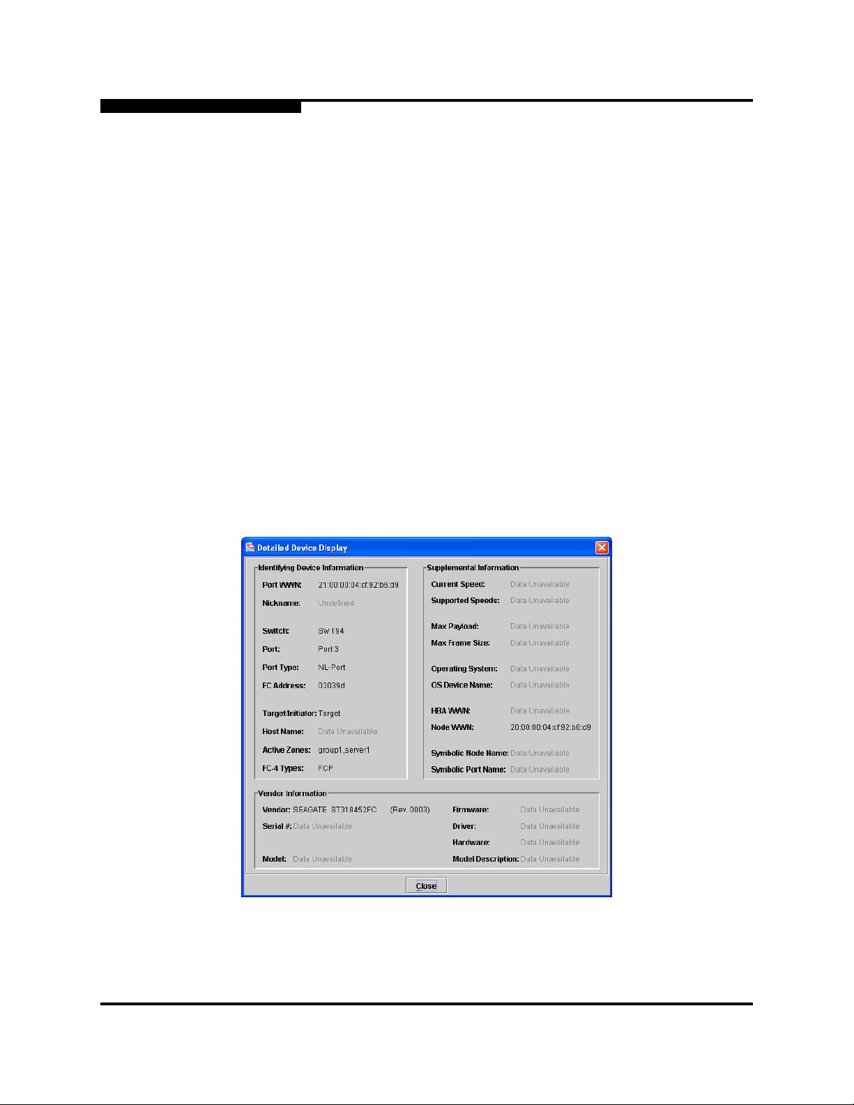
3 – Managing Fabrics
Working with Device Information and Nicknames
3.5.5
Link Data Window
The Link data window displays information about all switch links in the fabric or
selected links. This information includes the switch name, the port number at the
end of each link, and the link status icon. To open the Link data window, click the
Link tab below the data window in the topology display.
3.6
Working with Device Information and Nicknames
SANsurfer Switch Manager enables you to do the following:
Displaying Detailed Device Information
Exporting Device Information to a File
Managing Device Port Nicknames
3.6.1
Displaying Detailed Device Information
0
In addition to the information that is available in the Devices data window, you can
click the (i) in the Details column to display more information shown in
Figure 3-14.
Figure 3-14. Detailed Devices Display Dialog
3-34 59022-11 A
Page 85

0
3.6.2
Exporting Device Information to a File
To save device information to a file, open the topology display and do the
following:
1. Select one or more switches. If no switches are selected, Devices
information is gathered for all switches.
2. Open the Switch menu and select Export Devices Information.
3. In the Save dialog, enter a file name. Select the extension for the type of
output file (CSV or text format) to be saved. CSV files can be opened with
Microsoft Excel or most spreadsheet applications.
4. Click the Save button.
3.6.3
Managing Device Port Nicknames
You can assign a nickname to a device port World Wide Name. A nickname is a
user-definable, meaningful name that can be used in place of the World Wide
Name. Assigning a nickname makes it easier to recognize device ports when
zoning your fabric or when viewing the Devices data window.
3 – Managing Fabrics
Working with Device Information and Nicknames
SANsurfer Switch Manager maintains nicknames in Nicknames.xml, which is
found in your working directory. In addition to creating, editing, and deleting
nicknames, you can also export the nicknames to a file, which can then be
imported into the Nicknames.xml file on other workstations.
3.6.3.1
Creating a Nickname
To create a device port nickname, do the following:
1. Open the File menu and select Nicknames to open the Nicknames dialog.
2. Choose one of the following methods to enter a nickname. A nickname must
start with a letter and can have up to 64 characters. Valid characters include
alphanumeric characters [aA-zZ][0-9] and special symbols [$ _ - ^ ].
Click on a device in the table. Open the Edit menu and select Create
Nickname to open the Add Nickname dialog. In the Add Nickname
dialog, enter a nickname and WWN and click the OK button.
Double-click a cell in the Nicknames column, and enter a new
nickname in the text field. Click the Save button to save the changes
and exit the Nicknames dialog.
You can also create a nickname by double clicking a cell in the Nickname column
of the Devices data window. Refer to ”Devices Data Window” on page 3-32.
59022-11 A 3-35
Page 86

3 – Managing Fabrics
Working with Device Information and Nicknames
3.6.3.2
Editing a Nickname
A nickname must start with a letter and can have up to 64 characters. Valid
characters include alphanumeric characters [aA-zZ][0-9] and special symbols [$ _
- ^ ]. You can access the Edit Nicknames dialog two ways. Choose one of the
following methods to edit a nickname. Click the OK button to save the changes.
In the topology or faceplate display, open the File menu and select
Nicknames to open the Nicknames dialog. The device entries are listed in
table format.
Click on a device entry in the table. Open the Edit menu and select
Edit Nickname to open the Edit Nicknames dialog. Edit the nickname
in the text field. Click the OK button to save the changes.
Double-click a cell in the Nicknames or WWN columns, and edit the
nickname in the text field. Click the OK button to save the changes.
In the topology or faceplate display, click the Devices tab to display the
Devices data window. Double-click a cell in the Nickname column to open
the Edit Nickname dialog. Edit the nickname in the text field. Refer to
”Devices Data Window” on page 3-32.
0
3.6.3.3
Deleting a Nickname
To delete a device port nickname, do the following:
1. Open the File menu and select Nicknames to open the Nicknames dialog.
2. Click a device in the table. Open the Edit menu and select Delete
Nickname.
3.6.3.4
Exporting Nicknames to a File
You can save nicknames to a file. This is useful for distributing nicknames to other
management workstations. To save nicknames to an XML file, do the following:
1. Open the File menu and select Nicknames to open the Nicknames dialog.
2. Open the File menu in the Nicknames dialog, and select Export.
3. Enter a name for the XML nickname file in the Save dialog and click Save.
3-36 59022-11 A
Page 87

0
3.6.3.5
Importing a Nicknames File
Importing a nicknames file copies its contents into and replaces the contents of
the Nicknames.xml file which is used by SANsurfer Switch Manager. To import a
nickname file, do the following:
1. Open the File menu and select Nicknames to open the Nicknames dialog.
2. Open the File menu in the Nicknames dialog, and select Import.
3. Select an XML nickname file in the Open dialog and click Open. When
prompted to overwrite existing nicknames, click Yes.
3.7
Zoning a Fabric
Zoning enables you to divide the ports and devices of the fabric into zones for
more efficient and secure communication among functionally grouped nodes. This
subsection addresses the following topics:
Zoning Concepts
3 – Managing Fabrics
Zoning a Fabric
Using the Zoning Wizard
Managing the Zoning Database
Managing Zone Sets
Managing Zones
Managing Aliases
Merging Fabrics and Zoning
3.7.1
Zoning Concepts
The following zoning concepts provide some context for the zoning tasks
described in this section:
Zones
Aliases
Zone Sets
Zoning Database
Configuring the Zoning Database
59022-11 A 3-37
Page 88

3 – Managing Fabrics
Zoning a Fabric
3.7.1.1
Zones
A zone is a named group of ports or devices that can communicate with each
other. Devices within a zone can only communicate with other devices in the same
zone. A device may participate in more than one zone.
Membership in a zone can be defined by switch domain ID and port number,
device Fibre Channel address (FCID), or device World Wide Name (WWN).
WWN entries define zone membership by the World Wide Name of the
FCID entries define zone membership by the Fibre Channel address of the
0
attached device. With this membership method, you can move WWN
member devices to different switch ports in different zones without having to
edit the member entry as you would with a domain ID/port number member.
Furthermore, unlike FCID members, WWN zone members are not affected
by changes in the fabric that could change the Fibre Channel address of an
attached device.
attached device. With this membership method you can replace a device on
the same port without having to edit the member entry as you would with a
WWN member.
3.7.1.1.1
Soft Zones
Domain ID/Port number entries define zone membership by switch domain
ID and port number. All devices attached to the specified port become
members of the zone. The specified port must be an F_Port or an FL_Port.
Two types of zones are supported:
Soft zone
Hard zone - Access Control List (domain/port member only or it will revert
back to a soft zone when activated)
Soft zoning divides the fabric for purposes of controlling discovery. Devices within
the same soft zone automatically discover and communicate freely with all other
members of the same zone. The soft zone boundary is not secure; traffic across
soft zones can occur if addressed correctly. Soft zones that include members from
multiple switches need not include the ports of the inter-switch links. Soft zone
boundaries yield to ACL zone boundaries. Soft zones can overlap; that is, a
device can participate in more than one soft zone. Zone membership can be
defined by Fibre Channel address, domain ID and port number, World Wide
Name, or a combination. Soft zoning supports all port types.
3-38 59022-11 A
Page 89

0
3.7.1.1.2
Access Control List Hard Zones
Access Control List (ACL) zoning divides the fabric for purposes of controlling
discovery and inbound traffic. ACL zoning is a type of hard zoning that is
hardware enforced. This type of zoning is useful for controlling access to certain
devices without totally isolating them from the fabric. Devices can communicate
with each other and transmit outside the ACL zone, but cannot receive inbound
traffic from outside the zone. The ACL zone boundary is secure against inbound
traffic. ACL zones can overlap; that is, a port can be a member of more than one
ACL zone. ACL zones that include members from multiple switches need not
include the ports of the inter-switch links. ACL zone boundaries supersede soft
zone boundaries. Membership can be defined only by domain ID and port
number. ACL zoning supports all port types. You can have domain/port member in
a configured ACL zone, but it will be converted to a soft zone when activated.
3.7.1.2
Aliases
To make it easier to add a group of ports or devices to one or more zones, you can
create an alias. An alias is a named set of ports or devices that are grouped
together for convenience. Unlike zones, aliases impose no communication
restrictions between its members. You can add an alias to one or more zones.
However, you cannot add a zone to an alias, nor can an alias be a member of
another alias.
3 – Managing Fabrics
Zoning a Fabric
3.7.1.3
Zone Sets
A zone set is a named group of zones. A zone can be a member of more than one
zone set. Each switch in the fabric maintains its own zoning database containing
one or more zone sets. This zoning database resides in non-volatile or permanent
memory and is therefore retained after a reset. Refer to ”Configured Zonesets
Data Window” on page 4-14 for information about displaying the zoning database.
The orphan zone set is created by the application automatically to hold the zones
which are not in any set. The orphan zone set cannot be removed and is not
saved on the switch.
To apply zoning to a fabric, choose a zone set and activate it. When you activate a
zone set, the switch distributes that zone set and its zones, excluding aliases, to
every switch in the fabric. (However, the contents of the aliases are distributed.)
This zone set is known as the active zone set. Refer to ”Active Zone Set Data
Window” on page 3-33 for information about displaying the active zone set.
59022-11 A 3-39
Page 90

3 – Managing Fabrics
Zoning a Fabric
3.7.1.4
Zoning Database
Each switch has its own zoning database. The zoning database is made up of all
aliases, zones, and zone sets that have been created on the switch or received
from other switches. The switch maintains two copies of the inactive zoning
database: one copy is maintained in temporary memory for editing purposes; the
second copy is maintained in permanent memory. Zoning database edits are
made on an individual switch basis and are not propagated to other switches in
the fabric when saved.
There are two configuration parameters that affect the zoning database: Interop
Auto Save and Default Visibility. The Auto Save parameter determines whether
changes to the active zone set that a switch receives from another switch in the
fabric will be saved to permanent memory on that switch. The Default Visibility
parameter permits or prohibits communication among ports/devices when there is
no active zone set. Refer to ”Configuring the Zoning Database” on page 3-44 for
information about zoning configuration.
The following zoning limits will be enforced during the configuration of zoning and
during a zoning database merge from the fabric:
0
MaxZoneSets is 256. The maximum number of zone sets that can be
configured on the switch.
MaxZones is 2000. The maximum number of zones that can be configured
on the switch.
MaxAliases is 2500. The maximum number of aliases that can be
configured on the switch.
MaxTotalMembers is 10,000. The maximum number of total zone and alias
members that can be configured on the switch. Aliases are considered zone
members since they can be added to a zone just like a normal zone
member.
MaxZonesInZoneSets is 1000. The maximum number of zone linkages to
zonesets that can be configured on the switch. Every time a zone is added
to a zoneset this constitutes a linkage.
MaxMembersPerZone is 2000. The maximum number of zone members
that can be added to any zone on the switch. Aliases are considered zone
members when added to a zone.
MaxMembersPerAlias is 2000. The maximum number of zone members
that can be added to any alias on the switch.
3-40 59022-11 A
Page 91

0
3.7.2
Using the Zoning Wizard
The Zoning Wizard is a series of dialogs that leads you through the process of
zoning a fabric. To open the Zoning Wizard, open the Wizards menu in the
faceplate display, and select Zoning Wizard.
The Zoning Wizard helps you zone the two most typical reasons for zoning:
Zoning Windows servers storage
Assign storage to servers.
To solve these problems, there must be at least one target and at least one
initiator in the name server. Windows servers do not share devices well, but
sometimes they must share devices, such as a tape drive. The wizard helps you
define which devices are sharable and which ones are not. Once a device is in a
Windows group, it can no longer be in any other group.
3.7.3
Managing the Zoning Database
3 – Managing Fabrics
Zoning a Fabric
Managing the zoning database consists of the following:
Editing the Zoning Database
Configuring the Zoning Database
Saving the Zoning Database to a File
Restoring the Zoning Database from a File
Restoring the Default Zoning Database
Removing All Zoning Definitions
59022-11 A 3-41
Page 92

3 – Managing Fabrics
Zoning a Fabric
3.7.3.1
Editing the Zoning Database
To edit the zoning database for a particular switch, open the Zoning menu from
the faceplate display and select Edit Zoning to open the Edit Zoning dialog
shown in Figure 3-15. Changes can only be made to inactive zone sets, which are
stored in flash (non-volatile) memory and retained after resetting a switch.
0
Port/Device
Tree
Zone Sets
Tree
Figure 3-15. Edit Zoning Dialog
To apply zoning to a fabric, choose a zone set and activate it. When you activate a
zone set, the switch distributes that zone set and its zones, excluding aliases, to
every switch in the fabric. This zone set is known as the active zone set.
You can not edit an active zone set on a switch. You must configure an inactive
zone set to your needs and then activate that updated zone set to apply the
changes to the fabric. When you activate a zone set, the switch distributes that
zone set to the temporary zoning database on every switch in the fabric. However,
in addition to the merged active zone set, each switch maintains its own original
zone set in its zoning database. Only one zone set can be active at one time.
Note: If the Interop Auto Save parameter is enabled on the Zoning
Configuration dialog, then every time the active zone set changes, the
switch will copy it into an inactive zone set stored on the switch. You
can edit this copy of the active zone set stored on the switch, and
activate the updated copy to conveniently apply the changes to the
active zone set. The edited copy then becomes the active zone set.
3-42 59022-11 A
Page 93

0
3 – Managing Fabrics
Zoning a Fabric
The Edit Zoning dialog has a Zone Sets tree on the left and a Port/Device (or
members) tree on the right. Both trees use display conventions similar to the
fabric tree for expanding and contracting zone sets, zones, and ports. An
expanded port shows the port Fibre Channel address; an expanded address
shows the port World Wide Name. You can select zone sets, zones, and ports in
the following ways:
Click a zone, zone set, or port icon.
Right-click to select a zone set or zone, and open the corresponding popup
menu.
Hold down the Shift key while clicking several consecutive icons.
Hold down the Control key while clicking several non-consecutive icons.
Using tool bar buttons, popup menus, or a drag-and-drop method, you can create
and manage zone sets and zones in the zoning database. Ta bl e 3-4 describes the
zoning tool bar operations.
Use the Edit Zoning dialog to define zoning changes, and click the Apply button
to open the Error Check dialog. Click the Error Check button to have SANsurfer
Switch Manager check for zoning conflicts, such as empty zones, aliases, or zone
sets, and ACL zones with non-domain ID/port number membership. Click the
Save Zoning button to implement the changes. Click the Close button to close
the Error Check dialog. On the Edit Zoning dialog, click the Close button to close
the Edit Zoning dialog.
Table 3-4. Edit Zoning Dialog Tool Bar Buttons and Icons
Tool Bar Button Description
Create Zone Set button - create a new zone set
Create Zone button - create a new zone
Create Alias button - create another name for a set of objects
Add Member button - adds selected port/device to a zone
Remove Member button - delete the selected zone from a zone
set, or delete the selected port/device from a zone
59022-11 A 3-43
Page 94

3 – Managing Fabrics
Zoning a Fabric
Tool Bar Button Description
0
Table 3-4. Edit Zoning Dialog Tool Bar Buttons and Icons (Continued)
Switch port icon – not logged in
Switch port icon – logged in
NL_Port (loop) device icon – logged in to fabric
NL_Port (loop) device icon – not logged in to fabric
N_Port device icon – logged in to fabric
N_Port device icon – not logged in to fabric
3.7.3.2
Configuring the Zoning Database
Use the Zoning Config dialog to change the Auto Save, Default Visibility, and
Discard Inactive configuration parameters. In the faceplate display, open the
Zoning menu and select Edit Zoning Config to open the Zoning Config dialog
shown in Figure 3-16. After making changes, click the OK button to put the new
values into effect.
Figure 3-16. Zoning Config Dialog
3-44 59022-11 A
Page 95

0
3.7.3.2.1
Interop Auto Save
The Interop Auto Save parameter determines whether changes to the active zone
set that a switch receives from other switches in the fabric will be saved to the
zoning database on that switch. Changes are saved when an updated zone set is
activated. Zoning changes are always saved to temporary memory. However, if
Interop Auto Save is enabled, the switch firmware saves changes to the active
zone set in temporary memory and to the zoning database. If Interop Auto Save is
disabled, changes to the active zone set are stored only in temporary memory
which is cleared when the switch is reset.
Note: Disabling the Interop Auto Save parameter can be useful to prevent
3 – Managing Fabrics
Zoning a Fabric
the propagation of zoning information when experimenting with
different zoning schemes. However, leaving the Interop Auto Save
parameter disabled can disrupt device configurations should a switch
have to be reset. For this reason, the Interop Auto Save parameter
should be enabled in a production environment.
3.7.3.2.2
Default Visibility
Default visibility determines the level of communication that is permitted among
ports/devices when there is no active zone set. The default visibility parameter
can be set differently on each switch. When default visibility is enabled (ALL) on a
switch, all ports/devices on the switch can communicate with all ports/devices on
switches that also have default visibility enabled. When Default Visibility is
disabled (NONE), none of the ports/devices on that switch can communicate with
any other port/device in the fabric.
3.7.3.2.3
Discard Inactive
The Discard Inactive parameter automatically removes inactive zones and zone
sets when a zoneset is activated or deactivated from a remote switch.
3.7.3.3
Saving the Zoning Database to a File
You can save the zoning database to an XML file. You can later reload this zoning
database on the same switch or another switch. To save a zoning database to a
file, do the following:
1. In the faceplate display, open the Zoning menu, and select Edit Zoning.
2. In the Edit Zoning dialog, open the File menu and select Save As.
3. In the Save dialog, enter a file name for the database file.
4. Click the Save button to save the zoning file.
59022-11 A 3-45
Page 96

3 – Managing Fabrics
Zoning a Fabric
3.7.3.4
Restoring the Zoning Database from a File
0
CAUTION!
Do the following to restore the zoning database from a file to a switch:
1. In the faceplate display, open the Zoning menu and select Edit Zoning to
open the Edit Zoning window.
2. Open the File menu and select Open File. A popup window will prompt you
to select an XML zoning database file.
3. Select a file and click Open.
3.7.3.5
Restoring the zoning database from a file will replace the current
zoning database on the switch.
Restoring the Default Zoning Database
Restoring the default zoning clears the switch of all zoning definitions.
CAUTION!
To restore the default zoning for a switch:
1. In the faceplate display, open the Zoning menu and select Restore Default
Zoning.
This command will deactivate the active zone set.
2. Click the OK button to confirm that you want to restore default zoning and
save changes to the zoning database.
3.7.3.6
Removing All Zoning Definitions
To clear all zone and zone set definitions from the zoning database, choose one of
the following:
Open the Edit menu and select Clear Zoning. In the Removes All dialog,
click the Yes button to confirm that you want to delete all zones and zone
sets.
Right-click the Zone Sets heading at the top of the Zone Sets tree, and
select Clear Zoning from the popup menu. Click the Yes button to confirm
that you want to delete all zone sets and zones.
3-46 59022-11 A
Page 97

0
3.7.4
Managing Zone Sets
Zoning a fabric involves creating a zone set, creating zones as zone set members,
then adding devices as zone members. The zoning database supports multiple
zone sets to serve the different security and access needs of your storage area
network, but only one zone set can be active at one time. Managing zone sets
consists of the following tasks:
Creating a Zone Set
Activating and Deactivating a Zone Set
Copying a Zone to a Zone Set
Removing a Zone from a Zone Set or from All Zone Sets
Removing a Zone Set
Note: Changes that you make to the zoning database are limited to the
managed switch and do not propagate to the rest of the fabric. To
distribute changes to configured zone sets fabric wide, you must edit
the zoning databases on the individual switches.
3 – Managing Fabrics
Zoning a Fabric
3.7.4.1
Creating a Zone Set
To create a zone set, do the following:
1. Open the Zoning menu, and select Edit Zoning to open the Edit Zoning
dialog.
2. Open the Edit menu, and select Create Zone Set to open the Create Zone
Set dialog.
3. Enter a name for the zone set, and click the OK button. The new zone set
name is displayed in the Zone Sets dialog. A zone set name must begin with
a letter and be no longer than 64 characters. Valid characters are 0-9, A-Z,
a-z, _, -, ^, and $.
59022-11 A 3-47
Page 98

3 – Managing Fabrics
Zoning a Fabric
4. To create new zones in a zone set, do one of the following:
Right-click a zone set and select Create A Zone from the popup menu.
In the Create a Zone dialog, enter a name for the new zone, and click
the OK button. The new zone name is displayed in the Zone Sets
dialog.
Select a zone set in the zone sets tree, and click the Zone button in the
Zoning toolbar. In the Create a Zone dialog, enter a name for the new
zone, and click the OK button. The new zone name is displayed in the
Zone Sets dialog.
Copy an existing zone by dragging a zone into the new zone set. Refer
to ”Copying a Zone to a Zone Set” on page 3-48.
5. Click the Apply button to save changes to the zoning database.
3.7.4.2
Activating and Deactivating a Zone Set
You must activate a zone set to apply its zoning definitions to the fabric. Only one
zone set can be active at one time. When you activate a zone set, the switch
distributes that zone set to the temporary zoning database on every switch in the
fabric.
0
The purpose of the deactivate function is to suspend all fabric zoning which
results in free communication fabric wide or no communication depending on the
default visibility setting. Refer to ”Default Visibility” on page 3-45 for more
information. It is not necessary to deactivate the active zone set before activating
a new one.
To activate a zone set, open the Zoning menu and select Activate Zone Set
to open the Activate Zone Set dialog. Select a zone set from the Select Zone
Set pull-down menu, and click the Activate button.
To deactivate the active zone set, open the Zoning menu, select Deactivate
Zone Set. Acknowledge the warning about traffic disruption, and click the
Yes button to confirm that you want to deactivate the active zone set.
3.7.4.3
Copying a Zone to a Zone Set
To copy an existing zone and its membership from one zone set to another, select
the zone and drag it to the chosen zone set. Click the Apply button to save
changes to the zoning database.
3-48 59022-11 A
Page 99

0
3.7.4.4
Removing a Zone from a Zone Set or from All Zone Sets
You can remove a zone from a zone set or from all zone sets in the database.
1. In the faceplate display, open the Zoning menu and select Edit Zoning to
open the Edit Zoning dialog.
2. In the Zone Sets tree, select the zone(s) to be removed.
3. Open the Edit menu, and select Remove to remove the zone from the zone
set, or select Remove from All Zones to remove the zone from all zone
sets.
4. Click the Apply button to save changes to the zoning database.
Alternatively, you may use shortcut menus to remove a zone from a zone set or
from all zone sets in the database.
3.7.4.5
Removing a Zone Set
Removing a zone set from the database affects the member zones in the following
ways.
3 – Managing Fabrics
Zoning a Fabric
Member zones that are members of other zone sets are not affected.
Member zones that are not members of other zone sets become members
of the orphan zone set, which cannot be removed. The orphan zone set is
not saved on the switch.
To delete a zone set from the database, do the following:
1. In the faceplate display, open the Zoning menu and select Edit Zoning to
open the Edit Zoning dialog.
2. In the Zone Sets tree, select the zone set to be removed.
3. Open the Edit menu, and select Remove to remove the zone set.
4. Click the Apply button to save changes to the zoning database.
Alternatively, you may use shortcut menus to remove a zone set from the
database.
59022-11 A 3-49
Page 100

3 – Managing Fabrics
Zoning a Fabric
3.7.5
Managing Zones
Managing zones involves the following:
Creating a Zone in a Zone Set
Adding Zone Members
Renaming a Zone or a Zone Set
Removing a Zone Member
Removing a Zone from a Zone Set
Removing a Zone from All Zone Sets
Changing Zone Types
Note: Changes that you make to the zoning database are limited to the
0
managed switch and do not propagate to the rest of the fabric. To
distribute changes to configured zone sets fabric wide, you must edit
the zoning databases on the individual switches.
3.7.5.1
Creating a Zone in a Zone Set
When a zone is created, its zone type is soft. To change the zone type to a hard
zone, refer to ”Changing Zone Types” on page 3-53 for more information. Refer to
”Zones” on page 3-38 for information on zone types (soft and hard). To create a
zone in a zone set, do the following:
1. Open the Zoning menu, and select Edit Zoning to open the Edit Zoning
dialog.
2. Select a zone set.
3. Open the Edit menu and select Create a Zone.
4. In the Create a Zone dialog, enter a name for the new zone, and click the
OK button. The new zone name is displayed in the Zone Sets dialog. A zone
name must begin with a letter and be no longer than 64 characters. Valid
characters are 0-9, A-Z, a-z, _, ^, $, and -.
Note: If you enter the name of a zone that already exists in the
database, the SANsurfer Switch Manager application will ask if
you would like to add that zone and its membership to the zone
set.
3-50 59022-11 A
 Loading...