

Page 1

User’s Guide
Enterprise Fabric Suite
5800V Series Fibre Channel Switches
Firmware Version 8.0
59266-01 B
Page 2

User’s Guide Enterprise Fabric Suite
5800V Series Fibre Channel Switches
Information furnished in this manual is believed to be accurate and reliable. However, QLogic Corporation assumes no
responsibility for its use, nor for any infringements of patents or other rights of third parties which may result from its
use. QLogic Corporation reserves the right to change product specifications at any time without notice. Applications
described in this document for any of these products are for illustrative purposes only. QLogic Corporation makes no
representation nor warranty that such applications are suitable for the specified use without further testing or
modification. QLogic Corporation assumes no responsibility for any errors that may appear in this document.
This switch is covered by one or more of the following patents: 6697359; other patents pending.
Document Revision History
Release, Revision A, October 2008
Release, Revision B, November 2011
Changes Pages Affected
Added Transparent Router Support 2-9
Added Internet Key Exchange Support 5-40
ii 59266-01 B
Page 3

Content s
Preface
Intended Audience . . . . . . . . . . . . . . . . . . . . . . . . . . . . . . . . . . . . . . . . . . . . xvi
Related Materials . . . . . . . . . . . . . . . . . . . . . . . . . . . . . . . . . . . . . . . . . . . . . xvi
Documentation Conventions . . . . . . . . . . . . . . . . . . . . . . . . . . . . . . . . . . . . xvi
JDOM License . . . . . . . . . . . . . . . . . . . . . . . . . . . . . . . . . . . . . . . . . . . . . . . xvii
Technical Support. . . . . . . . . . . . . . . . . . . . . . . . . . . . . . . . . . . . . . . . . . . . . xix
Training . . . . . . . . . . . . . . . . . . . . . . . . . . . . . . . . . . . . . . . . . . . . . . . . xix
Contact Information. . . . . . . . . . . . . . . . . . . . . . . . . . . . . . . . . . . . . . . xix
Knowledge Database . . . . . . . . . . . . . . . . . . . . . . . . . . . . . . . . . . . . . xx
1 Using Enterprise Fabric Suite
Workstation Requirements. . . . . . . . . . . . . . . . . . . . . . . . . . . . . . . . . . . . . . 1-1
Installing Enterprise Fabric Suite . . . . . . . . . . . . . . . . . . . . . . . . . . . . . . . . . 1-2
Starting Enterprise Fabric Suite . . . . . . . . . . . . . . . . . . . . . . . . . . . . . . . . . . 1-3
Exiting Enterprise Fabric Suite. . . . . . . . . . . . . . . . . . . . . . . . . . . . . . . . . . . 1-6
Uninstalling Enterprise Fabric Suite. . . . . . . . . . . . . . . . . . . . . . . . . . . . . . . 1-7
Changing the Encryption Key for the Default Fabric View File. . . . . . . . . . . 1-8
Saving and Opening Fabric View Files . . . . . . . . . . . . . . . . . . . . . . . . . . . . 1-8
Setting Enterprise Fabric Suite Preferences . . . . . . . . . . . . . . . . . . . . . . . . 1-9
Using Online Help . . . . . . . . . . . . . . . . . . . . . . . . . . . . . . . . . . . . . . . . . . . . 1-11
Viewing Software Version and Copyright Information . . . . . . . . . . . . . . . . . 1-11
Enterprise Fabric Suite User Interface. . . . . . . . . . . . . . . . . . . . . . . . . . . . . 1-12
Fabric Tree . . . . . . . . . . . . . . . . . . . . . . . . . . . . . . . . . . . . . . . . . . . . . 1-14
Graphic Window . . . . . . . . . . . . . . . . . . . . . . . . . . . . . . . . . . . . . . . . . 1-15
Data Windows and Tabs . . . . . . . . . . . . . . . . . . . . . . . . . . . . . . . . . . . 1-15
Alerts Panel. . . . . . . . . . . . . . . . . . . . . . . . . . . . . . . . . . . . . . . . . . . . . 1-16
Menus . . . . . . . . . . . . . . . . . . . . . . . . . . . . . . . . . . . . . . . . . . . . . . . . . 1-17
Topology Display Menu . . . . . . . . . . . . . . . . . . . . . . . . . . . . . . . 1-17
Faceplate Display Menu. . . . . . . . . . . . . . . . . . . . . . . . . . . . . . . 1-19
Menu Shortcut Keys . . . . . . . . . . . . . . . . . . . . . . . . . . . . . . . . . . 1-22
Shortcut Menus . . . . . . . . . . . . . . . . . . . . . . . . . . . . . . . . . . . . . 1-23
Tool Bar. . . . . . . . . . . . . . . . . . . . . . . . . . . . . . . . . . . . . . . . . . . . . . . . 1-24
Working with Switches and Links . . . . . . . . . . . . . . . . . . . . . . . . . . . . 1-24
59266-01 B iii
Page 4

User’s Guide Enterprise Fabric Suite
5800V Series Fibre Channel Switches
Working with Ports. . . . . . . . . . . . . . . . . . . . . . . . . . . . . . . . . . . . . . . . 1-26
2 Managing Fabrics
Fabric Firmware and Software Versions . . . . . . . . . . . . . . . . . . . . . . . . . . . 2-1
Saving a Version Snapshot . . . . . . . . . . . . . . . . . . . . . . . . . . . . . . . . . 2-1
Viewing and Comparing Version Snapshots . . . . . . . . . . . . . . . . . . . . 2-1
Exporting Version Snapshots to a File. . . . . . . . . . . . . . . . . . . . . . . . . 2-2
Managing the Fabric Database . . . . . . . . . . . . . . . . . . . . . . . . . . . . . . . . . . 2-3
Adding a Fabric . . . . . . . . . . . . . . . . . . . . . . . . . . . . . . . . . . . . . . . . . . 2-3
Removing a Fabric . . . . . . . . . . . . . . . . . . . . . . . . . . . . . . . . . . . . . . . 2-4
Opening a Fabric View File . . . . . . . . . . . . . . . . . . . . . . . . . . . . . . . . . 2-4
Saving a Fabric View File . . . . . . . . . . . . . . . . . . . . . . . . . . . . . . . . . . 2-4
Rediscovering a Fabric . . . . . . . . . . . . . . . . . . . . . . . . . . . . . . . . . . . . 2-5
Deleting Switches and Links . . . . . . . . . . . . . . . . . . . . . . . . . . . . . . . . 2-5
Adding a New Switch to a Fabric . . . . . . . . . . . . . . . . . . . . . . . . . . . . . . . . . 2-5
Replacing a Failed Switch . . . . . . . . . . . . . . . . . . . . . . . . . . . . . . . . . . . . . . 2-6
Displaying Fabric Information. . . . . . . . . . . . . . . . . . . . . . . . . . . . . . . . . . . . 2-7
Link Data Window . . . . . . . . . . . . . . . . . . . . . . . . . . . . . . . . . . . . . . . . 2-7
Displaying Fabric Status . . . . . . . . . . . . . . . . . . . . . . . . . . . . . . . . . . . 2-8
Transparent Router . . . . . . . . . . . . . . . . . . . . . . . . . . . . . . . . . . . . . . . . . . . 2-9
TR Mapping Manager Dialog Box . . . . . . . . . . . . . . . . . . . . . . . . . . . . 2-11
Removing an Inter-Fabric Route . . . . . . . . . . . . . . . . . . . . . . . . 2-13
Add TR Mapping Dialog Box. . . . . . . . . . . . . . . . . . . . . . . . . . . . . . . . 2-13
Mapping a New Inter-Fabric Zone . . . . . . . . . . . . . . . . . . . . . . . 2-14
Remote Fabric Zoning Dialog Box. . . . . . . . . . . . . . . . . . . . . . . . . . . . 2-16
Transparent Routes Data Window . . . . . . . . . . . . . . . . . . . . . . . . . . . . . . . . 2-19
Event Browser. . . . . . . . . . . . . . . . . . . . . . . . . . . . . . . . . . . . . . . . . . . 2-21
Filtering the Event Browser . . . . . . . . . . . . . . . . . . . . . . . . . . . . 2-22
Sorting the Event Browser . . . . . . . . . . . . . . . . . . . . . . . . . . . . . 2-23
Saving the Event Browser to a File . . . . . . . . . . . . . . . . . . . . . . 2-23
Verifying Fibre Channel Connections. . . . . . . . . . . . . . . . . . . . . . . . . . . . . . 2-24
FC Ping Dialog Box. . . . . . . . . . . . . . . . . . . . . . . . . . . . . . . . . . . . . . . 2-24
FC Traceroute Dialog Box. . . . . . . . . . . . . . . . . . . . . . . . . . . . . . . . . . 2-25
Device information and nicknames . . . . . . . . . . . . . . . . . . . . . . . . . . . . . . . 2-26
Devices Data Window . . . . . . . . . . . . . . . . . . . . . . . . . . . . . . . . . . . . . 2-26
iv 59266-01 B
Page 5

Managing Device Port Nicknames . . . . . . . . . . . . . . . . . . . . . . . . . . . 2-28
Creating a Nickname . . . . . . . . . . . . . . . . . . . . . . . . . . . . . . . . . 2-28
Editing a Nickname. . . . . . . . . . . . . . . . . . . . . . . . . . . . . . . . . . . 2-29
Deleting a Nickname . . . . . . . . . . . . . . . . . . . . . . . . . . . . . . . . . 2-29
Exporting Nicknames to a File . . . . . . . . . . . . . . . . . . . . . . . . . . 2-29
Importing a Nicknames File . . . . . . . . . . . . . . . . . . . . . . . . . . . . 2-29
Fabric Services. . . . . . . . . . . . . . . . . . . . . . . . . . . . . . . . . . . . . . . . . . . . . . . 2-30
Enabling SNMP Configuration. . . . . . . . . . . . . . . . . . . . . . . . . . . . . . . 2-30
Enabling In-band Management. . . . . . . . . . . . . . . . . . . . . . . . . . . . . . 2-31
3 Managing Fabric Security
Connection Security. . . . . . . . . . . . . . . . . . . . . . . . . . . . . . . . . . . . . . . . . . . 3-1
User Account Security . . . . . . . . . . . . . . . . . . . . . . . . . . . . . . . . . . . . . . . . . 3-2
Port security . . . . . . . . . . . . . . . . . . . . . . . . . . . . . . . . . . . . . . . . . . . . . . . . . 3-2
Device Security . . . . . . . . . . . . . . . . . . . . . . . . . . . . . . . . . . . . . . . . . . . . . . 3-3
Managing the Security Database . . . . . . . . . . . . . . . . . . . . . . . . . . . . 3-5
Viewing the Device Security Database. . . . . . . . . . . . . . . . . . . . 3-5
Configuring the Security Data Base . . . . . . . . . . . . . . . . . . . . . . 3-6
Saving the Security Database to a File. . . . . . . . . . . . . . . . . . . . 3-7
Restoring the Security Database from a File . . . . . . . . . . . . . . . 3-7
Resetting the Security Database . . . . . . . . . . . . . . . . . . . . . . . . 3-8
Managing Security Sets. . . . . . . . . . . . . . . . . . . . . . . . . . . . . . . . . . . . 3-8
Creating a Security Set. . . . . . . . . . . . . . . . . . . . . . . . . . . . . . . . 3-8
Removing a Security Set . . . . . . . . . . . . . . . . . . . . . . . . . . . . . . 3-9
Renaming a Security Set . . . . . . . . . . . . . . . . . . . . . . . . . . . . . . 3-9
Adding an Existing Group to a Security Set . . . . . . . . . . . . . . . . 3-10
Removing a Group from a Security Set . . . . . . . . . . . . . . . . . . . 3-10
Removing a Group from all Security Sets. . . . . . . . . . . . . . . . . . 3-10
Activating a Security Set. . . . . . . . . . . . . . . . . . . . . . . . . . . . . . . 3-11
Deactivating a Security Set . . . . . . . . . . . . . . . . . . . . . . . . . . . . 3-11
Managing Security Groups and Members. . . . . . . . . . . . . . . . . . . . . . 3-11
Creating a Security Group . . . . . . . . . . . . . . . . . . . . . . . . . . . . . 3-11
Creating a Security Group Member . . . . . . . . . . . . . . . . . . . . . . 3-12
Modifying a Security Group Member . . . . . . . . . . . . . . . . . . . . . 3-14
Removing a Member from a Group . . . . . . . . . . . . . . . . . . . . . . 3-14
Using RADIUS Servers . . . . . . . . . . . . . . . . . . . . . . . . . . . . . . . . . . . . 3-15
Adding a RADIUS Server . . . . . . . . . . . . . . . . . . . . . . . . . . . . . . 3-15
Removing a RADIUS Server . . . . . . . . . . . . . . . . . . . . . . . . . . . 3-17
Editing RADIUS Server Information . . . . . . . . . . . . . . . . . . . . . . 3-18
Modifying Authentication Order RADIUS Server Information. . . 3-19
User’s Guide Enterprise Fabric Suite
5800V Series Fibre Channel Switches
59266-01 B v
Page 6

User’s Guide Enterprise Fabric Suite
5800V Series Fibre Channel Switches
4 Managing Fabric Zoning
Zoning Concepts . . . . . . . . . . . . . . . . . . . . . . . . . . . . . . . . . . . . . . . . . . . . . 4-1
Zones. . . . . . . . . . . . . . . . . . . . . . . . . . . . . . . . . . . . . . . . . . . . . . . . . . 4-1
Aliases. . . . . . . . . . . . . . . . . . . . . . . . . . . . . . . . . . . . . . . . . . . . . . . . . 4-2
Zone Sets . . . . . . . . . . . . . . . . . . . . . . . . . . . . . . . . . . . . . . . . . . . . . . 4-2
Zoning Database. . . . . . . . . . . . . . . . . . . . . . . . . . . . . . . . . . . . . . . . . 4-3
Using the Zoning Wizard . . . . . . . . . . . . . . . . . . . . . . . . . . . . . . . . . . . . . . . 4-3
Managing the Zoning Database. . . . . . . . . . . . . . . . . . . . . . . . . . . . . . . . . . 4-3
Viewing Zoning Limits and Properties. . . . . . . . . . . . . . . . . . . . . . . . . 4-3
Viewing Active and Configured Zone Set Information. . . . . . . . . . . . . 4-4
Editing the Zoning Database. . . . . . . . . . . . . . . . . . . . . . . . . . . . . . . . 4-6
Configuring the Zoning Database . . . . . . . . . . . . . . . . . . . . . . . . . . . . 4-9
Merge Auto Save . . . . . . . . . . . . . . . . . . . . . . . . . . . . . . . . . . . . 4-10
Default Zone. . . . . . . . . . . . . . . . . . . . . . . . . . . . . . . . . . . . . . . . 4-10
Discard Inactive . . . . . . . . . . . . . . . . . . . . . . . . . . . . . . . . . . . . . 4-10
Saving and Restoring the Zoning Database to a File . . . . . . . . . . . . . 4-10
Saving the Zoning Database to a File. . . . . . . . . . . . . . . . . . . . . 4-10
Restoring the Zoning Database from a File . . . . . . . . . . . . . . . . 4-11
Restoring the Default Zoning Database . . . . . . . . . . . . . . . . . . . 4-11
Removing All Zone and Zone Set Definitions. . . . . . . . . . . . . . . 4-12
Merging Fabrics and Zoning. . . . . . . . . . . . . . . . . . . . . . . . . . . . . . . . . . . . . 4-12
Zone Merge Failure. . . . . . . . . . . . . . . . . . . . . . . . . . . . . . . . . . . . . . . 4-12
Zone Merge Failure Recovery. . . . . . . . . . . . . . . . . . . . . . . . . . . . . . . 4-13
Resolving Active, Configured, and Merged Zone Sets . . . . . . . . . . . . 4-13
Managing Zone Sets . . . . . . . . . . . . . . . . . . . . . . . . . . . . . . . . . . . . . . . . . . 4-14
Creating a Zone Set . . . . . . . . . . . . . . . . . . . . . . . . . . . . . . . . . . . . . . 4-14
Activating and Deactivating a Zone Set. . . . . . . . . . . . . . . . . . . . . . . . 4-15
Renaming a Zone Set . . . . . . . . . . . . . . . . . . . . . . . . . . . . . . . . . . . . . 4-15
Removing a Zone Set . . . . . . . . . . . . . . . . . . . . . . . . . . . . . . . . . . . . . 4-16
Managing Zones. . . . . . . . . . . . . . . . . . . . . . . . . . . . . . . . . . . . . . . . . . . . . . 4-17
Creating a Zone in a Zone Set . . . . . . . . . . . . . . . . . . . . . . . . . . . . . . 4-17
Copying a Zone to a Zone Set. . . . . . . . . . . . . . . . . . . . . . . . . . . . . . . 4-18
Adding Zone Members . . . . . . . . . . . . . . . . . . . . . . . . . . . . . . . . . . . . 4-19
Renaming a Zone . . . . . . . . . . . . . . . . . . . . . . . . . . . . . . . . . . . . . . . . 4-20
Removing a Zone Member . . . . . . . . . . . . . . . . . . . . . . . . . . . . . . . . . 4-21
Removing a Zone from a Zone Set . . . . . . . . . . . . . . . . . . . . . . . . . . . 4-22
Removing a Zone from All Zone Sets . . . . . . . . . . . . . . . . . . . . . . . . . 4-22
Managing Aliases. . . . . . . . . . . . . . . . . . . . . . . . . . . . . . . . . . . . . . . . . . . . . 4-23
Creating an Alias. . . . . . . . . . . . . . . . . . . . . . . . . . . . . . . . . . . . . . . . . 4-23
vi 59266-01 B
Page 7

Adding a Member to an Alias . . . . . . . . . . . . . . . . . . . . . . . . . . . . . . . 4-24
Removing an Alias from All Zones . . . . . . . . . . . . . . . . . . . . . . . . . . . 4-25
5 Managing Switches
Managing User Accounts. . . . . . . . . . . . . . . . . . . . . . . . . . . . . . . . . . . . . . . 5-1
Creating User Accounts. . . . . . . . . . . . . . . . . . . . . . . . . . . . . . . . . . . . 5-2
Removing a User Account. . . . . . . . . . . . . . . . . . . . . . . . . . . . . . . . . . 5-3
Changing a User Account Password. . . . . . . . . . . . . . . . . . . . . . . . . . 5-4
Modifying a User Account . . . . . . . . . . . . . . . . . . . . . . . . . . . . . . . . . . 5-5
Viewing Switch Information . . . . . . . . . . . . . . . . . . . . . . . . . . . . . . . . . . . . . 5-6
Switch data window. . . . . . . . . . . . . . . . . . . . . . . . . . . . . . . . . . . . . . . 5-7
Stack Links data window . . . . . . . . . . . . . . . . . . . . . . . . . . . . . . . . . . . 5-13
Configuring Port Threshold Alarms . . . . . . . . . . . . . . . . . . . . . . . . . . . . . . . 5-14
Paging a Switch . . . . . . . . . . . . . . . . . . . . . . . . . . . . . . . . . . . . . . . . . . . . . . 5-16
Setting the Date/time and Enabling NTP Client . . . . . . . . . . . . . . . . . . . . . . 5-17
Resetting a Switch . . . . . . . . . . . . . . . . . . . . . . . . . . . . . . . . . . . . . . . . . . . . 5-18
Configuring a Switch . . . . . . . . . . . . . . . . . . . . . . . . . . . . . . . . . . . . . . . . . . 5-19
Using the Configuration Wizard. . . . . . . . . . . . . . . . . . . . . . . . . . . . . . 5-19
Switch Properties. . . . . . . . . . . . . . . . . . . . . . . . . . . . . . . . . . . . . . . . . 5-19
Domain ID and Domain ID Lock. . . . . . . . . . . . . . . . . . . . . . . . . 5-20
Syslog. . . . . . . . . . . . . . . . . . . . . . . . . . . . . . . . . . . . . . . . . . . . . 5-21
Symbolic Name . . . . . . . . . . . . . . . . . . . . . . . . . . . . . . . . . . . . . 5-21
Switch Administrative States. . . . . . . . . . . . . . . . . . . . . . . . . . . . 5-21
Broadcast Support . . . . . . . . . . . . . . . . . . . . . . . . . . . . . . . . . . . 5-22
In-band Management . . . . . . . . . . . . . . . . . . . . . . . . . . . . . . . . . 5-22
Fabric Device Management Interface. . . . . . . . . . . . . . . . . . . . . 5-22
Advanced Switch Properties (Timeout Values) . . . . . . . . . . . . . . . . . . 5-23
Managing System Services. . . . . . . . . . . . . . . . . . . . . . . . . . . . . . . . . 5-24
Managing Switch Stacks . . . . . . . . . . . . . . . . . . . . . . . . . . . . . . . . . . . . . . . 5-26
Configuring Switches in a Stack . . . . . . . . . . . . . . . . . . . . . . . . . . . . . 5-27
Security Consistency Checklist . . . . . . . . . . . . . . . . . . . . . . . . . . . . . . 5-28
Configuring the Network. . . . . . . . . . . . . . . . . . . . . . . . . . . . . . . . . . . . . . . . 5-29
Network IP Configuration. . . . . . . . . . . . . . . . . . . . . . . . . . . . . . . . . . . 5-30
Network DNS Configuration . . . . . . . . . . . . . . . . . . . . . . . . . . . . . . . . 5-32
Network IP Security. . . . . . . . . . . . . . . . . . . . . . . . . . . . . . . . . . . . . . . 5-33
Security Policies . . . . . . . . . . . . . . . . . . . . . . . . . . . . . . . . . . . . . 5-35
Security Associations . . . . . . . . . . . . . . . . . . . . . . . . . . . . . . . . . 5-38
IPsecIKE Properties . . . . . . . . . . . . . . . . . . . . . . . . . . . . . . . . . . 5-40
Configuring IKE Policies. . . . . . . . . . . . . . . . . . . . . . . . . . . . . . . 5-45
User’s Guide Enterprise Fabric Suite
5800V Series Fibre Channel Switches
59266-01 B vii
Page 8

User’s Guide Enterprise Fabric Suite
5800V Series Fibre Channel Switches
IPsec Certificates. . . . . . . . . . . . . . . . . . . . . . . . . . . . . . . . . . . . . . . . . 5-50
Importing a Certificate Authority . . . . . . . . . . . . . . . . . . . . . . . . . 5-51
Deleting a Certificate Authority. . . . . . . . . . . . . . . . . . . . . . . . . . 5-51
Generating a Certificate Key . . . . . . . . . . . . . . . . . . . . . . . . . . . 5-52
Importing a Certificate Key . . . . . . . . . . . . . . . . . . . . . . . . . . . . . 5-52
Deleting a Certificate Key. . . . . . . . . . . . . . . . . . . . . . . . . . . . . . 5-52
Importing a Certificate . . . . . . . . . . . . . . . . . . . . . . . . . . . . . . . . 5-53
Deleting a Certificate . . . . . . . . . . . . . . . . . . . . . . . . . . . . . . . . . 5-53
Generating a Certificate Request. . . . . . . . . . . . . . . . . . . . . . . . 5-54
Configuring SNMP . . . . . . . . . . . . . . . . . . . . . . . . . . . . . . . . . . . . . . . . . . . . 5-56
SNMP Configuration and Trap Configuration Parameters . . . . . . . . . 5-56
SNMP v3 Security . . . . . . . . . . . . . . . . . . . . . . . . . . . . . . . . . . . . . . . . 5-58
Adding an SNMP v3 User. . . . . . . . . . . . . . . . . . . . . . . . . . . . . . 5-59
Modifying an SNMP v3 User . . . . . . . . . . . . . . . . . . . . . . . . . . . 5-61
Removing an SNMP v3 User . . . . . . . . . . . . . . . . . . . . . . . . . . . 5-61
Configuring Call Home. . . . . . . . . . . . . . . . . . . . . . . . . . . . . . . . . . . . . . . . . 5-62
Using the Call Home Profile Manager. . . . . . . . . . . . . . . . . . . . . . . . . 5-64
Creating a Profile . . . . . . . . . . . . . . . . . . . . . . . . . . . . . . . . . . . . 5-65
Editing a Profile . . . . . . . . . . . . . . . . . . . . . . . . . . . . . . . . . . . . . 5-67
Copying a Profile . . . . . . . . . . . . . . . . . . . . . . . . . . . . . . . . . . . . 5-67
Using the Call Home Profile Editor—Tech Support Center Profile Dialog Box
5-68
Editing a Tech Support Center Profile . . . . . . . . . . . . . . . . . . . . 5-70
Applying All Profiles on a Switch to Other Switches . . . . . . . . . . . . . . 5-71
Using the Call Home Message Queue . . . . . . . . . . . . . . . . . . . . . . . . 5-72
Testing Call Home Profiles . . . . . . . . . . . . . . . . . . . . . . . . . . . . . . . . . 5-72
Changing SMTP Servers. . . . . . . . . . . . . . . . . . . . . . . . . . . . . . . . . . . 5-73
Testing a Switch. . . . . . . . . . . . . . . . . . . . . . . . . . . . . . . . . . . . . . . . . . . . . . 5-73
Archiving a Switch . . . . . . . . . . . . . . . . . . . . . . . . . . . . . . . . . . . . . . . . . . . . 5-75
Restoring a Switch . . . . . . . . . . . . . . . . . . . . . . . . . . . . . . . . . . . . . . . . . . . . 5-76
Restoring the Factory Default Configuration . . . . . . . . . . . . . . . . . . . . . . . . 5-78
Installing Feature License Keys . . . . . . . . . . . . . . . . . . . . . . . . . . . . . . . . . . 5-80
Downloading a Support File. . . . . . . . . . . . . . . . . . . . . . . . . . . . . . . . . . . . . 5-81
Installing Firmware. . . . . . . . . . . . . . . . . . . . . . . . . . . . . . . . . . . . . . . . . . . . 5-82
6Managing Ports
Viewing Port Information . . . . . . . . . . . . . . . . . . . . . . . . . . . . . . . . . . . . . . . 6-1
Port Information Data Window. . . . . . . . . . . . . . . . . . . . . . . . . . . . . . . 6-1
Port Statistics Data Window . . . . . . . . . . . . . . . . . . . . . . . . . . . . . . . . 6-8
Configuring Ports . . . . . . . . . . . . . . . . . . . . . . . . . . . . . . . . . . . . . . . . . . . . . 6-12
viii 59266-01 B
Page 9

User’s Guide Enterprise Fabric Suite
5800V Series Fibre Channel Switches
Port Symbolic Name . . . . . . . . . . . . . . . . . . . . . . . . . . . . . . . . . . . . . . 6-13
Port Types. . . . . . . . . . . . . . . . . . . . . . . . . . . . . . . . . . . . . . . . . . . . . . 6-14
Port States. . . . . . . . . . . . . . . . . . . . . . . . . . . . . . . . . . . . . . . . . . . . . . 6-15
Port Speeds. . . . . . . . . . . . . . . . . . . . . . . . . . . . . . . . . . . . . . . . . . . . . 6-16
Port Media Status . . . . . . . . . . . . . . . . . . . . . . . . . . . . . . . . . . . . . . . . 6-18
I/O StreamGuard. . . . . . . . . . . . . . . . . . . . . . . . . . . . . . . . . . . . . . . . . 6-18
Device Scan . . . . . . . . . . . . . . . . . . . . . . . . . . . . . . . . . . . . . . . . . . . . 6-19
Auto Performance Tuning and AL Fairness . . . . . . . . . . . . . . . . . . . . 6-19
Using the Extended Credits Wizard . . . . . . . . . . . . . . . . . . . . . . . . . . . . . . . 6-20
Moving a Licensed Port . . . . . . . . . . . . . . . . . . . . . . . . . . . . . . . . . . . . . . . . 6-22
Resetting a Port . . . . . . . . . . . . . . . . . . . . . . . . . . . . . . . . . . . . . . . . . . . . . . 6-23
Testing Ports. . . . . . . . . . . . . . . . . . . . . . . . . . . . . . . . . . . . . . . . . . . . . . . . . 6-23
Graphing Port Performance . . . . . . . . . . . . . . . . . . . . . . . . . . . . . . . . . . . . . 6-25
Starting Performance View . . . . . . . . . . . . . . . . . . . . . . . . . . . . . . . . . 6-25
Exiting Performance View . . . . . . . . . . . . . . . . . . . . . . . . . . . . . . . . . . 6-26
Saving and Opening Fabric View Files . . . . . . . . . . . . . . . . . . . . . . . . 6-27
Changing the Default Fabric View File Encryption Key for Performance View
6-27
Setting Performance View Preferences. . . . . . . . . . . . . . . . . . . . . . . . 6-28
Setting the Polling Frequency . . . . . . . . . . . . . . . . . . . . . . . . . . . . . . . 6-28
Displaying Graphs. . . . . . . . . . . . . . . . . . . . . . . . . . . . . . . . . . . . . . . . 6-29
Arranging Graphs in the Display. . . . . . . . . . . . . . . . . . . . . . . . . 6-30
Customizing Graphs. . . . . . . . . . . . . . . . . . . . . . . . . . . . . . . . . . 6-30
Setting Global Graph Type . . . . . . . . . . . . . . . . . . . . . . . . . . . . . 6-32
Rescaling a Selected Graph. . . . . . . . . . . . . . . . . . . . . . . . . . . . 6-32
Printing Graphs. . . . . . . . . . . . . . . . . . . . . . . . . . . . . . . . . . . . . . 6-33
Saving Graph Statistics to a File . . . . . . . . . . . . . . . . . . . . . . . . . . . . . 6-33
Glossary
Index
List of Figures
1-1 Enter CD-ROM Serial Number and License Key Dialog Box. . . . . . . . . . . . . . . . . . 1-4
1-2 Password Change Required Dialog Box . . . . . . . . . . . . . . . . . . . . . . . . . . . . . . . . . 1-4
1-3 Initial Start Dialog Box . . . . . . . . . . . . . . . . . . . . . . . . . . . . . . . . . . . . . . . . . . . . . . . 1-5
1-4 Enterprise Fabric Suite Window. . . . . . . . . . . . . . . . . . . . . . . . . . . . . . . . . . . . . . . . 1-6
1-5 Save Default Fabric View File Dialog Box . . . . . . . . . . . . . . . . . . . . . . . . . . . . . . . . 1-6
1-6 Load Default Fabric View File Dialog Box . . . . . . . . . . . . . . . . . . . . . . . . . . . . . . . . 1-7
1-7 Preferences Dialog Box – Enterprise Fabric Suite. . . . . . . . . . . . . . . . . . . . . . . . . . 1-10
1-8 Preferences Dialog Box—Enterprise Fabric Suite. . . . . . . . . . . . . . . . . . . . . . . . . . 1-10
1-9 Topology Display Elements . . . . . . . . . . . . . . . . . . . . . . . . . . . . . . . . . . . . . . . . . . . 1-12
59266-01 B ix
Page 10

User’s Guide Enterprise Fabric Suite
5800V Series Fibre Channel Switches
1-10 Faceplate Display. . . . . . . . . . . . . . . . . . . . . . . . . . . . . . . . . . . . . . . . . . . . . . . . . . . 1-13
1-11 Backplate Display. . . . . . . . . . . . . . . . . . . . . . . . . . . . . . . . . . . . . . . . . . . . . . . . . . . 1-13
1-12 Fabric tree . . . . . . . . . . . . . . . . . . . . . . . . . . . . . . . . . . . . . . . . . . . . . . . . . . . . . . . . 1-14
1-13 Alerts panel . . . . . . . . . . . . . . . . . . . . . . . . . . . . . . . . . . . . . . . . . . . . . . . . . . . . . . . 1-17
2-1 Fabric Version Snapshot Analysis Dialog Box. . . . . . . . . . . . . . . . . . . . . . . . . . . . . 2-2
2-2 Add a New Fabric Dialog Box . . . . . . . . . . . . . . . . . . . . . . . . . . . . . . . . . . . . . . . . . 2-3
2-3 Link Data Window . . . . . . . . . . . . . . . . . . . . . . . . . . . . . . . . . . . . . . . . . . . . . . . . . . 2-8
2-4 TR Mapping Manager Dialog Box . . . . . . . . . . . . . . . . . . . . . . . . . . . . . . . . . . . . . . 2-12
2-5 Add TR Mapping Dialog Box . . . . . . . . . . . . . . . . . . . . . . . . . . . . . . . . . . . . . . . . . . 2-14
2-6 Remote Fabric Zoning Dialog Box. . . . . . . . . . . . . . . . . . . . . . . . . . . . . . . . . . . . . . 2-16
2-7 Transparent Routes Data Window. . . . . . . . . . . . . . . . . . . . . . . . . . . . . . . . . . . . . . 2-19
2-8 Transparent Route Dialog Box. . . . . . . . . . . . . . . . . . . . . . . . . . . . . . . . . . . . . . . . . 2-20
2-9 Event Browser Dialog Box . . . . . . . . . . . . . . . . . . . . . . . . . . . . . . . . . . . . . . . . . . . . 2-21
2-10 Filter Events Dialog Box. . . . . . . . . . . . . . . . . . . . . . . . . . . . . . . . . . . . . . . . . . . . . . 2-23
2-11 FC Ping Dialog Box . . . . . . . . . . . . . . . . . . . . . . . . . . . . . . . . . . . . . . . . . . . . . . . . . 2-24
2-12 FC TraceRoute Dialog Box . . . . . . . . . . . . . . . . . . . . . . . . . . . . . . . . . . . . . . . . . . . 2-25
2-13 Devices Data Window . . . . . . . . . . . . . . . . . . . . . . . . . . . . . . . . . . . . . . . . . . . . . . . 2-26
2-14 Detailed Devices Display Window . . . . . . . . . . . . . . . . . . . . . . . . . . . . . . . . . . . . . . 2-28
3-1 Port Binding Dialog Box. . . . . . . . . . . . . . . . . . . . . . . . . . . . . . . . . . . . . . . . . . . . . . 3-3
3-2 Edit Security Dialog Box. . . . . . . . . . . . . . . . . . . . . . . . . . . . . . . . . . . . . . . . . . . . . . 3-4
3-3 Configured Security Data Window. . . . . . . . . . . . . . . . . . . . . . . . . . . . . . . . . . . . . . 3-5
3-4 Active Security Data Window. . . . . . . . . . . . . . . . . . . . . . . . . . . . . . . . . . . . . . . . . . 3-6
3-5 Security Config Dialog Box . . . . . . . . . . . . . . . . . . . . . . . . . . . . . . . . . . . . . . . . . . . 3-7
3-6 Create a Security Set Dialog Box. . . . . . . . . . . . . . . . . . . . . . . . . . . . . . . . . . . . . . . 3-9
3-7 Create a Security Group Dialog Box . . . . . . . . . . . . . . . . . . . . . . . . . . . . . . . . . . . . 3-12
3-8 Create a Security Group Member Dialog Box . . . . . . . . . . . . . . . . . . . . . . . . . . . . . 3-13
3-9 Radius Server Information Dialog Box—Add server . . . . . . . . . . . . . . . . . . . . . . . . 3-16
3-10 Radius Server Information Dialog Box—Remove Server . . . . . . . . . . . . . . . . . . . . 3-18
3-11 Radius Server Information Dialog Box—Edit Server . . . . . . . . . . . . . . . . . . . . . . . . 3-19
3-12 Radius Server Information Dialog Box—Modify Authentication Order. . . . . . . . . . . 3-20
4-1 Active Zoneset Data Window. . . . . . . . . . . . . . . . . . . . . . . . . . . . . . . . . . . . . . . . . . 4-5
4-2 Configured Zoneset Data Window. . . . . . . . . . . . . . . . . . . . . . . . . . . . . . . . . . . . . . 4-6
4-3 Edit Zoning Dialog Box. . . . . . . . . . . . . . . . . . . . . . . . . . . . . . . . . . . . . . . . . . . . . . . 4-7
4-4 Zoning Config Dialog Box . . . . . . . . . . . . . . . . . . . . . . . . . . . . . . . . . . . . . . . . . . . . 4-9
5-1 User Account Administration Dialog Box—Add Account . . . . . . . . . . . . . . . . . . . . . 5-2
5-2 User Account Administration Dialog Box—Remove Account . . . . . . . . . . . . . . . . . 5-4
5-3 User Account Administration Dialog Box—Change Password . . . . . . . . . . . . . . . . 5-5
5-4 User Account Administration Dialog Box—Modify Account. . . . . . . . . . . . . . . . . . . 5-6
5-5 Switch Data Window . . . . . . . . . . . . . . . . . . . . . . . . . . . . . . . . . . . . . . . . . . . . . . . . 5-7
5-6 Switch Data Window Buttons. . . . . . . . . . . . . . . . . . . . . . . . . . . . . . . . . . . . . . . . . . 5-8
5-7 Stack Links Data Window. . . . . . . . . . . . . . . . . . . . . . . . . . . . . . . . . . . . . . . . . . . . . 5-14
5-8 Port Threshold Alarm Configuration Dialog Box . . . . . . . . . . . . . . . . . . . . . . . . . . . 5-15
5-9 Port Threshold Alarm Example . . . . . . . . . . . . . . . . . . . . . . . . . . . . . . . . . . . . . . . . 5-16
5-10 Date/Time Dialog Box . . . . . . . . . . . . . . . . . . . . . . . . . . . . . . . . . . . . . . . . . . . . . . . 5-17
5-11 Switch Properties Dialog Box. . . . . . . . . . . . . . . . . . . . . . . . . . . . . . . . . . . . . . . . . . 5-20
x 59266-01 B
Page 11

User’s Guide Enterprise Fabric Suite
5800V Series Fibre Channel Switches
5-12 Advanced Switch Properties Dialog Box . . . . . . . . . . . . . . . . . . . . . . . . . . . . . . . . . 5-24
5-13 System Services Dialog Box . . . . . . . . . . . . . . . . . . . . . . . . . . . . . . . . . . . . . . . . . . 5-25
5-14 Security Consistency Checklist Dialog Box . . . . . . . . . . . . . . . . . . . . . . . . . . . . . . . 5-28
5-15 Network Properties Dialog Boxes . . . . . . . . . . . . . . . . . . . . . . . . . . . . . . . . . . . . . . 5-30
5-16 IPsec Configuration Dialog Box . . . . . . . . . . . . . . . . . . . . . . . . . . . . . . . . . . . . . . . . 5-34
5-17 Create IP Security Policy Dialog Box. . . . . . . . . . . . . . . . . . . . . . . . . . . . . . . . . . . . 5-36
5-18 Create IP Security Association Dialog Box . . . . . . . . . . . . . . . . . . . . . . . . . . . . . . . 5-38
5-19 IKE Configuration Dialog Box. . . . . . . . . . . . . . . . . . . . . . . . . . . . . . . . . . . . . . . . . . 5-41
5-20 Create Peer Dialog Box . . . . . . . . . . . . . . . . . . . . . . . . . . . . . . . . . . . . . . . . . . . . . . 5-42
5-21 Edit Peer Dialog Box . . . . . . . . . . . . . . . . . . . . . . . . . . . . . . . . . . . . . . . . . . . . . . . . 5-44
5-22 Create Policy Dialog Box . . . . . . . . . . . . . . . . . . . . . . . . . . . . . . . . . . . . . . . . . . . . . 5-46
5-23 Edit Policy Dialog Box . . . . . . . . . . . . . . . . . . . . . . . . . . . . . . . . . . . . . . . . . . . . . . . 5-48
5-24 IKE Certificates Dialog Box . . . . . . . . . . . . . . . . . . . . . . . . . . . . . . . . . . . . . . . . . . . 5-50
5-25 Certificate Request Dialog Box . . . . . . . . . . . . . . . . . . . . . . . . . . . . . . . . . . . . . . . . 5-54
5-26 SNMP Properties Dialog Box. . . . . . . . . . . . . . . . . . . . . . . . . . . . . . . . . . . . . . . . . . 5-56
5-27 SNMP v3 Manager Dialog Box . . . . . . . . . . . . . . . . . . . . . . . . . . . . . . . . . . . . . . . . 5-59
5-28 SNMP v3 User Editor Dialog Box. . . . . . . . . . . . . . . . . . . . . . . . . . . . . . . . . . . . . . . 5-60
5-29 Call Home Setup Dialog Box . . . . . . . . . . . . . . . . . . . . . . . . . . . . . . . . . . . . . . . . . . 5-62
5-30 Call Home Profile Manager Dialog Box . . . . . . . . . . . . . . . . . . . . . . . . . . . . . . . . . . 5-65
5-31 Call Home Profile Editor Dialog Box . . . . . . . . . . . . . . . . . . . . . . . . . . . . . . . . . . . . 5-66
5-32 Call Home Profile Editor—Tech Support Center Profile Dialog Box. . . . . . . . . . . . . 5-68
5-33 Call Home Profile Multiple Switch Apply Dialog Box . . . . . . . . . . . . . . . . . . . . . . . . 5-71
5-34 Call Home Message Queue Dialog Box. . . . . . . . . . . . . . . . . . . . . . . . . . . . . . . . . . 5-72
5-35 Call Home Test Profile Dialog Box. . . . . . . . . . . . . . . . . . . . . . . . . . . . . . . . . . . . . . 5-72
5-36 Call Home Change Over Dialog Box . . . . . . . . . . . . . . . . . . . . . . . . . . . . . . . . . . . . 5-73
5-37 Switch Diagnostics Dialog Box. . . . . . . . . . . . . . . . . . . . . . . . . . . . . . . . . . . . . . . . . 5-74
5-38 Restore Dialog Boxes—Full and Selective . . . . . . . . . . . . . . . . . . . . . . . . . . . . . . . 5-76
5-39 Feature Licenses Dialog Box. . . . . . . . . . . . . . . . . . . . . . . . . . . . . . . . . . . . . . . . . . 5-80
5-40 Add License Key Dialog Box . . . . . . . . . . . . . . . . . . . . . . . . . . . . . . . . . . . . . . . . . . 5-80
5-41 Download Support File Dialog Box . . . . . . . . . . . . . . . . . . . . . . . . . . . . . . . . . . . . . 5-81
5-42 Load Firmware Dialog Box for a Single Switch . . . . . . . . . . . . . . . . . . . . . . . . . . . . 5-83
5-43 Load Firmware Dialog Box for a Stack. . . . . . . . . . . . . . . . . . . . . . . . . . . . . . . . . . . 5-84
6-1 Port Information Data Window. . . . . . . . . . . . . . . . . . . . . . . . . . . . . . . . . . . . . . . . . 6-2
6-2 Detailed Media Display Dialog Box . . . . . . . . . . . . . . . . . . . . . . . . . . . . . . . . . . . . . 6-7
6-3 Port Statistics Data Window. . . . . . . . . . . . . . . . . . . . . . . . . . . . . . . . . . . . . . . . . . . 6-8
6-4 Port Properties Dialog Box. . . . . . . . . . . . . . . . . . . . . . . . . . . . . . . . . . . . . . . . . . . . 6-12
6-5 Advanced Port Properties Dialog Box . . . . . . . . . . . . . . . . . . . . . . . . . . . . . . . . . . . 6-20
6-6 Extended Credit Wizard Dialog Box. . . . . . . . . . . . . . . . . . . . . . . . . . . . . . . . . . . . . 6-22
6-7 Move Port License Dialog Box. . . . . . . . . . . . . . . . . . . . . . . . . . . . . . . . . . . . . . . . . 6-23
6-8 Port Diagnostics Dialog Box. . . . . . . . . . . . . . . . . . . . . . . . . . . . . . . . . . . . . . . . . . . 6-24
6-9 Performance View Graph . . . . . . . . . . . . . . . . . . . . . . . . . . . . . . . . . . . . . . . . . . . . . 6-25
6-10 Save Default Fabric View File Dialog Box—Performance View. . . . . . . . . . . . . . . . 6-26
6-11 Load Default Fabric View File Dialog Box—Performance View. . . . . . . . . . . . . . . . 6-27
6-12 Preferences Dialog Box—Performance View . . . . . . . . . . . . . . . . . . . . . . . . . . . . . 6-28
6-13 Set Graph Polling Frequency Dialog Box. . . . . . . . . . . . . . . . . . . . . . . . . . . . . . . . . 6-29
59266-01 B xi
Page 12

User’s Guide Enterprise Fabric Suite
5800V Series Fibre Channel Switches
6-14 Default Graph Options Dialog Box. . . . . . . . . . . . . . . . . . . . . . . . . . . . . . . . . . . . . . 6-31
List of Tables
1-1 Workstation Requirements. . . . . . . . . . . . . . . . . . . . . . . . . . . . . . . . . . . . . . . . . . . . 1-1
1-2 Topology Menu Options. . . . . . . . . . . . . . . . . . . . . . . . . . . . . . . . . . . . . . . . . . . . . . 1-17
1-3 Faceplate Menu Options . . . . . . . . . . . . . . . . . . . . . . . . . . . . . . . . . . . . . . . . . . . . . 1-19
1-4 Tool Bar Options. . . . . . . . . . . . . . . . . . . . . . . . . . . . . . . . . . . . . . . . . . . . . . . . . . . . 1-24
2-1 Topology Display Switch and Status Icons. . . . . . . . . . . . . . . . . . . . . . . . . . . . . . . . 2-9
2-2 Transparent Routes Data Window Entries. . . . . . . . . . . . . . . . . . . . . . . . . . . . . . . . 2-19
2-3 Port Operational States . . . . . . . . . . . . . . . . . . . . . . . . . . . . . . . . . . . . . . . . . . . . . . 2-22
2-4 Devices Data Window Fields . . . . . . . . . . . . . . . . . . . . . . . . . . . . . . . . . . . . . . . . . . 2-27
4-1 Edit Zoning Dialog Box Tool Bar . . . . . . . . . . . . . . . . . . . . . . . . . . . . . . . . . . . . . . . 4-8
4-2 Port/Device Icons. . . . . . . . . . . . . . . . . . . . . . . . . . . . . . . . . . . . . . . . . . . . . . . . . . . 4-9
5-1 Switch Data Window Fields . . . . . . . . . . . . . . . . . . . . . . . . . . . . . . . . . . . . . . . . . . . 5-8
5-2 Stack Links Data Window. . . . . . . . . . . . . . . . . . . . . . . . . . . . . . . . . . . . . . . . . . . . . 5-14
5-3 Switch Resets . . . . . . . . . . . . . . . . . . . . . . . . . . . . . . . . . . . . . . . . . . . . . . . . . . . . . 5-18
5-4 Network Properties Dialog Box—IP Fields. . . . . . . . . . . . . . . . . . . . . . . . . . . . . . . . 5-31
5-5 Network Properties Dialog Box—DNS Fields . . . . . . . . . . . . . . . . . . . . . . . . . . . . . 5-32
5-6 IPsec Configuration Dialog Box Buttons . . . . . . . . . . . . . . . . . . . . . . . . . . . . . . . . . 5-34
5-7 Create IP Security Policy Dialog Box Fields . . . . . . . . . . . . . . . . . . . . . . . . . . . . . . 5-36
5-8 Create IP Security Association Dialog Box Fields . . . . . . . . . . . . . . . . . . . . . . . . . . 5-39
5-9 Create Peer Dialog Box Fields. . . . . . . . . . . . . . . . . . . . . . . . . . . . . . . . . . . . . . . . . 5-42
5-10 Create Policy Dialog Box Fields. . . . . . . . . . . . . . . . . . . . . . . . . . . . . . . . . . . . . . . . 5-46
5-11 IKE Certificates Dialog Box Buttons. . . . . . . . . . . . . . . . . . . . . . . . . . . . . . . . . . . . . 5-50
5-12 Certificate Request Dialog Box Definitions . . . . . . . . . . . . . . . . . . . . . . . . . . . . . . . 5-55
5-13 SNMP Properties Dialog Box Fields . . . . . . . . . . . . . . . . . . . . . . . . . . . . . . . . . . . . 5-57
5-14 SNMP v3 User Editor Dialog Box Fields . . . . . . . . . . . . . . . . . . . . . . . . . . . . . . . . . 5-60
5-15 Call Home Setup Dialog Box Fields. . . . . . . . . . . . . . . . . . . . . . . . . . . . . . . . . . . . . 5-62
5-16 Call Home Editor Dialog Box Fields. . . . . . . . . . . . . . . . . . . . . . . . . . . . . . . . . . . . . 5-66
5-17 Call Home Editor—Tech Support Center Profile Entries . . . . . . . . . . . . . . . . . . . . . 5-69
5-18 Factory Default Configuration Settings . . . . . . . . . . . . . . . . . . . . . . . . . . . . . . . . . . 5-78
6-1 Port Information Data Window Buttons . . . . . . . . . . . . . . . . . . . . . . . . . . . . . . . . . . 6-2
6-2 Port Information Data Window—Summary . . . . . . . . . . . . . . . . . . . . . . . . . . . . . . . 6-3
6-3 Port Information Data Window—Advanced . . . . . . . . . . . . . . . . . . . . . . . . . . . . . . . 6-4
6-4 Port Information Data Window—Extended Credits . . . . . . . . . . . . . . . . . . . . . . . . . 6-5
6-5 Port Information Data Window—Media . . . . . . . . . . . . . . . . . . . . . . . . . . . . . . . . . . 6-5
6-6 Port Information Data Window—Digital Diagnostics Monitoring . . . . . . . . . . . . . . . 6-6
6-7 Port Statistics Data Window Fields . . . . . . . . . . . . . . . . . . . . . . . . . . . . . . . . . . . . . 6-9
6-8 Port Properties Dialog Box Fields . . . . . . . . . . . . . . . . . . . . . . . . . . . . . . . . . . . . . . 6-13
6-9 Port Types . . . . . . . . . . . . . . . . . . . . . . . . . . . . . . . . . . . . . . . . . . . . . . . . . . . . . . . . 6-14
6-10 Port Operational States . . . . . . . . . . . . . . . . . . . . . . . . . . . . . . . . . . . . . . . . . . . . . . 6-15
6-11 Port Administrative States . . . . . . . . . . . . . . . . . . . . . . . . . . . . . . . . . . . . . . . . . . . . 6-16
6-12 Port Speeds . . . . . . . . . . . . . . . . . . . . . . . . . . . . . . . . . . . . . . . . . . . . . . . . . . . . . . . 6-17
6-13 Port Media Status. . . . . . . . . . . . . . . . . . . . . . . . . . . . . . . . . . . . . . . . . . . . . . . . . . . 6-18
6-14 Extended Credits—Minimum Cable Lengths. . . . . . . . . . . . . . . . . . . . . . . . . . . . . . 6-21
xii 59266-01 B
Page 13

User’s Guide Enterprise Fabric Suite
5800V Series Fibre Channel Switches
59266-01 B xiii
Page 14

User’s Guide Enterprise Fabric Suite
5800V Series Fibre Channel Switches
xiv 59266-01 B
Page 15

Preface
This manual describes the Enterprise Fabric Suite™ application (version 8.00.13)
for the QLogic 5800V Series Stackable Fibre Channel Switch (firmware version
8.0).
NOTE:
If you haven't purchased QLogic Enterprise Fabric Suite, try it for 30 days
free of charge. Enterprise Fabric Suite is a suite of tools for fabric
management, performance monitoring, fabric monitoring, distance
configuration, switch configuration with configuration and zoning wizards,
and much more. A full featured 30-day trial is included with the purchase of
each QLogic 5800V Series Stackable Fibre Channel switch. Enterprise
Fabric Suite can be installed from the CD-ROM found in the accessories box
of QLogic 5800V Series Stackable Fibre Channel switches. Insert the
CD-ROM into the workstation of your choice and follow the prompts. Take
advantage of QLogic's powerful suite of fabric management tools for 30
days, then contact your switch distributor or au thorized re-seller to purchase
Enterprise Fabric Suite.
The Enterprise Fabric Suite switch management application is the primary focus
of this manual which is organized as follows:
Section 1 describes how to use Enterprise Fabric Suite, its menus, and its
displays.
Section 2 describes fabric management tasks.
Section 4describes fabric zoning management tasks.
Section 3 describes fabric security management tasks.
Section 5 describes switch management tasks.
Section 6 describes port and device management tasks.
A glossary of terms and an index are also provided.
59266-01 B xv
Page 16

Preface
Intended Audience
NOTE:
After the switch is operational, start the QuickTools web applet by entering
the switch IP address in an Internet browser. If your workstation does not
have the Java 2 Run Time Environment program, you will be prompted to
download it.
Intended Audience
This manual introduces the switch management products and explains their
installation and use. It is intended for users responsible for installing and using
switch management tools.
Related Materials
Refer to the following manual for information about switch hardware and
installation.
QLogic 5800V Series Fibre Channel Stackable Switch Installation Guide
QLogic 5800V Series Stackable Fibre Channel Switch Command Line
Interface Guide
Documentation Conventions
This guide uses the following documentation conventions:
NOTE: provides additional information.
CAUTION!
causing damage to data or equipment.
WARNING!!
causing personal injury.
Text in blue font indicates a hyperlink (jump) to a figure, table, or section in
this guide, and links to Web sites are shown in underlined blue
example:
Table 9-2 lists problems related to the user interface and remote agent.
See “Installation Checklist” on page 3-6.
For more information, visit www.qlogic.com
Text in bold font indicates user interface elements such as a menu items,
buttons, check boxes, or column headings. For example:
indicates the presence of a hazard that has the potential of
indicates the presence of a hazard that has the potential of
. For
.
Click Start, point to Programs, point to Accessories, and then click
Command Prompt.
xvi 59266-01 B
Page 17

Preface
JDOM License
Under Notification Options, select the Warning Alarms option.
Text in Courier font indicates a file name, directory path, or command line
text. For example:
To return to the root directory from anywhere in the file structure:
Type
cd /root and press ENTER.
Enter the following command: sh ./install.bin
Key names and key strokes are indicated with UPPERCASE:
Press CTRL+P.
Press the UP ARROW key.
Text in italics indicates terms, emphasis, variables, or document titles. For
example:
For a complete listing of license agreements, refer to the QLogic
Software End User License Agreement.
What are shortcut keys?
To enter the date type mm/dd/yyyy (where mm is the month, dd is the
day, and yyyy is the year).
Topic titles between quotation marks identify related topics either within this
manual or in the online help, which is also referred to as the help system
throughout this document.
JDOM License
This product includes software developed by the JDOM Project
(http://www.jdom.org/). Copyright (C) 2000-2002 Brett McLaughlin & Jason
Hunter. All rights reserved.
Redistribution and use in source and binary forms, with or without modification,
are permitted provided that the following conditions are met:
1. Redistributions of source code must retain the above copyright notice, this
list of conditions, and the following disclaimer.
2. Redistributions in binary form must reproduce the above copyright notice,
this list of conditions, and the disclaimer that follows these conditions in the
documentation and/or other materials provided with the distribution.
3. The name "JDOM" must not be used to endorse or promote products
derived from this software without prior written permission. For written
permission, please contact license@jdom.org.
59266-01 B xvii
Page 18

Preface
JDOM License
4. Products derived from this software may not be called "JDOM", nor may
"JDOM" appear in their name, without prior written permission from the
JDOM Project Management (pm@jdom.org).
In addition, we request (but do not require) that you include in the end-user
documentation provided with the redistribution and/or in the software itself an
acknowledgement equivalent to the following: "This product includes software
developed by the JDOM Project (http://www.jdom.org/)."
Alternatively, the acknowledgment may be graphical using the logos available at
http://www.jdom.org/images/logos.
THIS SOFTWARE IS PROVIDED ``AS IS'' AND ANY EXPRESSED OR IMPLIED
WARRANTIES, INCLUDING, BUT NOT LIMITED TO, THE IMPLIED
WARRANTIES OF MERCHANTABILITY AND FITNESS FOR A PARTICULAR
PURPOSE ARE DISCLAIMED. IN NO EVENT SHALL THE JDOM AUTHORS
OR THE PROJECT CONTRIBUTORS BE LIABLE FOR ANY DIRECT,
INDIRECT, INCIDENTAL, SPECIAL, EXEMPLARY, OR CONSEQUENTIAL
DAMAGES (INCLUDING, BUT NOT LIMITED TO, PROCUREMENT OF
SUBSTITUTE GOODS OR SERVICES; LOSS OF USE, DATA, OR PROFITS;
OR BUSINESS INTERRUPTION) HOWEVER CAUSED AND ON ANY THEORY
OF LIABILITY, WHETHER IN CONTRACT, STRICT LIABILITY, OR TORT
(INCLUDING NEGLIGENCE OR OTHERWISE) ARISING IN ANY WAY OUT OF
THE USE OF THIS SOFTWARE, EVEN IF ADVISED OF THE POSSIBILITY OF
SUCH DAMAGE.
This software consists of voluntary contributions made by many individuals on
behalf of the JDOM Project and was originally created by Brett McLaughlin
<brett@jdom.org> and Jason Hunter <jhunter@jdom.org>. For more information
on the JDOM Project, please see <http://www.jdom.org/>.
xviii 59266-01 B
Page 19

Technical Support
Customers should contact their authorized maintenance provider for technical
support of their QLogic products. QLogic-direct customers may contact QLogic
Technical Support; others will be redirected to their authorized maintenance
provider. Visit the QLogic support Web site listed in Cont act Information for the
latest firmware and software updates.
For details about available service plans, or for information about renewing and
extending your service, visit the Service Program web page at
http://www.qlogic.com/services
Training
QLogic offers training for technical professionals for all iSCSI, InfiniBand, and
Fibre Channel products. From the main QLogic web page at www.qlogic.com
click the Support tab at the top, and then click Training and Certification on the
left. The QLogic Global Training portal offers online courses, certification exams,
and scheduling of in-person training.
Preface
Technical Support
.
,
Technical Certification courses include installation, maintenance and
troubleshooting QLogic products. Upon demonstrating knowledge using live
equipment, QLogic awards a certificate identifying the student as a certified
professional. You can reach the training professionals at QLogic by e-mail at
training@qlogic.com
Contact Information
QLogic Technical Support for products under warranty is available during local
standard working hours excluding QLogic Observed Holidays. For customers with
extended service, consult your plan for available hours. For Support phone
numbers, see the Contact Support link at support.qlogic.com
Support Headquarters
QLogic Web Site
Technical Support Web Site
Technical Support E-mail
Technical Training E-mail
.
.
QLogic Corporation
4601 Dean Lakes Blvd.
Shakopee, MN 55379 USA
www.qlogic.com
http://support.qlogic.com
support@qlogic.com
training@qlogic.com
59266-01 B xix
Page 20

Preface
Technical Support
Knowledge Database
The QLogic knowledge database is an extensive collection of QLogic product
information that you can search for specific solutions. We are constantly adding to
the collection of information in our database to provide answers to your most
urgent questions. Access the database from the QLogic Support Center:
http://support.qlogic.com.
xx 59266-01 B
Page 21

1 Using Enterprise Fabric
Suite
This chapter describes how to install and configure the Enterprise Fabric Suite
(EFS) application, which includes the Performance View application. This chapter
also describes the user interface.
Workstation Requirements
The requirements for fabric management workstations running Enterprise Fabric
Suite are described in Table 1-1:
Table 1-1. Wo rkstation Requirements
Operating System
Memory 2GB
Disk Space 150MB per installation
Processor 2GHz or faster
Hardware
Internet Browser
(to view online
help)
Windows® 2003, XP SP1/SP2
Solaris™ 9, 10, and 10 x86
Red Hat® Enterprise Linux® 4, 5
SUSE™ Linux Enterprise Server 9, 10
Macintosh® OS X 10.4, 10.5
CD-ROM drive, RJ-45 Ethernet port, RS-232 serial port (o ptional)
Microsoft® Internet Explorer® 6.0 and later
Netscape® Navigator® 6.0 and later
Firefox® 1.5 and later
Safari® 1.0 and later on MAC OS
Safari® 1.0 on Windows OS
59266-01 B 1-1
Page 22

1–Using Enterprise Fabric Suite
Installing Enterprise Fabric Suite
Installing Enterprise Fabric Suite
Y ou ca n install Enterprise Fabric Suite on a Windows, Linux, Solaris, or Mac OS X
workstation using the Enterprise Fabric Suite Installation CD-ROM.
NOTE:
A CD-ROM containing a free 30-day trial version of the Enterprise Fabric
Suite application is included with all QLogic 5000 Series switches. During
installation you will be prompted to enter the serial number and license key
provided to activate the 30-day trial version. Contact your switch distributor
or authorized reseller to purchase Enterprise Fabric Suite.
To install the Enterprise Fabric Suite application, do the following:
For a Windows platform:
1. Close all programs currently running, and insert the Enterprise Fabric Suite
Installation Disk into the management workstation CD-ROM drive.
2. In the upper left corner of the product introduction screen, click
Management Software.
3. Locate your platform in the table and click Install.
If the product introduction screen does not open in step 2, open the CD-ROM with
Windows Explorer and run the installation program with the following path:
data\files\Management_Software\Windows\Windows_8.00.xx.xx.exe
For a Linux platform:
Open the CD-ROM and run the installation program with the following path:
data/files/Management_Software/Linux/Linux_8.00.xx.xx.bin
If there is no CD-ROM icon, do the following:
1. Open an xterm or other terminal window.
2. Mount the CD-ROM. From a shell prompt, enter the following:
mount /mnt/cdrom
3. Change directory to the location of the install program:
cd /mnt/cdrom/data/files/Management_Software/Linux
4. Execute the install program and follow the installation instructions.
1-2 59266-01 B
Linux_8.00.xx.xx.bin
Page 23

1–Using Enterprise Fabric Suite
Starting Enterprise Fabric Suite
For a Solaris platform:
1. Open a terminal window. If the disk isn’t already mounted, enter the
following command:
volcheck
2. Enter following command to move to the directory on the CD-ROM that
contains the executable:
cd /cdrom/cdrom0/data/files/Management_Software/solaris
3. Execute the install program and follow the installation instructions:
Solaris_8.00.xx.xx.bin
For a Mac OS X platform:
1. Open the CD-ROM and move to the following folder:
data/files/Management_Software/MacOSX
2. Double click the application zip file (MacOSX_8.00.xx_xxxx.zip).
This will place the install program on your desktop.
3. Locate the Install program icon on your desktop, execute it, and follow
the installation instructions.
Starting Enterprise Fabric Suite
To start Enterprise Fabric Suite for the first time, do the following.
1. Start the Enterprise Fabric Suite application using one of the following
methods:
For Windo ws, double-click the Enterprise Fabric Suite shortcut, or on
the Start menu, click Enterprise Fabric Suite, depending on how you
installed the application. From a command line, enter the following
command:
<install_directory>\Enterprise_Fabric_Suite.exe
For Linux or Solaris enter the Enterprise_Fabric_Suite command:
<install_directory>./Enterprise_Fabric_Suite
For Mac OS X, double-click the Enterprise Fabric Suite icon in the
Applications/QLogic_Corporation/Enterprise_Fabric_S
uite folder.
2. The serial number/license key dialog box allows you to enter the serial
number on the Enterprise Fabric Suite CD-ROM to activate the application,
and to enter license keys you have purchased, if any. Refer to “Installing
Feature License Keys” on page 5-80 for more information on license keys.
Choose one of the following:
59266-01 B 1-3
Page 24

1–Using Enterprise Fabric Suite
Starting Enterprise Fabric Suite
If you have not purch ased license keys, enter the seria l number on the
Enterprise Fabric Suite CD-ROM and click Save.
If you have purchased a license key(s), enter the serial number on the
Enterprise Fabric Suite CD-ROM, enter the license keys, and click
Save.
Figure 1-1. Enter CD-ROM Serial Number and License Key Dialog Box
NOTE:
If this is not the first session, you can update the current serial number or
license key. On the Help menu, click License Info. On the information
dialog box, click Enter Key and type the new serial number.
3. When Enterprise Fabric Suite first establishes a connection with a switch, for
security reasons, you will be prompted (Figure 1-2) to change your user
account password initially set up by the administrator. You will be prompted
to change the default password each time you attempt to view the fabric until
you change the password. Click OK, and change the user account
password. Refer to “Managing User Accounts” on page 5-1 for more
information.
Figure 1-2. Password Change Required Dialog Box
1-4 59266-01 B
Page 25

1–Using Enterprise Fabric Suite
Starting Enterprise Fabric Suite
4. If this is the first time you are managing this switch, on the Initial St a rt dialog
box, click Open Configuration Wizard. When you power-up the switch, the
Configuration Wizard will recognize the switch and lead you through the
configuration process.
When starting Enterprise Fabric Suite the first time, the application opens with th e
Initial Start dialog box (Figure 1-3). If you prefer not to see this dialog box, select
the Don’t show this dialog box again option. This has the same effect as
disabling the Display Initial Start dialog box preference. Refer to “Setting
Enterprise Fabric Suite Preferences” on page 1-9 for information about setting
preferences.
Figure 1-3. Initial Start Dialog Box
Select the Open Configuration Wizard option to view the Configuration
Wizard to configure a switch, add a new switch, replace/restore a switch, or
recover or edit an IP configuration of an existing switch.
Select the Open Existing Fabric option to view the Add a New Fabric
dialog box, which prompts you for a fabric name, IP address, account name ,
and password. Refer to “Adding a Fabric” on page 2-3.
Select the Open Existing Fabric View File option to view the Open View
dialog box which prompts you to specify a fabric view file that you saved
earlier. Refer to “Opening a Fabric View File” on page 2-4.
Select the Start Application Without Specifying a Fabric option to view
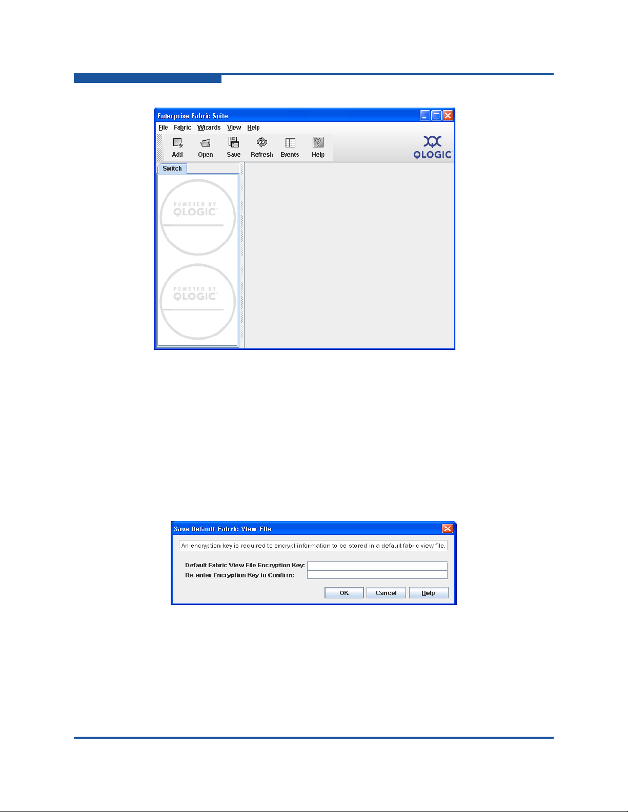
the Enterprise Fabric Suite window (Figure 1-4).
59266-01 B 1-5
Page 26
1–Using Enterprise Fabric Suite
Exiting Enterprise Fabric Suite
Figure 1-4. Enterprise Fabric Suite Window
Exiting Enterprise Fabric Suite
To exit a Enterprise Fabric Suite application session, on the File menu, click Exit.
If you have not yet saved the default fabric view file, the Save Default Fa bric V iew
File dialog box (Figure 1-5) prompts you to save the current fabric view as the
default fabric view file. Enter an encryption key in the Default Fabric File
Encryption Key box. Re-enter the encryption key in the Re-enter Encryption Key
to Confirm box. Click OK to save the current set of fabrics to the default fabric
view file in the working directory.
Figure 1-5. Save Default Fabric View File Dialog Box
1-6 59266-01 B
Page 27
1–Using Enterprise Fabric Suite
Uninstalling Enterprise Fabric Suite
The encryption key encrypts the sensitive data in the default fabric view file so that
no one can open the file without the encryption key. For information about
changing this encryption key, see “Changing the Encryption Key for the Default
Fabric View File” on page 1-8. If an encryption key has been defined and the View
File Auto Save and Load preference is enabled, the current fabric view is saved to
your default fabric view file when you close future Enterprise Fabric Suite
sessions. In addition to the default fabric view file, you can save and open other
fabric view files. See “Saving and Opening Fabric View Files” on page 1-8 for
more information.
To prevent Enterprise Fabric Suite from prompting you to save the default fabric
view file between Enterprise Fabric Suite sessions, enable (check) the View File
Auto Save and Load preference. For more information about preferences, see
“Setting Enterprise Fabric Suite Preferences” on page 1-9.
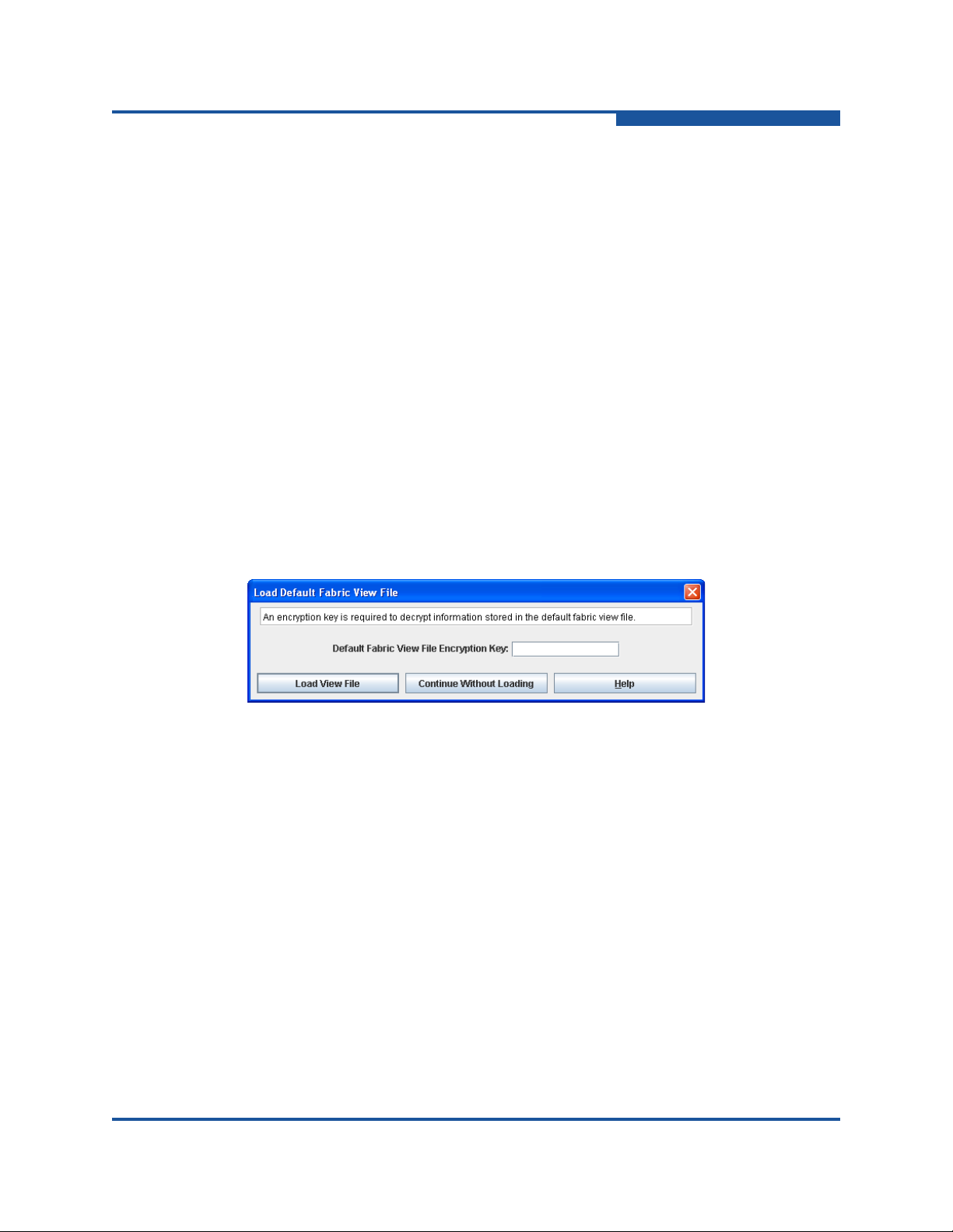
In your next Enterprise Fabric Suite session, the Load Default Fabric View File
dialog box (Figure 1-6) prompts you to load the default fabric view file and to
specify its encryption key, if one exists. In the Default Fabric File Encryption Key
box, enter the encryption key, and click Load View File. If you do not want to load
the default fabric view file, click Continue Without Loading to st art the Enterprise
Fabric Suite with no fabric displayed.
Figure 1-6. Load Default Fabric View File Dialog Box
Uninstalling Enterprise Fabric Suite
A program to uninstall Enterprise Fabric Suite was included as part of the
installation process. The UninstallerData folde r in the Inst all directory cont ains the
uninstall program Uninstall_Enterprise Fabric Suite. Also, a
shortcut/link to the uninstall program was installed in the installation directory
during the Enterprise Fabric Suite installation process.
The default installation directories are:
For Windows:
C:\Program Files\QLogic_Corporation\Enterprise_Fabric_S
uite
For Linux: /opt/QLogic_Corporation/Enterprise_Fabric_Suite
59266-01 B 1-7
Page 28

1–Using Enterprise Fabric Suite
Changing the Encryption Key for the Default Fabric View File
For Solaris:
/usr/opt/QLogic_Corporation/Enterprise_Fabric_Suite
For Mac OS X:
Users/qlogic/Applications/QLogic_Corporation/Enterprise
_Fabric_Suite
To uninstall the Enterprise Fabric Suite application, do the following:
For Windows, browse for the uninstall program file or the shortcut/link that
points to the uninstall program file. The uninstall program shortcut is in the
same folder as the program shortcut (Start menu, program group, on
desktop, or user specified) that is used to start the Enterprise Fabric Suite
application. Double-click the uninstall progra m file or shortcut/link, and follow
the instructions to uninstall the Enterprise Fabric Suite application.
For Linux, Solaris, or Mac OS X, execute the link to
Uninstall_Enterprise_Fabric_Suite. If no links were created during
the installation, enter the Uninstall_Enterprise_Fabric_Suite
command from the following directory:
UninstallerData/Uninstall_Enterprise_Fabric_Suite
Changing the Encryption Key for the Default
Fabric View File
To change the encryption key for the Enterprise Fabric Suite default fabric view
file, do the following:
1. On the File menu, click Save Default Fabric View File to view the Save
Default Fabric View File dialog box. Enter an encryption key in the Default
Fabric File Encryption Key box.
2. Re-enter the same encryption key in the Re-enter Encryption Key to Confirm
box.
3. Click OK to save the current set of fabrics to the default fabric view file in the
working directory.
Saving and Opening Fabric View Files
A fabric view file is one or more fabrics saved to a file. In addition to the Enterprise
Fabric Suite default fabric view file, you can save and open your own fabric view
files. To save a set of fabrics to a file, do the following:
1. On the File menu, click Save View As to view the Save View dialog box.
2. Enter a name for the fabric view file or click Browse to select an existing file.
Files are saved in the working directory.
1-8 59266-01 B
Page 29

1–Using Enterprise Fabric Suite
Setting Enterprise Fabric Suite Preferences
3. Enter a password. When you attempt to open this fabric view file, you will be
prompted for this password. If you leave the File Password box blank, no
password will be required when attempting to open this fabric view file.
4. Click OK to save the view.
To open a fabric view file, do the following:
1. On the File menu, click Open View File to view the Open View dialog box.
2. Enter a name for the fabric view file or click Browse to select an existing file.
3. If the fabric view file was saved with a password, enter the password and
click OK.
4. Click OK to open the view file.
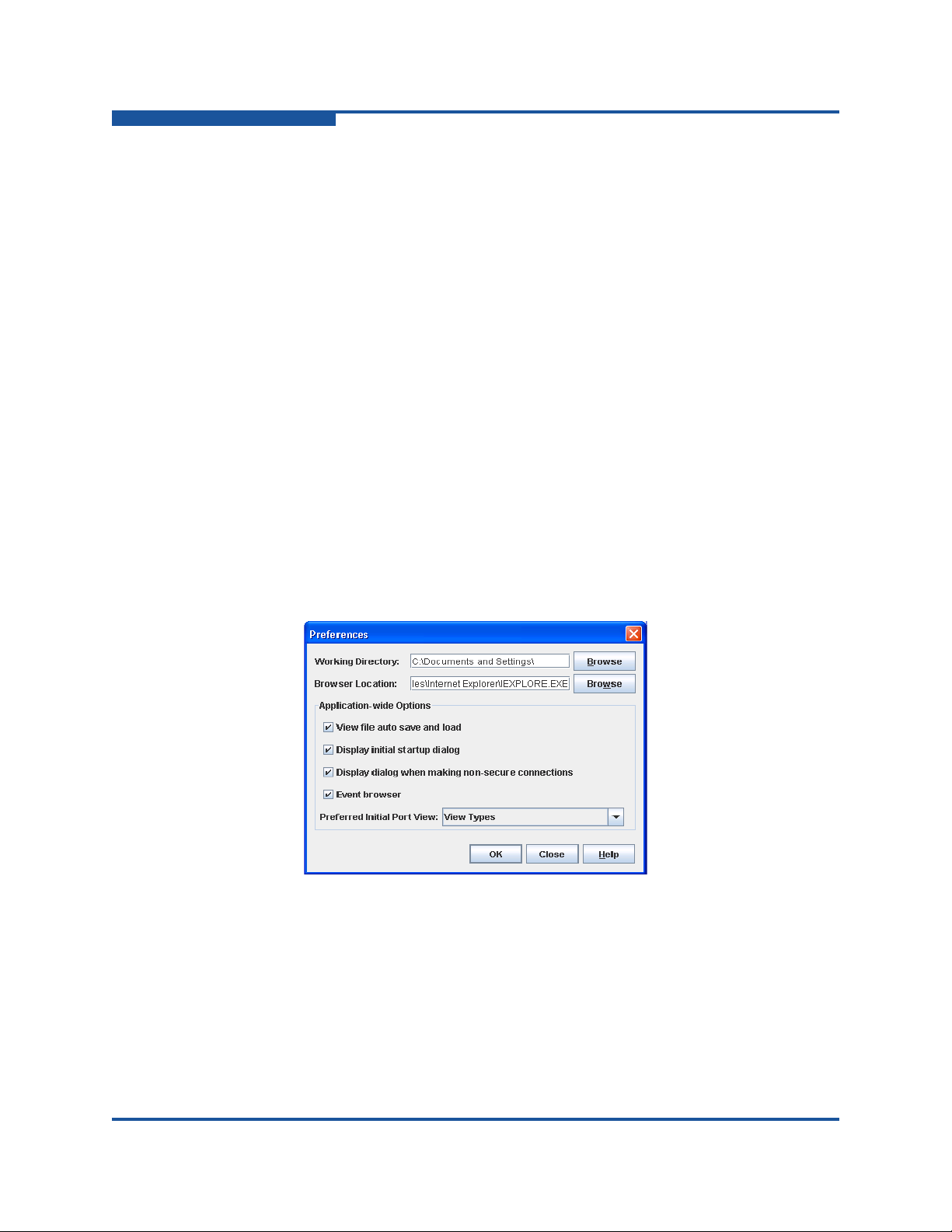
Setting Enterprise Fabric Suite Preferences
Using the Preferences dialog box (Figure 1-8) you can:
Change the location of the working directory in which to save files.
Change the location of the browser used to view the online help. The
Browser Location box is not supported/displayed for Macintosh OS X.
Enable (d efault) or disable the view file auto save and load feature. Refer to
“Exiting Enterprise Fabric Suite” on page 1-6 for more information on the
default fabric view file.
Enable (default) or disable the use of the Initial Start dialog box at the
beginning of a Enterprise Fabric Suite session. Refer to “Starting Enterprise
Fabric Suite” on page 1-3 for information about the Initial Start dialog box.
After a default fabric view file is created, this setting has no effect.
Enable (default) or disable the Non Secure Connections Check dialog box
that is displayed when you attempt to open a non secure fabric. If Display
Dialog When Making Non-secure Connections is enabled, you can open a
fabric with a non-secure fabric. Otherwise, you must have a secure
connection.
Enable (default) or disable the Event Browser. Refer to “Event Browser” on
page 2-21. If the Event Browser is enabled using the Preferences dialog box
(Figure 1-8), the next time Enterprise Fabric Suite is started, all events will
be displayed. If the Event Browser is disabled when Enterprise Fabric Suite
is started and later enabled, only those events from the time the Event
Browser was enabled and forward will be displayed.
59266-01 B 1-9
Page 30
1–Using Enterprise Fabric Suite
Setting Enterprise Fabric Suite Preferences
Choose the default port view when opening the faceplate display. You can
set the faceplate to reflect the current port type (default), port speed, port
operational state, or port transceiver media. Regardless of the default port
view you choose, you can change the port view on the faceplate display by
opening the View menu and selecting a different port view option. Refer to
the corresponding subsection for more information:
“Port Types” on page 6-14
“Port States” on page 6-15
“Port Speeds” on page 6-16
“Port Media Status” on page 6-18
Figure 1-7. Preferences Dialog Box – Enterprise Fabric Suite
To set preferences for your Enterprise Fabric Suite sessions, do the following:
1. On the File menu, click Preferences to view the Preferences dialog box.
2. Enter or browse for the paths to the working directory and browser.
3. In the Application-wide Options area, choose the preferences you want.
4. Click OK to save the changes.
Figure 1-8. Preferences Dialog Box—Enterprise Fabric Suite
Working Directory—path for the folder in which to save files. The default is
the installation directory.
Browser Location
—path for Internet browser program to use to view the
online help. The default is c:\Program Files (x86)\Internet
Explorer\iexplore.exe.
1-10 59266-01 B
Page 31

1–Using Enterprise Fabric Suite
Using Online Help
View file auto save and load—prevents (checked/default) or allows prompts
to save the default fabric view file between Enterprise Fabric Suite sessions.
Display initial startup dialog
of the Initial Start dialog box at the beginning of an Enterprise Fabric Suite
session. After a default fabric view file is created, this setting has no effect.
Display dialog
(checked/default) or prevents connections to a non-secure fabric. If this
preference is enabled, the application informs you when connecting to a
non-secure fabric, and enables you to connect. Otherwise, yo u must have a
secure connection.
Event browser
(checked/default) between Enterprise Fabric Suite sessions, or discards
those messages (unchecked). For information about events, see “Event
Browser” on page 2-21.
Preferred Initial Port View
represented by the ports of the faceplate display: port type (default), port
speed, port operational state, or port transceiver media. You can change the
port view on the faceplate display by opening the View menu and selectin g a
different port view option.
Using Online Help
The browser-based online help system can be accessed from the Enterprise
Fabric Suite application in several ways. Online help is also co ntext-sensitive; that
is, the online help opens to the topic that describes the current dialog box.
—enables (checked/default) or disables the use
—when making non-secure connections allows
—maintains event messages in the event browser
—determines the port information type
To view the first topic in the help system, choose one of the following:
On the Help menu, click Help Topics
Click Help on the tool bar
With no dialog box displayed, press F1
To view the help system to the topic that describes the dialog box you have open,
choose one of the following:
Click Help on the dialog box
Press F1
Viewing Software Version and Copyright
Information
To view Enterprise Fabric Suite software version and copyright information, on the
Help menu, click About.
59266-01 B 1-11
Page 32

1–Using Enterprise Fabric Suite
Menus
Data window tabs
Tool bar
Data
window
Graphic
window
Fabric
tree
Switch/fabric
name and
status
Enterprise Fabric Suite User Interface
Enterprise Fabric Suite User Interface
The Enterprise Fabric Suite application uses faceplate and backplate displays to
manage the switches in a fabric. The interface (Figure 1-9) consists of a menu
bar, fabric tree, graphic window, data windows (some with buttons), and data
window tabs. The topology display (Figure 1-9) appears on the graphic window
and shows all of the switches and connections in the fabric. The fabric names and
switch names appear on the fabric tree. Click a switch name or icon to display a
different switch faceplate on the graphic window. Information displayed on the
data windows corresponds to the selected data window tab.
Figure 1-9. Topology Display Elements
The faceplate and backplate displays are used to manage individual switches.
The faceplate displays show the front of a switch and its ports. The backplate
display shows the power supplies for single and dual power supply switches.
Figure 1-10 shows a faceplate display.
1-12 59266-01 B
Page 33

Enterprise Fabric Suite User Interface
Figure 1-10. Faceplate Display
1–Using Enterprise Fabric Suite
Figure 1-11 shows the backplate display for a dual power supply Fibre Channel
Switch.
Figure 1-11. Backplate Display
59266-01 B 1-13
Page 34

1–Using Enterprise Fabric Suite
Switch entries
Moveable
window border
Fabric name entry handle
Fabric name entry
Security lock icon
Enterprise Fabric Suite User Interface
NOTE:
Mouse-over information appears when you rest the cursor over key
elements in the Enterprise Fabric Suite interface, such as ports, LEDs, and
fabric tree entries.
Fabric Tree
The Enterprise Fabric Suite application enables you to manage the switches in
multiple fabrics. The fabric tree (Figure 1-9) provides access to the topology and
faceplate displays for any fabric or switch:
To view the topology display from the fabric tree, click a fabric entry.
To view the faceplate/backplate displays from the fabric tree, click a switch
entry.
A fabric name entry handle located to the left of an entry on the tree indicates tha t
the entry can be expanded or collapsed. Click this handle or double-click the entry
to expand or collapse a fabric tree entry. A fabric entry expands to show its
member switches. You can adjust the width of the fabric tree window by clicking
and dragging the moveable window border.
1-14 59266-01 B
Figure 1-12. Fabric tree
Page 35

1–Using Enterprise Fabric Suite
Enterprise Fabric Suite User Interface
Next to each fabric tree entry is a small icon that uses color to indicate operational
status:
A green icon indicates normal operation.
A yellow icon indicates that a switch is operationa l, but may require attention
to maintain maximum performance.
A red icon indicates a potential failure or non-operational state, as when the
switch is offline.
A blue icon indicates that a switch is unknown, unreachable, or
unmanageable.
If the status of a fabric is not normal, the fabric icon on the fabric tree indicates the
reason for the abnormal status. The same message is provided when you rest the
pointer on the fabric icon on the fabric tree.
The small lock icon next to the fabric icon on the fabric tree indicates a secure
fabric connection using Secure Socket Layer (SSL). The Security menu is
available only for the entry switch (out-of-band switch) on a secure fabric. On the
Switch menu, click Services to enable the SSL service for that switch. You must
then close the fabric and re-establish a secure connection to the fabric using SSL.
Graphic Window
The graphic window shows fabric, switch, and port information in the forms of the
fabric topology display, switch faceplate display (Figure 1-10), and switch
backplate display (Figure 1-11). To view the faceplate display, click a switch or
stack on the fabric tree, and on the View menu, click View Faceplate. To view the
backplate display, on the View menu, click View Backplate. You can adjust the
height of the graphic window by clicking and dragging the border that it shares
with the data window.
Data Windows and Tabs
The data window (Figure 1-9) displays a table of data and statistics associated
with the selected tab for the fabric, stack, or switch displayed on the graphic
window. The available data window tabs vary depending on the display. The
following data windows and tabs are available:
Devices—displays information about devices (hosts and storage targets)
connected to the switch. For more information, see “Devices Data Window”
on page 2-26.
Active Zoneset—displays the active zone set for the fabric including zones
and their member ports. For more information about this data window, see
“Viewing Active and Configured Zone Set Information” on page 4-4. For
information about zone sets and zones, see “Zoning Concepts” on page 4-1.
59266-01 B 1-15
Page 36

1–Using Enterprise Fabric Suite
Enterprise Fabric Suite User Interface
Switch—displays current network and switch configuration data for the
selected switch. For more information, see “Switch data window” on
page 5-7.
Link—displays a list of the inter-switch links in the fabric. For information on
switch links, see “Link Data Window” on page 2-7.
Stack Links—displays a list of the inter-switch links in the stack. For
information on switch links, see “Stack Links data window” on page 5-13.
Port Statistics—displays performance data for the selected ports. For more
information, see “Port Statistics Data Window” on page 6-8.
Port Information—displays information for the selected ports. For more
information, see “Port Information Data Window” on page 6-1.
Configured Zone sets—displays all zone sets, zones, and zone membership
in the zoning database. A zone is a named group of ports or devices. For
more information, see “Viewing Active and Configured Zone Set Informat ion”
on page 4-4.
Use the scroll bar to browse through the data. To adjust the length of the window,
click and drag the border that it shares with the graphic window. To adjust the
column width, move the pointer over the column heading border shared by two
columns until a right/left arrow graphic appears. Click and drag the arrow to the
preferred width.
Alerts Panel
The Alerts panel shows all reasons for status, including faults. The Alerts panel
entries are the highlighted rows between the faceplate image and the data
window entries.
The up/down arrows on the divider bar between the Alerts panel entries and data
windows enable you to move the divider bar up or down incrementally. With the
faceplate image on the graphic window and the data window displayed, you can
do the following:
Click the up arrow (on the left) to move the divider up to the top of the
Click the down arrow (on the right) to move the divider back to the middle.
Click and drag the divider bar to manually move it up or down.
window, completely hiding the faceplate image.
Click the down arrow again to completely hide the data window.
1-16 59266-01 B
Page 37

1–Using Enterprise Fabric Suite
Status
section
Enterprise Fabric Suite User Interface
Menus
The menus and the included tasks vary depending on the type of display. For
example, the Port menu and many of the Switch menu selections are only
available on the faceplate display. For information on the menus, see “Topology
Menu Options” on page 1-17 and “Faceplate Menu Options” on page 1-19.
Topology Display Menu
The Topology menu options, listed in Table 1-2, are available when a fabric is
selected on the fabric tree.
Menu Options
File Open View File
Figure 1-13. Alerts panel
Table 1-2. Topology Menu Options
Save View File
Save Default Fabric View File
Preferences
Exit
59266-01 B 1-17
Page 38

1–Using Enterprise Fabric Suite
Enterprise Fabric Suite User Interface
Table 1-2. Topology Menu Options (Continued)
Menu Options
Fabric Add Fabric
Remove Fabric
Nicknames
Fabric Tracker
Save Snapshot
Analyze Snapshots
Security Consistency Checklist
Rediscover Fabric
Start Performance View
FC TraceRoute
TR Mapping Manager
Show Event Browser
Switch
Options marked with an
asterisk (*) are available
only when one switch is
selected on the topology
display.
Stack
These options are avail-
able only when one stack is
selected on the topology
display.
View Refresh
Wizards Configuration Wizard
Delete*
Export Devices
Switch Properties*
Network Properties*
SNMP Properties*
Delete
Syslog
SNMP Properties
Set Date/Time
User Accounts
Security Consistency Checklist
Load Firmware
Edit Zoning Configuration
Layout Topology
Toggle Auto Layout
Remember Layout
1-18 59266-01 B
Page 39

Menu Options
Help Help Topics
Faceplate Display Menu
The Faceplate menu options, listed in Table 1-3, are available when a stack or
switch is selected on the fabric tree, except as noted.
Menu Options
File Open View File
1–Using Enterprise Fabric Suite
Enterprise Fabric Suite User Interface
Table 1-2. Topology Menu Options (Continued)
License Info
About
Table 1-3. Faceplate Menu Options
Save View File
Save Default Fabric View File
Preferences
Exit
Fabric Add Fabric
Remove Fabric
Nicknames
Fabric Tracker
FC TraceRoute
TR Mapping Manager
Show Event Browser
59266-01 B 1-19
Page 40

1–Using Enterprise Fabric Suite
Enterprise Fabric Suite User Interface
Table 1-3. Faceplate Menu Options (Continued)
Menu Options
Switch
These options are avail-
able only when a switch is
selected on the fabric tree.
Archive
Restore (entry switch only)
User Accounts
Set Date/Time
Switch Properties
Advanced Switch Properties (entry switch only)
Services
Call Home (Setup, Profile Manager , Message Queue, Test
Profile, Change Over)
Security Consistency Checklist
Network (Network Properties, IPsec Properties, IPsecIKE
Properties, IPsec Certs) (IP options require secure entry
switch)
SNMP (SNMP Properties, SNMP v3 Manager (secure
entry switch only))
Switch Diagnostics (Online Switch Diagnostics, Offline
Switch Diagnostics (entry switch only))
Toggle Beacons
Port Threshold Alarm Configuration
Load Firmware
Reset Switch (Hot Reset, Reset, Hard Reset)
Restore Factory Defaults
Features
Radius Servers (secure entry switch only)
Download Support File
FC Ping
1-20 59266-01 B
Page 41

1–Using Enterprise Fabric Suite
Enterprise Fabric Suite User Interface
Table 1-3. Faceplate Menu Options (Continued)
Menu Options
Stack
These options are avail-
able when a stack is
selected on the fabric tree.
Port
These options are avail-
able when a port is
selected on the faceplate
display.
Refresh Stack
Select All Ports
Syslog
SNMP Properties
Set Date/Time
User Accounts
Security Consistency Checklist
Reset (Hot Reset, Reset, Hard Reset)
Load Firmware
Move Switch Up (available when a switch other than the
top switch in a stack is selected on the faceplate display)
Move Switch Down (available when a switch other than
the bottom switch in a stack is selected on the faceplate
display)
Remove Switch (available when a switch in a stack is
selected)
Remove Links (available when an active port with an ISL
connected is selected)
Port Properties
Advanced Port Properties
Reset Port
Port Binding
Port Diagnostics
Online Port Diagnostics
Offline Port Diagnostics
Move Port (available only when there are unlice n sed
ports)
Zoning
Options marked with an
asterisk (*) are available
only when a switch is
selected on the fabric tree.
59266-01 B 1-21
Edit Zoning*
Resolve Zoning* (Capture Active Zoning, Restore Config-
ured Zoning, Capture Merged Zoning, View Merged/Configured Differences)
Edit Zoning Config*
Activate Zoneset*
Deactivate Zoneset*
Restore Default Zoning
Page 42

1–Using Enterprise Fabric Suite
Enterprise Fabric Suite User Interface
Table 1-3. Faceplate Menu Options (Continued)
Menu Options
Security
These options are avail-
able only on a secure entry
switch.
View Refresh
Wizards
Options marked with an
asterisk (*) are available
only when a switch is
selected on the fabric tree.
Help Help Topics
Edit Security
Edit Security Config
Activate Security Set
Deactivate Security Set
View Port Types
View Port States
View Port Speeds
View Port Media
View Faceplate
View Backplate
Configuration Wizard
Extended Credit Wizard*
Zoning Wizard*
License Info
About
Menu Shortcut Keys
Shortcut key combinations, available in both the topology and faceplate displays,
provide an alternative method of accessing menu options in the application. For
example, to exit the application, press ALT+F, and then press X. The shortcut key
combinations are not case-sensitive.
Press F1 to view the online help system. With no dialog box displayed, the online
help system opens to the first topic. With a dialog box displayed, the help system
opens to the topic describing that dialog box.
1-22 59266-01 B
Page 43

Shortcut Menus
Shortcut menus provide quick access to the menu options within the current
context of the application. They are displayed when you right-click on certain
areas of the topology or faceplate displays, such as inside the graphic window of
the topology display, or on a port on the faceplate display. The options available in
shortcut menus vary by display type (topology or faceplate) and where you click.
NOTE:
Opening the Topology Shortcut Menus
The topology display offers fabric, switch, and link shortcut menus:
To view the fabric shortcut menu, right-click the graphic window background.
1–Using Enterprise Fabric Suite
Enterprise Fabric Suite User Interface
Additionally, mouse-over information is displayed when you rest the cursor
over key elements in the Enterprise Fabric Suite interface, such as ports,
LEDs, and fabric tree entries.
The fabric shortcut menu presents selections to refresh the fabric, select all
switches, select all links, or layout topology.
To view the switch shortcut menu, right-click the switch icon on the graphic
window . The switch shortcut menu present s selections to refresh the switch ,
delete the switch from the display, open the Switch Properties dialog box, or
open the Network Properties dialog box.
To view the link shortcut menu, right-click the link. The Link shortcut menu
presents a selection to delete the link from the display.
Opening the Faceplate Shortcut Menus
To view the faceplate shortcut menu, right-click the faceplate image. The faceplate
shortcut menu presents selections to refresh the switch, select all ports, open the
Switch Properties dialog box, open the Network Properties dialog box, open the
SNMP Properties dialog box, use the Extended Credits Wizard, open the Port
Properties dialog box, run port diagnostic tests, configure RADIUS servers, open
the Services dialog box, and view the Security Consistency Checklist dialog box.
If no ports are selected, the port-related tasks will be unavailable on the shortcut
menu. Right-click a port to view the corresponding shortcut menu. Press SHIFT or
CTRL to select more than one port. If multiple ports are selected, right-click one of
the selected ports.
NOTE:
The shortcut key combinations are not case-sensitive
59266-01 B 1-23
Page 44

1–Using Enterprise Fabric Suite
Enterprise Fabric Suite User Interface
Tool Bar
The tool bar consists of a row of graphical buttons that provide access to
Enterprise Fabric Suite functions. The tool bar buttons are an alternative method
to using the menus.
The Tool bar options are described in Table 1-4.
Button Description
Add Fabric—adds a new fabric to the fabric view
Open View File—opens an existing fabric view file
Save View As—saves the current fabric view to a file
Table 1-4. Tool Bar Options
Refresh—updates the topology or faceplate display with current information
Event Browser—opens the events browser
Edit Zoning—opens the Edit Zoning dialog box (available only when a
switch or stack is selected on the fabric tree)
Edit Security—opens the Edit Security dialog box (available only on a
secure entry switch)
Help Topics—opens the online help file
Working with Switches and Links
Switch and link icons are selectable and moveable, and serve as access points for
other displays and menus. You select switches and links to display information
about them, modify their configuration, or delete them from the display.
Context-sensitive popup menus are displayed when you right-click on a switch or
link icon, or on the background of the topology display and graphic window.
1-24 59266-01 B
Page 45

1–Using Enterprise Fabric Suite
Enterprise Fabric Suite User Interface
Switch icon shape and color provide information about the switch and its
operational state. Lines represent links between switches. The topology display
uses green to indicate normal operation, yellow to indicate operational with errors,
red to indicate a potential failure or non-operational state, and blue to indicate
unknown, unreachable, or unmanageable. For more information about topology
display icons, see “Displaying Fabric Status” on page 2-8.
Selected ISL links on the topology display are displayed with a heavier line.
Selected switches are displayed with a light blue background. You can select
switches and links the following ways:
To select one switch or link, click the switch or link.
To select a group of switches or links, press SHIFT or CTRL while clicking
each switch or link.
To select all switches or links, right-click anywhere on the graphic window
background, and click Select All Links or Select All Switches on the
shortcut menu.
To cancel all selections, click on the background of the graphic window.
To un-select one switch or link in a group of selected switches or links, press
SHIFT or CTRL while clicking the switch or link.
To add a switch or link to a group of selected switches or links, press SHIFT
or CTRL while clicking the switch or link.
You can arrange individual switch icons on the topology display or allow
Enterprise Fabric Suite to arrange all switch icons for you:
To move an individual switch icon, click and drag the icon to another location
on the graphic window. Links stretch or contract to remain connected.
To arrange all switch icons on the topology display automatically, on the
View menu, click Layout Topology.
By default, the Toggle Auto Layout box on the View menu is selected, which
causes Enterprise Fabric Suite to arrange the icons when you click Layout
Topology.
You can save a custom arrangement, or layout, and restore that layout during an
Enterprise Fabric Suite session. To arranging the icons, on the View menu, click
Remember Layout. To restore the saved layout, on the View menu, unselect the
Toggle Auto Layout option, and click Layout Topology.
59266-01 B 1-25
Page 46

1–Using Enterprise Fabric Suite
Enterprise Fabric Suite User Interface
Working with Ports
Ports are selectable and serve as access points for other displays and menus.
You select ports to display information about them on the data window or to
modify them. Context-sensitive popup menus appear when you right-click the
faceplate image or on a port icon. See “Managing Ports” on page 6-1 for detailed
port information.
Selected ports on the faceplate display are outlined in white. You can select ports
in the following ways:
To select a port, click the port.
To select all ports, right-click on the faceplate image, and click Select All
Ports on the shortcut menu.
To select a range of consecutive ports, click a port, press and hold SHIFT,
and then click the last port in the range. The Enterprise Fabric Suite
application selects both end ports and all ports in between the end ports.
NOTE:
When using the SHIFT key to select a range of ports, the first port you click
in the range is the anchor selection. Subsequent ranges are based on this
anchor selection. For example, when you click port 4 and port 9 r espectively,
port 4 becomes the anchor selection. The next range includes all ports
between port 4 and the next port you select.
To select several non-consecutive ports, press and hold CTRL while clicking
each port.
To deselect ports, press and hold CTRL while clicking each port.
To cancel a selection, press and hold CTRL, and click it again.
1-26 59266-01 B
Page 47

2 Managing Fabrics
This chapter describes the options for managing fabrics.
Fabric Firmware and Software Versions
The Fabric Tracker option enables you to generate a snapshot or baseline of
current system version information, which can be viewed, analyzed and compared
to other snapshot files, and exported to a file. Information includes date and time,
switch active firmware version, device hardware, drivers, and firmware version
from FDMI.
The Snapshot Analyzer option enables you to do the following:
Compare two snapshots.
Detect mismatches of firmware and driver versions.
Detect devices that have been moved, added to, or re moved from the fabric.
Saving a Version Snapshot
To save the current snapshot to an XML file:
1. In the faceplate display, on the Fabric menu, click Fabric Tracker, and then
click Save Snapshot.
2. Enter a filename.
3. Click Save to save the snapshot as an XML file.
Viewing and Comparing Version Snapshots
To view and analyze system version information:
1. On the Fabric menu, click Fabric Tracker, and then click Analyze
Snapshots to view the Fabric Version Snapshot Analysis dialog box
(Figure 2-1).
2. Click Browse to open and view the snapshot files in the corresponding tab
pages (Summary, Differences, Reports).
3. Click Close to exit the Fabric Version Snapshot Analysis dialog box.
59266-01 B 2-1
Page 48

2–Managing Fabrics
Fabric Firmware and Software Versions
Figure 2-1. Fabric Version Snapshot Analysis Dialog Box
The color key below the scrollable area defines the meanings of the colors used.
The Summary tab page shows a brief description of the changes that have
occurred between the older snapshot and the newer one. Use the Summary tab
page to quickly view what has changed. The Differences tab page shows a
side-by-side comparison of two snapshots.
The timestamp of each snapshot appears above the scroll area showing that
snapshot. The background color of the older snapshot is darker than the
background of the newer snapshot. The arrow icon between the snapshot
selectors always points from the older snapshot to the newer one. If the two
snapshots have the same timestamp, the arrow is not displayed. The scroll bars
are synchronized to view the same portion of each snapshot file simultaneously.
To resize each pane:
1. Click and drag the separator bar between the two panes.
2. At the top of the separator bar between the two panes, click the left/right
arrows to close the corresponding pane. The left/right arrows move to one
side.
Exporting Version Snapshots to a File
The Reports tab page enables you to select one report to sa ve to a text file. There
are two types of reports: Summary report and Detailed report.
Summary report shows the same format displayed on the Summary tab
page without the color highlighting.
Detail report shows a detailed breakdown of the differences.
Click Export to save the selected report to a text file.
2-2 59266-01 B
Page 49

Managing the Fabric Database
A fabric database contains the set of fabrics that you add during a Enterprise
Fabric Suite session. Initially, if you do not open an existing fabric or fabric view
file, the Enterprise Fabric Suite application opens with an empty fabric database.
Adding a Fabric
To add a fabric to the database:
1. On the Open menu, click Add Fabric to view the Add a New Fabric dialog
box (Figure 2-2).
2–Managing Fabrics
Managing the Fabric Database
Figure 2-2. Add a New Fabric Dialog Box
2. Enter a unique fabric name in the Fabric Name box. This step is optional.
NOTE:
Assigning a fabric name is recommended.
3. In the Entry Switch box, enter the IP address or Domain Name Server (DNS)
name of the switch through which to manage the fabric. For more
information, see “Network IP Configuration” on page 5-30.
4. Enter an account name and password. The factory login name and
password are admin and password. The password is for the switch, and is
stored in the switch firmware. For information on user accounts, see
“Managing User Accounts” on page 5-1.
5. Click Add Fabric.
59266-01 B 2-3
Page 50

2–Managing Fabrics
Managing the Fabric Database
6. For security reasons, you are prompted to change your user account
password initially set up by the administrator. You are prompted each time
you attempt to view the fabric until you change the password. Click OK, and
change the user account password.
NOTE:
If the entry switch has SSL (Secure Socket Layer) enabled, the switch
generates and displays a Verify Certificate dialog box that you must
accept before gaining access to the fabric.
Removing a Fabric
To delete a fabric from the database:
1. Select a fabric in the fabric tree.
2. On the Fabric menu, click Remove Fabric.
3. The application automatically removes the fabric whether you click OK or
not.
Opening a Fabric View File
A fabric view file is one or more fabrics saved to a file. To open an existing view
file:
1. On the File menu, click Open View File, or click Open to view the Open
View dialog box. If the fabric you are currently viewin g has changed, you are
prompted to save the changes to the fabric view file with the Save View
dialog box before opening a different view file.
2. Enter the name of the file to open, and enter a file password if a password
was entered when this fabric view file was saved.
3. Click OK.
NOTE:
To maximize system performance and reduce the fabric event logs,
limit the number of large fabrics open at one time.
Saving a Fabric View File
To save a fabric view file:
1. On the File menu, click Save View As to view the Save View dialog box.
2. Enter a new file name and a file password, if necessary.
3. Click OK.
2-4 59266-01 B
Page 51

Rediscovering a Fabric
After making changes to or deleting switches from a fabric view, it may be helpful
to view the actual fabric configuration again. The Rediscover Fabric option clears
the current fabric information being displayed, and rediscovers all switch
information.
To rediscover a fabric, on the topology display on the Fabric menu, click
Rediscover Fabric. The Rediscover function is more comprehensive than the
Refresh function.
Deleting Switches and Links
The Enterprise Fabric Suite application does not automatically delete switches or
links that have failed or have been physically removed from the fabric Fibre
Channel network. In these cases, you can delete switches and links to bring the
display up to date. If you delete a switch or a link that is still active, the Enterprise
Fabric Suite application restores it automatically. You can also refresh the display.
To delete a switch from the topology display:
2–Managing Fabrics
Adding a New Switch to a Fabric
1. Select a switch in the topology display.
2. On the Switch menu, click Delete.
To delete a link:
1. Select a link in the topology display.
2. Right-click the link, and then click Delete on the shortcut menu.
Adding a New Switch to a Fabric
If there are no special conditions to be configured for a new switch, plug in the
switch; the switch becomes functional with the default fabric configuration. The
default fabric configuration settings are:
Fabric zoning is sent to the switch from the fabric.
All 8Gb/s ports are GL_Ports.
The default IP address 10.0. 0.1 is assigned to the switch without configuring
a gateway or boot protocol (RARP, BOOTP, and DHCP).
If you are adding a new switch to a fabric and do not want to accept the default
fabric configuration:
1. If the switch is not new from the factory, reset the switch to the factory
configuration before adding the switch to the fabric by selecting Restore
Factory Defaults from the Switch menu.
2. If you want to manage the switch through the Ethernet port, configure the IP
address using the Network Properties dialog box or the Configuration
Wizard.
59266-01 B 2-5
Page 52

2–Managing Fabrics
Replacing a Failed Switch
3. Configure any special switch settings. T o view the Zon ing Config dialog box,
on the Zoning menu, click Edit Zoning Config.
4. Plug in the ISLs, but do not connect the devices.
5. Configure the port types for the new switch using the Port Properties dialog
box.
6. Connect the devices to the switch.
7. To make any necessary zoning changes, on the Zoning menu, click Edit
Zoning to view the Edit Zoning dialog box.
Replacing a Failed Switch
Use the following procedure to replace a failed switch for which an archive is
available.
1. Turn off the power to the failed switch and disconnect the AC cords. Note
port locations and remove the interconnection cables and small form-factor
pluggable (SFPs).
2. Remove the failed switch.
3. Mount the replacement switch in the location where the failed switch was
removed.
4. Install the SFPs using the same ports that were used on the failed switch.
Do not reconnect inter-switch links, target devices, and initiator devices at
this time. Doing so could invalidate the fabric zoning configuration.
5. Attach the AC cords and power up the switch.
6. Connect the Ethernet port to the LAN used for Enterprise Fabric Suite and
configure the IP address using the Network Properties dialog box or the
Configuration Wizard.
7. Restore the configuration on the replacement switch:
a. Open a new fabric through the replacement switch.
b. On the faceplate display for the replacement switch on the Switch
menu, click Restore.
c. In the Restore dialog box, enter the archive file from the failed switch
or browse for the file.
d. Click Restore.
8. On the Switch menu, click Reset Switch to reset the replacement switch to
activate the configuration. This configuration comes from the failed switch,
including the domain ID and the zoning database.
2-6 59266-01 B
Page 53

9. Reconnect the inter-switch links, target devices, and initiator devices to the
replacement switch using the same ports as were used on the failed switch.
Displaying Fabric Information
The topology display is your primary tool for monitoring a fabric. The graphic
window of the topology display provides status information for switches,
inter-switch links, and the Ethernet connection to the management workstation.
For more information, see the Link data window (Figure 2-3).
The topology display data windows show device, active zone set, switch, and link
information.
For information on devices in a fabric, see “Devices Data Window” on
page 2-26.
For information on zone definitions for the active zone set, see “Viewing
Active and Configured Zone Set Information” on page 4-4.
For information about the Name Server and Switch data windows, see
“Switch data window” on page 5-7.
2–Managing Fabrics
Displaying Fabric Information
For information on switch links, see “Link Data Window” on page 2-7.
Link Data Window
The Link data window (Figure 2-3) displays information about all switch links in
the fabric or selected links in the topology display. This information includes the
switch name, the port number at the end of each link, and the link status icon. To
view the Link data window , select a fabric in the fabric tree, and then click the Link
tab.
59266-01 B 2-7
Page 54

2–Managing Fabrics
Displaying Fabric Information
Figure 2-3. Link Data Window
Displaying Fabric Status
The fabric updates the topology and faceplate displays by forwarding changes in
status to the management workstation as they occur. You can allow the fabric to
update the display status, or you can refresh the display at any time. To refresh
the topology display, do one of the following:
Click Refresh
On the View menu, click Refresh
Press F5
Right-click anywhere in the background of the topology display, and click
Refresh Fabric on the shortcut menu.
The topology display uses switch and status icons to provide status information
about switches, inter-switch links, and the Ethernet connection. The switch status
icons, displayed on the left side of a switch, vary in shape and color. Switches
controlled by an Ethernet Internet Protocol have a colored Ethernet icon displayed
on the right side of the switch. Table 2-1 shows the different switch icons and their
meanings.
2-8 59266-01 B
Page 55

2–Managing Fabrics
Transparent Router
NOTE:
Enterprise Fabric Suite may not support all firmware versions. If the version
of Enterprise Fabric Suite is not supported, a warning status message
appears: FW/GUI mismatch. A switch with this status is still manageable, but
some functions may not be available. For firmware compatibility information,
see the Enterprise Fabric Suite Release Notes.
Table 2-1. Topology Display Switch and Status Icons
Switch Icon Description
Switch status icons
Normal operation (green)
Warning–operational with errors (yellow)
Critical–potential failure (red)
Unknown–communication status unknown, unreachable,
or unmanageable (blue)
Transparent Router
The Transparent Router feature provides inter-fabric routing to enable controlled
and limited access between devices on a QLogic fabric and devices on a fabric o f
Brocade or Cisco switches.
Generally, to configure Transparent Router on a QLogic switch:
1. Change the port type of a selected port to TR_Port.
2. Map local (QLogic) and remote (e.g., Brocade/Cisco) fabric devices across
the TR_port.
3. Copy/paste the zoning commands automatically generated (by TR Mapping
Manager) into the remote fabric management application.
Fabric management switch Ethernet icons
Ethernet connection normal (green)
Ethernet connection warning (yellow)
Ethernet connection critical (red)
Switch is not manageable with this version of Enterprise
Fabric Suite. Use the management application that was
shipped with this switch.
59266-01 B 2-9
Page 56

2–Managing Fabrics
Transparent Router
The local QLogic fabric may consist of one or multiple switches connected by their
ISLs. A specific device attached to a local switch can be mapped with one or more
devices in one remote fabric over only one TR_Port on that switch. If a device
attached to a QLogic switch is mapped with multiple devices in the same remote
fabric, the same TR_Port must be used.
A device attached to a remote fabric can be mapped with multiple devices in
multiple local fabrics. If a device in a remote fabric is mapped with multiple
devices in the local fabric attached to a given switch, the same TR_Port on that
switch must be used for all mappings involving that remote device. However, the
same remote device can be mapped with other local devices attached to a
different switch in the same local fabric over a TR port from that switch. A remote
device can be mapped through more than one TR port, as long as each of those
TR ports is on a switch.
Furthermore, you cannot map a local device to a remote device over an E_Port to
another local switch and then over a TR_Port to the remote switch. The
transparent route cannot include an E_Port on the local fabric.
Local devices will not discover remote devices until the corresponding inter-fabric
zones are activated on both the local and remote fabrics. To remove a mapping, in
addition to removing the local inter-fabric zone, you must also remove the
corresponding remote inter-fabric zone.
NOTE:
When a local device is mapped over a TR_Port to a remote device, the local
device and its TR_Port appear as an NPIV connected device in the remote
fabric. It is possible, though not recommended, to map such a local device
over a second TR_Port to a local device in a second local fabric. In this
case, if you merge the two local fabrics, the transparent route becomes
inactive for the devices that now have a path over an ISL, and an alarm is
generated.
For details of switches supported in a remote fabric, see the Release Notes for the
switch. A user (admin rights is required) can configure TR mappings to connect
devices on the local fabric with devices on remote fabrics.
The transparent route between these devices is accomplished by connecting a
remote switch to a TR_port on the switch, mapping the devices together, and then
creating and activating the IFZ (inter-fabric zones) in both fabrics. Each fabric will
contain a matching IFZ. Each IFZ must contain exactly three WWN members: the
local device, the remote device, and the TR_Port attached to the remote fabric.
2-10 59266-01 B
Page 57

2–Managing Fabrics
Transparent Router
NOTE:
Be sure to configure the TR_Port before connecting the remote fabric to the
switch. If the remote fabric is connected to a port on the switch that is not a
TR_Port, the two fabrics may establish an E_Port connection and the local
and remote fabrics may merge. This mixed fabric is not a supported
configuration. If the port type is changed to TR_Port after connecting the
remote fabric, a port reset may be required to completely establish the TR
connection.
A TR_Port is used as a bridge between the transparent router’s local fabric and a
remote fabric. A TR_Port uses standard NPIV login methods to attach to the
remote fabric. For remote Brocade or Cisco fabrics, the switch to which the
TR_Port connects must support N-Port ID Virtualization (NPIV) and for Brocade
fabrics the interoperability mode must be configured to InteropMode=0. The
TR_Port logs into the remote fabric using the WWN of the TR_Port. The TR_Port
accesses fabric services of the remote fabric, such as Name Server and
Management Server, and may receive registered state change notifications
(RSCNs). The TR_Port uses FDISCs to login proxies for devices attached to an
N_Port on the switch. Any of the switch 8Gb ports may be configured as a
TR_Port.
NOTE:
Since Cisco switches do not support the Unzoned Name Server, Cisco
fabrics must be “pre-zoned” before you can set up TR mappings to a remote
Cisco fabric using the TR Mapping Manager dialog box. The Cisco fabric
zone set must be changed to add zones so that the WWNs of the remote
devices to be mapped and the WWNs of the switch TR ports are zoned
together. For more information, see the Cisco documentation for specific
information to configure zoning. Retain these zones in the zone set after
completion of the TR mapping as a best practice, until you no longer need to
map the device to the local fabric.
TR Mapping Manager Dialog Box
The TR Mapping Manager dialog box (Figure 2-4) displays the currently mapped
inter-fabric routes. You can create new inter-fabric routes, view detail information
on existing inter-fabric routes, and remove existing inter-fabric routes. To view the
TR Mapping Manager dialog box, on the Fabric menu, click TR Mapping
Manager.
59266-01 B 2-11
Page 58

2–Managing Fabrics
Transparent Router
NOTE:
To create a new TR mapping, click Add, or on the Edit menu, click Add to view
the Add TR Mapping dialog box. See ”Add TR Mapping Dialog Box” on page 2-13
for more information.
Select a TR mapping member in the TR Mapping List window to:
Delete that TR mapping member
View detailed information for that TR mapping member in the Selected TR
The Merge Auto Save option in the Config Zoning dialog box must be
selected before you can view the TR Mapping Manager dialog box. See
“Merge Auto Save” on page 4-10 for more information.
Mapping area
Figure 2-4. TR Mapping Manager Dialog Box
2-12 59266-01 B
Page 59

After you click OK in the TR Mapping Manager dialog box, the IFZs are created
and saved to the switch. If there is an active zone set with TR mappings, the old
IFZs are deleted and replaced with the new IFZs, and then the active zone set is
re-activated. If there is no active zone set, a zone set named TR_MAPPING_SET”
(default name) is created, the new IFZs are added to the zone set, and then the
zone set is activated. If there are no TR mappings, the old IFZs are deleted from
the active zone set, and then the active zone set is re-activated. If there are no
zones and no IFZs in the active set, the active zone set is deactivated.
Removing an Inter-Fabric Route
To remove an inter-fabric route:
1. On the faceplate display on the Fabric menu, click TR Mapping Manager.
2. In the TR Mapping Manager dialog box (Figure 2-4), select a TR mapping
member from the TR Mapping list, and then click Remove, or on the Edit
menu, click Remove.
A warning dialog box prompts you to confirm the removal of the selected
mapping members.
2–Managing Fabrics
Transparent Router
3. Click OK to confirm the removal of the selected TR mapping member.
Add TR Mapping Dialog Box
The Add TR Mapping dialog box (Figure 2-5) enables you to map a new
inter-fabric zone. The Add TR Mapping dialog box displays the selectable local
devices, remote devices, and TR-configured ports that can be mapped to the
inter-fabric zone. The Add TR Mapping dialog box appears after you click Add, or
on the Edit menu, click Add in the TR Mapping Manager dialog box.
NOTE:
You can map a remote device through multiple TR ports, as long as each of
those TR ports are on different switches.
Select a local device from the 1 Select a Local Device column to display the
selectable remote devices in the 2 Select a Remote Device column. After
selecting a remote device, the selectable TR ports appear in the 3 Select a TR
Port column.
59266-01 B 2-13
Page 60

2–Managing Fabrics
Transparent Router
Figure 2-5. Add TR Mapping Dialog Box
Mapping a New Inter-Fabric Zone
NOTE:
The local fabric port to be used in the inter-fabric zone must be configured
as a TR_Port before the devices are mapped. See “Port Types” on
page 6-14 for information on changing port types.
To map a new inter-fabric zone:
1. On the faceplate display on the Fabric menu, click TR Mapping Manager.
2. On the TR Mapping Manager dialog box (Figure 2-4), click Add, or on the
Edit menu, click Add.
3. On the Add TR Mapping dialog box (Figure 2-5), select a local device from
the 1 Select a Local Device column.
4. Select a remote device option from the 2 Select a Remote Device column.
5. Select a TR port option from the 3 Select a TR Port column.
2-14 59266-01 B
Page 61

2–Managing Fabrics
Transparent Router
6. After selecting an option from the 3 Select a TR Port column, the OK button
becomes active.
7. Click OK to save the changes and close the Add TR Mapping dialog box.
8. Verify that the new TR mapping members appear in the TR Mapping list of
the TR Mapping Manager dialog box, and then click OK.
NOTE:
After you click OK in the TR Mapping Manager dialog box, the IFZs are
created and saved to the switch. If there is an active zone set with TR
mappings, the old IFZs are deleted and replaced with the new IFZs, and
then the active zone set is re-activated. If there is no active zone set, a zone
set named TR_MAPPING_SET” (default name) is created, the new IFZs are
added to the zone set, and then the zone set is activated. If there are no TR
mappings, the old IFZs are deleted from the active zone set, and then the
active zone set is re-activated. If there are no zones and no IFZs in the
active set, the active zone set is deactivated.
59266-01 B 2-15
Page 62

2–Managing Fabrics
Transparent Router
Remote Fabric Zoning Dialog Box
The Remote Fabric Zoning dialog box (Figure 2-6) enables you to generate and
save a text file containing the zoning commands required to be executed on the
remote fabric so that the inter-fabric connection using a TR port is established.
The user can choose the kind of remote fabric/switches to connect with the TR
port so that Enterprise Fabric Suite knows which zoning commands to generate
for the user. Fabrics with Brocade and Cisco switches are supported.
NOTE:
Before modifying zoning, it is recommended that you back up the
configuration.
Figure 2-6. Remote Fabric Zoning Dialog Box
To create a zoning commands text file for the remote fabric:
1. On the faceplate display on the Fabric menu, click TR Mapping Manager.
2. Create a new TR mapping for a inter-fabric zone, if one does not exist. See
”Mapping a New Inter-Fabric Zone” on page 2-14 for more information.
3. In the TR Mapping Manager dialog box (Figure 2-4), select an entry from the
TR Mapping List window.
4. On the File menu, click Generate Remote Zoning.
2-16 59266-01 B
Page 63

2–Managing Fabrics
Transparent Router
5. In the Remote Fabric Zoning dialog box (Figure 2-6), if you made and saved
changes in the TR Mapping Manager dialog box, you can choose the type of
zoning commands to view in the Suggested Remote Fabric Zoning
Commands window of the Remote Fabric Zoning dialog box.
Choose one of the following options from Select Set of Zoning Commands to
View:
The Comprehensive Zoning Commands for Initial TR Setup option to
show the list of zoning commands to set up all the IFZs.
The Zoning Commands Only for Changes to TR Mappings option to
show the list of zoning commands only for changes you just made
during this session (after opening the TR Mapping Manager dialog
box).
NOTE:
The Remote Fabric Zoning dialog box displays the Select Set of Zoning
Commands to View option only if you made and saved changes in the TR
Mapping Manager dialog box. If you opened the Remote Fabric Zoning
dialog box after opening the File menu, and clicking Generate Remote
Zoning, the Select Set of Zoning Commands to View option is not
displayed, and the Suggested Remote Fabric Zoning Commands window
displays the list of zoning commands to set up all the IFZs.
6. Choose one of the following options from the Remote Switch Type
drop-down list to generate the corresponding zoning commands:
Brocade—to connect remotely with Brocade switches
Cisco—to connect remotely with Cisco switches
7. Enter the Configuration Name, which is used as the zone set name in the
commands. This must be the same zone set name as the zone set on the
remote fabric to which this zoning will be applied, or else the commands
generated can be saved and edited to change the zone set name as
needed. The default Configuration Name displayed is TRoutesCfg.
8. Select one of the following:
Clear the New Configuration option if the remote fabric has an active
zone set. Executing the updated zoning commands on the remote
fabric automatically adds the changes to the already active zone set,
provided that the Configuration Name entered is the same as the
name of that active zone set.
59266-01 B 2-17
Page 64

2–Managing Fabrics
Transparent Router
9. Click Export and select a path name (TXT file extension only) in the Save
NOTE:
If the commands are run and the Configuration Name is not the
name of the active zone set in the remote fabric, the commands
attempt to replace the active zone set with a new zone set with
the new name, containing only the Inter Fabric Zones. This will
not succeed unless you respond to CLI queries to accept
activation of this new zone set.
Select the New Configuration option if the remote fabric does not
have an active zone set. Executing the commands on the remote
fabric automatically adds the commands (inter-fabric zones) to create
and activate the zone set. The Configuration Name entered is the
name of the active zone set that is created.
dialog box.
Selecting the same path name will overwrite the first path name.
10. Click Save to save the zoning commands text file on your workstation.
NOTE:
The commands generated for Cisco switches assume that zoning will
be applied to VSAN 1. If this is not the correct VSAN, you must edit the
commands accordingly before executing the commands.
2-18 59266-01 B
Page 65

Transparent Routes Data Window
The Transparent Routes data window displays the currently conf igured inter-fabric
zones/routes using a TR_Port.
2–Managing Fabrics
Transparent Routes Data Window
Figure 2-7. Transparent Routes Data Window
Table 2-2 describes the entries in the Transparent Routes data window.
Table 2-2. Transparent Routes Data Window Entries
Entry Description
Route Route number reference for each listing in the Transparent
Routes data window table
State The current TR mapping state (Active or Inactive)
Active—Indicates that the mapping's TR port is on this
switch, and both devices have logged in.
Inactive—Indicates that the mapping's TR port is on this
switch, and the mapping is not active. The reasons are
shown in the details display as the three Status column
entries (one for the overall mapping and one for each
device in the mapping).
Device A The WWN of one of the two devices linked by the TR mapping.
Assigned nicknames are also displayed.
59266-01 B 2-19
Page 66

2–Managing Fabrics
Transparent Routes Data Window
Table 2-2. Transparent Routes Data Window Entries
Entry Description
Device B The WWN of the other device linked by the TR mapping.
Details Click (i) in the Details column to view the Transparent Route
The Transparent Route dialog box (Figure 2-8) displays detailed information about
the transparent route you selected from the T ransparen t Routes data window. The
state of the route (Active or Inactive) is shown, and Port WWN, TR Port WWN,
and Status fields are displayed for both sides of the route. Device A will not
necessarily correspond to the switch side of the route, as the end points of the
route could be in any order.
Assigned nicknames are also displayed.
dialog box, which displays detailed information on the transparent route.
Figure 2-8. Transparent Route Dialog Box
2-20 59266-01 B
Page 67

Event Browser
Column sorting
buttons
Severity
column
The Event Browser displays a list of events gen erated by the switches in the fabric
and the Enterprise Fabric Suite application. Events that are generated by the
Enterprise Fabric Suite application are not saved on the switch, but can be saved
to a file (.xml, .csv, .txt) during an Enterprise Fabric Suite session.
The Event Browser (Figure 2-9) lists events that have occurred, displaying the
severity, time, source, type, and description of the events. The maximum number
of entries allowed in the Event Browser is 10,000. The maximum number of
entries allowed on a switch is 1,200. Once the maximum is reached, the oldest
events in the event list are deleted when new events occur. Event entries from the
switch use the switch time stamp, while event entries generated by Enterprise
Fabric Suite have a workstation time stamp. You can filter, sort, and export the
contents of the Event Browser to a file. The Event Browser begins recording when
it is enabled and Enterprise Fabric Suite is running.
If the Event Browser is enabled using the Preferences dialog box, the next time
Enterprise Fabric Suite is started all events from the switch log appear. If the
Event Browser is disabled when Enterprise Fabric Suite is started and later
enabled, only those events that occur after the time the Event Browser was
enabled will appear.
2–Managing Fabrics
Transparent Routes Data Window
To display the Event Browser, on the Fabric menu, click Show Event Browser . If
the Show Event Browser selection is grayed-out, you must first enable the Events
Browser preference. See “Setting Enterprise Fabric Suite Preferences” on
page 1-9.
Figure 2-9. Event Browser Dialog Box
59266-01 B 2-21
Page 68

2–Managing Fabrics
Transparent Routes Data Window
The icons in the Severity column identify the operational state of the port, as
described in Table 2-3.
State Description
Alarm—a serviceable event. This means that attention by the user or field
service is required. Alarms are posted asynchronously to the screen and
cannot be turned off. If the alarm indicates that a system error has
occurred, the customer may be directed to provide the support file from
the switch.
Critical event—indicates a potential failure. Critical log messages are
events that warrant notice by the us er . By default, these log messages are
posted to the screen. Critical log messages do not have alarm status as
they require no immediate attention from a user or service representative.
Warning event—indicates errors or other conditions that may require
attention to maintain maximum performance. Warning messages are not
be posted to the screen unless the log is configured to do so. Warning
messages are not disruptive and therefore, do not meet the criteria of Critical. The user need not be informed asynchronously
Table 2-3. Port Operational States
No icon Informative—an unclassified event that provides only supporting informa-
tion.
NOTE:
Events (Alarms, Critical, Warnin g, and In forma tive ) genera ted by Enterprise
Fabric Suite are not saved on the switch. They are permanently discarded
when you close an Enterprise Fabric Suite session; however, you can save
these events to a file on the workstation before you close Enterprise Fabric
Suite and read it later with a text editor or browser.
Events generated by the switch are stored on the switch, and are retrieved
when Enterprise Fabric Suite is restarted. Some alarms are configurable.
Filtering the Event Browser
Filtering the Event Browser enables you to display only those events that are of
interest based on the event severity, timestamp, source, type, and description. To
filter the Event Browser, on the Filter menu, click Filter Entries. This opens the
Filter Events dialog box (Figure 2-10). The Event Browser displays those events
that meet all of the criteria in the Filter Events dialog box. If the filtering criteria are
cleared or changed, then all the events that we re previously hidden that satisfy the
new criteria are shown.
2-22 59266-01 B
Page 69

2–Managing Fabrics
Transparent Routes Data Window
You can filter the Event Browser in the following ways:
Severity—select one or more of the corresponding options to display:
alarm, critical, warning, or informative events.
Date/Time—select one or both of the From: and To: options, and enter the
bounding timestamps (MM/DD/YY HH:MM:SS AA, where "AA" indicates AM
or PM) to display only those events that fall within the selected times. The
current year (YY) can be entered as either 2 or 4 digits.
Text—select one or more of the corresponding options and enter a text
string (case sensitive) identifying the source, type, and description of the
events to be monitored. The Event Browser displays only those events that
satisfy all of the search specifications for the criteria defined.
Figure 2-10. Filter Events Dialog Box
Sorting the Event Browser
Sorting the Event Browser enables you to display the events in alphanumeric
order based on the event severity, timestamp, source, type, or description. By
default, the Event Browser is sorted in ascending order by timestamp. To sort on
another column of the Event Browser, click the Severity, Timestamp, Source,
Type, or Description column button. Or, on the Sort menu, click By Severity, By
Timestamp, By Source, By Type, or By Description. Successive sort
operations of the same type alternate between ascending and descending order.
Saving the Event Browser to a File
You can save the displayed Event Browser entries to a file. Filtering affects the
save operation, because only displayed events are saved. To save the Event
Browser to a file:
59266-01 B 2-23
Page 70

2–Managing Fabrics
Verifying Fibre Channel Connections
1. Filter and sort the Event Browser to obtain the preferred display.
2. On the File menu, click Save As.
3. Select a folder and enter a file name in which to save the event log, and then
click Save. The file can be saved in XML, CSV, or TXT format. XML files can
be opened with an Internet browser or text editor. CSV files can be opened
with most spreadsheet applications.
Verifying Fibre Channel Connections
Use the FC Ping and FC T raceRoute d ialog boxes to verify conne ctions and track
frames from specified targets and destinations in the Fibre Channel fabric.
FC Ping Dialog Box
The FC Ping dialog box (Figure 2-11) enables you to send an ECHO frame to a
specified target and verify that the frame was returned.
Figure 2-11. FC Ping Dialog Box
To verify a Fibre Channel connection:
1. On the Switch menu, click FC Ping to view the FC Ping dialog box.
2. On the Destination drop-down list, and select a destination port.
3. Select the Port WWN or Port Address option.
2-24 59266-01 B
Page 71

4. In the Repeat area, use the arrow keys to select or type in a value (1–100)
for the number of FC ping attempts to perform.
5. In the Timeout area, select the number of seconds (0–10) to continue
attempting the FC ping operation before timing out. Click and drag the slide
bar to move the slide bar.
6. Click Ping, and view the results in the text window.
FC Traceroute Dialog Box
The FC TraceRoute dialog box (Figure 2-12) enables you to map the route trip a
frame takes from source to destination and back.
2–Managing Fabrics
Verifying Fibre Channel Connections
Figure 2-12. FC TraceRoute Dialog Box
To trace a Fibre Channel connection:
1. On the Fabric menu, click FC TraceRoute to view the FC TraceRoute
dialog box.
2. On the Source drop-down list, and select a source port.
3. Select the Port WWN or Port Address option.
4. On the Destination drop-down list, and select a destination port.
5. Select the Port WWN or Port Address option.
6. In the Maximum Round-trip Hops list, select a value from the drop-down list
(1–32).
7. Click Trace and view the results in the text window.
59266-01 B 2-25
Page 72

2–Managing Fabrics
Device information and nicknames
Device information and nicknames
Devices are hosts and storage targets connected to the switch. A nickname is a
user-definable, meaningful name that can be used in place of the World Wide
Name (WWN). Assigning nicknames makes it easier to recognize device ports
when zoning your fabric and when viewing the Devices data window. The
following describes how to view and manage device information and nicknames.
Devices Data Window
The Devices data window (Figure 2-13) displays information about name server
devices and proxied devices (from configuration of TR ports) connected to the
switch. To display the Devices data window, click the Devices tab below the data
window.
Figure 2-13. Devices Data Window
Because remote devices are proxied, the following limitations in available
information exist:
The Details button is disabled.
The Target/Initiator field always reads Unknown.
The Vendor field text is decoded from the OUI in the Port WWN, rather than
potentially being read from the FC4Descriptors, as is the case with local
devices.
The proxied devices are indicated in the Device data window by italic text
and the notation "(TR)" after the port number.
2-26 59266-01 B
Page 73

2–Managing Fabrics
Device information and nicknames
Proxied devices are also unavailable in the Active Zoneset data window. For
more information, see “Viewing Active and Configured Zone Set Information”
on page 4-4.
The Devices data window fields are described in Table 2-4.
Table 2-4. Devices Data Window Fields
Field Description
Port WWN Port world wide name
Nickname Device port nickname. To create a new nickname or edit an exist-
ing nickname, double-click the cell and enter a nickname in the
Edit Nickname dialog box. For more information, see “Managing
Device Port Nicknames” on page 2-28.
Details Click (i) to display additional information about the device
(Figure 2-14).
FC Address Fibre Channel address
Switch Switch name
Port Switch port number
Target/Initiator Device type: Target, Initiator, or Both
Vendor Fibre Channel adapter/device vendor
Active Zones The active zone to which the device belongs
Row # Row number reference for each listing in the Devices data window
table
To display detailed information for a device listed in the Devices data window , click
(i) in the Details column for that device to view the Detailed Devices Display
window (Figure 2-14).
59266-01 B 2-27
Page 74

2–Managing Fabrics
Device information and nicknames
Figure 2-14. Detailed Devices Display Window
Managing Device Port Nicknames
In addition to creating, editing, and deleting nicknames, you can also export the
nicknames to a file, which can be imported into the Nicknames.xml file on other
workstations. The maximum number of nicknames allowed is 5,000.
Nicknames are saved to an XML file stored on the switch. If different nickname
files exist on other switches in the fabric, you are prompted to resolve differences
before the Nicknames dialog box appears. When a conflict exists, a series of
dialog boxes is presented to resolve differences between the nicknames stored on
that switch with nicknames stored on other switches. The most recent nickname
takes precedence during nickname resolution. Changes made in the Nickname
dialog box are propagated to all switches in the fabric only after you click Apply.
Creating a Nickname
To create a device port nickname:
1. On the Fabric menu, click Nicknames to view the Nicknames dialog box.
The device entries are listed in table format.
2. Choose one of the following options to enter a nickname. A nickname must
start with a letter and can have up to 64 characters. Valid characters include
alphanumeric characters [aA–zZ][0–9] and special symbols [$ _ - ^ ].
Double-click a cell in the Nicknames column, and enter a new
nickname in the box. Click Save to save the changes and exit the
Nicknames dialog box.
2-28 59266-01 B
Page 75

Click on a device entry in the table, and then on the Edit menu, click
Editing a Nickname
To edit a nickname:
1. On the Fabric menu, click Nicknames to view the Nicknames dialog box.
The device entries are listed in table format.
2. Choose one of the following options:
Double-click a cell in the Nicknames column, and edit the nickname in
Click on a device entry in the table, and then on the Edit menu, click
Deleting a Nickname
To delete a device port nickname:
2–Managing Fabrics
Device information and nicknames
Create Nickname to view the Add Nickname dialog box. In the Add
Nickname dialog box, enter a nickname and WWN, and then click OK.
the box. In the Nicknames dialog box, click Apply to save the changes.
Edit Nickname to view the Edit Nicknames dialog box. Edit the
nickname in the box, and then click OK. In the Nicknames dialog box,
click Apply to save the changes.
1. On the Fabric menu, click Nicknames to view the Nicknames dialog box.
2. Choose one of the following options:
Click a device in the table, and then on the Edit menu, click Delete
Nickname.
Double-click a cell in the Nicknames column, and then delete the
nickname text.
3. Click Apply to save the changes.
Exporting Nicknames to a File
You can save nicknames to a file, which can then be used to restore nicknames
on a switch. To export nicknames to an XML file:
1. On the Fabric menu, click Nicknames to view the Nicknames dialog box.
2. On the File menu, click Export.
3. Enter a name for the XML nickname file in the Save dialog box.
4. Click Save.
Importing a Nicknames File
Importing a nicknames file copies nickname information from a file on your
workstation onto the switch. To import a nicknames file:
1. On the Fabric menu, click Nicknames to view the Nicknames dialog box.
2. On the File menu, click Import.
59266-01 B 2-29
Page 76

2–Managing Fabrics
Fabric Services
3. Click an XML nickname file in the Open dialog box.
4. Click Open.
5. When prompted to overwrite existing nicknames, click Yes.
Fabric Services
Fabric services security includes SNMP and in-band management. SNMP is the
protocol governing network management and monitoring of network devices.
SNMP security consists of a read community string and a write community string,
that are basically the passwords that control read and write access to the switch.
The read community string (public) and write community string (private) are
set at the factory to these well-known defaults and should be changed when
SNMP is enabled using the System Services or SNMP Properties dialog boxes. If
SNMP is enabled (default) and the read and write community strings have not
been changed from their defaults, you risk unwanted access to the switch. For
more information, see “Enabling SNMP Configuration” on page 2-30. SNMP is
enabled by default.
In-band management is the ability to manage switches across inter-switch links
using Enterprise Fabric Suite, QuickTools, SNMP, management server, or the
application programming interface. The switch comes from the factory with
in-band management enabled. If you disable in-band management on a particular
switch, you can no longer communicate with that switch by means other than a
direct Ethernet or serial connection. For more information, see “Enabling In-band
Management” on page 2-31.
Enabling SNMP Configuration
To enable the SNMP configuration on a single switch:
1. Select a switch in the fabric tree or in the topology display graphic window.
2. If you selected a switch in the fabric tree, on the Switch menu, click SNMP
and then click SNMP Properties to view the SNMP Properties dialog box. If
you selected a switch in the graphic window, on the Switch menu, click
SNMP Properties.
3. Select the SNMP Enabled option in the SNMP Configuration area.
4. Click OK to save the change to the database.
To enable the SNMP configuration on a stack of switches:
1. Select a stack in the fabric tree or in the topology display graphic window. All
switches in the stack must have the same firmware version.
2. On the Stack menu, click SNMP Properties to view the SNMP Properties
dialog box.
3. Select the SNMP Enabled option in the SNMP Configuration area.
2-30 59266-01 B
Page 77

4. Click OK to save the change to the database.
Enabling In-band Management
To enable in-band management:
1. Select a switch in the fabric tree or the topology display graphic window.
2. On the Switch menu, click Switch Properties to view the Switch Properties
dialog box.
3. Select the In-band Management Enable option.
4. Click OK to save the change to the database.
2–Managing Fabrics
Fabric Services
59266-01 B 2-31
Page 78

2–Managing Fabrics
Fabric Services
2-32 59266-01 B
Page 79

3 Managing Fabric Security
This chapter describes connection security and user account security concepts. It
also describes the tasks to configure port security, device security, and RADIUS
servers.
Connection Security
Connection security provides an encrypted data path for switch management
methods. The switch supports the Secure Shell (SSH) protocol for the command
line interface and the Secure Socket Layer (SSL) protocol for management
applications such as Enterprise Fabric Suite and Common Information Model
(CIM). For information about enabling SSH, SSL, and CIM services, see
“Managing System Services” on page 5-24.
The SSL handshake process between the workstation and the switch involves the
exchanging of certificates, which contain the public and private keys that define
the encryption. The switch certificate is valid for one year beginning with its
creation date and time. The workstation validates the switch certificate by
comparing the workstation date and time to the switch certificate creation date and
time. For this reason, it is important to synchronize the workstation and switch with
the same date, time, and time zone. If you do not create a certificate, the switch
automatically creates one.
Consider your requirements for connection security: for the command line
interface (SSH), management applications such as Enterprise Fabric Suite (SSL),
or both. If SSL connection security is required, also consider using the Network
Time Protocol (NTP) to synchronize workstations and switches.
59266-01 B 3-1
Page 80

3–Managing Fabric Security
User Account Security
User Account Security
User account security is the process by which your user account and password
are authenticated with the list of valid user accounts and passwords. The switch
validates your account and password when you attempt to add a fabric using
Enterprise Fabric Suite or log in to a switch through Telnet. Your system
administrator defines accounts, p asswords, and authority levels that ar e stored on
the switch. For information about creating user accounts, see “Managing User
Accounts” on page 5-1.
The Admin account has Admin authority, which grants full access to all tasks of
the Enterprise Fabric Suite menu system. The switch validates your user account,
and Enterprise Fabric Suite grants access to its menus. If you do not have Admin
authority, you are limited to monitoring tasks.
NOTE:
If an administrator changes user access rights and passwords, existing
Enterprise Fabric Suite, QuickTools, and CLI logins are not affected by the
new settings. Login access and privileges are only checked for a new login
request.
Port security
Port binding ties a specific device WWN to a physical port number. Using the Port
Binding dialog box, you can enable/disable port binding for the port and add
WWNs to the list of WWNs bound to the port. The dialog box displays the port
binding data received from the switch for the selected port.
To bind a WWN to a port:
1. Select a switch in the fabric tree.
2. Select a port, and on the Port menu, click Port Binding to view the Port
Binding dialog box (Figure 3-1).
3. Select a WWN in the WWN box, and click Add to place the WWN into the
WWN List. You can specify a maximum of 32 WWNs. To remove a WWN
from the list, select the WWN, and click Remove.
4. To enable port binding for the list of WWNs, check the Port Binding
checkbox, and click OK.
NOTE:
Enabling port binding for an empty WWN list will isolate the port.
3-2 59266-01 B
Page 81

Figure 3-1. Port Binding Dialog Box
3–Managing Fabric Security
Device Security
Device Security
Device security provides for the authorization and authentication of devices that
you attach to a switch. You can configure a switch with a group of devices against
which the switch authorizes new attachments by devices, other switches, or
devices issuing management server commands.
Device security is configured through the use of security sets and groups. A group
is a list of device World Wide Names that are authorized to attach to a switch.
There are three types of groups: one for other switches (ISL), another for devices
(Port), and a third for devices issuing management server commands (MS).
A security set is a set of up to three groups with no more than one of each group
type. The orphan security set contains the security groups and members that do
not belong to a security set. Activating a security set applies security to the switch
or fabric. Only one security set can be active at one time.
An active security set with an ISL group allows changes to the security set to
propagate to the other switches in the ISL group. ISL group WWN, domain ID, and
configuration information (except secrets) propagate to the other switches in the
ISL group so that all of the switches have the same security information. If fabric
binding is enabled on the ISL group, WWNs and domain IDs are verified against
the ISL group information before allowing a connection by another switch,
providing another level of security.
59266-01 B 3-3
Page 82

3–Managing Fabric Security
Device Security
Each switch maintains its own security database consisting of the active security
set (if one has been activated), configured security sets, and groups. A switch
may have more than one configured security set, but only one security set may be
active. The security database has the following limits:
Maximum number of security sets is 4.
Maximum number of security groups is 16.
Maximum number of members in a group is 1000.
Maximum total number of group members is 1000.
Switches, devices, and users can be authenticated locally using the switch
security database, or remotely using a Remote Authentication Dial-In User
Service (RADIUS) server. With a RADIUS server, the security database for the
entire fabric resides on the server. In this way, you can manage the security
database centrally, rather than on each switch. For more information about
RADIUS server, see “Using RADIUS Servers” on page 3-15.
The device security options and menu selections are available only on the entry
switch, and the entry switch must have a secure connection. To establish a secure
connection, the SSL service must be enabled on the entry switch before you log
in. For information about enabling the SSL service, see “Managing System
Services” on page 5-24.
Y ou manage device security through the Edit Security dialog box (Figure 3-2). The
Edit Security dialog box is available only on the entry switch, which must have a
secure connection (SSL). To view the Edit Security dialog box:
1. Select the entry switch in the fabric tree.
2. Click Security on the tool bar, or on the Security menu, click Edit Security
to view the Edit Security dialog box (Figure 3-2).
Figure 3-2. Edit Security Dialog Box
3-4 59266-01 B
Page 83

Use the Edit menu options or popup menu options to access Edit Security dialog
box options. These options enable you to manage the security database, manage
security sets, and manage security groups and members. Select a security item in
the graphic window, and select an option in the Edit menu, or right-click on a
security item in the graphic window, and select an option on the shortcut menus.
Managing the Security Database
The following sections describe the security database management tasks.
Viewing the Device Security Database
Device security information is available in the Configured Security data window
and the Active Security data window. These data windows are available only on a
secure (SSL enabled) entry switch. To establish a secure connection, the SSL
service must be enabled on the entry switch before you log in. For information
about enabling the SSL service, see “Managing System Services” on page 5-24.
The Configured Security data window (Figure 3-3) displays a graphical
representation of all configured security set s, groups, and members in the security
database. To view the Configured Security data window, click the Configured
Security tab below the data window in the faceplate display.
3–Managing Fabric Security
Device Security
Figure 3-3. Configured Security Data Window
59266-01 B 3-5
Page 84

3–Managing Fabric Security
Device Security
The Active Security data window (Figure 3-4) displays a graphical representation
of the active security set, its groups, and members in the security database. To
view the Active Security data window, click the Active Security tab below the
data window in the faceplate display.
Figure 3-4. Active Security Data Window
To view the properties of a security set or security group:
1. Select the entry switch in the fabric tree.
2. Click Security on the tool bar, or on the Security menu, click Edit Security
to view the Edit Security dialog box (Figure 3-2).
3. Select a security set or security group, and on the Edit menu, click
Properties to view the Properties dialog box.
Configuring the Security Data Base
You can configure how the security database is applied to the switch and
exchanged with the fabric through the security database parameters Auto Save
and Fabric Binding Enabled. To configure the security database parameters:
1. Select the entry switch in the fabric tree.
2. On the Security menu, click Edit Security Config to view the Security
Config dialog box (Figure 3-5).
3-6 59266-01 B
Page 85

3–Managing Fabric Security
Device Security
Figure 3-5. Security Config Dialog Box
Auto Save enables or disables the saving of changes to the active security
set in the switch non-volatile security database.
Enable Auto Save to save changes to the active security set in
non-volatile memory on the switch. If Auto Save is disabled, changes
to the active security set are saved only to temporary memory and any
updates from remote switches are not saved locally. If the local switch
is reset, it may become isolated. Enable Auto Save when Fabric
Binding is enabled.
Enable Fabric Binding Enabled to enforce World Wide Name and
domain ID matching with other switches in the same ISL group. This
prevents unauthorized switches from accessing the fabric. For
information about specifying domain IDs for ISL group members, see
“Creating a Security Group Member” on page 3-12.
3. Click OK to save the settings and close the Security Config dialog box.
4. Click Apply to save the changes to the security database.
Saving the Security Database to a File
To save security database to a file:
1. Select the entry switch in the fabric tree.
2. Click Security on the tool bar, or on the Security menu, click Edit Security
to view the Edit Security dialog box (Figure 3-2).
3. On the File menu, click Save As.
4. In the Save dialog box, enter a name and location for the security file (.xml
extension), and click Save to save the security database to a file.
5. In the File Password dialog box, enter a password, and click Yes to save the
file with a password, or click No to save the file without a password.
Restoring the Security Database from a File
To restore a security database from a file:
59266-01 B 3-7
Page 86

3–Managing Fabric Security
Device Security
1. Select the entry switch in the fabric tree.
2. Click Security on the tool bar, or on the Security menu, click Edit Security
to view the Edit Security dialog box (Figure 3-2).
3. On the File menu, click Open to view the Open dialog box.
4. Browse for and select a previously saved security database file, and click
Open. The security database appears in the Edit Security dialog box. You
can now modify the security database as described in “Managing Security
Sets” on page 3-8 and “Managing Security Groups and Members” on
page 3-11.
Resetting the Security Database
Resetting the security database removes all security sets and group s. To reset the
security database:
1. Select the entry switch in the fabric tree.
2. Click Security on the tool bar, or on the Security menu, click Edit Security
to view the Edit Security dialog box (Figure 3-2).
3. On the Edit menu, click Clear Security.
4. In the Remove All dialog box, click Yes to remove all security sets and
groups; click no to cancel the operation.
5. Click Apply to display the Save Security dialog box.
6. Click Save Security to apply changes to switch.
7. In the Security Set Activation dialog box, click Yes to save and activate the
security set, or click No to save the security set without activation.
8. Click Close to close the Save Security dialog box.
Managing Security Sets
This following describes the security set management tasks.
Creating a Security Set
To create a security set:
1. Select the entry switch in the fabric tree.
2. Click Security on the tool bar, or on the Security menu, click Edit Security
to view the Edit Security dialog box (Figure 3-2).
3. Choose one of the following methods to view the Create a Security Set
dialog box:
Click Security Set on the tool bar.
Right-click in the graphic window, and se lect New Security Set on the
shortcut menu.
3-8 59266-01 B
Page 87

3–Managing Fabric Security
Device Security
On the Edit menu, click Create Security Set.
Figure 3-6. Create a Security Set Dialog Box
4. Enter a name for the security set, and click OK. A security set name can be
up to 64 characters and must begin with a letter. Valid characters are 0–9,
A–Z, a–z, _, –, ^, and $.
5. Click Apply to display the Save Security dialog box.
6. Click Save Security to apply changes to switch.
7. In the Security Set Activation dialog box, click Yes to save and activate the
security set, or click No to save the security set without activation.
8. Click Close to close the Save Security dialog box.
Removing a Security Set
To remove a security set:
1. Select the entry switch from the fabric tree.
2. Click Security on the tool bar, or on the Security menu, click Edit Security
to view the Edit Security dialog box (Figure 3-2).
3. Select a security set, and on the Edit menu, click Remove Security Set.
You cannot delete the orphan zone set.
4. Click Yes to confirm the security set removal.
5. Click Apply to display the Save Security dialog box.
6. Click Save Security to apply changes to switch.
7. Click Close to close the Save Security dialog box.
Renaming a Security Set
To rename a security set:
1. Select the entry switch from the fabric tree.
2. Click Security on the tool bar, or on the Security menu, click Edit Security
to view the Edit Security dialog box (Figure 3-2).
3. Select a security set, and on the Edit menu, click Rename Security Set to
view the Rename a Security Set dialog box.
4. Modify the name of the security set, and click OK.
59266-01 B 3-9
Page 88

3–Managing Fabric Security
Device Security
5. Click Apply to display the Save Security dialog box.
6. Click Save Security to apply changes to switch.
7. In the Security Set Activation dialog box, click Yes to save and activate the
security set, or click No to save the security set without activation.
8. Click Close to close the Save Security dialog box.
Adding an Existing Group to a Security Set
To add an existing group to a security set:
1. Select the entry switch from the fabric tree.
2. Click Security on the tool bar, or on the Security menu, click Edit Security
to view the Edit Security dialog box (Figure 3-2).
3. Select a group in a security set, and click and drag the group into the target
security set. This creates a copy of the group in the target security set. For
information about creating a new group in a security set, see “Creating a
Security Group” on page 3-11.
4. Click Apply to display the Save Security dialog box.
5. Click Save Security to apply changes to switch.
6. In the Security Set Activation dialog box, click Yes to save and activate the
security set, or click No to save the security set without activation.
7. Click Close to close the Save Security dialog box.
Removing a Group from a Security Set
To remove a group from a security set:
1. Select the entry switch from the fabric tree.
2. Click Security on the tool bar, or on the Security menu, click Edit Security
to view the Edit Security dialog box (Figure 3-2).
3. Select a group in a security set, and on the Edit menu, click Remove
Security Group from Set.
4. Click Yes to confirm the security group removal.
5. Click Apply to display the Save Security dialog box.
6. Click Save Security to apply changes to switch.
7. In the Security Set Activation dialog box, click Yes to save and activate the
security set, or click No to save the security set without activation.
8. Click Close to close the Save Security dialog box.
Removing a Group from all Security Sets
To remove a group from all security sets:
3-10 59266-01 B
Page 89

1. Select the entry switch from the fabric tree.
2. Click Security on the tool bar, or on the Security menu, click Edit Security
to view the Edit Security dialog box (Figure 3-2).
3. Select a group in a security set, and on the Edit menu, click Remove
Security Group from All Security sets.
4. Click Yes to confirm the security group removal.
5. Click Apply to display the Save Security dialog box.
6. Click Save Security to apply changes to switch.
7. In the Security Set Activation dialog box, click Yes to save and activate the
security set, or click No to save the security set without activation.
8. Click Close to close the Save Security dialog box.
Activating a Security Set
Only one security set can be active at one time. To activate a security set:
1. Select the entry switch from the fabric tree.
3–Managing Fabric Security
Device Security
2. Click Security on the tool bar, or on the Security menu, click Activate
Security Set to view the Activate Security Set dialog box.
3. In the Activate Security Set dialog box, select a security set from the
drop-down list, and click Activate.
Deactivating a Security Set
When you deactivate the active security set on a fabric in which fabric binding is
enabled, device security is disabled on all switches in the fabric except the entry
switch. To deactivate an active security set:
1. On the Security menu, click Deactivate Security Set.
2. In the Deactivate dialog box, click Yes to confirm that you want to deactivate
the active security set.
Managing Security Groups and Members
The following describes the security group management tasks.
Creating a Security Group
To create a new group and add it to a security set:
1. Select the entry switch in the fabric tree.
2. Click Security on the tool bar, or on the Security menu, click Edit Security
to view the Edit Security dialog box (Figure 3-2).
3. Select a security set, and on the Edit menu, click Create a Security Group
to view the Create A Security Group dialog box (Figure 3-7).
59266-01 B 3-11
Page 90

3–Managing Fabric Security
Device Security
Figure 3-7. Create a Security Group Dialog Box
4. Enter a name for the group, and click OK. A group name can be up to 64
characters and must begin with a letter. Valid characters are 0–9, A–Z, a–z,
_, –, ^, and $.
5. Select a security group type from the Security Group Type drop-down menu.
A security set is limited to one group of each type.
ISL for secure connections to other switches
Port for secure connections to devices
MS for secure connections to devices that issue management server
commands.
6. Click OK to save the change.
7. Click Apply to display the Save Security dialog box.
8. Click Save Security to apply changes to switch.
9. In the Security Set Activation dialog box, click Yes to save and activate the
security set, or click No to save the security set without activation.
10. Click Close to close the Save Security dialog box.
NOTE:
Activating a security set with an empty security group prevents all
connections for that security group type. For example, an empty ISL security
group causes the switch to reject all logins from other switches.
Creating a Security Group Member
To create a group member and add it to a security group:
1. Select the entry switch in the fabric tree.
2. Click Security on the tool bar, or on the Security menu, click Edit Security
to view the Edit Security dialog box (Figure 3-2).
3. Choose one of the following methods to view the Create a Security Group
Member dialog box (Figure 3-8):
3-12 59266-01 B
Page 91

3–Managing Fabric Security
Device Security
In the graphic window, select a security group, and click Security
Member on the tool bar.
Right-click on a security group, and select Create Members on the
shortcut menu.
In the graphic window, select a security group, and on the Edit menu,
click Create Members.
Figure 3-8. Create a Security Group Member Dialog Box
4. On the Group Member drop-down list, and select a node World Wide Name.
The switch must be a member of any group in which authentication is used.
Y ou can typ e a 16-character hex World Wide Name, or a 23-character WWN
with the format xx:xx:xx:xx:xx:xx:xx:xx.
5. On the Authentication drop-down list, and select the authentication protocol
for that member: None (zero bytes) or Chap (16 bytes).
6. If the authentication protocol is Chap, choose a primary hash algorithm and
type a primary secret. You can also click Generate to create a random
primary secret. Re-type the primary secret in the Confirm Primary box.
7. If the authentication protocol is Chap, choose a secondary hash algorithm
and type a secondary secret. If the primary hash is not supported on the
initiator, the secondary hash and secret are used. You can also click
Generate to create a random secondary secret. Re-type the secondary
secret in the Confirm Secondary box. If the initiator does not support either
hash, the link becomes isolated.
8. For ISL groups when fabric binding is enabled (see “Configuring the Security
Data Base” on page 3-6), in the Domain ID Binding box, enter the domain ID
(1–239) for the switch. The WWN of the switch must correspond to the
specified domain ID when attempting to enter the fabric, otherwise the
switch becomes isolated.
59266-01 B 3-13
Page 92

3–Managing Fabric Security
Device Security
9. Click OK to close the Create a Security Group Member dialog box.
10. Click Apply to display the Save Security dialog box.
11. Click Save Security to apply changes to switch.
12. In the Security Set Activation dialog box, click Yes to save and activate the
security set, or click No to save the security set without activation.
13. Click Close to close the Save Security dialog box.
Modifying a Security Group Member
To modify a group member:
1. Select the entry switch in the fabric tree.
2. Click Security on the tool bar, or on the Security menu, click Edit Security
to view the Edit Security dialog box (Figure 3-2).
3. Select a member, and on the Edit menu, click Edit security group
member.
4. In the Edit a Security Group Member dialog box, make the necessary
changes, and click OK.
5. Click Apply to display the Save Security dialog box.
6. Click Save Security to apply changes to switch.
7. In the Security Set Activation dialog box, click Yes to save and activate the
security set, or click No to save the security set without activation.
8. Click Close to close the Save Security dialog box.
Removing a Member from a Group
to remove a member from a group:
1. Select the entry switch in the fabric tree.
2. Click Security on the tool bar, or on the Security menu, click Edit Security
to view the Edit Security dialog box (Figure 3-2).
3. Select a member in a group, and on the Edit menu, click Remove Security
Group Member.
4. Click Yes to confirm the group member removal.
5. Click Apply to display the Save Security dialog box.
6. Click Save Security to apply changes to switch.
7. In the Security Set Activation dialog box, click Yes to save and activate the
security set, or click No to save the security set without activation.
8. Click Close to close the Save Security dialog box.
3-14 59266-01 B
Page 93

Using RADIUS Servers
Remote Authentication Dial In User Service (RADIUS) provides a method to
centralize the management of authentication passwords in larger networks. It has
a client/server model, where the server is the password repository and third party
authentication point and the clients are all of the managed devices. You can
configure RADIUS for just the switch, or both the switch and the initiator device,
and user accounts. When using a RADIUS server, every switch in the fabric must
have a network connection. You can configure up to five RADIUS servers to
provide failover.
RADIUS authenticates users and devices using a challenge/response protocol.
Basic implementations consist of a central RADIUS server containing a database
of authorized users as well as authentication information. A RADIUS client
wishing to verify the authenticity of a user issues a challenge to the user and
collects the response to the challenge. This information is forwarded to the
RADIUS server for authentication and the server responds with the results, either
an accept or reject. The RADIUS client does not need to be configured with any
user authentication information. All of this information resides on the RADIUS
server and can be managed centrally and separately from the clients. In addition,
no passwords are exchanged between the RADIUS server and its clients.
Authentication of requests from a RADIUS client to the server and responses from
the server to a client can also be authenticated. This requires sharing a secret
between the server and client. The accounting RADIUS supports the auditing of
the users and switch services such as Telnet, FTP, and switch management
applications.
3–Managing Fabric Security
Device Security
NOTE:
The RADIUS server dialog boxes are available only on a secure (SSL) fabric
and on the entry switch. For more information about SSL, see “Connection
Security” on page 3-1. For information about the SSL service, see
“Managing System Services” on page 5-24. You may need to configure a
security set for RADIUS device security to be used in authenticating other
switches. For information about configuring a security set, see “Creating a
Security Set” on page 3-8.
Adding a RADIUS Server
When you add a RADIUS server, you provide a method to centralize the
management of authentication passwords over a network.
59266-01 B 3-15
Page 94

3–Managing Fabric Security
Device Security
Figure 3-9. Radius Server Information Dialog Box—Add server
To add a RADIUS server:
1. Select a switch in the fabric tree.
2. On the Switch menu, click Radius Servers to view the Radius Server
Information dialog box (Figure 3-9).
3. Click the Add Server tab, and select the server type (Device, User,
Account).
4. In the Server Address box, enter the remote IP address of the server.
5. In the UDP Port box, enter the remote UDP port number of the
Authentication Radius Server. The Radius Accounting Server UDP port is
the value of Device/User Authentication Server UDP Port plus one.
6. In the Timeout box, enter the timeout value in seconds (minimum of 1
second, maximum of 30 seconds). This is the number of seconds the
RADIUS client waits for a response from the RADIUS server before retrying,
or giving up on a request.
7. In the Retries box, enter the number of retries. This is the maximum number
of times the RADIUS client retries a request sent to the primary RADIUS
server.
3-16 59266-01 B
Page 95

3–Managing Fabric Security
Device Security
8. Select the Sign Packets option to enable the switch to include a digital
signature (Message-Authenticator) in all RADIUS access request packets
sent to the RADIUS server. A valid Message-Authenticator attribute is
required in all RADIUS server responses.
9. In the Secret box, enter the server secret. A secret is required for all
RADIUS servers. The secret is used when generating and checking the
Message-Authenticator attribute.
10. Click Add Server to add the server.
11. Click the Modify Authentication Order tab, and verify that Device
Authentication Order and User Authentication Order options are set to eithe r
Radius or Radius Local for Radius Authentication to be implemented.
Local—attempts to authenticate using the local switch password
database.
RADIUS—attempts to authenticate using the RADIUS server (another
computer that provides authentication).
RADIUS Local—attempts to authenticate using the RADIUS server
first, then the local switch as a backup. If the switch cannot contact the
RADIUS server due to a network or some other problem, the switch
authenticates using the local password database (active security set).
12. Click Modify Order to set the authentication order.
13. Click Close to exit the dialog box.
Removing a RADIUS Server
When you remove a RADIUS server, you disable the management of
authentication user names and passwords over the network for that server.
59266-01 B 3-17
Page 96

3–Managing Fabric Security
Device Security
Figure 3-10. Radius Server Information Dialog Box—Remove Server
To remove a RADIUS server:
1. Select a switch in the fabric tree.
2. On the Switch menu, click Radius Servers to view the Radius Server
Information dialog box (Figure 3-10).
3. Click the Remove Server tab, and select the server to be removed in server
list at the top of the dialog box.
4. Click Remove Server to remove the server.
5. Click Close to exit the dialog box.
Editing RADIUS Server Information
Editing information of a RADIUS server involves changing the configuration of a
RADIUS server.
3-18 59266-01 B
Page 97

3–Managing Fabric Security
Device Security
Figure 3-11. Radius Server Information Dialog Box—Edit Server
To edit information of a RADIUS server:
1. Select a switch in the fabric tree.
2. On the Switch menu, click Radius Servers to view the Radius Server
Information dialog box (Figure 3-11).
3. Click the Edit Server tab, and select the server to be edited In the server list
at the top of the dialog box.
4. Make changes to the Server Address, UDP Port, Timeout, Retries, or Secret
boxes.
5. Select the server type (Device, User, Account) and Sign Packets options.
6. Click Edit Server to save the changes.
7. Click Close to exit the dialog box.
Modifying Authentication Order RADIUS Server Information
Editing information of a RADIUS server involves changing the configuration of a
RADIUS server.
59266-01 B 3-19
Page 98

3–Managing Fabric Security
Device Security
Figure 3-12. Radius Server Information Dialog Box—Modify Authentication Order
To modify the authentication order information of a RADIUS server:
1. Select a switch in the fabric tree.
2. On the Switch menu, click Radius Servers to view the Radius Server
Information dialog box (Figure 3-12).
3. Click the Modify Authentication Order tab, and select the server to be
modified in server list at the top of the dialog box.
4. Make changes to the Device Authentication Order or User Authentication
Order drop-down lists. Select one of the following:
Local—attempts to authenticate using local switch password database.
RADIUS—attempts to authenticate using the RADIUS server (another
computer that provides authentication).
RADIUS Local—attempts to authenticate using the RADIUS server
first, then the local switch as a backup. If the switch cannot contact the
RADIUS server due to a network or some other problem, the switch
authenticates using the local password database.
5. Click Modify Order to save the changes, and then click Close to exit the
dialog box.
3-20 59266-01 B
Page 99

4 Managing Fabric Zoning
Zoning a fabric enables you to divide the ports and devices of the fabric into zones
for more efficient and secure communication among functionally grouped nodes.
This chapter describes zoning concepts and how to configure and manage fabric
zoning.
Zoning Concepts
The following zoning concepts provide some context for the zoning tasks
described in this chapter.
Zones
Zoning divides the fabric for the purpose of controlling discovery and inbound
traffic. A zone is a named group of ports or devices. Members of the same zone
can communicate with each other and transmit outside the zone, but cannot
receive inbound traffic from outside the zone. Zoning is hardware-enforced only
when a port/device is a member of no more than eight zones whose combined
membership does not exceed 64. If this condition is not satisfied, that port
behaves as a soft zone member.
Zoning is hardware enforced on a switch port if the sum of the logged-in devices
plus the devices zoned with devices on that port is 64 or less. If a port exceeds
this sum, that port behaves as a soft zone member, which means the zone can
automatically discover and communicate freely with all other member of the same
zone. The port continues to behave as a soft zone member until the sum of
logged-in and zoned devices falls back to 64, and the port is reset.
A zone can be a component of more than one zone set. Several zone sets can be
defined for a fabric, but only one zone set can be active at one time. The active
zone set determines the zoning of the fabric.
Membership in a zone can be defined by device WWN, device FCID, or switch
domain ID and port number.
59266-01 B 4-1
Page 100

4–Managing Fabric Zoning
Zoning Concepts
WWN entries define zone membership by the World Wide Name of the attached
device. With this membership method, you can move WWN member devices to
different switch ports in different zones without having to edit the membe r entry as
you would with a domain ID/port number member. Unlike FCID members, WWN
zone members are not affected by changes in the fabric that could change the
Fibre Channel address of an attached device.
FCID entries define zone membership by the Fibre Channel address of the
attached device. With this membership method you can replace a device on the
same port without having to edit the member entry as you would with a WWN
member.
Domain ID/Port number entries define zone membership by switch domain ID and
port number. All devices attached to the specified port become members of the
zone. The specified port must be an F_Port or an FL_Port.
Aliases
To make it easier to add a group of ports or devices to one or more zones, you can
create an alias. An alias is a named set of ports or devices that are grouped
together for convenience. Unlike a zone, an alias imposes no communication
restrictions between its members. You can add an alias to one or more zones.
However, you cannot add a zone to an alias, nor can an alias be a member of
another alias.
Zone Sets
A zone set is a named group of zones. A zone can be a member of more than one
zone set. Each switch in the fabric maintains its own zoning database containing
one or more zone sets. This zoning database resides in non-volatile or permanent
memory and is therefore retained after a reset. Zones that are currently not in a
zone set are considered to be part of the orphan zone set. The orphan zone set is
not an actual zone set, but rather a way of displaying the zones that are not
currently in a zone set.
To apply zoning to a fabric, choose a zone set and activate it. When you activate a
zone set, the switch distributes that zone set and its zones, excluding aliases, to
every switch in the fabric. This zone set is known as the active zone set. See
“Viewing Active and Configured Zone Set Information” on page 4-4 for information
about displaying the active zone set.
4-2 59266-01 B
 Loading...