

Q Acoustics 3000 Series Q3070S, 3020, 3050, 3010, 3070S User Manual
...
EN
FR
DE
IT
www.Qacoustics.co.uk
3000 Series
Model: Q3070S

Designed and engineered in the United Kingdom.
User Manual and Product Specications
3000 Series
Model: Q3070S
EN

IMPORTANT INFORMATION - PLEASE READ CAREFULLY
Read these instructions.
Keep these instructions.
Heed all warnings.
Follow all instructions.
Do not use this apparatus near water.
Clean only with dry cloth.
Do not block any ventilation openings.
Install in accordance with the manufacturer’s instructions.
Do not install near any heat sources such as radiators, heat
registers, stoves, or other apparatus (including ampliers)
that produce heat.
Do not defeat the safety purpose of the polarized or
grounding type plug. A polarized plug has two blades
with one wider than the other. A grounding type plug
has two blades and a third grounding prong. The wider
blade or the third prong are provided for your safety. If
the provided plug does not t into your outlet, consult an
electrician for replacement of the obsolete outlet.
Protect the power cord from being walked on or pinched,
particularly at plugs, convenience receptacles, and the
point where they exit from the apparatus.
Use only attachments/accessories specied by the
manufacturer. Use only with a cart, stand, tripod, bracket,
or table specied by the manufacturer, or sold with the
apparatus.
When a cart is used, use caution when moving the cart/
apparatus combination to avoid injury from tip-over.
Unplug this apparatus during lightning storms
or when unused for long periods of time.
Refer all servicing to qualied service
personnel. Servicing is required when the
apparatus has been damaged in any way, such as power
supply cord or plug is damaged, liquid has been spilled
or objects have fallen into the apparatus, the apparatus
has been exposed to rain or moisture, does not operate
normally, or has been dropped.
Warning: To reduce the risk of re or electrical shock, do
not expose this product to rain or moisture. The product
must not be exposed to dripping and splashing and no
object lled with liquids such as a vase of owers should
be placed on the product.
No naked ame sources such as candles should be placed
on the product.
Warning: The mains power switch for the subwoofer is
the device used to disconnect the unit from the mains
supply. This switch is located on the rear panel. To permit
free access to this switch, the apparatus must be located
in an open area without any obstructions, and the switch
must be freely operable.
Caution: Changes or modications not expressly
approved by the manufacturer could void the user’s
authority to operate this device.
Service: Equipment for servicing should be returned to
the supplying dealer, or to the service agent for your area.
The addresses of the main Service Agents for the UK are
listed in this manual.
Third parties: In the unlikely event that you pass this
product on to a third party, include these operating
instructions with the product.
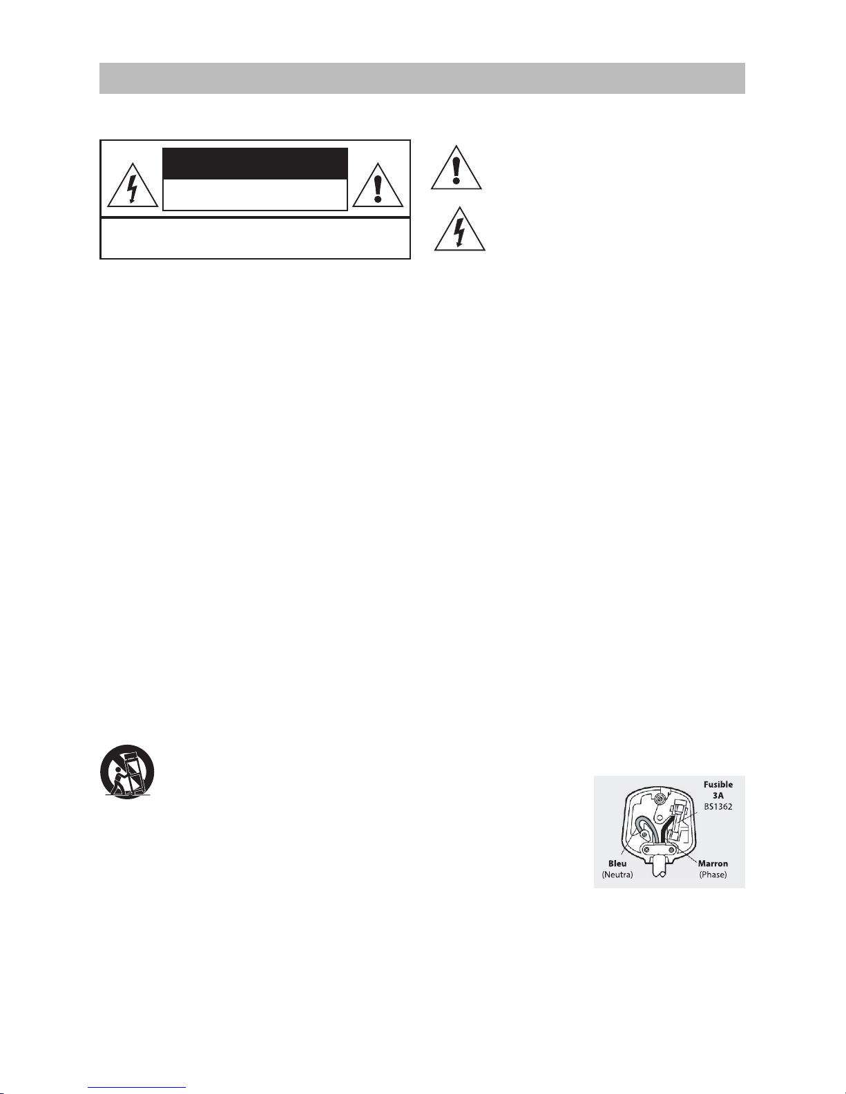
Important notice to UK users
The appliance cord is terminated with a UK approved
mains plug tted with a 3A fuse. If the fuse needs to be
replaced, an ASTA or BSI approved BS1362 fuse rated
at 3A must be used. If you need to change the mains
plug, remove the fuse and dispose of this plug safely
immediately after cutting it from the cord.
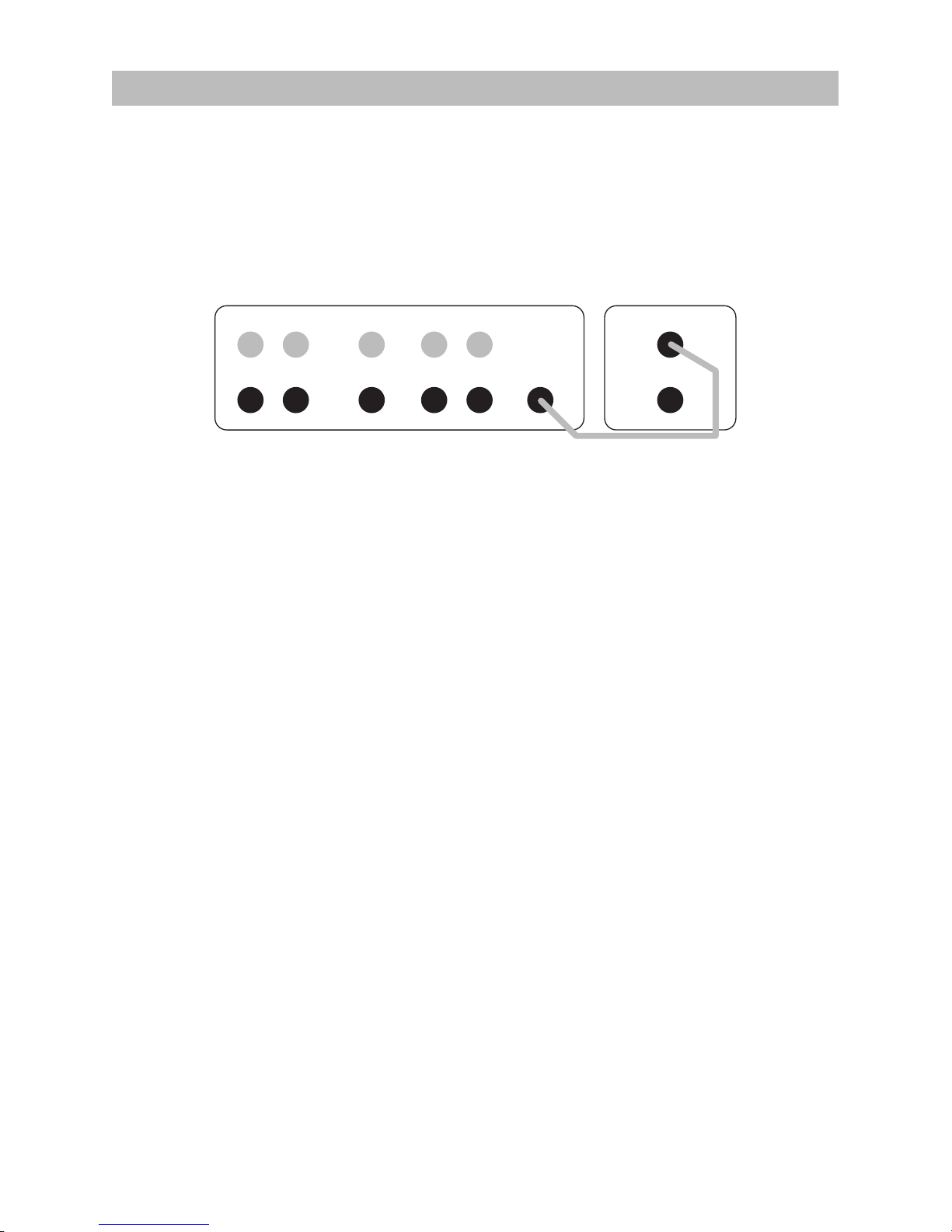
Connecting a mains plug
The wires in the mains lead are coloured in accordance
with the code: Blue: NEUTRAL; Brown: LIVE.
As these colours may not correspond to the coloured
markings identifying the terminals in your plug, proceed
as follows:
The BLUE wire must be connected to the terminal marked
with the letter N or coloured BLUE or BLACK. The BROWN
wire must be connected to the terminal marked with the
letter L or coloured BROWN or RED.
To completely disconnect
this apparatus from the
AC Mains, disconnect the
power supply cord plug
from the AC receptacle.
Where the MAINS plug
or an appliance coupler
is used as the disconnect
device, the disconnect
device shall remain
readily operable.
Safety Information
4
This symbol indicates that there are important
operating and maintenance instructions in the
literature accompanying this unit.
This symbol indicates that dangerous voltage
constituting a risk of electric shock is present
within this unit.
RISK OF ELECTRIC SHOCK
DO NOT OPEN
CAUTION
TO REDUCE THE RISK OF ELECTRIC SHOCK DO NOT REMOVE COVER (OR BACK)
NO USER-REMOVABLE PARTS INSIDE
REFER SERVICING TO QUALIFIED PERSONNEL

5
Introduction
Thank you for purchasing Q Acoustics.
This manual is intended to take you through setup and installation and will help provide optimum
performance from the product.
Please read the instructions, important safety information and warnings carefully before installation
and use, to ensure the safe and satisfactory operation of this product.
We hope you enjoy the Q Acoustics experience.
The Q Acoustics 3000 series is a range of loudspeakers designed to meet the highest expectations of
dedicated 2-channel audiophiles and discerning movie enthusiasts.
The range comprises:
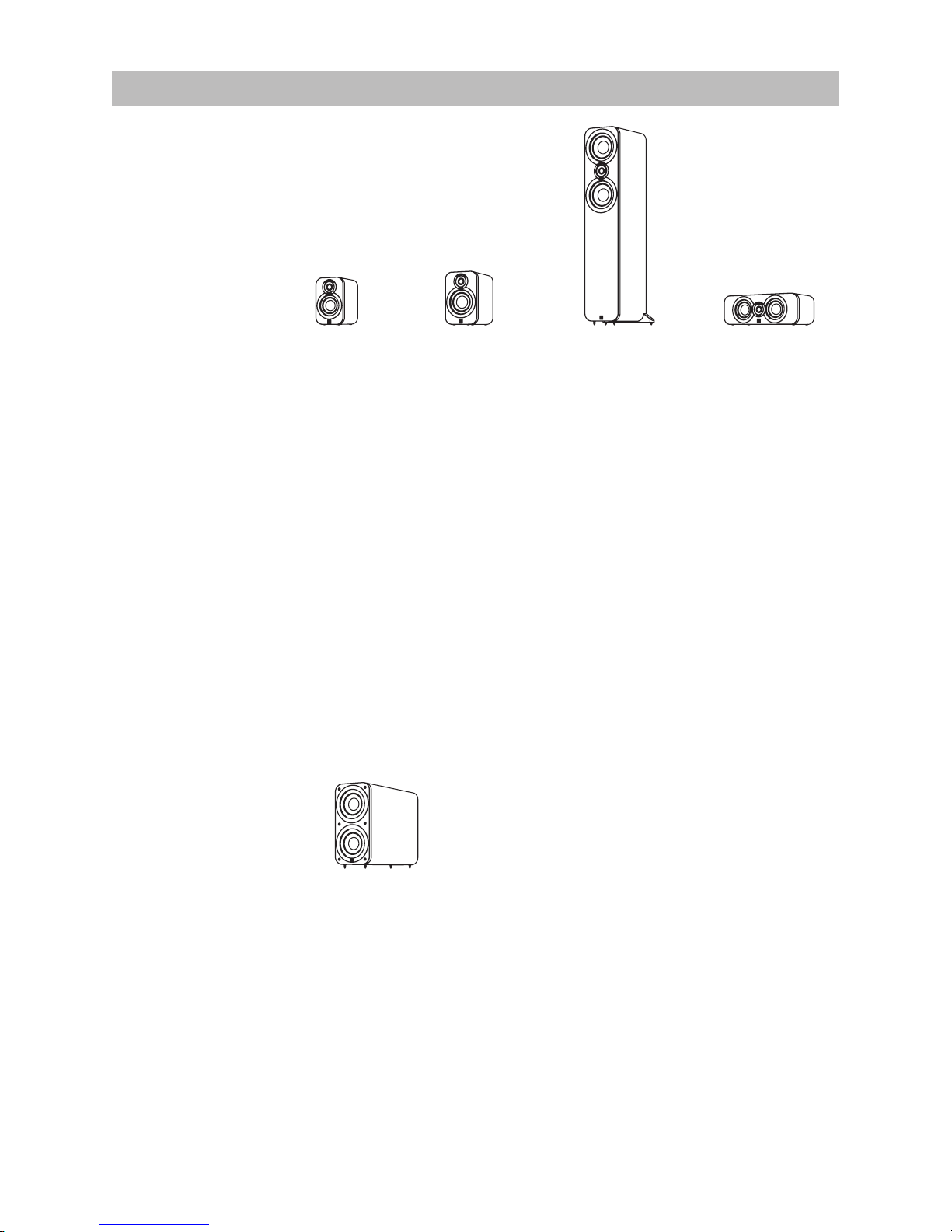
3010: Compact bookshelf speaker with a 100 mm bass driver.
3020: Bookshelf speaker with a 125 mm bass driver.
3050: Floorstander with two 165 mm bass drivers
3070S: 140 Watt active subwoofer with 2 x 165 mm drivers.
3090C: Centre channel with 2 x 100 mm bass drivers.
3050 speakers are bi-wireable. All the loudspeakers may be operated close to TV monitors with no illeects with the exception of the 3070S which should not be operated within 500mm of TV screens
monitors or other magnetically sensitive equipment. Plasma and LCD screens are unaected.
Before making any connections to your loudspeakers make sure that all active units in your system are
switched o at the mains.
When switching on your sound system or changing input sources, set the main volume control at a low
level. Turn up the level gradually.
Never play your sound system at full volume. The position of the volume control is deceptive and does
not indicate the power level of the system. Using very high volume settings may damage your hearing.
Do not connect your loudspeaker terminals to the mains supply.
Do not expose your loudspeakers to excessive cold, heat, humidity or sunlight.
If you play your loudspeakers without their grilles on, be careful to protect the drive units from damage.
Do not use makeshift stands. Fit the Q Acoustics dedicated stand according to the instructions and
using any xings provided. Your dealer will advise you.
Do not dismantle the loudspeaker. You will invalidate the warranty.
Unpacking your loudspeakers
Unpack the speakers fully. Lift the speakers from the cartons by holding the cabinets. Do not touch the
driver units or use the protective bags to lift them. The 3050 and 3070S are heavy - get assistance to lift
them if necessary.
When manoeuvring loudspeakers, do not drag them across the oor as this may cause damage - lift
them before moving them.
In the carton you will nd: The loudspeaker/s and this product manual.
In addition the packing for the following models contains:
3050: Rear stabiliser and spike covers for each speaker. An Allen key to adjust the spikes once tted.
3070S: A mains power cord or cords, spikes and spike covers.
Check the product carefully. If any items are damaged or missing, report this to your dealer as soon as
possible.
Retain the packing for future transport. If you dispose of the packing, please do so following all recycling
regulations in your area.
6
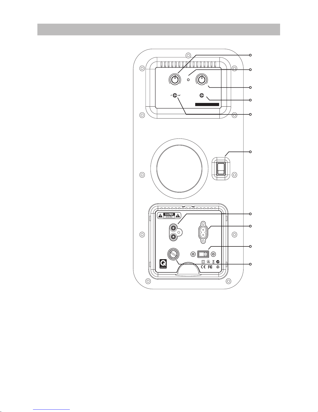
3070S Subwoofer
Level
Control
Power
Indicator
Crossover
Control
Phase
Invert
Auto On
Power
Switch
Line
Input
Mains
Input
Fuse
Voltage
LEVEL
PHASE
INVERT
AUTO ON
AUTO ON
MINM AX 50
60
80
150
AV
CROSSOVER
STATUS
Designed and engineered in the United Kingdom.
AC110-120V~60Hz
T4AL/250V
AC220-240V~50Hz
T2AL/250V
VOLTAGE
FUSE
WARNING: TO REDUCE RISK OF FIRE OR ELECTRIC SHOCK, DO NOT EXPOSE THIS
PRODUCT TO RAIN OR MOISTURE. WHEN SERVICING, USE ONLY IDENTICAL PARTS.
AVERTISSEMENT: POUR DIMINUER LE RISQUE D’INCENDIE OU DE CHOC
ÉLECTRIQUE, NE PAS EXPOSER CE PRODUIT À LA PLUIE OU À L’HUMIDITÉ.
LINE IN
LEFT /
MONO
RIGHT
3070S
www.qacoustics.co.uk
SERIAL NUMBER
Made in P.R.C
110V-120V~60Hz
220V-240V~50Hz
100 WATTS
Preliminaries
Unpack the subwoofer following
the guidelines given earlier. Before
connecting the subwoofer please
make sure that all the electronics in
your system are switched o at the
mains.
The subwoofer should be set to the
voltage in your area. Please check
before connecting to the mains
supply. If you move to an area with
a dierent voltage, be sure to set the
voltage selector to the right setting
before connection to the mains
supply!
Positioning the Subwoofer
Bass frequencies are substantially
omni directional. Although this
means that you can position the
subwoofer almost anywhere, the
stereo image will still benet by
positioning the subwoofer level
with the front loudspeakers and as
central to the listening position as
possible. This may not be feasible in a
multichannel system. If you place the
subwoofer close to a wall the bass
will be re-enforced therefore in some
locations the bass may be boomy
and indistinct.
The subwoofer should be positioned
close to a mains power source. Do
not use extension cables. Purchase a
longer power cord if necessary.
The Power Switch is the means of disconnecting this apparatus from the mains and is mounted on
the rear panel. There should be ample free space between the rear of the cabinet and any wall or
other object to allow free unrestricted access to this switch.
When positioning the subwoofer ensure the oor is sound with no loose oorboards etc. The air
movement from the subwoofer at high volumes is substantial - do not place it close to soft furnishings
or objects that may rattle. Do not place objects of any kind on the unit.

7
Operation
Setting Up and Use
Auto On: This feature enables you to switch the main system on and o without having to remember
to switch the subwoofer on and o as well.
If there is no signal input, after a few minutes the subwoofer will automatically power down into
Standby mode. This is indicated by the POWER light on the rear panel changing to red. As soon as
the subwoofer senses an input it will automatically switch into operational mode and the power light
will again glow green. Some types of music and some TV channels have very little low frequency
information in the audio signal in which case the subwoofer may not automatically switch out of
standby even though sound is coming from the other speakers in the system. If this happens then
the Auto On switch can be switched to ON making the sub-woofer stay on at all times.
Although the subwoofer can be safely left in standby mode indenitely, if you are going to be absent
from home for a long period we advise that the unit is switched o at the Power Switch.
The 3070S Subwoofer also has a fail safe heat protection system. If the amplier overheats it will shut
down momentarily and then resume operation. If this occurs check that the ventilation holes on the
control panel are not covered and that the subwoofer is not placed too close to a source of heat such
as a radiator.
8
Multi-Channel AV System
For Stereo System connection, see next section.
Connections
Standard Connection is via the Line level RCA phono Inputs. For a typical AV system set-up you will
need a single RCA phono interconnect. As this cable is likely to be quite long, make sure you get a
good quality fully screened cable. Your Q Acoustics dealer will be happy to supply you with a suitable
interconnect.
Connect the SUBWOOFER OUTPUT on the AV amplier to the L/Mono Line input on the subwoofer,
pushing the plugs rmly home to ensure a good contact.
Setting Up
Check that all system connections are properly and securely made. Ensure that the subwoofer is
switched o.
Set the controls to the following default settings:
Level Approximately half
Crossover Fully clockwise (AV setting)
Phase invert 0°
Auto on AUTO or ON
Plug the supplied power cord into the subwoofer and then into the AC supply socket. Switch on the
power at the supply socket and then switch the power switch on the subwoofer to ‘ON’. The POWER
light on the subwoofer amplier panel will glow and the subwoofer is operational.
Check the settings on your AV amplier to make sure that the sub-woofer is set to ‘ON ‘or YES. The
subwoofer level on the AV amplier should be set at its default position or 0dB. You should already
have set the speaker sizes and positions for all the other speakers in your system. If you have the
option to set the crossover frequency on the other channels make sure this is set appropriately to
your speakers. Set the distance (or delay) setting that is correct for the subwoofer position you have
chosen.
Play some stereo music you are familiar with and experiment with the Phase invert setting and level
control until you hear a seamless blend between the front speakers and the subwoofer. If you can
hear the subwoofer standing out it’s too loud!
Always bear in mind that the human ear sensitivity to bass varies enormously with the volume level,
hence the need for a wide range of programme material and sound levels.
REAR LS
RIGHT LEFT
FRONT LS
RIGHT LEFT
CENTRE LS
AV AMPLIFIER
+
-
+
-
SUB OUT
+
-
SUBWOOFER
LINE IN
LEFT /
MONO
RIGHT

9
Multi-Channel AV System
Many Home Theatre ampliers have distance settings which build in a time delay depending on the
distance of the speaker from the optimum listening position; the sweet spot. The location of the
subwoofer is one of the most important aspects of any Home Theatre system therefore getting these
settings correct will give a signicant improvement to the system’s overall performance.
Do not adjust to more than +/-0.5m from the original measured distance. If it has not been possible to
discern any improvement in the tone, try swapping the phase invert switch position on the 3070S
Subwoofer and repeat the exercise. Then re-check the sound with some stereo music again to make sure
an improvement has been noticed.
If the 3070S Subwoofer is subsequently moved relative to the other speakers reset the amplier subwoofer
distance setting to the new value and repeat the exercise. Once you are happy the optimum setting has
been achieved. The sound should be full and warm and integrated with no individual speaker being
dominant.
10
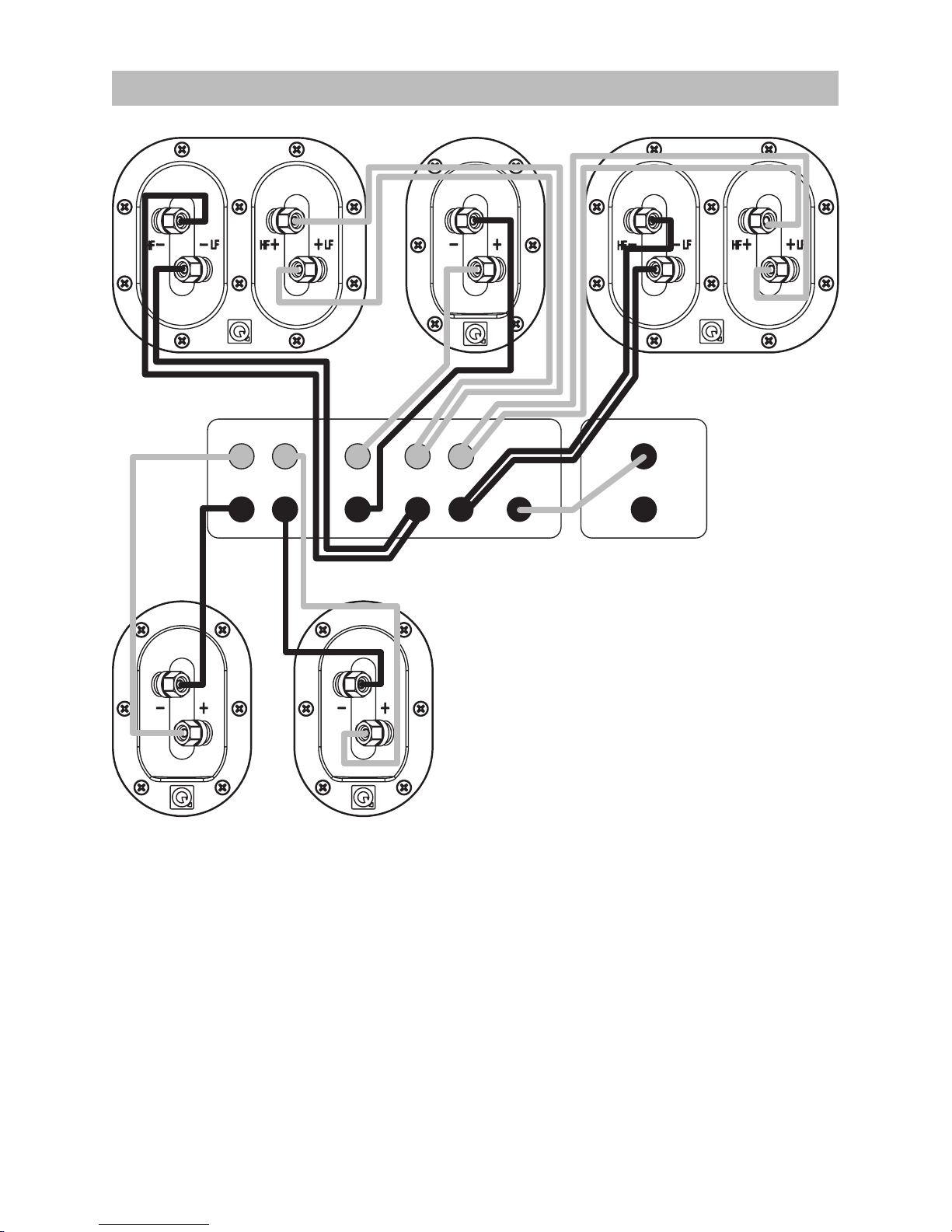
Multi-Channel AV System
The Front Speakers can be bi-wired. This is the preferred mode of connection provided the crossover
network supports bi-wiring. The Centre and Surround channel speakers are conventionally wired. 6.1
and 7.1 connections are the same as 5.1 connections with the addition of the extra eects channel/s.
When running loudspeaker cables be especially careful not to run them across open oor areas
where they could be a source of danger. Run loudspeaker cables around room boundaries whenever
possible. Line level signal cables should be run away from mains cables. Never run line level signal
cables parallel to power cables especially on long runs.
If the subwoofer is triggered on by appliances switching on and o, re-route the input signal cable
before taking further measures.
REAR LS
RIGHT LEFT
FRONT LS
RIGHT LEFT
CENTRE LS
AV AMPLIFIER
FRONT RIGHT
SURROUND RIGHT SURROUND LEFT
CENTRE FRONT LEFT
+
-
+
-
SUB OUT
+
-
SUBWOOFER
LINE IN
LEFT /
MONO
RIGHT
11
Multi-Channel AV System
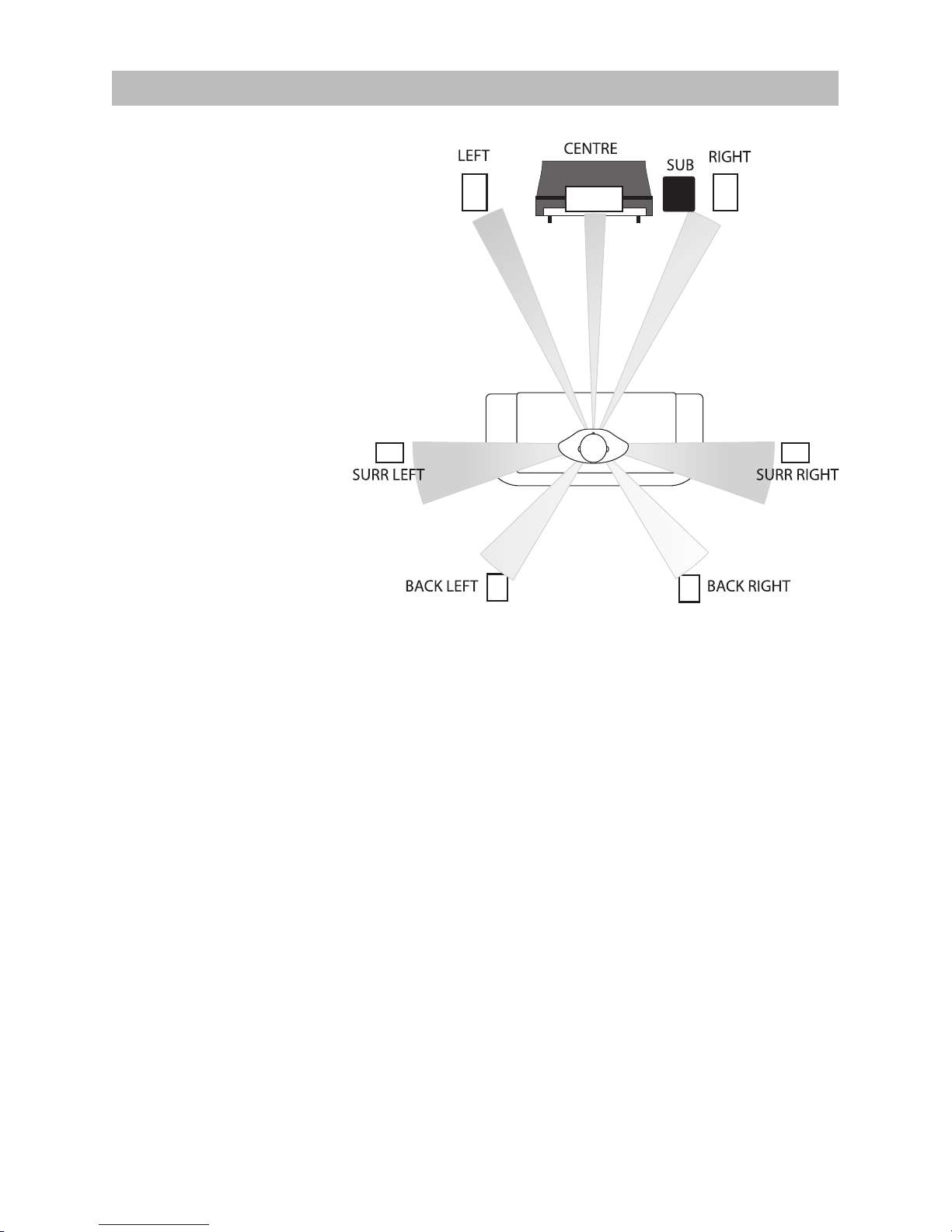
Placement: The Front and
Centre speakers should be
in line. If this is not possible,
consult your processor manual
for guidance on adjusting
relative centre / front delay
times. If you have a 5.1 system,
the listening seat can be closer
to the rear wall. As always, be
prepared to experiment.
Bass Management:
AV processors oer the choice
of ‘Large’ or ‘Small’ for the
speakers. If you choose ‘Large’
the speaker receives the full
frequency. Choose ‘Small’
and the bass is sent to the
Subwoofer. We recommend
you choose ’Small’ for the
3090C and the 3010 and 3020
wherever they are used in the
system. The 3050 should be
set to ‘Large’. The subwoofer
option should be enabled (set
to ‘ON’ or ‘YES’)
Levels: When the basic system parameters have been established, put your processor into the ‘setup’
routine. Set up each individual speaker so that the level is the same at the listening position as all the
others. If your processor enables you to adjust the delay times, follow the instructions closely as this
will profoundly aect the nal result. When you play a movie you may think the rear channels are too
soft - they aren’t! You may however have to adjust the subwoofer level both at the processor and at
the subwoofer. Once set, do not re-adjust these levels.
LFE: The LFE channel sends all the bass sound eects to the subwoofer. If speakers are set to ‘Small’ ,
system bass from those channels is also sent to the subwoofer. If you play the system at extreme levels
and / or have the subwoofer level set too high you may overdrive the subwoofer with unpleasant
sonic results. If this occurs, reduce the level immediately.
Phase: If your speakers are incorrectly wired the bass will be blurred and thin. In this case, check the
wiring carefully. If your speaker wire has a tracer along one core, consistently use the striped core to
connect all the positive (RED) terminals. In this way the system will always be in phase.
Always follow the instructions in your AV processor manual!
Above is the Dolby Labs recommended layout for 7.1systems. The 6.1 layout is the
same except a single central speaker replaces the two back units. The 5.1 layout has
no back speakers
0º
-
3
0
2
º
º
2
9
0
º
-
1
1
0
º
1
5
0
º
-
1
3
5
º
12
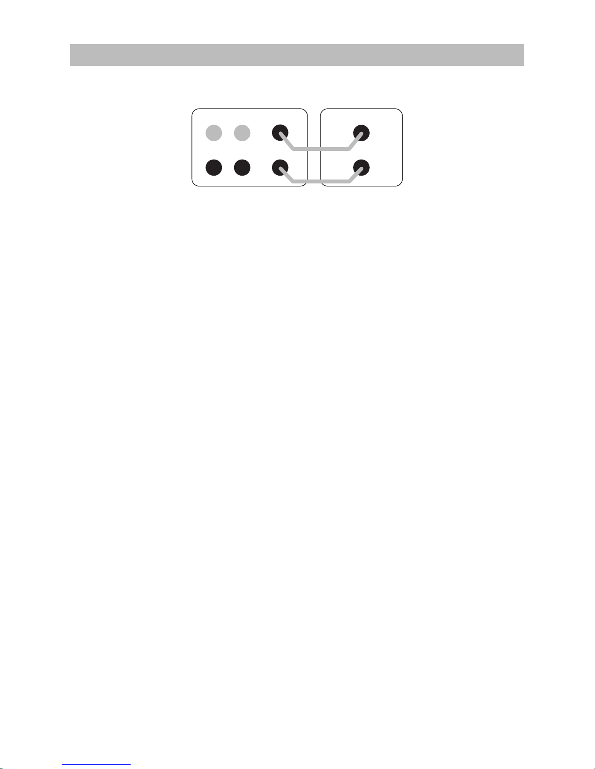
Stereo System
Connections
Connect a good quality stereo RCA phono lead to the L and R inputs on the 3070S and connect the other
end to the PRE OUT sockets on the rear of the amplier.
The subwoofer will automatically add the L and R signals together so that no information is missed. If you
wish to use two subwoofers then you can run a single RCA phono cable to each subwoofer and thus have
a stereo subwoofer system.
Ensure that the L output on the amplier goes to the left hand side subwoofer and R to the right hand side
to preserve the stereo image of the main speakers. The subwoofers will need to be placed close to their
respective main speakers and the set-up will need to be done separately for each subwoofer.
FRONT LS
RIGHT LEFT
STEREO AMPLIFIER
L
R
PRE OUT
+
-
SUBWOOFER
LINE IN
LEFT /
MONO
RIGHT

13
Stereo System
Setting Up
Check that all system connections are properly and securely made. Ensure that the subwoofer is
switched o. Set the controls to the following default settings:
Level Approximately half
Crossover Minimum (50Hz) for large oorstanders and halfway (100Hz) for
bookshelf or small speakers
Phase invert 0°
Auto on AUTO or ON
Plug the supplied power cord into the subwoofer and then into the AC supply socket. Switch on the
power at the supply socket and then switch the power switch on the subwoofer to ‘ON’. The POWER
light on the subwoofer amplier panel will glow and the subwoofer is operational.
Play some music you are familiar with and experiment with the Phase invert setting and level control
until you hear a good blend between the front speakers and the subwoofer. If you can hear the
subwoofer standing out it’s too loud!
Always bear in mind that the human ear’s sensitivity to bass varies enormously with the volume level,
hence the need for a wide range of programme material and sound levels. Once you are happy with
the sound you can then ne tune the performance by using the remaining controls.
Crossover: The crossover control determines at what frequency your subwoofer output begins to
rapidly diminish. This should be set so that it corresponds with the frequency your main speakers
begin to produce a strong output by themselves. The adjustment allows for a smooth handing over
between subwoofer and main speaker output. If this setting is too low there will be a ‘hole’ in the
sound where certain frequencies are weak, conversely if it is too high there will be an exaggeration
of certain frequencies producing an overpowering bass. You can get an idea of the correct setting
from your main speakers specication sheet, look for the lowest frequency that the speaker produces
(the “-3dB point”) under the “Frequency response” heading. Room positioning has a dramatic eect
on low frequency reproduction of both the subwoofer and your main speakers so don’t be worried
if you nd you require a setting which does not correlate with the specied low frequency point of
your main speakers.

14
Care and Cleaning
Warranty
Cabinet Care
Clean cabinets with a dry cloth. Do not use solvent based cleaning materials. If the cabinets become
stained, remove the stain with a cloth lightly moistened with water, white spirit or isopropyl alcohol
depending on the stain. Then lightly bu with a cloth to remove any residue of the cleaning agent.
Never use abrasives of any kind.
Grilles
Lightly brush out grilles with a soft brush.
Drive Units.
Drive units are best left untouched as they are easily damaged when exposed.
Q Acoustics loudspeakers are warranted free of defects in materials and workmanship as follows:
Passive Loudspeakers: 5 years from the date of purchase
Active Loudspeakers & Subwoofers: 2 years from the date of purchase
During the warranty period Q Acoustics will, at its option, repair or replace any product found to be
faulty after inspection by the company or its appointed distributor or agent.
Misuse and fair wear and tear are not covered by warranty.
Within the warranty period faulty units should be returned to the supplying dealer. Q Acoustics does
not support an International Warranty and if it is not possible to return to the supplying dealer please
contact Q Acoustics for advice.
Items that cannot be taken in for repair must be sent carriage paid, preferably in the original packing,
and with the proof of purchase. Damage sustained by goods in transit to the repair centre is not
covered by warranty. Return carriage for items covered by the warranty will be paid by Q Acoustics or
their distributor or agent as appropriate.
This warranty does not in any way aect your legal rights.
For service information In other countries contact: info@qacoustics.co.uk
Q ACOUSTICS
Armour Home Electronics Ltd.
Stortford Hall Industrial Park
Bishops Stortford, Herts, UK
CM23 5GZ

15
Q Acoustics 3000 Series Accessories
3010 / 3020 / 3090C Wall Bracket (Single)
Black and White
3010 / 3020 Speaker Stand (Pair)
Black or White
650 mm
300 mm
260 mm
35° 35°
5 - 45mm
40° 40°
5 - 45mm
45°
3010 3020
Q Acoustics 3000 Series Specifications
16
Passive Loudspeakers
Enclosure type:
Bass unit (mm):
Treble unit (mm):
Frequency response
(+/-3dB):
Nominal impedance:
Sensitivity (2.83v@1m):
Recommended
amplier power:
Crossover frequency:
Eective volume:
Cabinet dimensions
(WxHxD mm):
Weight (per cabinet):
Active Subwoofer
Enclosure type:
Bass unit (mm):
Amplier power:
Crossover frequency:
Cabinet dimensions
(WxHxD mm):
Weight:
3010
2-way reex
100 mm
25 mm
68 Hz - 22 kHz
6 Ω
86dB
15 - 75W
2.8 kHz
3.8 litres
150 x 235 x 200
3.6 Kg
3070S
Ported
2 x 165 mm long throw
140W rms
50 Hz - 150 Hz (var.)
200 x 400 x 425
13.6 Kg
3020
2-way reex
125 mm
25 mm
64 Hz - 22 kHz
6 Ω
88dB
25 - 75W
2.9 kHz
5.9 litres
170 x 260 x 226
4.6 Kg
3050
2-way reex
2 x 165 mm
25 mm
44 Hz - 22 kHz
6 Ω
92dB
25 - 100W
2.6 kHz
35.6 litres
200 x 1000 x 298
17.8 Kg
3090C
2-way reex
2 x 100 mm
25 mm
75 Hz - 22 kHz
6 Ω
89dB
25 - 100W
2.7 kHz
10.3 litres
430 x 150 x 200
6.0 Kg
FR
Conçu et fabriqué au Royaume-Uni.
Manuel de l'utilisateur et spécication des produits
Série 3000
Modèle : Q3070S
INFORMATIONS IMPORTANTES - VEUILLEZ LIRE ATTENTIVEMENT
Lire attentivement ces instructions.
Conserver soigneusement ces instructions.
Veuillez prendre garde à tous les avertissements.
Veuillez suivre toutes le instructions.
Ne pas utiliser ce produit à proximité d’eau.
Le nettoyer uniquement à l’aide d’un chion sec.
Ne pas bloquer les ouvertures d’aération.
Suivre les instructions du fabricant pour l’installation.
Ne pas installer le produit près de sources de chaleur telles
que des radiateurs, des bouches de chaleur, des poêles
ou d’autres appareils (notamment des amplicateurs)
produisant de la chaleur.
Ne pas interférer avec l’objectif sécuritaire de la che
polarisée ou de mise à la terre. Une che polarisée
comporte deux lames, dont l’une est plus large que
l’autre. Une prise de mise à la terre possède également
deux lames ainsi qu’une troisième broche. La lame la plus
large ou la troisième broche sont présentes à des ns de
sécurité. Si la che fournie n’est pas adaptée à votre prise
de courant murale, prendre contact avec un électricien
an de remplacer la prise obsolète.
Protéger le cordon d’alimentation secteur an qu’il ne soit
ni piétiné ni pincé, en particulier au niveau des ches, des
prises de courant et du point de sortie du matériel.
Utiliser uniquement les équipements et accessoires
spéciés par le fabricant. Utiliser uniquement avec un
chariot, un pied, un tripode, des xations murales ou une
table répondant au spécications fournies par le fabricant
ou vendus avec l’appareil.
En cas d’utilisation d’un chariot, prendre garde
en déplaçant l’ensemble chariot/appareil
d’éviter les blessures causées par une chute.
Débrancher le système lors des orages ou lorsqu’il reste
inutilisé pendant de longues périodes.
Coner toute réparation à un technicien qualié.
Des réparations sont nécessaires si le produit a été
endommagé d’une façon ou d’une autre, par exemple si
le cordon ou la che d’alimentation sont endommagés, si
du liquide a été renversé sur le produit ou si des objets
sont tombés dessus, si le produit a été exposé à la pluie ou
à l’humidité, ou bien s’il ne fonctionne pas normalement
ou s’il est tombé.
Avertissement: An de réduire les risques d’incendie ou
d’électrocution, ne pas exposer ce produit à la pluie ou à
l’humidité. Ce produit ne doit pas être exposé aux gouttes
ou aux éclaboussures et aucun objet rempli de liquide, tel
qu’un vase de eurs, ne doit être posé dessus.
Ne placer aucune source de amme nue, par exemple une
bougie, sur le produit.
Avertissement: L’interrupteur secteur du caisson de
graves est l’élément qui sert à déconnecter l’unité de la
source d’alimentation secteur. Celui-ci est situé sur le
panneau arrière. Pour permettre un accès facile à cet
interrupteur, l’appareil doit être placé dans un endroit
ouvert et non obstrué ; l’interrupteur doit pouvoir être
opéré librement.
Attention: Les changements ou modications qui n’ont
pas été expressément approuvés par le fabricant peuvent
révoquer le droit d’usage de ce produit.
Service après-vente: Le matériel à réparer doit être
renvoyé au revendeur ou au service après-vente de votre
région. Les adresses des principaux agents de service au
Royaume-Uni sont indiquées dans ce manuel.
Tierces parties: Dans le cas peu probable où ce produit
serait transmis à un tiers, ces instructions devront
également lui être remises.
Remarque importante concernant les utilisateurs du
Royaume-Uni:
Le cordon d’alimentation Royaume-Uni (RU) se termine
par une che homologuée pour le secteur RU équipée
d’un fusible de 3A. Si ce fusible a besoin d’être remplacé,
un fusible ASTA ou BSI conforme BS1362 d’une valeur
nominale de 3 A devra être utilisé. Si la che principale
doit être changée, enlever le fusible et jeter la prise en
respectant toutes les règles de sécurité après l’avoir
sectionnée du cordon.
Connexion aux prises secteur
Les ls contenus dans le cordon d’alimentation se
distinguent suivant le code couleur suivant: Bleu: NEUTRE;
marron: PHASE.
Étant donné que ces
couleurs pourraient ne pas
correspondre aux marqueurs
colorés distinguant les
bornes de votre che, voici la
marche à suivre :
Le l BLEU doit être connecté
à la borne marquée de
la lettre N ou colorée en
BLEU ou en NOIR. Le l MARRON doit être connecté à la
borne marquée de la lettre L ou colorée en MARRON ou
en ROUGE.
Pour déconnecter complètement l’appareil du secteur,
déconnecter la che du cordon d’alimentation de la prise
secteur.
Lorsque la che SECTEUR ou un coupleur est utilisé
comme dispositif de déconnexion, l’appareil déconnecté
demeurera prêt à l’emploi.
Consignes de sécurité
18
Ce symbole indique que la documentation
accompagnant le produit contient des
instructions importantes relatives à son
fonctionnement et son entretien.
Ce symbole indique qu’une tension dangereuse
présentant un risque d’électrocution
existe au sein de ce produit.
RISQUE DE CHOC ÉLECTRIQUE
NE PAS OUVRIR
ATTENTION !
POUR RÉDUIRE LES RISQUES DE CHOC ÉLECTRIQUE, NE PAS
ENLEVER LE COUVERCLE (NI LE PANNEAU ARRIÈRE)
CE PRODUIT NE CONTIENT PAS D’ÉLÉMENTS MANIPULABLES PAR L’UTILISATEUR
S’ADRESSER À DES PROFESSIONNELS QUALIFIÉS
 Loading...