


01 00 i Series
EN
FR
IT
ES
DE
EL
User Manual and
Product Specifications
ZH
RU

Important Information- Please Read Carefully
CAUTION!
RISK OF ELECTRIC SHOCK
DO NOT OPEN
TO REDUCE THE RISK OF ELECTRIC SHOCK DO NOT REMOVE COVER (OR BACK)
Readtheseinstructions. When a cart isused, usecaution whenmoving thecart/ apparatus
Keeptheseinstructions.
Heedallwarnings.
Followallinstructions.
Donotusethis apparatusnearwater.
Cleanonlywithdry cloth.
Donotblockany ventilationopenings.
Installinaccordancewith themanufacturer'sinstructions.
Do notinstall nearanyheatsourcessuch as radiators,heat registers,
stoves,orotherapparatus (includingamplifiers)thatproduce heat.
Do not defeatthe safetypurpose ofthe polarizedor groundingtype
plug. Apolarized plug hastwobladeswith one widerthantheother.
A groundingtype plughastwoblades andathirdgrounding prong.
The widerbladeor the thirdprongareprovided for yoursafety.Ifthe
provided plug doesnot fitinto youroutlet, consultanelectrician for
replacementoftheobsolete outlet.
Protectthepowercordfrombeing walked onor pinched, particularly
at plugs, convenience receptacles, and the point where they exit
fromtheapparatus.
Useonlyattachments/accessoriesspecified bythemanufacturer.
Useonlywitha cart,stand,tripod,bracket, ortable
specified by the manufacturer, or sold with the
apparatus.
NO USER-REMOVEABLE PARTS INSIDE
REFER SERVICING TO QUALIFIED PERSONNEL
combinationtoavoidinjury fromtip-over.
Unplug this apparatus during lightning storms or when unused for
longperiodsoftime.
Referallservicingto qualifiedservice personnel.Servicing isrequired
when the apparatus has beendamaged in anyway, such as power
supply cord or plug is damaged, liquid has been spilled or objects
have fallen into the apparatus, the apparatus has been exposed to
rainormoisture,does notoperate normally,orhas beendropped.
Warning:Toreduce the riskoffireorelectricalshock,donot expose
this productto rainormoisture.The productmustnot beexposedto
dripping and splashing and no object filled with liquids such as a
vaseofflowers should beplacedonthe product.
No naked flame sources such as candles should be placed on the
product.
Warning: The mains power switch for the subwoofer is the device
used to disconnect the unit from the mains supply. This switch is
located on the rear panel. To permit free access to this switch, the
apparatusmustbelocated inanopenarea withoutanyobstructions,
andtheswitchmust befreelyoperable.
Caution: Changes or modifications not expressly approved by the
manufacturercouldvoidthe user'sauthoritytooperate thisdevice.
Service: Equipmentforsevicingshouldbe returned tothe supplying
dealer, or to the service agent for your area. The addresses of the
This symbol indicates that there are important operating and
maintenanceinstructionsinthe literature accompanyingthisunit.
This symbol indicates that dangerous voltage constituting a risk of
electricshockispresent within thisunit.
mainServiceAgentsfor theUKarelisted inthismanual.
Third parties: In theunlikelyeventthat you passthisproductonto
athirdparty,include theseoperatinginstructionswith theproduct.
Important notice to UKusers
The appliance cord is terminated with a UK approved mains plug
fitted witha 5A fuse.If
approved BS1362 fuse rated at 5A must be used. If you need to
change the mains plug, remove the fuse and dispose of this plug
safelyimmediatelyaftercutting itfromthecord.
Connecting a mains plug
The wires in the mains lead are coloured in accordance with the
code: Blue: NEUTRAL; Brown:LIVE:
As these colours may not correspond to the coloured markings
identifyingtheterminalsin yourplug,proceedas follows:
The BLUE wire must be
connected to the
terminal marked with
the letter N or coloured
BLUE or BLACK. The
BROWN wire must be
connected to the
terminal marked with
theletterLor colouredBROWNorRED.
the fuseneeds to bereplaced,an ASTA orBSI
5A FUSE
BS 1362
BLUE
(Neutral)
BROWN
(Live)

Q Acoustics 1000i Series
Introduction
The Q Acoustics 1000i series is a range of loudspeakers designed to meet
the highest expectations of dedicated 2-channel audiophiles and
discerningmovieenthusiasts.The range comprises:
1010i: Compact Bookshelf speaker witha100mmbass driver.
1020i: Bookshelf speaker with a125mmbassdriver.
1030i: Compact Floorstander with a 165mm bass driver
1050i: Floorstander with two 165mmbassdrivers
1000Ci: Centre channel withtwo100 mm bass drivers, which canbewall
mounted if required.
1000Si: 100 Watt active subwoofer with a 200 mm driver and signal
sensing for automatic power on/off.
All the passive speakers are bi-wireable with the exception of the 1010i
and 1000Ci.
All the loudspeakers may be operated close to TV monitors with no illeffects with the exception of the 1000Si, which should not be operated
within 500mm of TV screens monitors or other magnetically sensitive
equipment. Plasma and LCD screensareunaffected.
Before making any connections to your loudspeakers make sure that all
active units in your system are switched off at the mains.
When switching on yoursoundsystem or changing input sources, set the
main volume control at alowlevel.Turn up the level gradually.
NEVER play your sound system at full volume. The position of the
volume control is deceptive and does not indicate the power level of the
system. Using very high volumesettingsmaydamageyour hearing.
DO NOT connect your loudspeakerterminalstothemains supply.
DO NOT expose your loudspeakers to excessive cold, heat, humidity or
sunlight.
If you play your loudspeakers withouttheir grilles on, be careful to protect
the drive units from damage.
DO NOT use makeshift stands. Fit the Q-Acoustics approved stand
according to the instructions and using any fixings provided. Your dealer
will advise you.
DO NOT dismantle the loudspeaker. You will invalidate the warranty.
Unpacking your loudspeakers
Unpack the speakers fully. Lift the speakers from the cartons by holding
the cabinets. Do notuse the polythene bags to lift them.The1030i, 1050i,
and 1000Si are heavy -getassistancetolift them if necessary.
When manoeuvring loudspeakers, do not drag them across the floor as
this may cause damage -liftthembeforemoving them.
In the carton youwillfind: The loudspeaker/s and this productmanual.
In addition the packing for the followingmodels contains:
1030i and 1050i: A plinth for each speaker, screws, an Allen key to
attach the stand and asetoffloorspikes and spike covers.
1010i, 1020i, 1000Ci: A set of four adhesivefeet.
1000Si: An IECpowercord suitable for the mains supply in yourarea.
Check the product carefully. If any items are damaged or missing, report
this to your dealer assoonaspossible.
Retain the packing for future transport. If you dispose of the packing,
please do so following allrecyclingregulationsinyour area.
Preparation
Spikes are sharp. Exercise care!
Never place a spiked loudspeaker where it can cause damage!
Always move your loudspeakers by lifting them - never drag them!
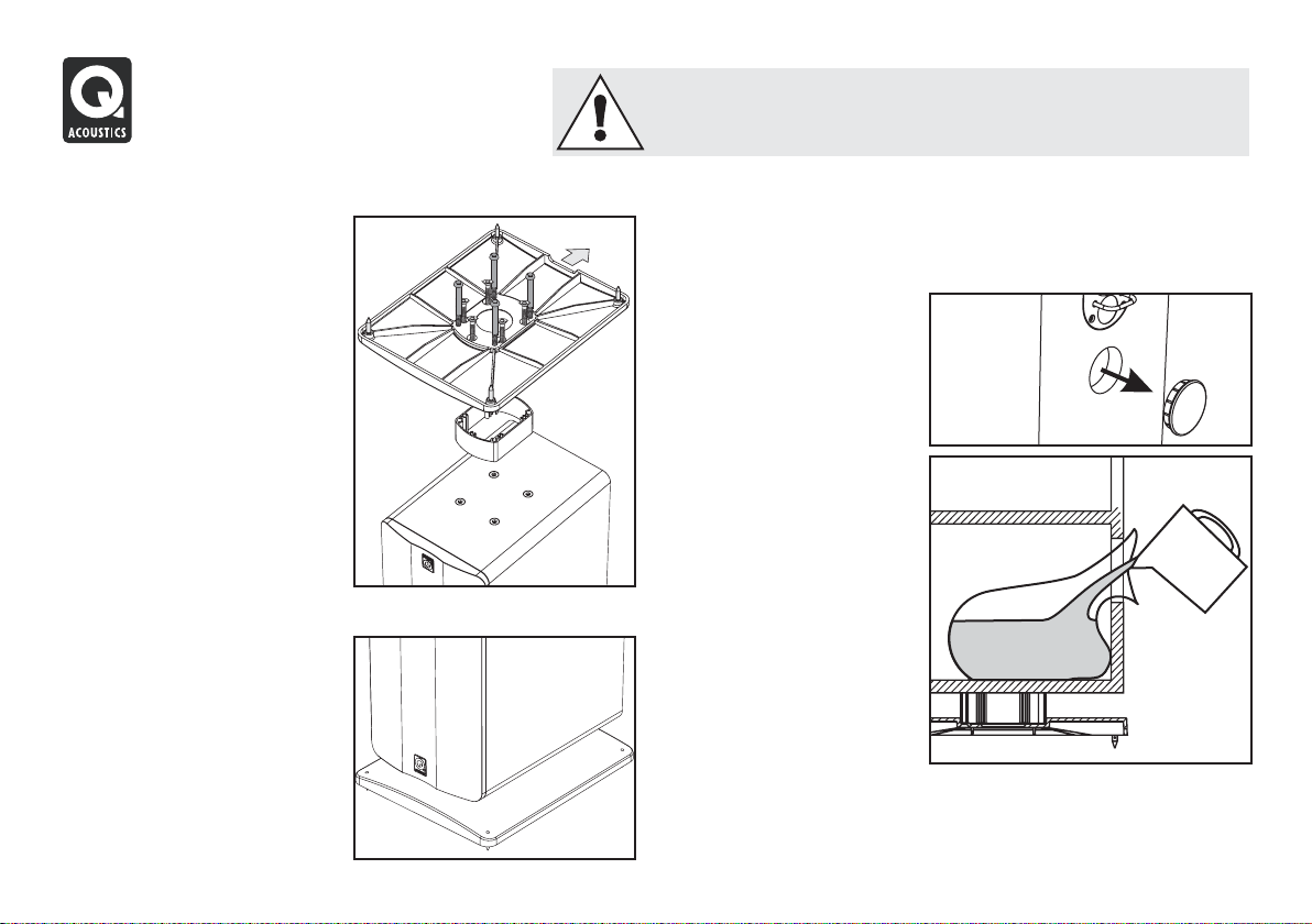
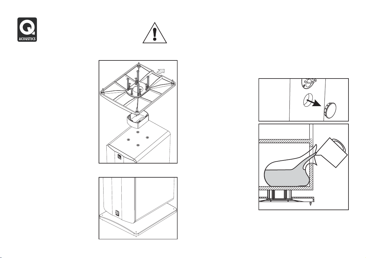
Fitting the Floor StandandSpikes- 1030i and 1050i Sand Filling the 1030i
Place a soft cloth or towel on the The lower chamber of the 1030i can be filled with sand to aid stability and
floor. Invert the loudspeaker and to dampen acoustic vibration. This is entirely at your option. No harm is
place it on the cloth. caused if you omit thisprocedure.
The stand consists of a base and a
pillar. Attach the base to the pillar
with the five short screws. An Allen is idea l. Do not use
key is provided so you can tighten building sand.
the screws properly.
Invert the stand and thread the four
long bolts through the base and
the pillar; line up the bolts with the
mounting holes in the bottom of
the speaker and tighten securely.
Make sure the recess in the stand
faces the rear of theloudspeaker.
Thread the spikes half way into the
base and returntheloudspeaker to
the upright position. (If you have a
wood or stone floor push a spike
protector over each spike before
turning the speaker upright)
When the speaker is the right way
up, insert the Allen key into each
spike from the top and adjust all
the spikes in and out until the
loudspeaker is level and stable.
Youwill need:
l5kg of dry sand - play sand
lA large, strong polythene
bag.
lA dry pouring jug.
Remove the bung in the rear
panel. Push the bag into the
chamber with the mouth of
the bag protruding at least
100 mm. Carefully pour (or
spoon) the sand into the bag.
When all the sand is in the
bag tie the mouth securely
and push the bag into the
chamber. Replace the bung.
1010i, 1020i,1000Ci
Each loudspeaker is
provided with four adhesive feet. If you are not wall mounting the
speakers, peel the backing off each foot and press a foot into place at
each corner of the bottompanel15mmin from each edge.
Positioning Passive Loudspeakers
Dolby and the double-D symbol are
trade marks of Dolby Laboratories.
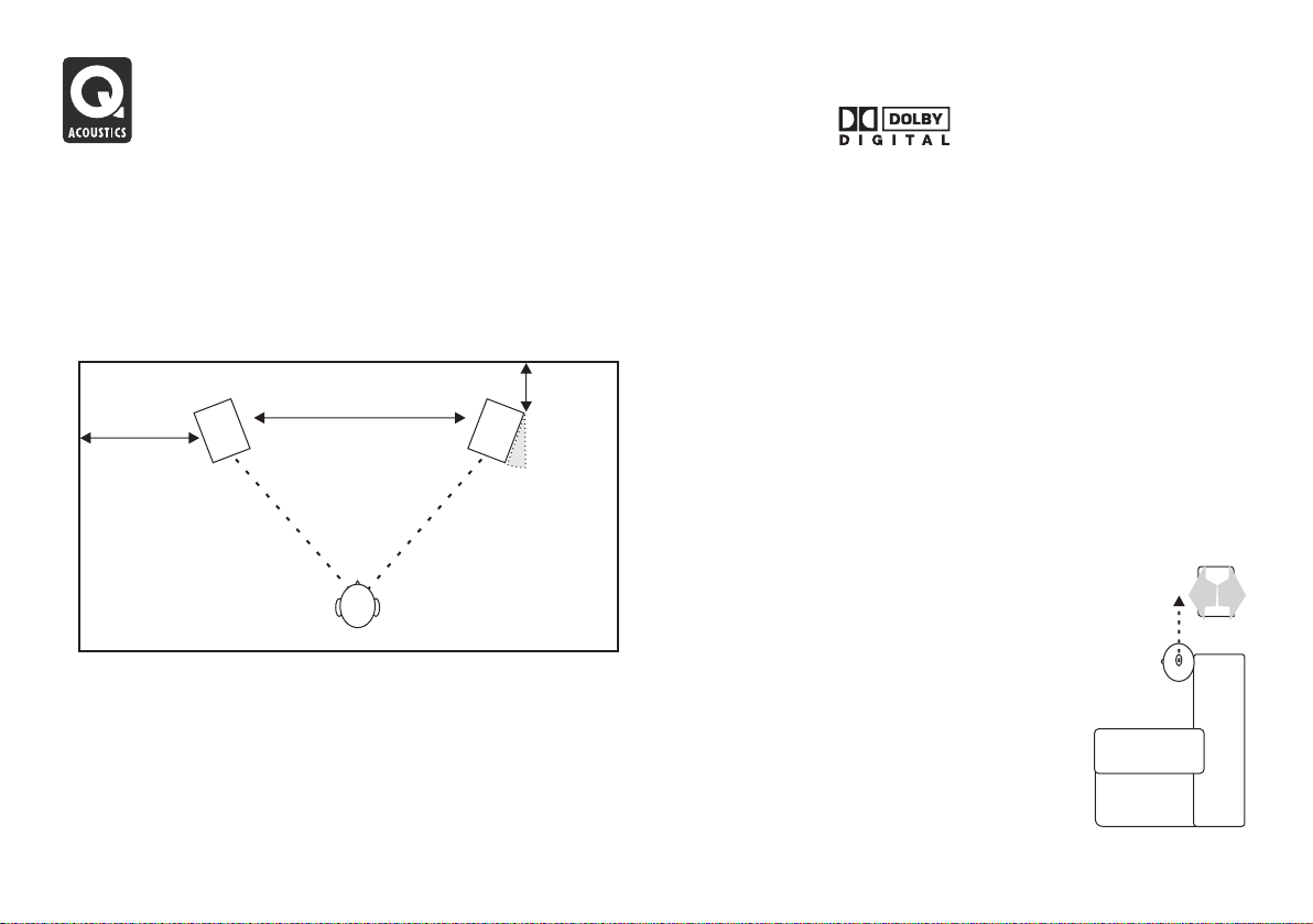
1030i and 1050i
The 1030i and 1050i loudspeakers should be positioned at least 200mm
from a back wall and 500mm from the side walls. Placing the speakers
closer to the wall will increase bass but could cause the sound to boom
and lack precision and detail. Thespeakers should be 2m- 4m apart and
central to the seated listener. Turning the speakers slightly inwards will
sharpen a stereo image butmaycausenarrowingof the sound source.
>200mm
2m-4m
>500mm
0-30°
2m-4m
1010i and 1020i
The 1010i and 1020i are ideally mounted on Q-Acoustics floor stands or
wall mounted. If you are stand mounting, a simple guide is that the treble
unit should be at ear level to a seated listener. Wall mounted speakers
may be mounted slighter higher with the speaker angled down. Stand
mounted speakers should be treated as floorstanding speakers except
that the speaker may be placed a little closer to the back wall. Shelf
mounting is also possible.
An optional bracket designed specifically to wall mount the Q Acoustics
1010i, 1020i and1000Ci is available from yourdealer. Floorstandsfor the
1010i and 1020i are alsoavailable.
Be prepared to experiment to find the best setup for your taste in your
particular listening room.
Effects loudspeakers
1000Ci
The 1000Ci is designed to be operated close to a TV screen and central
to it. It should be placed immediately above or below the screen. If you
are using aregular TV set, make surethat the TV is capableof adequately
supporting the speaker andhasa level top. If not, considerplacing the TV
on a cabinet with the1000Cionasecure shelf immediately below the TV.
If you have a Plasma or LCD monitor, mount the 1000Ci to the wall or
other suitable surface immediate ly above or below
the screen.
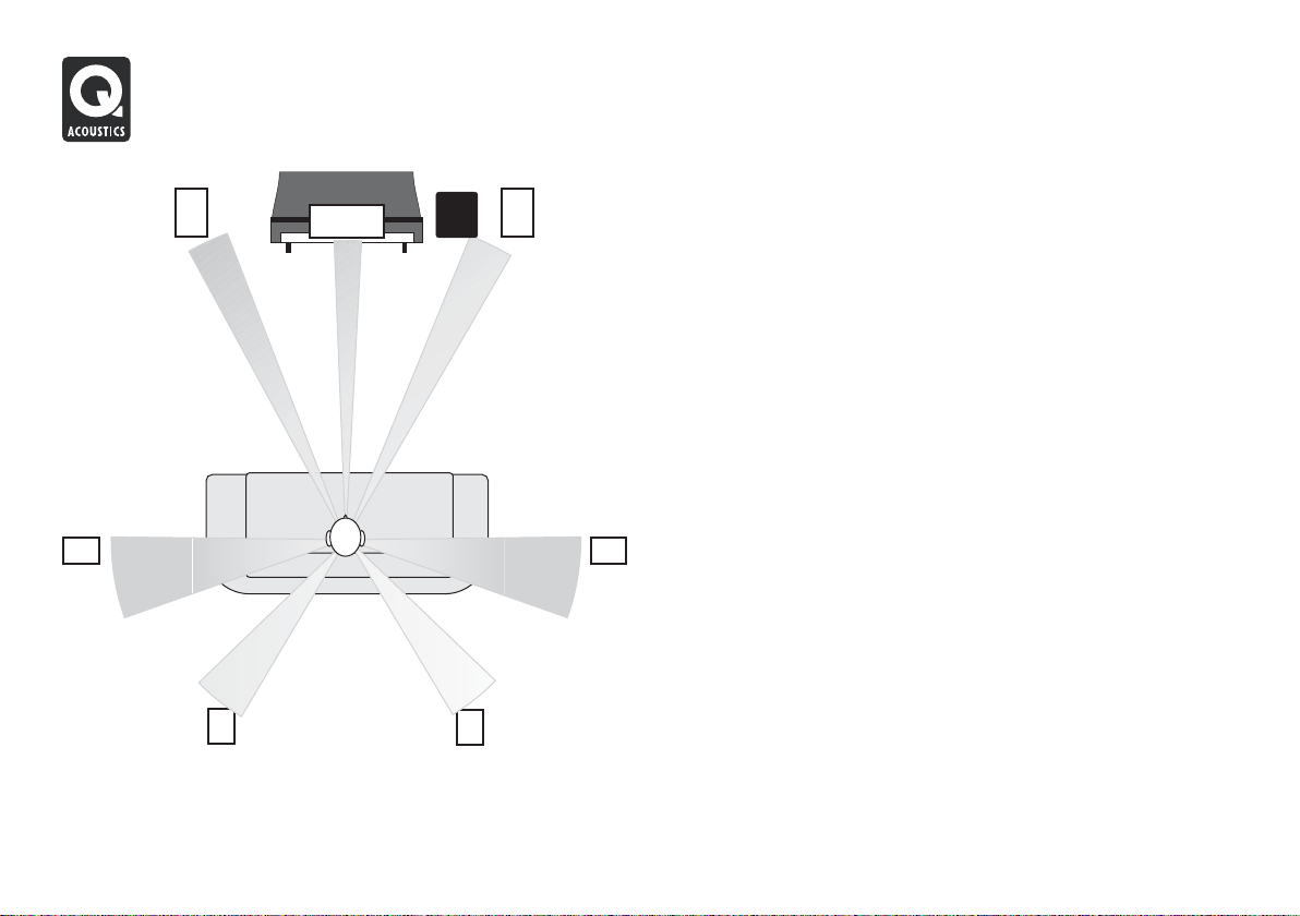
Surround Speakers
There are recommendations from Dolby labs for
5.1 effects speakers.
Surround speakers should be mounted on either
side of the listener, slightly behind the listening
position. The speakers should be sited facing
inward either mounted on the side walls of the
room or if the room is large, on high stands and
with their centres above ear level to a seated
listener.
400mm
Connecting Passive Loudspeakers
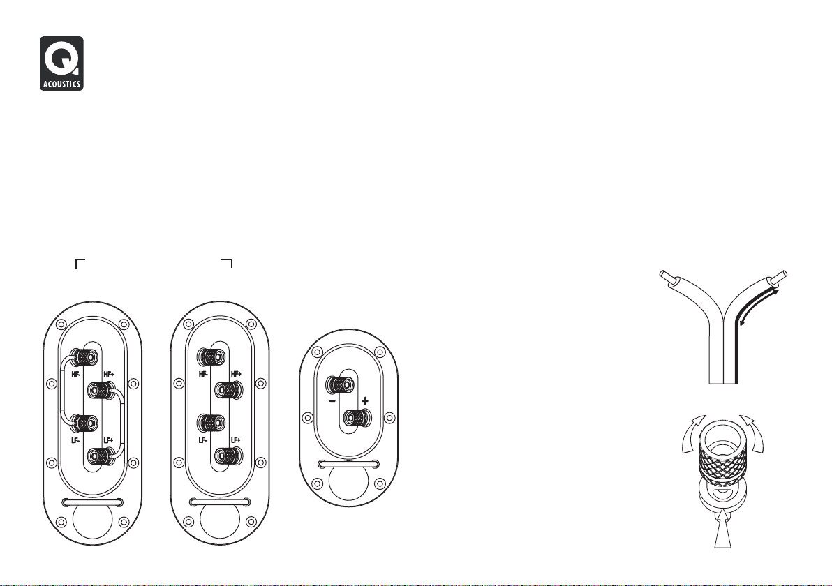
Terminals and Connectors Loudspeaker Cables
The 1020i, 1030i and 1050i are bi-wireable. A bi-wireable crossover has Specialist loudspeaker cables will offer a higher standard of
four terminals. The upper pair of terminals connects to the treble (HF) reproduction than general purpose ‘bell’ or ‘zip’ wire. Use cable with
speaker and the lower pair to the bass (LF) speaker/s. As supplied the generous amounts of copper for the front and centre channels. Thin
crossovers are fitted with removable links to connect the terminal pairs. cables reduce the bass and restrict the dynamic range. Surround (rear)
This permits you to connect the loudspeaker conventionally using one channels arelesscritical.
pair of cables or inbi-wiredmodewithtwo pairs.
The 1010i and 1000Ci have standardtwoterminalcrossovers. connected to the positive terminals. The cables connecting the amplifier
1020i, 1030i, 1050i
Standard
Connection
Bi-Wired
Connection
1010i, 1000Ci
.
Speaker cable has a stripe or tracer along one core. By convention this is
to the front loudspeakers should ideally be the same length. Never join
cables - use complete lengths.
Preparing Cables
Split the cable to a depth of about 40 mm.
Bare the wire to a depth of 10mm and twist
the ends to gather any stray wires. Crop the
cable leaving 7mm of barewireexposed.
Connecting a Terminal
Unscrew the terminal anticlockwise to
expose the mounting hole in the base of the
terminal column.
Insert the bare end of the cable into the hole.
Re-tighten the terminal fully hand tight. Make
sure there are no stray wires which could
touch adjacent terminals.
In the EU it is against safety regulations to
use 4mm loudspeaker plugs.
Tight
7mm
30mm
Loose
Connecting Passive Loudspeakers
Connecting the 1010i and 1000Ci
Stereo Connections
Standard Connections
Each loudspeaker is provided with a cable guide so you can dress the
cables neatly. The 1010i, 1020i, 1030i and 1050i and 1000Ci have the
guide fitted at the bottomofthecrossoverterminal panel.
Thread the cable up through the guide before connecting the
loudspeaker.
Connect the RED (+) terminal of the RIGHT loudspeaker to the RED,
Positive (+) terminal on the RIGHT channel of the amplifier. Connect the
BLACK (–) terminal of the loudspeaker to the matching BLACK,
Negative (–) terminal of theamplifier.
Repeat this procedure for theLEFTchannel.
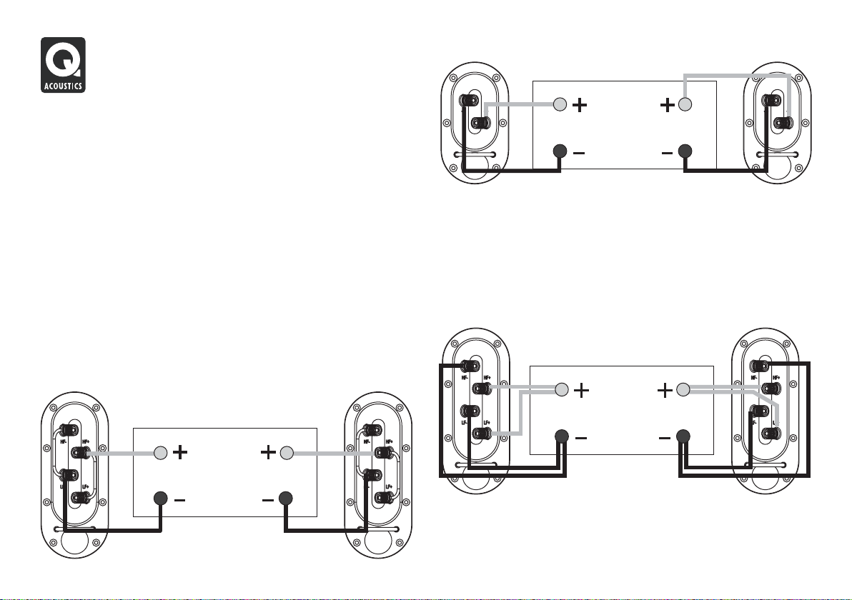
In the case of the 1020i, 1030i and 1050i you may use any convenient
Positive(+) or Negative (–) terminal. Refer to theillustrationbelow.
ii
Standard Wiring: 1020i, 1030i and 1050i
RIGHT
SPEAKER
AMPLIFIER
LEFT
SPEAKER
RIGHT
SPEAKER
RIGHT SPEAKER LEFT SPEAKER
AMPLIFIER
LEFT
SPEAKER
Bi-Wiring
Directly connecting the treble and bass networks of a loudspeaker to an
amplifier improves both bass performanceanddynamicrange.
To bi-wire: Prepare two twin cables for each loudspeaker. Unscrew all
the loudspeaker terminals and remove both links. Now connect the
treble terminals and the bass terminals to the amplifier following the
procedure described in Standard Wiring.Referto the illustration below.
Bi-Wiring: 1020i, 1030i and 1050i
RIGHT
SPEAKER
RIGHT SPEAKER LEFT SPEAKER
AMPLIFIER
LEFT
SPEAKER
When your speakers are connected: Switch on the system and play
some music at moderate level.Finetunethespeaker placement to suit.
RIGHT SPEAKER LEFT SPEAKER
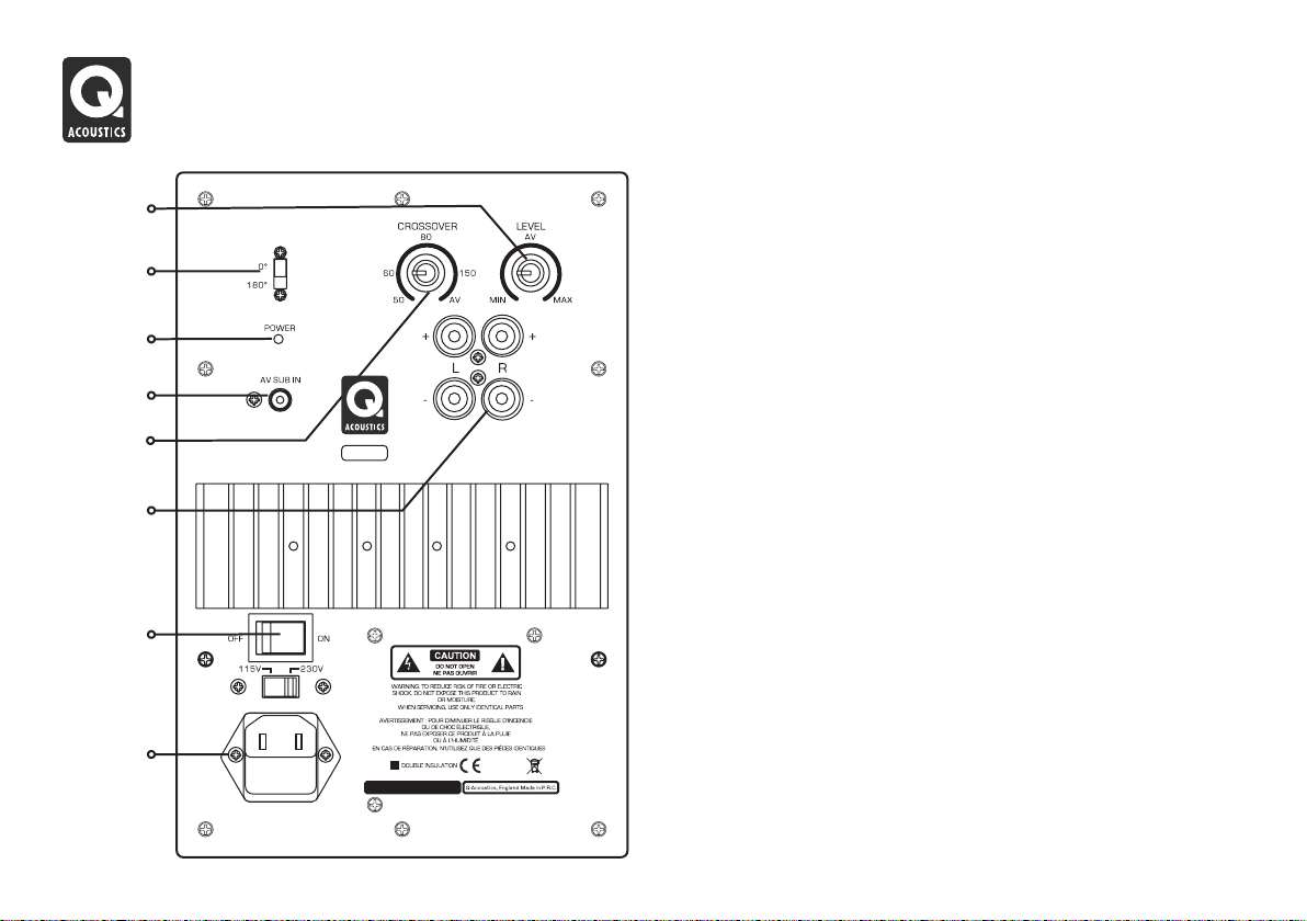
1000i Subwoofer
Level
Control
Phase
Switch
Power
Indicator
Line
Input
Crossover
Control
Speaker
Inputs
ON/OFF
Switch
Mains
Input
110V/120V-60Hz
Fuse Type: T 2AL/250V
220V/240V-50Hz
Fuse Type: T 1AL/250V
MAX 100 W ATTS
S
000 Powered Sub Woofer
i
1
Preliminaries
Unpack the subwoofer following theguidelinesgivenearlier.
The subwoofer is set to the voltage in your area. If you move to an area
with a different voltage, take the unit to a qualified technician to have the
voltage changed. This is somethingthatyoushouldnot do yourself.
Before connecting the subwoofer please make sure that all the active
units in your system areswitchedoffatthe mains.
Positioning the Subwoofer
Bass frequencies are substantially omnidirectional. Althoughthis means
that you can position the subwoofer almost anywhere, the stereo image
will still benefit by siting the subwoofer level with the front loudspeakers
and as central to the listening position as possible. This may not be
feasible in a multichannel system. If you place the subwoofer close to a
wall the bass will be re-inforced though in some locations the bass may
be boomy and indistinct. Donotplacethesubwoofer across a corner.
The subwoofer should be positioned close to a mains power source. Do
not use extension cables. Purchasealongerpower cord if necessary.
The MAINS ON/OFF switchisthe means of disconnecting this apparatus
from the mainsand is mounted onthe rear panel. There should be ample
free space between the rear of the cabinet and any wall or other object to
allow free unrestricted access tothisswitch.
When siting the subwoofer ensure the floor is sound with no loose
floorboards etc. The air movementfromthe subwoofer at high volumes is
substantial - do not place it close to soft furnishings or objects that may
rattle. Do not place objectsofanykindon the unit.
Connecting the 1000i Sub
Subwoofer Connections
Standard Connection via the AV SUB Input
You will need a single RCA phono interconnect. As this cable is likely to
be quite long, make sure you get a good quality fully screened cable.
Your Q Acoustics dealer will be happy to supply you with a suitable
interconnect.
AV AMPLIFIER
SUBWOOFER
LEFT
RIGHT
REAR LS FRONT LS
CENTRE LS
RIGHT
LEFT
SUB
OUT
RIGHT SPEAKER LEF T SPEAKER
Connect the SUBWOOFER OUTPUT on the amplifier to the AV SUB
INPUT on the subwoofer using a suitable RCA interconnect. Push the
plugs firmly home to ensureagoodcontact.
If you wish to connect the1000i Sub to a preamplifier or aspare line output
on a regular amplifier, do NOT use a Stereo to Mono ‘Y’ adaptor or your
sound system will be set into Mono! Your dealer will advise you about a
suitable adaptor. Alternatively,usethe High Level connection.
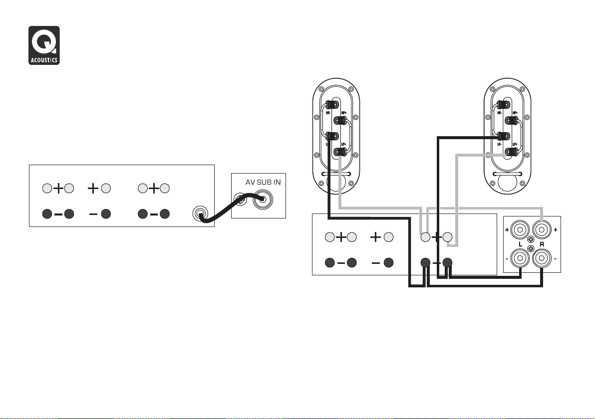
High Level Connections
In this mode the subwooferisconnectedto the amplifier together with the
Front loudspeakers. This connection should be used only if a dedicated
subwoofer line output is unavailable.
Never connect to both the high and line level inputs!
LEFT
RIGHT
REAR LS
AV AMPLIFIER
CENTRE LS
RIGHT
FRONT LS
LEFT
SUB.
Prepare two lengths of twin core loudspeaker cable. Unscrew the high
level terminals on the rear of the subwoofer. Connect the RED (+)
terminal on the RIGHT subwoofer input to the RED, Positive (+) terminal
on the RIGHT channel of the amplifier. Connect the BLACK (–) terminal
on this input to the matching BLACK, Negative (–) terminal on the
amplifier. Repeat this procedure for the LEFT channel. Leave the front
loudspeakers connected. The internal circuitry of the subwoofer will
combine the front channels toproduceasinglecommon bass channel.

1000i Subwoofer - Operation
Switching On
Check that all system connectionsareproperlyandsecurely made.
Ensure that the subwoofer isswitchedoff.
Set the subwooferlevel control roughly halfway. Set the crossover control
to 70Hz.
Plug the supplied power cord into thesubwoofer and then into the mains
point. Switch on the power at the mains point and then switch the
ON/OFF switch on the subwoofer to ON. The POWER light on the
subwoofer rear panel will glowand the subwoofer is operational.
Setting Up and Use
As there is a close relationship between the subwoofer volume, its
physical position and the crossover frequency, mutual adjustments to all
three may benecessarybeforethe system is fully set up.
Level: The Level Control sets the volume of the subwoofer relative to the
other speakers in the system. Set a level that enhances the bass of the
system. There should be a seamless blend between the front speakers
and the subwoofer.Ifyoucan hear the subwoofer it’s too loud!
Crossover frequency: Set the crossover control according to the size
and low frequency extension of the front speakers. The role of the
subwoofer is to extend the bass response of the system and not to
increase the overall bass level. If the loudspeakers are large, a value
between 50 and 60 Hz is probably about right. With smaller speakers
such as the 1010i,thiscan be increased as far as90Hz.At higher settings
the subwoofer may become intrusive and low level detail and definition
may suffer.
As always the final settings should be determined by listening. You
should listen to a wide range of music at different volume settings while
doing the setup.
When setting upthe subwoofer, always bear in mindthat the human ear’s
sensitivity to bass varies enormously with the volume level, hence the
need for a wide rangeofprogrammematerialand sound levels.
Phase: The phase switch should be initially set at 0º. As room acoustics
and placement are important at very low frequencies the phase may
need to be set to 180º. One setting will offer fuller and more extended
bass than the other. As the effect can be quite subtle, especially with
small loudspeakers where relatively more bass is coming from the
subwoofer, extended listening and experimentation may be necessary
before the final decision ismade.
Auto Power On: This feature enables you to switch the main system on
and off withouthavingto remember to switch thesubwoofer on and off as
well.
The 1000Si has a built inlevel sensor. If there isno input, after a short time
the subwoofer will automatically power down into Standby mode. This is
indicated by the POWER light on the rear panel changing to red. As soon
as the subwoofer senses an input it will automatically switch into
operational mode and the powerlightwillagainglow green.
Although the subwoofer can be safely be left in standby mode
indefinitely,if you are going to be absent from home for a long period, we
advise that the unit beswitchedoffatthe ON/OFF switch.
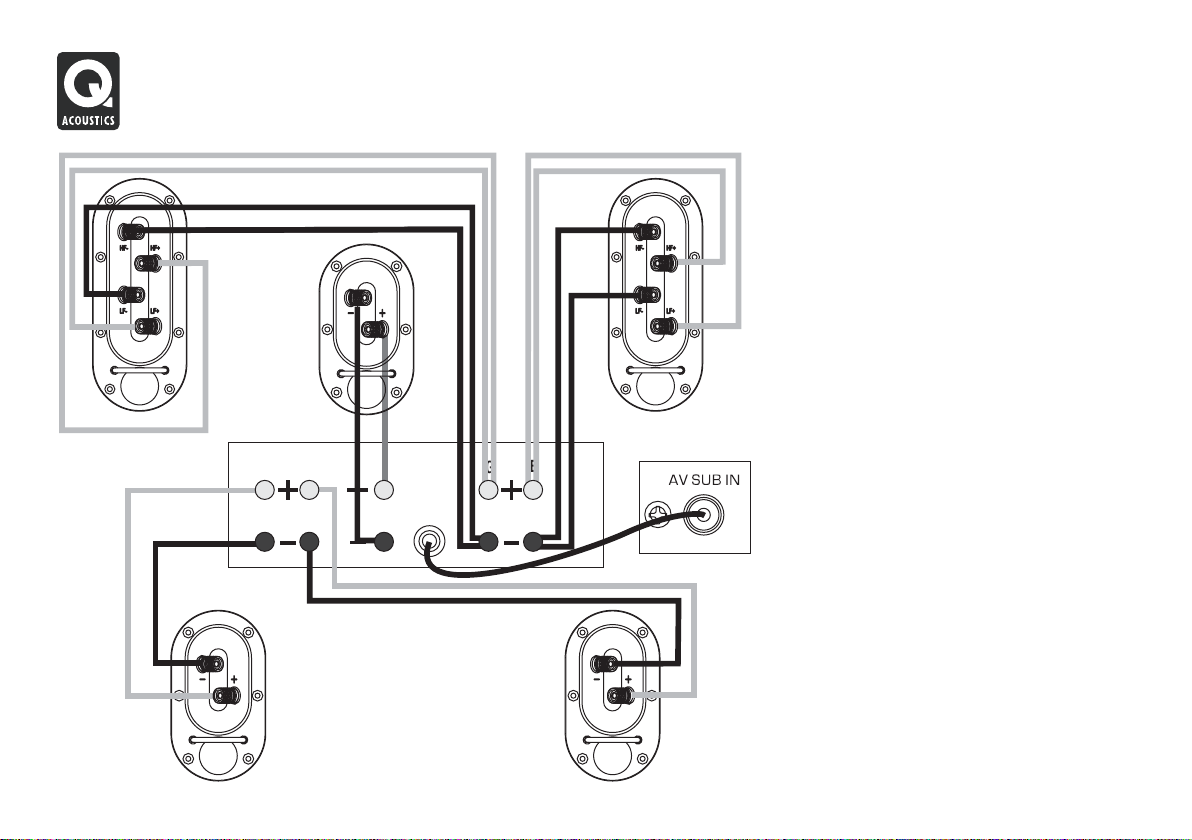
5.1 Home Theatre Connections
CENTRE
RIGHT FRONT
AV AMPLIFIER
LEFT
RIGHT
REAR LS
CENTRE
RIGHT
SUB
OUT
LEFT
FRONT LS
LEFT FRONT
SUBWOOFER
Home Theatre Connections
The Front Speakers are bi-wired. This is the
preferred mode of connection provided the
crossover network supports bi-wiring.
The Centre and Surround channel speakers
are conventionally wired.
6.1 and 7.1 connections are the same as 5.1
connections with the addition of the extra
effects channel/s.
When running loudspeaker cables be
especially careful not to run them across open
floor areas where they could be a source of
danger. Run loudspeaker cables around room
boundaries whenever possible.
Line level signal cables should be run apart
from mains cables. Never run line level signal
cables parallel to power cables especially on
long runs.
If the subwoofer is triggered on by appliances
switching on and off, re-route the input signal
cable before taking further measures.
RIGHT SURROUND
LEFT SURROUND
Home Theatre Topics
CENTRE
1
SUB
2
2
0
5
º
-
3
1
-
º
LEFT
0º
SURR
LEFT
BACK LEFT
Above is the Dolby Labs recommended layout for 7.1systems.
The 6.1 layout is the same except a single central speaker replaces
the two back units. The 5.1 layout has no back speakers
RIGHT
0
º
9
0
º
-
1
1
0
º
º
5
3
BACK RIGHT
SURR
RIGHT
Placement: The Front and Centre speakers should bein line. If this is not
possible, consult your processor manual for guidance on adjusting
relative centre/front delay times. If you have a 5.1 system, the listening
seat can be closer totherearwall.As always, be prepared to experiment.
Bass Management: AV processors offer the choice of ‘Large’ or ‘Small’
for the speakers. If you choose ‘Large’ the speaker receives the full
frequency. Choose ‘Small’ and the bass is sent to the Subwoofer. We
recommend you choose ’Small’ for the 1000Ci and the 1010i and 1020i
wherever theyare used in the system. The 1050i should be set to ‘Large’.
The 1030i would normally besetto‘Large’but you may set it to ‘Small’
The subwoofer option should beenabled(setto‘ON’ or ‘YES’)
Levels: When the basic system parameters have been established, put
your processor into the ‘setup’ routine.Set up each individualspeaker so
that the level is the same at the listening position as all the others. If your
processor enables you to adjust the delay times, follow the instructions
closely as this will profoundly affect the final result. When you play a
movie you may think the rear channels are too soft - they aren’t! You may
however have to adjust the subwoofer level both at the processor and at
the subwoofer. Once set, do notre-adjusttheselevels.
LFE: The LFE channel sends all the bass sound effects to the subwoofer.
If speakers are set to ‘Small’ , system bass from those channels is also
sent to the subwoofer. If you play the system at extreme levels and/or
have the subwoofer level set too high you may overdrive the subwoofer
with unpleasant sonic results. If this occurs, reduce the level
immediately.
Phase: If your speakers are incorrectly wired the bass will be blurred and
thin. In this case, check the wiring carefully. If your speaker wire has a
tracer along one core, consistently use the striped core toconnect all the
positive (RED) terminals. In thiswaythesystemwill always be in phase.
Always follow the instructions in your AV processor manual!

Care and Cleaning Warranty
Cabinet Care
Clean cabinets with a barely damp cloth. The finish is sealed with a high
quality sealant so that in normal use there is no need to use solvent
based cleaning materials. If the cabinets become stained, remove the
stain with a cloth lightly moistened with water, white spirit or isopropyl
alcohol depending on the stain. Then lightly buff with a cloth to remove
any residue of the cleaningagent.Neveruseabrasives of any kind.
Grilles
Lightly brush out grilles with a soft brush. Do not remove the speaker
grilles unless absolutely necessary.
Drive Units.
Drive units are best left untouched as they are easily damaged when
exposed.
Q Acousticsloudspeakers are warranted free of defects in materials and
workmanship as follows:
Passive Loudspeakers: 5 years from the dateofpurchase
Active Loudspeakers & Subwoofers: 2 years from the date of purchase
During the warranty period Q Acoustics will, at its option, repair or
replace any product found to be faulty after inspection by the company
or its appointed distributor oragent.
Misuse and fair wear andteararenotcovered by warranty.
Goods for repair should in the first instance be returned to the supplying
dealer. If this is not possible the item/s should be sent carriage paid
preferably in the original packing, to Q Acoustics or their appointed
distributor for your area and accompanied by proof of purchase.
Damage sustained by goods in transit to the repair centre is not covered
by warranty. Return carriage will be paid by Q Acoustics or their
distributor as appropriate.
This warranty does not inanywayaffectyour legal rights.
Appointed Distributor in the UK:
Armour Home Electronics Ltd
Units 7 & 8, StortfordHallIndustrialPark
Bishops Stortford, Herts, UK
CM23 5GZ
For service information In other countries contact
info@qacoustics.co.uk

Q Acoustics 1000i Series Specifications
Passive Loudspeakers
Enclosure type:
Bass Unit (mm):
Treble Unit (mm):
Frequency response: (±3dB):
Nominal Impedance:
Minimum Impedance:
Sensitivity (2.83v@1m):
Recommended amplifier power:
Crossover frequency:
Effective volume:
Cabinet dimensions (HxDxW mm):
Weight (per cabinet):
1000Si Active Subwoofer
Enclosure type:
Bass Unit (mm):
Amplifier power:
Crossover frequency:
Cabinet dimensions (HxDxW mm):
Weight :
1010i 1020i 1030i 1050i 1000Ci
2-way reflex
100 mm
25 mm
68Hz - 20 kHz
6Ù
4Ù
86dB
15 - 75W
2.5 kHz
3.4 litres
H215 x D195 x W150
2.8 Kg
Ported
200 mm long throw
100 Watts
45Hz - 175Hz (var.)
H330 x D350 x W320
11.0Kg
2-way reflex
125 mm
25 mm
65Hz - 20 kHz
6Ù
4Ù
88dB
25 - 75W
2.8 kHz
7.0 litres
H250 x D265x W175
4.0 Kg
2-way reflex
165 mm
25 mm
48Hz - 20 kHz
6Ù
3.6Ù
90dB
25 - 100W
2.7 kHz
17.7 litres
H900 x D295 x W195
15.5 Kg
2-way reflex
2 x 165 mm
25 mm
44Hz - 20 kHz
6Ù
3.8Ù
92dB
25 - 150W
2.4 kHz
35.7 litres
H975 x D295 x W195
17.8 Kg
2-way reflex
2 x 100mm
25 mm
75Hz - 20 kHz
6Ù
4.7Ù
89dB
25 - 100W
2.8 kHz
5.2 litres
H150 x D195 x W425
5.5 Kg


Serie 1000i
EN
FR
IT
ES
DE
EL
Mode d’emploi et
caractéristiques
techniques du produit
ZH
RU
Veuillez lire ces instructions.
Veuillez conserver ces instructions.
Veuillez prendre connaissance de tous les avertissements.
Veuillez suivre toutes les instructions.
N’utilisez pas cet appareil à proximité de l’eau.
Nettoyez uniquement avec un chiffon sec.
N’obstruez pas les grilles de ventilation.
Suivez attentivement les instructions du fabricant lors de l’installation.
N’installez pas cet appareil à proximité d’une source de chaleur telle que
des radiateurs, des bouches d’air chaud, des fours, ou tout autre appareil
(y compris des amplificateurs) produisant de la chaleur.
Ne supprimez pas la sécurité apportée par la prise polarisée ou de
type B. Une prise polarisée possède deux broches, dont une plus large
que l’autre. Une prise de type B possède deux broches et une fiche terre.
La broche la plus large ou la fiche terre sont là pour votre sécurité. Si la
prise fournie ne convient pas, adressez-vous à un électricien pour une
mise aux normes de votre installation électrique.
Evitez de marcher sur le cordon d’alimentation ou de le pincer, en
particulier, à l’extrémité du cordon, de la prise et à la sortie de l’appareil.
Utilisez uniquement des accessoires spécifiés par le fabricant.
Utilisez uniquement les chariots, pieds, tripodes,
supports ou les tables recommandés par le fabricant
ou vendus avec l’appareil.
Si vous utilisez un chariot, faites très attention lors du transport de
l’appareil et évitez de le faire tomber pour ne pas vous blesser.
Débranchez cet appareil en cas d’orage ou lorsque vous ne vous en
servez pas pendant une période prolongée.
Pour toute réparation, adressez-vous à un professionnel. Faites réparer
cet appareil pour des dommages de n’importe quelle nature : cordon
d’alimentation abîmé, liquide ou objet introduit dans l’appareil,
exposition à la pluie ou à l’humidité, fonctionnement inhabituel,
chutes diverses.
Avertissement : Afin de diminuer les risques d’incendie ou de choc
électrique, conservez cet appareil à l’abri de la pluie et de l’humidité.
Evitez toute éclaboussure et ne posez pas d’objets contenant des
liquides, comme des vases, sur cet appareil.
Tenir à l’écart des flammes et ne pas poser de bougie sur cet appareil.
Avertissement : L’interrupteur de mise en marche du subwoofer sert à
mettre cette unité hors tension. Cet interrupteur est situé sur le panneau
arrière. Afin de pouvoir accéder librement à cet interrupteur, l’appareil
doit être placé dans un endroit ouvert sans aucun obstacle. L’interrupteur
doit lui aussi être libre d’accès.
Attention : Tout changement, ou modification, non expressément
autorisé par le fabricant annule la garantie.
Réparation : Pour toute réparation, renvoyez l’appareil au fournisseur,
ou au réparateur de votre région; La liste des adresses des réparateurs
au RU figure dans ce manuel.
Tiers : Au cas improbable ou vous revendiez ce produit a un tiers,
veuillez fournir ce mode d’emploi avec le produit.
Remarque importante pour les
utilisateurs au Royaume-Uni
Le cordon d’alimentation possède une prise anglaise contenant un
fusible de 5A. Si le fusible doit être remplacé, utilisez un fusible de 5A
de type ASTA ou BSI à la norme BS1362. Si vous devez changer la prise
elle-même, ôtez le fusible avant de jeter la prise immédiatement après
avoir coupé le cordon d’alimentation.
Branchement sur secteur
Les couleurs des fils du cordon d’alimentation sont en conformité avec
le code suivant : Bleu : NEUTRE; Marron : PHASE.
Ces couleurs ne correspondant peut être pas à celles des fiches de votre
prise, procédez comme suit :
Connectez le fil BLEU
à la borne affichant la
lettre N ou de couleur
BLEUE ou NOIRE.
Connectez le fil
MARRON à la borne
affichant la lettre L ou
de couleur MARRON
ou ROUGE.
Ce symbole indique des instructions d’utilisation et d’entretien
essentielles dans la documentation qui accompagne cet appareil.
Ce symbole indique la présence dans cet appareil d’un voltage
dangereux, qui peut poser un risque de choc électrique.
362
Informations importantes – Lire attentivement
RISQUE DE CHOCS ELECTRIQUES
POUR DIMMINUER LE RISQUE DE CHOCS ELECTRIQUES NE PAS ENLEVER LE BOITIER
AUCUNE PIECE NE PEUT ETRE ENLEVEE PAR L’UTILISATEUR À L’INTERIEUR
CONSULTER UN PROFESSIONEL QUALIFIE POUR TOUTE REPARATION
ATTENTION!
NE PAS OUVRIR
(NI LE PANNEAU ARRIERE)
BS 1

Série Q Acoustics 1000i
Introduction
La gamme d’enceintes de série Q Acoustics 1000i est conçue pour
répondre aux besoins des cinéphiles et des amateurs de musique. Notre
gamme comprend :
1010i : Une enceinte d’étagère compacte avec un caisson de basses de
100 mm.
1020i : Une enceinte d’étagère avec un caisson de basses de 125 mm.
1030i : Une enceinte colonne avec un caisson de basses de 165 mm.
1050i : Une enceinte colonne avec deux caissons de basses de 165 mm
1000Ci : Une enceinte centrale avec deux caissons de basses de 100
mm, pouvant être fixée au mur, si nécessaire.
1000Si : Un subwoofer actif de 100 Watt avec un haut-parleur de 200 mm
et un détecteur de signal pour allumage/arrêt automatique.
Vous pouvez effectuer un bi-câblage sur toutes les enceintes passives sauf
la 1010i et la 1000Ci.
Toutes les enceintes fonctionnent à proximité des écrans de télévision sans
aucun problème à l’exception des enceintes de la gamme 1000Si, qui ne
doivent pas être placées à moins de 500 mm d’écrans de télévision ou de
tout autre matériel pouvant être perturbé par un champ magnétique. Cela
n’affecte pas les écrans à plasma ni les écrans à affichage à cristaux
liquides.
Avant de brancher vos enceintes, assurez-vous que toutes les parties
actives de votre système audio sont éteintes ou hors tension.
Lorsque vous allumez votre système audio ou lorsque vous changez les
sources d’entrée, baissez le volume jusqu’à un bas niveau. Montez
graduellement le son.
Ne montez JAMAIS le son au maximum. Le bouton de contrôle du volume
est trompeur et n’indique pas la puissance du système audio. L’utilisation
du volume au maximum peut endommager votre capacité auditive.
Ne raccordez PAS les bornes de votre enceinte au secteur.
Ne laissez PAS vos enceintes dans des endroits trop froids, trop chauds,
trop humides ou au soleil.
Si vous utilisez vos enceintes sans les grilles de protection, faites bien
attention à ne pas endommager les haut-parleurs.
N’utilisez PAS des pieds de fortune. Installez vos enceintes sur des pieds
recommandés par Q-Acoustics selon les instructions, en utilisant les
pointes de fixation fournies. Votre revendeur pourra vous conseiller.
NE démontez PAS vos enceintes car vous annuleriez la garantie.
Déballer vos enceintes
Déballez complètement vos enceintes. Sortez les enceintes du carton en
soulevant les enceintes elles-mêmes. Ne vous servez pas de sacs en
polyéthylène pour les soulever. Les enceintes 1030i, 1050i, et 1000Si sont
assez lourdes; demandez de l’aide pour les soulever, si nécessaire.
Lorsque vous déplacez les enceintes, ne les traînez pas par terre car vous
risquez de les endommager. Soulevez-les avant de les déplacer.
Vous trouverez dans le carton : Le(s) enceinte(s) et ce mode d’emploi.
Pour les modèles suivants, le carton d’emballage contient également :
1030i et 1050i : Un socle pour chaque enceinte, des vis, une clef
hexagonale pour fixer le pied et un paquet de pointes de fixation au sol et
de protège-pointes.
1010i, 1020i, 1000Ci : Un paquet de quatre pieds adhésifs.
1000Si : Un cordon d’alimentation C.E.I. adapté à votre pays.
Vérifiez bien le produit. Si l’un des articles est manquant ou endommagé,
contactez votre revendeur dès que possible.
Conservez l’emballage pour transporter le matériel ultérieurement. Si vous
décidez de jeter l’emballage, respectez la réglementation de votre pays en
matière de recyclage.
Installation
Installation du pied et des pointes – 1030i et 1050i
Placez un chiffon doux ou une
serviette au sol. Retournez l’enceinte
et placez-la sur le chiffon.
Le pied est constitué d’un socle et
d’une colonne. Fixez le socle sur la
colonne à l’aide des cinq vis
courtes. Utilisez la clef hexagonale
pour resserrer les vis correctement.
Retournez le pied et placez les
quatre boulons longs dans le
socle et la colonne. Alignez les
boulons dans les trous prévus en
dessous de l’enceinte et serrez
correctement.
Assurez-vous que le creux du pied
est tourné vers l’arrière de
l’enceinte.
Vissez à moitié les fixations sur le
socle et remettez l’enceinte à
l’endroit. (Si vous possédez un sol
en bois ou en pierre enfoncez les
protège-pointes sur chaque fixation
avant de remettre l’enceinte à
l’endroit).
Une fois l’enceinte à l’endroit,
resserrez chaque fixation avec la
clef hexagonale en partant du haut
et ajustez plus ou moins les
fixations jusqu’à ce que l’enceinte
soit à niveau et parfaitement stable.
Remplissage au sable du modèle 1030i
Vous pouvez remplir la partie basse du modèle 1030i de sable afin de le
stabiliser et de réduire les vibrations sonores. Cela dépend entièrement de
vous. Si vous ne le faites pas, cela ne l’endommagera pas.
Vous aurez besoin de:
• 5kg de sable sec; du sable
de jeu est idéal. N’utilisez pas
de sable de construction.
• Un grand sac solide en
polyéthylène.
• Un pichet sec.
Otez le bouchon du panneau
arrière. Enfoncez le sac dans
la partie basse de l’enceinte
avec l’ouverture du sac
dépassant d’au moins 100
mm. Versez soigneusement
(ou utilisez une cuiller) le sable
dans le sac. Lorsque le sac est
plein, refermez-le bien et
enfoncez le complètement
dans l’enceinte. Replacez le
bouchon.
1010i, 1020i, 1000Ci
Chaque enceinte est livrée
avec quatre pieds adhésifs. Si
vous décidez de ne pas fixer vos enceintes au mur, ôtez la partie protectrice
des pieds et appuyez sur chaque pied pour le mettre en place dans
chaque coin du panneau inférieur à 15 mm du bord.
Fixations au sol très pointues. Faites très attention !
Ne placez jamais une enceinte avec des pointes de fixation dans des
endroits pouvant être endommagés !
Soulevez toujours vos enceintes pour les déplacer; ne les tirez jamais !

Positionner les enceintes passives
1030i et 1050i
Les enceintes 1030i et 1050i doivent être positionnées à 200 mm minimum
du mur arrière et à 500 mm des murs latéraux. En plaçant vos enceintes
plus près du mur, vous augmenterez les graves, mais cela peut résonner et
manquer de précision et de qualité. Les enceintes doivent être bien
placées, tournées vers l’auditeur et situées de 2 m à 4 m de distance les
unes des autres. Tourner légèrement les enceintes vers l’intérieur améliore
la qualité stéréo mais réduit la source sonore.
Un support conçu spécialement pour fixer les enceintes Q Acoustics 1010i,
1020i et 1000Ci au mur, est en vente chez votre revendeur. Des pieds pour
les enceintes 1010i et 1020i sont également disponibles.
Soyez prêt à expérimenter afin de trouver le meilleur agencement possible,
adapté à votre goût, dans la pièce que vous avez choisie.
Enceintes à effets
1000Ci
Le modèle 1000Ci a été conçu pour être utilisé à proximité d’un écran de
télévision. Il doit être placé directement au-dessus ou au-dessous de
l’écran. Si vous possédez un téléviseur traditionnel, assurez-vous qu’il
puisse soutenir les enceintes et qu’il offre une surface égale. Dans le cas
contraire, placez le téléviseur dans un meuble télé et l’enceinte 1000Ci sur
une étagère solide directement en-dessous du téléviseur.
Si vous possédez un écran à plasma ou à affichage à cristaux liquide, fixez
l’enceinte 1000Ci au mur ou sur toute autre surface
adéquate directement au-dessus ou au-dessous
de l’écran.
Enceintes Surround
Il y a des recommandations de Dolby labs pour les
enceintes à effets 5.1.
Montez les enceintes surround de chaque côté de
l’auditeur, légèrement en retrait par rapport à la
position d’écoute. Les enceintes doivent être
tournées vers l’intérieur et montées sur les murs
latéraux ou bien, si la pièce est large, montées sur
des pieds hauts, le centre des enceintes se trouvant
au-dessus du niveau de l’oreille de l’auditeur.
Dolby et le symbole du double-D sont
des marques déposées de Dolby Laboratories.
1010i et 1020i
Les enceintes 1010i et 1020i doivent si possible être montées sur des pieds
Q-Acoustics ou fixées au mur. Si vous choisissez de les mettre sur des
pieds, l’unité des aigus doit être à la hauteur des oreilles de l’auditeur. Les
enceintes montées au mur peuvent être placées être un peu plus haut et
inclinées vers le bas. Les enceintes sur pieds doivent être traitées comme
des enceintes colonnes mais peuvent être placées un peu plus près du mur
arrière. Ces enceintes peuvent également être placées sur des étagères.
>200 mm
2 m - 4 m
>500 mm
0-30°
2 m - 4 m
400 mm

Brancher les enceintes passives
Borniers et Connecteurs
Les enceintes 1020i, 1030i et 1050i peuvent être installées avec un bicâblage. Le principe du bi-câblage requiert quatre bornes. Les deux bornes
supérieures sont reliées à l’enceinte des aigus (HF) et les deux bornes
inférieures sont reliées à/aux enceinte(s) des graves (LF). Ces bornes sont
livrées avec des liaisons amovibles servant à relier les bornes entre elles.
Cela vous permet de brancher les enceintes de manière traditionnelle avec
une paire de câbles ou en « bi-câblage » avec les double-borniers.
Les enceintes 1010i et 1000Ci ont des bornes standard.
Câble des enceintes
Des câbles d’enceintes spécialisés vous permettront d’atteindre une meilleure
qualité de reproduction des sons que les câbles multi-usages traditionnels,
comme les fils de sonnerie. Utilisez des câbles avec une quantité assez
importante de cuivre pour les enceintes centrales et avant. Les câbles fins
diminuent les graves et limitent la gamme dynamique. Les enceintes
surround (arrières) sont moins importantes.
Les câbles d’enceinte possèdent une rayure ou un tracé en leur centre. Ils
sont traditionnellement reliés aux bornes positives. Les câbles reliant
l’amplificateur aux enceintes avant doivent être de la même longueur. Ne
raccordez jamais deux câbles – utilisez la longueur entière.
Préparer les câbles
Dédoublez les câbles sur 40 mm.
Dénudez les fils de 10 mm et tournez les
fils pour tous les rassembler. Sectionnez le
câble en en laissant 7 mm à nu.
Branchement
Dévissez la borne dans le sens contraire
des aiguilles d’une montre pour faire
apparaître le trou de montage prévu à la
base de la borne.
Insérez la partie dénudée du câble dans le
trou. Resserrez complètement la borne à
la main. Assurez-vous qu'aucun fil ne
dépasse qui pourrait entrer en contact
avec les bornes adjacentes.
Les règles européennes de sécurité
interdisent l’utilisation de fiches de 4 mm.
1020i, 1030i, 1050i
Branchement
standard
Bi-câblage
1010i, 1000Ci
.
Resserrer
7 mm
30 mm
Desserrer

Brancher des enceintes passives
Raccordements stéréo
Raccordements standard
Chaque enceinte est livrée avec un range-câbles pour les guider et les
ranger correctement. Les modèles 1010i, 1020i, 1030i, 1050i et 1000Ci
possèdent un range-câbles en bas du panneau des bornes.
Faites passer le câble par le range-câble avant de brancher l’enceinte.
Reliez la borne ROUGE (+) de l’enceinte de DROITE à la borne ROUGE,
Positive (+) sur l’enceinte de DROITE de l’ampli. Reliez la borne NOIRE
(–) de l’enceinte à la borne Négative, NOIRE, (–) correspondante de
l’amplificateur.
Répétez cette opération pour l’enceinte de GAUCHE.
Pour les modèles 1020i, 1030i et 1050i vous pouvez utiliser les bornes
Positives (+) ou Négatives (–) à votre gré. Veuillez vous référer au schéma
ci-dessous.
Bi-câblage
Brancher directement les aigus et les graves d’une enceinte sur un
amplificateur améliore à la fois la qualité des graves et la gamme
dynamique.
Pour le bi-câblage : Préparez deux câbles doubles pour chaque enceinte.
Dévissez toutes les bornes des enceintes et ôtez les deux liaisons. Reliez
ensuite les bornes des aigus et des graves à l’amplificateur selon le
procédé de branchement standard préalablement décrit. Veuillez vous
référer au schéma ci-dessous.
Lorsque vos enceintes sont raccordées : Allumez le système et mettez
de la musique à un volume modéré. Ajustez l’emplacement des enceintes
à votre goût.
Brancher le modèle 1010i et 1000Ci
ii
Branchement standard : 1020i, 1030i et 1050i
ENCEINTE
DROITE
ENCEINTE DROITE ENCEINTE GAUCHE
AMPLIFICATEUR
ENCEINTE
GAUCHE
ENCEINTE
DROITE
ENCEINTE DROITE ENCEINTE GAUCHE
AMPLIFICATEUR
ENCEINTE
GAUCHE
Bi-câblage : 1020i, 1030i et 1050i
ENCEINTE
DROITE
AMPLIFICATEUR
ENCEINTE DROITE ENCEINTE GAUCHE
ENCEINTE
GAUCHE

Subwoofer 1000i
Préparation
Déballez le subwoofer selon les instructions données préalablement.
Le subwoofer est adapté au voltage de votre pays. Si vous déménagez
dans un pays avec un voltage différent, consultez un professionnel qui
pourra changer le voltage de l’appareil. N’effectuez pas cette opération
vous-même.
Avant de brancher votre subwoofer, assurez-vous que toutes les autres
unités actives du système audio sont hors tension.
Positionner le Subwoofer
Les fréquences des basses sont principalement omnidirectionnelles.
Même si cela signifie que vous pouvez placer le subwoofer presque
n’importe où, l’image stéréo sera améliorée si vous alignez le subwoofer
avec les enceintes avant, bien en face de l’auditeur. Cela n’est peut être
pas possible avec un système à canaux multiples. Les graves seront
renforcées si vous placez le subwoofer près d’un mur mais à certains
endroits les graves résonneront et seront assez diffus. Ne placez pas le
subwoofer dans un coin.
Le subwoofer doit être placé à proximité d’une source d’alimentation.
N’utilisez pas de rallonges. Achetez un cordon d’alimentation plus long si
nécessaire.
L’interrupteur MARCHE/ARRET, situé sur le panneau arrière, permet de
mettre cet appareil hors tension. Il doit y avoir assez de place à l’arrière de
l’appareil pour pouvoir accéder à l’interrupteur librement, sans aucun
problème.
Lors du positionnement de votre subwoofer assurez-vous que le sol est
stable sans aucune planche de parquet flottante etc. Le déplacement d’air
est important lorsque le volume du subwoofer est monté assez haut; ne le
placez pas à proximité de pièces de mobilier garnies de tissus et
susceptibles de vibrer. Ne posez aucun objet sur cet appareil.
Contrôle
du niveau
Potentiomètre
Témoin de
mise sous
tension
Entrée
combinée
Répartiteur
Entrées
enceintes
Interrupteur
MARCHE/
ARRET
Entrée
d’alimentation
110V/120V-60Hz
Fuse Type: T 2AL/ 2 50 V
220V/240V-50Hz
Fuse Type: T 1AL/ 250V
MAX 10 0 WATTS
S
00 0 Powered Sub Woofer
i
1

Brancher le Sub 1000i
Raccordements Subwoofer
Branchement standard sur entrée AV SUB
Vous aurez besoin d’un câble audio standard RCA. Ce câble étant
généralement assez long, prenez du câble blindé de bonne qualité. Votre
revendeur Q Acoustics sera heureux de vous fournir le câble adéquat.
Préparez deux longueurs de câble d’enceinte dédoublé. Dévissez les
bornes de haut niveau à l’arrière du subwoofer. Reliez la borne ROUGE (+)
de l’entrée subwoofer DROIT à la borne Positive, ROUGE, (+) du canal
DROIT de l’amplificateur. Reliez la borne NOIRE (–) de cette entrée à la
borne Négative correspondante NOIRE, (–) de l’amplificateur. Répétez
cette opération pour le canal de GAUCHE. Laissez l’enceinte avant
branchée. Les circuits internes du subwoofer regrouperont les canaux
avant pour produire un seul canal de basses.
A l’aide d’un câble RCA adapté, reliez la SORTIE SUBWOOFER de
l’amplificateur à l’ENTRÉE AV SUB du subwoofer. Enfoncez bien les prises
pour garantir le contact.
Si vous souhaitez relier le Sub 1000i à un préamplificateur ou à une sortie
combinée sur un amplificateur traditionnel, N’utilisez PAS d’adaptateur en
T stéréo à mono, ou votre son sortira en Mono! Votre revendeur pourra là
aussi vous conseiller en matière d’adaptateur. Vous pourrez alternativement
utiliser un raccordement de haut niveau.
Raccordements de haut niveau
Dans ce mode, le subwoofer est relié à la fois à l’amplificateur et aux
enceintes avant. Ce branchement est utilisé uniquement lorsque la sortie
combinée du subwoofer n’est pas disponible.
Ne jamais relier à la fois à l’entrée combinée et à l’entrée de haut
niveau !
AV AMPLIFICATEUR
SUBWOOFER
DROITE
GAUCHE
ENCEINTE ARR ENCEINTE AV
ENCEINTE CENTRALE
DROITE
GAUCHE
SUB
OUT
AV SUB IN
ENCEINTE
DROITE
ENCEINTE
GAUCHE
DROITE
GAUCHE
ENCEINTE ARR
AMPLIFICATEUR AV
ENCEINTE CENTRALE
DROITE
GAUCHE
ENCEINTE AVANT
G
D
SUB.

1000i Subwoofer - Utilisation
Mise sous tension
Vérifiez que tous les raccordements du système sont bien en place.
Assurez-vous que le subwoofer est éteint.
Tournez de moitié le contrôle du niveau du subwoofer. Tournez le bouton du
répartiteur sur 70 Hz.
Enfoncez le cordon d’alimentation dans le subwoofer et branchez-le.
Appuyez sur le bouton MARCHE/ARRET du subwoofer pour l’allumer. Le
témoin de MISE SOUS TENSION du panneau arrière du subwoofer
s’allumera, indiquant que le subwoofer est opérationnel.
Démarrage et utilisation
Il existe une relation évidente entre le volume subwoofer, sa position et la
fréquence du répartiteur; vous devez donc ajuster ces trois paramètres
pour mettre en place votre système.
Niveau : Ce bouton contrôle le volume du subwoofer par rapport aux
autres enceintes du système. Sélectionnez un niveau qui améliorera les
graves dans le système. Les sons produits par les enceintes avant et le
subwoofer doivent se confondre. Si vous pouvez distinguer le subwoofer,
cela veut dire qu’il est réglé trop fort !
Fréquence du répartiteur : Réglez le contrôle du répartiteur selon la
taille et le câble des basses fréquences des enceintes avant. Le rôle du
subwoofer est de rallonger la réponse des basses du système et non
d’augmenter le niveau général des basses. Si les enceintes sont de grande
taille, réglez-le entre 50 et 60 Hz. Pour des enceintes plus petites comme le
modèle 1010i, vous pouvez monter jusqu’à 90 Hz. Un réglage trop élevé
fait que le subwoofer devient trop envahissant et vous perdez en détail
et définition.
Comme toujours les réglages se font à l’oreille. Vous devez écouter une
vaste gamme de musiques à des volumes différents pour effectuer les
réglages.
Souvenez-vous, lors de l’installation du subwoofer, que la sensibilité de
l’oreille humaine varie énormément selon le volume, d’où le besoin d’une
vaste de gamme de musiques et de niveaux sonores différents.
Phase : Réglez d’abord le potentiomètre sur 0°. L’acoustique de la pièce
et le positionnement des enceintes étant des facteurs importants à de très
basses fréquences, réglez le potentiomètre sur 180°. Le réglage du
potentiomètre permettra d’obtenir des basses plus riches et plus variées.
L’effet étant assez subtil, surtout sur de petites enceintes ayant plus de
basses sortant du subwoofer, vous devrez passer du temps à écouter et à
expérimenter avant de prendre une décision définitive.
Auto Power On : Cette commande vous permet d’allumer et d’éteindre le
système principal sans avoir à allumer ou à éteindre le subwoofer.
Le modèle 1000Si possède un détecteur de niveau intégré. S’il n’y a aucun
signal audio pendant une certaine durée, le subwoofer se met
automatiquement en veille. Vous remarquerez alors que le TEMOIN du
panneau arrière passe au rouge. Dès que le subwoofer détecte un signal,
il se met automatiquement en marche et le témoin indique le vert.
Bien que le subwoofer puisse rester en veille indéfiniment, si vous décidez
de vous absenter pendant de longues périodes, nous vous conseillons
d’éteindre cet appareil avec l’interrupteur de MARCHE/ARRET.

5.1 Raccordements du Home Theatre
Raccordements du Home Theatre
Sur les enceintes avant est préférable d’effectuer
un bi-câblage à condition que le réseau du
répartiteur le permette.
Les enceintes du canal central et Surround sont
branchées de manière conventionnelle.
Les raccordements pour un 6.1 et 7.1 sont les
mêmes que les raccordements pour un 5.1 mais
avec des canaux d’effets en plus.
Lorsque vous installez des câbles d’enceintes
faites très attention à ne pas les faire passer dans
des endroits dégagés au milieu de la pièce ou à
tout autre endroit où ils pourraient représenter un
danger. Faites passer les câbles d’enceinte le long
des murs si possible.
Les câbles de la sortie « Line level » doivent être
séparés des cordons d’alimentation. Ne faites
jamais passer des câbles de la sortie « Line level »
parallèlement aux câbles d’alimentation, en
particulier sur des longueurs importantes.
Si le subwoofer se déclenche lorsque vous allumez
ou éteignez des appareils électriques, modifiez
l’emplacement du câble du signal d’arrivée avant
d’entreprendre quoi que ce soit d’autre.
CENTRE
DROITE AVANT
AMPLIFICATEUR AV
DROITE
GAUCHE
ENCEINTE ARR
CENTRE
SORTIE
SUB
DROITE
GAUCHE
ENCEINTE AVANT
GAUCHE AVANT
SUBWOOFER
ENTREE AV SUB
SURROUND DROIT SURROUND GAUCHE

A propos du Home Theatre
Le schéma ci-dessus représente la disposition recommandée par Dolby
Labs pour les systèmes 7.1. La disposition du 6.1 est la même sauf que
la seule enceinte centrale remplaçe les deux enceintes arrière. Le
positionnement du 5.1 ne comporte pas d’enceintes arrière.
Positionnement : Les enceintes avant et centrales doivent être mises au
même niveau. Si cela n’est pas possible, consultez le manuel du processeur
qui vous permettra d’ajuster les temps de retard entre les enceintes centrales
et avant. Si vous possédez un système 5.1, la position de l’auditeur peut
être plus proche du mur arrière. Là encore, soyez prêt à faire des tests.
Gérer les graves : Les processeurs AV vous offre un choix en matière de
puissance. Si vous choisissez « Large » l’enceinte reçoit la fréquence
complète. Si vous choisissez « Small », le Subwoofer reçoit les graves. Nous
vous conseillons d’opter pour « Small » pour les modèles 1000Ci, 1010i et
1020i lorsque vous les utilisez dans votre système audio. Choisissez l’option
« Large » pour la 1050i. En ce qui concerne le modèle 1030i « Large » est
préférable mais vous pouvez également sélectionner « Small ». L’option
subwoofer doit être sélectionnée (sur « MARCHE » ou « OUI »)
Niveaux : Après avoir établi les paramètres de base de votre système,
mettez votre processeur sur « setup ». Tous les haut-parleurs doivent être
réglés de façon à obtenir le même niveau du point de vue de l’auditeur. Si
votre processeur vous permet de régler les temps de retard, suivez
attentivement les instructions car cela détermine les résultats obtenus.
Lorsque vous regardez un film, les canaux arrières peuvent sembler
atténués mais ils ne le sont pas! Vous pourrez cependant ajuster le volume
du subwoofer à la fois au niveau du processeur et du subwoofer. Une fois
ces réglages effectués, ne les réajustez pas.
LFE : Le canal LFE envoie tous les effets sonores des graves au subwoofer.
Si les enceintes sont sur « Small », les graves de ces canaux sont
également retransmis au subwoofer. Si vous utilisez votre système à des
niveaux extrêmement élevés et que vous avez réglé le niveau du subwoofer
trop haut, vous risquez de surcharger le subwoofer et d’obtenir des sons
assez déplaisants. Si cela se produit, baissez le niveau immédiatement.
Phase : Si vos enceintes sont mal connectées, les graves seront presque
inaudibles et de très mauvaise qualité. Dans ce cas, vérifiez les
raccordements. Si le câble de votre enceinte possède une rayure, utilisez
toujours le fil à rayure pour raccorder toutes les bornes positives (ROUGE).
Le système sera ainsi toujours correctement raccordé.
Suivez toujours les instructions du manuel du processeur AV !
CENTRE
2
1
SUB
2
0
5
º
-
3
1
-
º
GAUCHE
0º
SURR
GAUCHE
ARR GAUCHE
DROITE
0
º
9
0
º
-
1
1
0
º
º
5
3
ARR DROIT
SURR
DROITE

Entretien et nettoyage Garantie
Enceintes
Nettoyez le dessus des enceintes avec un chiffon légèrement humide. La
finition des enceintes est effectuée avec un vernis de haute qualité. Vous
n’avez donc pas besoin d’utiliser des produits ménagers à base de
solvants. Si les enceintes sont tachées, nettoyez la tache à l’aide d’un
chiffon légèrement humide, du white spirit ou de l’alcool isopropylique
selon la tache. Faites briller avec un chiffon afin d’éliminer toute trace de
produit d’entretien. N’utilisez jamais de produits abrasifs.
Grilles
Epoussetez les grilles avec une brosse douce. Ne démontez jamais les
grilles des enceintes à moins que cela ne soit absolument nécessaire.
Unités d’entraînement
Ne manipulez ou ne touchez jamais les unités d’entraînement des hautparleurs car elles sont facilement endommagées.
Les enceintes Q Acoustics sont garanties sans aucun défaut de fabrication
ou de vice de matière :
Enceintes passives : 5 ans après l’achat.
Enceintes actives & Subwoofers : 2 ans après l’achat.
Si un produit s’avère défectueux durant la période de garantie, Q Acoustics
s’engage à réparer ou à remplacer tout produit défectueux après
inspection par un revendeur ou un représentant de la compagnie.
Les mauvaises utilisations et l’usure habituelle ne sont pas couvertes par
la garantie.
Les produit défectueux doivent d’abord être renvoyés au revendeur. Si
cela n’est pas possible l’article doit être renvoyé de préférence dans son
emballage d’origine, frais de port payés, à Q Acoustics ou à leur
distributeur du pays, accompagné d’une preuve d’achat. Les dommages
causés lors du transport au centre de réparation ne sont pas couverts par
la garantie. Les frais de renvois seront pris en charge par Q Acoustics ou
par leur distributeur.
Cette garantie n’affecte en rien vos droits d’utilisateurs.
Revendeur autorisé au Royaume-Uni :
Armour Home Electronics Ltd
Units 7 & 8, Stortford Hall Industrial Park
Bishops Stortford, Hertfordshire
Royaume-Uni CM23 5GZ
Pour plus d’informations sur les réparateurs dans d’autres pays
veuillez nous contacter par e-mail à info@qacoustics.co.uk

Spécifications de la série Q Acoustics 1000i
Type d’enceinte :
Unité des basses : (mm)
Unité des aigus : (mm)
Réponse en fréquence : (±3dB)
Impédance Nominale :
Impédance Minimum :
Sensibilité : (2.83v@1m)
Puissance conseillée de
l’amplificateur :
Fréquence du répartiteur :
Volume effectif :
Dimensions : (HxPxL mm)
Poids : (par enceinte)
reflex 2 voies
100 mm
25 mm
68Hz -20 kHz
6 Ω
4 Ω
86dB
15 -75W
2,5 kHz
3,4 litres
H215xP195xL150
2,8 Kg.
Boîtier :
Unité des basses : (mm)
Puissance de l’amplificateur :
Fréquence du répartiteur :
Dimensions : (HxPxL mm)
Poids :
évent
200 mm grande portée
100 Watts
45Hz -175Hz (var.)
H330xP350xL320
11,0 Kg
reflex 2 voies
125 mm
25 mm
65Hz -20 kHz
6 Ω
4 Ω
88dB
25 -75W
2,8 kHz
7,0 litres
H250xP265xL175
4,0 Kg.
reflex 2 voies
165 mm
25 mm
48Hz -20 kHz
6 Ω
3,6 Ω
90dB
25 -100W
2,7 kHz
17,7 litres
H900xP295xL195
15,5 Kg.
reflex 2 voies
2 x 165 mm
25 mm
44Hz -20 kHz
6 Ω
3,8 Ω
92dB
25 -150W
2,4 kHz
35,7 litres
H975xP295xL195
17,8 Kg.
reflex 2 voies
2 x 100 mm
25 mm
75Hz -20 kHz
6 Ω
4,7 Ω
89dB
25 -100W
2,8 kHz
5,2 litres
H150xP195xL425
5,5 Kg.
Enceintes passives
Subwoofer actif 1000Si
1010i 1020i 1030i 1050i 1000Ci

Serie 1000i
EN
FR
IT
ES
DE
EL
Istruzioni d’uso per l’utente
e caratteristiche del prodotto
ZH
RU

Leggere le istruzioni.
Conservare le istruzioni per un uso futuro.
Rispettare tutte le avvertenze inerenti ai rischi.
Seguire tutte le istruzioni.
Non utilizzare quest’apparecchio in prossimità di acqua.
Pulire esclusivamente con un panno asciutto.
Non ostruire nessuna apertura per la ventilazione.
Installare conformemente alle istruzioni del fabbricante.
Non installare in prossimità di fonti di calore come radiatori, valvole di
regolazione termica, fornelli o altre apparecchiature (inclusi gli
amplificatori)che producono calore.
Non inficiare l’efficacia antinfortunistica della spina di tipo polarizzato o
con presa di terra. Una spina polarizzata dispone di una coppia di lame,
una più larga dell’altra. Una spina con presa di terra dispone di una coppia
di lame e di un terzo polo di messa a terra. La lama più ampia o il terzo
polo sono in dotazione per l’incolumità dell’utente. Qualora la spina in
dotazione non si adatti alla propria presa di corrente, consultare un
elettricista che provveda alla sostituzione della presa obsoleta.
Proteggere il cavo elettrico da calpestamenti vari o sollecitazioni moleste,
in particolare in spine, prese, innesti femmina e prese per apparecchi di uso
domestico, nonché nel rispettivo punto d’uscita dall’apparecchio.
Utilizzare unicamente gli accessori in dotazione specificamente indicati
dal fabbricante.
Utilizzare soltanto con un carrello, uno scaffale, un
cavalletto, una staffa o un tavolo specificamente
indicati dal fabbricante o venduti insieme
all’apparecchio.
In caso di utilizzo di carrello, prestare attenzione allo spostamento del
combinato dell’apparecchio, onde evitare danni provocati da un ribaltamento.
In caso di fulmini o di mancato utilizzo dell’apparecchio per lunghi periodi,
staccare la spina.
Per qualunque operazione di manutenzione rivolgersi a personale
specializzato. La manutenzione è richiesta nel caso in cui l’apparecchio sia
stato danneggiato in qualunque modo, come a causa di un danno riportato
dal cavo di alimentazione o dalla spina; in caso di spargimento di liquido
o di caduta di oggetti all’interno dell’apparecchio; in caso di esposizione
dell’apparecchio a pioggia o ad umidità, in caso di malfunzionamento o di
caduta dell’apparecchio stesso.
Attenzione: onde ridurre il rischio d’incendio o di scossa elettrica, non
esporre il prodotto a pioggia o umidità. Il prodotto non deve essere esposto
a gocce e spruzzi e sopra il prodotto non deve essere collocato nessun
oggetto contenente liquidi, come vasi di fiori.
Non collocare sopra il prodotto nessuna fonte di fiamma non protetta,
come candele.
Avvertenza: L’interruttore d’accensione della rete per il subwoofer è il
dispositivo impiegato per scollegare l’unità dall’alimentazione principale.
Questo interruttore si trova nel pannello posteriore. Per consentire la facile
accessibilità all’interruttore, l’apparecchio deve essere collocato in uno
spazio aperto che non presenti ostruzioni, e l’interruttore deve essere in
grado di funzionare liberamente.
Attenzione: cambiamenti o modifiche non espressamente approvate dal
fabbricante potrebbero invalidare l’autorizzazione dell’utente ad azionare
questo dispositivo.
Manutenzione: l’apparecchiatura per la manutenzione deve essere resa al
rivenditore presso cui è stato acquistato l’apparecchio o al rappresentante
di zona responsabile della manutenzione. Gli indirizzi dei principali
rappresentanti addetti alla manutenzione per tutta l’area britannica sono
elencati in questo manuale.
Terzi: nell’improbabile eventualità che questo prodotto venga ceduto a terzi,
accludere al prodotto le presenti istruzioni sul relativo funzionamento.
Avviso importante agli utenti
britannici
All’estremità del filo accessorio è collocata una spina approvata nel Regno
Unito, dotata di un fusibile 5A. Qualora sia necessaria la sostituzione del
fusibile, deve essere usato un fusibile conforme alle norme ASTA o BSI
approvato BS1362 con una corrente di 5A. Qualora fosse necessario
sostituire la spina, rimuovere il fusibile e smaltire la stessa, in modo sicuro,
subito dopo averla recisa dal filo.
Collegare una spina
I fili del conduttore isolato di rete presentano un colore che si accorda con
il relativo codice: Blu: NEUTRO; Marrone: ATTIVO: poiché questi colori
possono non corrispondere alle marcature colorate che identificano i
terminali della spina, procedere come segue:
il filo BLU deve essere
collegato al terminale
contrassegnato dalla
lettera N o di colore BLU
o NERO. Il filo MARRONE
deve essere collegato al
terminale contrassegnato
dalla lettera L o di colore
MARRONE o ROSSO.
Questo simbolo indica che l’incartamento corredato a quest’apparecchio
contiene istruzioni importanti sul funzionamento e la manutenzione.
Questo simbolo indica che all’interno della presente unità il voltaggio è
pericoloso e vi è quindi pericolo di una scossa elettrica.
362
Si prega di leggere attentamente quanto segue – contiene informazioni importanti
ATTENZIONE!
RISCHIO DI SCOSSA ELETTRICA
PER RIDURRE IL RISCHIO DI UNA SCOSSA ELETTRICA NON RIMUOVERE LA COPERTURA
L’INTERNO NON CONTIENE PARTI RIMUOVIBILI DA PARTE DELL’UTENTE
PER LA MANUTENZIONE, RIVOLGERSI A PERSONALE QUALIFICATO
NON APRIRE
(O LA PARTE POSTERIORE)
BS 1

Serie Q Acoustics 1000i
Introduzione
La serie Q Acoustics 1000i è una gamma d’altoparlanti concepita per
soddisfare le più alte aspettative degli appassionati di elettroacustica ad
alta fedeltà, fedeli ai 2 canali, e dei cinefili esigenti. La gamma include:
1010i: Altoparlante compatto provvisto di ripiano libri con bass driver da
100 mm.
1020i: Altoparlante con ripiano libri con bass driver da 125 mm.
1030i: supporto compatto da pavimento con un bass driver di 165 mm
1050i: supporto da pavimento con due bass driver da 165 mm
1000Ci: canale centrale con due bass driver da 100 mm, montato a muro
se necessario.
1000Si: Il subwoofer attivo da 100 Watt con un eccitatore di 200 mm e
rilevamento di segnale per accensione e spegnimento automatici.
Tutti gli altoparlanti passivi sono in bi-wiring salvo quelli 1010i e 1000Ci.
Tutti gli altoparlanti si possono mettere in funzione vicino ai monitor televisivi
senza effetti indesiderati tranne nel caso del 1000Si, che non deve essere
azionato entro il raggio di 500mm da schermi televisivi, monitor o altre
attrezzature magnetosensibili. Nessun effetto sugli schermi al plasma e a
cristalli liquidi.
Prima di procedere con qualunque collegamento agli altoparlanti
assicurasi che tutti gli apparecchi sotto tensione del sistema siano spenti
alla rete.
In fase di accensione del sistema acustico o di modifica delle fonti di
ingresso, impostare il regolatore di volume principale su un livello basso.
Alzare poi il livello gradualmente.
NON AZIONARE MAI il sistema acustico a tutto volume. La posizione del
regolatore di volume inganna e non segnala il livello effettivo di potenza del
sistema. Impostare il volume su toni molto alti può arrecare danni all’udito.
NON collegare i morsetti dell’altoparlante alla presa di rete.
NON esporre gli altoparlanti a freddo, caldo, umidità o luce solare
eccessivi.
Qualora si azionino gli altoparlanti sprovvisti di schermature, prestare
attenzione a preservare dai danni le unità del drive.
NON UTILIZZARE scaffali di ripiego. Sistemare lo scaffale approvato dalla
Q-Acoustics seguendo le istruzioni e utilizzando qualunque fissaggio in
dotazione. Il vostro rivenditore sarà in grado di consigliarvi.
NON smontare l’altoparlante per non invalidare la garanzia.
Disimballaggio degli altoparlanti
Disimballare tutte le componenti degli altoparlanti. Sollevare gli altoparlanti
dalle scatole reggendo gli armadietti. Non utilizzare i sacchi di politene per
sollevarli. Il 1030i, 1050i, e 1000Si sono pesanti, se necessario, chiedere
aiuto per sollevarli. Nel maneggiare gli altoparlanti non trascinarli sul
pavimento per non procurare danni – sollevarli prima di spostarli.
La confezione contiene: L’altoparlante/i e il manuale del presente prodotto.
In aggiunta, la confezione per i seguenti modelli contiene:
1030i e 1050i: Un piedestallo per ogni altoparlante, delle viti, una chiave a
brugola per fissare lo scaffale e un set di chiodi per pavimento e coprichiodi.
1010i, 1020i, 1000Ci: Un set di quattro basi adesive.
1000Si: Un cavo elettrico CEI adatto alla presa di rete di zona.
Controllare attentamente il prodotto. In caso di parti danneggiate o mancanti,
rivolgersi il prima possibile al proprio rivenditore.
Conservare la confezione per il trasporto del prodotto in futuro. In caso di
smaltimento dell’imballaggio si prega di attenersi alle norme sul riciclaggio
in vigore nella propria area di residenza.

Preparazione
Preparare lo scaffale sul pavimento e i chiodi – 1030i e 1050i
Disporre un panno soffice o un
asciugamano sul pavimento.
Capovolgere l’altoparlante e collocarlo
sul panno.
Lo scaffale è costituito da una base e
da una colonna. Fissare la base alla
colonna utilizzando le cinque viti corte.
In dotazione c’è una chiave di brugola
per serrare opportunamente le viti.
Capovolgere lo scaffale e inserire i
quattro bulloni lunghi attraverso la
base e la colonna; allineare i bulloni
con i fori di montaggio posti sul fondo
del diffusore e serrare bene per fissarli.
Controllare che la parte incavata dello
scaffale sia rivolta verso la parte
posteriore dell’altoparlante.
Inserire i chiodi per metà nella base e
riportare l’altoparlante in posizione
verticale. (Se il proprio pavimento è in
legno o pietra inserire un dispositivo di
protezione su ciascun chiodo prima di
girare il diffusore per riportarlo in
posizione verticale).
Quando il diffusore si trova in perfetta
posizione verticale, inserire la chiave a
brugola in ogni chiodo, dalla parte
superiore, e regolare tutti i chiodi
interni ed esterni finché l’altoparlante
non sia in orizzontale e ben saldo.
Riempire di terra il 1030i
Si può riempire l’alloggiamento inferiore del 1030i con un po’ di terra per
aiutare la stabilità e smorzare la vibrazione acustica. Questa operazione è
del tutto opzionale e, se omessa, non reca alcun tipo di danno.
Cosa servirà:
• 5kg di terra a secco –
l’ideale è la terra da gioco.
Non utilizzare la terra in uso
nell’edilizia.
• un sacco ampio e robusto di
politene.
• un recipiente asciutto per
versare la sabbia.
Rimuovere il tappo posto nel
pannello posteriore. Spingere il
sacco dentro l’alloggiamento
lasciando che il beccuccio
sporga di almeno 100 mm.
Versare attentamente (o
inserire a dosi) la terra nel
sacco. Quanto questo sarà
colmo, legare il beccuccio in
maniera sicura e spingere il
sacco nell’alloggiamento.
Rimettere il tappo.
1010i, 1020i, 1000Ci
Ogni altoparlante è provvisto di quattro basi adesive. Se non si sta già
procedendo con il montaggio degli altoparlanti a muro, staccare lo strato
dietro ogni base e sistemare ogni base, esercitando pressione con la
mano, in ogni angolo del pannello inferiore a 15mm da ciascun bordo.
I chiodi sono appuntiti. Fare attenzione!
Non collocare mai un altoparlante con i chiodi laddove questo
possa arrecare danni!
Spostare sempre gli altoparlanti sollevandoli – mai trascinarli!

Posizionamento degli altoparlanti passivi
1030i e 1050i
Gli altoparlanti 1030i e 1050i vanno collocati almeno a 200mm di distanza
dalla parete posteriore e a 500mm di distanza dalle pareti laterali. Una
collocazione dei diffusori più ravvicinata alla parete aumenterà pure i toni
bassi ma potrebbe comportare un suono roboante e l’assenza della
precisione e del dettaglio. I diffusori devono trovarsi a 2m - 4m di distanza
l’uno dall’altro e l’ascoltatore, da seduto, deve trovarsi in posizione centrale
rispetto ad essi. La leggera rotazione dei diffusori verso il centro affinerà
pure l’immagine stereofonica ma può limitare la sorgente acustica.
diffusore può essere collocato ad una distanza più ravvicinata rispetto alla
parete posteriore. E’ possibile anche il montaggio dello scaffale.
Presso il proprio rivenditore di fiducia è disponibile come optional una staffa
studiata specificamente per montare a muro il Q Acoustics 1010i, 1020i e 1000Ci.
Sono inoltre disponibili i supporti da pavimento per i modelli 1010i e 1020i.
Prepararsi a fare più di una prova per trovare la miglior soluzione possibile
che si adatti ai propri gusti ed alla particolare sala d’ascolto privata.
Altoparlanti con effetti
1000Ci
Il 1000Ci è stato concepito per esser messo in funzione in prossimità di uno
schermo televisivo e in posizione centrale rispetto allo stesso. Si deve
collocare subito sopra o sotto lo schermo. Qualora si utilizzasse un
normale set televisivo, assicurarsi che la tv abbia la capacità di supportare
convenientemente l’altoparlante e che la superficie sommitale
dell’apparecchio televisivo sia piana. In caso contrario, si consideri
in alternativa la collocazione della Tv su un armadietto con il 1000Ci
posizionato su un ripiano fisso e posto subito sotto di essa.
Se si dispone di un monitor al plasma o a cristalli liquidi, montare il 1000Ci
a muro o su un’altra superficie, purché idonea allo
scopo, posta subito sopra o sotto lo schermo.
Diffusori surround
Alcune raccomandazioni dai laboratori Dolby sui diffusori
per effetti 5.1 si impongono alla vostra attenzione.
I diffusori surround non devono essere montati ad
uno dei due lati dell’ascoltatore ma leggermente
indietro rispetto alla posizione dello stesso. I diffusori
devono essere collocati verso l’interno o montati sulle
pareti laterali della stanza o, nel caso di una stanza
ampia, su scaffali alti il cui centro sia al di sopra del
livello delle orecchie di un ascoltatore seduto.
Il simbolo Dolby e il simbolo con la doppia D
sono i marchi di fabbrica dei laboratori Dolby.
1010i e 1020i
Il montaggio ideale del 1010i e del 1020i è sugli scaffali Q-Acoustics da terra
o a muro. Se ci si trova in fase di montaggio dello scaffale, una semplice
regola da seguire è questa: l’unità dei toni acuti deve trovarsi all’altezza
delle orecchie di un ascoltatore seduto. I diffusori montati a muro possono
essere montati di poco più in alto con la cassa rivolta verso l’esterno e
posizionata in modo da creare un angolo retto (verso il basso) in direzione
delle orecchie dell’ascoltatore. I diffusori montati sullo scaffale vanno trattati
alla stregua di quelli che si montano sul pavimento con la variante che il
>200mm
2m - 4m
>500mm
0-30°
2m - 4m
400mm

Collegare gli altoparlanti passivi
Morsetti e serrafili
I 1020i, 1030i e 1050i sono in bi-wiring. Il crossover in bi-wiring ha quattro
morsetti. La coppia superiore di morsetti si collega al diffusore sui toni acuti
(HF) e la coppia inferiore al diffusore/i dei toni bassi (LF). Poiché in
dotazione, i crossover sono sistemati con barre rimuovibili per connettere
le coppie di morsetti, il che consente di collegare l’altoparlante in maniera
tradizionale utilizzando un paio di cavi o in modalità bi-wiring con due paia.
Il 1010i e il 1000Ci hanno crossover standard a due morsetti.
Cavi altoparlante
I cavi specialistici dell’altoparlante offriranno uno standard più elevato di
riproduzione rispetto al generalmente valido filo ‘da campanello’ o ‘zip’.
Impiegare cavi ad elevato contenuto di rame per i canali anteriore e
centrale. I cavi sottili riducono i toni bassi e limitano la gamma dinamica. I
canali surround (posteriori) sono meno critici.
Il cavo dell’altoparlante è dotato di una striscia o di un tracciante a fianco
di un nucleo. Per convenzione questo è collegato ai morsetti positivi. I cavi
che collegano l’amplificatore agli altoparlanti anteriori devono avere
idealmente la stessa lunghezza. Non congiungere mai i cavi – utilizzare
tutte le lunghezze per intero.
Predisporre i cavi
Dividere il cavo fino a una profondità di
40mm circa. Togliere il rivestimento isolante
del filo fino a una profondità di 10mm e
torcere le estremità per raggruppare
qualunque filo vagante. Tagliare le estremità
del cavo lasciando esposti 7mm di filo
senza rivestimento isolante.
Collegare un morsetto
Svitare il morsetto in senso antiorario per
esporre il foro di montaggio posto sulla
base della colonna del morsetto.
Inserire l’estremità del cavo priva di
rivestimento isolante all’interno del foro.
Serrare nuovamente e completamente il
morsetto a mano. Assicurarsi che non vi
siano fili vaganti che potrebbero essere in
contatto con i morsetti contigui.
Nella UE l’uso di spine da 4mm per
altoparlante è contrario alle norme di
sicurezza.
1020i,1030i,1050i
Collegamento
Standard
Collegamento
Bi-Wiring
1010i, 1000Ci
.
Stringere
7mm
30mm
Allentare

Collegamenti stereo
Collegamenti standard
Ogni altoparlante è provvisto di un dispositivo guidacavo così da
consentire una sistemazione ordinata dei cavi. Nel 1010i, 1020i, 1030i e nel
1050i e 1000Ci la guida è collocata in fondo al pannello del morsetto del
crossover.
Infilare il cavo dal basso verso l’alto attraverso la guida prima di collegare
l’altoparlante.
Collegare il morsetto (+) ROSSO dell’altoparlante DESTRO al morsetto
(+) Positivo ROSSO sul canale DESTRO dell’amplificatore. Collegare
il morsetto (–) NERO dell’altoparlante al corrispondente morsetto
(–) Negativo NERO dell’amplificatore.
Ripetere la procedura per il canale SINISTRO.
Nel caso del 1020i, 1030i e 1050i è possibile utilizzare qualunque morsetto
Positivo (+) o Negativo adeguato. Si veda l’illustrazione in basso.
Bi-Wiring
L’attacco diretto dei toni acuti e delle reti dei bassi di un altoparlante ad un
amplificatore migliora sia l’esecuzione dei bassi che la gamma dinamica.
Per il bi-wiring: predisporre una coppia di cavi gemelli per ogni
altoparlante. Svitare tutti i morsetti dell’altoparlante e rimuovere entrambe le
barre. Collegare ora i morsetti degli acuti e i morsetti dei bassi
all’amplificatore seguendo la procedura descritta nel Cablaggio Standard.
Si veda l’illustrazione in basso.
Collegare gli altoparlanti passivi
Quando gli altoparlanti sono collegati: attivare il sistema ed iniziare la
riproduzione di musica ad un volume moderato. Sintonizzare il diffusore nel
miglior modo possibile.
Collegare il 1010i e 1000Ci
ii
Cablaggio Standard: 1020i, 1030i e 1050i
DIFFUSORE
DESTRO
AMPLIFICATORE
DIFFUSORE
SINISTRO
DIFFUSORE
DESTRO
DIFFUSORE DESTRO DIFFUSORE SINISTRO
AMPLIFICATORE
DIFFUSORE
SINISTRO
Bi-Wiring: 1020i, 1030i e 1050i
DIFFUSORE
DESTRO
DIFFUSORE DESTRO DIFFUSORE SINISTRO
AMPLIFICATORE
DIFFUSORE
SINISTRO
DIFFUSORE DESTRO DIFFUSORE SINISTRO

1000i Subwoofer
Preliminari
Disimballare il subwoofer seguendo le linee guida precedentemente fornite.
Il subwoofer è impostato secondo la tensione dell’area di appartenenza. Se
ci si sposta in un’area con diverso voltaggio, si consiglia di far modificare il
voltaggio dell’apparecchio da un tecnico qualificato Non eseguire
l’operazione autonomamente.
Prima di collegare il subwoofer si prega di assicurarsi che tutte le unità
sotto tensione del sistema vengano spente dalla rete generale.
Come collocare il subwoofer
Le frequenze dei bassi sono essenzialmente onnidirezionali. Sebbene ciò
implichi che il subwoofer possa essere collocato quasi ovunque,
l’immagine stereofonica trarrà ancora vantaggio dal posizionamento
orizzontale del subwoofer con gli altoparlanti anteriori e il più centrale
possibile rispetto alla posizione d’ascolto, sebbene ciò possa essere
difficilmente realizzabile in un sistema multicanali. Qualora il subwoofer
venga collocato in prossimità di una parete, i toni bassi acquisiranno
potenza anche se in alcune postazioni essi possano risultare cupi e
impercettibili. Non posizionare il subwoofer in un angolo.
Il subwoofer deve essere collocato in prossimità di una sorgente elettrica di
rete. Non utilizzare cavi prolunghe. Se necessario, acquistare un cavo
elettrico più lungo.
L’interruttore DI RETE ON/OFF è il mezzo con cui il presente apparecchio
viene scollegato dalla rete e montato sul pannello posteriore. Provvedere a
lasciare lo spazio necessario tra il retro dell’armadietto e qualunque parete
o altro oggetto, per consentire il libero accesso all’interruttore.
Nel posizionare il subwoofer assicurarsi che il pavimento sia stabile e che
non abbia pannelli mobili allentati ecc. Il flusso d’aria prodotto dal
subwoofer a volumi elevati è notevole – non collocarlo in prossimità di
tappeti e tendaggi o di oggetti che possano vibrare. Non collocare nessun
tipo di oggetto sull’apparecchio.
Controllo
del livello
Interruttore
di fase
Indicatore
elettrico
Input di
linea
Controllo
crossover
Entrate del
diffusore
Interruttore
ON/OFF
Input
della rete
110V/120V-60Hz
Fuse Type: T 2AL/ 2 50 V
220V/240V-50Hz
Fuse Type: T 1AL/ 250V
MAX 10 0 WATTS
S
00 0 Powered Sub Woofer
i
1

Collegare il 1000i Sub
Attacchi del subwoofer
Collegamento standard ad entrata AV SUB
Servirà una presa RCA. Dato che questo cavo è verosimilmente piuttosto
lungo, assicurarsi di avere un cavo completamente schermato di buona
qualità. Il vostro rivenditore di prodotti Q Acoustics sarà lieto di fornire una
presa adatta.
Collegare IL TERMINALE D’USCITA DEL SUBWOOFER posto
sull’amplificatore al TERMINALE D’ENTRATA DEL SUB AV posto sul
subwoofer, utilizzando una presa RCA adatta. Spingere saldamente le
spine al loro posto onde assicurare un corretto contatto.
Se si desidera collegare il 1000i Sub ad un preamplificatore o ad un
terminale d’uscita di una linea di riserva su un amplificatore normale, NON
utilizzare un adattatore ‘Y’ da Stereo a Mono o il sistema acustico sarà
impostato su Mono! Il rivenditore di fiducia consiglierà l’adattatore idoneo. In
alternativa, utilizzare il collegamento Livello Alto.
Collegamenti livello alto
In questa modalità il subwoofer è collegato all’amplificatore insieme agli
altoparlanti anteriori. Ricorrere a questo collegamento solo qualora non sia
disponibile un terminale d’uscita di linea specifico per il subwoofer.
Mai collegare ad entrambe le entrate del livello di linea e del livello alto!
Predisporre due lunghezze del cavo dell’altoparlante dal doppio nucleo.
Svitare i morsetti del livello alto posti posteriormente sul subwoofer.
Collegare il morsetto (+) ROSSO sul terminale d’ingresso del subwoofer
DESTRO al morsetto (+) Positivo ROSSO sul canale DESTRO
dell’amplificatore. Collegare il morsetto (–) NERO su questo terminale
d’ingresso al morsetto (–) Negativo NERO corrispondente posto
sull’amplificatore. Ripetere questa procedura per il canale SINISTRO.
Lasciare collegati gli altoparlanti anteriori. Lo schema elettrico interno del
subwoofer combinerà i canali anteriori per produrre un unico canale di
bassi comune.
AMPLIFICATORE AV
SUBWOOFER
DESTRO
SINISTRO
DIFF. POST. DX DIFF. ANT. SX
DIFF. CENTR. SX
DESTRO
SINISTRO
S U B
OUT
AV SUB IN
DIFFUSORE
DESTRO
DIFFUSORE
SINISTRO
SINISTRO
DESTRO
DIFF. POST. SX
AMPLIFICATORE AV
DIFF. CENTR. SX
DESTRO
DIFF. ANT. SX
SINISTRO
S
D
SUB.

1000i Subwoofer – Funzionamento
Accensione
Verificare la perfetta messa a punto e la sicurezza di tutti i collegamenti del
sistema.
Accertarsi che il subwoofer sia spento.
Impostare il controllo del livello del subwoofer all’incirca a metà. Impostare
il controllo del crossover sui 70Hz.
Collegare il cavo elettrico in dotazione nel subwoofer e successivamente
nel punto di rete. Attivare la corrente nel punto di rete e poi premere
l’interruttore ON/OFF posto sul subwoofer in posizione ON. La spia
LUMINOSA sul pannello posteriore del subwoofer si illuminerà: il subwoofer
è in funzione.
Messa a punto e utilizzo
Visto il rapporto stretto tra il volume del subwoofer, la sua posizione fisica e
la frequenza del crossover, può rendersi necessario regolare
reciprocamente tutti e tre i fattori prima di mettere interamente a punto il
sistema.
Livello: il controllo del livello imposta il volume del subwoofer corrispondente
agli altri diffusori del sistema. Impostare un livello che migliori i toni bassi
del sistema. L’emissione del suono dei diffusori anteriori e quella del
subwoofer deve essere bilanciata. Se è possibile distinguere il subwoofer
signigfica che è troppo alto!
Frequenza del crossover: impostare il controllo del crossover secondo le
dimensioni e l’estensione della bassa frequenza dei diffusori anteriori. Il
subwoofer ha il compito di estendere la risposta dei bassi del sistema e
non quello di aumentare il livello generale dei bassi. Se gli altoparlanti sono
di grandi dimensioni, il valore appropriato sarà circa dai 50 ai 60 Hertz. Con
diffusori ridotti come nel caso del 1010i, l’aumento può raggiungere i 90Hz.
Con impostazioni superiori, il subwoofer può divenire eccessivo e quindi
inaccettabile, con potenziali effetti negativi sulla definizione e sul dettaglio
del livello dei toni bassi.
Come sempre, le impostazioni finali devono essere stabilite tramite
l’ascolto. Durante la messa a punto è infatti necessario ascoltare un’ampia
gamma di musica con diverse impostazioni di volume.
Nel mettere a punto il subwoofer, ricordare sempre che la sensibilità
dell’udito umano ai toni bassi varia enormemente con il livello del volume.
Per questo si rende necessario considerare un’ampia gamma di materiale
sul programma e sui livelli acustici.
Fase: l’interruttore di fase deve essere impostato inizialmente su 0°. Dal
momento che l’acustica della stanza e la posizione sono importanti a
frequenze molto basse, la fase può richiedere un impostazione a 180°.
Una sola impostazione offrirà bassi più completi e più estesi di altri. Dal
momento che l’effetto può essere piuttosto impercettibile, soprattutto con
altoparlanti di piccole dimensioni in cui il subwoofer fornisce relativamente
più toni bassi, un ascolto prolungato e un procedimento che si basi su più
tentativi possono rendersi necessari prima di giungere alla decisione finale.
Autoaccensione: questa caratteristica permette di accendere e spegnere
il sistema principale senza dover accendere e spegnere anche il
subwoofer.
Il 1000Si presenta una particolare struttura del sensore di livello. In caso di
assenza di input, poco dopo il subwoofer raggiunge automaticamente
la modalità Standby: lo segnala la spia LUMINOSA, posta sul pannello
posteriore, diventando rossa. Non appena il subwoofer percepisce un
input, passa automaticamente alla modalità di funzionamento e la spia
luminosa torna verde.
Sebbene il subwoofer possa essere tranquillamente lasciato in modalità
standby a tempo indeterminato, nel caso di assenze per lunghi periodi, si
consiglia di spegnere l’apparecchio dall’interruttore ON/OFF.

5.1 Collegamenti home theatre
Collegamenti home theatre
I Diffusori Anteriori sono in modalità bi-wiring, la
modalità di collegamento preferita posto che la rete
crossover supporti il bi-wiring.
I diffusori Centrale e Surround hanno il cablaggio
tradizionale.
I collegamenti 6.1 e 7.1 sono gli stessi dei
collegamenti 5.1 con l’aggiunta del/i canale/i con
effetti extra.
Nel far circolare i cavi dell’altoparlante è necessario
prestare particolare attenzione a non farli scorrere
su aree pavimentate all’aperto dove potrebbero
costituire un pericolo. Far correre i cavi
dell’altoparlante intorno ai confini della stanza ove
possibile.
I cavi di segnale del livello di linea devono trovarsi
distanti dai cavi di rete. Mai far scorrere i cavi di
segnale del livello di linea parallelamente ai cavi
elettrici soprattutto in percorsi lunghi.
Qualora il subwoofer scatti per via di accensioni e
spegnimenti delle apparecchiature, re-indirizzare il
cavo del segnale in entrata prima di prendere
ulteriori misure.
ANTERIORE DESTRO
CENTRALE
AMPLIFICATORE AV
DESTRO
SINISTRO
DIFF. SX POSTERIORE
CENTRALE
SUB
OUT
SINISTRO
DESTRO
DIFF. SX ANTERIORE
SINISTRO ANTERIORE
SUBWOOFER
AV SUB IN
SURROUND DESTRO SURROUND SINISTRO

Argomenti correlati all’home theatre
In alto, lo schema raccomandato dai laboratori Dolby per i sistemi 7.1.
Lo schema 6.1 è lo stesso, eccezion fatta per un diffusore singolo centrale
che sostituisce i due apparecchi posteriori. Lo schema 5.1 non prevede
diffusori posteriori.
Collocazione: i diffusori anteriore e centrale devono essere in linea.
Laddove ciò non fosse possibile, consultare il manuale del processore per
le linee guida sulla regolazione dei relativi tempi di ritardo centrale e
anteriore. Se il proprio sistema è un 5.1, la sede dell’ascoltatore può
trovarsi in una posizione più ravvicinata alla parete posteriore. Prepararsi
come sempre a procedere per tentativi.
Gestione dei toni bassi: i processori per audiovisivi offrono la scelta tra
diffusori ‘Ampi’ o ‘Piccoli’. Qualora la scelta ricada su ‘Ampi’ il diffusore
riceve la frequenza completa. Scegliendo ‘Piccoli’ i bassi vengono inviati al
Subwoofer. Raccomandiamo di optare per quelli ’Piccoli’ per quanto
riguarda i modelli 1000Ci, 1010i e 1020i ovunque siano impiegati all’interno
del sistema. Il 1050i va impostato su ‘Ampi’. Il 1030i dovrebbe normalmente
essere impostato su ‘Ampi’ ma è impostabile su ‘Piccoli’.
L’opzione subwoofer deve essere abilitata (impostare su ‘ON’ o ‘YES’).
Livelli: una volta delineati i parametri del sistema base, impostare il
processore sulla procedura ‘messa a punto’. Mettere a punto ogni singolo
diffusore in modo tale che il livello di ognuno sia equiparabile a quello degli
altri rispetto alla posizione di ascolto. Se il processore consente di regolare
i tempi di ritardo, seguire attentamente le istruzioni poiché ciò determinerà
il risultato finale. Nel riprodurre un film si può pensare che i canali posteriori
siano troppo soft – ma non è così! E’ tuttavia possibile che si debba
regolare il livello del subwoofer sia nel processore che nel subwoofer. Una
volta impostati, non regolare nuovamente questi livelli.
LFE: il canale LFE invia tutti gli effetti sonori dei toni bassi al subwoofer.
Qualora i diffusori siano impostati su ‘Piccoli’, anche i toni bassi del sistema
provenienti da quei canali vengono inviati al subwoofer. Qualora il sistema
sia messo a punto a livelli estremi e/o qualora il livello del subwoofer sia stato
impostato come troppo alto, è probabile si debba sovraccaricare il subwoofer
con sgradevoli risultati acustici. Se succede, ridurre subito il livello.
Fase: se il cablaggio dei diffusori non è accurato i toni bassi sono poco
chiari e radi, nel qual caso, controllare attentamente il cablaggio. Se il
cablaggio del diffusore ha un puntalino lungo un nucleo, utilizzare il nucleo
a strisce per collegare tutti i morsetti positivi (ROSSI). Il sistema sarà così
costantemente in fase.
Attenersi sempre alle istruzioni riportate
sul manuale del processore per audiovisivi!
CENTRO
1
SUB
2
2
0
5
º
-
3
1
-
º
SINISTRA
0º
SURR
SINISTRO
POSTERIORE
SINISTRO
DESTRA
0
º
9
0
º
-
1
1
0
º
DESTRO
º
5
3
POSTERIORE
DESTRO
SURR

Pulizia e cura Garanzia
Cura dell’armadietto
Pulire gli armadietti con un panno leggermente umido. Il rivestimento è
trattato con un materiale di alta qualità, percui (così) per un uso normale
non c’è bisogno di impiegare materiali detergenti a base di solventi.
Qualora gli armadietti si macchiassero, rimuovere la macchia con un panno
leggermente inumidito con acqua, acqua ragia minerale o alcol isopropyl
secondo l’entità della macchia. Poi lucidare leggermente con un panno per
rimuovere ogni traccia di detergente. Mai utilizzare abrasivi.
Schermature
Spazzolare leggermente le schermature con una spazzola dai peli morbidi.
Non rimuovere le schermature del diffusore se non è indispensabile.
Unità del drive
È preferibile non toccare le unità del drive perché facilmente danneggiabili
se esposte.
Gli altoparlanti Q Acoustics sono coperti da garanzia in quanto privi di difetti
dei materiali e per la qualità di esecuzione nei seguenti termini:
Altoparlanti passivi: per 5 anni dalla data di acquisto.
Altoparlanti attivi & Subwoofer: per 2 anni dalla data di acquisto.
Durante il periodo di garanzia la Q Acoustics, a sua discrezione, riparerà o
sostituirà qualunque prodotto in cui siano stati riscontrati dei difetti, in
seguito ad un’ispezione della ditta o del distributore dell’agente incaricati.
L’uso improprio e l’usura e la rottura non sono coperti da garanzia.
La merce da riparare deve essere resa in primo luogo al rivenditore presso
cui è stato effettuato l’acquisto. Qualora non fosse possibile il/i pezzo/i
devono essere spediti porto franco, preferibilmente nel loro imballaggio,
alla Q Acoustics o al distributore di zona incaricato dalla ditta stessa, il tutto
corredato dalla prova d’acquisto. Eventuali danni alla merce arrecati
durante il viaggio verso il centro di riparazione non sono inclusi nella
garanzia. Il trasporto per il ritorno sarà a carico della Q Acoustics o del
relativo distributore come opportuno.
La presente garanzia non incide in modo alcuno sui diritti legali
dell’acquirente.
Distributore incaricato per il Regno Unito:
Armour Home Electronics Ltd
Units 7 & 8, Stortford Hall Industrial Park
Bishops Stortford, Hertfordshire
Regno Unito, CM23 5GZ
Per informazioni relative all’assistenza in altri paesi contattare
info@qacoustics.co.uk

Specifiche tecniche della serie Q Acoustics 1000i
Sistema di chiusura:
Unità toni bassi: (mm)
Unità toni alti: (mm)
Risposta di frequenza: (±3dB)
Impedenza nominale:
Impedenza minima:
Sensibilità: (2.83v@1m)
Energia elettrica raccomandata
per l’amplificatore:
Frequenza crossover:
Volume effettivo:
Dimensioni armadietto: (LxAxP mm)
Peso: (ad armadietto)
reflex a 2 vie
100 mm
25 mm
68 Hz -20 kHz
6 Ω
4 Ω
86dB
15 -75W
2,5 kHz
3,4 litri
L215xA195xP150
2,8Kg
Sistema di chiusura:
Unità toni bassi: (mm)
Potenza amplificatore:
Frequenza crossover:
Dimensioni armadietto: (LxAxP mm)
Peso:
Con apertura
raggio lungo 200mm
100 Watt
45Hz -175 Hz(var.)
L330xA350xP320
11,0Kg
reflex a 2 vie
125 mm
25 mm
65 Hz -20 kHz
6 Ω
4 Ω
88dB
25 -75W
2,8 kHz
7,0 litri
L250xA265xP175
4,0Kg
reflex a 2 vie
165 mm
25 mm
48 Hz -20 kHz
6 Ω
3,6 Ω
90dB
25 -100W
2,7 kHz
17,7 litri
L900xA295xP195
15,5Kg
reflex a 2 vie
2 x 165 mm
25 mm
44 Hz -20 kHz
6 Ω
3,8 Ω
92dB
25 -150W
2,4 kHz
35,7 litri
L975xA295xP195
17,8Kg
reflex a 2 vie
2 x 100 mm
25 mm
75 Hz -20 kHz
6 Ω
4,7 Ω
89dB
25 -100W
2,8 kHz
5,2 litri
L150xA195xP425
5,5Kg
Altoparlanti passivi
Subwoofer attivo 1000Si
1010i 1020i 1030i 1050i 1000Ci

1000i Series
EN
FR
IT
ES
DE
EL
Manual del usuario y
especificaciones del producto
ZH
RU

Lea estas instrucciones.
Guarde estas instrucciones.
Preste atención a todas las advertencias.
Siga todas las instrucciones.
No utilice este aparato cerca del agua.
Límpielo solamente con un paño seco.
No obstruya las aberturas de ventilación.
Realice la instalación de acuerdo con las instrucciones del fabricante.
No lo instale próximo a fuentes de calor tales como radiadores, registros
de calor, estufas y demás aparatos (incluyendo amplificadores) que
producen calor.
No anule la función de seguridad del enchufe tipo conexión a tierra o
polarizado. Un enchufe polarizado tiene dos clavijas con una más ancha
que la otra. Un enchufe de tipo conexión a tierra tiene dos clavijas y una
tercera espiga de conexión a tierra. Se suministra la clavija más ancha
o la tercera espiga para su seguridad. Si el enchufe que se suministra no
encaja en su toma de corriente, póngase en contacto con un electricista
para sustituir la toma de corriente obsoleta.
Proteja el cable de alimentación de ser pisado o pellizcado, en particular
en enchufes, tomas de corriente y el punto donde salen del aparato.
Utilice solamente conexiones/accesorios especificados por el fabricante.
Utilice solamente un carro, soporte, trípode, escuadra
o mesa según especificaciones del fabricante o
vendidos junto con el aparato.
Cuando se utiliza un carro, tenga precaución cuando mueva el conjunto
de carro /aparato para evitar daños producto de un vuelco.
Desenchufe este aparato durante las tormentas eléctricas o cuando no lo
utilice durante largos períodos de tiempo.
Consulte todas las reparaciones con personal técnico cualificado. Es
necesaria la reparación cuando el aparato se ha estropeado de algún
modo, como haberse dañado el cable eléctrico o el enchufe, se ha
derramado líquido o han caído objetos dentro del aparato, el aparato se
ha visto expuesto a la lluvia o a la humedad, no funciona normalmente
o se ha caído.
Advertencia: Para reducir el riesgo de incendio o descarga eléctrica, no
exponga este producto a la lluvia o a la humedad. El producto no debe
ser expuesto a goteos ni salpicaduras y tampoco se debe colocar encima
del producto ningún objeto lleno de líquido tal como un jarrón de flores.
Tampoco se deben poner sobre el producto llamas abiertas como velas.
Advertencia: El botón de encendido de la red eléctrica del altavoz de
graves es el mecanismo utilizado para desconectar el aparato del
suministro eléctrico de red. El interruptor está situado en el panel trasero.
Para dejar acceso libre a este interruptor, el aparto debe estar situado en
una zona abierta sin obstrucciones y el interruptor debe poderse hacer
funcionar libremente.
Precaución: Los cambios o modificaciones no aprobadas expresamente
por el fabricante podrían anular la autoridad del usuario para hacer
funcionar este aparato.
Servicio: Para mantenimiento el equipo se debería devolver al
distribuidor de suministros o al representante del servicio técnico para su
zona. La dirección de los representantes del servicio técnico del Reino
Unido se detallan en este manual.
Terceros: En el poco probable caso de que pase usted este producto a
un tercero, acompañe al producto con estas instrucciones de
funcionamiento.
Aviso importante a los usuarios del
Reino Unido
El cable del aparato termina con un enchufe de red homologado en el
Reino Unido equipado con un fusible de 5A. Si es necesario cambiar el
fusible, se debe utilizar un fusible BS1362 homologado ASTA o BSI de
5A. Si necesita cambiar el enchufe de red, quite el fusible y deshágase
de este fusible de forma segura inmediatamente después de cortarlo
del cable.
Conectar un enchufe de red
Los hilos en el cable de conexión a la red eléctrica son de colores según
el código: Azul: NEUTRO; Marrón: CON CORRIENTE: Puesto que estos
colores pueden no corresponderse con las marcas de color que
identifican los terminales en su enchufe, proceda como sigue:
El hilo AZUL debe
estar conectado al
terminal marcado con
la letra N o de color
AZUL o NEGRO. El
hilo MARRÓN debe
estar conectado al
terminal marcado con
la letra L o de color MARRÓN o ROJO.
Este símbolo indica que hay importantes instrucciones de
funcionamiento y mantenimiento en el material impreso que
acompaña a este aparato.
Este símbolo indica que existe en este aparato un voltaje peligroso que
constituye riesgo de descarga eléctrica.
362
MARR
Ó
N
)
n
Información importante – Leer atentamente
¡PRECAUCIÓN!
PELIGRO DE DESCARGA ELÉCTRICA
PARA REDUCIR EL RIESGO DE DESCARGA ELÉCTRICA NO QUITE LA TAPA (O PARTE TRASERA)
EN EL INTERIOR NO HAY PIEZAS DESMONTABLES POR EL USUARIO
PARA REPARACIONES CONSULTE CON PERSONAL CUALIFICADO
NO ABRIR
BS 1
Con corrie
te

Q Acoustics 1000i Series
Introducción
Q Acoustics 1000i series es una gama de altavoces diseñados para
satisfacer las más altas expectativas de los aficionados a la música de 2
canales y de los apasionados a las películas exigentes. La gama se
compone de:
1010i: Altavoz estantería compacto con un controlador de graves de 100 mm
1020i: Altavoz estantería compacto con un controlador de graves de 125 mm
1030i: Caja de suelo compacto con un controlador de graves de 165 mm
1050i: Soporte de suelo con dos controladores de graves de 165 mm
1000Ci: Canal central con dos controladores de graves de 100 mm, que
se pueden montar en la pared en caso necesario.
1000Si: Altavoz de graves activo de 100 vatios con un controlador de
200 mm y detección de señal para encendido/apagado automático.
Todos los altavoces pasivos son bicableables a excepción del 1010i y del
1000Ci.
Todos los altavoces pueden funcionar junto a monitores TV sin efectos
negativos a excepción de 1000Si, que no debe funcionar a menos de
500 mm de monitores de pantallas de TV u otros equipos magnéticamente
sensibles. No afecta a las pantallas de plasma o LCD.
Antes de realizar ninguna conexión a sus altavoces, asegúrese de que
todas las unidades activas en su sistema se encuentran desconectadas de
la red.
Cuando ponga en marcha su sistema de sonido o fuentes de entrada
cambiantes, coloque el control principal del volumen a un nivel bajo. Suba
el nivel gradualmente.
NUNCA haga funcionar su sistema de sonido a todo volumen. La posición
del control de volumen es engañosa y no indica el nivel de potencia del
sistema. Utilizar configuraciones de volumen alto puede dañar su oído.
NO conecte los terminales de su altavoz al suministro de la red.
NO exponga sus altavoces a frío, calor, humedad o luz solar excesivos.
Si hace funcionar sus altavoces sin sus rejillas, tenga la precaución de
proteger de daños los controladores.
NO utilice soportes provisionales. Coloque el soporte aprobado por
Q-Acoustics de acuerdo con las instrucciones y utilice los accesorios
suministrados. Su distribuidor le aconsejará.
NO desmonte el altavoz. Invalidará la garantía.
Desembalar sus altavoces
Desembale totalmente las cajas. Levante los altavoces del embalaje
sujetando las cajas. No utilice las bolsas de plástico para levantarlos. Los
1030i, 1050i, y 1000Si son pesados: busque ayuda para levantarlos, si
fuese necesario.
Cuando manipule los altavoces, no los arrastre por el suelo puesto que
esto podría causar daños: levántelos antes de desplazarlos.
Dentro de la caja encontrará: El/los altavoz/altavoces y este manual del
producto.
El embalaje para los siguientes modelos contiene además:
1030i y 1050i: Una peana para cada altavoz, tornillos, una llave Allen para
fijar al soporte y un juego de apoyos cónicos y cubiertas de apoyos cónicos.
1010i, 1020i, 1000Ci: Un juego de cuatro pies adhesivos.
1000Si: Un cable eléctrico adecuado para el suministro de la red eléctrica
en su zona.
Compruebe el producto detenidamente. Si algún artículo está dañado o
falta, informe de ello a su distribuidor lo antes posible.
Conserve el embalaje para un transporte futuro. Si se deshace del
embalaje, hágalo siguiendo toda la normativa sobre reciclado en su zona.

Preparación
Colocar los soportes del suelo y los apoyos cónicos –
1030i y 1050i
Coloque una tela suave o una toalla
en el suelo. Ponga invertido el
altavoz y colóquelo sobre la tela.
El soporte está formado por una base
y una columna. Fije la base al pilar con
cinco tornillos cortos. Se suministra
una llave Allen de modo que pueda
apretar los tornillos adecuadamente.
Ponga invertido el soporte y atornille
los cuatro pernos largos a través de
la base y del pilar; alinee los pernos
con los agujeros de montaje en la
base del altavoz y apriete firmemente.
Asegúrese de que el hueco del
soporte está encarado con la parte
trasera del altavoz.
Rosque los apoyos cónicos a medias
en la base y coloque nuevamente el
altavoz en posición vertical. (Si tiene el
suelo de madera o de piedra coloque
un protector de apoyo cónico sobre
cada uno de los apoyos antes de
poner el altavoz en posición vertical).
Cuando el altavoz está en posición
vertical correcta, introduzca la llave
Allen en cada apoyo cónico desde la
parte de arriba ajuste todos los apoyos
cónicos apretando y aflojando hasta
que el altavoz esté nivelado y estable.
Llenar con arena el 1030i
La cámara baja del 1030i se puede llenar con arena para añadir estabilidad
y amortiguar la vibración acústica. Es totalmente a su elección. Saltarse
este proceso no causa ningún daño.
Necesitará:
• 5kg de arena seca – arena
fina es perfecta. No utilice
arena de construcción.
• Una bolsa de plástico fuerte
y grande.
• Una jarra seca para verterla.
Saque el tapón del panel
trasero. Empuje la bolsa
dentro de la cámara con la
boca de la bolsa saliendo al
menos 100 mm. Con cuidado
vierta (o cucharee) la arena
dentro de la bolsa. Cuando
toda la arena se encuentre en
la bolsa ate fuertemente la
boca y empuje la bolsa dentro
de la cámara. Vuelva a colocar
el tapón.
1010i, 1020i, 1000Ci
Cada altavoz va equipado con
cuatro pies adhesivos. Si no
va a colocar los altavoces en la pared, desprenda el protectivo de cada pie
y presione un pie en su sitio en cada esquina del panel inferior 15 mm
desde cada canto.
Los apoyos cónicos son agudos. ¡Tenga cuidado!
No coloque nunca un altavoz con los apoyos cónicos donde
pueda causar daños.
Traslade siempre sus altavoces levantándolos, no los arrastre.

Colocar los altavoces pasivos
1030i y 1050i
Los altavoces 1030i y 1050i se deben colocar al menos a 200 mm de la
pared trasera y a 500 mm de las paredes laterales. Colocar los altavoces
más próximos a la pared podría incrementar los graves pero podría hacer
que el sonido retumbase y perdiese precisión y detalle. Los altavoces
deberían estar de 2 a 4 m de distancia y centrados en relación con
el oyente sentado. Al girar los altavoces ligeramente hacia el interior,
se agudizará la imagen estereofónica pero puede provocar un
estrechamiento de la procedencia del sonido.
más próximo a la pared trasera. También es posible el montaje sobre
un estante.
Su distribuidor tiene a la venta un soporte opcional específico para montar
en la pared Q Acoustics 1010i, 1020i y 1000Ci. También hay a la venta
soportes de suelo para 1010i y 1020i.
Prepárese a probar para encontrar la mejor configuración según su gusto
en su sala de audición particular.
Altavoces de efecto
1000Ci
1000Ci ha sido diseñado para que funcione próximo a una pantalla de TV
y centrado con respecto a la misma. Se debe colocar justo encima o
debajo de la pantalla. Si utiliza un aparato de TV normal, asegúrese de que
la TV tiene la capacidad de poder utilizar el altavoz y que tiene una parte
superior nivelada. Si no, contemple la posibilidad de colocar la TV en un
mueble con el 1000Ci en un estante seguro justo debajo de la TV.
Si tiene una pantalla de Plasma o LCD, monte el 1000Ci en la pared o en
cualquier otra superficie adecuada justo encima
o debajo de la pantalla.
Altavoces envolventes (Surround)
Existen recomendaciones de los laboratorios Dolby
para los altavoces de efectos 5.1
Los altavoces de sonido envolvente se deben
montar a cada lado del oyente, ligeramente detrás
de la posición de escucha. Los altavoces se
deberían situar cara hacia adentro o bien
montados en las paredes laterales de la habitación
o si la habitación es grande, en soportes altos
con sus centros por encima del nivel de un
oyente sentado.
Dolby y el símbolo de la doble-D son
marcas registradas de Dolby Laboratories.
1010i y 1020i
Los 1010i y 1020i se montan perfectamente en los soportes de suelo
Q-Acoustics o en la pared. Si los monta sobre un soporte, una guía simple
es que la unidad de agudos debería quedar a la altura del oído de un
oyente sentado. Los altavoces montados en la pared se pueden montar un
poco más altos con el altavoz orientado hacia abajo. Los altavoces
montados en la pared deberían ser tratados como los altavoces sobre
soportes de suelo excepto que el altavoz se puede colocar un poco
>200 mm
2 m - 4 m
>500 mm
0-30°
2 m - 4 m
400 mm

Conectar los altavoces pasivos
Terminales y conectores
Los 1020i, 1030i y 1050i son bicableables. Un cruce bicableable tiene cuatro
terminales. El par superior de terminales conecta al altavoz agudo (HF)
y el par inferior al/a los altavoz/altavoces graves (LF). Los cruces vienen
equipados con conexiones extraíbles para conectar los pares terminales.
Esto le permite conectar el altavoz de forma convencional utilizando un par
de cables o en modo bicableado con dos pares.
1010i y 1000Ci disponen de dos cruces de terminales.
Cables del altavoz
Los cables especiales para altavoz ofrecen un estándar de reproducción
mucho mayor que el cable de uso general “timbre” o “zip”. Utilice cables
con cantidades generosas de cobre para los canales frontal y central. Los
cables finos reducen los graves y restringen el margen dinámico. Los
canales (traseros) envolventes son menos exigentes.
El cable de altavoz tiene una raya o indicador a lo largo del núcleo. Por
norma éste se conecta a los terminales positivos. Los mejor sería que los
cables que conectan el amplificador a los altavoces frontales tuviesen la
misma longitud. No empalme nunca cables, utilice largos completos.
Preparar cables
Divida el cable a una profundidad de unos
40 mm. Pele el cable a una profundidad de
10 mm y retuerza los extremos para unir
los hilos sueltos. Recorte el cable dejando
expuestos 7 mm de cable pelado.
Conectar un terminal
Desatornille el terminal en el sentido
inverso a las agujas del reloj para dejar al
descubierto el agujero de montaje en la
base de la columna del terminal.
Introduzca el extremo pelado del cable en
el agujero. Vuelva a apretar el terminal
totalmente con la mano. Asegúrese de que
no hay hilos sueltos que pudiesen tocar
terminales contiguos.
En la UE es contrario a la normativa de
seguridad utilizar enchufes de altavoz
de 4 mm.
A
1020i, 1030i, 1050i
Estándar
Conexión
Bicableado
Conexión
1010i, 1000Ci
.
pretado
7 mm
30 mm
Suelto

Conectar los altavoces pasivos
Conexiones estereofónicas
Conexiones estándar
Cada altavoz va equipado con una guía de cables de modo que pueda
colocar los cables de manera satisfactoria. 1010i, 1020i, 1030i y 1050i y
1000Ci tienen la guía acoplada a la parte inferior del panel del cruce
de terminales.
Pase el cable por la guía antes de conectar el altavoz.
Conecte el terminal ROJO (+) del altavoz DERECHO al terminal ROJO,
Positivo (+) en el canal DERECHO del amplificador. Conecte el terminal
NEGRO (–) del altavoz al terminal correspondiente NEGRO, Negativo (–)
del amplificador.
Repita este proceso para el canal IZQUIERDO.
En el caso de 1020i, 1030i y 1050i puede utilizar cualquier Terminal
adecuado Positivo (+) o Negativo (–). Consulte la siguiente ilustración.
Bicableado
Conectar directamente las redes de altos y graves de un altavoz a un
amplificador mejora tanto el rendimiento de los graves como el margen
dinámico.
Para bicablear: Prepare dos cables iguales para cada altavoz. Desatornille
todos los terminales del altavoz y extraiga ambos correctores. Ahora
conecte los terminales del agudo y los terminales del grave al amplificador
siguiendo el proceso descrito en la sección “Cableado estándar”. Consulte
la siguiente ilustración.
Cuando sus altavoces están conectados: Encienda el sistema y que
suene la música a nivel moderado. Ajuste la ubicación del altavoz según
sea conveniente.
Conectar 1010i y 1000Ci
ii
Cableado estándar: 1020i, 1030i y 1050i
DERECHO
ALTAVOZ
ALTAVOZ DERECHO ALTAVOZ IZQUIERDO
AMPLIFICADOR
IZQUIERDO
ALTAVOZ
DERECHO
ALTAVOZ
ALTAVOZ DERECHO ALTAVOZ IZQUIERDO
AMPLIFICADOR
IZQUIERDO
ALTAVOZ
Bicableado: 1020i, 1030i y 1050i
DERECHO
ALTAVOZ
DERECHO ALTAVOZ IZQUIERDO ALTAVOZ
AMPLIFICADOR
ALTAVOZ
IZQUIERDO

1000i Subwoofer (Altavoz de graves)
Preparativos
Desembale el altavoz de graves siguiendo las directrices facilitadas
anteriormente.
El altavoz de graves se fija en el voltaje de su zona. Si se traslada a una
zona con un voltaje diferente, lleve este aparato a un técnico cualificado
para que realice el cambio del voltaje. Esto es algo que no debería hacer
usted mismo.
Antes de conectar el altavoz de graves asegúrese de que todas las
unidades activas en su sistema están desconectadas de la red eléctrica.
Situar el altavoz de graves
Las frecuencias de graves son sustancialmente omnidireccionales.
Aunque esto significa que puede situar el altavoz de graves casi en
cualquier sitio, la imagen estereofónica saldrá beneficiada al colocar el
nivel del altavoz de graves con los altavoces frontales y tan céntrico a la
posición de audición como sea posible. Esto puede no ser factible en un
sistema multicanal. Si coloca el altavoz de graves cercano a una pared el
bajo será reforzado aunque en algunos lugares el bajo puede retumbar y
no distinguirse. No coloque el altavoz de graves en una esquina.
El altavoz de graves se debería colocar junto a una fuente de alimentación
de la red eléctrica. No utilice prolongadores. Compre un cable de
alimentación más largo, si fuese necesario.
El interruptor de la red eléctrica ON/OFF es el medio para desconectar este
aparato de la red eléctrica y se encuentra situado en el panel trasero.
Debería haber un amplio espacio libre entre la parte trasera de la caja y
cualquier pared u otro objeto para permitir un acceso libre a este interruptor.
Cuando asiente el altavoz de graves asegúrese de que el suelo es firme y
no hay tablas sueltas, etc. El movimiento de aire del altavoz de graves a
gran volumen es considerable, no lo coloque cerca de complementos
textiles u objetos que puedan vibrar. No sitúe objetos de ningún tipo en
la unidad.
Nivel de
control
Interruptor
fase
Indicador
de potencia
Entrada
a la línea
Control
cruce
Entradas
a los
altavoces
Interruptor
encendido/
apagado
(ON/OFF)
Entrada de
la corriente
110V/120V-60Hz
Fuse Type: T 2AL/ 2 50 V
220V/240V-50Hz
Fuse Type: T 1AL/ 250V
MAX 10 0 WATTS
S
00 0 Powered Sub Woofer
i
1

Conectar 1000i Sub
Conexiones del altavoz de graves
Conexión estándar vía la entrada AV SUB
Necesitará un interconector de audio RCA simple. Puesto que es probable
que este cable sea bastante largo, asegúrese de que tiene un cable
totalmente protegido de buena calidad. Su distribuidor Q Acoustics puede
suministrarle un interconector adecuado.
Prepare dos largos de cable de altavoz de núcleo doble. Desatornille los
terminales de alto nivel en la parte trasera del altavoz de graves. Conecte
el terminal ROJO (+) en la entrada del terminal del altavoz de graves
DERECHO al ROJO, Positivo (+) en el canal DERECHO del amplificador.
Conecte el terminal NEGRO (–) en esta entrada al terminal correspondiente
NEGRO, Negativo (–) del amplificador. Repita este proceso para el canal
IZQUIERDO. Deje los altavoces frontales conectados. El sistema de
circuitos eléctricos internos del altavoz de graves combinará los canales
frontales para producir un canal de graves común único.
Conecte SALIDA DEL ALTAVOZ DE GRAVES en el amplificador a la
ENTRADA AV SUB INPUT en el altavoz de graves utilizando un
interconector RCA adecuado. Empuje los enchufes firmemente para
asegurar un buen contacto.
Si desea conectar el 1000i Sub a un preamplificador o a una salida de línea
sobrante en un amplificador normal, NO utilice un adaptador “Y” estéreo
a mono o su sistema de sonido se ajustará a mono. Su distribuidor le
aconsejará el adaptador adecuado. Otra posibilidad es que utilice la
conexión de alto nivel.
Conexiones de alto nivel
En este modo el altavoz de graves se conecta al amplificador junto con los
altavoces frontales. Se debería utilizar esta conexión solamente si no hay
disponible una salida de línea de altavoz de graves dedicada.
No conecte nunca a ambas entradas de alto y bajo nivel.
ALTAVOZ
DERECHO
ALTAVOZ
IZQUIERDO
AMPLIFICADOR
DERECHO
LS TRASERO LS DELANTERO
AV
IZQUIERDO
LS CENTRAL
DERECHO
IZQUIERDO
S U B
SALIDA
ALTAVOZ
DE GRAVES
AV SUB ENTRADA
DERECHO
AMPLIFICADOR AV
IZQUIERDO
LS TRASERO
LS CENTRAL
DERECHO
LS DELANTERO
IZQUIERDO
I
D
SUB.

1000i Subwoofer (Altavoz de graves) – Funcionamiento
Encendido
Compruebe que todas las conexiones del sistema están realizadas de
forma adecuada y segura.
Asegúrese de que el altavoz de graves está apagado.
Coloque el control de nivel del altavoz de graves casi a la mitad. Coloque
el control de cruces a 70 Hz.
Enchufe el cable de alimentación suministrado en el altavoz de graves y
después en el punto de red eléctrica. Encienda en el punto de la red
eléctrica y después encienda (ON) el interruptor ON/OFF en el altavoz de
graves. La luz de ENCENDIDO en el panel trasero del altavoz de graves se
encenderá y el altavoz de graves funcionará.
Configuración y uso
Puesto que existe una estrecha relación entre el volumen del altavoz de
graves, su posición física y la frecuencia de cruce, puede que sean
necesarios los ajustes comunes de los tres antes de que el sistema esté
totalmente configurado.
Nivel: El Control de nivel fija el volumen del altavoz de graves relativo a los
otros altavoces en el sistema. Fije un nivel que mejore los graves del
sistema. Debería existir una unión sin fisuras entre los altavoces frontales y
el altavoz de graves. Si puede escuchar el altavoz de graves, entonces está
demasiado alto.
Frecuencia de cruce: Fije el control de cruce de acuerdo con el tamaño
y la extensión de frecuencia baja de los altavoces frontales. La función del
altavoz de graves es ampliar la respuesta de graves del sistema y no
incrementar el nivel de graves general. Si los altavoces son grandes, un
valor entre 50 y 60 Hz es probablemente casi perfecto. Con altavoces más
pequeños como 1010i, se puede incrementar hasta 90 Hz. Con ajustes
más altos el altavoz de graves puede convertirse en un intruso y puede
afectar la definición y el detalle de nivel bajo.
Como siempre, los ajustes finales deberían quedar determinados al
escuchar. Debería escuchar una amplia gama de música a diferentes
ajustes de volumen mientras realiza la configuración.
Cuando configure el altavoz de graves, tenga siempre presente que la
sensibilidad del oído humano hacia los graves varía enormemente con el
nivel de volumen, de ahí la necesidad de una amplia gama de material de
programa y niveles de sonido.
Fase: El interruptor de fase debería ajustarse inicialmente a 0°. Puesto que
son muy importantes tanto la acústica de la sala como la ubicación a
frecuencias muy bajas puede ser necesario ajustar la fase a 180°. Un
ajuste ofrecerá un grave más lleno y extenso que el otro. Puesto que el
efecto puede ser bastante sutil, en particular con altavoces pequeños
donde relativamente más graves proceden del altavoz de graves, puede
ser necesaria una amplia audición y experimentación antes de tomar la
decisión final.
Autoencendido: Esta característica le permite encender y apagar el
sistema principal sin tener que recordar también conectar y desconectar el
altavoz de graves.
1000Si dispone de un sensor de nivel integrado. Si no hay entrada,
después de un breve período de tiempo el altavoz de graves pasará
automáticamente al modo de espera (Standby). Se indica mediante la luz
de ENCEDIDO en el panel trasero que cambia a color rojo. En cuanto el
altavoz de graves advierte una entrada se conectará automáticamente al
modo operativo y la luz de encendido de nuevo será de color verde.
Aunque el altavoz de graves se puede dejar sin peligro en modo de
espera indefinidamente, si va a ausentarse de casa durante un
largo período de tiempo, le aconsejamos que apague el aparato del
interruptor ON/OFF.

5.1 Conexiones cine en casa
Conexiones cine en casa
Los altavoces frontales son bicableados. Éste es el
modo de conexión preferido siempre que la red de
cruce soporte el bicableado.
Los altavoces de canal envolvente y central están
cableados del modo convencional.
Las conexiones 6.1 y 7.1 son las mismas que las
conexiones 5.1 con la inclusión del/de los canal/es
de efectos extra.
Cuando lleve los cables del altavoz tenga cuidado
en particular de no llevarlos por zonas abiertas de
suelo donde se podrían convertir una fuente de
peligros. Lleve los cables del altavoz alrededor de
los límites de la sala siempre que sea posible.
Los cables de señal de nivel de línea se deberán
llevar aparte de los cables de la red de distribución
eléctrica. No lleve nunca los cables de señal de
nivel de línea paralelos a los cables eléctricos en
particular en los recorridos largos.
Si el altavoz de graves es activado por aparatos
que conectan y desconectan, cambie el recorrido
del cable de señal de entrada antes de tomar más
medidas.
FRONTAL DERECHO
CENTRAL
AMPLIFICADOR AV
DERECHO
IZQUIERDO
LS TRASERO
CENTRAL
SUB
SALIDA
IZQUIERDO
DERECHO
LS DELANTERO
FRONTAL IZQUIERDO
ALTAVOZ DE
GRAVES
AV SUB ENTRADA
ENVOLVENTE DERECHO ENVOLVENTE IZQUIERDO

Temas cine en casa
Arrıba se encuentra el esquema recomendado por Dolby Labs para
sistemas 7.1. El esquema 6.1 es el mismo excepto que un altavoz central
único sustituye a las dos unidades posteriores. El esquema 5.1 no tiene
altavoces traseros.
Ubicación: Los altavoces frontal y central deberían estar en línea. Si no es
posible, consulte su manual del procesador como guía para ajustar los
tiempos relativos de demora central/frontal. Si tiene un sistema 5.1, el
asiento de audición se puede colocar más próximo a la pared trasera.
Como siempre, esté preparado para probar.
Gestión de los graves: Los procesadores AV ofrecen la opción de “Grande”
o “Pequeño” para los altavoces. Si elige “Grande” el altavoz recibe la frecuencia
completa. Elija “Pequeño” y el grave será enviado al altavoz de graves.
Recomendamos que elija “Pequeño” para 1000Ci y 1010i y 1020i siempre
que sean utilizados en el sistema. 1050i se debería ajustar a “Grande”
Normalmente 1030i se debería ajustar a “Grande” pero lo puede ajustar a
“Pequeño”. Se permitirá la opción de altavoz de graves (ajustar en “ON” o “SÍ”).
Niveles: Cuando hayan sido establecidos los parámetros del sistema
básico, ponga su procesador en la tarea “configuración”. Configure cada
altavoz individual de modo que el nivel sea el mismo en la posición de
audición como en todas las demás. Si su procesador le permite ajustar los
tiempos de demora, siga fielmente las instrucciones puesto que esto
afectará profundamente al resultado final. Cuando ponga una película
puede pensar que los canales traseros están demasiado suaves, pero no
lo están. Sin embargo puede que tenga que ajustar el nivel del altavoz de
graves tanto en el procesador como en el altavoz de graves. Una vez
fijados, no reajuste estos niveles.
LFE (Efectos de baja frecuencia): El canal LFE envía todos los efectos
de sonidos graves al altavoz de graves. Si los altavoces están ajustados a
“Pequeño”, los graves del sistema procedentes de estos canales también
son enviados al altavoz de graves. Si pone el sistema a niveles extremos
y/o tiene el nivel de altavoz de graves ajustado demasiado alto puede
sobrecargar el altavoz de graves con resultados acústicos desagradables.
Si sucediese esto, reduzca el nivel inmediatamente.
Fase: Si sus altavoces están cableados incorrectamente los graves
serán poco definidos y escasos. En este caso, compruebe el cableado
detenidamente. Si el hilo de su altavoz tiene un indicador junto a un núcleo,
sistemáticamente utilice el núcleo con raya para conectar todos los terminales
positivos (ROJOS). De este modo el sistema siempre estará en fase.
Siga siempre las instrucciones detalladas
en el manual de su procesador AV.
CENTRAL
1
SUB
2
5
2
º
-
-
º
0
IZQUIERDO
0º
ENVOL
IZQUIERDO
TRASERO
IZQUIERDO
3
0
º
º
5
3
1
TRASERO
DERECHO
DERECHO
9
0
º
-
1
1
0
º
ENVOL
DERECHO

Cuidados y limpieza
Cuidados de la caja
Limpie las cajas con un paño ligeramente húmedo. El acabado está
sellado con un impermeabilizador de modo que con el uso normal no
hay necesidad de utilizar materiales de limpieza de base solvente. Si
se manchan las cajas, elimine la mancha con un paño ligeramente
humedecido en agua, aguarrás o alcohol isopropílico, dependiendo de la
mancha. Después frote ligeramente con un paño para eliminar los residuos
del agente limpiador. No utilice nunca abrasivos de ningún tipo.
Rejillas
Cepille ligeramente las rejillas con un pincel suave. No desmonte las rejillas
del altavoz a menos que sea absolutamente necesario.
Controladores.
Es mejor no tocar los controladores puesto que cuando se ponen al
descubierto se pueden dañar con facilidad.
Los altavoces Q Acoustics están garantizados sin defectos en los materiales
ni en la mano de obra como sigue:
Altavoces pasivos: 5 años desde la fecha de la compra.
Altavoces activos y altavoces de graves: 2 años desde la fecha de la
compra.
Durante el período de garantía Q Acoustics, a su libre elección, reparará o
sustituirá cualquier producto que se encuentre defectuoso tras la inspección
por parte de la Compañía o de su distribuidor designado o agente.
No quedan cubiertos por la garantía el uso indebido o al desgaste natural.
La mercancía para reparación en primera instancia debe ser devuelta al
distribuidor de suministro. Si esto no fuese posible, el/los artículo(s)
sería(n) enviados a portes pagados preferiblemente en el embalaje
original, a Q Acoustics o su distribuidor designado para su zona y
acompañado de la prueba de compra. Los daños sufridos por la
mercancía en tránsito al centro de reparaciones no están cubiertos por la
garantía. El transporte de devolución será pagado por Q Acoustics o su
distribuidor según sea pertinente.
Esta garantía de ninguna manera afecta sus derechos legales.
Distribuidor designado en el Reino Unido:
Armour Home Electronics Ltd
Units 7 & 8, Stortford Hall Industrial Park
Bishops Stortford, Hertfordshire,
Reino Unido CM23 5GZ
Para información sobre reparaciones en otros países póngase
en contacto con info@qacoustics.co.uk
Garantía

Especificaciones Q Acoustics 1000i Series
Tipo de carcasa:
Unidad graves: (mm)
Unidad altos: (mm)
Respuesta de frecuencia: (±3 dB)
Impedancia nominal:
Impedancia mínima:
Sensibilidad: (2,83v@1m)
Potencia del amplificador
recomendada:
Frecuencia de cruce:
Volumen efectivo:
Medidas del mueble: (HxPxA mm)
Peso: (por mueble)
reflex 2-vías
100 mm
25 mm
68 Hz-20 kHz
6 Ω
4 Ω
86 dB
15 -75 W
2,5 kHz
3,4 litros
H215xP195xA150
2,8 Kg.
Tipo de carcasa:
Unidad graves: (mm)
Potencia del amplificador:
Frecuencia de cruce:
Medidas del mueble: (HxPxA mm)
Peso:
Con puerto
200 mm recorrido largo
100 vatios
45 Hz -175 Hz (var.)
H330xP350xA320
11,0 Kg
reflex 2-vías
125 mm
25 mm
65 Hz-20 kHz
6 Ω
4 Ω
88 dB
25 -75 W
2,8 kHz
7,0 litros
H250xP265xA175
4,0 Kg.
reflex 2-vías
165 mm
25 mm
48 Hz-20 kHz
6 Ω
3,6 Ω
90 dB
25 - 100 W
2,7 kHz
17,7 litros
H900xP295xA195
15,5 Kg.
reflex 2-vías
2 x 165 mm
25 mm
44 Hz-20 kHz
6 Ω
3,8 Ω
92 dB
25 - 150 W
2,4 kHz
35,7 litros
H975xP295xA195
17,8 Kg.
reflex 2-vías
2 x 100 mm
25 mm
75 Hz-20 kHz
6 Ω
4,7 Ω
89 dB
25 - 100 W
2,8 kHz
5,2 litros
H150xP195xA425
5,5 Kg.
Altavoces pasivos
1000Si Active Subwoofer (altavoz de graves)
1010i 1020i 1030i 1050i 1000Ci

Serie 1000i
EN
FR
IT
ES
DE
EL
Benutzeranleitung und
technische Daten
ZH
RU

Lesen Sie diese Anweisungen sorgfältig durch.
Bewahren Sie diese Anweisungen auf.
Beachten Sie alle Warnhinweise.
Befolgen Sie alle Anweisungen.
Benutzen Sie das Gerät nicht in Wassernähe.
Reinigen Sie das Gerät nur mit einem trockenen Tuch.
Verstellen Sie keine Belüftungsöffnungen.
Nach Anweisungen des Herstellers installieren.
Nicht in der Nähe von Wärmequellen wie Radiatoren, Heizkörpern, Öfen
oder anderen Geräten, die Hitze ausstrahlen (Verstärker usw.), installieren.
Beachten Sie stets den Sicherheitszweck von gepolten Steckern oder
Schutzkontaktsteckern. Ein gepolter Stecker verfügt über zwei flache
Steckerstifte (Blätter), von denen einer breiter ist als der andere. Ein
Schukostecker hat zwei Steckerstifte und einen dritten Erdungsstift. Das
breitere Steckerblatt oder der dritte Erdungsstift dienen Ihrer Sicherheit.
Falls der mitgelieferte Stecker nicht in Ihre Steckdose passt, lassen Sie die
veraltete Steckdose bitte von einem Elektriker austauschen.
Achten Sie darauf, dass nicht auf die Elektrokabel getreten wird und dass
sie nicht geklemmt werden, insbesondere an Steckern, Steckdosen und
Austrittspunkten aus dem Gerät.
Verwenden Sie nur Zusatzkomponenten/Zubehörteile, die vom Hersteller
genehmigt sind.
Benutzen Sie die Anlage nur mit einem vom Hersteller
spezifizierten oder mit der Anlage gelieferten Wagen,
Ständer, Stativ, Halterung oder Tisch.
Wenn ein Wagen benutzt wird, ist die Kombination Wagen/Gerät vorsichtig
zu bewegen, um Verletzungen durch das Umkippen des Wagens zu vermeiden.
Bei Gewitter oder wenn Sie die Anlage für längere Zeit nicht benutzen, den
Gerätestecker bitte herausziehen.
Alle Reparatur- und Kundendienstarbeiten sind von qualifiziertem
Fachpersonal auszuführen. Diese Arbeiten sind dann erforderlich, wenn das
Gerät in irgendeiner Weise beschädigt wurde, z.B. am Netzkabel oder
Stecker, wenn Flüssigkeit auf das Gerät verschüttet wurde oder
Gegenstände in das Gerät gefallen sind, wenn das Gerät Regen oder
Feuchtigkeit ausgesetzt war, nicht normal betrieben werden kann oder
heruntergefallen ist.
Warnung: Um Feuergefahr oder die Gefahr eines elektrischen Schlages zu
vermeiden, dürfen Sie das Gerät weder Regen noch Feuchtigkeit
aussetzen. Das Gerät ist von spritzenden oder tropfenden Flüssigkeiten
fernzuhalten, und mit Flüssigkeit gefüllte Gegenstände wie Blumenvasen
dürfen nicht darauf abgestellt werden.
Brennende Kerzen und offene Feuerquellen dürfen nicht auf dem Gerät
abgestellt werden.
Warnung: Der Netzschalter für den Subwoofer wird verwendet, um das
Gerät vom Netz zu trennen. Er befindet sich an der Geräterückseite. Damit
er frei zugänglich ist, ist das Gerät in einem offenen Bereich ohne Hindernisse
aufzustellen, so dass der Schalter problemlos betätigt werden kann.
Vorsicht: Änderungen oder Modifizierungen am Gerät, die nicht
ausdrücklich vom Hersteller genehmigt werden, können dazu führen, dass
die Berechtigung des Nutzers zum Betrieb des Gerätes verfällt.
Kundendienst/Reparatur: Für Servicearbeiten sind die Geräte dem Händler
zu übergeben, der sie geliefert hat, oder der zuständigen Kundendienst-
vertretung in Ihrem Land. Die Anschriften der wichtigsten Kundendienstvertretungen im Vereinigten Königreich sind in dieser Anleitung aufgelistet.
Dritte: Für den unwahrscheinlichen Fall, dass Sie dieses Produkt an einen
Dritten veräußern, fügen Sie dem Produkt diese Benutzeranleitung bei.
Wichtiger Hinweis für Nutzer im
Vereinigten Königreich
Das Gerätekabel ist mit einem für das Vereinigte Königreich zugelassenen
Netzstecker mit einer 5A-Sicherung versehen. Falls diese ausgetauscht
werden muss, ist eine 5A-Sicherung nach BS1362 (ASTA- oder BSIzugelassen) zu verwenden. Falls der Netzstecker ausgetauscht werden
muss, entfernen Sie die Sicherung und entsorgen Sie diesen Stecker sofort,
nachdem Sie ihn vom Kabel abgetrennt haben.
Anschließen eines Netzsteckers
Die Drähte im Netzkabel sind nach folgendem Code ausgeführt:
blau: NULLEITER; braun: STROMFÜHREND
Da diese Farben eventuell nicht mit den farblichen Markierungen der
Klemmen in Ihrer Steckdose übereinstimmen, gehen Sie bitte wie folgt vor:
Der BLAUE Draht ist an die
Klemme anzuschließen,
die mit dem Buchstaben
N gekennzeichnet bzw.
in BLAU oder SCHWARZ
ausgeführt ist. Der
BRAUNE Draht ist an die
mit L gekennzeichnete
bzw. in BRAUN oder ROT ausgeführt Klemme anzuschließen.
Dieses Symbol weist darauf hin, dass die dem Gerät beigefügte
Dokumentation wichtige Bedienungs- und Wartungsanleitungen enthält.
Dieses Symbol weist darauf hin, dass in diesem Gerät gefährliche
Spannungen auftreten, die zu Stromschlägen führen können.
)
Wichtige Informationen – bitte sorgfältig lesen
GEFAHR VON STROMSCHLÄGEN
UM DIE GEFAHR EINES STROMSCHLAGS ZU VERMEIDEN, DARF DIE ABDECKUNG
(ODER RÜCKSEITE) NICHT ENTFERNT WERDEN
ENTFERNEN SIE KEINE TEILE AUS DEM GERÄTEINNEREN
WARTUNG NUR DURCH QUALIFIZIERTES FACHPERSONAL
VORSICHT!
NICHT ÖFFNEN

Q Acoustics Serien 1000i
Einleitung
Die Lautsprecher-Serien 1000i von Q Acoustics ist so konzipiert, dass sie den
höchsten Anforderungen anspruchsvoller Zweikanal-Audiogenießer und
Kinoenthusiasten gerecht wird. Die Angebotspalette umfasst:
1010i: Kompakter Regallautsprecher mit einem 100 mm-Basstreiber
1020i: Regallautsprecher mit einem 125 mm-Basstreiber
1030i: Kompakter Standlautsprecher mit einem 165 mm-Basstreiber
1050i: Standlautsprecher mit zwei 165 mm-Basstreibern
1000Ci: Center-Lautsprecher mit zwei 100 mm-Basstreibern, die bei Bedarf
wandmontiert werden können.
1000Si: Aktiver 100 Watt-Subwoofer mit einem 200 mm-Treiber und
Signalsensor für automatisches Ein- und Ausschalten.
Alle passiven Lautsprecher sind für Bi-Wiring ausgelegt (Hoch- und Tieftöner
werden getrennt an den Verstärker angeschlossen); ausgenommen hiervon sind
die Modelle 1010i und 1000Ci.
Alle Lautsprecher können problemlos in der Nähe von TV-Bildschirmen
eingesetzt werden, mit Ausnahme des 1000Si, der in mindestens 500 mm
Abstand von TV-Bildschirmen oder anderen Geräten, die Magnetfeldern
gegenüber empfindlich reagieren, aufgestellt werden sollte. Plasma- und LCDBildschirme bleiben unbeeinträchtigt.
Vergewissern Sie sich, dass alle stromführenden Geräte in Ihrem System vom
Netz getrennt sind, bevor Sie Anschlüsse an die Lautsprecher vornehmen.
Wenn Sie Ihr Soundsystem einschalten oder die Eingangsquellen verändern,
stellen Sie den Hauptlautstärkeregler auf “leise” und dann allmählich lauter.
Gehen Sie NIEMALS auf volle Lautstärke! Die Position der Lautstärkeregelung
ist trügerisch und gibt die Lautstärkeleistung des Audiosystems nicht wieder. Die
Verwendung sehr hoher Lautstärken kann zu Hörschäden führen.
Schließen Sie Ihre Lautsprecherklemmen NICHT an die Netzstromversorgung an.
Setzen Sie die Lautsprecher KEINER übermäßigen Kälte, Hitze, Feuchtigkeit oder
Sonnenlichtbestrahlung aus.
Falls Sie die Lautsprecher ohne ihre Front-Schutzbespannung benutzen, achten
Sie bitte darauf, dass die Treibereinheiten nicht beschädigt werden.
Benutzen Sie KEINE behelfsmäßigen Ständer. Montieren Sie die von
Q-Acoustics empfohlenen Ständer nach der entsprechenden Anleitung und
unter Verwendung der vorgesehenen Halterungen. Ihr Fachhändler wird Sie
gerne beraten.
Die Lautsprecher NICHT AUSEINANDERNEHMEN, da dadurch die Garantie
verfällt.
Auspacken der Lautsprecher
Packen Sie die Lautsprecher ganz aus. Heben Sie die Lautsprecher aus den
Kartons, indem Sie sie am Gehäuse festhalten. Zum Heben der Lautsprecher
keinesfalls die PET-Säcke verwenden! Die Modelle 1030i, 1050i und 1000Si sind
schwer – packen Sie beim Herausheben nötigenfalls zu zweit an.
Wenn Sie die Lautsprecher im Raum bewegen, schleifen Sie sie nicht über den
Fußboden, da dies zu Schäden führen könnte – heben Sie die Lautsprecher an
und stellen sie dann am gewünschten Ort ab.
Im Verpackungskarton befinden sich: Der/die Lautsprecher und diese
Benutzeranleitung.
Für die folgenden Modellen enthält der Verpackungskarton außerdem:
1030i und 1050i: Einen Sockel für jeden Lautsprecher, Schrauben, einen
Inbusschlüssel zum Befestigen des Ständers sowie eine Reihe von Spikes und
die dazugehörigen Abdeckungen.
1010i, 1020i, 1000Ci: Einen Satz vier selbstklebender Füße.
1000Si: Ein IEC-Stromkabel für den Netzanschluss in Ihrem Land.
Überprüfen Sie das gelieferte Produkt sorgfältig. Sollten Teile fehlen oder
beschädigt sein, teilen Sie dies Ihrem Fachhändler so bald wie möglich mit.
Bewahren Sie die Verpackung für spätere Transporte auf. Beim Entsorgen der
Verpackung beachten Sie bitte alle in Ihrem Land geltenden Bestimmungen und
Vorschriften im Recycling-Bereich.

Vorbereitung
Montieren des Bodenständers und der Spikes – 1030i und 1050i
Legen Sie ein weiches Tuch oder
Handtuch auf den Boden. Drehen Sie
nun den Lautsprecher um und stellen
ihn auf das Tuch/Handtuch.
Der Ständer besteht aus dem Sockel
und einer Säule. Befestigen Sie den
Sockel mit Hilfe der fünf kurzen
Schrauben an der Säule. Zum
Festziehen der Schrauben dient der
mitgelieferte Inbusschlüssel.
Drehen Sie den Ständer wieder um und
führen Sie die vier langen Bolzen durch
den Sockel und die Säule; richten Sie
die Bolzen auf die Öffnungen an der
Lautsprecherunterseite aus und ziehen
sie ordentlich fest.
Vergewissern Sie sich, dass die Vertiefung im Ständer der Lautsprecherrückseite gegenüberliegt.
Schrauben Sie die Spikes halb in den
Sockel und drehen den Lautsprecher
wieder um, so dass er aufrecht steht
(wenn Sie einen Holz- oder Steinfußboden haben, versehen Sie die
Spikes mit ihrer Schutzabdeckung,
ehe Sie den Lautsprecher in seine
aufrechte Position umdrehen).
Wenn der Lautsprecher aufrecht steht,
führen Sie den Inbusschlüssel von
oben in jeden Spike und ziehen alle
Spikes solange fest, bis der Lautsprecher waagerecht zum Boden und
völlig stabil steht.
Füllen des Modells 1030i mit Sand
Die untere Kammer des 1030i kann mit Sand gefüllt werden, um die Stabilität zu
erhöhen und akustische Schwingungen zu dämpfen. Es bleibt Ihnen überlassen, ob
Sie dies tun. Wenn Sie keinen Sand einfüllen wollen, schadet das dem Gerät nicht.
Sie benötigen hierzu:
• 5 kg trockenen Sand –
Spielsand ist ideal geeignet.
Verwenden Sie keinen
Bausand.
• einen großen, soliden PETSack,
• ein trockenes Einfüllgefäß.
Entfernen Sie den Spundzapfen
auf der Rückwand. Schieben
Sie den Sack in die Kammer,
wobei die Öffnung des Sackes
mindestens 100 mm herausragt. Schütten (oder löffeln) Sie
den Sand vorsichtig in den
Sack. Wenn der ganze Sand im
Sack ist, binden Sie die Öffnung
oben richtig zu und schieben
den Sack in die Kammer.
Setzen Sie dann den Spundzapfen wieder ein.
1010i, 1020i, 1000Ci
Jeder Lautsprecher wird mit
vier selbstklebenden Füßen
geliefert. Wenn Sie die Lautsprecher nicht an der Wand montieren, ziehen Sie
den Schutzfalz von jedem Fuß ab und drücken einen Fuß an jeder Ecke der
Bodenverkleidung 15 mm vom Rand entfernt in seine richtige Position.
Spikes sind sehr spitz. Lassen Sie äußerste Vorsicht walten!
Stellen Sie einen Lautsprecher mit Spikes nie dort auf, wo Schäden
entstehen können!
Wenn Sie die Lautsprecher bewegen, heben Sie diese immer an –
niemals über den Fußboden schleifen!

Positionieren der passiven Lautsprecher
1030i und 1050i
Die Lautsprecher der Modelle 1030i und 1050i sollten in mindestens 200 mm
Entfernung zur Rückwand und 500 mm Entfernung zur Seitenwand aufgestellt
werden. Werden sie näher zur Wand platziert, so werden dadurch die Bässe
verstärkt, doch es könnten Resonanzen auftreten, und die Klangpräzision und
Detailtreue würde beeinträchtigt. Die Lautsprecher sollten zwei bis vier Meter
voneinander entfernt und zentral zum Hörersitz aufgestellt werden. Dreht man
sie leicht nach innen, so wird dadurch die Stereoqualität verbessert, doch könnte
es zu einer Verengung der Klangquelle kommen.
Eine optionale Halterung, speziell für die Wandmontage der Modelle 1010i,
1020i und 1000Ci von Q Acoustics konzipiert, ist bei Ihrem Fachhändler
erhältlich. Lautsprecherfüße für die Modelle 1010i und 1020i stehen ebenfalls
zur Verfügung.
Sie sollten viel experimentieren, um die für Ihren Geschmack beste Anordnung
des Systems zu finden.
Effektlautsprecher
1000Ci
Der 1000Ci ist so ausgelegt, dass er in der Nähe eines TV-Bildschirms und
zentral dazu betrieben werden kann. Er sollte unmittelbar über oder unter dem
Bildschirm platziert werden. Wenn Sie ein normales Fernsehgerät haben,
vergewissern Sie sich, dass das Gerät den Lautsprecher tragen kann und oben
mit einer ebenen Fläche abschließt. Andernfalls sollten Sie das Fernsehgerät auf
einen Fernsehtisch stellen und den 1000Ci auf einem sicheren Regal unmittelbar
unter dem TV unterbringen.
Wenn Sie einen Plasma- oder LCD-Bildschirm besitzen,
montieren Sie den 1000Ci an der Wand oder auf einer
anderen geeigneten Fläche unmittelbar über oder unter
dem Bildschirm.
Surround-Lautsprecher
Dolby Laboratories hat Empfehlungen für Effektlautsprecher 5.1 gegeben.
Surround-Lautsprecher sollten auf beiden Seiten des
Zuhörers aufgestellt werden, leicht hinter seiner
Sitzposition. Die Lautsprecher sollten nach innen
geneigt sein, entweder an den Seitenwänden des
Raums montiert oder – wenn der Raum groß ist – auf
hohen Lautsprecherfüßen, wobei die Mitte der
Lautsprecher sich über der Ohrhöhe des sitzenden Zuhörers befindet.
Dolby und das Doppel-D Symbol sind
Warenzeichen der Dolby Laboratories.
1010i und 1020i
Die Modelle 1010i und 1020i werden am besten auf Bodenständer von Q-Acoustics
aufgestellt oder an der Wand montiert. Beim Aufstellen auf dem Boden gilt die
einfache Regel, dass die Hochtoneinheit sich auf Ohrenhöhe des sitzenden
Zuhörers befinden sollte. Wandmontierte Lautsprecher können etwas höher
angebracht und nach unten geneigt werden. Auf Füßen bzw. Ständern montierte
Lautsprecher sollten wie Standlautsprecher behandelt werden, können aber
etwas näher zur Rückwand platziert werden. Sie können auch auf einem Regal
montiert werden.
>200mm
2m- 4m
>500mm
0- 30°
2m- 4m
400mm

Anschließen der passiven Lautsprecher
Anschlüsse und Verbindungen
Die Modellen 1020i, 1030i und1050i können mit Bi-Wiring installiert werden. Eine
Bi-Wiring-Weiche verfügt über vier Anschlüsse. Das obere Anschlusspaar wird
an den Hochtonlautsprecher(HF) angeschlossen, das untere Paar an den/die
Basslautsprecher (LF). Die Weichen werden mit abnehmbaren Kupplungen
geliefert, um die Anschlusspaare miteinander zu verbinden. Dadurch können Sie
den Lautsprecher auf herkömmliche Weise unter Verwendung eines Kabelpaars
oder im Bi-Wiring-Modus mit zwei Paaren installieren.
Die Modellen 1010i und 1000Ci verfügen über Standardweichen mit zwei
Anschlüssen.
Lautsprecherkabel
Spezielle Lautsprecherkabel bieten einen besseren Wiedergabestandard als
herkömmliche Mehrzweckkabel wie etwa Klingeldraht. Verwenden Sie für die
vorderen und zentralen Lautsprecher Kabel mit einem hohen Kupfergehalt.
Dünne Kabel reduzieren den Bass und grenzen den Dynamikbereich ein. Bei
Surround-Kanälen (hintere Boxen) spielt dies keine so große Rolle.
Lautsprecherkabel sind mit einem Streifen oder Kennfaden entlang einer
Kabelseele versehen. Sie werden üblicherweise an die positiven Klemmen
angeschlossen. Die Kabel zwischen Verstärker und vorderen Lautsprechern
sollten idealerweise gleich lang sein. Auf keinen Fall sollten Kabelenden
zusammengefügt werden – benutzen Sie stets ganze Kabellängen.
Vorbereiten der Kabel
Splitten Sie das Kabel bis zu einer Tiefe von
ca. 40 mm. Entfernen Sie 10 mm der
Isolierung und verdrehen Sie die Enden mit
allen einzelnen Drähten. Trimmen Sie das
Kabel, wobei 7 mm blanker Draht freiliegen
bleibt.
Anschließen
Lösen Sie den Anschluss durch Schrauben
gegen den Uhrzeigersinn, bis das Loch am
unteren Ende der Anschlussäule freiliegt.
Führen Sie das blanke Kabelende in das
Loch. Verschrauben Sie den Anschluss wieder
fest mit der Hand. Achten Sie dabei darauf,
dass keine blanken Drähte freiliegen, die
benachbarte Anschlüsse berühren könnten.
Die Verwendung von 4 mm-Lautsprechersteckern verstößt gegen EU-Sicherheitsvorschriften.
 Loading...