

Page 1
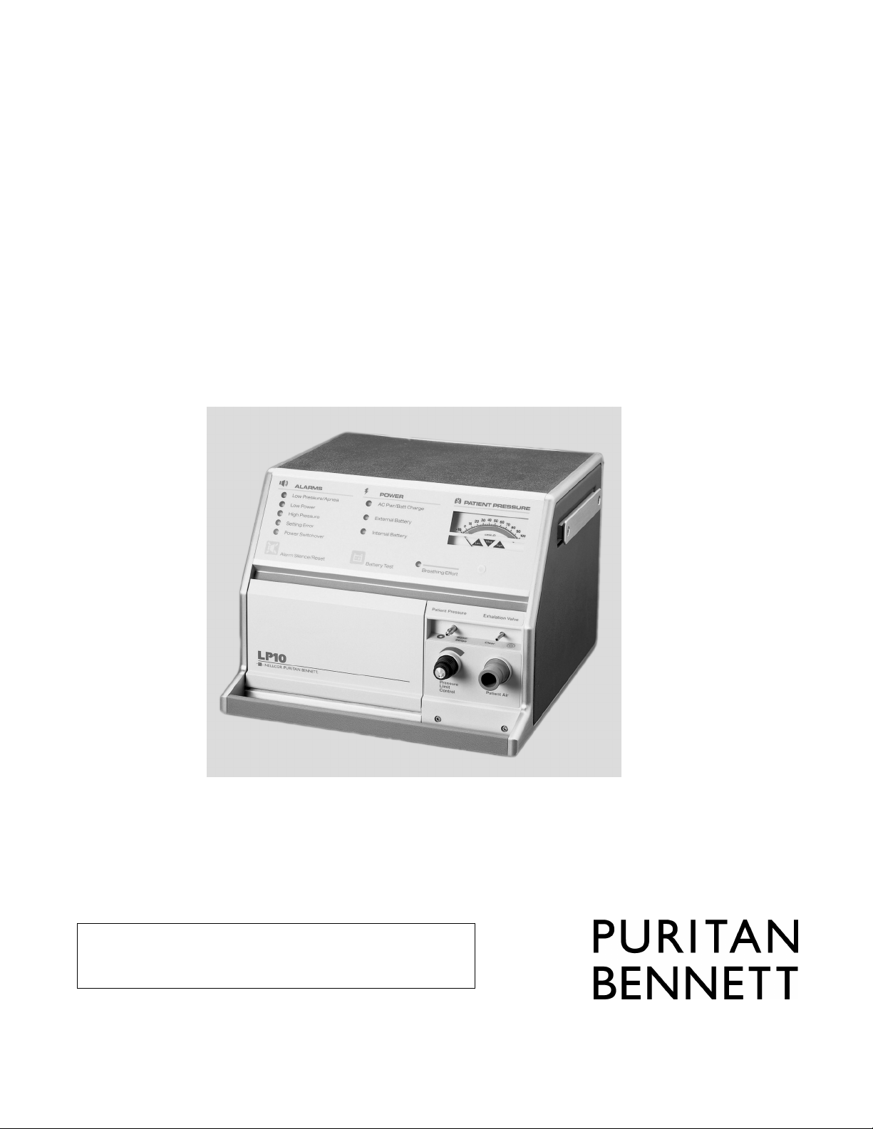
LP6 Plus Volume Ventilator
-AndLP10 Volume Ventilator
With Pressure Limit
Clinician’s Manual
Important Note: Read this manual in its entirety
before using the ventilator. Keep this manual for future
reference.
Page 2

For more information: Contact your Puritan Bennett representative for information on our full line of medical
equipment and related services. Or, you may contact Puritan Bennett Inc. directly.
Puritan Bennett Technical Services: 1.800.255.6774
Page 3

Contents
Introduction . . . . . . . . . . . . . . . . . . . . . . . . . . . . . . . . . . . . . . . . . . . 1
Purpose of the Manual . . . . . . . . . . . . . . . . . . . . . . . . . . . . . . . . . . . . 1
Symbols and definitions . . . . . . . . . . . . . . . . . . . . . . . . . . . . . . . . . . . 2
Warnings and Cautions . . . . . . . . . . . . . . . . . . . . . . . . . . . . . . . . . 3
Electrical Interference . . . . . . . . . . . . . . . . . . . . . . . . . . . . . . . . . . . . 4
General Description . . . . . . . . . . . . . . . . . . . . . . . . . . . . . . . . . . . . 5
Alarm Condition . . . . . . . . . . . . . . . . . . . . . . . . . . . . . . . . . . . . . . . . 6
Responding to Alarms . . . . . . . . . . . . . . . . . . . . . . . . . . . . . . . . . . . . 6
Troubleshooting Guide . . . . . . . . . . . . . . . . . . . . . . . . . . . . . . . . . . . 8
Front Panel . . . . . . . . . . . . . . . . . . . . . . . . . . . . . . . . . . . . . . . . . . . . 10
Upper Section . . . . . . . . . . . . . . . . . . . . . . . . . . . . . . . . . . . . . . 11
Lower Left Section . . . . . . . . . . . . . . . . . . . . . . . . . . . . . . . . . . . 12
Lower Right Section . . . . . . . . . . . . . . . . . . . . . . . . . . . . . . . . . 13
Rear Panel . . . . . . . . . . . . . . . . . . . . . . . . . . . . . . . . . . . . . . . . . . . . 14
Operating Controls . . . . . . . . . . . . . . . . . . . . . . . . . . . . . . . . . . . . . . 16
Operating Modes . . . . . . . . . . . . . . . . . . . . . . . . . . . . . . . . . . . . . . . 18
Assist/Control . . . . . . . . . . . . . . . . . . . . . . . . . . . . . . . . . . . . . . 18
Assist/Control with Pressure Limit (LP10 Only) . . . . . . . . . . . . 18
SIMV (Synchronized Intermittent Mandatory Ventilation) . . . . 18
SIMV with Pressure Limit . . . . . . . . . . . . . . . . . . . . . . . . . . . . . 19
Pressure Cycle . . . . . . . . . . . . . . . . . . . . . . . . . . . . . . . . . . . . . . 19
Standby . . . . . . . . . . . . . . . . . . . . . . . . . . . . . . . . . . . . . . . . . . . 19
Ventilator Parameters . . . . . . . . . . . . . . . . . . . . . . . . . . . . . . . . . . . . 20
Volume . . . . . . . . . . . . . . . . . . . . . . . . . . . . . . . . . . . . . . . . . . . 20
Breath Rate . . . . . . . . . . . . . . . . . . . . . . . . . . . . . . . . . . . . . . . . 20
Inspiratory or I-Time . . . . . . . . . . . . . . . . . . . . . . . . . . . . . . . . 20
Breathing Effort . . . . . . . . . . . . . . . . . . . . . . . . . . . . . . . . . . . . 22
Pressure Alarms . . . . . . . . . . . . . . . . . . . . . . . . . . . . . . . . . . . . 22
Pressure Limit Control (LP10 Only) . . . . . . . . . . . . . . . . . . . . . . . . . 23
Power Sources . . . . . . . . . . . . . . . . . . . . . . . . . . . . . . . . . . . . . . . . . . 26
AC Power . . . . . . . . . . . . . . . . . . . . . . . . . . . . . . . . . . . . . . . . . 26
External Battery 12 Volt DC . . . . . . . . . . . . . . . . . . . . . . . . . . . 27
Using a Car Battery . . . . . . . . . . . . . . . . . . . . . . . . . . . . . . . . . . 27
Internal Battery 12 Volt DC . . . . . . . . . . . . . . . . . . . . . . . . . . . 28
Routine Safety Check . . . . . . . . . . . . . . . . . . . . . . . . . . . . . . . . . . . . 29
Monthly Safety Check . . . . . . . . . . . . . . . . . . . . . . . . . . . . . . . . . . . 31
Installation . . . . . . . . . . . . . . . . . . . . . . . . . . . . . . . . . . . . . . . . . . 34
Mounting or Positioning . . . . . . . . . . . . . . . . . . . . . . . . . . . . . . . . . 34
Page iii
Page 4

Emergency Vehicle . . . . . . . . . . . . . . . . . . . . . . . . . . . . . . . . . . 35
Wheelchair . . . . . . . . . . . . . . . . . . . . . . . . . . . . . . . . . . . . . . . . 36
Power Connections . . . . . . . . . . . . . . . . . . . . . . . . . . . . . . . . . . . . . . 37
General . . . . . . . . . . . . . . . . . . . . . . . . . . . . . . . . . . . . . . . . . . . 37
AC Power . . . . . . . . . . . . . . . . . . . . . . . . . . . . . . . . . . . . . . . . . 37
External Battery 12 Volt DC . . . . . . . . . . . . . . . . . . . . . . . . . . . 38
Battery Performance . . . . . . . . . . . . . . . . . . . . . . . . . . . . . . . . . 39
Testing the Batteries . . . . . . . . . . . . . . . . . . . . . . . . . . . . . . . . . 40
Special precautions when using an external battery . . . . . . . . . . 41
Internal Battery 12 Volt DC . . . . . . . . . . . . . . . . . . . . . . . . . . . 42
Patient Ventilator Circuit . . . . . . . . . . . . . . . . . . . . . . . . . . . . . . . . 44
Exhalation Manifold . . . . . . . . . . . . . . . . . . . . . . . . . . . . . . . . . . . . . 46
Humidification . . . . . . . . . . . . . . . . . . . . . . . . . . . . . . . . . . . . . . . . 46
Short Term . . . . . . . . . . . . . . . . . . . . . . . . . . . . . . . . . . . . . . . . 46
Extended Use . . . . . . . . . . . . . . . . . . . . . . . . . . . . . . . . . . . . . . 46
Supplemental Oxygen . . . . . . . . . . . . . . . . . . . . . . . . . . . . . . . . . . . 48
Methods . . . . . . . . . . . . . . . . . . . . . . . . . . . . . . . . . . . . . . . . . . 48
Accessories . . . . . . . . . . . . . . . . . . . . . . . . . . . . . . . . . . . . . . . . . . . . 50
Positive End Expiratory Pressure (PEEP) . . . . . . . . . . . . . . . . . . 51
Pressure Monitoring . . . . . . . . . . . . . . . . . . . . . . . . . . . . . . . . . 53
Supplemental Oxygen . . . . . . . . . . . . . . . . . . . . . . . . . . . . . . . . 53
Humidification . . . . . . . . . . . . . . . . . . . . . . . . . . . . . . . . . . . . . 53
Remote Alarm . . . . . . . . . . . . . . . . . . . . . . . . . . . . . . . . . . . . . 54
Printer . . . . . . . . . . . . . . . . . . . . . . . . . . . . . . . . . . . . . . . . . . . 54
Cleaning and Maintenance . . . . . . . . . . . . . . . . . . . . . . . . . . . . . 55
Patient Circuit and Humidifier . . . . . . . . . . . . . . . . . . . . . . . . . . . . 56
Inlet Air Filter . . . . . . . . . . . . . . . . . . . . . . . . . . . . . . . . . . . . . . . . . 57
Ventilator Surface . . . . . . . . . . . . . . . . . . . . . . . . . . . . . . . . . . . . . . . 57
Storage of the Ventilator . . . . . . . . . . . . . . . . . . . . . . . . . . . . . . . . . . 58
Scheduled Maintenance . . . . . . . . . . . . . . . . . . . . . . . . . . . . . . . . . . 59
Service Policy . . . . . . . . . . . . . . . . . . . . . . . . . . . . . . . . . . . . . . . . . 60
Specifications . . . . . . . . . . . . . . . . . . . . . . . . . . . . . . . . . . . . . . . . . 61
Limited Warranty . . . . . . . . . . . . . . . . . . . . . . . . . . . . . . . . . . . . . 64
Keyword Index . . . . . . . . . . . . . . . . . . . . . . . . . . . . . . . . . . . . . . . 65
Page iv
Page 5

Introduction
Purpose of the Manual
This Clinician’s Manual will help you understand the operation of the
LP6 Plus and LP10 Volume Ventilators. It provides detailed information for
physicians and other clinical personnel about the installation, safe use, and verification of the operation of the LP6 Plus and LP10 Volume Ventilators. It
provides the caregiver guidelines for safe ventilation that are specific to the
ventilator. It is not a complete maintenance document. Therefore, it contains
no disassembly, repair, or reassembly instructions or diagrams.
Carefully read and understand all instructions before using the ventilator. Use the instructions contained herein in conjunction with those set by
the patient’s physician. No instruction in this manual is intended to replace
accepted medical practice regarding the use of the ventilator or the care of
the patient.
As you read this manual, you will notice Cautions and Warnings in boxes
on many pages. Pay very special attention to these boxes. They will tell you
what to do and what to avoid as you use the ventilator.
The difference between Warnings and Cautions is:
A Warning contains information about possible hazards to the patient, the
care provider, or the service technician.
A Caution includes information about how to avoid equipment damage.
The Notes and Accessories sections found at the back of this manual are for
your use in applying this manual’s information to a specific patient. Puritan
Bennett-supplied accessories include information concerning their use with
the ventilator.
Page 1
Page 6

Symbols and definitions
Symbols and definitions
The following symbols appear on the LP6 Plus and LP10 ventilators.
LP6 Plus and LP10 Clinician’s Manual
O
!
V
A
I
Power switch ON position, connection to mains power
Power switch OFF position, disconnection from mains power
Attention, consult accompanying manual.
Alternating current
Direct current
Volts
Amperes
Standby mode of operation
Canadian Standards Association
Battery test switch
Alarm silence switch
Alarm
Page 2
Power
Underwriters Laboratory
Patient pressure
External battery connection
Remote alarm
Battery test level
Manual reset
Page 7

Warnings and Cautions
Warnings
Always follow the physician’s prescription when using the ventilator.
Always operate and store the ventilator according to the specifications and instructions set forth in this manual.
Use only Puritan Bennett-approved accessories and products
with the ventilator. The use of other accessories may damage the
unit and endanger the patient.
Perform daily and monthly verification of the ventilator’s operation as identified in this manual.
Always stabilize and verify ventilator performance before connecting the patient to the unit.
All alarms indicate a potential risk to patient safety. When an
alarm sounds, provide immediate attention, care, and support to
the patient as dictated by the situation.
The LP6 Plus and LP10 ventilators shall not be used with flammable anesthetic agents.
Do not use in direct sunlight.
Cautions
Refer any adjustments or procedures exceeding the scope of this
manual to an Puritan Bennett Technical Service Representative.
Refer to the Puritan Bennett Service Policy on page 62.
Caution: Federal Law (U.S.A.) restricts this device to sale or use
by or on the order of a licensed physician.
Page 3
Page 8

Electrical Interference
Electrical Interference
LP6 Plus and LP10 Clinician’s Manual
Caution
Warning
Your ventilator is an electronic instrument. Any electronic instrument is subject to electrical interference. Electrical interference in
excess of 10 V/m may keep your ventilator from working properly.
Television sets, cordless or cellular telephones, microwave ovens, air conditioners, food processors, and other appliances can be sources of electrical interference. To avoid electrical interference between your ventilator
and these appliances, you must follow these instructions:
• Never place your ventilator near these appliances.
• Never plug the ventilator into the same A.C. electrical outlet as
these appliances, nor into electrical outlets on the same circuit as
these appliances.
• Never place the cables from ventilator accessories near these appli-
ances.
Electrical interference may keep your ventilator from working
properly, which may create a hazard to the patient.
Page 4
Note The ventilator is exempt under Section 15.801 (c)(5) of the no interfer-
ence regulations adopted by the FCC. If television interference does
occur, contact Technical Services at Puritan Bennett, Inc. or a television
repair technician for suggestions. Or, move the television to an A.C.
electrical outlet that does not allow interference.
Page 9
General Description
The Puritan Bennett LP6 Plus and LP10 Volume Ventilators are intended
for use in a non-acute care institution or transport, on pediatric and adult
patients. It is to be operated in accordance with the product labeling contained in this instruction manual.
The LP6 Plus and LP10 Volume Ventilators are microprocessor-controlled
volume ventilators. They provide continuous respiratory support for patients
with respiratory insufficiencies in a skilled nursing facility or hospital, or
during transport. Because of the compact design and light weight, the units
are highly portable.
The ventilators offer a wide range of delivery volumes, inspiratory times, and
breathing rates. The physician or the respiratory therapist can set the appropriate ventilation via the controls located in the recessed front panel. The
magnetically latched door panel and the control knobs are designed to prevent tampering and accidental resetting.
Audible and visual alarms quickly identify problems. See pages 6 through 9
for a complete discussion of these alarms.
Page 5
Page 10
Alarm Condition
Alarm Condition
LP6 Plus and LP10 Clinician’s Manual
Warnings
All alarms indicate a potential risk to patient safety. When an
alarm sounds, provide immediate attention, care, and support to
the patient as dictated by the situation.
Any device is subject to unpredictable failures. To ensure patient
safety, an appropriately trained caregiver should monitor ventilation. If the patient’s condition warrants the use of an independent secondary alarm, remote alarm, or another external
monitoring device, the physician should prescribe it. The physician should also determine to what level the patient may require
an alternate means of ventilation.
Certain types of ventilators, including the LP Series, have a Low
Inspiratory Pressure Alarm. The purpose of this alarm is to alert
the clinician or caregiver when the pre-set alarm parameters are
violated. As set forth in the LP Series Clinician’s and User’s
Manuals, a number of environmental factors and circuit accessories/components can affect the pressure in the breathing circuit.
These factors may prevent circuit pressure from violating the
low-pressure parameters, even in the event of a circuit being disconnected from the patient. Therefore, it is important for the clinician to consider and monitor these environmental factors when
establishing pressure alarm parameters. Depending on the specific clinical situation (e.g., risk of disconnect perceived as high,
patient is ventilator dependent) a secondary means of monitoring
ventilation (e.g., pulse oximetry) should be considered.
Responding to Alarms
The ventilator has visual and audible alarms. The audible alarm is usually a pulsating tone. Both the ventilator and the remote alarm emit
these tones. Flashing or steady light(s) on the ventilator indicate the
source of the problem.
A Pulsating Audible Alarm and Flashing Light(s):
The Low Power, High Pressure, Setting Error, and Power Switchover
alarms all use this type of alert signal.
Page 6
Page 11

LP6 Plus and LP10 Clinician’s Manual
Note In Assist/Control and SIMV modes, the High Pressure Alarm sounds
Responding to Alarms
A Steady Audible Alarm and Steady Lights:
This combination indicates a detected microprocessor error in the ventilator.
Single Reminder Tone:
A single tone sounds every five minutes when the internal battery powers the ventilator.
whenever the air pressure exceeds the selected high pressure limit. In the
Pressure Cycle mode, however, the High Pressure Alarm sounds only
when the air pressure exceeds the selected high pressure limit by 10
cmH2O/hPa.
When an alarm sounds:
First, attend to the patient immediately. Then, check the flashing or
steady light(s) on the ventilator to identify the source of the problem.
You may press the Alarm Silence/Reset button to silence the alarm. This
turns off the signal for one minute. If the alarm condition is corrected
during that minute, the alarm light will turn off.
A microprocessor error cannot be silenced. You cannot silence an alarm
before it occurs.
Note If a High Pressure, or Setting Error alarm condition is corrected before
you press Alarm Silence/Reset, the audible alarm will stop but the light
will continue to flash. Press Alarm Silence/Reset to turn off the light.
If a Low Pressure/Apnea, Low Power or Power Switchover alarm condition is corrected before you press Alarm Silence/Reset, both the audible
and visual alarms will continue. You must press Alarm Silence/Reset to
turn off the audible alarm and the light.
Warning
If alarms continue to sound, provide another means of ventilation and contact your homecare dealer.
Page 7
Page 12

Troubleshooting Guide
Troubleshooting Guide
Conditions Probable Cause Solution
LP6 Plus and LP10 Clinician’s Manual
All lights turn on and audible alarm sounds
Low Pressure/Apnea Alarm:
Pulsating audible tone with
flashing light
Normal condition. Alarms test when
unit is turned on.
Normal; manual alarm test. Alarms will stop in one second.
Microprocessor error. Turn vent off and set mode to Standby.
The patient is not breathing. Check the patient for breathing effort.
Leaks or loose connections in the
patient circuit.
Water in small-bore tubing. Inspect and remove water from small-
Crimped small-bore tubing. Uncrimp the small-bore tubing.
PEEP pressure set higher than the Low
Alarm control setting.
The patient’s breathing effort is less
than the Breathing Effort control setting.
Alarms will stop in two seconds.
Wait a few seconds. Return switches to
prescribed settings. If alarm persists,
provide another means of ventilation.
Check connection of the patient circuit
to the ventilator; check all connections
for leaks and tightness, especially at the
humidifier, trach tube, and exhalation
valve.
bore tubing.
Set Low Alarm control setting higher
than the PEEP pressure.
Set Breathing Effort so the patient’s
breathing effort turns on the Breathing
Effort light.
Page 8
Patient speech or other activities lower
patient airway pressure.
Low alarm setting is higher than Pressure limit setting. (LP10 only)
Volume set below patient’s tidal volume.
Pressure Limit level is set too low. (LP10
only)
Incorrect control settings. Reset to prescribed values.
Leaks or obstructions in the patient circuit.
Other causes. Notify your physician and your home-
Low pressure alarm sounds whenever
low pressure limit is not reached for two
consecutive breaths. Review the section
on alarms.
Correct to the prescribed value.
Correct to the prescribed value.
Correct to the prescribed value.
Check for leaks or crimped tubing.
care dealer
Page 13

LP6 Plus and LP10 Clinician’s Manual
Conditions Probable Cause Solution
Troubleshooting Guide
Low Power Alarm: Pulsating
audible tone with flashing
light
High Pressure Alarm:
Pulsating audible tone with
flashing light
Setting Error Alarm Inappropriate setting or settings beyond
Failure to recharge the Internal battery. Operate the ventilator on AC power for
Water in the tubing. Remove water from tubing.
Crimped tubing. Straighten crimped tubing.
Coughing or other high-flow expiratory efforts.
Patient inspiratory resistance or compliance changes.
A sticky Pressure Limit control. Occlude the end of the patient circuit to
Airway obstruction Check for trach obstruction or for a
Malfunction in the exhalation manifold. See the manifold manufacturer’s
Pressure Limit setting is higher than the
High Alarm setting. (LP10 only)
the capabilities of the machine.
at least three hours, or place ventilator
in Standby Mode while on AC power;
use backup ventilator.
Treat patient’s cough. The alarm is
appropriate for these conditions.
Have physician determine new ventilator settings.
free the valve.
condition in which the patient requires
suctioning.
instructions.
Reset both to the prescribed values.
Readjust settings to the physician’s prescription.
Dirty inlet filter. Replace filter.
Internal Battery light flashes Unit has not switched to external bat-
tery.
DC circuit breaker is open. Reset by pushing in protruding rod.
Single tone Unit is operating on internal battery. Check for unconnected or miscon-
Green AC Power light does
not glow
Warning
AC circuit breaker is open. Turn it back ON.
AC power cord is not connected. Plug in the cord.
No power at the wall outlet. Use an active outlet.
If the problems continue, provide another means of ventilation
Check for unconnected or misconnected battery cable. Check for blown
fuse in the battery cable. Use another
external battery.
nected battery cable. Check for blown
fuse in the battery cable. Use another
external battery.
and contact your homecare dealer.
Page 9
Page 14
Front Panel
Front Panel
LP6 Plus and LP10 Clinician’s Manual
Page 10
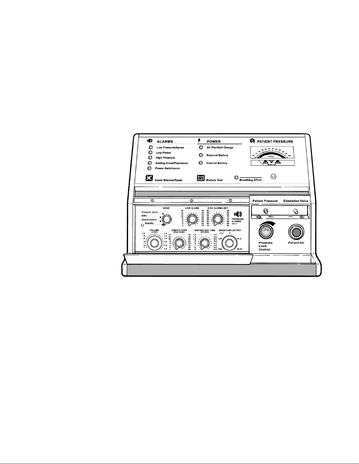
The Front Panel of the ventilator has three sections:
• The upper section has small lights, two touch button pads, and a
meter.
• The lower left section has the operating controls. The physician pre-
scribes their setting. To prevent accidental resetting, they are behind
a closed panel.
• The lower right section has the Pressure Limit control and the con-
nections for the Patient Circuit.
Page 15

LP6 Plus and LP10 Clinician’s Manual
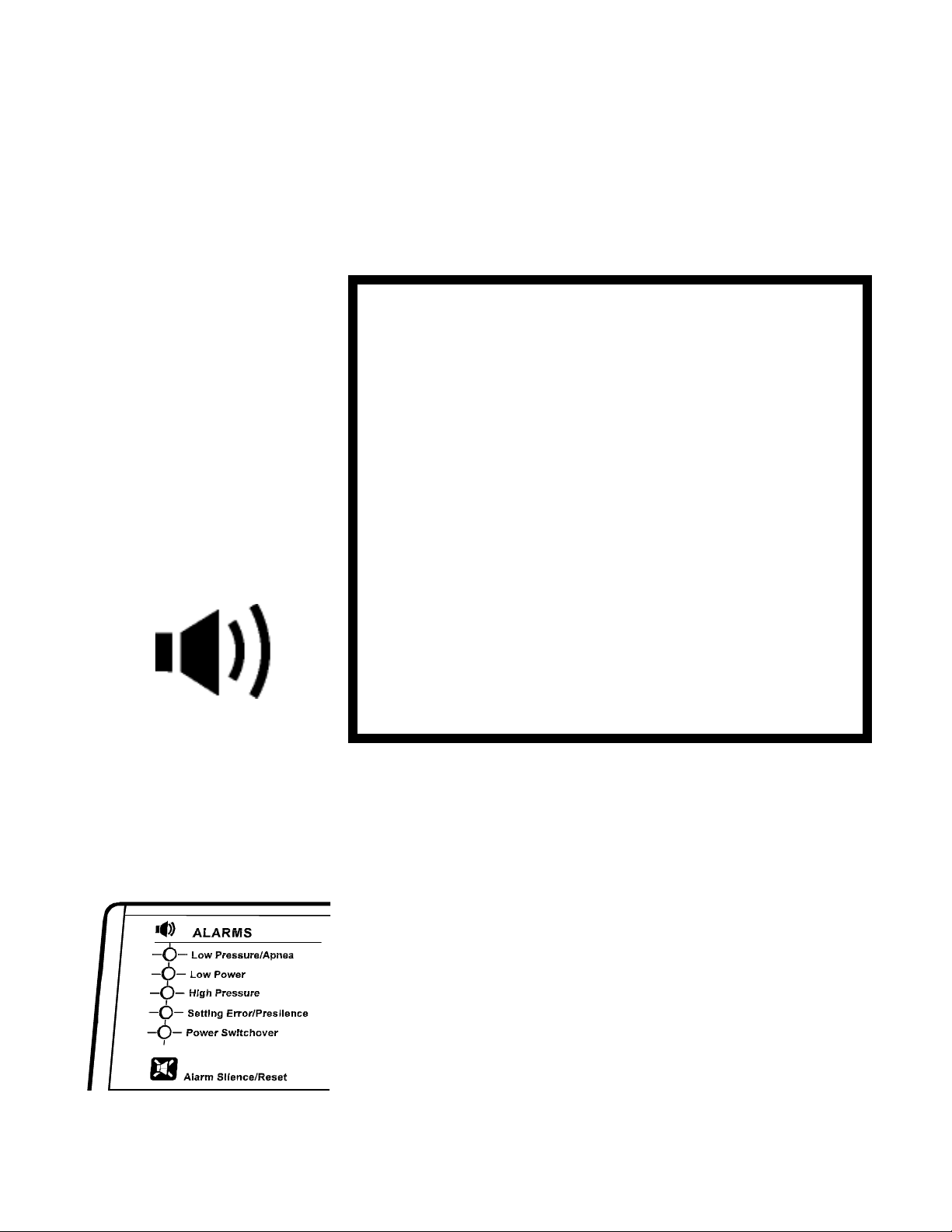
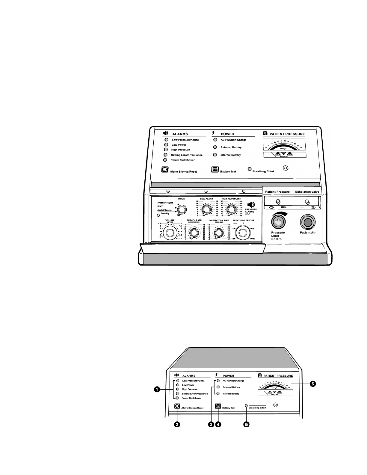
Upper Section 1. Alarm Lights: When flashing or continuously lit, they identify a
Front Panel
condition that demands immediate attention. There is also an audible tone when these lights begin flashing.
2. Alarm Silence/Reset Button: This has five uses.
• Push to test the alarms.
• Push to silence alarms for 60 seconds.
• Push to reset the alarm after correcting the problem.
• Push simultaneously with the Battery Test Button for operating
hours. (See the Scheduled Maintenance portion of the manual, page
60.)
• Use this button with other controls to start the self-test. (See page
30.)
3. Power Source Lights:
• The top light is green when the ventilator is AC powered.
• The middle light is amber when an external battery powers the ven-
tilator.
• The bottom light flashes amber when the ventilator’s internal bat-
tery is in use. A single tone also beeps every five minutes.
4. Battery Test Button: It has four uses.
• When pressed, the Pressure Meter displays the charge status of the
battery in use (internal or optional external battery).
• Push simultaneously with the Alarm Silence/Reset button for an
indication of operating hours. (See the Scheduled Maintenance portion of this manual, page 56.)
• Press the button to print a report from an attached printer.
• Use this button with other controls to start the self test. (See page
30.)
5. Breathing Effort Light: This light turns green whenever the venti-
lator senses the patient’s effort to breathe. The Breathing Effort control sets the sensitivity.
6. Patient Pressure Meter: The meter displays three pieces of infor-
mation:
• Pressure at the Exhalation Manifold.
• The number of hours of ventilator operation.
• The charge status of the internal or attached external battery.
Page 11
Page 16
Front Panel
Lower Left Section
LP6 Plus and LP10 Clinician’s Manual
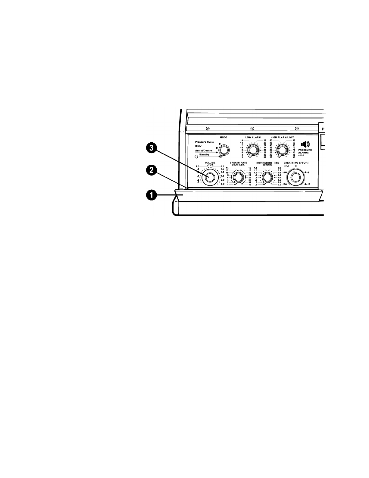
1. Control Panel Door: This door is latched magnetically to pro-
tect the controls from accidental resetting.
2. Alarm Reference Guide: Consult this guide for a summary of
alarms and the action you should take. You will find the Guide on
the inside of the Control Panel Door.
3. Control Knobs: They are behind the closed Control Panel Door.
The patient’s physician prescribes the settings for these controls. See
pages 16 through 22 for details.
Page 12
Page 17
LP6 Plus and LP10 Clinician’s Manual
Lower Right Section
Front Panel
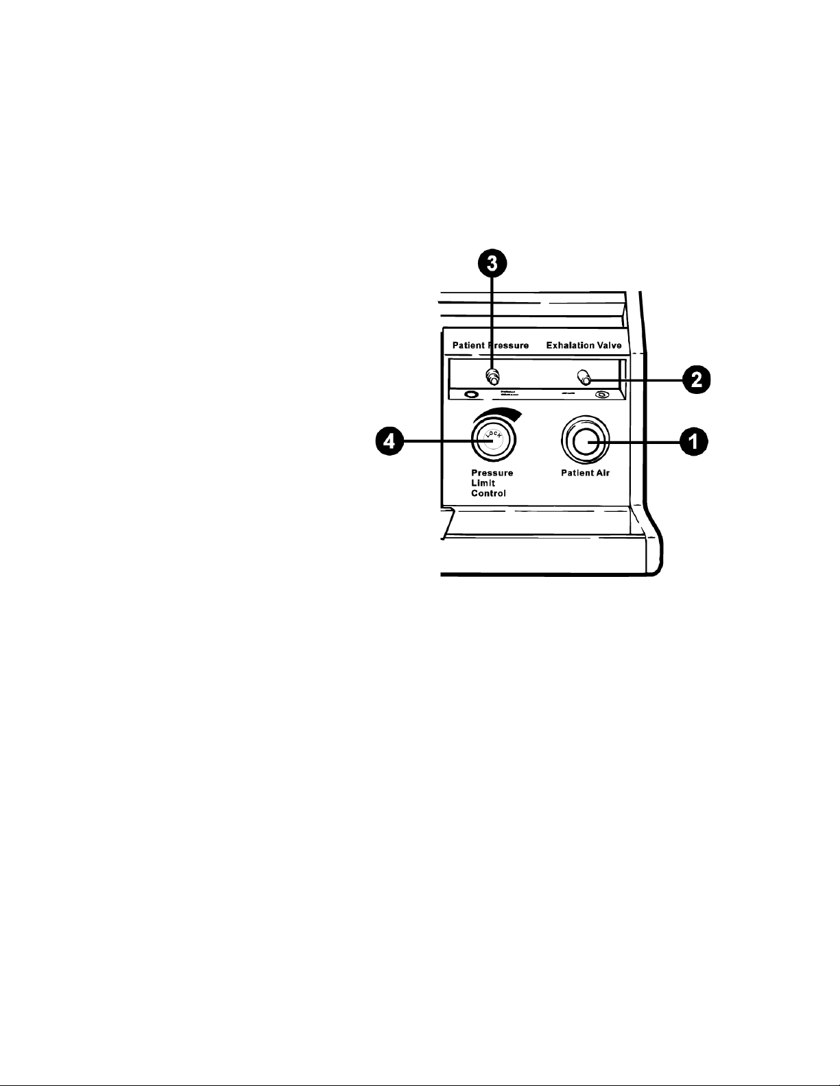
1. Patient Air Tube: The Patient air hose connects to this tube. The
ventilator delivers air through this tube.
2. Exhalation Valve Port: The Exhalation Pressure Tube of the
Patient Circuit connects to this port.
3. Patient Pressure Port: The Patient Pressure Tube of the Patient
Circuit connects to this port.
4. Pressure Limit Control (LP10 Only): This control sets the air pres-
sure limit during a forced or assisted breath. For use in Assist/Control or SIMV modes only; use in other modes may not allow effective
ventilation. See pages 23 through 25.
Page 13
Page 18
Rear Panel
Rear Panel
Vent
AC Plug
Carrying
Handle
External
12 Volt DC
Battery
LP6 Plus and LP10 Clinician’s Manual
Remot e Ala rm
Connector
Mounting
Rails
14
Inlet
Filter
1
11
Pressure
Relief
10
9
8
6
7
DC Circuit
Breaker
12
Communi-
cation Port
4
5
Serial Num-
ber Plate
Page 14
2
Cord Wrap
Rear Feet
13
Voltage
Select
3
AC Power
Switch
Page 19

LP6 Plus and LP10 Clinician’s Manual
Rear Panel
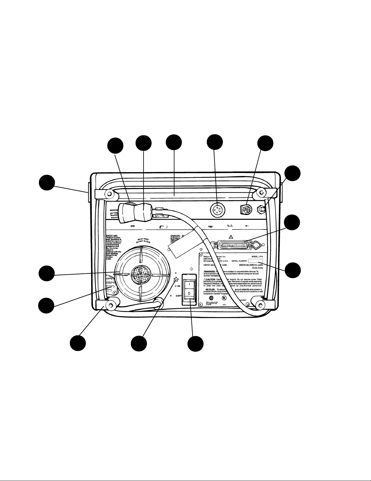
1. Inlet Filter: The ventilator draws in air through this filter.
Warning
Do not block the inlet filter. (Keep away from curtains.)
2. Cord Wrap and Rear Feet: There is a foot at each corner.
3. AC Power Switch/Circuit Breaker: This is the ON/OFF switch
for AC power. It also has a built-in circuit breaker. 1 is power connected to mains and 0 is power disconnected from mains.
4. Communications Port: A special cable fits here and leads to an
optional printer.
Note The ventilator and printer should be turned off before connection or dis-
connection of the printer.
5. Serial Number Plate: This has Puritan Bennett’s identification
number for the ventilator. It also lists the unit’s power requirements.
6. External 12 Volt DC Battery Connector: This is where you plug
in an external battery cable.
7. Remote Alarm Connection: A remote alarm (optional) can sum-
mon the caregiver when an alarm sounds.
8. Rear Carrying Handle Recess
9. AC Plug Holder
10. Vent: Warm air from the unit’s circuitry leaves the ventilator and
cool air enters through this vent. This cools the ventilator.
Warning
Warning
Caution
Do not block rear panel vent
11. Pressure Relief: This prevents the air pressure from exceeding
approximately 100 cmH
Do not block the pressure relief valve.
12. DC Circuit Breaker: This circuit breaker protects the ventilator
O/hPa.
2
when it is powered by an external battery.
13. Voltage Select Switch: This switch selects 110 or 220 volts when it
is powered by an external battery
An incorrect switch setting may damage your ventilator.
14. Mounting Rails: These are used to mount and connect accessories to
the ventilator.
Page 15
Page 20
Operating Controls
Operating Controls
LP6 Plus and LP10 Clinician’s Manual
Warning
Warning
Periodically check the control settings to be sure they are at the
prescribed setting. Always verify that the controls are set correctly
before connecting and using the ventilator. Do not change them
without a physician’s orders.
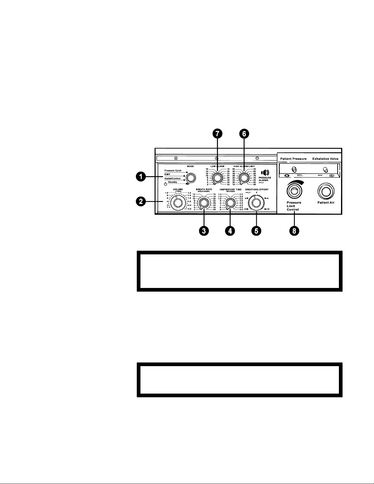
1. Mode: This control selects the operating mode for the ventila-
tor.
2. Volume: This sets the amount of air the patient receives for each
breath. To change the setting, push in the control and then turn it to
the selected setting. Any change made during operation results in a
maximum change of 100 milliliters from breath to breath until the
new volume is reached.
For more precise accuracy in setting the volume control (indicator), the use of an external volume measuring device is recommended.
3. Breath Rate: This setting controls the minimum number of breaths
per minute (BPM) delivered by the ventilator.
4. Inspiratory Time: This sets the time it takes for the ventilator to
deliver a breath.
Page 16
Page 21

LP6 Plus and LP10 Clinician’s Manual
Operating Controls
5. Breathing Effort: This adjusts the ventilator’s sensitivity to the
patient’s breathing effort. When the patient’s effort reaches the setting, the Breathing Effort light turns on and the ventilator delivers a
breath. Push in the control knob to change the setting.
6. High Alarm/Limit: This sets the point at which the High Pressure
alarm will sound. If the pressure exceeds this limit, the High Pressure alarm sounds (except in the Pressure Cycle mode). Delivery of
this breath stops after the pressure reaches this limit. The audible
alarm is automatically silenced if the following breath does not
exceed the setting.
Often, when the high alarm sounds, the patient circuit has an
obstruction. Clearing the circuit will stop the alarm.
7. Low Alarm: This establishes the pressure which must be exceeded
with “controlled” or "assisted" breath. The alarm sounds only when
two consecutive breaths do not reach the selected limit, or if the
limit is reached but the pressure fails to return to a level below the
limit. Normally, this setting is just below the pressure you need for
proper ventilation.
If this alarm sounds, look for a leak in the patient circuit. A leak or
disconnection of the circuit is often the cause for the alarm.
Note Some circuit components will prevent a Low Pressure alarm by keeping
the pressure in the circuit above the alarm limit. Examples of these components include hydrated heat and moisture exchangers (HMEs) and tracheostomy tubes. If the patient circuit is disconnected from the patient,
but still connected to these components, a Low Pressure alarm may not
sound.
Where such disconnections from a ventilator-dependent patient are possible, you must set the Low Pressure alarm to a level that permits an
alarm to sound. To do this, simulate the disconnection; if a Low Pressure/Apnea alarm does not sound after two breath cycles, increase the
alarm limit until an alarm sounds.
8. Pressure Limit (LP10 Only): This limits the maximum pressure
developed for each breath. For use with Assist/Control or SIMV
modes only; use in other modes may not allow effective ventilation.
See Operating Modes section, below, for details.
Page 17
Page 22

Operating Modes
Operating Modes
Assist/Control In this mode, if the breathing effort is strong enough to trigger the
Breathing Effort light, the ventilator assists breathing. The ventilator
then delivers the selected prescribed volume of air. If the patient makes
no effort to breathe and, thus, fails to activate the Breathing Effort light,
the ventilator takes control. It delivers breaths at the selected rate.
Breath Rate set at 1 - 5 BPM
If the patient does not start a breath on his/her own for 10 seconds, the
Apnea alarm sounds and alerts the caregiver. Meanwhile, the ventilator
delivers breaths at 10 BPM at the selected volume.
Breath Rate set at 6 BPM or more
No alarms sound if the patient fails to start a breath. The ventilator continues to deliver breaths at the selected rate and volume.
LP6 Plus and LP10 Clinician’s Manual
Assist/Control with
Pressure Limit (LP10 Only)
Note Since the pressure limit function bleeds off air to limit pressure, the vol-
SIMV (Synchronized
Intermittent Mandatory
Ventilation)
The ventilator functions as described under the Assist/Control mode.
The only difference is that the ventilator will limit the pressure during a
delivered breath.
ume of air delivered will be less than the set value.
In this mode, the patient can breathe unassisted and on his/her own
between ventilator delivered breaths. The ventilator monitors these
spontaneous breaths.
If the patient’s effort is not strong enough to turn on the Breathing
Effort light or the patient makes no effort, the ventilator delivers a controlled breath. All this depends on the breath rate setting:
Breath Rate set at 1 - 5 BPM
If the patient does not start a breath on their own for 20 seconds, the
Apnea alarm sounds and alerts the caregiver. Meanwhile, the ventilator
delivers breaths at 10 BPM at the selected volume.
Breath Rate set at 6 BPM or more
No alarms sound if the patient fails to start a breath. The ventilator continues to deliver breaths at the selected rate and volume.
Page 18
Page 23

Operating Modes
LP6 Plus and LP10 Clinician’s Manual
SIMV with Pressure Limit The ventilator functions as described under the SIMV mode. The only
difference is that the ventilator will limit the pressure during a delivered
breath.
Pressure Cycle In this mode, the ventilator assists or controls the patient’s breathing as
it does in the Assist/Control mode. But, there’s a difference. If the air
pressure exceeds the level set on the High Alarm/Limit, delivery of the
breath is stopped and the high pressure alarm does not sound. The high
pressure alarm sounds only if the air pressure happens to exceed the
High Alarm/Limit by 10 cmH
O/hPa.
2
Note The high pressure alarm sounds only if the air pressure happens to
exceed the limit by 10 cmH2O/hPa.
Breath Rate set at 1 - 5 BPM
If the patient does not start a breath on his/her own for 10 seconds, the
Apnea alarm sounds and alerts the caregiver. Meanwhile, the ventilator
delivers breaths at 10 BPM.
Breath Rate set at 6 BPM or more
No alarms sound if the patient fails to start a breath. The ventilator continues to deliver breaths at the selected rate and volume.
Warning
In this mode, when the pressure reaches the level of the High
Alarm/Limit, the ventilator is designed to cycle into expiration
without sounding an alarm. It is unlikely that the pressure will
exceed the set limit by 10 cmH
O/hPa.
2
Standby The ventilator will not deliver breaths with the control in this mode. It
will, however, charge the internal or connected external battery, but
only when the AC Pwr/Batt charge is ON with the unit plugged into a
wall outlet. The patient may breathe through the patient circuit in this
mode.
External and internal batteries charge equally well in all Modes.
Page 19
Page 24

Ventilator Parameters
Ventilator Parameters
Volume Set the delivered, or tidal volume, with the front panel Volume control.
This push-to-turn knob sets the piston excursion. Its range is from 100
to 2200 ml.
Breath Rate Adjust the rate (breaths per minute) with the Breath Rate control. Incre-
ments are 1 BPM for rates of 1 to 20 BPM, and 2 BPM for rates of 22 to
38 BPM. To find the maximum inspiratory flow rate, see the upper table
on the next page.
LP6 Plus and LP10 Clinician’s Manual
Inspiratory or I-Time This control adjusts the rate at which the prescribed tidal volume is
delivered to the patient’s lungs. Increments are 0.1 seconds for times of
0.5 to 1.0 seconds and 0.5 seconds from 1.5 to 5.5 seconds. You may also
select an intermediate setting of 1.2 seconds.
Inspiratory time and Breath Rate determine both the Expiratory time
and the I:E ratio. The Volume and Inspiratory Time setting determine
the flow rate. (Example: 1.0 liters of vol. @ 1.0 sec Inspiratory Time =
60 LPM flow rate.) See the lower table on the next page.
Note Breath Rate and Inspiratory Time settings that produce an inverse I:E
ratio cause a Setting Error alarm. The ventilator will not deliver inverse
I:E ratios. It will deliver breaths at the set inspiratory time, an I:E ratio
of 1:1.
To determine the maximum inspiratory time or BPM values, use one of
these formulas:
30 divided by Inspiratory Time = Maximum Breath Rate, or
30 divided by Breath Rate = Maximum Inspiratory Time.
Page 20
Page 25

LP6 Plus and LP10 Clinician’s Manual
Ventilator Parameters
Page 21
Page 26

Ventilator Parameters
Breathing Effort This push-to-turn knob sets the patient effort needed to trigger an
LP6 Plus and LP10 Clinician’s Manual
assisted breath. It also sets the effort needed to reset the Apnea BPM rate
with breath rates from 1 to 5 BPM. The settings are continuous from 10 to +10 cmH2O/hPa, with zero being atmospheric pressure. When
the patient’s breathing effort is sufficient, the green Breathing Effort
indicator lights up. Use the control settings above zero (the plus settings) to compensate for Positive End Expiratory Pressure (PEEP).
Warning
Positive Breathing Effort settings, without the use of PEEP, will
cause the ventilator to autocycle (i.e., deliver breaths based on the
selected inspiratory time at a 1:1 ratio).
Pressure Alarms Low Alarm sets the low pressure limit. The increments are 2 cmH
hPa for settings from 2 to 32 cmH2O/hPa. Adjust the setting to a value
just below the pressure necessary for proper patient ventilation.
The low pressure alarm sounds only when two consecutive breaths do
not reach the selected limit, or if the limit is reached but the pressure
fails to return to a level below the limit. You must manually reset the
low pressure alarm by pushing Alarm Silence/Reset.
The High Alarm/Limit control sets the high pressure limit. The high
pressure alarm sounds when the limit is exceeded in the Assist/Control
or SIMV operating modes or when the limit is exceeded by 10 cmH2O/
hPa in the Pressure Cycle mode. The inspiratory phase stops if the high
pressure limit is exceeded. The audible alarm is automatically silenced if
the following breath does not exceed the setting. The settings are 15 to
90 cmH
O/hPa with increments of 5 cmH2O/hPa.
2
Note Some circuit components will prevent a Low Pressure alarm by keeping
the pressure in the circuit above the alarm limit. Examples of these components include hydrated heat and moisture exchangers (HMEs) and tracheostomy tubes. If the patient circuit is disconnected from the patient,
but still connected to these components, a Low Pressure alarm may not
sound.
O/
2
Page 22
Where such disconnections from a ventilator-dependent patient are possible, you must set the Low Pressure alarm to a level that permits an
alarm to sound. To do this, simulate the disconnection; if a Low Pressure/Apnea alarm does not sound after two breath cycles, increase the
alarm limit until an alarm sounds.
Note Parameter settings beyond the capabilities of the machine will produce a
Setting Error alarm.
Page 27

Pressure Limit Control (LP10 Only)
LP6 Plus and LP10 Clinician’s Manual
Pressure Limit Control (LP10 Only)
The Pressure Limit Control is a mechanical, spring-loaded valve that
operates independently of the ventilator’s microprocessor. The control is
designed for optional use in the Assist/Control and SIMV operating
modes. It allows the ventilator to function like a pressure limited, timecycled ventilator.
Note Pressure limit control ventilation is intended for use with
uncuffed tracheostomy tubes, or in other patient circuit configurations which ensure an intentional artificial airway leak.
When the Pressure Limit Control is activated, the normal waveform of
the LP10-I Ventilator is altered and the ventilator provides extended or
plateaued pressures.
The figures below illustrate two printouts depicting waveforms with and
without Pressure Limit.
Flow
Pressure
Vol um e
Flow
Pressure
Vo lum e
Without Pressure Limit With Pressure Limit
Note The illustrations are actual reproductions of printouts from the printer.
Page 23
Page 28

Pressure Limit Control (LP10 Only)
Use the following instructions to activate and adjust the Pressure Limit
Control.
To set the Pressure Limit level on the LP10:
1. Disconnect the patient from the ventilator. Provide another
2. Turn the Pressure Limit Control counter-clockwise until it stops.
Note The outside ring of the knob must be pushed in before the center adjust-
ment knob can be moved.
3. Set all controls to the prescribed settings.
4. A guide for setting the Volume Control is a calculation based on the
LP6 Plus and LP10 Clinician’s Manual
means of ventilation.
This reduces the pressure to near zero.
patient’s body weight. This factor should be approximately 7 ml/lb
(18 ml/kg), or 100 ml, whichever is greater. Example: Patient
weight = 55 lbs., set volume at 385 ml. Note that the Volume Control setting is a prescribed setting.
Warning
5. Block the Exhalation Manifold at the port that connects to the
patient to observe the pressure on the Pressure Meter.
Wash hands thoroughly. Do not introduce germs or contaminants
into the patient circuit while performing this task.
6. Watch the needle on the Patient Pressure Meter. Note the highest
pressure achieved during a machine-delivered breath.
7. Turn the Pressure Limit Control clockwise in small increments each
breath until the meter needle reaches, but does not exceed, the pressure value prescribed by the physician.
8. When the prescribed Pressure Limit is reached, allow the machine to
cycle for several breaths to verify stable operation.
9. Reconnect the patient to the ventilator.
Page 24
Page 29

LP6 Plus and LP10 Clinician’s Manual
Pressure Limit Control (LP10 Only)
10. When you first connect the patient to the ventilator, the value of the
limited pressure may drop. (See Figures.) Watch the needle on the
Patient Pressure Meter. Slight increases in the Pressure Limit setting
may be required to increase the maximum pressure to the prescribed
limit. Allow the machine to cycle several breaths to verify stable
operation.
Pressure before patient
connection
11. Check to ensure that all settings are in agreement with the physi-
Pressure after patient
connection
cian’s prescription.
12. Monitor the patient and the ventilator closely.
13. Set high pressure alarm approximately 5 cmH
O/hPa above the
2
pressure limit.
Warning
The normal operation of the Pressure Limit control will not allow a
High Pressure alarm to occur, even when the tracheostomy tube or
the patient circuit is blocked. The High Pressure alarm will sound
only if the Pressure Limit valve fails to open.
Note Use a printer during setup and routine safety checks to confirm precise
opening pressure of the Pressure Limit Control.
Page 25
Page 30

Power Sources
Power Sources
LP6 Plus and LP10 Clinician’s Manual
When used in the hospital, plug the ventilator into a convenient wall
socket. If you use the ventilator in a wheelchair or in a car, connect it to
an external 12 Volt DC battery. Your ventilator has an internal battery.
Use the internal battery for short-term emergencies only, for example,
when moving from one power source to another. Make sure you recharge
the internal battery immediately after each use.
110
Warning
The batteries contain toxic chemicals and no attempt to remove or
replace the batteries should be made by any one other than the
homecare dealer or an authorized service center.
AC Power Plug the ventilator into an appropriate AC grounded wall outlet.
220
Warning
Warnings
The ventilator automatically operates from AC power when you plug it
in and the rear panel Power switch is on. Make sure that you plug the
cord into a properly grounded outlet.
The ventilator must be set to the proper voltage before plugging it
into the AC outlet.
The ventilator must be properly grounded when operating on AC
power. If you have any doubts about the outlet’s ground connection, have a qualified electrician examine the outlets.
AC power sources in ambulances and aircraft are frequently
unregulated. As a result, the ventilator may be exposed to high
voltage levels that can damage it. Operation of the ventilator on
improper power sources voids the warranty and will seriously
damage the unit.
Page 26
Do not use a power convertor as a power source for the ventilator.
Page 31

Power Sources
LP6 Plus and LP10 Clinician’s Manual
Your ventilator automatically recharges its internal battery whenever it
is:
• plugged into an AC outlet, and
• the AC Power Switch is ON (1)
You can also recharge an external battery that is properly connected to
your ventilator. See “Battery Performance” on page 39.
External Battery 12 Volt DC The ventilator can operate when properly connected to a 12 VDC exter-
nal battery. If the AC power fails, the ventilator will automatically
switch to an attached external battery. A Power Switchover alarm signals
the changes from AC to DC (the external battery).
Caution
Do not use the ventilator with a 24 VDC external battery.
A deep-cycle battery (74 amp-hour), in good condition, can power the
ventilator without recharging for about 20 hours. A gel-cell type battery
(34 amp-hour) can power the unit for about 10 hours before needing a
recharge. Though the ventilator can recharge an external battery, it is
less efficient than an Puritan Bennett-approved battery charger.
Recharge an external battery 3 hours for each hour of use. For the battery
test procedure, see page 40.
Note Do not reverse the positive and negative cables when connecting a bat-
tery to the ventilator. If you accidentally reverse the connections, a protective fuse in the battery cable or the ventilator’s DC circuit breaker
opens. The cable will not provide power to the ventilator. You must first
correct the connections and install a correct replacement fuse in the
cable. Reset the DC circuit breaker on the ventilator. Only then will the
external battery power the ventilator.
Cautions
Recharge an external battery immediately after use. You must use
an approved battery charger (available from Puritan Bennett) to
recharge external batteries used for extended periods of time. Do not
use the ventilator’s internal charger to recharge deeply discharged
batteries.
Never connect a battery charger to an external battery while the battery is connected to the ventilator.
Using a Car Battery The ventilator will operate from a car battery. Connect the ventilator to
the car with a cigarette plug cable from Puritan Bennett. Make sure the
vehicle is running when the ventilator is drawing power. Otherwise, the
ventilator may run down the car’s battery.
Page 27
Page 32

Power Sources
LP6 Plus and LP10 Clinician’s Manual
Caution
Always start the vehicle before connecting the ventilator to the car
battery. Starting a vehicle when the ventilator is connected may
damage the ventilator and void the warranty.
Internal Battery 12 Volt DC The ventilator automatically switches to its internal battery if the AC
power fails or the unit is disconnected from AC power and there is no
adequate external battery connected. The internal battery also automatically takes over when an external battery’s power becomes inadequate. A
power Switchover alarm signals the change to the internal power source.
The ventilator operates from 30 to 60 minutes on a fully charged internal battery. The time depends on many factors, primarily, the selected
settings. The amber Internal Battery light flashes continuously and an
audible alarm sounds every five minutes when the internal battery is in
use. When approximately five minutes of power remain, a continuous
Low Power alarm sounds. At this signal, immediately switch to
another power source. Use the internal battery only for emergency
power back-up.
If the internal battery is not used, exercise it every four to six weeks.
That is, run the ventilator on its internal battery until the low power
alarm sounds. Immediately switch to AC power and recharge the internal battery.
With AC power ON, the ventilator will recharge the internal battery in
any Mode, including Standby. Recharge a discharged internal battery for
at least three hours before turning off the ventilator. This action will
help prolong battery life.
Page 28
Warning
Caution
If the patient’s health or safety would be jeopardized by long-term
power failure, a reliable back-up power source is mandatory. Do
not regard the internal battery as a long-term back-up power
source.
Recharge the Internal Battery for at least three hours immediately
after use. An external battery cannot recharge the internal battery.
Page 33

LP6 Plus and LP10 Clinician’s Manual
Routine Safety Check
Note Use this information along with instructions from the patient’s physi-
cian. The procedure takes about ten minutes to complete and can be performed by a trained caregiver.
Routine Safety Check
Warning
Disconnect the patient from the ventilator and provide another
means of ventilation before starting these tests.
ALWAYS complete a routine safety check BEFORE connecting the
patient to the ventilator.
1. Check the Low Pressure Alarm.
• If the patient is not connected to the ventilator, connect a patient
circuit and test lung to the ventilator. Then turn the ventilator on
and switch it to an operating mode.
• Disconnect the small patient pressure tube from its port near the
bacteria filter. Wait for two or three breaths.
• The Low Pressure/Apnea light should start flashing and the audible
alarm should sound.
• Push the Alarm Silence/Reset button to silence the alarm.
• Reconnect the pressure tube to the ventilator. The Low Pressure/
Apnea light should stop flashing after a breath or two.
2. Check all the settings.
• Compare the current settings to your written record of the pre-
scribed settings.
• Make sure that all seven controls (located behind the front panel
door) are set to the doctor’s prescription.
3. Check the Patient Circuit.
• Check every connection in the circuit you are using or plan to use.
Make sure that the tubing is routed correctly, that all connections are
tight, and that there are no leaks.
• Check every part of the circuit for cracks and water. Each part must
be in good condition. There should be no water in any part of the
circuit.
Page 29
Page 34

Routine Safety Check
LP6 Plus and LP10 Clinician’s Manual
4. Check all the alarm signals.
• Turn the Mode switch to Standby.
• Wait one second and turn the Mode switch to Assist/Control.
• All nine lights (on the top section of the front panel) should turn on
and the audible alarm should sound for two seconds.
Note If the ventilator is not plugged in or if the AC power switch is off, only
eight lights will turn on. (The AC Power/Battery Charge light will not
turn on.)
• Any connected accessories that signal an alarm (such as a remote
alarm) also test their alarms.
• If the Power Switchover alarm is on, push the Alarm Silence/Reset
button to turn it off.
• Push the Alarm Silence/Reset button and hold for three seconds.
• All nine (or eight) lights should turn on and the alarms should sound
for one second. The accessories also signal their alarms for one second.
5. Perform a battery test.
Note If you do not have an external battery connected to the ventilator,
ignore the part of this test printed in italics.
• Make sure the ventilator is operating on AC power and the green AC
Power/Battery Charge light is on.
• Turn off the AC power by pushing the "0" on the AC power switch
located on the back panel.
• Make sure that the Power Switchover light starts flashing and the
alarm begins to sound. Push the Alarm Silence/Reset button to turn
it off.
• The External Battery light should be on.
• Press and hold the Battery Test button. The needle on the Patient Pressure
Meter will point to low, medium, or high (within the lower window). If the
needle points to low, recharge your external battery. See “Testing the Batteries” on page 40.
• Disconnect the external battery.
• Make sure that the Power Switchover light starts flashing and the alarm
sounds. Push the Alarm Silence/Reset button to turn them off.
• The Internal Battery light should be flashing.
• Press and hold the Battery Test button. The needle in the Patient
Pressure Meter will point to low, medium, or high (within the lower
window). If the needle points to low, recharge the internal battery
immediately after completing the daily safety check. See page 44.
Perform Battery test after 3 hours of recharging.
Page 30
Page 35

LP6 Plus and LP10 Clinician’s Manual
Monthly Safety Check
• Connect a fully charged external battery to the ventilator. Verify that the
External Battery light on the front panel turns on.
• Turn the AC power on. Make sure that the green AC Power/Battery
Charge light (located on the front panel) turns on.
Warning
If the ventilator does not pass the daily safety check or you cannot
complete this check, call your vent supplier or an Puritan Bennett
Service Representative immediately.
Monthly Safety Check
Note Use this information along with instructions from the patient’s physi-
cian. The tests take about ten minutes to complete.
Warning
Disconnect the patient from the ventilator for the monthly safety
check. Provide another means of ventilation before starting these
tests.
1. With the ventilator turned off, confirm that the pressure meter
is resting at -10 (±1.0) cmH2O/hPa.
2. Unplug the AC power cord. Visually inspect the plug and cord for
damage or exposed wires which could cause a shock hazard.
Warning
3. Check the High Pressure and Low Pressure alarms.
• Plug the ventilator into AC power.
• Connect the patient circuit to the ventilator.
• Use your hand to block the part of the Exhalation Manifold that con-
nects to the patient. Make sure no air comes out.
Wash hands thoroughly. Do not introduce germs or contaminants
into the circuit while performing this test.
Page 31
Page 36

Monthly Safety Check
LP6 Plus and LP10 Clinician’s Manual
Note If you are checking an LP6 Plus, ignore the steps marked with an aster-
isk.
• Turn the ventilator on and set the mode to Assist/Control.
• *Observe the Patient Pressure Meter. The maximum pressure dis-
played should be only a few cmH2O/hPa above the pressure limit
prescribed by your doctor.
• *Change the High Alarm/Limit switch to 15 cmH2O/hPa.
• At the next attempt to deliver a breath, the High Pressure light
should flash and the alarm should sound.
• The Exhalation Manifold should make a soft popping noise. Air
should also come out of the large opening at the top of the Exhalation Manifold.
• *Change the High Alarm/Limit control back to the setting pre-
scribed by your doctor.
• Push the Alarm Silence/Reset button to turn off the High Pressure
alarm.
• Remove your thumb from the opening in the Exhalation Manifold.
• Make sure the Low Pressure/Apnea light starts flashing after two or
three breaths and that the alarm sounds.
• Push the Alarm Silence/Reset button to silence the audible alarm.
• Connect a test lung to the Exhalation Manifold. The Low Pressure/
Apnea light should stop flashing after a breath or two.
4. Use the built in Self Test.
Note Self Test will not function properly with pressure limit in use.
• Turn the mode switch to Standby.
• Connect a patient circuit to the ventilator.
• Block the end of the circuit completely. Allow no air to escape.
• Press and hold the Alarm Silence/Reset and Battery Test buttons
simultaneously. While holding these buttons, switch to the Assist/
Control mode. Release the two buttons.
• The ventilator will test itself. Some lights will turn ON and OFF
and the needle on the Patient Pressure Meter will move back and
forth.
Page 32
Page 37

LP6 Plus and LP10 Clinician’s Manual
Monthly Safety Check
• If the self test is satisfactory, no red alarm lights will be lit. To use
the ventilator, turn the mode switch to Standby. Then, perform the
Routine Safety Check.
• If the ventilator fails the self test, one of the alarm lights will flash
and an audible alarm will sound. Call your homecare dealer or an
Puritan Bennett Service Representative immediately.
Warnings
If the ventilator fails the monthly safety check or you cannot complete this check, refer to the Troubleshooting Guide on pages 8
through 9, and/or call your homecare dealer or an Puritan Bennett
Service Representative immediately.
With the AC power cord unplugged, visually check the AC power
cord for damage or exposed wires that could cause a shock hazard.
Page 33
Page 38

Installation
Caution
Warning
Do not use the ventilator in a highly magnetic environment such as
Magnetic Resonance Imagery (MRI). Doing so may damage the
ventilator and affect operation.
Explosion hazard if used in the presence of flammable anesthetics.
Mounting or Positioning
Position the ventilator on a table or nightstand within six feet of an electrical outlet.
Keep the rear panel free of draperies or other items that could impede
the air flow to the Inlet Filter port.
Warning
Do not block the inlet port.
Protect the ventilator from accidental liquid spills. Never place food or
liquids on top of the ventilator. When used in a humid environment,
and when cleaning,
Page 34
Warning
• take precautions to protect the setting switches;
• keep the front panel door closed; and
• avoid spilling or allowing liquid to enter the unit.
Allow for the space requirements of additional equipment, e.g., humidification and supplemental oxygen. When in use, keep active humidifiers
or the patient circuit at an elevation lower than the patient’s trach.
Moreover, keep them lower than the ventilator’s Patient Air tube to prevent moisture from entering the ventilator.
Do not subject the internal ventilator components to excessive
moisture under any circumstances. Doing so may damage the ventilator and affect operation.
Page 39

LP6 Plus and LP10 Clinician’s Manual
Mounting or Positioning
During transport in cars and vans, securely position the ventilator and
strap it down to avoid inadvertent jarring or damage. Use an external 12
VDC battery to power the ventilator.
You may connect the ventilator to the car’s battery power with an accessory power cable equipped with a cigarette lighter plug. Connect the
ventilator to the cigarette lighter cable/plug only after the car’s motor in
running.
Warning
Do not block the alarm port.
Emergency Vehicle In an emergency vehicle, employ a deck or mounting bracket to secure
the ventilator. Maintain at least four inches between the rear panel Inlet
Filter and the vehicle’s wall. Position the ventilator to easily view all
indicators with ready access to all operating controls.
Warning
Warnings
AC power sources in ambulances and aircraft are frequently
unregulated. As a result, the ventilator may be exposed to high
voltage levels that can damage it. Operation of the ventilator on
improper power sources voids the warranty and will seriously
damage the unit.
Before plugging the ventilator into an unknown power source, check the
voltage. If the voltage set switch is at 110 V, the supplied voltage must
be between 100-127 VAC. If the voltage set switch is set to 220, the
supplied voltage must be between 220 and 240 VAC. If the power
source exceeds the proper range at any time, or if the voltage cannot be
verified, use a 12 VDC battery, rather than risk damage to the ventilator.
Stabilize and verify proper ventilator performance before connecting the patient to the ventilator.
Do not use a power converter as a power source for the ventilator.
Page 35
Page 40

Mounting or Positioning
Wheelchair Mounting instructions vary from chair to chair. Consult the wheelchair
LP6 Plus and LP10 Clinician’s Manual
manufacturer for standard wheelchair adaptations.
Warning
Caution
Never place an external battery above the ventilator. Use separate
batteries to simultaneously power an electric wheelchair and the
ventilator.
Never place a humidifier above the ventilator.
Here are some general guidelines to consider when using the ventilator
in a wheelchair.
• When using a tray, place a partition between the battery and ventila-
tor.
• Insert a partition in the tray mount between the ventilator and bat-
tery. Locate this partition as far as possible from the ventilator’s Inlet
Filter. If the ventilator and battery are in the same tray, cut drain
holes in the tray to prevent any leaking battery fluid from reaching
the ventilator. Place the battery in a plastic container to help insulate
the ventilator from battery fluid.
• Always provide an external battery as the power source.
• Never use the same battery to power a motorized wheelchair and the
ventilator at the same time.
• Protect the ventilator from spills and water seepage during bad
weather or other conditions when using the unit on a wheelchair.
• Check the air Inlet Filter frequently when using the ventilator out-
doors, especially when the air inlet is pointed toward the ground.
• To maintain a full charge on the internal battery, you must routinely
connect any ventilator mounted on a wheelchair to AC power while
the wheelchair is not in use. You must connect the ventilator to AC
power as soon as possible after internal battery operation, no matter
how short a time the ventilator operated on internal battery.
Page 36
Warning
Always locate the external battery as far away from the ventilator
as possible. The distance will help prevent battery gases from drifting toward the ventilator’s air inlet.
Page 41

LP6 Plus and LP10 Clinician’s Manual
Power Connections
General Any one of three power sources can power the ventilator.
• External AC,
• External 12 VDC battery, or
• Internal 12 VDC battery.
When plugged into a functioning wall outlet with the AC power switch
ON, the ventilator automatically selects the AC power source. It will
operate indefinitely on AC. All three sources may be connected to the
ventilator at the same time. If the AC power fails, the ventilator automatically switches to the next best power source.
AC Power The ventilator requires 0.5 amps (typical) at 110 VAC. If the voltage
select switch is set to 110 V, the supplied voltage must be between 100
and 127 VAC.
Power Connections
Warning
The ventilator requires 0.3 amps (typical) at 220 VAC. If the voltage
select switch is set to 220 V, the supplied voltage must be between 220
and 240 VAC.
The ventilator has a hospital grade, 3-pronged AC power connector.
Note, however, that the connector’s hospital grading depends solely on
its use in a hospital grade electrical outlet. If you encounter a 2-pronged
outlet, replace it with a properly grounded 3-pronged outlet.
When traveling to another country (or a region with a different power
system), you may encounter two problems. First, the nominal voltage
may be different. Note the ranges given above for 110 and 220 VAC
respectively.
Set the Power Select Switch before plugging the ventilator into a
new power system.
The second problem you may encounter is the plug itself. It may not fit
into the outlet. There are two solutions. First, have a qualified electrician
remove and replace the ventilator’s plug with one designed for the local
outlets. Second, you may use an adaptor. Make certain that the adaptor
has no active electronic components and that it is not a power converter.
Page 37
Page 42

Power Connections
LP6 Plus and LP10 Clinician’s Manual
Caution
Warning
If you have any questions about the power system or how the ventilator will operate, contact a qualified electrician and/or Puritan Bennett.
If you have any doubts about the ground connection, have a qualified electrician examine the outlets. If necessary have them properly grounded.
When operating on AC power, the ventilator will recharge the internal
battery or a properly connected external battery in any mode setting,
including Standby.
External Battery 12 Volt DC Whenever AC power is unavailable, the ventilator can operate from a 12
VDC battery. Use a special cable from Puritan Bennett to connect the
ventilator to the battery. Puritan Bennett recommends deep-cycle, gelcell batteries. A Power Switchover alarm signals a change from AC to
battery power.
Carefully connect the 12 VDC battery to the ventilator. Follow the battery manufacturer’s instructions. Connect the red wire (marked "+") to
the positive (+) battery terminal. Connect the black wire (marked "-") to
the negative (-) battery terminal.
Page 38
Note Use only Puritan Bennett’s cables.
Check to see if the ventilator’s External Battery light is lit. This light
signals that your ventilator is properly connected and is using the external battery.
Page 43

LP6 Plus and LP10 Clinician’s Manual
Note Do not reverse the positive and negative cables when connecting a bat-
Battery Performance As they age and due to their chemical make-up, batteries lose their
Power Connections
tery to your ventilator. If you accidentally reverse the connections, a protective fuse in the battery cable or the ventilator’s DC circuit breaker
opens. With an open circuit, the cable will not provide power to the ventilator. You must first correct the connections and install a correct
replacement fuse in the cable. Reset the DC circuit breaker on the ventilator. Only then will the external battery power the ventilator.
You may order batteries and connecting cables from Puritan Bennett.
These accessories come with specific instructions for connection and use.
The battery and case provided by Puritan Bennett have a cable with a 3pin connector. When properly used, this cable/connector ensures against
reversing the connections between the battery and ventilator. Use of
other cables may damage the ventilator or make it inoperable when the
cable connections are accidentally reversed.
capacity to retain an electrical charge. Typically lead-acid batteries lose
7% of their capacity each year. For best performance, follow the manufacturer’s instructions.
The following affect the life of the battery:
• Ambient temperature,
• Charge level,
• Storage conditions,
• Time, and
• The number of “deep cycles.”
For maximum efficiency, operate or store the battery at room temperatures. It will charge and discharge most efficiently in such an environment.
To ensure maximum running time of the ventilator on any external battery, keep the battery fully charged. Some batteries need to be discharged and recharged monthly. Refer to the battery manufacturer’s
instructions. Recharge any external battery immediately after use. Use a
standard battery charger. The time required to recharge a battery varies.
Generally, with a 10 amp standard charger, there is a 1:1 ratio (one hour
of recharge for each hour of use).
Page 39
Page 44

Power Connections
LP6 Plus and LP10 Clinician’s Manual
Cautions
Recharge an external battery immediately after use. You must use an
Puritan BennettPuritan Bennett-approved battery charger to recharge
external batteries used for extended periods of time. Do not use the
ventilator’s internal charger to recharge deeply discharged batteries.
First connect the battery to the standard charger. Then connect the
charger to AC power.
NEVER connect a battery charger to an external battery while the
battery is connected to the ventilator.
A 30 to 40 amp hour battery, in good condition can power the ventilator
for about 10 hours without recharging. A 75 to 80 amp hour battery
provides power for about 20 hours between charges.
Testing the Batteries Make sure that the external or internal battery is powering the ventilator
before testing the battery condition. To run the test, press and hold the
Battery Test button. The needle on the Patient Pressure Meter registers
the battery status in the window below. A fully charged battery in good
condition will register in the Normal/High range.
Page 40
Notes The Battery Test meter is only a relative indicator of the remaining bat-
tery charge. An older battery may register a high charge level, but discharge more rapidly. Carefully monitor battery power sources. Always
have a back-up power source available.
The total life expectancy of any battery is affected by the number of
times it is deep cycled, i.e., nearly 100% discharged.
Page 45

LP6 Plus and LP10 Clinician’s Manual
C
1400
1200
1000
ycles
800
600
400
Number of
200
0
20 40 60 80 100 120
Depth of Discharge (%)
Power Connections
The percentage of discharge relates directly to the number of cycles the
battery can deliver. As a battery ages its ability to power the ventilator
decreases. Take this into account in all applications, but especially in
portable applications where another power source may not be readily
available.
The graph displays the relative impact of deep discharge on battery life.
The time since recharge when a battery is being stored affects how long
it can adequately power the ventilator.
The ventilator will switch to the internal battery and signal an alarm
when the external battery’s voltage drops below a preset limit. The
alarm indicates the ventilator can no longer operate reliably on the external battery.
Special precautions when
using an external battery
Place the battery as far away as possible from the ventilator’s Inlet Filter
(located on the rear panel).
When using a tray to hold both the battery and the ventilator, put a partition between the battery and ventilator.
Batteries need to be discharged and recharged monthly. Refer to the battery manufacturer’s instructions.
Using an external battery has nothing to do with the emergency internal
battery. An external battery neither recharges nor maintains the charge
of the internal battery.
Warning
NEVER place the battery above or on top of the ventilator. Use separate batteries to power a motorized wheelchair and the ventilator.
Page 41
Page 46

Power Connections
LP6 Plus and LP10 Clinician’s Manual
You may use some gel-cell, spill-proof batteries aboard commercial aircraft. Follow these regulations:
• F.A.A.: Title 49 C.F.R., parts 100 - 199, paragraphs 173.250A and
170.260D.
• C.A.B.: Air Transport of Restricted Articles, Circular No. 6D, page
57, Article # 1924.
• I.A.T.A.: Restricted Articles Regulations, Article # 1924, Packaging
Note 802, Section VI p. 149 and Section X p. 207.
Internal Battery 12 Volt DC Use the Internal 12 VDC battery for emergency use only. It requires no
special connections. The ventilator switches to the internal battery when
other power sources fail or drop below adequate levels. The Power
Switchover alarm signals whenever the ventilator switches from AC or
an external DC battery to its internal emergency battery.
When powered by the internal battery, the amber Internal Battery light
flashes continuously. In addition, an audible tone sounds every five minutes. When approximately five minutes of power remain, a continuous
audible alarm sounds. Immediately switch to another power source.
A fully charged internal emergency battery will power the ventilator
from 30 to 60 minutes depending on the operating conditions. Test the
charge level of the internal battery by pushing the Battery Test button.
Read the charge level on the Battery Condition scale of the Patient Pressure meter.
Note The ventilator must be operating on internal battery power to obtain a
reading of the internal battery’s charge level.
Page 42
Page 47

LP6 Plus and LP10 Clinician’s Manual
Power Connections
Warning
To prevent shortened longevity, recharge the internal battery for at
least three hours after each use. Always recharge the internal battery before turning off AC power to the ventilator.
Keep the internal battery fully charged at all times. The ventilator
charges the internal battery when it is connected to an AC power source
and is in any operating mode including Standby. An external battery
cannot recharge the internal battery.
The information on external battery performance also applies to the
internal battery. See pages 38 through 40.
Exercise the internal battery every four to six weeks. That is, run the
ventilator on its internal battery until the low power alarm sounds.
Immediately switch to AC power and recharge the internal battery for at
least three hours.
Page 43
Page 48

Patient Ventilator Circuit
Patient Ventilator Circuit
LP6 Plus and LP10 Clinician’s Manual
Page 44
The Patient Ventilator Circuit has a long flexible hose and several other
parts shown in the diagram. It attaches to the ventilator and is the
patient’s link to the breaths needed. Inspect it every day.
• Make sure there are no cracks in the hose.
• Be certain all the connections fit securely to prevent leaks.
• Clean the Exhalation Manifold daily.
• Replace parts regularly before they wear out. Regular replacement is
essential for successful ventilation. See the instructions that come
with the patient circuit.
Page 49

LP6 Plus and LP10 Clinician’s Manual
Patient Ventilator Circuit
A. Flex Tube: Use this tube to connect the Patient Ventilator Circuit
to a tube adaptor on your trach tube. The tube’s flexibility makes
the circuit more comfortable.
B. Exhalation Manifold: This part contains a mechanism that con-
trols inhalation and exhalation. During inhalation, the white
mushroom inflates and allows air to enter the patient’s lungs. During exhalation, the mushroom deflates and allows air to be
expelled.
C. Patient Air Hose: This is the large hose between the Bacteria Fil-
ter and the Exhalation Manifold.
Warning
Warning
Caution
Do not use antistatic or conductive hoses or tubing.
D. Patient Pressure Tube (included with patient air hose): This
small tube connects the Patient Pressure port on the ventilator to
the Exhalation Manifold.
E. Exhalation Tube (included with patient air hose): This small tube
connects the Exhalation Valve port to the Exhalation Manifold.
F. Bacteria Filter: This filter cleans the incoming air before the
patient inhales it.
Ensure the proper connection and operation of the Patient Circuit.
There are other accessories available. Some add oxygen or moisture to the
incoming air. Others set Positive End Expiratory Pressure, or print a
permanent record of the ventilator’s operation. Contact Puritan Bennett
for a complete list of available accessories.
Adding attachments or other components to the breathing system
will increase inspiratory and expiratory resistance.
Page 45
Page 50

Exhalation Manifold
Exhalation Manifold
The Exhalation Manifold directs the flow of gases to and from the
patient. Broadly speaking, this assembly consists of a manifold body, a
mushroom valve, and a cap. Refer to the manufacturer’s instructions.
Before using it with the patient, secure all connections, ensure the seating of the mushroom valve. Make sure this valve prevents the escape of
any gases during inspiration and that it releases properly during exhalation.
LP6 Plus and LP10 Clinician’s Manual
Warning
Note To safeguard the patient, upon start-up, the ventilator dumps the first
Humidification
Short Term When using humidification for a short period or during transport, use
Extended Use The patient’s physician will usually prescribe humidification of the
Ensure the proper connection and operation of the exhalation manifold daily. The patient could be at risk if the manifold fails to function as intended. Connecting patient pressure and exhalation tubes
to the opposite port prevents proper patient ventilation.
breath through the exhalation manifold. The unit’s microprocessor
requires one cycle to establish its reference point, that is, the operating
mode and settings to use. This operation prevents delivery of incorrect
volumes that could result in excessive pressure build-up.
an artificial nose with the ventilator. Connect this regenerative humidifier to the patient circuit between the trach connector and the flextube.
Or follow the manufacturer’s instructions.
delivered gases. Due to their popularity, Puritan Bennett offers special
humidifier mounting brackets. The brackets include instructions for use.
Page 46
For complete instructions on the operation, cleaning, and sterilization of
the humidifier, refer to the appropriate sections of the humidifier manu-
Page 51

LP6 Plus and LP10 Clinician’s Manual
Humidification
facturer’s instruction manual.
Warnings
Warnings
Always position the humidifier at a level lower than the patient.
The humidifier should also be at the same or lower level than the
ventilator. This will help prevent excessive moisture from entering
the patient or ventilator.
Some active humidifiers do not have temperature monitoring or
alarm capabilities. Failure to monitor air temperature may allow
inspired air to become too hot. Thermal injury to the patient’s airway may result. Always follow the recommendations of the humidifier manufacturer.
Condensation forms in the Patient Circuit over time. Periodically
check for moisture in the Patient Circuit. When present, remove
the moisture. Before attempting to dry the circuit, disconnect it
from the ventilator. Never subject the internal ventilator components to moisture or high pressure. Doing so may damage the ventilator. Always drain the tubing away from the patient connection.
Do NOT use compressed gas to clear moisture from the pressure
line when connected to the patient. First disconnect the ventilator
and circuit.
Page 47
Page 52

Supplemental Oxygen
Supplemental Oxygen
LP6 Plus and LP10 Clinician’s Manual
Methods At times, the attending physician prescribes supplemental oxygen. In
such cases, the ventilator has two oxygen enrichment methods.
1. You can bleed oxygen into the Patient Circuit for concentra-
tions up to approximately 40%.
2. You may deliver oxygen into the rear panel Inlet Filter Port for con-
centrations up to 100%.
In hospitals, oxygen comes through piped systems or high pressure
tanks. Liquid reservoirs, oxygen concentrators, or high pressure tanks are
sources of oxygen in the home setting.
Oxygen concentration guidelines on the next page are based on 100%
oxygen sources. The concentrations are somewhat less when using an
oxygen source below 100%.
Warnings
To ensure the prescribed oxygen concentrations at the proximal
airways, measure them with a calibrated analyzer.
Liquid and gaseous oxygen are not flammable, but can cause other
materials to burn faster than normal. Skin exposed to liquid oxygen may become frostbitten. When using oxygen devices, always
follow the manufacturer’s instructions. Keep oxygen warnings visible to the caregiver and the patient.
Page 48
Page 53

LP6 Plus and LP10 Clinician’s Manual
Supplemental Oxygen
Oxygen Delivery into the Patient Circuit. (Method 1 for concentrations up to 40%)
First, connect the Bacteria Filter to the Patient Air tube. Then connect
the Oxygen Elbow to the Bacteria Filter. Finally, attach the Patient Circuit to the Oxygen Elbow.
Warnings
If you are using the 90° elbow (see illustration on page 48) to
deliver supplemental oxygen, care should be taken to securely
attach the oxygen line to the elbow’s oxygen fitting. If the oxygen
tube becomes disconnected from the 90° elbow, the drop in pressure may not be significant enough to sound the ventilator’s Low
Pressure Alarm. This means that the patient may not receive the
prescribed levels of oxygen and the tidal volume may be decreased,
but you may not be alerted by the ventilator’s audible alarm system. To prevent this, you should push the oxygen line tubing as far
down on the elbow’s oxygen fitting as possible, to reduce the possibility of inadvertent disconnection.
The formula below is a guideline to the flow of 100% oxygen to be bled
into the Patient Circuit to achieve desired oxygen concentrations:
LPM = [(BPM X VT) (C - 0.21)] ÷ 0.79
Where:
LPM = 100% O2 Flow in Liters/Minute
BPM = Breathing Rate in Breaths/Minute
VT = Tidal Volume in Liters
C = Patient O2 Concentration desired (i.e. 30% = 0.3)
Note Oxygen bled into the circuit is additional volume. Adjust for this vol-
ume when setting the ventilator volume.
Oxygen Delivery Through the Inlet Filter. (Method 2 for concentrations up to 100%)
You can achieve high oxygen concentrations at the proximal airway by
delivering source oxygen directly into the air Inlet Port located on the
rear panel of the ventilator. Use an optional Oxygen Enrichment kit.
The kit contains complete instructions.
Page 49
Page 54

Accessories
LP6 Plus and LP10 Clinician’s Manual
Accessories
Caution
A number of accessories are available for the ventilator, including a
remote alarm and a printer. See your Puritan Bennett representative for
details.
Use Puritan Bennett approved accessories in conjunction with the
ventilator. The use of other accessories may prevent proper operation
of the ventilator, or may damage the unit.
Page 50
Page 55

LP6 Plus and LP10 Clinician’s Manual
Accessories
Positive End Expiratory
Pressure (PEEP)
Note When used with uncuffed tracheostomy tubes or other patient cir-
Caution
The patient’s physician may prescribe PEEP. An accessory PEEP valve
maintains a positive pressure in the patient’s airway during exhalation.
This valve is attached to the Exhalation Manifold of the Patient Circuit.
(See Figure for proper connections.) Puritan Bennett supplies PEEP
valves. See your Puritan Bennett representative for details and model
numbers.
You may set the trigger sensitivity up to +10 cmH2O/hPa with the
Breathing Effort control to compensate for PEEP pressures during the
patient’s inspiration.
cuits which ensure an intentional leak in the artificial airway,
PEEP valves will have difficulty maintaining set PEEP levels.
Leaks may be supported by the use of continuous flow; examples
of two commonly used techniques of continuous flow are diagrammed on the next page.
Continuous flows of greater than 20 LPM may result in setting error
alarms. Certain patient profiles and circuit configurations may
result in a setting error alarm at flows of less than 20 LPM.
Note PEEP, when used with low tidal volumes, may affect the delivered vol-
ume. Monitor volume delivery to assure accuracy.
You must set the Low Alarm level above the PEEP value or the ventilator will give constant Low Pressure/Apnea alarms.
Warning
Breathing effort control settings above zero without PEEP will
cause the ventilator to autocycle (i.e., deliver breaths based on the
selected inspiratory time at a 1:1 I:E ratio).
Page 51
Page 56

Accessories
E
X
OXYGEN
CONCENTRATOR
HUMIDIFIE R
IMU-H BAG
SYST EM
PEEP VA LVE
BAC TERIA
FILT ER
LP6 Plus and LP10 Clinician’s Manual
AIR COMPRESSOR
TUBI N G
EXHALATION
VAL VE
O X YG E N C O NC EN TRA TOR
C
50
40
THERM O METER
30
20
HYDRO PHOBIC
FILTE R
FLE
TUB
IMV-H Bag: Used successfully to support the patient’s spontaneous breaths associated with SIMV. It also helps
to stabilize and maintain PEEP. Best suited for high spontaneous inspiratory flow and demands. Maintains
stability and ensures PEEP. Requires two sources of oxygen.
O2 Enrichment Kit: Used successfully to support the patient’s spontaneous breaths associated with SIMV. It also
helps to stabilize and maintain PEEP. Oxygen delivered through the Inlet Filter (for concentrations up to
100%). Requires only one oxygen source.
Page 52
Page 57

LP6 Plus and LP10 Clinician’s Manual
Pressure Monitoring Use either the ventilator’s pressure meter or the optional printer to mon-
Supplemental Oxygen The ventilator has provisions for the addition of prescribed supplemental
Accessories
itor proximal low and high pressure. The ventilator’s pressure meter provides a relative indication of the cycling pressures created by the volume of
delivered air.
The optional printer, on the other hand, provides a precise pressure reading
generated by the electronic pressure transducer. You may also use a
properly calibrated, commercially available external manometer to
determine precise pressure readings.
oxygen. With an oxygen elbow accessory, the ventilator delivers up to
approximately 40% oxygen concentration. With an oxygen enrichment
accessory, the ventilator can deliver concentrations up to 100%. Instructions accompanying these accessories describe how they deliver supplemental oxygen. Use a calibrated analyzer to measure and ensure
prescribed oxygen concentrations at the proximal airway. (See pages 50
through 51.)
Warnings
If you are using the 90° elbow (see illustration on page 48) to
deliver supplemental oxygen, care should be taken to securely
attach the oxygen line to the elbow’s oxygen fitting. If the oxygen
tube becomes disconnected from the 90° elbow, the drop in pressure may not be significant enough to sound the ventilator’s Low
Pressure Alarm. This means that the patient may not receive the
prescribed levels of oxygen and the tidal volume may be decreased,
but you may not be alerted by the ventilator’s audible alarm system. To prevent this, you should push the oxygen line tubing as far
down on the elbow’s oxygen fitting as possible, to reduce the possibility of inadvertent disconnection.
Humidification During normal extended ventilation, the physician may recommend an
To Patient
active humidifier. Several humidification devices are compatible with
the ventilator. Instructions for connecting a humidifier accompany Puritan Bennett’s mounting bracket accessory. See “Humidification” on
page 48.
You may use a passive, in-line regenerative humidifier such as an "Artificial Nose" to preserve humidification during patient transport or wheelchair transport. This accessory is intended for short term use only. A
regenerative humidifier retains portions of the exhaled heat and humidity, to aid in conditioning subsequent inhalations.
Note Hydrated artificial noses may prevent a Low Pressure alarm by keeping
the pressure in the circuit above the alarm limit. If the circuit is disconnected from the patient, but still connected to the artificial nose, a Low
Pressure alarm may not sound.
Page 53
Page 58

Where such disconnections from a ventilator-dependent patient are possible, you must set the Low Pressure alarm to a level that permits an
alarm to sound. To do this, simulate the disconnection; if a Low Pressure/Apnea alarm does not sound after two breath cycles, increase the
alarm limit until an alarm sounds.
Remote Alarm You may connect a remote alarm to the ventilator. This ventilator relays
any alarm signal to locations up to 200 feet away from the ventilator.
Contact your Puritan Bennett representative for details.
Printer The optional printer produces a permanent record of the ventilator’s per-
formance. See the manual supplied with the printer for detailed operating instructions and interpretation of printed reports.
Page 54
Page 59

Cleaning and Maintenance
This section contains instructions for cleaning and maintaining the LP6 Plus
and LP10 Ventilators. You must also consult such instructions for the various accessories used with the ventilator.
Note Use the information in this and the accessories’ sections, as well as estab-
lished procedure and your homecare dealer’s instructions, to clean your ventilator.
Warnings
Caution
A ventilator patient is highly susceptible to respiratory infections.
Dirty or infected equipment may be a source of infection. Clean
equipment is essential for successful ventilation. Be sure to wash
your hands thoroughly before and after cleaning the ventilator or
accessories.
Do not sterilize the ventilator with ethylene oxide (ETO). Doing so
may expose the patient to hazardous residues.
Do not use MEK, trichlorethylene, or alcohol to clean the ventilator.
Their use may damage the unit’s surface. Do not sterilize the ventilator with steam. This process will expose the ventilator to excessive
moisture.
Page 55
Page 60

Patient Circuit and Humidifier
Patient Circuit and Humidifier
To Patient
LP6 Plus and LP10 Clinician’s Manual
Warnings
Warning
Follow the cleaning instructions recommended by the humidifier manufacturer.
After reassembling the patient circuit, check to see if the exhalation
manifold is operating properly. Always follow the manufacturer’s
instructions. Do NOT use compressed gas to clear moisture from
the pressure line when connected to the patient. First disconnect
the ventilator and circuit.
Condensation forms in the Patient Circuit over time. Periodically
check for moisture in the Patient Circuit. When present, remove
the moisture. Before attempting to dry the circuit, disconnect it
from the ventilator. Never subject the internal ventilator components to moisture or high pressure. Doing so may damage the ventilator and endanger the patient.
Do NOT use compressed gas to clear moisture from the pressure
line when connected to the patient. First disconnect the ventilator
and circuit.
Page 56
Page 61

LP6 Plus and LP10 Clinician’s Manual
Inlet Air Filter
Frequency Check the filter weekly; daily when the ventilator is used during trans-
Inlet Air Filter
port or outdoors. Replace the filter when it becomes dirty. A blocked
inlet filter may cause a setting error alarm. Failure to change the filter
may cause serious damage to the ventilator. It could also invalidate the
warranty.
Warning
Do not operate the ventilator without an inlet air filter. Using the
ventilator without a filter may damage the ventilator. Use only filters supplied by Puritan Bennett.
Supplies The only supplies needed are replacement filters.
Procedure 1. Twist the plastic cover over the inlet filter.
2. Remove the two particle screens that sandwich the air filter. Periodi-
cally wash the screens in a mild soap solution. Discard the old filter.
3. Place the new filter between the particle screens. Position the new
filter with the printer side toward the ventilator. Make sure the
black o-ring is in place.
4. Place the assembly into position. Twist the plastic cover into place
over the filter assembly.
Note Do NOT reuse filters. Discard them after removal.
Ventilator Surface
Frequency Clean as often as the surface becomes soiled.
Supplies Use a mild soap solution and a damp cloth.
Procedure 1. Clean with a mild soap solution and a damp cloth. Squeeze the
cloth thoroughly before applying it to the unit’s surface.
Page 57
Page 62

Storage of the Ventilator
LP6 Plus and LP10 Clinician’s Manual
2. DO NOT allow liquids to enter the ventilator.
Warning
Never allow liquids to contact internal ventilator components
under any circumstances. Liquid will damage the ventilator and
endanger the patient.
We recommend using a ventilator cover to protect against liquids getting into the ventilator.
Storage of the Ventilator
Page 58
Before storage, charge the internal battery for a minimum of 10 hours.
When storing the ventilator for extended periods, exercise the internal
battery monthly. Run the ventilator on its internal battery until the low
power alarm sounds. Immediately switch to AC power and recharge the
internal battery for at least ten hours.
Wrap the AC power cord around the Cord Wrap/Rear Feet. Begin the
wrap by placing the cord in the lower left foot. Use the inner groove.
Continue to the upper left, upper right, and lower right feet. Keep the
first and second wraps in the inner groove. At the start of the third wrap,
place the cord in the outer groove of the lower left foot. Place the plug in
the holder located at the top of the rear panel.
Page 63

Scheduled Maintenance
The ventilator needs periodic maintenance. Follow the schedule below to
ensure peak performance from the ventilator.
Maintenance Interval Action Required
Change the Inlet Air Filter As Needed See page 59.
Preventive Maintenance Every twelve (12) months, or 6000
operating hours, whichever occurs
first.
Battery Discharge/Recharge Monthly See pages 39 and 40.
Contact your dealer
You can check the total operating time on the Patient Pressure meter. To do
so, press the Alarm Silence/Reset and Battery Test buttons simultaneously.
When the needle points to 30 or more, contact your homecare dealer for service.
Warning
The ventilator must be serviced per Puritan Bennett recommendation by authorized personnel to ensure proper performance.
Page 59
Page 64

Service Policy
The LP6 Plus and LP10 Volume Ventilators are warranted against
defects in workmanship and materials. The full warranty on page 64
provides details. Do not make any service repairs on this equipment during the stated warranty period. Any unauthorized work immediately
voids the warranty. If you need information or assistance, or if the information in this manual is insufficient, contact your local Puritan Bennett
representative. Or, call Puritan Bennett Technical Services at:
1.800.255.6774
Puritan Bennett does not recognize the owner of a ventilator as an authorized service representative. Puritan Bennett will not be liable for any
repairs attempted by the owner. Any such attempted repairs other than
specified non-warranty repairs voids the warranty. Parts and labor costs
incurred by the owner will not be reimbursed Nellcor Puritan Bennett.
Puritan Bennett will make available on request diagrams, component
parts lists, descriptions, calibration procedures and instructions to assist
in the repair of parts classified by Puritan Bennett as repairable.
Before returning any device to Puritan Bennett, you must get a Return
Authorization Number by calling Puritan Bennett at one of the numbers
given above.
Page 60
Page 65

Specifications
LP6 Plus and LP10 Volume Ventilators
Power Line: 110 VAC range (100-127 VAC),1 Ampere or 220 VAC range (220-240 VAC), 1 Ampere,
50/60 Hz., external voltage selector switch
Power Usage
Maximum: 630 kw hours per year.
Nominal: 315 kw hours per year.
Extension Cord Gauge: Use 3-conductor harmonized cord only; up to 49’ use 18 gauge cord; up to 99’, use 16
gauge cord; up to 200’, use 14 gauge cord.
External Battery: 12 VDC. 6 Amperes. Approximately 20 hrs. operation with 75-80 Amp-hour 12 VDC
deep-cycle, gel-cell battery. Approximately 10 hrs operation with 35-40 Amp-hour 12
VDC deep-cycle, gel-cell battery.
Internal Battery: Approximately 1 hour operation.
Type : Volume ventilator.
Motor: Brushless induction.
Pump: Piston, 100 to 2200 ml tidal volume capability.
Front Panel Controls:
Alarm Silence/Reset: Push button to silence alarms during events or reset after events; used with Battery Test
button to read machine operating hours on Patient Pressure meter.
Battery Test: Push button to show battery charge level on the lower window of Patient Pressure meter.
Mode: Rotary switch to set ventilator operating mode: Standby Assist/Control, SIMV, or Pressure
Cycle.
Low Alarm: Rotary switch to set limit for Low Pressure alarm: 2 to 32 cmH
cmH
O/hPa
2
High Alarm Limit: Rotary switch to set limit for Assist/Control Pressure Cycle mode: 15 to 90 cmH
increments of 5 cmH
Volume: Push-to-turn knob to set volume: continuously adjustable from 100 to 2200 ml.
Breath Rate: Rotary switch to set breathing rate: 120 BPM in increments of 1 BPM and 2238 BPM in
increments of 2 BPM.
Inspiratory Time: Rotary switch to set time for delivery of set volume: 0.5 to 1.0 sec. in increments of 0.1 sec.;
1.2 sec.; and 1.5 to 5.5 sec. in increments of 0.5 sec.
Breathing Effort: Push-to-turn knob to set pressure level for detecting breathing effort; continuously adjust-
able from -10 to +10
Pressure Limit (LP10 Only): Locking knob sets pressure limit level from 15 to 50 cmH2O/hPa or closes off the pressure
limit feature.
Input
Patient Pressure: Port for connection to the proximal pressure line of the patient circuit.
Outputs
Patient Air: 22 mm tube for connection to the bacteria filter.
O/hPa
2
cmH
O/hPa
2
O/hPa in increments of 2
2
O/hPa in
2
Page 61
Page 66

Exhalation Valve: Port for connection to the exhalation valve of the patient circuit.
Indicators
Normal Events
Patient Pressure Meter: Displays patient pressure, -10 to +100 cmH
O/hPa; also displays battery charge and
2
machine hours of operation when appropriate buttons are pressed.
Breathing Effort: Green LED activated by adequate patient breathing effort.
Power: LEDs indicate operating power source: green AC Pwr/Batt Charge, amber External
Battery, flashing amber Internal Battery.
Alarms: Flashing red LEDs: Low pressure /Apnea, Low Power, High Pressure, Setting Error,
Power Switchover.
Audible Alarms
Pulsating Tone: Low Pressure/Apnea, Low Power, High Pressure, Setting Error, Power Switchover.
Steady Tone: Loss of microprocessor control.
Reminder Tone: Every five minutes when powered by Internal battery, each time accessory printer gen-
erates a report.
Rear Panel Controls
AC Circuit Breaker Internal to the AC Power Switch (1 for ON; 0 for OFF), 1 Ampere
Inputs
Inlet Filter: Intake for patient air. Screw off cap for filter change.
External Battery: Connection for 12 VDC battery.
Communications Port Calibration information during service procedure.
Outputs
Vent: Cooling vent for internal ventilator components
Remote Alarm Connection for optional alarm accessories.
Communications Port Connector for optional printer
Environment: Do not use or store in the presence of strong electromagnetic fields.
Operating: 5° C to 40°C (41°F to 104° F), 10% to 90% RH.
Storage: -20°C to 50°C (5° F to 104°F), 10% to 90% RH; when moving the LP6 Plus or LP10
Ventilator from a non-operating to an operating environment, allow a minimum of one
hour temperature stabilization before use.
Maintenance: Preventative maintenance must be performed by qualified personnel every twelve (12)
months or 6000 operating hours, whichever occurs first.
Dimensions: 9.75” X 14.5” X 13.25” (24.6 X 36.8 X 33.6 cm)
Weig ht: Approximately 34 pounds (15.5 kg)
Resistance Factor: Maximum of 5 cmH
Compliance Factor: 0.57 ml/cmH
Emergency Pressure Relief: 100 cmH
2
O/hPa (approximately)
2
O @ 60 LPM
2
O for A/C breaths
Flow: 20-100 LPM
Sensors
Primary Pressure
Purpose Measures the proximal pressure for use in pressure control and pressure monitoring.
Location Proximal
Type Gauge pressure sensor
Range -20 cmH
O/hPa to 120 cmH2O/hPa (compensated). Temperature Range: -18º C to
2
Page 62
Page 67

+63º C.
Accuracy ±2.5 cmH
Relative Motor Position
Purpose Senses the relative motion of the piston drive motor.
Location Stator of motor
Type Hall sensor
Range Digital
Accuracy NA
O/hPa.
2
Page 63
Page 68

Limited Warranty
Puritan Bennett warrants to the owner that the LP6 and LP10 Volume
Ventilator, exclusive of expendable parts and other accessories, shall be
free from defects in material and workmanship for 24 months from the
original date of sale. Puritan Bennett’s sole obligation, with respect to
any such defect, is limited to the repair or, at Puritan Bennett’s option,
replacement of the ventilator. Purchaser pays return freight charges.
This warranty is made on the condition that prompt notification of a
defect is given to Puritan Bennett within the warranty period, and that
Puritan Bennett has the sole right to determine whether a defect exists.
This warranty is conditional on the performance of Preventive Mainte-
nance at a minimum of once every 6000 operating hours, or recertifica-
tion every twelve (12) months (whichever occurs first) by service
personnel qualified by Puritan Bennett. The warranty does not apply to
ventilators that have been partially or completely disassembled; altered;
subjected to misuse, negligence, or accident; or operated other than in
accordance with the instructions provided by Puritan Bennett. This
includes repair by unauthorized personnel.
This warranty represents the exclusive obligation of Puritan Bennett and
the exclusive remedy of the purchaser regarding defects in the ventilator.
Page 64
THIS WARRANTY IS GIVEN IN LIEU OF ANY
EXPRESS OR IMPLIED WARRANTIES, INCLUDING
ANY WARRANTY OF MERCHANTABILITY OR FIT-
NESS FOR A PARTICULAR PURPOSE.
No person is authorized to modify, in any manner, Puritan Bennett’s
obligation as described above.
Page 69

Keyword Index
AC power 14, 26, 28, 35, 37–38, 40
AC power switch 14–15, 27, 30, 62
Air tube 13, 34, 49
Alarm lights 6–7, 33
Alarm reference guide 12
Alarm silence/reset 7, 11, 22, 29–30, 32, 58
Assist/control 17–19, 22–23, 30, 32, 61
Assisted breath 13, 18, 22
Audible alarm 6–8, 17–18, 62
Bacteria filter 45, 49
Battery test 11, 30, 32, 40, 60
Battery condition 39–40, 42
Breath rate 16, 18–20, 49, 61
Breathing effort 11, 17–18, 22, 61–62
Circuit breaker 9, 15, 27, 39, 62
Cleaning 55–58
Electrical interference 4
Exhalation manifold 9, 44–46, 51
External battery 9, 15, 19, 27–28, 30, 36–41, 61–62
Filter 49, 62
Flow rate 20
High alarm 9, 17, 19, 22, 25, 61
High pressure 6–7, 17, 19, 31, 62
Humidifier 46, 53, 56
I-E ratio 20–21
Infection 54
Inlet filter 14, 41, 48–49, 62
Inspiratory time 16, 20–21, 61
Internal battery 9, 19, 26, 28, 37, 41–43, 61–62
Low alarm 6, 8, 17, 22, 29, 61
Maintenance 54, 62
Microprocessor 8, 46, 62
Mode 16, 18–19, 61
Oxygen 48–49, 53
Patient circuit 8, 10, 13, 17, 29, 44–49, 51, 55, 62
Patient pressure meter 11, 24, 32, 40, 61–62
Page 65
Page 70

PEEP 22, 51–52
PEEP valve 51
Power source lights 11
Pressure cycle 7, 19, 22, 61
Pressure limit 8, 17–18, 23, 32, 61
Pressure limit control 10, 13, 24–25
Pressure relief 15
Pressure tube 13
Remote alarm 6, 15, 53, 62
Safety 29–33
Serial number 15
Setting error 6, 9, 20, 22, 62
SIMV 18, 22–23, 61
Standby 8, 19, 30, 43, 61
Sterilize 54
Storage 41, 57, 62
Vent 15, 62
Voltage select 37
Voltage switch 15
Volume 8, 16, 20, 24, 49, 61
Warranty 26, 28, 64
Page 66
Page 71

Page 72

Tyco Healthcare Group LP
Nellcor Puritan Bennett Division
4280 Hacienda Drive
Pleasanton, CA 94588
Toll Free: 1.800.635.5267
Rx ONLY
© 2004 Nellcor Puritan Bennett Inc. All rights reserved. 068772A-0504
 Loading...