


840
Table of contents
 Loading...
Ventilator System
840
Operator’s and
Technical Reference Manual
4-070088-00 Rev. F (10/06) 840 Ventilator System Operator’s & Technical Reference Manual
Part No. 4-070088-00
Rev. F
October 2006


4-070088-00 Rev. F (10/06) 840 Ventilator System Operator’s & Technical Reference Manual
i
Copyright information
Copyright 1997, 1998, 2003, 2005, 2006 Puritan-Bennett Corporation. All rights
reserved. The 840
TM
Ventilator System is manufactured in accordance with
Puritan Bennett proprietary information, covered by one or more of the following
U.S. Patents and foreign equivalents: 4,954,799; 5,161,525; 5,271,389; 5,301,921;
5,319,540; 5,339,807; 5,368,019; and 5,390,666. 840, 800 Series, DualView,
SandBox, SmartAlert, Flow-by, and PTS 2000 are trademarks of Puritan-Bennett
Corporation.
The information contained in this manual is the sole property of Puritan-Bennett
Corporation and may not be duplicated without permission. This manual may be
revised or replaced by Puritan-Bennett Corporation at any time and without
notice. You should ensure that you have the most current applicable version of
this manual; if in doubt, contact Puritan-Bennett Corporation or visit the Puritan
Bennett product manual web page at:
http://www.mallinckrodt.com/respiratory/resp/Serv_Supp/
While the information set forth herein is believed to be accurate, it is not a
substitute for the exercise of professional judgment.
The ventilator should be operated and serviced only by trained professionals.
Puritan Bennett’s sole responsibility with respect to the ventilator, and its use, is as
stated in the limited warranty provided.
Nothing in this manual shall limit or restrict in any way Puritan Bennett’s right to
revise or otherwise change or modify the equipment (including its software)
described herein, without notice. In the absence of an express, written agreement
to the contrary, Puritan Bennett has no obligation to furnish any such revisions,
changes, or modifications to the owner or user of the equipment (including its
software) described herein.

ii
840 Ventilator System Operator’s & Technical Reference Manual 4-070088-00 Rev. F (10/06)
Applicability
The information in this manual applies to
840
ventilator versions
manufactured or updated after August 2005. Some of this
information may not apply to earlier versions. Contact your
Puritan Bennett representative if in doubt.
Definitions
This manual uses three special indicators to convey information
of a specific nature. They include:
Warning
Indicates a condition that can endanger the patient or the
ventilator operator.
Caution
Indicates a condition that can damage the equipment.
NOTE:
Indicates points of particular emphasis that make
operation of the ventilator more efficient or
convenient.

4-070088-00 Rev. F (10/06) 840 Ventilator System Operator’s & Technical Reference Manual
iii
Warnings, cautions, and notes
Please take the time to familiarize yourself with the following
safety considerations, special handling requirements, and
regulations that govern the use of the
840
Ventilator System.
• To ensure proper servicing and avoid the possibility of physical
injury, only qualified personnel should attempt to service or
make authorized modifications to the ventilator.
The user of this product shall have sole responsibility for any
ventilator malfunction due to operation or maintenance
performed by anyone not trained by Puritan Bennett.
• To avoid an electrical shock hazard while servicing the
ventilator, be sure to remove all power to the ventilator by
disconnecting the power source and turning off all ventilator
power switches.
• To avoid a fire hazard, keep matches, lighted cigarettes, and all
other sources of ignition (e.g., flammable anesthetics and/or
heaters) away from the
840
Ventilator System and oxygen
hoses.
Do not use oxygen hoses that are worn, frayed, or
contaminated by combustible materials such as grease or oils.
Textiles, oils, and other combustibles are easily ignited and
burn with great intensity in air enriched with oxygen.
In case of fire or a burning smell, immediately disconnect the
ventilator from the oxygen supply, facility power, and backup
power source.
• When handling any part of the
840
Ventilator System, always
follow your hospital infection control guidelines for handling
infectious material.
Puritan Bennett recognizes that cleaning, sterilization,
sanitation, and disinfection practices vary widely among
health care institutions. It is not possible for Puritan Bennett
to specify or require specific practices that will meet all needs,
or to be responsible for the effectiveness of cleaning,
sterilization, and other practices carried out in the patient care
setting.

iv
840 Ventilator System Operator’s & Technical Reference Manual 4-070088-00 Rev. F (10/06)
• Patients on life-support equipment should be appropriately
monitored by competent medical personnel and suitable
monitoring devices.
The
840
Ventilator System is not intended to be a
comprehensive monitoring device and does not activate
alarms for all types of dangerous conditions for patients on
life-support equipment.
• For a thorough understanding of ventilator operations, be sure
to thoroughly read this manual before attempting to use the
system.
• Before activating any part of the ventilator, be sure to check
the equipment for proper operation and, if appropriate, run
SST as described in this manual.
• Do not use sharp objects to make selections on the graphic
user interface (GUI) display or keyboard.
• US federal law restricts this device to sale by or on the order of
a physician.
• Check the ventilator periodically as outlined in the
840 Ventilator System Service Manual
; do not use if defective.
Immediately replace parts that are broken, missing, obviously
worn, distorted, or contaminated.
• An alternative source of ventilation should always be available
when using the
840
Ventilator System.
Warranty
The
840
Ventilator System is warranted against defects in material
and workmanship in accordance with the Puritan Bennett
Medical Equipment Warranty supplied with your ventilator. Keep
a maintenance record to ensure the validity of the warranty.
Year of manufacture
The graphic user interface (GUI), breath delivery unit (BDU),
backup power source (BPS), and compressor contain a specific
year of manufacture applicable only for that assembly. The year of
manufacture is indicated by the fifth and sixth digits of the serial
number which is located at the back panel of the GUI, BDU, and
BPS, and the side panel of the compressor.

4-070088-00 Rev. F (10/06) 840 Ventilator System Operator’s & Technical Reference Manual
v
Manufacturer
Electromagnetic susceptibility
The
840
Ventilator System complies with the requirements of
IEC 60601-1-2:2004 (EMC Collateral Standard), including the E-
field susceptibility requirements at a level of 10 volts per meter, at
frequencies from 80 MHz to 2.5 GHz, and the ESD requirements
of this standard.
However, even at this level of device immunity, certain
transmitting devices (cellular phones, walkie-talkies, cordless
phones, paging transmitters, etc.) emit radio frequencies that
could interrupt ventilator operation if operated in a range too
close to the ventilator. It is difficult to determine when the field
strength of these devices becomes excessive.
Practitioners should be aware that radio frequency emissions are
additive, and that the ventilator must be located a sufficient
distance from transmitting devices to avoid interruption. Do not
operate the ventilator in a magnetic resonance imaging (MRI)
environment.
Warning
Accessory equipment connected to the power receptacle,
analog, and digital interfaces must be certified according
to IEC 60601-1. Furthermore, all configurations shall
comply with the system standard IEC 60601-1-1. Any
person who connects additional equipment to the power
receptacle, signal input part, or signal output part of the
840 ventilator configures a medical system, and is
therefore responsible for ensuring that the system
complies with the requirements of the system standard IEC
60601-1-1. If in doubt, consult Puritan Bennett Technical
Services at 1.800.255.6774 or your local representative.
Puritan-Bennett Corporation
4280 Hacienda Drive
Pleasanton, CA 94588 USA
Authorized representative
Tyco Healthcare UK LTD
154 Fareham Road
Gosport PO13 0AS, U.K.

vi
840 Ventilator System Operator’s & Technical Reference Manual 4-070088-00 Rev. F (10/06)
This manual describes possible ventilator alarms and what to do if
they occur. Consult with your institution’s biomedical
engineering department in case of interrupted ventilator
operation, and before relocating any life support equipment.
Customer assistance
For further assistance contact your local Puritan Bennett
representative.
Preface
This manual is divided into two parts: the operator’s manual and
the technical reference. The operator’s manual describes how to
operate the Puritan Bennett
840
Ventilator System. It also
provides product specifications and accessory order numbers. The
technical reference includes background information about how
the ventilator functions, including details on its operating modes,
self-tests, and other features. In the table of contents and index,
the prefix OP- identifies page numbers in the operator’s manual,
and the prefix TR- identifies page numbers in the technical
reference.
Any references to the software options
BiLevel
®
, Volume Ventilation
Plus
®
(VV+)
which includes VC+ and VS breath types
, NeoMode
®
,
Proportional Assist Ventilation
®
(PAV+),
and
Tube Compensation (TC)
that
are made in this manual assume that the option has been
installed on the ventilator. If these options aren’t installed, then
references to their functions do not apply.
While this manual covers the ventilator configurations currently
supported by Puritan Bennett, it may not be all-inclusive and may
not be applicable to your ventilator. Contact Puritan Bennett for
questions about the applicability of the information.

vii
4-070088-00 Rev. F (10/06) 840 Ventilator System Operator’s and Technical Reference Manual
Contents
Operator’s Manual
1 Introduction OP 1-1
1.1 Technical description. . . . . . . . . . . . . . . . . . . . . . . . . . . . . . . . . . . OP 1-3
1.1.1 General background . . . . . . . . . . . . . . . . . . . . . . . . . . . . . . . OP 1-3
1.1.2 Pressure and flow triggering . . . . . . . . . . . . . . . . . . . . . . . . . OP 1-5
1.1.3 Breathing gas mixture . . . . . . . . . . . . . . . . . . . . . . . . . . . . . . OP 1-5
1.1.4 Inspiratory pneumatics . . . . . . . . . . . . . . . . . . . . . . . . . . . . . OP 1-6
1.1.5 Patient circuit . . . . . . . . . . . . . . . . . . . . . . . . . . . . . . . . . . . . OP 1-6
1.1.6 AC mains and backup power system . . . . . . . . . . . . . . . . . . . OP 1-7
1.1.7 Ventilator emergency states. . . . . . . . . . . . . . . . . . . . . . . . . . OP 1-8
1.2 Graphic user interface . . . . . . . . . . . . . . . . . . . . . . . . . . . . . . . . . . OP 1-9
1.3 User interface controls and indicators . . . . . . . . . . . . . . . . . . . . . . OP 1-11
1.3.1 Onscreen symbols and abbreviations . . . . . . . . . . . . . . . . . . . OP 1-18
1.4 Ventilator system labeling symbols. . . . . . . . . . . . . . . . . . . . . . . . . OP 1-24
2 How to set up the 840 ventilator OP 2-1
2.1 How to connect the electrical supply . . . . . . . . . . . . . . . . . . . . . . OP 2-3
2.2 How to connect the air and oxygen supplies . . . . . . . . . . . . . . . . . OP 2-8
2.3 How to connect the patient circuit components . . . . . . . . . . . . . . OP 2-11
2.3.1 How to select and connect a patient circuit . . . . . . . . . . . . . . OP 2-12
2.3.2 How to install the expiratory filter and collector vial. . . . . . . . OP 2-15
2.3.3 How to install the flex arm. . . . . . . . . . . . . . . . . . . . . . . . . . . OP 2-18
2.3.4 How to install the humidifier . . . . . . . . . . . . . . . . . . . . . . . . . OP 2-19
2.3.5 How to use the ventilator cart . . . . . . . . . . . . . . . . . . . . . . . . OP 2-22
3 How to run Short Self Test (SST) OP 3-1
3.1 Introduction to SST . . . . . . . . . . . . . . . . . . . . . . . . . . . . . . . . . . . . OP 3-1
3.2 When to run SST . . . . . . . . . . . . . . . . . . . . . . . . . . . . . . . . . . . . . . OP 3-2
3.3 SST components and requirements . . . . . . . . . . . . . . . . . . . . . . . . OP 3-3
3.4 SST Procedure . . . . . . . . . . . . . . . . . . . . . . . . . . . . . . . . . . . . . . . . OP 3-4
3.5 SST Results. . . . . . . . . . . . . . . . . . . . . . . . . . . . . . . . . . . . . . . . . . . OP 3-12
3.5.1 How to interpret individual SST test results . . . . . . . . . . . . . . OP 3-14
3.5.2 SST outcomes . . . . . . . . . . . . . . . . . . . . . . . . . . . . . . . . . . . . OP 3-15

Contents
viii
840 Ventilator System Operator’s and Technical Reference Manual 4-070088-00 Rev. F (10/06)
4 How to use the 840 ventilator OP 4-1
4.1 Structure of user interface . . . . . . . . . . . . . . . . . . . . . . . . . . . . . . . OP 4-2
4.2 Patient setup. . . . . . . . . . . . . . . . . . . . . . . . . . . . . . . . . . . . . . . . . OP 4-3
4.2.1 How to ventilate with most recent control parameters . . . . . OP 4-4
4.2.2 How to ventilate with new control parameters . . . . . . . . . . . OP 4-4
4.2.3 Patient data and current settings. . . . . . . . . . . . . . . . . . . . . . OP 4-7
4.2.4 Ideal Body Weight (IBW). . . . . . . . . . . . . . . . . . . . . . . . . . . . OP 4-10
4.3 How to change the main ventilator control parameters. . . . . . . . . OP 4-15
4.4 Mode, breath type, and other changes . . . . . . . . . . . . . . . . . . . . . OP 4-16
4.5 How to select a constant timing variable during
respiratory rate changes . . . . . . . . . . . . . . . . . . . . . . . . . . . . . . . . OP 4-17
4.6 How to change apnea ventilation settings. . . . . . . . . . . . . . . . . . . OP 4-19
4.7 How to set alarms . . . . . . . . . . . . . . . . . . . . . . . . . . . . . . . . . . . . . OP 4-20
4.8 How to change other settings . . . . . . . . . . . . . . . . . . . . . . . . . . . . OP 4-22
4.9 Expiratory pause maneuvers . . . . . . . . . . . . . . . . . . . . . . . . . . . . . OP 4-23
4.10 Inspiratory pause maneuvers. . . . . . . . . . . . . . . . . . . . . . . . . . . . OP 4-24
4.11 How to interpret inspiratory pause maneuver results
for static compliance and resistance . . . . . . . . . . . . . . . . . . . . . . OP 4-26
4.12 How to use NIV. . . . . . . . . . . . . . . . . . . . . . . . . . . . . . . . . . . . . . OP 4-27
4.12.1 NIV intended use . . . . . . . . . . . . . . . . . . . . . . . . . . . . . . . . OP 4-27
4.12.2 NIV breathing interfaces . . . . . . . . . . . . . . . . . . . . . . . . . . . OP 4-27
4.12.3 NIV setup . . . . . . . . . . . . . . . . . . . . . . . . . . . . . . . . . . . . . . OP 4-28
4.12.4 High spontaneous inspiratory time limit setting. . . . . . . . . . OP 4-32
4.12.5 Apnea setup . . . . . . . . . . . . . . . . . . . . . . . . . . . . . . . . . . . . OP 4-32
4.12.6 Alarm setup. . . . . . . . . . . . . . . . . . . . . . . . . . . . . . . . . . . . . OP 4-32
4.12.7 Changing patient from INVASIVE to NIV Vent Type. . . . . . . OP 4-34
4.12.8 Changing patient from NIV to INVASIVE Vent Type. . . . . . . OP 4-35
4.12.9 NIV patient data . . . . . . . . . . . . . . . . . . . . . . . . . . . . . . . . . OP 4-35

Contents
4-070088-00 Rev. F (10/06) 840 Ventilator System Operator’s and Technical Reference Manual
ix
5 How to handle alarms OP 5-1
5.1 Ventilator alarm classifications . . . . . . . . . . . . . . . . . . . . . . . . . . . . OP 5-1
5.2 Alarm silence . . . . . . . . . . . . . . . . . . . . . . . . . . . . . . . . . . . . . . . . . OP 5-2
5.3 Alarm reset . . . . . . . . . . . . . . . . . . . . . . . . . . . . . . . . . . . . . . . . . . OP 5-4
5.4 Alarm log. . . . . . . . . . . . . . . . . . . . . . . . . . . . . . . . . . . . . . . . . . . . OP 5-5
5.5 Alarm volume . . . . . . . . . . . . . . . . . . . . . . . . . . . . . . . . . . . . . . . . OP 5-6
5.6 Alarm messages. . . . . . . . . . . . . . . . . . . . . . . . . . . . . . . . . . . . . . . OP 5-7
6 How to view graphics OP 6-1
6.1 Graphics display function. . . . . . . . . . . . . . . . . . . . . . . . . . . . . . . . OP 6-1
6.2 How to set up a graphics display . . . . . . . . . . . . . . . . . . . . . . . . . . OP 6-2
6.3 Graphics display details and calculations . . . . . . . . . . . . . . . . . . . . OP 6-3
6.4 How to adjust displayed graphics. . . . . . . . . . . . . . . . . . . . . . . . . . OP 6-4
6.5 The graphics display FREEZE function . . . . . . . . . . . . . . . . . . . . . . OP 6-5
6.6 How to print patient data graphics . . . . . . . . . . . . . . . . . . . . . . . . OP 6-6
6.7 Automatic display of graphics . . . . . . . . . . . . . . . . . . . . . . . . . . . . OP 6-6
6.8 When graphics are not accessible . . . . . . . . . . . . . . . . . . . . . . . . . OP 6-7
7 Preventive maintenance OP 7-1
7.1 How to dispose of used parts. . . . . . . . . . . . . . . . . . . . . . . . . . . . . OP 7-1
7.2 How to clean, disinfect and sterilize parts. . . . . . . . . . . . . . . . . . . . OP 7-2
7.2.1 How to clean components. . . . . . . . . . . . . . . . . . . . . . . . . . . OP 7-6
7.3 Disinfection and sterilization . . . . . . . . . . . . . . . . . . . . . . . . . . . . . OP 7-6
7.4 Preventive maintenance procedures for the operator . . . . . . . . . . . OP 7-8
7.4.1 Total operational hours . . . . . . . . . . . . . . . . . . . . . . . . . . . . . OP 7-9
7.4.2 Inspiratory and expiratory bacteria filters . . . . . . . . . . . . . . . . OP 7-12
7.4.3 Daily or as required: collector vial and drain bag . . . . . . . . . . OP 7-14
7.4.3.1 How to remove the collector vial . . . . . . . . . . . . . . . . . . OP 7-14
7.4.3.2 How to remove the drain bag . . . . . . . . . . . . . . . . . . . . OP 7-14
7.4.4 Daily or as required: in-line water traps . . . . . . . . . . . . . . . . . OP 7-15
7.4.5 Every 250 hours: compressor inlet filter . . . . . . . . . . . . . . . . . OP 7-15
7.4.6 Every year: ventilator inspection. . . . . . . . . . . . . . . . . . . . . . . OP 7-16
7.4.7 Every 2 years or as necessary: oxygen sensor . . . . . . . . . . . . . OP 7-17
7.4.7.1 Oxygen sensor replacement procedure . . . . . . . . . . . . . OP 7-17
7.5 Additional preventive maintenance procedures . . . . . . . . . . . . . . . OP 7-23

Contents
x
840 Ventilator System Operator’s and Technical Reference Manual 4-070088-00 Rev. F (10/06)
7.6 Storage . . . . . . . . . . . . . . . . . . . . . . . . . . . . . . . . . . . . . . . . . . . . . OP 7-25
7.7 Repacking and shipping . . . . . . . . . . . . . . . . . . . . . . . . . . . . . . . . OP 7-25
A Specifications OP A-1
A.1 Physical characteristics . . . . . . . . . . . . . . . . . . . . . . . . . . . . . . . . . OP A-2
A.2 Environmental requirements . . . . . . . . . . . . . . . . . . . . . . . . . . . . . OP A-3
A.3 Pneumatic specifications . . . . . . . . . . . . . . . . . . . . . . . . . . . . . . . . OP A-4
A.4 Electrical specifications . . . . . . . . . . . . . . . . . . . . . . . . . . . . . . . . . OP A-5
A.5 Compliance and approvals . . . . . . . . . . . . . . . . . . . . . . . . . . . . . . OP A-7
A.5.1 Manufacturer’s Declaration . . . . . . . . . . . . . . . . . . . . . . . . . . OP A-9
A.6 Technical specifications. . . . . . . . . . . . . . . . . . . . . . . . . . . . . . . . . OP A-18
A.7 Ranges, resolutions, and accuracies . . . . . . . . . . . . . . . . . . . . . . . . OP A-23
A.7.1 Recommended limits . . . . . . . . . . . . . . . . . . . . . . . . . . . . . . OP A-23
A.7.2 Software options. . . . . . . . . . . . . . . . . . . . . . . . . . . . . . . . . . OP A-24
B Part numbers OP B-1
C Pneumatic schematic OP C-1
D Alarm and oxygen sensor calibration testing OP D-1
D.1 Alarm test. . . . . . . . . . . . . . . . . . . . . . . . . . . . . . . . . . . . . . . . . . . OP D-1
D.2 Oxygen sensor calibration test . . . . . . . . . . . . . . . . . . . . . . . . . . . OP D-6
E Remote alarm and RS-232 ports OP E-1
E.1 Remote alarm port . . . . . . . . . . . . . . . . . . . . . . . . . . . . . . . . . . . . OP E-2
E.2 RS-232 port. . . . . . . . . . . . . . . . . . . . . . . . . . . . . . . . . . . . . . . . . . OP E-3
E.3 How to configure the RS-232 ports . . . . . . . . . . . . . . . . . . . . . . . . OP E-4
E.4 Printers and cables . . . . . . . . . . . . . . . . . . . . . . . . . . . . . . . . . . . . OP E-5
E.5 RS-232 port commands. . . . . . . . . . . . . . . . . . . . . . . . . . . . . . . . . OP E-6

Contents
4-070088-00 Rev. F (10/06) 840 Ventilator System Operator’s and Technical Reference Manual
xi
Technical Reference
1 Introduction to breath delivery TR 1-1
2 Detecting and initiating inspiration TR 2-1
2.1 Internally triggered inspiration. . . . . . . . . . . . . . . . . . . . . . . . . . . . TR 2-2
2.1.1 Pressure sensitivity . . . . . . . . . . . . . . . . . . . . . . . . . . . . . . . . TR 2-2
2.1.2 Flow sensitivity . . . . . . . . . . . . . . . . . . . . . . . . . . . . . . . . . . . TR 2-4
2.1.3 Time-cycled inspiration . . . . . . . . . . . . . . . . . . . . . . . . . . . . . TR 2-6
2.2 Operator-triggered inspiration . . . . . . . . . . . . . . . . . . . . . . . . . . . . TR 2-6
3 Detecting and initiating exhalation TR 3-1
3.1 Internally initiated exhalation. . . . . . . . . . . . . . . . . . . . . . . . . . . . . TR 3-1
3.1.1 Time-cycled exhalation . . . . . . . . . . . . . . . . . . . . . . . . . . . . . TR 3-1
3.1.2 End-inspiratory flow method . . . . . . . . . . . . . . . . . . . . . . . . . TR 3-2
3.1.3 Airway pressure method . . . . . . . . . . . . . . . . . . . . . . . . . . . . TR 3-3
3.2 Backup limits . . . . . . . . . . . . . . . . . . . . . . . . . . . . . . . . . . . . . . . . . TR 3-4
3.2.1 Time limit . . . . . . . . . . . . . . . . . . . . . . . . . . . . . . . . . . . . . . . TR 3-4
3.2.2 High circuit pressure limit . . . . . . . . . . . . . . . . . . . . . . . . . . . TR 3-4
3.2.3 High ventilator pressure limit. . . . . . . . . . . . . . . . . . . . . . . . . TR 3-4
4 Mandatory breath delivery TR 4-1
4.1 Comparison of pressure- and volume-based mandatory breaths . . TR 4-1
4.2 Compliance compensation for volume-based mandatory breaths . TR 4-3
4.3 BTPS compensation for volume-based mandatory breaths. . . . . . . TR 4-5
4.4 Manual inspiration. . . . . . . . . . . . . . . . . . . . . . . . . . . . . . . . . . . . . TR 4-5
5 Spontaneous breath delivery TR 5-1
6 Assist/control (A/C) mode TR 6-1
6.1 Breath delivery in A/C . . . . . . . . . . . . . . . . . . . . . . . . . . . . . . . . . . TR 6-1
6.2 Rate change during A/C . . . . . . . . . . . . . . . . . . . . . . . . . . . . . . . . TR 6-3
6.3 Changing to A/C mode . . . . . . . . . . . . . . . . . . . . . . . . . . . . . . . . . TR 6-3

Contents
xii
840 Ventilator System Operator’s and Technical Reference Manual 4-070088-00 Rev. F (10/06)
7 Synchronous intermittent mandatory
ventilation (SIMV) TR 7-1
7.1 Breath delivery in SIMV . . . . . . . . . . . . . . . . . . . . . . . . . . . . . . . . . TR 7-3
7.2 Apnea ventilation in SIMV . . . . . . . . . . . . . . . . . . . . . . . . . . . . . . . TR 7-4
7.3 Changing to SIMV mode. . . . . . . . . . . . . . . . . . . . . . . . . . . . . . . . TR 7-5
7.4 Rate change during SIMV . . . . . . . . . . . . . . . . . . . . . . . . . . . . . . . TR 7-7
8 Spontaneous (SPONT) mode TR 8-1
8.1 Breath delivery in SPONT . . . . . . . . . . . . . . . . . . . . . . . . . . . . . . . TR 8-1
8.2 Changing to SPONT mode . . . . . . . . . . . . . . . . . . . . . . . . . . . . . . TR 8-1
9 Apnea ventilation TR 9-1
9.1 Apnea detection . . . . . . . . . . . . . . . . . . . . . . . . . . . . . . . . . . . . . . TR 9-1
9.2 Transition to apnea ventilation . . . . . . . . . . . . . . . . . . . . . . . . . . . TR 9-3
9.3 Key entries during apnea ventilation . . . . . . . . . . . . . . . . . . . . . . . TR 9-3
9.4 Resetting apnea ventilation . . . . . . . . . . . . . . . . . . . . . . . . . . . . . . TR 9-3
9.4.1 Resetting to A/C . . . . . . . . . . . . . . . . . . . . . . . . . . . . . . . . . . TR 9-4
9.4.2 Resetting to SIMV . . . . . . . . . . . . . . . . . . . . . . . . . . . . . . . . . TR 9-4
9.4.3 Resetting to SPONT . . . . . . . . . . . . . . . . . . . . . . . . . . . . . . . TR 9-4
9.5 Phasing in new apnea intervals . . . . . . . . . . . . . . . . . . . . . . . . . . . TR 9-5
10 Detecting occlusion and disconnect TR 10-1
10.1 Occlusion . . . . . . . . . . . . . . . . . . . . . . . . . . . . . . . . . . . . . . . . . . TR 10-1
10.2 Disconnect . . . . . . . . . . . . . . . . . . . . . . . . . . . . . . . . . . . . . . . . . TR 10-3
10.3 Occlusions and disconnect annunciation. . . . . . . . . . . . . . . . . . . TR 10-5
11 Phasing in setting changes TR 11-1
12 Ventilator settings TR 12-1
12.1 Apnea ventilation . . . . . . . . . . . . . . . . . . . . . . . . . . . . . . . . . . . . TR 12-1
12.2 Circuit type and Ideal Body Weight (IBW) . . . . . . . . . . . . . . . . . TR 12-2
12.3 Disconnect sensitivity (D
SENS
) . . . . . . . . . . . . . . . . . . . . . . . . . . . TR 12-3
12.4 Expiratory sensitivity (E
SENS
) . . . . . . . . . . . . . . . . . . . . . . . . . . . . TR 12-4
12.5 Expiratory time (T
E
). . . . . . . . . . . . . . . . . . . . . . . . . . . . . . . . . . . TR 12-4

Contents
4-070088-00 Rev. F (10/06) 840 Ventilator System Operator’s and Technical Reference Manual
xiii
12.6 Flow pattern . . . . . . . . . . . . . . . . . . . . . . . . . . . . . . . . . . . . . . . . TR 12-4
12.7 Flow sensitivity (V
SENS
). . . . . . . . . . . . . . . . . . . . . . . . . . . . . . . . . TR 12-5
12.8 High spontaneous inspiratory time limit (2T
I SPONT
). . . . . . . . . . . TR 12-6
12.9 Humidification type . . . . . . . . . . . . . . . . . . . . . . . . . . . . . . . . . . . TR 12-7
12.10 I:E ratio . . . . . . . . . . . . . . . . . . . . . . . . . . . . . . . . . . . . . . . . . . . TR 12-7
12.11 Ideal body weight (IBW) . . . . . . . . . . . . . . . . . . . . . . . . . . . . . . TR 12-7
12.12 Inspiratory pressure (P
I
) . . . . . . . . . . . . . . . . . . . . . . . . . . . . . . . TR 12-8
12.13 Inspiratory time (T
I
) . . . . . . . . . . . . . . . . . . . . . . . . . . . . . . . . . . TR 12-8
12.14 Mode and mandatory breath type. . . . . . . . . . . . . . . . . . . . . . . TR 12-9
12.15 O
2
% . . . . . . . . . . . . . . . . . . . . . . . . . . . . . . . . . . . . . . . . . . . . . TR 12-12
12.16 Peak inspiratory flow (V
MAX
) . . . . . . . . . . . . . . . . . . . . . . . . . . . TR 12-13
12.17 PEEP . . . . . . . . . . . . . . . . . . . . . . . . . . . . . . . . . . . . . . . . . . . . . TR 12-13
12.17.1 PEEP restoration. . . . . . . . . . . . . . . . . . . . . . . . . . . . . . . . . TR 12-14
12.18 Plateau time (T
PL
) . . . . . . . . . . . . . . . . . . . . . . . . . . . . . . . . . . . TR 12-14
12.19 Pressure sensitivity (P
SENS
) . . . . . . . . . . . . . . . . . . . . . . . . . . . . . TR 12-15
12.20 Pressure support (P
SUPP
) . . . . . . . . . . . . . . . . . . . . . . . . . . . . . . TR 12-15
12.21 Respiratory rate (f) . . . . . . . . . . . . . . . . . . . . . . . . . . . . . . . . . . . TR 12-16
12.22 Rise time % . . . . . . . . . . . . . . . . . . . . . . . . . . . . . . . . . . . . . . . . TR 12-16
12.23 Safety ventilation . . . . . . . . . . . . . . . . . . . . . . . . . . . . . . . . . . . . TR 12-17
12.24 Spontaneous breath type. . . . . . . . . . . . . . . . . . . . . . . . . . . . . . TR 12-18
12.25 Tidal volume (V
T
). . . . . . . . . . . . . . . . . . . . . . . . . . . . . . . . . . . . TR 12-19
12.26 Vent type. . . . . . . . . . . . . . . . . . . . . . . . . . . . . . . . . . . . . . . . . . TR 12-19
13 Alarms TR 13-1
13.1 Alarm handling . . . . . . . . . . . . . . . . . . . . . . . . . . . . . . . . . . . . . . TR 13-1
13.1.1 Alarm messages. . . . . . . . . . . . . . . . . . . . . . . . . . . . . . . . . . TR 13-3
13.1.2 Alarm summary . . . . . . . . . . . . . . . . . . . . . . . . . . . . . . . . . . TR 13-5
13.2 AC POWER LOSS alarm . . . . . . . . . . . . . . . . . . . . . . . . . . . . . . . . TR 13-22
13.3 APNEA alarm . . . . . . . . . . . . . . . . . . . . . . . . . . . . . . . . . . . . . . . . TR 13-22
13.4 CIRCUIT DISCONNECT alarm . . . . . . . . . . . . . . . . . . . . . . . . . . . TR 13-23
13.5 DEVICE ALERT alarm . . . . . . . . . . . . . . . . . . . . . . . . . . . . . . . . . . TR 13-23
13.6 High circuit pressure (
↑P
PEAK
) alarm. . . . . . . . . . . . . . . . . . . . . . . TR 13-24
13.7 High delivered O
2
% (↑O
2
%) alarm . . . . . . . . . . . . . . . . . . . . . . . TR 13-25
13.8 High exhaled minute volume (
↑
V
ETOT
) alarm . . . . . . . . . . . . . . . TR 13-25
13.9 High exhaled tidal volume (
↑V
TE
) alarm. . . . . . . . . . . . . . . . . . . . TR 13-26

Contents
xiv
840 Ventilator System Operator’s and Technical Reference Manual 4-070088-00 Rev. F (10/06)
13.10 High inspired tidal volume alarm (↑V
TI
, ↑V
TI MAND
,
↑V
TI SPONT
) . . . . . . . . . . . . . . . . . . . . . . . . . . . . . . . . . . . . . . . . TR 13-26
13.11 High respiratory rate (
↑f
TOT
) alarm . . . . . . . . . . . . . . . . . . . . . . TR 13-27
13.12 INSPIRATION TOO LONG alarm . . . . . . . . . . . . . . . . . . . . . . . . TR 13-27
13.13 Low circuit pressure alarm (
↓P
PEAK
) . . . . . . . . . . . . . . . . . . . . . . TR 13-28
13.14 Low delivered O
2
% (↓O
2
%) alarm . . . . . . . . . . . . . . . . . . . . . . TR 13-28
13.15 Low exhaled mandatory tidal volume
(
↓V
TE MAND
) alarm . . . . . . . . . . . . . . . . . . . . . . . . . . . . . . . . . . TR 13-29
13.16 Low exhaled spontaneous tidal volume
(
↓V
TE SPONT
) alarm . . . . . . . . . . . . . . . . . . . . . . . . . . . . . . . . . . TR 13-30
13.17 Low exhaled total minute volume (
↓
V
E TOT
) alarm . . . . . . . . . . TR 13-30
13.18 PROCEDURE ERROR alarm. . . . . . . . . . . . . . . . . . . . . . . . . . . . . TR 13-31
14 Patient data TR 14-1
14.1 Delivered O
2
% . . . . . . . . . . . . . . . . . . . . . . . . . . . . . . . . . . . . . . TR 14-1
14.2 End expiratory pressure (PEEP) . . . . . . . . . . . . . . . . . . . . . . . . . . TR 14-2
14.3 End inspiratory pressure (P
I END
) . . . . . . . . . . . . . . . . . . . . . . . . . TR 14-2
14.4 Exhaled minute volume (V
E TOT
) . . . . . . . . . . . . . . . . . . . . . . . . . TR 14-3
14.5 Exhaled tidal volume (V
TE
) . . . . . . . . . . . . . . . . . . . . . . . . . . . . . TR 14-4
14.6 I:E ratio (I:E) . . . . . . . . . . . . . . . . . . . . . . . . . . . . . . . . . . . . . . . . TR 14-4
14.7 Intrinsic (auto) PEEP (PEEP
I
) and total PEEP (PEEP
TOT
) . . . . . . . . . TR 14-5
14.8 Mean circuit pressure (P
MEAN
). . . . . . . . . . . . . . . . . . . . . . . . . . . TR 14-5
14.9 Peak circuit pressure (P
PEAK
) . . . . . . . . . . . . . . . . . . . . . . . . . . . . TR 14-5
14.10 Plateau pressure (P
PL
) . . . . . . . . . . . . . . . . . . . . . . . . . . . . . . . . TR 14-6
14.11 Spontaneous minute volume (V
E SPONT
) . . . . . . . . . . . . . . . . . . TR 14-6
14.12 Static compliance and resistance (C
STAT
and R
STAT
) . . . . . . . . . . TR 14-7
14.13 Total respiratory rate (f
TOT
) . . . . . . . . . . . . . . . . . . . . . . . . . . . . TR 14-13
15 Safety net TR 15-1
15.1 Patient problems. . . . . . . . . . . . . . . . . . . . . . . . . . . . . . . . . . . . . TR 15-1
15.2 System faults. . . . . . . . . . . . . . . . . . . . . . . . . . . . . . . . . . . . . . . . TR 15-2
15.3 Ongoing background checks . . . . . . . . . . . . . . . . . . . . . . . . . . . TR 15-3
15.4 Hardware monitoring circuitry . . . . . . . . . . . . . . . . . . . . . . . . . . TR 15-4
15.5 Power on self test (POST) . . . . . . . . . . . . . . . . . . . . . . . . . . . . . . TR 15-5
15.6 Short self test (SST) . . . . . . . . . . . . . . . . . . . . . . . . . . . . . . . . . . . TR 15-5

Contents
4-070088-00 Rev. F (10/06) 840 Ventilator System Operator’s and Technical Reference Manual
xv
15.7 Extended self test (EST) . . . . . . . . . . . . . . . . . . . . . . . . . . . . . . . . TR 15-5
15.8 Oxygen sensor calibration . . . . . . . . . . . . . . . . . . . . . . . . . . . . . . TR 15-6
15.9 Exhalation valve calibration . . . . . . . . . . . . . . . . . . . . . . . . . . . . . TR 15-6
15.10 Ventilator inoperative test . . . . . . . . . . . . . . . . . . . . . . . . . . . . . TR 15-6
15.11 Flow sensor offset calibration . . . . . . . . . . . . . . . . . . . . . . . . . . . TR 15-6
15.12 Atmospheric pressure transducer calibration . . . . . . . . . . . . . . . TR 15-6
16 Power on self test (POST) TR 16-1
16.1 Safety . . . . . . . . . . . . . . . . . . . . . . . . . . . . . . . . . . . . . . . . . . . . . TR 16-1
16.2 POST characteristics. . . . . . . . . . . . . . . . . . . . . . . . . . . . . . . . . . . TR 16-2
16.3 POST following power interruptions . . . . . . . . . . . . . . . . . . . . . . TR 16-3
16.4 POST fault handling. . . . . . . . . . . . . . . . . . . . . . . . . . . . . . . . . . . TR 16-4
16.5 POST system interface . . . . . . . . . . . . . . . . . . . . . . . . . . . . . . . . . TR 16-4
16.6 POST user interface . . . . . . . . . . . . . . . . . . . . . . . . . . . . . . . . . . . TR 16-5
17 Short self test (SST) TR 17-1
18 Extended self test (EST) TR 18-1
18.1 EST results . . . . . . . . . . . . . . . . . . . . . . . . . . . . . . . . . . . . . . . . . . TR 18-2
18.2 EST failure handling. . . . . . . . . . . . . . . . . . . . . . . . . . . . . . . . . . . TR 18-3
18.3 EST safety considerations . . . . . . . . . . . . . . . . . . . . . . . . . . . . . . . TR 18-3
19 RS-232 commands TR 19-1
19.1 RSET command . . . . . . . . . . . . . . . . . . . . . . . . . . . . . . . . . . . . . . TR 19-1
19.2 SNDA command . . . . . . . . . . . . . . . . . . . . . . . . . . . . . . . . . . . . . TR 19-1
Glossary
Index

Contents
xvi
840 Ventilator System Operator’s and Technical Reference Manual 4-070088-00 Rev. F (10/06)
This page is intentionally blank.

xvii
4-070088-00 Rev. F (10/06) 840 Ventilator System Operator’s and Technical Reference Manual
Figures
Operator’s manual
Figure 1-1. 840 Ventilator System block diagram . . . . . . . . . . . . . . . OP 1-4
Figure 1-2. 840 Ventilator System graphic user interface (GUI) . . . . . OP 1-10
Figure 2-1. How to lift the ventilator components . . . . . . . . . . . . . . . OP 2-2
Figure 2-2. How to connect the ventilator power cord . . . . . . . . . . . OP 2-5
Figure 2-3. Ventilator power switch, AC indicator, and AC panel. . . . OP 2-6
Figure 2-4. Power cord storage on the cart . . . . . . . . . . . . . . . . . . . . OP 2-7
Figure 2-5. How to connect the air and oxygen supplies. . . . . . . . . . OP 2-10
Figure 2-6. How to connect the patient circuit . . . . . . . . . . . . . . . . . OP 2-14
Figure 2-7. How to install the expiratory filter and collector vial . . . . OP 2-16
Figure 2-8. How to use the collector vial with or
without the drain bag . . . . . . . . . . . . . . . . . . . . . . . . . . . OP 2-17
Figure 2-9. How to install the flex arm. . . . . . . . . . . . . . . . . . . . . . . . OP 2-18
Figure 2-10. How to install the humidifier
(Fisher & Paykel version shown) . . . . . . . . . . . . . . . . . . . OP 2-21
Figure 2-11. How to lock and unlock the cart’s front wheels . . . . . . . . OP 2-22
Figure 3-1. Test button location . . . . . . . . . . . . . . . . . . . . . . . . . . . . OP 3-5
Figure 4-1. Touch screen user interface . . . . . . . . . . . . . . . . . . . . . . . OP 4-2
Figure 4-2. Ventilator Startup screen . . . . . . . . . . . . . . . . . . . . . . . . . OP 4-3
Figure 4-3. Touch screen appearance during normal ventilation
(shown with alarm silence and
100% O
2
/CAL in progress) . . . . . . . . . . . . . . . . . . . . . . . OP 4-9
Figure 4-4.
T
I
(or T
H
) selected as the constant during rate change. . . OP 4-18
Figure 4-5. Alarm setup. . . . . . . . . . . . . . . . . . . . . . . . . . . . . . . . . . . OP 4-21
Figure 4-6. New patient setup screen — NIV. . . . . . . . . . . . . . . . . . . OP 4-29
Figure 4-7. NIV ventilator settings screen . . . . . . . . . . . . . . . . . . . . . OP 4-31
Figure 4-8. New patient default alarm settings . . . . . . . . . . . . . . . . . OP 4-33
Figure 4-9. More patient data screen — NIV . . . . . . . . . . . . . . . . . . . OP 4-36
Figure 5-1. Alarm indicators . . . . . . . . . . . . . . . . . . . . . . . . . . . . . . . OP 5-2
Figure 5-2. Alarm Silence in Progress indicator (lower screen) . . . . . . OP 5-3
Figure 5-3. Alarm log . . . . . . . . . . . . . . . . . . . . . . . . . . . . . . . . . . . . OP 5-5
Figure 5-4. Alarm message format. . . . . . . . . . . . . . . . . . . . . . . . . . . OP 5-8
Figure 6-1. Pressure-volume loop . . . . . . . . . . . . . . . . . . . . . . . . . . . OP 6-2
Figure 7-1. How to empty the collector vial and seal the drain bag . . OP 7-15
Figure 7-2. 806 compressor with inlet filter. . . . . . . . . . . . . . . . . . . . OP 7-16

Figures
xviii
840 Ventilator System Operator’s and Technical Reference Manual 4-070088-00 Rev. F (10/06)
Figure 7-3. Dislodge the O
2
sensor access cover . . . . . . . . . . . . . . . . OP 7-19
Figure 7-4. Open O
2
sensor access port . . . . . . . . . . . . . . . . . . . . . . OP 7-20
Figure 7-5. Locate O
2
sensor . . . . . . . . . . . . . . . . . . . . . . . . . . . . . . OP 7-21
Figure A-1. Recommended patient circuit configurations . . . . . . . . . OP A-22
Figure B-1. Ventilator accessories . . . . . . . . . . . . . . . . . . . . . . . . . . . OP B-2
Figure C-1. Pneumatic schematic . . . . . . . . . . . . . . . . . . . . . . . . . . . OP C-1
Figure E-1. Remote alarm and RS-232 ports . . . . . . . . . . . . . . . . . . . OP E-1
Figure E-2. Remote alarm port pinout (view from back of GUI). . . . . OP E-2
Figure E-3. RS-232 serial port pinout . . . . . . . . . . . . . . . . . . . . . . . . OP E-3
Technical Reference
Figure 2-1. Declaring inspiration using pressure sensitivity . . . . . . . . TR 2-3
Figure 2-2. Declaring inspiration using flow sensitivity . . . . . . . . . . . TR 2-4
Figure 2-3. Time-cycled inspiration. . . . . . . . . . . . . . . . . . . . . . . . . . TR 2-6
Figure 3-1. Initiating exhalation using the
end-inspiratory flow method. . . . . . . . . . . . . . . . . . . . . . TR 3-2
Figure 3-2. Initiating exhalation using the airway pressure method. . TR 3-3
Figure 6-1. A/C mode, no patient effort detected. . . . . . . . . . . . . . . TR 6-2
Figure 6-2. A/C mode, patient effort detected . . . . . . . . . . . . . . . . . TR 6-2
Figure 6-3. A/C mode, VIM and PIM breaths . . . . . . . . . . . . . . . . . . TR 6-2
Figure 7-1. SIMV breath cycle
(mandatory and spontaneous intervals) . . . . . . . . . . . . . TR 7-1
Figure 7-2. SIMV breath cycle, PIM delivered within
mandatory interval . . . . . . . . . . . . . . . . . . . . . . . . . . . . . TR 7-2
Figure 7-3. SIMV breath cycle, PIM not delivered within
mandatory interval . . . . . . . . . . . . . . . . . . . . . . . . . . . . . TR 7-2
Figure 7-4. Apnea ventilation in SIMV. . . . . . . . . . . . . . . . . . . . . . . . TR 7-5
Figure 9-1. Apnea interval equals breath period . . . . . . . . . . . . . . . . TR 9-2
Figure 9-2. Apnea interval greater than breath period. . . . . . . . . . . . TR 9-2
Figure 9-3. Apnea interval less than breath period . . . . . . . . . . . . . . TR 9-2
Figure 12-1. 840 ventilator modes and breath types. . . . . . . . . . . . . . TR 12-11
Figure 13-1. Alarm message format (upper GUI screen) . . . . . . . . . . . TR 13-3

xix
4-070088-00 Rev F (10/06) 840 Ventilator System Operator’s and Technical Reference Manual
Tables
Operator’s manual
Table 1-1. 840 Ventilator System controls and indicators . . . . . . . . . OP 1-11
Table 1-2. BDU indicators . . . . . . . . . . . . . . . . . . . . . . . . . . . . . . . . OP 1-17
Table 1-3. 840 Ventilator System symbols and abbreviations . . . . . . OP 1-18
Table 2-1. Patient circuit and IBW values . . . . . . . . . . . . . . . . . . . . . OP 2-13
Table 3-1. SST test sequence . . . . . . . . . . . . . . . . . . . . . . . . . . . . . . OP 3-8
Table 3-2. Individual SST test results . . . . . . . . . . . . . . . . . . . . . . . . OP 3-14
Table 3-3. Overall SST outcomes . . . . . . . . . . . . . . . . . . . . . . . . . . . OP 3-15
Table 4-1. Determining IBW based
on patient height (cm to kg) OP 4-10
Table 4-2. Determining IBW based
on patient height (ft, in. to lb) OP 4-13
Table 4-3. Patient circuit and IBW values . . . . . . . . . . . . . . . . . . . . . OP 4-15
Table 4-4. Monitored ventilator control parameters . . . . . . . . . . . . . OP 4-16
Table 4-5. Automatic settings changes—INVASIVE to NIV . . . . . . . . OP 4-34
Table 4-6. Automatic settings changes—NIV to INVASIVE . . . . . . . . OP 4-35
Table 5-1. Alarm messages. . . . . . . . . . . . . . . . . . . . . . . . . . . . . . . . OP 5-9
Table 7-1. Procedures to clean, disinfect, and sterilize parts . . . . . . . OP 7-3
Table 7-2. Disinfection and sterilization procedures . . . . . . . . . . . . . OP 7-7
Table 7-3. Operator preventive maintenance procedures
and frequency OP 7-10
Table 7-4. Service preventive maintenance procedures and intervals OP 7-24
Table A-1. Physical characteristics. . . . . . . . . . . . . . . . . . . . . . . . . . . OP A-2
Table A-2. Environmental requirements . . . . . . . . . . . . . . . . . . . . . . OP A-3
Table A-3. Pneumatic specifications . . . . . . . . . . . . . . . . . . . . . . . . . OP A-4
Table A-4. Electrical specifications . . . . . . . . . . . . . . . . . . . . . . . . . . OP A-5
Table A-5. Compliance and approvals . . . . . . . . . . . . . . . . . . . . . . . OP A-8
Table A-6. Electromagnetic Emissions. . . . . . . . . . . . . . . . . . . . . . . . OP A-10
Table A-7. Electromagnetic Immunity . . . . . . . . . . . . . . . . . . . . . . . OP A-11
Table A-8. Electromagnetic Immunity – conducted and radiated RF . OP A-13
Table A-9. Recommended separation distances between portable
and mobile RF communications equipment
and the 840 Ventilator System . . . . . . . . . . . . . . . . . . . . OP A-15
Table A-10. Compliant cables. . . . . . . . . . . . . . . . . . . . . . . . . . . . . . . OP A-16
Table A-11. Technical specifications . . . . . . . . . . . . . . . . . . . . . . . . . . OP A-18

Tables
xx
840 Ventilator System Operator’s and Technical Reference Manual 4-070088-00 Rev F (10/06)
Table A-12. Ventilator settings. . . . . . . . . . . . . . . . . . . . . . . . . . . . . . OP A-24
Table A-13. Alarm settings. . . . . . . . . . . . . . . . . . . . . . . . . . . . . . . . . OP A-40
Table A-14. Patient data . . . . . . . . . . . . . . . . . . . . . . . . . . . . . . . . . . OP A-45
Table A-15. Other Screens — displayed data . . . . . . . . . . . . . . . . . . . OP A-52
Table B-1. Ventilator parts and accessories. . . . . . . . . . . . . . . . . . . . OP B-3
Technical Reference
Table 4-1. Comparison of pressure- and volume-based
mandatory breaths . . . . . . . . . . . . . . . . . . . . . . . . . . . . . TR 4-2
Table 4-2. Compliance volume factors. . . . . . . . . . . . . . . . . . . . . . . TR 4-5
Table 5-1. Spontaneous breath delivery characteristics . . . . . . . . . . TR 5-1
Table 12-1. 840 ventilator modes and breath types. . . . . . . . . . . . . . TR 12-9
Table 13-1. Alarm urgency levels . . . . . . . . . . . . . . . . . . . . . . . . . . . . TR 13-2
Table 13-2. Alarm summary . . . . . . . . . . . . . . . . . . . . . . . . . . . . . . . TR 13-5
Table 13-3. Applicability of high inspired tidal volume alarm symbols TR 13-26
Table 14-1. Inspiratory pause maneuver displays . . . . . . . . . . . . . . . . TR 14-9
Table 19-1. MISCA response . . . . . . . . . . . . . . . . . . . . . . . . . . . . . . . TR 19-3

1
C
HAPTER
OP 1-1
4-070088-00 Rev. F (10/06) 840 Ventilator System Operator’s Manual
1
Introduction
The intended use of the Puritan Bennett
840
Ventilator System is
for acute and subacute care of infant, pediatric, and adult patients.
Software options, available from Puritan Bennett, provide
additional ventilation functions.
The
840
Ventilator System facilitates work of breathing
management, offers selectable modes of breath delivery, and
assists the practitioner in the selection of the most appropriate
ventilator control parameters for the patient. The user interface is
intuitive and easy to operate for those with prior knowledge of
ventilator operation.
The user interface includes
DualView
™ touch screens that display
monitored patient data, for easy assessment of the patient’s
condition. The touch screens also display the current ventilator
control parameters.
The
SandBox
™ area on the touch screen allows the practitioner to
preview the selected ventilator control parameters prior to active
ventilation of the patient.
The
SmartAlert
™ system intercepts alarms, or events, provides
specific information about the cause, and prompts the user with
actions to resolve the reported condition(s).
The breath delivery unit (BDU) comprises the pneumatics and the
patient circuit.
The ventilator uses two independent Central Processing Units
(CPUs):
• Breath delivery unit (BDU) CPU
• Graphic user interface (GUI) CPU
The BDU CPU uses the ventilator control parameters, selected by
the practitioner, to deliver breaths to the patient. The BDU CPU
also runs continuous and extensive operational background
checks to ensure proper operation of the ventilator.

OP 1
Introduction
OP 1-2
840 Ventilator System Operator’s Manual 4-070088-00 Rev. F (10/06)
The GUI CPU monitors the ventilator and the ventilator/patient
interaction. The GUI CPU also monitors the operation of the BDU
CPU and prevents simultaneous failure of control and monitor
functions when a single fault is reported.
The
840
Ventilator System supplies mandatory or spontaneous
breaths with a preset level of positive end expiratory pressure
(PEEP), trigger sensitivity, and oxygen concentration. A
mandatory breath can either be pressure- or volume-controlled,
but it is always pressure-controlled in the optional
BiLevel
mode. A
spontaneous breath allows patient inspiratory flows of up to
200 L/min, with or without pressure support.
The optional 806 Compressor unit provides compressed air to the
BDU, and can be used in place of wall or bottled air. The
compressor unit is powered through and communicates with the
BDU.
The 802 Backup Power Source (BPS) provides DC power to the
BDU and GUI in the event that AC power is lost. A new, fully
charged BPS runs the ventilator (without a compressor or a
humidifier) for at least 30 minutes, which allows transport of the
patient and the ventilator within the healthcare facility.
This manual tells you how to operate and perform simple
maintenance for the
840
Ventilator System. Become familiar with
this manual and accompanying labels before attempting to
operate or maintain the ventilator.
To ensure optimum performance of the
840
Ventilator System,
Puritan Bennett strongly recommends that certified biomedical
engineering technicians, or other personnel with equivalent
experience and training in the service of this type of equipment,
perform periodic maintenance on the ventilator. For more
information, contact your Puritan Bennett representative.

Introduction
OP 1
4-070088-00 Rev. F (10/06) 840 Ventilator System Operator’s Manual
OP 1-3
1.1 Technical description
1.1.1 General background
The practitioner uses the GUI touch screens, the off-screen keys,
and GUI knob to select the ventilator control parameters and
input data (see Figure 1-1). The GUI CPU processes this
information and stores it in ventilator memory. The BDU CPU
uses this stored information to control and monitor the flow of
gas to and from the patient. The two CPUs communicate to
transfer and verify any new ventilator control parameters or alarm
limits. Each CPU then performs continuous background
verification of operational and data integrity.
OP 1
Introduction
OP 1-4
840 Ventilator System Operator’s Manual 4-070088-00 Rev. F (10/06)
Figure 1-1. 840 Ventilator System block diagram
8-00001
Active exhalation valve
Pressure transducer
Flow sensor
Exhalation
module:
Expiratory
filter
Collector
vial
(Expiratory
limb)
(Inspiratory
limb)
Patient
circuit
Humidification
device
Inspiratory
filter
Oxygen
supply
Air
supply
Air
regulator
Oxygen
regulator
PSOLs
Safety valve
Oxygen sensor
Pressure transducers
Flow sensors
Inspiratory
module:
interface (GUI)
Graphic user

Introduction
OP 1
4-070088-00 Rev. F (10/06) 840 Ventilator System Operator’s Manual
OP 1-5
1.1.2 Pressure and flow triggering
The ventilator uses flow or pressure triggering to recognize patient
effort. When
pressure triggering
is in effect, the ventilator monitors
pressure in the patient circuit. As the patient draws gas from the
circuit and airway pressure drops by at least the value selected for
pressure sensitivity, the ventilator delivers a breath.
When
flow triggering
(
Flow-by
) is in effect, the ventilator
monitors the difference between the inspiratory and expiratory
flow sensor measurements. As the patient inhales, the ventilator
measures less exhaled flow while the delivered flow remains
constant. The result is an increase in the difference between the
inspiratory and expiratory flows. When the difference is at least
the operator-selected value for flow sensitivity, the ventilator
delivers a breath.
If the patient is not inhaling, any difference between the delivered
and exhaled flow is due to sensor inaccuracy or leaks in the
patient system. To compensate for leaks in the patient system
which can cause autotriggering, the operator can increase the flow
sensitivity setting.
As a backup method of triggering inspiration, a pressure
sensitivity of 2 cmH
2
O is also in effect. This setting is the most
sensitive setting that is still large enough to avoid autotriggering,
yet will trigger with acceptable patient effort.
1.1.3 Breathing gas mixture
Air and oxygen from cylinders, wall supplies, or compressor (air
only) enter the ventilator through hoses and fittings (the fittings
are available in several versions). Once inside the ventilator, air
and oxygen are regulated to pressures appropriate for the
ventilator, then mixed according to the selected O
2
%.
The ventilator delivers the mixed air and oxygen through the
inspiratory module
and out to the patient. The oxygen
concentration of the delivered gas is monitored here, using a
galvanic oxygen sensor. The galvanic sensor generates a voltage
proportional to the oxygen concentration. The ventilator reports
an alarm if the O
2
sensor is enabled and monitored oxygen

OP 1
Introduction
OP 1-6
840 Ventilator System Operator’s Manual 4-070088-00 Rev. F (10/06)
concentration is more than seven percent above or below the
O
2
% setting, or below 18% after the concentration stabilizes.
The inspiratory manifold also includes a safety valve to relieve
patient pressure if necessary (for example, if the patient circuit is
kinked or occluded). The inspiratory module also corrects for gas
temperature and humidity, based on the practitioner-set
humidification type.
1.1.4 Inspiratory pneumatics
Ventilator inspiratory pneumatics consist of two parallel circuits:
one for oxygen and one for air. The primary elements of the
inspiratory pneumatics are two proportional solenoid valves
(PSOLs), which control the flow of gas delivered to the patient. Air
and oxygen flow sensors, along with pressure signals from the
patient circuit, provide feedback that the BDU CPU uses to
control the PSOLs.
As a result, the ventilator supplies mixed breathing gas to the
patient, based on the practitioner-set ventilator control
parameters. The mixed air and oxygen passes through the patient
circuit external to the ventilator. The system delivers the
breathing gas mixture to the patient at the patient wye, located in
the external patient circuit.
1.1.5 Patient circuit
The
patient circuit
comprises the components external to the
ventilator that route gas between the ventilator and the patient.
These components include:
•an
inspiratory filter
that protects against contamination
between the patient and ventilator
• a humidification device (optional) in line with the patient
circuit
• the inspiratory and expiratory limbs of the patient circuit that
conduct the breathing gas to and from the patient
•a
collector vial
that protects the expiratory pneumatics from
bulk moisture in the exhaled gas

Introduction
OP 1
4-070088-00 Rev. F (10/06) 840 Ventilator System Operator’s Manual
OP 1-7
•an
expiratory filter
that limits the escape of microorganisms and
particulates in the patient’s exhaled gas into the room air or
inside the ventilator exhalation pneumatics
The ventilator actively controls the exhalation valve that the
software accurately positions throughout the patient’s inspiration
and exhalation. The exhalation valve allows the ventilator to
deliver aggressive breaths while pressure overshoots are
minimized, PEEP is controlled, and excess patient pressures are
relieved. The exhalation system monitors the exhaled gas leaving
the patient circuit for spirometry.
Throughout the respiratory cycle, pressure transducers monitor
inspiratory, expiratory, and atmospheric pressures. The
temperature of the exhaled gas is heated to a temperature above
its dew point to prevent condensation in the exhalation
compartment. Refer to Appendix C for a detailed diagram of the
ventilator’s pneumatic system and patient circuit.
1.1.6 AC mains and backup power system
The ventilator derives its power to operate from the AC mains
(wall) power or the backup power system (BPS). The design of the
BDU integral power supply protects against excessive voltages,
temperatures, or current draws. A power cord retainer prevents
accidental disconnection of the BDU from the AC mains. A power
switch cover on the front face of the BDU protects against spills
and accidental AC power-off.
The ventilator connects to the 802 BPS, which supplies DC power
to the ventilator if AC power is lost. A fully charged BPS operating
under nominal ambient conditions, can power the ventilator for
at least 30 minutes (the BPS does not power the compressor unit
or the humidifier, if present). The GUI indicates when the
ventilator is operating on the BPS, rather than AC mains.
When AC power is connected, it recharges the BPS. The BPS
continues to recharge from the AC power during normal
ventilator operation.
OP 1
Introduction
OP 1-8
840 Ventilator System Operator’s Manual 4-070088-00 Rev. F (10/06)
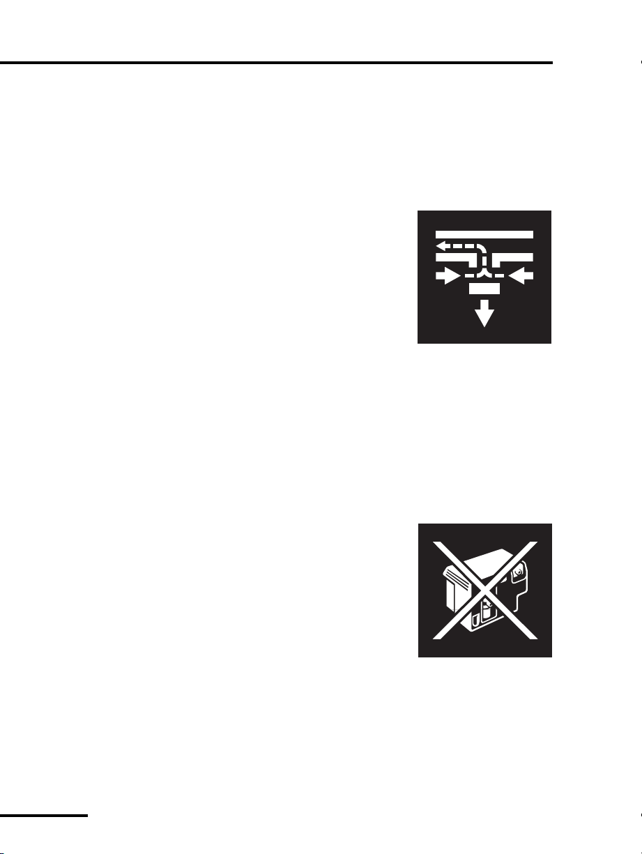
1.1.7 Ventilator emergency states
Emergency states include
ventilator inoperative
and
safety valve open
(SVO)
. When a
ventilator inoperative
condition occurs, it always
includes the SVO state. A SVO state can also occur independent of
a
ventilator inoperative
condition.
The following describe the two ventilator emergency states:
•
Safety valve open (SVO)
: The ventilator
enters a
SVO
state if both air and
oxygen supplies are lost, or an
occlusion is detected, or the ventilator
enters the
Ventilator Inoperative
condition.
The safety valve open
(SVO)
state allows
the patient to breathe room air
unassisted by the ventilator. The
ventilator remains in the
SVO
state until the condition that
caused the emergency state is corrected.
When the ventilator enters the
SVO
state, the
SVO
indicator
on the front face of the BDU illuminates, and a high-urgency
alarm sounds.
In case of a malfunction that prevents software from opening
the safety valve, there is also an analog circuit that opens the
safety valve if system pressure exceeds 100 to 120 cmH
2
O.
•
Ventilator inoperative
: The ventilator
declares a ventilator inoperative
condition if a hardware failure or
critical software error occurs that could
compromise safe ventilation of the
patient.
When a ventilator inoperative
condition occurs, the ventilator
inoperative indicator on the front face
of the BDU illuminates and the ventilator enters the
SVO
state,
which in turns sounds a high-urgency alarm.
If a ventilator inoperative condition occurs, immediately
remove the ventilator from use until qualified service
personnel evaluate and correct the
Vent Ino p
condition.
Loading...