

Page 1
Puritan-Bennett Corp.
2800 Airwest Blvd.
Plainfield, IN 46168
Customer Service:
1-800-635-5267, press 2
Technical Support:
1-800-255-6774, press 2
TECHNICAL MANUAL
HELiOS™ Liquid Oxygen Reservoirs
(Standard and Universal)
HELiOS™ Liquid Oxygen Portables
Part Number B-701693-00 Rev. C (10/02)
©2002 Puritan-Bennett Corp.
CAUTION: Federal (U.S.A.) laws restricts this
!
device to sale by or on the order of a
physician.
Page 2
LIST OF EFFECTIVE PAGES
This list of effective pages represents manual P/N B-701693-00, Revision C.
Revision Description Date
A Initial Release 05-00
B Page Information Changes 10-01
C Universal Res. & Parts Illus. Changes 10-02
Effective Pages Revision Effective Pages Revision
Title Page C 11-1 A
ii C 11-2, 11-3 B
iii A 12-1, 12-2 A
iv to x C 12-3 to 12-8 C
1-1 to 1-3 C 12-9, 12-10 A
1-4 to 1-12 A 12-11 to 12-25 C
1-13 to 1-19 B 13-1 to 13-8 C
1-20 to 1-22 A
2-1 to 2-4 C
2-5 B
2-6 to 2-8 C
2-9 B
2-10 to 2-17 C
3-1, 3-2 C
3-3 A
3-4 to 3-15 C
4-1 to 4-13 C
5-1 to 5-3 C
6-1, 6-2 A
6-3 to 6-9 C
6-10 A
6-11 to 6-22 C
7-1 to 7-8 C
8-1 A
8-2, 8-3 B
8-4 to 8-6 A
8-7 to 8-12 B
9-1, 9-2 A
9-3 B
9-4 to 9-7 A
9-8 to 9-14 B
10-1 B
10-2 to 10-10 C
10-11 A
NOTE: SI pressure values expressed in manual are referenced to
atmosphere.
HELiOS™, Companion®, and Teleview™ are trademarks of PURITAN-BENNETT CORP.
SNOOP® is a trademark of the SWAGELOK Co.
Teflon® and Krytox® are trademarks of E. I. DUPONT DE NEMOURS & Co.
Kel-F® and Scotch-Brite™ are trademarks of the 3M Co.
Magnehelic® is a trademark of the DWYER INSTRUMENT Co.
QUICK-GRIP® is a trademark of the AMERICAN TOOL Co.
Sporicidin® is a trademark of SPORICIDIN INTERNATIONAL.
ii
B-701693-00 Rev. C
Page 3
DEFINITION OF STATEMENTS
Statements in this manual preceded by the following words are of special
significance:
!
A warning describes conditions that concern your personal
safety and the safety of others. It includes the actions required to
prevent injury. Ignoring warnings can lead to injury or death.
CAUTION: A caution informs you about conditions that may
!
cause possible damage to the equipment or other property, or
situations that may cause reduced or no oxygen flow.
NOTE: Notes provide important information about using the equipment properly.
WARNING
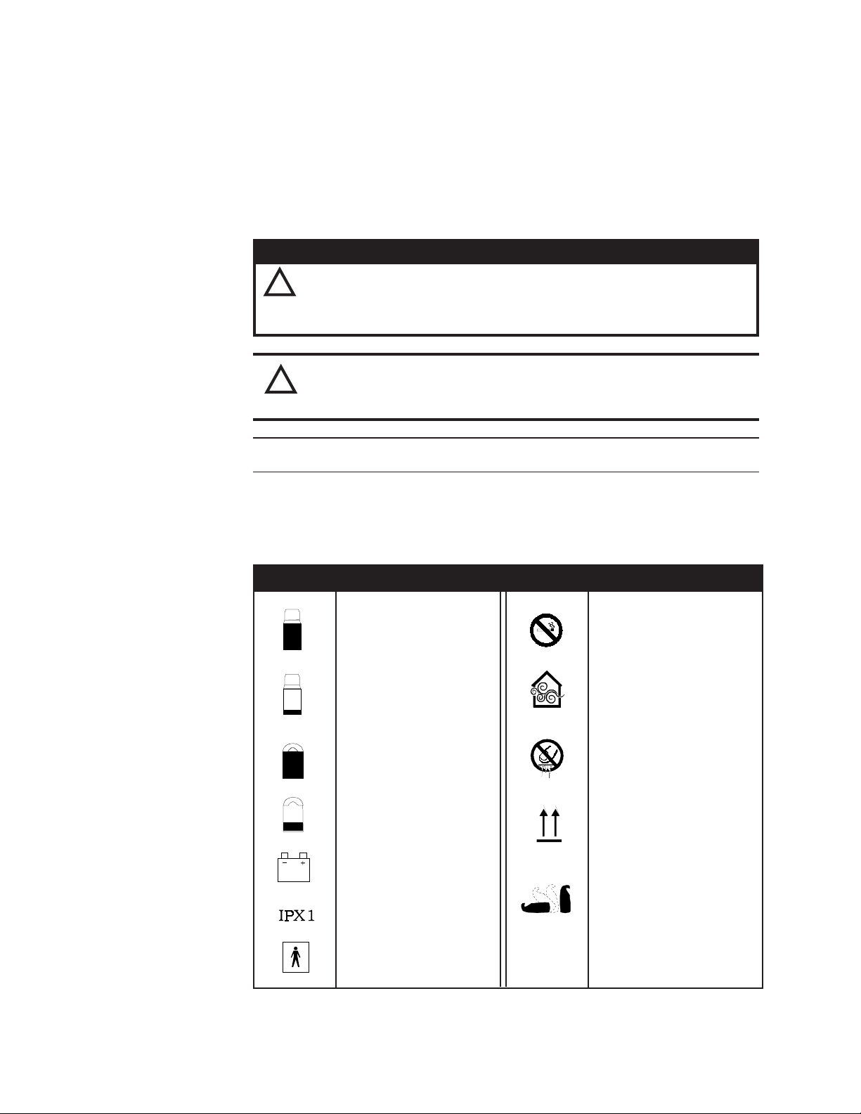
DEFINITION OF PRODUCT SYMBOLS
SYMBOL DEFINITION SYMBOL DEFINITION
Reservoir Full Do not smoke near unit
Reservoir Empty lated at all times
Portable Full parts
Portable Empty Keep unit in upright
Low Battery (9VDC)
Drip Proof position in between
Keep unit well venti-
Do not touch frosted
position
Keep unit upright,
flat on its back, or any
B-701693-00 Rev. A
Type BF
(Electrical Safety)
iii
Page 4
PREFACE
This manual provides the information needed to service the Puritan Bennett HELiOS
Standard Reservoir, Universal Reservoir, and H300 Portable units. Information in the first
section of this manual covers both the Reservoir and the Portable units. Information in
Sections 2 through 7 covers just the Reservoir unit. Information in Sections 8 through 13
covers just the HELiOS 300 Portable unit. This information is intended for use by
technicians or personnel qualified to repair and service medical liquid oxygen equipment. Do not attempt to fill or repair these units until you read and understand the
information in this manual.
The following document contains additional information useful in servicing this equipment:
• HELiOS Oxygen System Operating Instructions: P/N B-701641-00
For product assistance contact: Puritan-Bennett Corp.
2800 Airwest Blvd.
Plainfield, IN 46168
Customer Service:
1-800-635-5267, press 2
Technical Support:
1-800-255-6774, press 2
www.heliosoxygen.com
NOTE: HELiOS Reservoir and Portable units are intended only for the delivery of
medical grade oxygen as prescribed by a physician.
WARNING
Improper usage hazard. Oxygen supplied from this equipment is
!
for supplemental use and is not intended to be life supporting or
life sustaining. This equipment is not intended for use by patients
who would suffer immediate, permanent, or serious health consequences as a result of an interruption in their oxygen supply.
CAUTION: Consistent with the recommendations of the medical
!
community on the use of conserving devices (which includes the
nasal cannula), it is recommended that the HELiOS system be
qualified on patients in the situations it will be used (rest, exercise,
sleep). Differences in nasal cannula design may vary the ability to
trigger a conserving device.
Information contained in this document, including performance specifications, is subject
to change without notice. Puritan-Benett makes no warranty of any kind with regard to the
material in this manual, including, but not limited to, the implied warranties of salability
and fitness for a particular purpose. Puritan-Bennett shall not be liable for errors contained
herein or for incidental or consequential damages in connection with either providing this
manual or the use of material in this manual. HELiOS is a trademark of Puritan-Bennett
Corp. The information contained in this manual is the sole property of Puritan-Bennett
and may not be reproduced without the permission of the company. Copyright© 2002 by
Puritan-Bennett Corp. All rights reserved.
iv
B-701693-00 Rev. C
Page 5

TABLE OF CONTENTS
Section 1 –Introduction to the HELiOS System
1.1 HELiOS System Description ............................................................................ 1-1
1.2 Serial Number Identification ............................................................................ 1-3
1.3 Safety Precautions ........................................................................................... 1-4
1.3.1 Cold Safety .............................................................................................. 1-4
1.3.2 Expansion Safety ..................................................................................... 1-5
1.3.3 Fire Safety ................................................................................................ 1-5
1.4 Liquid Oxygen Saturation Principles................................................................ 1-7
1.5 Pressure Fittings and Connections.................................................................. 1-9
1.5.1 Compression Fitting Makeup .................................................................. 1-9
1.5.2 Compression Fitting Remake ................................................................... 1-10
1.5.3 Compression Fitting Troubleshooting .................................................... 1-10
1.5.4 Tapered Pipe Thread (NPT) Makeup ....................................................... 1-11
1.5.5 Tapered Pipe Thread Troubleshooting .................................................... 1-12
1.5.6 Flexible Tube Barbed Fitting Makeup ...................................................... 1-12
1.5.7 Flexible Tube Removal from Barbed Fitting ............................................. 1-12
1.6 Recommended Tools, Test Equipment, and Service Materials .........................1-12
1.7 Test Equipment Calibration .............................................................................. 1-17
1.8 Accessories ..................................................................................................... 1-18
Section 2 – Reservoir General Information
2.1 Product Description ......................................................................................... 2-1
2.1.1 HELiOS Standard Reservoir ..................................................................... 2-1
2.1.2 HELiOS Universal Reservoir .................................................................... 2-2
2.2 Performance Specifications .............................................................................. 2-3
2.3 Unpacking, Installation, Repacking ................................................................. 2-4
2.3.1 Unpacking ............................................................................................... 2-4
2.3.2 Installation ............................................................................................... 2-4
2.3.3 Repacking for Return ............................................................................... 2-5
2.4 Controls, Indicators, and Connectors ..............................................................2-5
2.4.1 Fill Connector .......................................................................................... 2-5
2.4.2 Release Button ........................................................................................ 2-5
2.4.3 Vent Valve ................................................................................................ 2-6
2.4.4 Pressure Indicator (Standard Reservoir Only) ......................................... 2-6
2.4.5 Contents Indicator ................................................................................... 2-6
2.4.6 Oxygen Outlet .......................................................................................... 2-6
2.4.7 Moisture Container ..................................................................................2-6
2.5 Filling Instructions ........................................................................................... 2-7
2.5.1 Oxygen Source Requirements .................................................................. 2-7
2.5.2 Transfer Line ........................................................................................... 2-9
2.5.3 Pre-Fill Inspection .................................................................................... 2-10
2.5.4 Filling Procedure ...................................................................................... 2-11
2.5.5 Post-Fill Inspection .................................................................................. 2-14
2.5.6 Checking Saturation Pressure .................................................................. 2-14
2.5.7 Resaturating Liquid Oxygen .................................................................... 2-15
2.6 Operating Procedures ...................................................................................... 2-15
2.7 Maintenance .................................................................................................... 2-16
B-701693-00 Rev. C
v
Page 6

3 – Reservoir Theory of Operation
3.1 Reservoir Components .................................................................................... 3-1
3.1.1Cryogenic Container ................................................................................. 3-1
3.1.2 Fill Connector/Quick Connect ................................................................. 3-2
3.1.3 Vent Valve ................................................................................................ 3-3
3.1.4 Relief/Economizer Valve ........................................................................... 3-3
3.1.5 Secondary Relief Valve ............................................................................ 3-5
3.1.6 Pressure Regulator (Standard Reservoir Only) ........................................ 3-5
3.1.7 Warming Coil ........................................................................................... 3-6
3.1.8 Oxygen Outlet w/Poppet Valve ................................................................ 3-6
3.1.9 Pressure Indicator (Standard Reservoir Only) ......................................... 3-7
3.1.10 Contents Indicator ................................................................................. 3-7
3.2 Reservoir Operation ......................................................................................... 3-8
3.2.1 Filling the Reservoir ................................................................................. 3-8
3.2.2 Fill Termination ........................................................................................ 3-10
3.2.3 Standby ................................................................................................... 3-11
3.2.4 Gaseous Oxygen Use ...............................................................................3-12
3.2.5 HELiOS Reservoir Operation Over 24 Hours ........................................... 3-14
4 – Reservoir Performance Verification
4.1 Equipment Required ........................................................................................ 4-1
4.2 Leak Tests ........................................................................................................ 4-2
4.2.1 Liquid Leak Detector Test ........................................................................ 4-2
4.2.2 Pressure Hold Test (Alternate Leak Test) ................................................ 4-5
4.3 Gaseous Oxygen Functional Tests .................................................................. 4-6
4.3.1 Primary Relief Valve Test ......................................................................... 4-6
4.3.2 Secondary Relief Valve Test .................................................................... 4-7
4.3.3 Pressure Indicator Test (Standard Reservoir Only) ................................. 4-8
4.3.4 Pressure Regulator Test (Standard Reservoir Only) ................................ 4-8
4.3.5 Flow Restrictor Test ................................................................................. 4-9
4.4 Liquid Oxygen Functional Tests ...................................................................... 4-10
4.4.1 Contents Indicator Test ........................................................................... 4-10
4.4.2 Normal Evaporation Rate (NER) Test ....................................................... 4-11
4.4.3 Economizer Test ....................................................................................... 4-12
5 – Reservoir Troubleshooting
6 – Reservoir Service and Repair
6.1 Emptying a Reservoir Unit ............................................................................... 6-1
6.2 Shroud Assembly ............................................................................................ 6-3
6.2.1 Upper Shroud Removal ............................................................................6-3
6.2.2 Upper Shroud Service .............................................................................. 6-3
6.2.3 Upper Shroud Installation ....................................................................... 6-3
6.2.4 Lower Shroud Removal ............................................................................ 6-3
6.2.5 Lower Shroud Installation ....................................................................... 6-4
6.3 Contents Indicator ........................................................................................... 6-5
vi
B-701693-00 Rev. C
Page 7

6.3.1 Removal ................................................................................................... 6-5
6.3.2 Service ..................................................................................................... 6-6
6.3.3 Installation ............................................................................................... 6-6
6.4 Pressure Indicator (Standard Reservoir Only) ................................................. 6-7
6.4.1 Removal ................................................................................................... 6-7
6.4.2 Service ..................................................................................................... 6-7
6.4.3 Installation ............................................................................................... 6-7
6.5 Fill Connector Release Assembly .................................................................... 6-8
6.5.1 Removal ................................................................................................... 6-8
6.5.2 Installation ............................................................................................... 6-8
6.6 Male Fill Connector ......................................................................................... 6-8
6.6.1 Removal ................................................................................................... 6-8
6.6.2 Inspection ................................................................................................ 6-9
6.6.3 Service ..................................................................................................... 6-9
6.6.4 Disassembly ............................................................................................ 6-9
6.6.5 Reassembly ..............................................................................................6-10
6.6.6 Installation ............................................................................................... 6-10
6.7 Vent Valve .......................................................................................................... 6-11
6.7.1 Removal ................................................................................................... 6-11
6.7.2 Inspection ................................................................................................ 6-11
6.7.3 Service ..................................................................................................... 6-11
6.7.4 Disassembly ............................................................................................ 6-11
6.7.5 Reassembly ..............................................................................................6-12
6.7.6 Installation ............................................................................................... 6-12
6.8 Relief/Economizer (R/E) Valve ............................................................................ 6-13
6.8.1 Removal ................................................................................................... 6-13
6.8.2 Installation ............................................................................................... 6-13
6.8.3 R/E Valve Adjustment .............................................................................. 6-14
6.9 Secondary Relief Valve ...................................................................................... 6-16
6.9.1 Removal ................................................................................................... 6-16
6.9.2 Installation ............................................................................................... 6-16
6.10 Warming Coil ................................................................................................... 6-16
6.10.1 Removal ................................................................................................. 6-16
6.10.2 Installation ............................................................................................. 6-17
6.11 Economizer Tube Assembly ............................................................................ 6-17
6.11.1 Removal ................................................................................................. 6-17
6.11.2 Installation ............................................................................................. 6-18
6.12 Pressure Regulator (Standard Reservoir Only) ................................................ 6-18
6.12.1 Removal ................................................................................................. 6-18
6.12.2 Service ................................................................................................... 6-18
6.12.3 Installation ............................................................................................. 6-18
6.12.4 Adjustment ............................................................................................ 6-19
6.13 Oxygen Outlet Block (Universal Reservoir Only) ............................................ 6-20
6.13.1 Removal ................................................................................................. 6-20
6.13.2 Installation ............................................................................................. 6-20
6.14 Cryogenic Container ........................................................................................ 6-20
6.14.1 Removal ................................................................................................. 6-20
6.14.2 Installation ............................................................................................. 6-21
6.15 Purging the Container Liquid Sense Tube ....................................................... 6-21
B-701693-00 Rev. C
vii
Page 8

7 – Reservoir Illustrated Parts List
Figure 7-1, HELiOS Standard Reservoir ........................................................... 7-3
Figure 7-2, HELiOS Standard Reservoir ........................................................... 7-4
Figure 7-3, HELiOS Standard Reservoir ........................................................... 7-5
Figure 7-4, HELiOS Universal Reservoir .......................................................... 7-6
Figure 7-5, HELiOS Universal Reservoir .......................................................... 7-7
Figure 7-6, HELiOS Universal Reservoir .......................................................... 7-8
8 - HELiOS 300 General Information
8.1 Product Description ......................................................................................... 8-1
8.2 Performance Specifications .............................................................................. 8-2
8.3 Unpacking, Installation, and Repacking .......................................................... 8-3
8.3.1 Unpacking ............................................................................................... 8-3
8.3.2 Installation ............................................................................................... 8-3
8.3.3 Repacking for Return ............................................................................... 8-3
8.4 Controls, Indicators, and Connectors ..............................................................8-4
8.4.1 Fill Connector .......................................................................................... 8-4
8.4.2 Vent Valve ................................................................................................ 8-4
8.4.3 Contents Indicator ................................................................................... 8-4
8.4.4 Demand Flow Control .............................................................................. 8-4
8.4.5 Oxygen Supply Tube Quick Connect ...................................................... 8-4
8.4.6 Oxygen Outlet Connector ........................................................................ 8-5
8.4.7 Sense Connector ..................................................................................... 8-5
8.4.8 Dual-Lumen Cannula ............................................................................... 8-5
8.5 Filling Instructions ........................................................................................... 8-5
8.5.1 Pre-Fill Inspection .................................................................................... 8-6
8.5.2 Filling Procedure ...................................................................................... 8-6
8.5.3 Post-Fill Inspection .................................................................................. 8-9
8.6 Operating Procedures ...................................................................................... 8-9
8.7 Maintenance .................................................................................................... 8-11
viii
9 – HELiOS 300 Theory of Operation
9.1 H-300 Portable Components ............................................................................ 9-1
9.1.1 Cryogenic Container ................................................................................ 9-1
9.1.2 Fill Connector/Quick Connect ................................................................. 9-2
9.1.3 Vent Valve ................................................................................................ 9-3
9.1.4 Relief/Economizer Valve ........................................................................... 9-4
9.1.5 Secondary Relief Valve ............................................................................ 9-5
9.1.6 Warming Coils ......................................................................................... 9-6
9.1.7 Demand Flow Control Valve .................................................................... 9-6
9.1.8 Oxygen Supply Tube Quick Connect and Inline Check Valve ................. 9-7
9.1.9 Contents Indicator ................................................................................... 9-8
9.2 H-300 Portable Operation ................................................................................. 9-9
9.2.1 Filling the HELiOS 300 ............................................................................. 9-9
9.2.2 Fill Termination ........................................................................................ 9-10
9.2.3 Standby ................................................................................................... 9-11
9.2.4 Gaseous Oxygen Use – H-300 Filled with Liquid Oxygen ........................ 9-12
9.2.5 Gaseous Oxygen Use – H-300 Connected to Oxygen Supply Tube ........ 9-14
B-701693-00 Rev. C
Page 9

10 – HELiOS 300 Performance Verification
10.1 Equipment Required ........................................................................................ 10-1
10.2 Leak Tests ........................................................................................................ 10-2
10.2.1 Liquid Leak Detector Test ...................................................................... 10-2
10.2.2 Pressure Hold Test (Alternate Leak Test) .............................................. 10-4
10.3 Gaseous Oxygen Functional Tests .................................................................. 10-4
10.3.1 Primary Relief Valve Test ........................................................................ 10-4
10.3.2 Secondary Relief Valve Test ................................................................... 10-5
10.4 Liquid Oxygen Functional Tests ...................................................................... 10-7
10.4.1 Contents Indicator Test ......................................................................... 10-7
10.4.2 Normal Evaporation Rate (NER) Test ..................................................... 10-8
10.4.3 Economizer Test ..................................................................................... 10-8
10.4.4 Demand Flow Control Valve Test ........................................................... 10-10
11 – HELiOS 300 Troubleshooting
12 – HELiOS 300 Service and Repair
12.1 Emptying an H-300 Unit ................................................................................... 12-1
12.2 Side Covers ...................................................................................................... 12-2
12.2.1 Removal ................................................................................................. 12-3
12.2.2 Disassembly – Front Side Cover ............................................................ 12-3
12.2.3 Reassembly – Front Side Cover ............................................................. 12-3
12.2.4 Disassembly – Rear Side Cover ............................................................. 12-4
12.2.5 Reassembly – Rear Side Cover .............................................................. 12-4
12.2.6 Installation ............................................................................................. 12-5
12.3 Contents Indicator ........................................................................................... 12-5
12.3.1 Removal ................................................................................................. 12-5
12.3.2 Inspection .............................................................................................. 12-5
12.3.3 Disassembly and Reassembly ................................................................ 12-5
12.3.4 Installation ............................................................................................. 12-5
12.4 Female Fill Connector and Tube ...................................................................... 12-5
12.4.1 Removal ................................................................................................. 12-6
12.4.2 Inspection .............................................................................................. 12-7
12.4.3 Service ................................................................................................... 12-7
12.4.4 Disassembly ........................................................................................... 12-7
12.4.5 Reassembly ............................................................................................ 12-9
12.4.6 Installation ............................................................................................. 12-11
12.5 Vent Valve and Tube ........................................................................................ 12-11
12.5.1 Removal ................................................................................................. 12-11
12.5.2 Inspection .............................................................................................. 12-12
12.5.3 Service ................................................................................................... 12-13
12.5.4 Disassembly ........................................................................................... 12-13
12.5.5 Reassembly ............................................................................................ 12-14
12.5.6 Installation ............................................................................................. 12-14
12.6 Relief/Economizer Valve ................................................................................... 12-14
12.6.1 Removal ................................................................................................. 12-15
12.6.2 Installation ............................................................................................. 12-15
12.6.3 R/E Valve Adjustment ............................................................................ 12-16
B-701693-00 Rev. C
ix
Page 10

12.7 Secondary Relief Valve ................................................................................. 12-19
12.7.1 Removal .............................................................................................. 12-19
12.7.2 Installation ......................................................................................... 12-19
12.8 Demand Flow Co ntrol Valve ......................................................................... 12-19
12.8.1 Removal .............................................................................................. 12-19
12.8.2 Service ................................................................................................ 12-20
12.8.3 Installation ......................................................................................... 12-20
12.8.4 Sensitivity Adjustment ...................................................................... 12-20
12.9 Warming Coils .............................................................................................. 12-22
12.9.1 Removal – Liquid Withdrawal Warming Coil ...................................... 12-22
12.9.2 Installation – Liquid Withdrawal Warming Coil .................................. 12-23
12.9.3 Removal – Gas Withdrawal Warming Coil .......................................... 12-23
12.9.4 Installation – Gas Withdrawal Warming Coil ...................................... 12-23
12.10 Oxygen Supply Tube Quick Connect & Inline Check Valve ......................... 12-23
12.10.1 Removal – Quick Connect ................................................................ 12-23
12.10.2 Installation – Quick Connect ............................................................ 12-24
12.10.3 Removal – Inline Check Valve .......................................................... 12-24
12.10.4 Installation – Inline Check Valve ...................................................... 12-24
12.11 Cryogenic Container ...................................................................................... 12-24
12.11.1 Removal ............................................................................................ 12-24
12.11.2 Installation ........................................................................................12-25
13 – HELiOS 300 Illustrated Parts List
Figure 13-1, HELiOS 300 Portable ................................................................. 13-3
Figure 13-2, HELiOS 300 Portable ................................................................. 13-4
Figure 13-3, HELiOS 300 Portable ................................................................. 13-5
Figure 13-4, HELiOS 300 Portable ................................................................. 13-6
Figure 13-5, HELiOS 300 Portable ................................................................. 13-7
Figure 13-6, HELiOS 300 Portable ................................................................. 13-8
Technical Bulletins
x
B-701693-00 Rev. C
Page 11
HELiOS Liquid Oxygen System Technical Manual
INTRODUCTION TO THE HELiOS SYSTEM
WARNING
Read Section 1, and any other applicable section, thoroughly
!
before attempting to service or fill a HELiOS Reservoir or Portable.
Failure to do so may result in injury or death.
The HELiOS is an innovative liquid oxygen system where the Reservoir and Portable unit
provide a new level of performance efficiency for oxygen therapy patients. This section
provides introductory information on the HELiOS liquid oxygen system. It includes a brief
system description; serial number identification; safety precautions; liquid oxygen
saturation fundamentals; pressure fittings and connections information; tool, test
equipment, and service material recommendations; test equipment calibration information;
and accessory information.
The information in this section relates to both the Reservoir and the Portable units.
Sections 2 through Section 7 provide technical and service information that is specific to
the HELiOS Standard Reservoir and Universal Reservoir units. Sections 8 through Section
13 provide technical and service information that is specific to the HELiOS 300 Portable
unit.
Section
1
1.1 HELIOS SYSTEM DESCRIPTION
The HELiOS liquid oxygen system provides 24 hour per day reservoir and portable oxygen
therapy for a typical Chronic Obstructive Pulmonary Disease (COPD) patient. HELiOS
uses oxygen conservation and exclusive “no loss” technology to greatly improve
performance efficiency compared to conventional liquid oxygen systems. The HELiOS
Reservoir unit redefines the evaporative loss characteristics of home liquid oxygen
vessels and has features that enhance the safety and usability of the product. Using the
H300 Portable with a Standard HELiOS Reservoir will typically require less than one liquid
oxygen delivery to the patient per month. The HELiOS Universal Reservoir has many of
the same features as the Standard Reservoir plus it permits filling the H300 Portable as well
as the Puritan Bennett Companion 1000, Companion T, and Companion 500 series portables. The HELiOS 300 Portable unit sets a new standard for size, weight, and range that
surpasses existing cylinder or liquid based portables.
B-701693-00 Rev. C
Introduction to the HELiOS System
- 1-1
Page 12
HELiOS Liquid Oxygen System Technical Manual
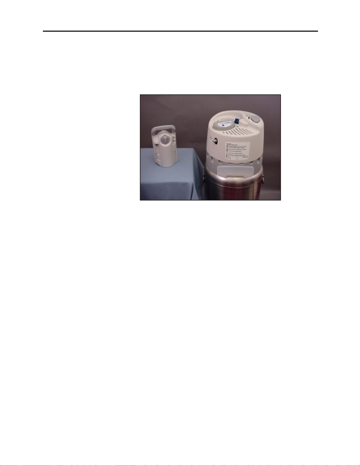
Like today’s liquid oxygen systems, the HELiOS system consists of a Reservoir and a
Portable patient unit (Figure 1-1). However, the system components are capable of
working together rather than separately. The HELiOS 300 Portable fills from the Reservoir
for ambulatory use or connects to the Reservoir with a flexible oxygen supply tube for
home use. This provides the patient with the same familiar interface whether at home or
away.
Figure 1-1: HELiOS Reservoir and Portable
The patient receives oxygen from the H-300 Portable through a dual lumen cannula and a
pneumatic demand flow control system. The H-300 Portable provides 11 different oxygen
flow settings from .12 through 4 . Flow settings from 1 through 4 provide demand flow
oxygen to the patient on each inspiration. No oxygen flows during exhalation. Flow
settings less than 1 provide continuous oxygen flow (L/min) to the patient at the indicated rate. The demand flow control system in a full H-300 Portable can provide a 2 L/min
patient with up to 10 hours of demand flow oxygen. This results in a 4:1 oxygen savings
while still providing adequate oxygen to meet the patient’s needs.
For ambulatory use, the patient fills the H-300 Portable with liquid oxygen from the
Reservoir. When full, it holds slightly less than one pound (454 grams) of liquid oxygen
and weighs a total of 3.6 pounds (1.6 kg). A spring scale type contents indicator shows
the amount of liquid oxygen remaining in the unit.
For oxygen needs in the home, the patient engages the H-300 Portable to a flexible oxygen
supply tube that connects to the oxygen outlet of the Reservoir. The H-300 Portable
provides the patient with the same familiar oxygen delivery interface but the patient now
breathes gaseous oxygen directly from the Reservoir. This makes the H-300 Portable about
one pound (454 grams) lighter since it contains no liquid oxygen. Also, evaporative
oxygen losses from the Reservoir are greatly reduced since the patient breathes the gas
that normally builds pressure and vents through the Reservoir relief valve.
Two HELiOS Reservoir models are available in both 36 liter and 46 liter sizes. The Standard
H-36 and H-46 Reservoirs provide the patient with both a means to fill a HELiOS Portable
with liquid oxygen and a source of regulated 22 psig (152 kPa) gaseous oxygen for
breathing with the H-300 Portable or other external 22 psig (152 kPa) flow-metering device.
The Universal U-36 and U-46 Reservoirs also provide the patient with both a means to fill
a HELiOS Portable with liquid oxygen and a source of 22 psig (152 kPa) gaseous oxygen.
In addition, lower internal pressure in the Universal Reservoir permits the filling of Puritan
1-2 -
Introduction to the HELiOS System
B-701693-00 Rev. C
Page 13
HELiOS Liquid Oxygen System Technical Manual
Bennett Companion portables as well. At the push of a button, an electronic contents
indicator measures and displays the amount of liquid oxygen remaining in the Reservoir.
The H-36 Reservoir, when used with an H-300 Portable, typically yields a four week liquid
oxygen delivery cycle with a 2 L/min patient. The U-36 Reservoir, when used with an H300 Portable, typically yields almost a four week liquid oxygen delivery cycle with a 2 L/
min patient.
The H-46 Reservoir, when used with an H-300 Portable, can yield a six week liquid oxygen
delivery cycle with a 2 L/min patient. The U-46 Reservoir, when used with an H-300
Portable, can yield a five week liquid oxygen delivery cycle with a 2 L/min patient.
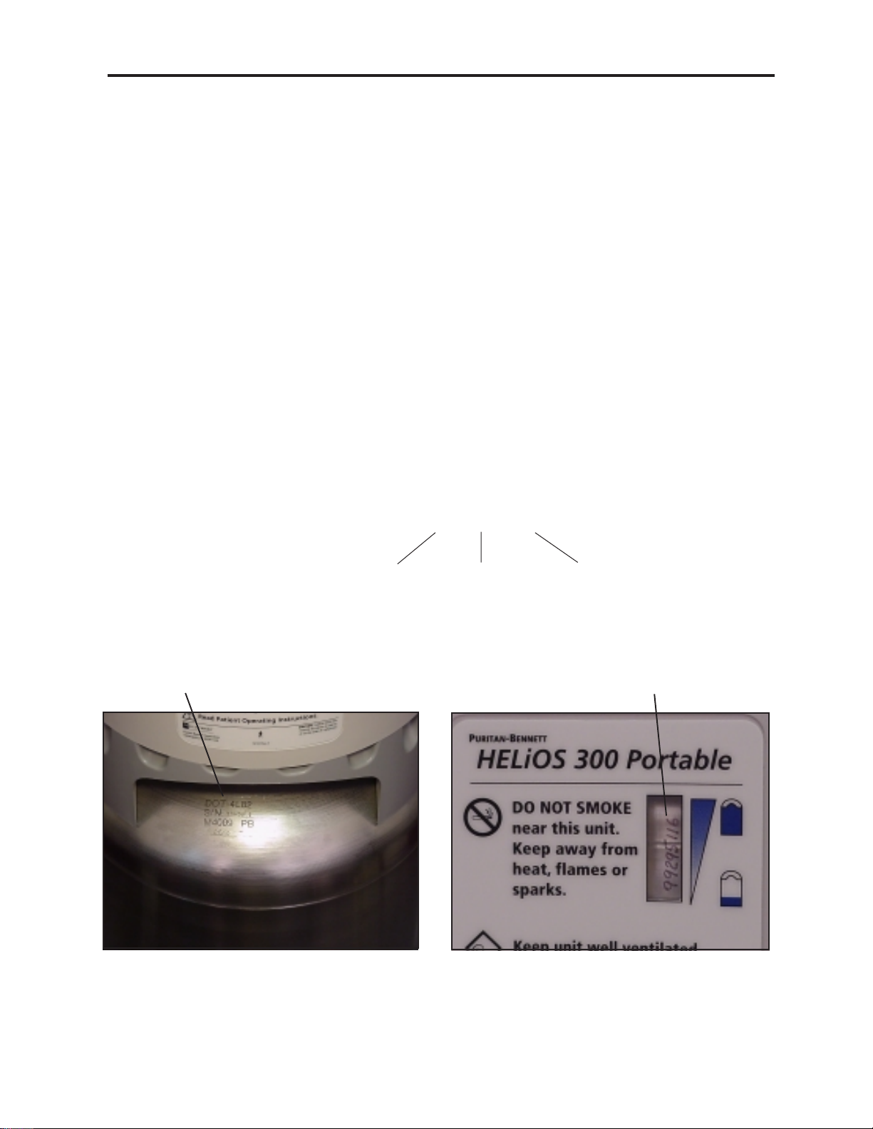
1.2 SERIAL NUMBER IDENTIFICATION
Each HELiOS Reservoir and H-300 Portable are identified by a unique eight-digit serial
number. The number contains the year and calendar day of manufacture, as well as the
unit’s production number for that day (Figure 1-2). The Standard Reservoir serial number
is etched into the upper head of the cryogenic container and is visible when the moisture
container is removed (Figure 1-3). The Universal Reservoir serial number is etched into a
Reservoir handle bracket. The H-300 Portable serial number is etched into the cryogenic
container and is visible through the contents indicator window in the rear side cover
(Figure 1-4).
Serial Number
99 295 116
{
Designates
Year
Figure 1-2: Serial Number Scheme
Designates
Sequential Day of
Year (Jan 1 = 001,
Dec 31 = 365)
{
{
Designates
Number of Specific
Unit Produced
that day
Serial Number
Figure 1-3: Figure 1-4:
Standard Reservoir Serial Number Location H-300 Serial Number Location
B-701693-00 Rev. C
Introduction to the HELiOS System
- 1-3
Page 14
1.3 SAFETY PRECAUTIONS
This section covers precautions and safe practices as they apply to facilities and personnel involved in servicing medical oxygen equipment. These precautions are divided into
three main areas: cold safety, expansion safety, and fire safety. To ensure reliability and
safety, the service techniques, work area, and equipment used in the storage, service, and
handling of this system must be of the highest standard. Refer to the HELiOS Operating
Instructions (B-701641-00) for additional safety precautions regarding the use of this
equipment.
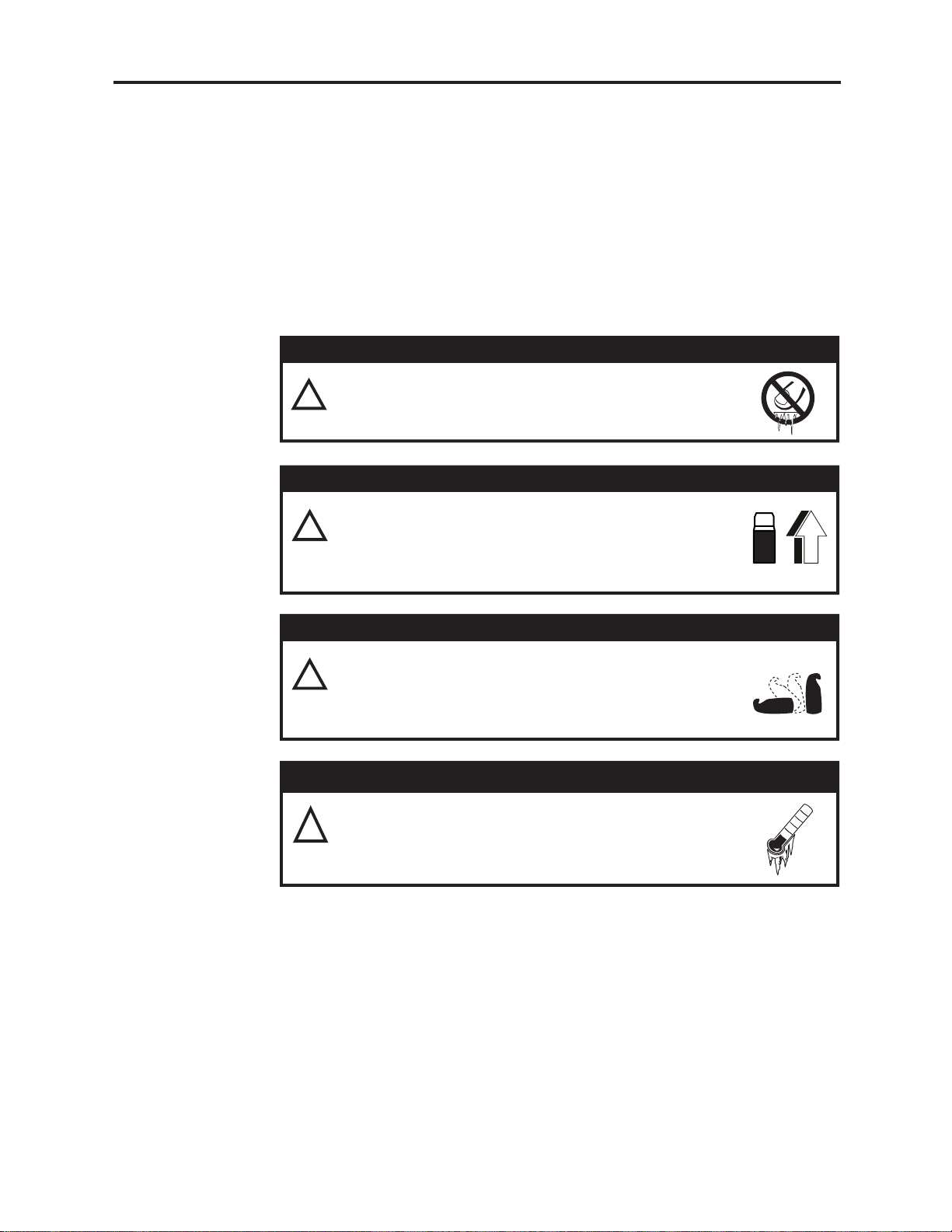
1.3.1 Cold Safety
Extreme cold hazard. Liquid oxygen is extremely cold
!
(-297°F/-183°C) and will freeze skin on contact. Never
touch liquid oxygen or frosted parts.
Extreme cold hazard. Liquid oxygen can spill if the
!
Reservoir is tipped over. Keep the Reservoir upright
at all times. Secure the Reservoir when transporting
to prevent accidental tip-over.
HELiOS Liquid Oxygen System Technical Manual
WARNING
WARNING
WARNING
Extreme cold hazard. Liquid oxygen can spill from the
!
Portable. Always keep the Portable in one of the
following positions; upright, flat on its back or any
position in between.
WARNING
Extreme cold hazard. Forceful discharge of liquid
!
oxygen possible if fill connector freezes open upon
disengagement. Always dry fill connectors with clean,
dry lint free cloth before fill.
Recommended Protective Clothing:
• Heavily insulated gloves (for example, cryogenic or welding gloves). Never use
gloves that are contaminated with grease or oil when working with liquid oxygen.
• Protective face shield and goggles.
• Long sleeve shirt. Wear natural fibers such as cotton or wool. Avoid synthetic
materials such as polyester or rayon.
• Long pants. Never wear pants with cuffs. Liquid oxygen may become trapped and
cause serious burns to skin. Wear natural fibers such as cotton or wool. Avoid
synthetic materials such as polyester or rayon.
• Protective cryogenic or welding apron.
1-4 -
Introduction to the HELiOS System
B-701693-00 Rev. A
Page 15
HELiOS Liquid Oxygen System Technical Manual
Important Facts:
• Direct exposure to liquid oxygen or exposure to its vented gas or components cooled
by liquid oxygen can result in frostbite. If frostbite occurs, seek medical attention
immediately.
1.3.2 Expansion Safety
Explosive hazard. Extreme high pressure can rupture
!
container or plumbing components. Be sure specified
pressure relief devices are present, in the proper
location, and functioning properly.
Important Facts:
• Liquid oxygen at atmospheric pressure expands at a ratio of approximately 860:1 (at 0
psig) when vaporizing into a gas (Figure 1-5). This can occur very rapidly when
exposed to the heat in the atmosphere.
• Ensure that the specified pressure relief devices are present and functioning properly
in any device that will contain liquid oxygen. This includes transfer hose assemblies.
WARNING
LOX
1860
Figure 1-5: Liquid Oxygen Expansion Ratio
1.3.3 Fire Safety
Concentrated Oxygen. Increased risk of fire.
!
• Do not smoke or keep burning tobacco near this equipment.
Death or injury may occur.
• Keep flammable materials away from this equipment. Oils,
grease, including facial creams and petroleum jelly, asphalt, and
synthetic fibers ignite easily and burn rapidly in the presence of concentrated oxygen. If needed, use only specified oxygen compatible
lubricants as directed.
• Keep oxygen equipment away from open flames. Keep Reservoir and Portable units at least five feet away from equipment such as
furnaces, water heaters, and stoves that may contain open flames.
GA S
WARNING
B-701693-00 Rev. A
Introduction to the HELiOS System
- 1-5
Page 16
HELiOS Liquid Oxygen System Technical Manual
WARNING
Concentrated Oxygen. Increased risk of fire.
!
• Keep oxygen equipment away from electrical appliances. Keep
Reservoir and Portable units at least five feet from electrical appliances
that may cause heat or sparks.
• Keep oxygen equipment in a well-ventilated area at all times.
These units periodically release small amounts of oxygen gas that
must be ventilated to prevent buildup. Do not store liquid oxygen
equipment in a car trunk, closet, or other confined area. Do not place
bags, blankets, draperies, or other fabrics over the equipment when it
contains liquid oxygen.
• Do not place the Portable unit under clothing. These units normally
vent oxygen. Placing a Portable unit under clothing may saturate fabrics
with oxygen and cause them to burn rapidly if exposed to sparks or
flame. It may take several hours for oxygen levels in the fabric to return
to normal.
Important Facts:
The possibility of fire exists when the combination of a fuel, source of ignition, and oxygen
is present (Figure 1-6). High concentrations of oxygen (air is approximately 21% oxygen)
greatly enhance the possibility of combustion.
• Obtain all replacement parts for medical oxygen equipment from the manufacturer.
• Before servicing, clean all tools that come into contact with the oxygen system.
• Use only recommended oxygen compatible cleaning and leak detection products.
• Keep the Reservoir upright at all times. Secure liquid oxygen equipment when transporting to prevent accidental tipover and spillage.
• If a liquid oxygen spill occurs indoors, open doors and windows to ventilate the area.
Avoid sources of ignition and do not walk on or roll equipment over the affected area.
• Any clothing or porous material that is splashed with liquid oxygen or otherwise absorbs
high concentrations of oxygen should be removed and aired for at least one hour away
from any source of ignition.
1-6 -
Introduction to the HELiOS System
Figure 1-6: Combustion Triangle
B-701693-00 Rev. A
Page 17
HELiOS Liquid Oxygen System Technical Manual
1.4 LIQUID OXYGEN SATURATION PRINCIPLES
Oxygen, in its normal state, is a colorless, tasteless, and odorless gas that is non-flammable, although it greatly accelerates combustion in high concentrations. It constitutes
about 21% of the Earth’s atmosphere by volume. Oxygen in higher concentrations is
medically beneficial to patients suffering from certain respiratory diseases.
Oxygen, like most gases, will condense into a liquid with an increase in pressure or
decrease in temperature. As a liquid, oxygen is pale blue in color and is about 860 times as
dense as its gaseous form. At atmospheric pressure (14.7 psia), oxygen condenses into its
liquid form at a temperature of about -297°F (-184°C). Liquid oxygen (LOX) is an efficient
form of oxygen to meet a patient’s portable, ambulatory oxygen needs. A volume of liquid
oxygen, when vaporized, yields about 860 volumes of gaseous oxygen (Figure 1-5). As
you can see, a relatively small volume of liquid oxygen provides a much larger volume of
gaseous oxygen for a patient to use.
In medical liquid oxygen systems, liquid oxygen, and the gaseous oxygen resulting from
its vaporization or boiling, is stored under pressure. The elevated pressure, typically 22
psig (152 kPa), enables oxygen to flow to the patient at a selected, prescribed rate. To
sustain this oxygen flow to the patient, the liquid oxygen must be in a state that allows
vaporization to readily occur. In other words, the liquid oxygen must be in a state of
saturation. Let’s take a look at what liquid saturation is all about.
A saturated liquid is one that absorbs the maximum amount of heat possible at a given
pressure without vaporizing into a gas. If additional heat is added, the saturated liquid
begins to vaporize (boil) while remaining at a constant temperature until all of the liquid is
vaporized. A common example of a saturated liquid is water at its boiling point of 212°F
(100°C) at sea level. The constant addition of heat to the boiling water does not cause it to
become hotter, but instead causes part of the liquid water to turn to water vapor
(Figure 1-7).
Figure 1-7: Saturated (Boiling) Water at Sea Level
The saturation (boiling) point of a liquid depends not only on temperature but also on
pressure. If the pressure in a container of saturated liquid increases, the temperature
required for saturation to occur will also increase. This leaves the liquid unsaturated, that
is, capable of accepting more heat before it will boil (Figure 1-8).
B-701693-00 Rev. A
Introduction to the HELiOS System
- 1-7
Page 18
HELiOS Liquid Oxygen System Technical Manual
Figure 1-8: Saturated (Boiling) Water at Higher Pressure
If the pressure in a container of saturated liquid decreases, the temperature required for
saturation to occur will decrease. This leaves the liquid “super saturated” or too warm.
When this occurs, rapid boiling and vaporizing of some of the liquid occurs. The rapid
boiling and evaporation of the liquid dissipates the excessive heat until the remaining
liquid cools down to the new saturation temperature associated with the decreased
pressure (Figure 1-9).
Oxygen, which is normally a gas at atmospheric pressure, changes into liquid form when it
is cooled to about -297°F (-183°C) at atmospheric pressure. It is saturated at this temperature (and pressure) which means it will remain a liquid as long as no additional heat is
added. However, the large quantity of heat present in the atmosphere constantly enters
the liquid oxygen and causes it to boil and vaporize back into a gas. Since it is virtually
impossible to keep all of the heat in the atmosphere from entering the liquid oxygen,
constant boiling and vaporization occurs.
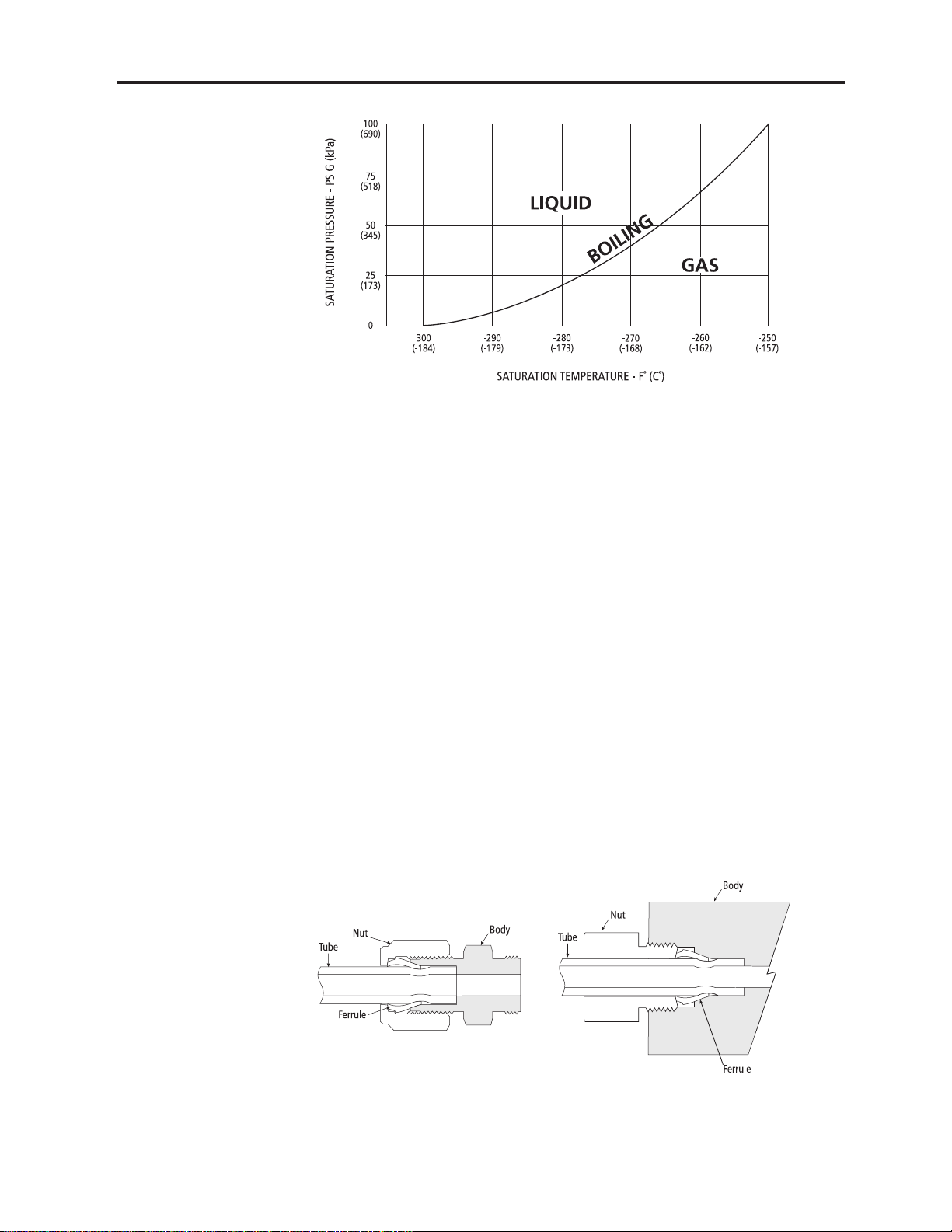
Now when liquid oxygen is placed in a closed container, the vaporizing gas is trapped and
begins to build pressure. As pressure increases above atmospheric pressure, more heat is
needed for boiling to occur at the higher pressure. The heat that is constantly available
from the atmosphere warms the liquid to a higher temperature where boiling again occurs.
The vaporizing gas builds pressure and the process continues. As the pressure on liquid
oxygen builds, the related saturation temperature of the liquid increases proportionally
(Figure 1-10).
1-8 -
Introduction to the HELiOS System
Figure 1-9: Saturated (Boiling) Water at Lower Pressure
B-701693-00 Rev. A
Page 19
HELiOS Liquid Oxygen System Technical Manual
It is important to maintain liquid oxygen saturation (boiling) at the specified operating
pressure of the HELiOS system. As an oxygen flow demand is put on the system, a slight
decrease in pressure occurs due to oxygen withdrawal. The saturated liquid oxygen in the
system vaporizes enough gaseous oxygen to maintain system operating pressure. This
ensures proper oxygen flow to the patient. If the liquid oxygen saturation temperature is
too low, the corresponding lower saturation pressure causes low oxygen flows to the
patient.
Figure 1-10: Liquid Oxygen Saturation Curve
1.5 PRESSURE FITTINGS AND CONNECTIONS
The HELiOS liquid oxygen system uses aluminum tubing compression fittings, tapered
pipe thread (NPT) fittings, and flexible tube barbed fittings. Proper make-up and service of
these pressure fittings is essential to leak-free operation.
1.5.1 Compression Fitting Makeup
The compression fittings used in the HELiOS system consist of a fitting body, tube,
ferrule, and nut (Figure 1-11). These fittings typically connect the aluminum tubing to
other components in the system. In a properly made-up compression fitting, sealing
occurs at two points: between the ferrule and the fitting body; and between the ferrule
and the tube.
Figure 1-11: Compression Fitting
B-701693-00 Rev. A
Introduction to the HELiOS System
- 1-9
Page 20
HELiOS Liquid Oxygen System Technical Manual
Perform the following steps to make up a new compression fitting:
1. Inspect the tube end. The tube end should be cut square and the outside surface of
the tube should be free of scratches or other marks at least one inch (25 mm) back
from the tube end. Lightly buff the tube end with Scotch-Brite or fine emery paper to
remove any surface marks.
2. Insert the tube and make sure it is aligned squarely in the fitting body.
3. Make sure the tube end is bottomed against the tube stop in the fitting body. This is
necessary to prevent movement of the tube while the nut forces the ferrule to grip the
tube and create a seal.
4. Never permit the fitting body to rotate during make-up; use two wrenches. Always
hold the fitting body with a wrench while tightening the tube nut.
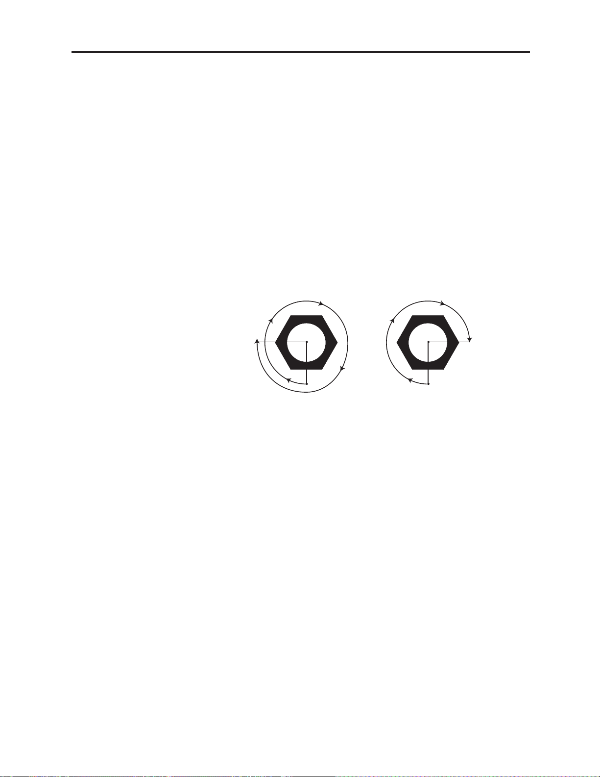
5. Always turn the tube nut the prescribed amount. With the tube against the tube stop
in the fitting body, tighten the tube nut finger-tight (Figure 1-12). For ¼-in. diameter
tubing, tighten the nut an additional 1¼ turns from finger-tight with a wrench. For
1/8-in. diameter tubing, tighten the nut an additional ¾ turn from finger-tight with a
wrench.
1
/
4-in. Tubing
1
/
8-in. Tubing
1
/
1
4 turn from
finger-tight
Figure 1-12: Compression Fitting Makeup
3
/
4 turn from
finger-tight
1.5.2 Compression Fitting Remake
When disassembling a compression fitting, mark the tube nut and the fitting body before
disassembly. To remake the connection, tighten the tube nut until the marks realign. A
slight torque increase indicates the ferrule is being re-sprung into sealing position. After
several remakes, it may become necessary to advance the tube nut slightly past the
original position. This advance need only be 15° to 20° (¼ to 1/3 of a hex flat). In situations where the existing tube with seated ferrule is to be used with a replacement fitting
body, tighten the tube nut until a slight torque increase indicates the ferrule is being resprung into sealing position. Advance the nut an additional 15° to 20°.
1.5.3 Compression Fitting Troubleshooting
Most leaks in compression fittings are the result of improper connections. Typically the
tube is either not aligned squarely in the fitting body before connection or the tube is not
secured against the stop during connection. In addition, overtightening may also result in
a cracked fitting body that will leak.
To check for leaks, pressurize the system and use an oxygen-compatible leak detector
(such as SNOOP) on the fitting. If bubbles form at the back of the nut between the nut and
the tube, you probably did not get a seal between the ferrule and the tube; misalignment
may be the cause. However, check the tube itself for a scratch or seam running along the
tube, allowing a leak to occur.
1-10 -
Introduction to the HELiOS System
B-701693-00 Rev. A
Page 21
HELiOS Liquid Oxygen System Technical Manual
If the leak detector forms bubbles at the front of the nut, between it and the fitting body,
then the leak is probably between the ferrule and the fitting’s tapered seat. Check this area
for imbedded dirt or cracks.
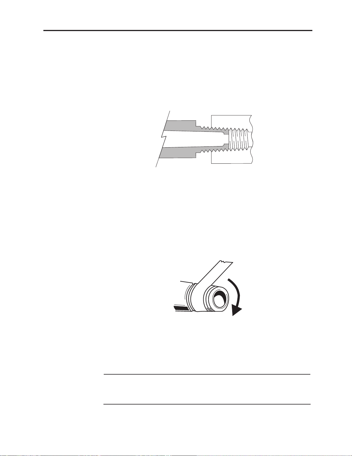
1.5.4 Tapered Pipe Thread (NPT) Makeup
Some components used in the HELiOS system have tapered pipe (NPT) threads (Figure 1-
13). NPT threads create leak-tight connections provided a thread sealant (such as Teflon
tape) is used on the threads.
Figure 1-13: NPT Fittings (National Pipe Tapered)
Perform the following steps when making up a NPT fitting:
1. Remove old thread sealant if present. Use a wire brush to remove sealant or dirt from
male and female threads of NPT fittings. Make sure contaminants do not drop into the
fittings during the cleaning process.
2. Apply thread sealant to the male threads. Apply two to three layers of Teflon tape to
the male threads starting two threads back from the end (Figure 1-14). Wrap the
Teflon tape clockwise (as viewed from thread end of fitting) to prevent unraveling
when installing the fitting.
Figure 1-14: Applying Teflon Tape
3. Assemble the fittings and tighten until snug. Since NPT fittings have tapered threads,
torque requirements increase as the fittings are tightened. Tighten NPT fittings until
you achieve a good seal (usually a minimum of three turns). Do not overtighten NPT
fittings. Overtightening may result in cracked fittings.
Note: Some NPT connections require alignment of one of the fittings in a certain
orientation. Do not back out the fitting if you are unable to achieve the proper
orientation as you tighten the fitting. This will typically result in a leak.
Disassemble and remake the fittings instead.
B-701693-00 Rev. A
Introduction to the HELiOS System
- 1-11
Page 22

HELiOS Liquid Oxygen System Technical Manual
1.5.5 Tapered Pipe Thread Troubleshooting
Leaks at NPT fittings are usually the result of improper application of thread sealant or
loosening of the fittings. To check for leaks, pressurize the system and use an oxygencompatible leak detector (such as SNOOP) on the fitting threads. If bubbles appear,
disassemble the fittings and remake (Section 1.5.4, Tapered Pipe Thread Makeup).
1.5.6 Flexible Tube Barbed Fitting Makeup
Flexible tube barbed fittings are used in the HELiOS system to create leak-tight pressure
connections where flexible tubes connect to components. The outside diameter of the
barb is slightly larger than the inside diameter of the flexible tubing. This creates an
interference fit sufficient to seal and secure the connection.
Perform the following steps to install a flexible tube on a barbed fitting:
1. Inspect the tube end. The tube end should be cut square and should be free of cuts
or tears. If there is an impression of the barb in the tube, cut the end of the tube off (if
the tube length is sufficient) or replace the tube.
2. Where required, install a brass collar on the tube so that the large end of the collar is
toward the barbed fitting.
3. Push the tube squarely onto the barb as far as possible.
4. Push the brass collar (if present) onto the tube end connected to the barbed fitting.
1.5.7 Flexible Tube Removal from Barbed Fitting
Perform the following steps to remove the flexible tube from a
barbed fitting:
1. Use a small flat-blade screwdriver to carefully back the brass collar (when used) off of
the barbed fitting.
2. Work the screwdriver between the end of the tube and the fitting body.
3. Simultaneously pull on the tube and pry the end of the tube back from the barb. Use
care to prevent damage to the barbed fittings.
1.6 RECOMMENDED TOOLS, TEST EQUIPMENT, AND SERVICE MATERIALS
Hand tools, test equipment, and materials used to properly service the HELiOS system
and maintain it in operable condition are listed in Table 1-1. If hand tools, test equipment,
and materials other than those specified in Table 1-1 are used, their functional characteristics such as quality and accuracy must be equal to, or better than, those specified in
the table. Tools, test equipment, and materials should be cleaned for oxygen service.
1-12 -
Introduction to the HELiOS System
B-701693-00 Rev. A
Page 23
HELiOS Liquid Oxygen System Technical Manual
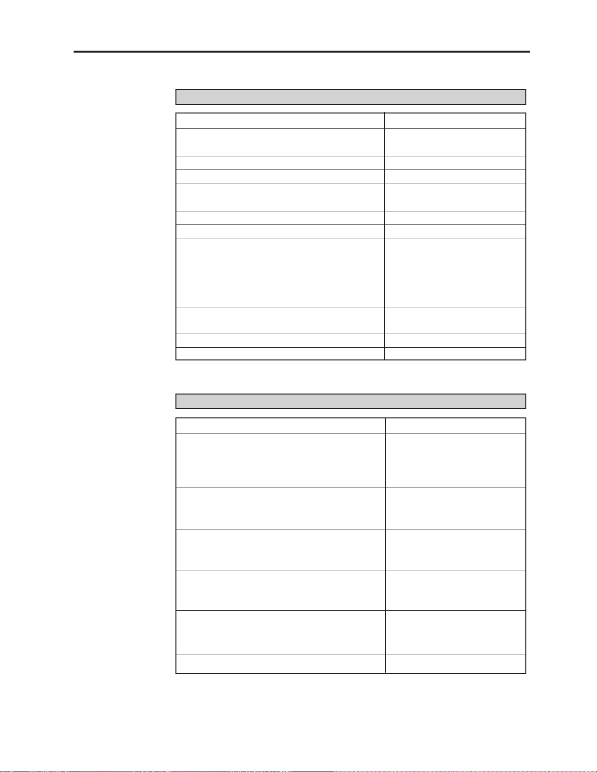
TABLE 1-1. RECOMMENDED TOOLS, TEST EQUIPMENT & SERVICE MATERIALS
Hex Key (Allen) Wrench – 3/32 in., 7/64 in., 5/32 in. Local Source
Open End Wrenches – ¼ in., ½ in., 9/16 in., 5/8 in.,
¾ in., 7/8 in., 1 in. Local Source
Adjustable Wrench – 10 in. Local Source
Pliers – 10 in. arc-joint, needlenose Local Source
Screwdrivers – medium flat blade, small flat blade,
medium Phillips blade, Torx T 10 Local Source
Side Cutters Local Source
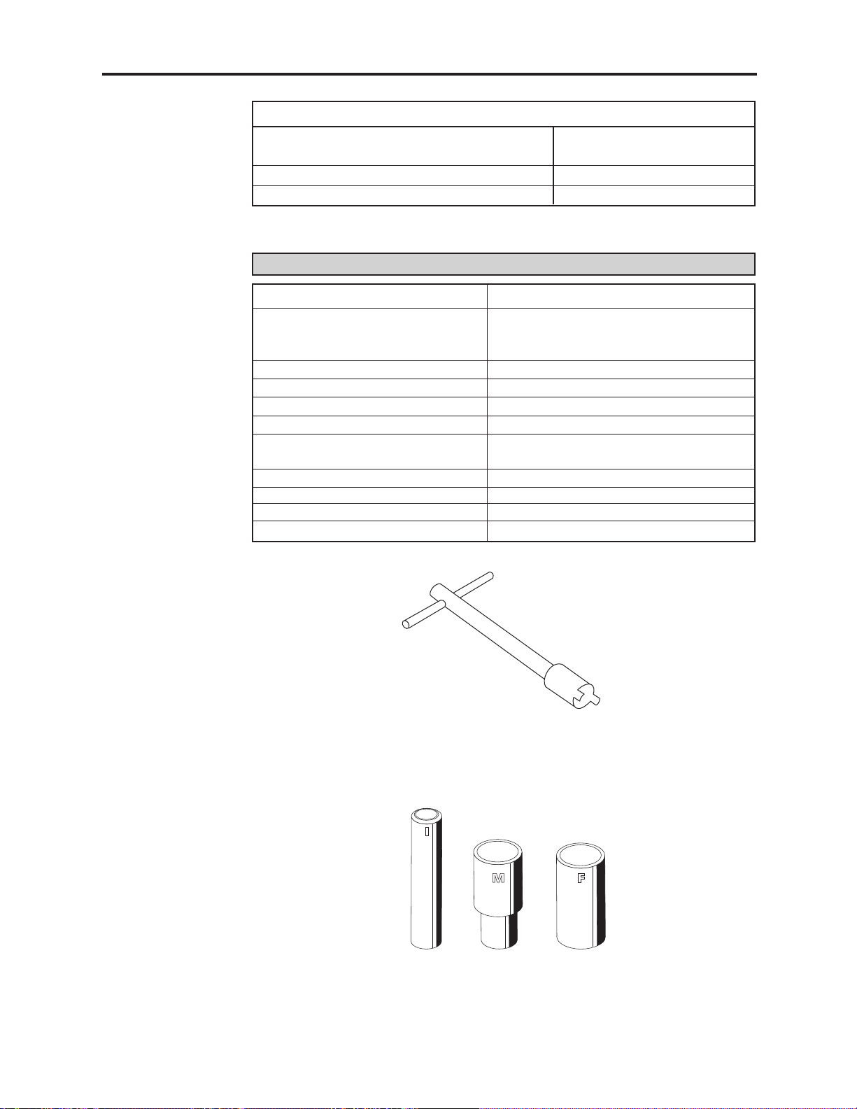
Vent Wrench (Figure 1-15) Puritan-Bennett No. B-775182-00
PB Fill Connector Cartridge Installation
Tools (Figure 1-16)
• Inner Plunger Puritan-Bennett No. B-775392-00
• Male Connector Sleeve Puritan-Bennett No. B-775393-00
• Female Connector Sleeve Puritan-Bennett No. B-775394-00
Micro Bar Clamp American Tool 6-in.
Clamp or Hemostat for 1/16 in. Flexible Tubing Local Source
Dental Pick Local Source
TOOLS
Quick-Grip #53006
TEST EQUIPMENT
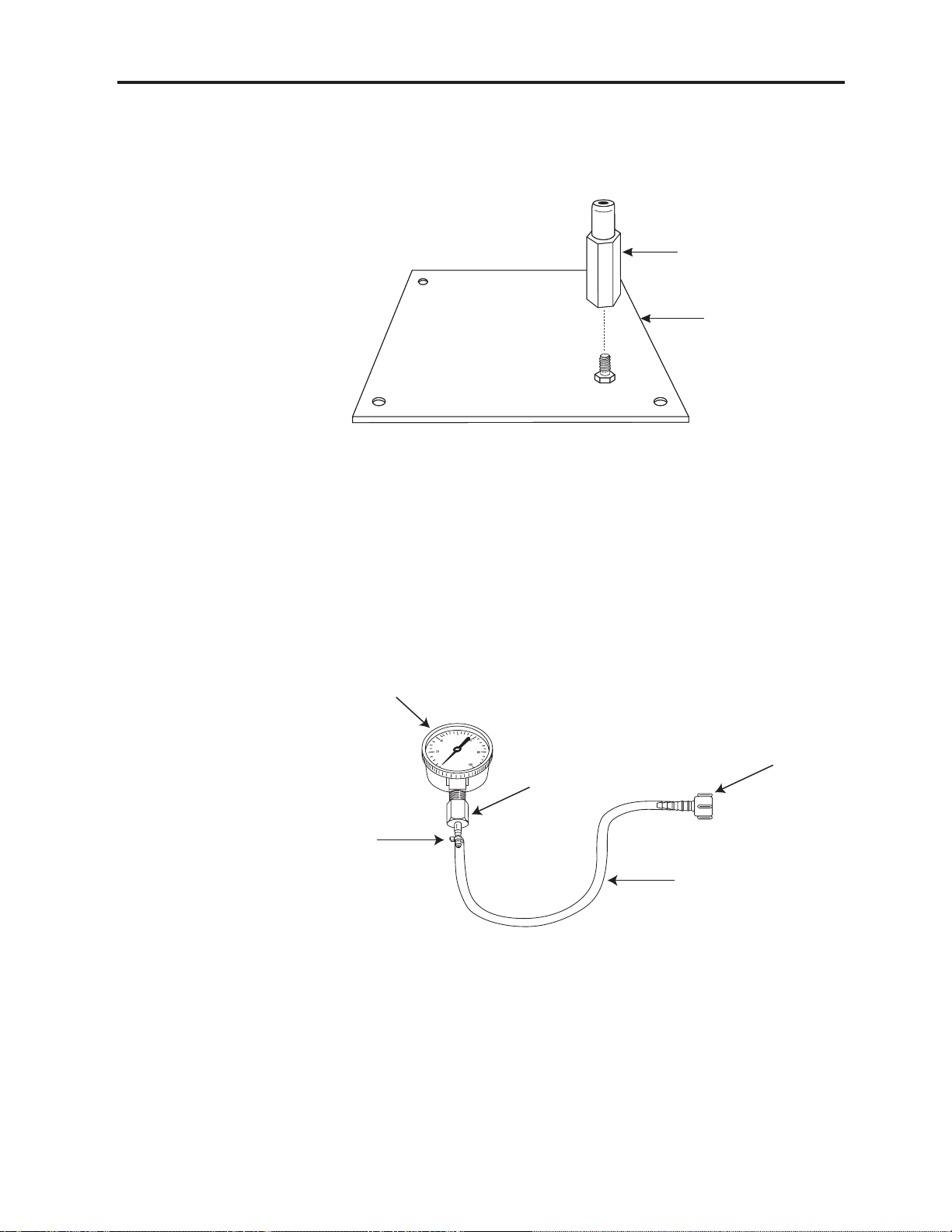
Portable Test Fixture (Figure 1-17) Puritan-Bennett No. B-778202-00
Test Pressure Gauge w/Tubing Adapter –
0-100 psig/0-690 kPa (Figure 1-18) Puritan-Bennett No. B-701732-00
Reservoir Pressurizing Fixture –
0-100 psig/0-690 kPa (Figure 1-19) Puritan-Bennett No. B-701731-00
HELiOS Reservoir Unit w/Liquid Oxygen Puritan-Bennett No. B-701652-00
Saturation at 24 psig (166 kPa) minimum or
(for Portable testing) Puritan-Bennett No. B-701653-00
Adjustable 0-100 psig (0-690 kPa)
gaseous oxygen source Local Source
Oxygen Compatible Leak Detector (Snoop) Puritan-Bennett No. B-775272-00
Calibrated Weight Scale – 0-200 lbs (0-91 kg)
with .02 lb (9.1 g) maximum graduation, accuracy, A&D Engineering Model FW
and repeatability 100-KA1 ( or equivalent)
Calibrated Test Flowmeters Brooks Instrument Division,
• 0-3 L/min oxygen, 1% full scale Emerson Electric Co.,
• 0-40 L/min oxygen, 1% full scale Hatfield, PA
0-10 L/min, 22 psig external flow control valve Puritan-Bennett No. B-701655-00
B-701693-00 Rev. B
Introduction to the HELiOS System
- 1-13
Page 24
HELiOS Liquid Oxygen System Technical Manual
OPTIONAL (PORTABLE ONLY)
Magnehelic Gauge Assembly – 0-25 in. H2O
(Figure 1-20) Puritan-Bennett No. B-778208-00
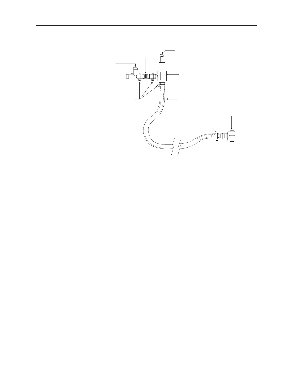
Jet/Venturi Assembly (Figure 1-21) Puritan-Bennett No. B-778210-00
Jet/Venturi Puritan-Bennett No. B-778213-00
SERVICE MATERIALS
Dual Lumen Cannula (Portable) Puritan-Bennett No. B-778057-00 (7 ft./2.1 m)
Oxygen DISS Wye Outlet Adapter w/ Bay Corp., Westlake, OH-Part No. YO-124DV;
Demand Check Valve Outlets Precision Medical, Inc., Northhampton, PA-
Part No. 7211
Size 00 Rubber Stopper VWR Scientific, Batavia, IL-Part No. 59590-084
Tee Connector – 3/16 in. I.D. Tubing Puritan-Bennett No. B-778211-00
3/16 in. (5 mm) I.D. Oxygen Tubing Puritan-Bennett No. B-778214-00 (4 ft./1.2 m)
Tie Wrap, 4-in./10 cm Puritan-Bennett No. B-775091-00
Lubricant - Krytox 240 AC
Fluorinated Grease (DuPont) Puritan-Bennett No. B-775239-00
Isopropyl Alcohol Local Source
Thread Sealant – 3/16 in. Teflon Tape Local Source
Cloth – Lint Free Local Source
HELiOS Oxygen Supply Tube Coupler Puritan-Bennett No. B-701686-00
1-14 -
Introduction to the HELiOS System
Figure 1-15: Vent Wrench
B-775182-00
Figure 1-16: Fill Connector Cartridge Installation Tools
B-775392-00 (I), B-775393-00 (M), B-775394-00 (F)
B-701693-00 Rev. B
Page 25
HELiOS Liquid Oxygen System Technical Manual
Figure 1-17: Portable Test Fixture
B-778202-00
Portable Adapter
P/N B-778203-00
Baseplate
P/N B-778204-00
100 psig Pressure Gauge
P/N B-776004-00
Small Tie Wrap
P/N B-775091-00
Figure 1-18: Test Pressure Gauge w/Tubing Adapter
P/N B-775269-00
B-701732-00
Tubing Barb Adaptor
Disposable Tubing
Barb Adaptor
P/N B-776945-00
Tubing - 3/16 in. I.D. x 4 ft.
(5 mm I.D. x 1.2 m)
P/N B-778214-00
B-701693-00 Rev. B
Introduction to the HELiOS System
- 1-15
Page 26
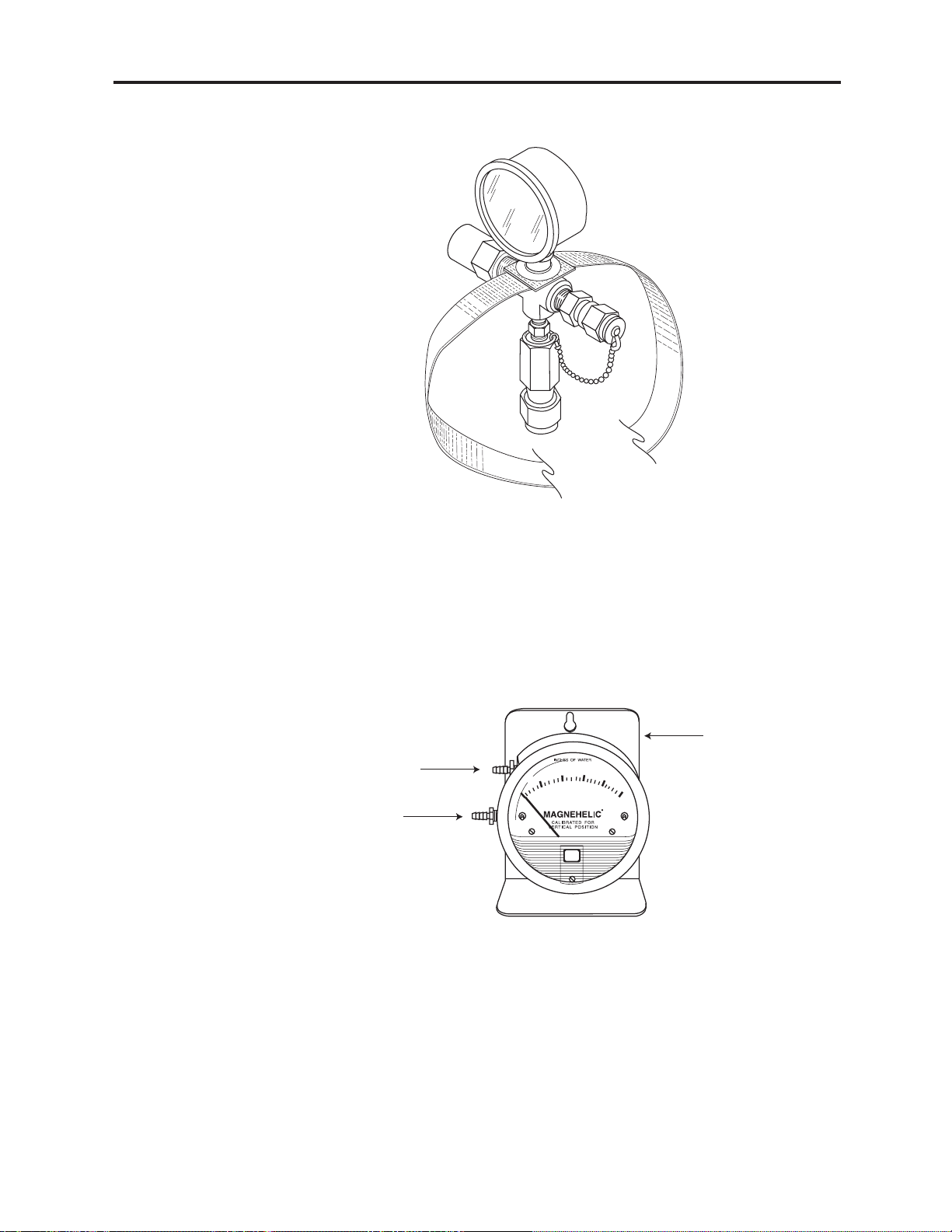
High Pressure Port
Bracket
P/N B-776594-00
Low Pressure Port
HELiOS Liquid Oxygen System Technical Manual
Figure 1-19: Reservoir Pressurizing Fixture
B-701731-00
Figure 1-20: Magnehelic Gauge Assembly
B-778208-00
1-16 -
Introduction to the HELiOS System
B-701693-00 Rev. B
Page 27
HELiOS Liquid Oxygen System Technical Manual
Bleed
Port
P/N B-778211-00
Restrictor
.024 in. (.61 mm)
P/N B-778212-00
Tee
Small- Tie Wrap
P/N B-775091-00
Bleed
Port
Jet/Venturi
P/N B-778213-00
Tubing - 3/16 in. I.D. x 4 ft.
(5 mm I.D. x 1.2 mm)
P/N B-778214-00
Small-Tie Wrap
P/N B-775091-00
Figure 1-21: Jet/Venturi Assembly
B-778210-00
Disposable Tubing
Barb Adapter
P/N B-776945-00
1.7 TEST EQUIPMENT CALIBRATION
Periodically calibrate test equipment (pressure gauges, weight scales, flowmeters, etc.) to
ensure the reliable operation of the HELiOS liquid oxygen system. Use your prior experience to determine calibration frequency for test equipment. Using a default six-month
schedule is typically acceptable; however, check test equipment with a high usage rate
once a month. Once you have begun using the piece of test equipment, you may adjust
the calibration schedule. If, for example, you begin calibrating your test pressure gauge
every six months and it is repeatedly out of calibration when you check it, you should test
calibration more frequently. Eventually, you should determine an interval where your
equipment is in calibration each time you check it.
Before using any piece of test equipment that has been dropped or mishandled, always
perform a calibration check. Test instruments that are used to test the performance of
HELiOS equipment can be sent to an accredited calibration lab for calibration testing.
Another option is to keep a calibrated master test instrument (pressure gauge, flowmeter,
etc.) on site as a reference to check your field test instruments. Look in the telephone
yellow pages under Calibration for the location of an accredited calibration lab. An
example of an accredited calibration lab is:
PTS Calibrations LLC, 5603 W. Raymond St., Suite 1, Indianapolis, IN 46241
Telephone: 317-487-2378
Refer to ISO 10012-1 (Quality Assurance Requirements for Measuring Equipment) for
additional information.
B-701693-00 Rev. B
Introduction to the HELiOS System
- 1-17
Page 28

1.8 ACCESSORIES
Accessories for the HELiOS Reservoir and Portable units are listed in Table 1-2.
Table 1-2
Description Part Number Location
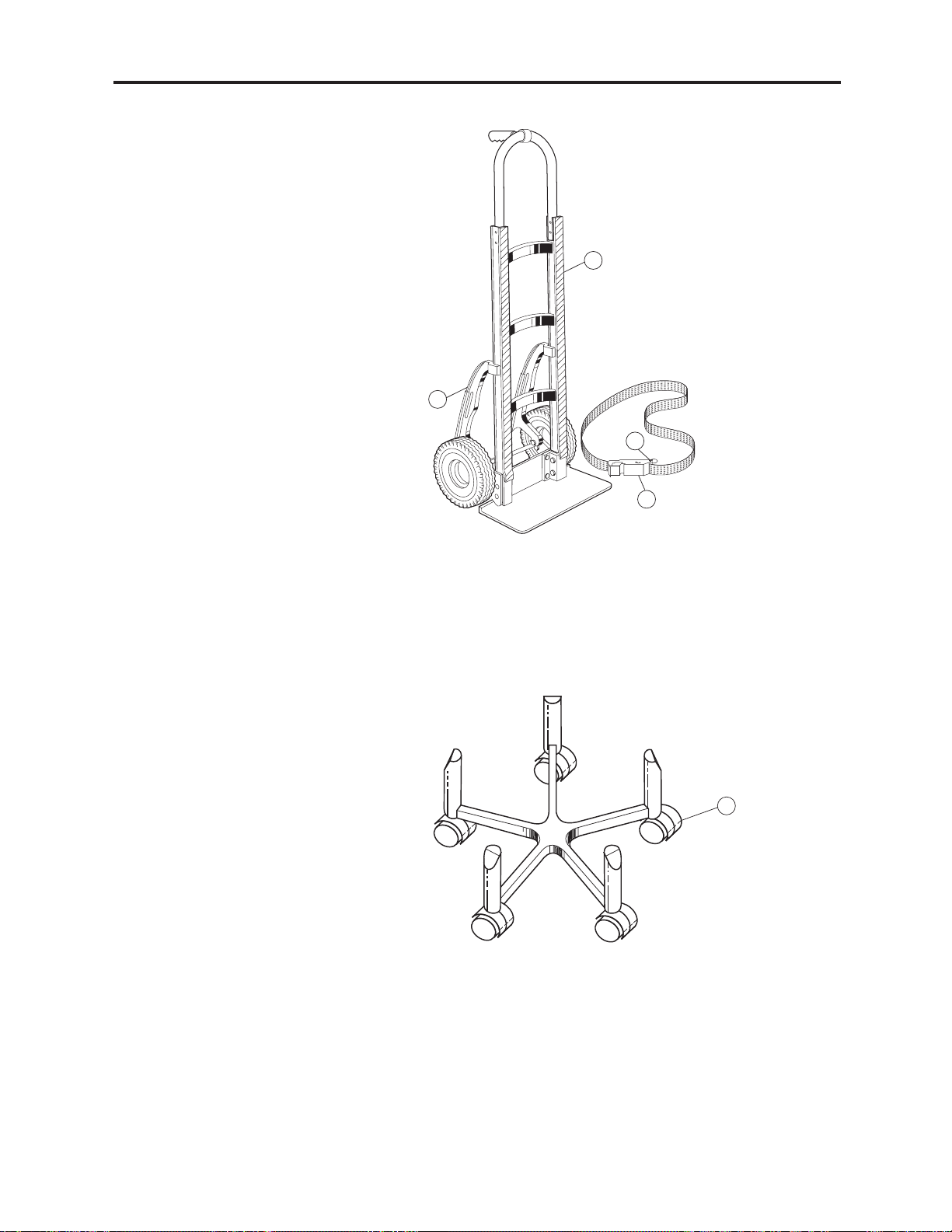
1. Van Companion Assembly (Delivery Cart) B-775462-00 Figure 1-22
2. Roller base Assembly B-701537-00 Figure 1-23
HELiOS Liquid Oxygen System Technical Manual
HELiOS ACCESSORIES
• Strap and Buckle Assembly B-775477-00 Figure 1-22, #1
• Faspin B-775478-00 Figure 1-22, #2
• Pads (2 Required) B-775476-00 Figure 1-22, #3
• Wear Strips (2 Required) B-776169-00 Figure 1-22, #4
• Caster (5 Required) B-701536-00 Figure 1-23, #1
3. Transfer Line Assembly (6 ft./1.8 m) B-775288-00 Figure 1-24
Transfer Line Assembly (10 ft./3 m) B-775289-00 Figure 1-24
• Transfer Hose (6 ft./1.8 m) B-775280-00 Figure 1-24, #1
• Transfer Hose (10 ft./3 m) B-775281-00 Figure 1-24, #1
• Source Adapter Assembly B-775279-00 Figure 1-24, #2
• Relief Valve (150 psi/1035 kPa) B-775273-00 Figure 1-24, #3
• Source Adapter B-775313-00 Figure 1-24, #4
• Fill Adapter Assembly B-775278-00 Figure 1-24, #5
• Fill Adapter B-775312-00 Figure 1-24, #6
• Fill Adapter Seal B-775262-00 Figure 1-24, #7
• Female Fill Connector B-775264-00 Figure 1-24, #8
• Union, 5/8-in. Flare (2/Transfer Line) B-775277-00 Figure 1-24, #9
4. Universal Adapter Kit B-775461-00 Figure 1-25
• Male Flare Adapter B-775342-00 Figure 1-25, #1
• Female Flare Adapter B-775418-00 Figure 1-25, #2
• PB Fill Connector/Tee Assembly B-775276-00 Figure 1-25, #3
1-18 -
Introduction to the HELiOS System
B-701693-00 Rev. B
Page 29

HELiOS Liquid Oxygen System Technical Manual
Table 1-2 (cont.)
Description Part Number Location
5. Shipping Carton, HELiOS 36 B-701690-00 Not Shown
• Corner Post (4 Required) B-702011-00 Not Shown
Shipping Carton, HELiOS 46 B-701691-00 Not Shown
• Corner Post (4 Required) B-702011-00 Not Shown
Shipping Carton, HELiOS 300 Portable B-701688-00 Not Shown
• Insert (1 Required) B-701689-00 Not Shown
6. Dual Lumen Cannula (7 ft./2.1 m) B-778057-00 Figure 1-26
(Sense and delivery in both nostrils)
Dual Lumen Cannula (5 ft./1.5 m) 6-778058-00 Figure 1-26
(Sense and delivery in both nostrils)
HELiOS ACCESSORIES
Dual Lumen Cannula (3 ft./0.9 m) B-701511-00 Figure 1-26
(Sense and delivery in both nostrils)
Dual Lumen Cannula (7 ft./2.1 m) B-701930-00 Figure 1-26
(Sense and delivery in separate nostrils)
Dual Lumen Cannula (4 ft./1.2 m) B-701931-00 Figure 1-26
(Sense and delivery in separate nostrils)
7. Oxygen Supply Tube Assy. (50 ft./15.2 m) B-701656-00 Figure 1-27
8. Oxygen Supply Extension Tube
(50 ft./15.2 m) B-701432-00 Not Shown
9. Reservoir Fill Connector Cover B-777095-00 Figure 1-28
10. H-300 Portable Belt Pack B-701654-00 Not Shown
11. HELiOS Operating Instructions B-701641-00 Not Shown
12. 0-10 L/min Flow Control Valve, B-701655-00 Not Shown
22 PSI (152 kPa)
B-701693-00 Rev. B
Introduction to the HELiOS System
- 1-19
Page 30
HELiOS Liquid Oxygen System Technical Manual
3
4
2
1
Figure 1-22: Van Companion Delivery Cart
Figure 1-23: Roller Base
1
1-20 -
Introduction to the HELiOS System
B-701693-00 Rev. A
Page 31

HELiOS Liquid Oxygen System Technical Manual
2
Figure 1-24: Transfer Line Assembly
NOTE: Install the universal adapter kit on the transfer line assembly to allow the
filling of both Puritan-Bennett and liquid oxygen units with side-fill connectors
with the same transfer line. (Installs between the side-fill adapter and the
transfer hose.)
Figure 1-25: Universal Adapter Kit
B-701693-00 Rev. A
Introduction to the HELiOS System
- 1-21
Page 32

HELiOS Liquid Oxygen System Technical Manual
Figure 1-26: Dual Lumen Cannula
1-22 -
Introduction to the HELiOS System
Figure 1-27: Oxygen Supply Tube
Figure 1-28: Reservoir Fill Connector Cover
B-701693-00 Rev. A
Page 33

HELiOS Liquid Oxygen System Technical Manual
Section
RESERVOIR GENERAL INFORMATION
This section provides general information on the HELiOS Reservoir liquid oxygen system
(Figure 2-1). This information includes a product description; performance specifications;
unpacking, installation, and repacking procedures; description of controls, indicators, and
connectors; filling instructions; operating procedures; and maintenance.
2
2.1 PRODUCT DESCRIPTION
2.1.1 HELiOS Standard Reservoir
The HELiOS Standard Reservoir is part of an innovative liquid oxygen system that
provides 24 hour per day home oxygen therapy with typically less than one liquid oxygen
delivery per month. The Reservoir provides the patient with a source of liquid oxygen to
fill any HELiOS Portable for ambulatory use and a source of gaseous oxygen to power the
HELiOS 300 Portable at home. The unique design of the Reservoir virtually eliminates
oxygen evaporative losses both in standby mode and when supplying gaseous oxygen to
a patient. The Reservoir is available in two models that are nearly identical with the
exception of the liquid oxygen storage capacity. The H-36 holds 36 liters (85 lbs/38.6 kg) of
liquid oxygen while the H-46 holds 46 liters (110 lbs/49.9 kg) of liquid oxygen.
The Reservoir uses the popular Puritan Bennett top fill connector and is compatible with
Puritan Bennett Companion filling equipment (vent wrench, transfer hose assembly,
source tank). The Reservoir requires a minimum 24 psig (166 kPa) saturated liquid oxygen
to operate and may be filled using standard or fast fill techniques. A standard integral
pressure indicator on the unit helps the filling technician maintain proper liquid oxygen
saturation pressure during the fill. An electronic contents indicator uses reliable, differential pressure based level sensing technology to provide accurate and easy to read liquid
oxygen contents indication. The 9-volt battery powered contents indicator incorporates
H-46, U-46
Figure 2-1: HELiOS Reservoir Units
H-36, U-36
B-701693-00 Rev. C
Reservoir General Information
- 2-1
Page 34

HELiOS Liquid Oxygen System Technical Manual
high visibility LEDs for indicating liquid oxygen contents. LEDs also warn of low battery
and low contents conditions.
The Reservoir provides 22 psig (152 kPa) gaseous oxygen at up to 10 L/min continuous
flow through a Diameter Index Safety System (DISS) connection. Oxygen outlet pressure
is regulated at 22 psig (152 kPa) since the unique design of the Reservoir allows internal
pressure to climb as high as 45 psig (311 kPa) in standby. A flexible oxygen supply tube,
attached to the outlet connector, provides gaseous oxygen to power the H-300 Portable.
To fill a HELiOS Portable with liquid oxygen, the patient merely engages the quick connect
couplings on the Portable and Reservoir. The patient then opens the Portable vent valve
to begin filling and closes the vent valve a short time later to terminate the fill. Reservoir
pressure transfers slightly less than one pound of liquid oxygen into an H-300 Portable.
Depressing a release button disengages the Portable from the Reservoir. Due to different
operational specifications, Puritan Bennett Companion system portables cannot be filled
from the HELiOS Standard Reservoir.
For a more technical description of how the Reservoir operates, refer to Section 3, Theory
of Operation.
2.1.2 HELiOS Universal Reservoir
The HELiOS Universal Reservoir retains many of the features of the Standard Reservoir
while being compatible with Companion portable units. The Reservoir provides the patient
with a source of liquid oxygen to fill any Companion portable or H300 Portable for
ambulatory use and provides a source of gaseous oxygen to power the HELiOS 300
Portable at home. The unique design of the Reservoir minimizes oxygen evaporative
losses both in standby mode and when supplying gaseous oxygen to a patient. The
Reservoir is available in two models that are nearly identical with the exception of the
liquid oxygen storage capacity. The U-36 holds 36 liters (85 lbs/38.6 kg) of liquid oxygen
while the U-46 holds 46 liters (110 lbs/49.9 kg) of liquid oxygen.
The Reservoir uses the popular Puritan Bennett top fill connector and is compatible with
Puritan Bennett Companion filling equipment (vent wrench, transfer hose assembly,
source tank) and Companion portables. The Reservoir requires a minimum 22 psig (152
kPa) saturated liquid oxygen to operate and may be filled using standard or fast fill
techniques. An electronic contents indicator uses reliable, differential pressure based
level sensing technology to provide accurate and easy to read liquid oxygen contents
indication. The 9-volt battery powered contents indicator incorporates high visibility
LEDs for indicating liquid oxygen contents. LEDs also warn of low battery and low
contents conditions.
The Reservoir provides 22 psig (152 kPa) gaseous oxygen at up to 10 L/min continuous
flow through a Diameter Index Safety System (DISS) connection. Unlike the Standard
Reservoir, the Universal Reservoir oxygen outlet pressure is maintained at 22 psig (152
kPa) when a flow is delivered but climbs to 26 psig (179 kPa) when in standby mode. A
flexible oxygen supply tube, attached to the outlet connector, provides gaseous oxygen to
power the H-300 Portable. To fill a HELiOS or Companion portable with liquid oxygen, the
patient merely engages the quick connect couplings on the portable and Reservoir. The
patient then opens the portable vent valve to begin filling and closes the vent valve a
short time later to terminate the fill. Depressing a release button disengages the portable
from the Reservoir.
For a more technical description of how the Reservoir operates, refer to Section 3, Theory
of Operation.
2-2 -
Reservoir General Information
B-701693-00 Rev. C
Page 35

HELiOS Liquid Oxygen System Technical Manual
2.2 PERFORMANCE SPECIFICATIONS
The HELiOS Reservoir performance specifications are listed below in Table 2-1.
TABLE 2-1
SNOITACIFICEPSRIOVRESERSOiLEH
LEDOM*63-H*64-H*63-U*64-U
diuqiLfoemuloV
)lacipyt(negyxO
3
tf72.1/sretil63
3
tf26.1/sretil64
3
tf72.1/sretil63
3
tf26.1/sretil64
diuqiLfothgieW
661(gisp42tanegyxO
noitarutaS)aPk
gk6.83/sbl58gk9.94/sbl011gk6.83/sbl58gk9.94/sbl011
)lacipyt(
negyxOsuoesaG
.mta1tatnelaviuqE
3
tf7201/sretil960,92
3
tf8231/sretil916,73
3
tf7201/sretil960,92
3
tf8231/sretil916,73
F°07dna
thgieH
retemaiD
thgieWytpmE
thgieWlluF
erusserPteltuO
erusserPrezimonocE
evlaVfeileRyramirP
erusserP
evlaVfeileRyradnoceS
erusserP
mc1.58/.ni5.33mc3.59/.ni5.73mc1.58/.ni5.33mc3.59/.ni5.73
mc1.93/.ni4.51mc1.93/.ni4.51mc1.93/.ni4.51mc1.93/.ni4.51
gk0.42/sbl35gk2.72/sbl06gk0.42/sbl35gk2.72/sbl06
gk6.26/sbl831gk1.77/sbl071gk6.26/sbl831gk1.77/sbl071
lanimoNaPk251/gisp22
5.32-5.02egnaRelbatpeccA(
)aPk261-141/gisp
lanimoNaPk681/gisp72
0.03-0.42egnaRelbatpeccA(
)aPk702-661/gisp
lanimoNaPk113/gisp54
egnaRelbatpeccA(
)aPk133-092/gisp84-24
lanimoNaPk384/gisp07
egnaRelbatpeccA(
)aPk815-944/gisp57-56
lanimoNaPk251/gisp22
5.32-5.02egnaRelbatpeccA(
)aPk261-141/gisp
lanimoNaPk681/gisp72
0.03-0.42egnaRelbatpeccA(
)aPk702-661/gisp
lanimoNaPk113/gisp54
egnaRelbatpeccA(
)aPk133-092/gisp84-24
lanimoNaPk384/gisp07
egnaRelbatpeccA(
)aPk815-944/gisp57-56
lanimoNaPk251/gisp22
5.32-5.02egnaRelbatpeccA(
)aPk261-141/gisp
lanimoNaPk251/gisp22
5.32-5.02egnaRelbatpeccA(
)aPk261-141/gisp
lanimoNaPk971/gisp62
egnaRelbatpeccA(
)aPk391-661/gisp82-42
lanimoNaPk702/gisp03
egnaRelbatpeccA(
)aPk552-371/gisp73-52
lanimoNaPk251/gisp22
5.32-5.02egnaRelbatpeccA(
)aPk261-141/gisp
lanimoNaPk251/gisp22
5.32-5.02egnaRelbatpeccA(
)aPk261-141/gisp
lanimoNaPk971/gisp62
egnaRelbatpeccA(
)aPk391-661/gisp82-42
lanimoNaPk702/gisp03
egnaRelbatpeccA(
)aPk552-371/gisp73-52
noitaropavElamroN
)REN(etaR
)lacipyt(
)mumixam(
yaDrepgk45.0/sbl2.1
yaDrepgk86.0/sbl5.1
yaDrepgk45.0/sbl2.1
yaDrepgk86.0/sbl5.1
yaDrepgk45.0/sbl2.1
yaDrepgk86.0/sbl5.1
yaDrepgk45.0/sbl2.1
yaDrepgk86.0/sbl5.1
emiTlliF
)euqinhcetdradnats(
)euqinhcetlliftsaf(
.nim6<dloC/.nim7<mraW
.nim3<dloC/.nim4<mraW
.nim7<dloC/.nim8<mraW
.nim4<dloC/.nim5<mraW
.nim6<dloC/.nim7<mraW
.nim3<dloC/.nim4<mraW
.nim7<dloC/.nim8<mraW
.nim4<dloC/.nim5<mraW
wolFteltuOmumixaM
rotacidnIstnetnoC
nim/L01nim/L01nim/L01nim/L01
laitnereffiD,cinortcelE
etomeR/wdesaBerusserP
noitpOnoitacidnI
laitnereffiD,cinortcelE
etomeR/wdesaBerusserP
noitpOnoitacidnI
latnemnorivnE
).pmeTgnitarepO(
).pmeTegarotS(
C°04otC°02-
ytidimuhevitaler.xam%59
C°07otC°04-
ytidimuhevitaler.xam%09
C°04otC°02-
ytidimuhevitaler.xam%59
C°07otC°04-
ytidimuhevitaler.xam%09
* Specifications subject to change without notice.
B-701693-00 Rev. C
laitnereffiD,cinortcelE
etomeR/wdesaBerusserP
noitpOnoitacidnI
C°04otC°02-
ytidimuhevitaler.xam%59
C°07otC°04-
ytidimuhevitaler.xam%09
C°04otC°02-
C°07otC°04-
Reservoir General Information
laitnereffiD,cinortcelE
etomeR/wdesaBerusserP
noitpOnoitacidnI
ytidimuhevitaler.xam%59
ytidimuhevitaler.xam%09
- 2-3
Page 36

HELiOS Liquid Oxygen System Technical Manual
2.3 UNPACKING, INSTALLATION, AND REPACKING
Perform the following procedures when unpacking, installing or repacking a HELiOS
Reservoir unit.
2.3.1 Unpacking
1. Examine the shipping carton for damage. If the carton is damaged, or its contents are
suspected of being damaged, photograph the damaged carton before the Reservoir is
unpacked. Contact the carrier to request a damage inspection. Contact the shipping
point immediately.
2. Place the shipping carton on a flat surface with the shipping arrows pointing upwards.
3. Open the top flaps of the shipping carton and remove accessory items.
4. Remove the plastic bag covering the Reservoir and any loose packing inserts.
5. With the assistance of a helper, grasp a handle on the side of the Reservoir. Hold the
carton down with one hand and carefully lift the Reservoir up and out of the carton.
6. Compare the packing list attached to the carton’s exterior with the shipment received.
If any discrepancies exist, contact Puritan-Bennett immediately at 1-800-497-4968.
7. Thoroughly inspect the exterior of the Reservoir for damage (dents, cracks, etc.).
8. Save all packing materials and the shipping carton for reuse.
2.3.2 Installation
Before installing the Reservoir in a patient’s home, read and understand Section 2.4,
Controls, Indicators, and Connectors; Section 2.5, Filling Instructions; and Section 2.6,
Operating Procedures. Perform the following steps upon receipt of shipment:
1. Remove the moisture container and record the Reservoir serial number. Reinstall the
moisture container.
2. Verify the fill connector release button and mechanism move freely.
3. Press the button on the contents indicator. Verify that the yellow low contents LED
lights.
4. Verify that a Reservoir vent wrench is available for filling the unit.
5. Verify receipt of the HELiOS Operating Instructions (P/N B-701641-00).
2-4 -
Reservoir General Information
6. UNIVERSAL RESERVOIR Verify receipt of the HELiOS Universal Reservoir Reference Guide (P/N B-702125-00).
B-701693-00 Rev. C
Page 37

HELiOS Liquid Oxygen System Technical Manual
2.3.3 Repacking for Return
To return a product, contact Puritan-Bennett at 1-800-255-6774 (press 2) and ask to speak
with a Technical Support Representative. A Return Goods Authorization (RGA) number
will be issued to track the product return. Please have available your account number, the
model and serial number of the product, and the reason for returning the product when
you call to request an RGA. Return the unit in its original carton, if possible. If the original
carton is not available, you may purchase a new carton (Section 1.8, Accessories).
Fire hazard and extreme cold hazard. Do not package or
!
ship units that contain liquid or gaseous oxygen. Liquid
oxygen spillage and high oxygen concentrations are
possible. Empty oxygen contents completely before
packaging or shipping units. See Section 6.1, Emptying
a Reservoir Unit.
1. Obtain the proper carton and inserts for the Reservoir you wish to package (Section
1.8, Accessories).
2. Make sure that the carton inserts are properly in place. The Reservoir handles must
engage the inserts.
WARNING
3. With the assistance of a helper, grasp a handle on the side of the Reservoir and
carefully lift the Reservoir up and into the carton. Make sure the inserts snugly
support the Reservoir.
4. Fold down the set of carton top flaps that press against the top of the Reservoir. Fold
down the second set of flaps and insert the locking tabs into the first set of flaps.
5. Secure the carton with packing tape. Double-tape the carton’s bottom seam.
2.4 CONTROLS, INDICATORS, AND CONNECTORS
The controls, indicators, and connectors that are used on the Reservoir unit are shown in
Figure 2-2. Their functions are described below.
2.4.1 Fill Connector
The Reservoir uses the top fill Puritan Bennett fill connector to transfer liquid
oxygen to and from the unit. It is the male half of a cryogenic quick connect
coupling system. A spring loaded poppet automatically opens when the connector is engaged and automatically closes when the connector is disengaged.
2.4.2 Release Button
Pressing the release button on the Reservoir activates the fill connector release
lever mechanism. This disengages either a portable oxygen unit or a liquid
oxygen transfer line from the Reservoir.
B-701693-00 Rev. B
Reservoir General Information
- 2-5
Page 38

HELiOS Liquid Oxygen System Technical Manual
2.4.3 Vent Valve
The vent valve is a quarter-turn ball valve that is accessible with a separate vent wrench
through a hole in the Reservoir upper shroud. The filling technician opens the vent valve
to vent the inner container during the Reservoir unit filling process. The technician closes
the valve upon terminating the filling process.
2.4.4 Pressure Indicator (Standard Reservoir Only)
The pressure indicator displays the status of the pressure inside the Standard Reservoir
unit. A filling technician monitors the pressure indicator to help maintain a minimum 24
psig (166 kPa) liquid oxygen saturation pressure in the Reservoir during a fill. Under
normal operating conditions, the indicator pointer typically indicates a pressure between
27 psig (186 kPa) and 45 psig (311 kPa). The pressure indicator does not indicate the
regulated pressure at the Reservoir oxygen outlet.
2.4.5 Contents Indicator
The contents indicator displays the amount of liquid oxygen in the Reservoir. Depressing
the button on the contents indicator turns on from one to eight green light emitting diodes
(LEDs) that represent the empty to full range of the Reservoir. A yellow “low contents”
LED comes on when about 8.5 lbs (3.9 kg) of liquid oxygen remain. A yellow “low battery”
LED comes on when battery voltage drops below a predetermined level. A 9-volt alkaline
battery powers the contents indicator.
2.4.6 Oxygen Outlet
The Reservoir oxygen outlet provides a source of 22 psig (152 kPa) oxygen at a maximum
flow of 10 L/min. A spring activated poppet in the Diameter Index Safety System (DISS)
oxygen connector stops oxygen flow when there is nothing attached to the connector.
When a HELiOS Portable oxygen supply tube or a flow control device calibrated at 22 psig
(152 kPa) is attached to the outlet, the connector poppet opens to allow oxygen to flow.
2.4.7 Moisture Container
The moisture container is part of the Reservoir shroud assembly that collects condensed
water run-off from the warming coils. The lower shroud channels the water run-off into the
moisture container. The moisture container slides easily out of the lower shroud assembly
to be emptied.
2-6 -
Reservoir General Information
B-701693-00 Rev. C
Page 39

HELiOS Liquid Oxygen System Technical Manual
Pressure Indicator
(Standard Reservoir)
Contents
Indicator
FIGURE 2-2: Controls, Indicators, and Connectors
Vent
Valve
Oxygen
Outlet
Fill
Connector
Release
Button
Moisture
Container
2.5 FILLING INSTRUCTIONS
The Reservoir must be filled with liquid oxygen saturated at 24 psig (166 kPa) to ensure
proper operation. The information in this section will help you fill the Reservoir with liquid
oxygen in a proper, safe, and efficient manner.
2.5.1 Oxygen Source Requirements
The HELiOS Reservoir must be filled with only U.S.P. Medical Oxygen. The liquid
oxygen used for filling the Reservoir must have no moisture content. Liquid oxygen
entering the Reservoir during the filling operation must be saturated at 24 psig (166 kPa)
for proper operation to occur. In order to achieve 24 psig (166 kPa) saturation in the
Reservoir during the fill, the saturation pressure of the liquid oxygen filling source must be
carefully considered. The filling source saturation pressure requirement mainly depends
on the type of filling technique used. The Standard Fill technique requires a liquid
oxygen source saturation pressure of 40-50 psig (276-345 kPa). The Fast Fill filling
technique requires a liquid oxygen source saturation pressure of 24-28 psig (166-193 kPa).
Following is a brief description of each filling technique and corresponding liquid oxygen
source requirement.
Both Reservoir filling techniques use pressure in the source tank as the force to drive the
liquid oxygen into the Reservoir. In order to transfer liquid oxygen from the source tank to
the Reservoir, a pressure differential must exist so that the source tank pressure remains
greater than the Reservoir pressure during the fill. The Standard Fill technique requires
the source saturation pressure to be greater than the saturation pressure needed in the
Reservoir. With the filling source saturated at 40-50 psig (276-345 kPa), the boiling action
of the liquid oxygen maintains the pressure differential as the Reservoir pressure is
lowered by opening its vent valve. The filling technician adjusts the opening of the
B-701693-00 Rev. C
Reservoir General Information
- 2-7
Page 40

HELiOS Liquid Oxygen System Technical Manual
Reservoir vent valve and/or source tank liquid valve to maintain 24 psig (166 kPa) on the
Reservoir pressure gauge (internal gauge on standard Reservoir; external gauge connected to oxygen outlet on Universal Reservoir). However, liquid oxygen saturated at 4050 psig (276-345 kPa) is at a higher temperature than liquid oxygen saturated at 24 psig
(166 kPa) (see Figure 1-10, Liquid Oxygen Saturation Curve). During the fill, liquid oxygen
saturated at 40-50 psig (276-345 kPa) in the source tank boils rapidly to release heat and
cool down to the lower temperature required for 24 psig (166 kPa) saturation in the
Reservoir. The rapid boiling (desaturation) of the liquid oxygen creates a large volume of
gaseous oxygen that is vented out the Reservoir vent valve during the fill. With the
source saturated at 50 psig (345 kPa), a volume of liquid oxygen equal to about 14% of the
liquid oxygen transferred into the Reservoir boils off into gas and is expelled through the
vent valve as a result of the depressurization (Figure 2-3). Consequently, slower fill times
and greater filling losses occur with the Standard Fill technique.
Percent - %
20
15
Liquid Oxygen Vaporized
During Fill as Percent of
10
Liquid Oxygen Transferred
Into Reservoir*
14%
5
0 1020304050607080
*Warm Fill, H-46 Reservoir at 25 PSIG (172.5 kPa) Saturation
(138)
(69)
Saturation Pressure in Source Tank - PSIG (kPa)
(207) (276)
(345)
(414)
(483)
(552)
Figure 2-3: Vapor Release from Depressurized Liquid Oxygen
The Fast Fill technique requires the liquid oxygen saturation pressure in the source tank
to be about 24-28 psig (166-193 kPa), close to the saturation pressure needed in the
Reservoir. With the source saturated at 24-28 psig (166-193 kPa), rapid boiling
(desaturation) of the liquid oxygen is minimal as it moves from the source tank into the
Reservoir during a fill. However, in order to drive the liquid oxygen from the source tank to
the Reservoir, a pressure differential must exist so that the source tank pressure remains
greater than the Reservoir pressure during the fill. Consequently, a source tank equipped
with a pressure building circuit must be used with the Fast Fill technique. By turning on
the pressure building system in the source tank, a small amount of the liquid oxygen in the
tank vaporizes in a heat exchanger and builds pressure above the surface of the liquid
oxygen. This provides the head pressure (40-50 psig/276-345 kPa) needed to drive the
liquid oxygen saturated at 24-28 psig (166-193 kPa) into the Reservoir. While monitoring
the internal pressure gauge (Standard Reservoir) or an external pressure gauge attached to
the oxygen outlet fitting (Universal Reservoir), the filling technician adjusts the opening
of the Reservoir vent valve and/or source tank liquid valve to maintain 24 psig (166 kPa)
saturation in the Reservoir during the fill. Faster fill times and less filling losses are the end
results. The Fast Fill technique requires a source tank that meets the following conditions:
2-8 -
Reservoir General Information
B-701693-00 Rev. C
Page 41

HELiOS Liquid Oxygen System Technical Manual
1. The source tank must be filled with liquid oxygen saturated at 24-28 psig (166-193
kPa).
2. The source tank must be equipped with a 24-28 psig (166-193 kPa) road relief valve, a
40-50 psig (276-345 kPa) pressure building relief valve, and a means to switch between
the two relief valves. The 24-28 psig (166-193 kPa) relief valve maintains saturation
pressure between fills. The 40-50 psig (276-345 kPa) relief valve enables pressure
building to occur during a fill.
3. The source tank must have a pressure building system capable of maintaining 40-50
psig (276-345 kPa) head pressure during each fill.
Since a variety of source tank configurations and filling pressures are possible, contact
Puritan-Bennett Technical Support for advice when considering a liquid oxygen source
and filling technique to best meet your needs.
2.5.2 Transfer Line
The standard Puritan Bennett transfer line assembly (Figure 2-4) is used to transfer liquid
oxygen from the source tank to the Reservoir. The 5/8-in. flared connection on the transfer
line source adapter connects to a mating fitting on the source tank liquid withdrawal valve.
See Section 1-8, Accessories for individual component descriptions.
WARNING w
Explosive hazard. Extreme high pressure can rupture
!
a transfer line. Make sure the specified pressure relief
valve is present, in the proper location, and functioning
properly.
Source
Adapter
150 PSI (1035 kPa)
Relief Valve
Transfer Hose
Puritan-Bennett
Fill Adapter
Figure 2-4: Standard Transfer Line Assembly
B-701693-00 Rev. B
Reservoir General Information
- 2-9
Page 42

HELiOS Liquid Oxygen System Technical Manual
2.5.3 Pre-Fill Inspection
Perform the following procedure to visually inspect the Reservoir and determine its
operational status before filling. Correct observed problems before proceeding to fill the
Reservoir.
1. Ask the patient (where applicable) if there are any questions or concerns regarding
the equipment since your last visit.
2. Visually inspect the Reservoir unit for overall product integrity (for example, cracked
or damaged components).
3. Verify that all labels are present and legible on the unit (Figure 2-5).
4. Verify that no frost or heavy condensation is present on the container below the
shroud and that there is no excessive venting from the relief valve. (Some venting
from the relief valve is normal.)
5. Verify that the liquid oxygen contents level is consistent with the delivery schedule
and expected patient usage.
6. Verify that the fill connector is not worn, leaking, or damaged.
7. Verify that the vent valve stops are not bent or broken.
8. Verify that the contents indicator is operational and at least one green LED or the
yellow low contents LED lights when the button is depressed. Replace the 9-volt
battery if the yellow low battery LED is on.
9. STANDARD RESERVOIR If the unit contains liquid oxygen, verify that the pressure
displayed on the internal pressure indicator is 24-48 psig (166-331 kPa).
UNIVERSAL RESERVOIR If the unit contains liquid oxygen, connect an external
pressure gauge to the oxygen outlet connector and verify that the pressure displayed
on the gauge is 20-28 psig (138-193 kPa).
10. Verify that the moisture container is in place and empty.
P/N B-701529-00
P/N B-701528-00
Figure 2-5: Reservoir Labels
P/N B-701533-00
HELiOS Reservoir
DO NOT SMOKE near this unit. Keep
away from heat, flame or sparks.
Keep unit well ventilated at all times.
Do not touch frosted parts.
Keep unit in upright position.
Read Patient Operating Instructions.
Puritan-Bennett Corporation
Plainfield, IN 46168 USA
701527 Rev. C
P/N B-701527-00
(Standard Reservoir)
HELiOS Universal Reservoir
DO NOT SMOKE near this unit. Keep
away from heat, flame or sparks.
Keep unit well ventilated at all times.
Do not touch frosted parts.
Keep unit in upright position.
Read Patient Operating Instructions.
Puritan-Bennett Corporation
Plainfield, IN 46168 USA
702104 Rev. A
P/N B-702104-00
(Universal Reservoir)
CAUTION: Federal (USA) law
restricts this device to sale by
or on the order of a physician.
CAUTION: Federal (USA) law
restricts this device to sale by
or on the order of a physician.
2-10 -
Reservoir General Information
B-701693-00 Rev. C
Page 43

HELiOS Liquid Oxygen System Technical Manual
2.5.4 Filling Procedure
Perform the following procedure to fill a HELiOS Reservoir with liquid oxygen.
Fire hazard. Liquid oxygen spilled on asphalt or any other
!
combustible surface will increase the possibility of fire if an
ignition source is present. Always fill the unit on a noncombustible surface, such as concrete or a steel drip pan.
Explosive hazard. Extreme high pressure can rupture a
!
transfer line. Make sure the specified pressure relief valve
is present, in the proper location, and functioning properly.
Fire hazard. Liquid oxygen spillage will occur if the Reser-
!
voir is tipped over. Before transporting, secure Reservoir
units containing liquid oxygen in an upright position.
WARNING
WARNING
WARNING
WARNING
Fire hazard. Oxygen can accumulate in a delivery vehicle.
!
Exhaust vent gases to outside of vehicle. (See CGA Safety
Bulletin SB-9.)
1. Wear the proper protective clothing (Safety Precautions, Section 1.3.1).
2. Verify that the liquid oxygen saturation pressure in the source tank is 40-50 psig (276345 kPa) if using the Standard Fill technique. Verify that the liquid oxygen saturation
pressure in the source tank is 24-28 psig (166-193 kPa) if using the Fast Fill technique. Refer to Section 2.5.1, Oxygen Source Requirements for more information on
source tank requirements.
NOTE: If you experience difficulty obtaining properly saturated oxygen, consult the
Technical Service Department (1-800-255-6774, press 2).
3. Attach the 5/8-in. female end of the transfer line source adapter to the liquid withdrawal valve of the source tank. Position the source adapter relief valve straight up.
B-701693-00 Rev. C
Reservoir General Information
- 2-11
Page 44

HELiOS Liquid Oxygen System Technical Manual
4. STANDARD RESERVOIR If the Reservoir contains some liquid oxygen, verify that
the Reservoir internal pressure gauge reads 24-48 psig (166-331 kPa) (Figure 2-6). A
pressure reading outside of this range may indicate a problem. DO NOT attach an
external pressure gauge to the oxygen outlet DISS connector. If the unit is empty,
continue with step 5 without verifying the pressure at this point.
UNIVERSAL RESERVOIR Attach an external pressure gauge (P/N B-701732-00 or
equivalent) to the Reservoir oxygen outlet DISS connector (Figure 2-7). If the
Reservoir contains some liquid oxygen, verify that the external pressure gauge reads
20-28 psig (138-193kPa). A pressure reading outside of this range may indicate a
problem. If the unit is empty, continue with step 5 without verifying the pressure at
this point.
Internal Pressure Gauge
External Pressure Gauge
Figure 2-6: Standard Reservoir Figure 2-7: Universal Reservoir
5. Remove the fill connector cover from the fill connector, if present. (Available as an
accessory; see Section 1.8, Accessories).
6. Check the fill connectors on both the Reservoir unit and the fill adapter to ensure that
they are clean and dry. Wipe the connectors with a clean, lint-free cloth or blow-dry
with gaseous oxygen or nitrogen as needed.
7. Use the vent wrench to open the vent valve on the Reservoir unit by rotating the
wrench a quarter-turn counterclockwise.
NOTE: At this point you may hear a venting noise if the Reservoir unit is pressurized. Allow the Reservoir pressure to vent down as needed to 24 psig (166 kPa)
before engaging the transfer line.
8. Engage the transfer line to the fill connector on the Reservoir unit by aligning the fill
connector on the transfer line directly over the fill connector on the Reservoir. Apply
about 20 lbs (89 n) of downward force.
9. Maintain a downward force on the transfer line fill adapter while slowly opening the
liquid valve on the source tank. At this point a vigorous audible venting noise will
confirm that the filling process has started. Adjust the source tank liquid valve as
needed to keep the pointer on the pressure gauge at 24 psig (166 kPa).
2-12 -
Reservoir General Information
NOTE: It may be necessary to open the source tank liquid valve completely and
throttle the Reservoir vent valve to maintain the proper pressure during the fill.
B-701693-00 Rev. C
Page 45

HELiOS Liquid Oxygen System Technical Manual
10. Close and reopen the vent valve on the Reservoir after 45 to 60 seconds have passed.
This will minimize the possibility of the vent valve freezing in the open position.
NOTE: As the level of liquid oxygen nears the top of the Reservoir inner container,
the sound and appearance of vapors escaping through the vent valve will change.
The vapor will become denser, and as liquid oxygen reaches the vent valve, a
discharge of liquid oxygen will be visible and audible.
Extreme cold hazard. Liquid oxygen discharge from the fill
!
connector can occur. When disconnecting the transfer line,
never stand directly over the Reservoir fill connector. If the
Reservoir fill connector stays open and minor liquid oxygen discharge occurs, carefully re-engage and disengage
the transfer line to help dislodge any ice or other obstruction. If major liquid oxygen discharge (steady stream)
occurs, open the vent valve (if safely possible) to vent
pressure and stop the release of liquid oxygen. Open
windows and doors to ventilate room and do not walk on
areas exposed to liquid oxygen for 60 minutes after frost
disappears.
WARNING
11. When you observe the first steady discharge (about 1-2 seconds) of liquid oxygen
from the vent valve, disconnect the transfer line from the Reservoir by depressing the
portable release button and lifting the fill adapter straight up. Then close the vent
valve by rotating the vent wrench a quarter-turn clockwise. If the Reservoir pressure
begins to climb past 24 psig (166 kPa), open the vent valve for a few seconds to bring
the pressure back down to 24 psig (166 kPa).
CAUTION: If the vent valve freezes in the open position, terminate
!
the fill by disconnecting the transfer line and then allow the vent
valve to warm until it closes easily. If the vent valve remains open
for a period of time, the liquid oxygen in the unit will desaturate to
a pressure lower than required. If this occurs, refer to Section 2.5.6,
Checking Saturation Pressure.
12. Close the source tank liquid valve when the frost melts from the transfer line assembly. Replace the fill connector cover, if present, on the Reservoir unit.
WARNING
Extreme cold hazard. Liquid oxygen discharge from the
!
transfer line relief valve can occur. Closing the source tank
liquid valve before the frost on the transfer line melts may
trap liquid oxygen in the transfer line. This may cause the
relief valve to open forcefully. Never place hands, arms, or
face directly over the relief valve.
B-701693-00 Rev. C
Reservoir General Information
- 2-13
Page 46

HELiOS Liquid Oxygen System Technical Manual
2.5.5 Post-Fill Inspection
Perform the following procedure to inspect the Reservoir and determine its operational
status after filling it with liquid oxygen. Correct observed problems before placing the unit
in service. Refer to Sections 4 and 6 as needed to correct problems.
1. Verify that the Reservoir fill connector poppet is closed and not leaking.
2. Verify that the vent valve is completely closed and not leaking.
3. Verify that the Reservoir pressure is at least 22 psig (152 kPa) within five minutes after
terminating the fill.
4. Verify that there is no frost or heavy condensation on the container below the
shroud.
5. Verify that all green LEDs light when the contents indicator button is depressed.
6. UNIVERSAL RESERVOIR Disconnect the pressure gauge from the Reservoir oxygen
outlet DISS connector.
2.5.6 Checking Saturation Pressure
Perform the following procedure to determine the saturation pressure of the liquid oxygen
in a Reservoir unit. A Reservoir pressure reading may not always be a true indication of
the liquid oxygen saturation pressure.
1. STANDARD RESERVOIR Note the pressure indicated on the Reservoir internal
pressure gauge.
UNIVERSAL RESERVOIR Attach an external pressure gauge (P/N B-701732-00 or
equivalent) to the Reservoir oxygen outlet DISS connector. Note the pressure
indicated on the pressure gauge.
2. Momentarily open the vent valve on the Reservoir and observe the pressure gauge
pointer as it drops.
3. Note the pressure value where the gauge pointer hovers (Figure 2-8) and then close
the vent valve. This is the approximate saturation pressure of the Reservoir. Saturation pressure readings between 24 and 48 psig (166 and 331 kPa) for the Standard
Reservoir and between 20 and 28 psig (138 and 193 kPa) for the Universal Reservoir
are in the acceptable pressure range of the unit.
2-14 -
Reservoir General Information
Figure 2-8: Indicator Needle “Hovering”
B-701693-00 Rev. C
Page 47

HELiOS Liquid Oxygen System Technical Manual
2.5.7 Resaturating Liquid Oxygen
If the HELiOS Reservoir looses its saturation pressure and you correct the cause of this
condition without emptying the liquid oxygen contents, saturation pressure can be
restored by simply allowing the unit to stand in normal room conditions. The entire
volume of liquid will usually regain proper saturation within several days. If, however, this
is not a reasonable option, perform the following procedure:
1. Attach the source adapter of the transfer line assembly to either the gas withdrawal
valve or vent valve of the source tank.
pressure gauge (P/N B-701732-00 or equivalent) to the Reservoir oxygen outlet DISS
connector.
2. Connect the transfer line fill adapter to the Reservoir unit fill connector and depress to
engage the fill connectors.
3. Slowly open the vent valve or gas withdraw valve on the source tank and monitor the
Reservoir pressure gauge. Open the source tank valve just enough to see a slow,
steady rise in the pressure gauge pointer. Be sure to leave the Reservoir vent valve
closed.
4. Observe the reservoir pressure gauge (Standard Reservoir) or external pressure gauge
(Universal Reservoir). When the pressure gauge pointer reaches 24 psig (166 kPa),
close the source tank valve.
For a Universal Reservoir, attach an external
5. Recheck the saturation pressure as described in Section 2.5.6. Repeat the resaturation
procedure, if necessary, until the liquid oxygen is saturated. Be sure to reconnect the
transfer line to the source tank liquid valve after completing this procedure.
2.6 OPERATING PROCEDURES
The patient typically uses the HELiOS Reservoir in two different ways. First, the Reservoir
provides the patient with a liquid oxygen filling source for a portable unit. The Standard
Reservoir will fill only HELiOS portable units. The Universal Reservoir will fill HELiOS
portable units as well as Companion portable units. Second, the Reservoir provides
gaseous oxygen for the patient to breathe when at home. The Reservoir can supply
gaseous oxygen either to the H-300 Portable or to an optional external 22 PSIG (152 kPa)
flow control valve. Procedures for filling a portable from the Reservoir are found in the
Portable Filling Instructions sections of this manual. To operate the Reservoir as a source
of gaseous oxygen to supply the H-300 Portable, perform the following steps:
1. Verify that there is adequate liquid oxygen in the Reservoir to meet patient breathing
needs.
2. Insert the flexible oxygen supply tube connector into the quick connect on the front
of the H-300 and snap it in place (Figure 2-9(a)).
3. Locate the oxygen DISS nut and tailpiece assembly attached to the opposite end of
the flexible oxygen supply tube. Thread the nut and tailpiece assembly onto the
Reservoir oxygen outlet connector until secure (Figure 2-9(b)).
4. Verify that the tube connections are leak tight.
B-701693-00 Rev. C
Reservoir General Information
- 2-15
Page 48

HELiOS Liquid Oxygen System Technical Manual
5. Place one of the tubes from the dual-lumen oxygen cannula on the H-300 Portable
oxygen outlet connector (upper connector). Place the other cannula tube on the
sensor connector (lower connector). Adjust the cannula on the face to receive oxygen
comfortably.
6. Set the H-300 Portable flow control knob to the prescribed oxygen flow setting.
NOTE: For additional information, refer to Section 8, H-300 Portable General
Information.
2.7 MAINTENANCE
The Pre-Fill Inspection and Post-Fill Inspection conducted as part of the Reservoir filling
procedure provide routine assessment of the functional status of the Reservoir. Functional
problems observed during these inspections must be corrected before placing the unit in
service.
Use the information in Table 2-2 as a guide to clean, inspect, and test the Reservoir when
functional problems are observed or as needed.
NOTE: The following cleaning and disinfecting solutions are acceptable for use with
the HELiOS Reservoir:
Cleaning • Sporicidin Disinfectant Solution
Disinfecting • Sporicidin Disinfectant Solution
(a) (b)
Figure 2-9: Flexible Oxygen Supply Tube Connections
• Mild dish washing detergent/warm water solution
• Household Bleach (1:10 dilution with water,
freshly made within 24 hours)
2-16 -
Reservoir General Information
B-701693-00 Rev. C
Page 49

HELiOS Liquid Oxygen System Technical Manual
TABLE 2-2
ITEM ACTION
Cleaning • Remove the upper shroud and clean the interior and
RESERVOIR MAINTENANCE GUIDE
exterior with a mild detergent and water. Wipe dry with
a towel. Use cotton swabs in tight places. Use ScotchBrite pad
lightly
with detergent to remove scuff marks.
• Clean the contents indicator with a towel moistened
with detergent and water. Wipe dry.
• Clean the Reservoir plumbing and lower shroud with
detergent and water. Dry with a towel and oil-free
compressed gas.
NOTE: Make sure that the fill connector and vent valve
shaft are thoroughly dry before proceeding.
• Remove the moisture container and thoroughly clean
and dry it. Verify that the condensate drain hole in the
lower shroud is open.
• Clean the stainless steel container with oil-free cleaner
and Scotch-Brite abrasive pad to remove scuff marks.
Inspection • Inspect the upper and lower shrouds for cracks,
warpage, and discoloration.
• Verify that the warning labels (Figure 2-5) are present
and legible on the upper shroud.
• Verify that the Portable release mechanism moves
freely and is not worn. Verify that the release button is
secure on the lever and is not cracked.
• Verify that the fill connector is not worn or damaged
and that the poppet is not broken.
• Verify that the vent valve shaft pin and valve stops are
not bent or broken.
• Verify that the yellow “low contents” LED lights when
the contents indicator button is depressed (empty unit).
Replace the 9-volt battery if the low battery LED lights.
• Verify that the aluminum tubing is not bent or kinked
and that a uniform air gap exists between each coil.
Testing • Perform Leak Test (Section 4.2).
• Perform Gaseous Oxygen Functional Tests
(Section 4.3).
• Perform Liquid Oxygen Functional Tests (Section 4.4).
B-701693-00 Rev. C
Reservoir General Information
- 2-17
Page 50

HELiOS Liquid Oxygen System Technical Manual
Section
RESERVOIR THEORY OF OPERATION
This section describes the theory of operation for the HELiOS Reservoir liquid oxygen
system. Two HELiOS Reservoir models are available, the Standard Reservoir and the
Universal Reservoir. Each model comes in two sizes, 36 liquid liters and 46 liquid liters. The
H-36 and U-36 models hold 36 liters (85 lbs/38.6 kg) of liquid oxygen while the H-46 and U46 models hold 46 liters (110 lbs/49.9 kg) of liquid oxygen. Information presented in this
section will help you understand how the HELiOS Reservoir system works. Items covered
include functional descriptions of HELiOS Reservoir components and complete HELiOS
Reservoir system operation.
NOTE: Numerical values used in this section are nominal values.
3.1 RESERVOIR COMPONENTS
Following is a brief description of each of the major functional components of the HELiOS
Reservoir unit.
3.1.1 Cryogenic Container Liquid oxygen stored in the HELiOS Reservoir is typically saturated and boiling at a temperature somewhere between about -277°F (-186°C) and -268°F (-167°C). The constant transfer of heat from the atmosphere into the system keeps the liquid oxygen boiling and vaporizing into gas. If the heat flow into the liquid oxygen is not controlled, vaporization occurs too rapidly, and excess oxygen is vented to the atmosphere and wasted. The cryogenic container (Figure 3-1) is designed to minimize the transfer of heat from the atmosphere to the liquid oxygen contents. This is done by slowing the three methods of heat transfer: conduction, convection, and radiation.
3
Liquid Pressure
Sense Tube
Inner Container
Insulation
Molecular Sieve
Figure 3-1: Cryogenic Container
B-701693-00 Rev. C
Neck Tube
Vacuum Plug
Outer Container
Fill Tube
Reservoir Theory of Operation
- 3-1
Page 51

HELiOS Liquid Oxygen System Technical Manual
Conduction is the transfer of heat through a material, such as metal, by collisions of
molecules in the material. Molecules at the hotter end of the material are moving faster
than molecules at the cooler end. Heat is transferred from molecule to molecule as fast
moving molecules run into the slower moving ones. Conductive heat transfer is kept to a
minimum by placing the liquid oxygen in a stainless steel inner container suspended
within a stainless steel outer container. This reduces the number of places where the
warmer outer container comes into physical contact with the colder inner container that
holds the liquid oxygen.
Convection is the transfer of heat by motion of a heated fluid (gas or liquid) from one
place to another. When a layer of gas, for example, is heated, it tends to rise above or
move away from the surrounding gas. Cooler gas moves in to take its place. This gas is
heated, rises and moves away. Heat is transferred by circulation of the heated gas. To
minimize convective heat transfer between the warm outer container and cold inner
container, air is removed from the sealed space between the outer and inner containers. A
vacuum applied through the evacuation port removes most of the gas molecules in this
space. Since no vacuum created on earth is perfect, a molecular sieve material is placed in
the vacuum space against the inner container. When liquid oxygen in the inner container
cools the molecular sieve to cryogenic temperatures, remaining gas molecules are removed
from the vacuum space by adsorption into the sieve. This substantially improves the
vacuum and reduces heat transfer by convection.
Radiation is the transfer of energy at the speed of light in the electromagnetic spectrum.
Warm bodies emit infrared radiation, a form of light. Like visible light, mirrors and shiny
surfaces reflect infrared. When infrared is absorbed, it creates a rise in temperature of the
absorbing material. To minimize energy transfer by radiation, the inner container is orbital
wrapped with multiple, alternating layers of aluminum foil and fiberglass paper. This
insulation wrap reflects back radiant energy from the outer container and reduces radiant
energy absorption by the liquid oxygen.
3.1.2 Fill Connector/Quick Connect
The fill connector/quick connect (Figure 3-2) on the HELiOS Reservoir is the male half of a
fluid coupling system. It mates with the female fill connector on a HELiOS Portable
(Standard Reservoir) or HELiOS and Companion portables (Universal Reservoir). The
Reservoir fill connector allows liquid oxygen to transfer from the Reservoir unit into the
Portable. It also allows transfer of liquid oxygen from a fill source through a transfer line
into the Reservoir. Within the male fill connector is a cartridge assembly made up of a
spring and a poppet. When the fill connector is disengaged, the spring holds the poppet
closed and maintains a leak-tight seal. When the female fill connector engages the male fill
connector, both connector poppets move back off of their respective seats (Figure 3-3).
This creates an open path for liquid oxygen to transfer through the connection. A lip seal
in the female fill connector assembly prevents leakage between the female and male fill
connectors during liquid oxygen transfer.
Cartridge
Assembly
3-2 -
Reservoir Theory of Operation
B-701693-00 Rev. C
Page 52

HELiOS Liquid Oxygen System Technical Manual
Figure 3-3: Male/Female Fill Connectors Fully Engaged
3.1.3 Vent Valve
The vent valve (Figure 3-4) is a quarter turn ball valve that vents the HELiOS Reservoir
inner container to atmosphere. Venting of the inner container is required to fill the Reservoir with liquid oxygen. A vent valve wrench engages the valve shaft to activate the valve.
When the valve is closed, the hole through the valve ball is at 90° to the inlet and outlet
ports of the valve. Flow through the valve is stopped. When the valve shaft is rotated 90°
with the vent wrench, the hole in the valve ball lines up with the inlet and outlet ports.
Flow through the valve occurs. The fill technician can partially close the vent valve to
restrict maximum vent flow and help maintain adequate pressure in the Reservoir during
filling.
Figure 3-2: Male Fill Connector
Figure 3-4: Vent Valve
3.1.4 Relief/Economizer Valve
The relief/economizer valve is a pressure-regulating device that combines the function of a
primary relief valve and an economizer valve into one component (Figure 3-5).
The primary relief valve establishes the system pressure of the HELiOS Reservoir unit
when there is no oxygen flow through the oxygen outlet (“Standby” condition). It
contains a spring-loaded diaphragm that, in its normal state, seals a port that is vented to
atmosphere. System pressure acts on one side of the diaphragm. When this pressure
overcomes the force created by the spring and atmospheric pressure acting on the
opposite side, the diaphragm lifts off of the port. This allows gas in the space above the
liquid oxygen (headspace) to vent to atmosphere. The venting gas lowers the system
B-701693-00 Rev. A
Reservoir Theory of Operation
- 3-3
Page 53

HELiOS Liquid Oxygen System Technical Manual
pressure until equilibrium is established between the opening and closing forces on the
diaphragm. The rate at which gas is vented out the primary relief valve is determined by
the normal evaporation rate (NER) of the system. The Standard Reservoir maintains a
primary relief valve nominal pressure of 45 psig (311 kPa) when in the Standby condition.
The Universal Reservoir maintains a primary relief valve nominal pressure of 26 psig (179
kPa) when in the Standby condition.
The economizer valve establishes the system pressure of the Reservoir unit when there is
oxygen flow through the oxygen outlet (“Oxygen Flow” condition). It allows a patient to
first breathe gaseous oxygen from the headspace in the Reservoir. This headspace gas
accumulates and builds pressure due to the constant boiling of the liquid oxygen at the
normal evaporation rate (NER). Oxygen is conserved by allowing the patient to withdraw
and use this gas rather than letting it build pressure and eventually vent away through the
primary relief valve. The economizer valve contains a spring-loaded diaphragm that, in its
normal state, seals a port that is connected to the Reservoir oxygen outlet circuit. When
system pressure exceeds 27 psig /186 kPa (Standard Reservoir) or 22 psig /152 kPa
(Universal Reservoir) the economizer diaphragm lifts off of its port. This opens a flow path
between the gaseous headspace and the oxygen outlet. When flow through the oxygen
outlet is established, gas moves from the headspace through the open economizer valve.
When this flow is greater than the NER of the system (about 1/4 L/min.), headspace
pressure begins to decrease. The pressure will eventually decrease to a point where the
opening force on the diaphragm created by the pressure and the closing force created by
the spring come to equilibrium. This equilibrium is maintained at 27 psig /186 kPa (Standard Reservoir) or 22 psig/152 kPa (Universal Reservoir) because the economizer valve
stays open just enough to allow the small NER flow to pass through. If the outlet flow
demand exceeds the NER flow (about 1/4 L/min.) when at economizer pressure, liquid
oxygen is withdrawn and vaporized in the warming coil. This flow, together with the small
NER flow through the economizer valve, satisfies the flow demand on the system. When
the flow demand at the oxygen outlet stops, the NER causes pressure to build toward the
primary relief valve set point.
At Relief
Valve Pressure
To Pressure
Gauge & Contents
Indicator
Headspace
Gas
To Secondary
RV
Relief Valve
(open)
Vent
3-4 -
Reservoir Theory of Operation
To Pressure
Gauge & Contents
Indicator
Headspace
Gas
Economizer
Valve
(open)
To Secondary
To O
Approaching
Economizer Pressure
Outlet
To O
2
(closed)
To Pressure
Gauge & Contents
Indicator
Headspace
Gas
Economizer
Valve
(partially
closed)
RV
Outlet
2
(open)
Economizer
Valve
(open)
Relief Valve
(closed)
Vent
Figure 3-5: Relief/Economizer Valve
To Secondary
RV
To O
Outlet
2
(open)
Relief Valve
(closed)
Vent
At Economizer
Pressure
B-701693-00 Rev. C
Page 54

HELiOS Liquid Oxygen System Technical Manual
3.1.5 Secondary Relief Valve
The secondary relief valve in the HELiOS Reservoir is used as a safety backup in the
event that the primary relief valve fails to limit system pressure to an acceptable range. It is
mounted on the relief/economizer valve body. The secondary relief valve consists of a
poppet with an elastomer seal and a spring (Figure 3-6). In its normal state, the poppet
seals a port that vents to atmosphere. When system pressure acting on one side of the
poppet overcomes the force created by the spring and atmospheric pressure, the poppet
lifts off its seat and allows headspace gas to vent to atmosphere. The venting gas lowers
the system pressure until equilibrium is established between the opening and closing
forces on the poppet. If system pressure increases further, the relief valve poppet opens a
greater amount and vents additional gas to maintain the force equilibrium on the poppet.
The secondary relief valve has a nominal pressure setting of 70 psig /483 kPa (Standard
Reservoir) or 30 psig / 207 kPa (Universal Reservoir).
Figure 3-6: Secondary Relief Valve
3.1.6 Pressure Regulator (Standard Reservoir Only)
The adjustable pressure regulator reduces the pressure of the oxygen gas leaving the
HELiOS Standard Reservoir oxygen outlet to a constant 22 psig (152 kPa). The regulator
ensures that the Reservoir outlet pressure stays constant despite changes in the inlet
pressure and changes in downstream flow requirements. System pressure at the regulator
inlet varies between 27 psig (186 kPa) and 45 psig (311 kPa) depending on how long the
Reservoir is in the oxygen delivery mode or in the standby mode.
The pressure regulator (Figure 3-7) consists of an adjusting knob, regulator spring,
diaphragm/pin assembly, spring-loaded poppet valve, and separate open flow restrictor
connector. Adjustment of the knob compresses the regulator spring to apply a downward
force on the diaphragm/pin assembly. This forces the spring-loaded poppet open and
allows gas from the warming coil to flow through the regulator to the downstream oxygen
outlet. An increase in the downstream outlet pressure applies an upward force to the
bottom of the diaphragm/pin assembly. The diaphragm/pin assembly moves upward until
the force acting on it from below balances the spring force from above. When there is no
downstream flow demand, this balance of forces allows the spring-loaded poppet valve to
close at 22 psig (152 kPa). When there is downstream flow demand, the initial imbalance of
forces across the diaphragm/pin assembly opens the spring-loaded poppet valve just
enough to compensate for the flow demand. This re-establishes equilibrium at 22 psig
(152 kPa).
The open flow restrictor connector is installed in the pressure regulator inlet port. It limits
maximum flow through the regulator to about 30 L/min. This safety device prevents an
abnormally high flow demand from overcoming the heat exchange capacity of the warming
coil and causing a discharge of liquid oxygen.
B-701693-00 Rev. C
Reservoir Theory of Operation
- 3-5
Page 55

HELiOS Liquid Oxygen System Technical Manual
FLOW NO FLOW
Regulator
Spring
Inlet Pressure
27-45 PSIG
(186-311 kPa)
Diaphragm/Pin
Assy.
Outlet Pressure
22 PSIG
(152 kPa)
Poppet Assy.
Regulator Spring
Inlet Pressure
27-45 PSIG
(186-311 kPa)
Diaphragm/Pin
Assy.
Outlet Pressure ~
22 PSIG (152 kPa)
Poppet Assy.
Figure 3-7: Pressure Regulator
3.1.7 Warming Coil
The warming coil on the HELiOS Reservoir is a loosely wound coil of ¼ in. aluminum
tubing over 20 feet (6 meters) long that connects the liquid withdrawal tube and the
economizer valve outlet to the pressure regulator (Figure 3-8). The warming coil is a heat
exchanger that transfers heat from the surrounding atmosphere to the fluid contents
inside the coil. Oxygen flows through the warming coil only when there is a flow demand
at the oxygen outlet. The warming coil performs two functions on the Reservoir. First, it
warms the cold gaseous oxygen from the headspace that flows through the economizer
valve. The patient breathes this gas while the Reservoir pressure is greater than the
economizer setting. Second, it vaporizes liquid oxygen that is discharged from the
Reservoir liquid withdrawal tube. This occurs when there is ongoing patient flow demand
once system pressure stabilizes at the economizer setting.
3-6 -
Reservoir Theory of Operation
Figure 3-8: Warming Coil
3.1.8 Oxygen Outlet w/Poppet Valve
The HELiOS Reservoir oxygen outlet is a DISS, 9/16-18 threaded connector with an
integral poppet valve (Figure 3-9). A mating nut and nipple, when threaded onto the
oxygen outlet, move the poppet valve poppet off of its seat to allow flow through the
connection. When the nut and nipple are disconnected, the poppet valve spring reseats
the poppet to stop flow. The nut and nipple are typically part of an oxygen supply tube
assembly or a flow control device.
B-701693-00 Rev. C
Page 56

HELiOS Liquid Oxygen System Technical Manual
Closed Open
3.1.9 Pressure Indicator (Standard Reservoir Only)
The HELiOS Standard Reservoir pressure indicator (Figure 3-10) is a bourdon tube
pressure gauge that indicates the status of the system headspace pressure. The indicator
dial is calibrated from 0 to 100 psig (0 to 7 bar). The pressure indicator is used to evaluate
the Standard Reservoir system headspace pressure during a fill and during system
operation. The pressure indicator does not indicate Standard Reservoir oxygen outlet
pressure. The Standard Reservoir pressure regulator reduces the oxygen outlet pressure
to a value lower than the headspace pressure.
Figure 3-9: Oxygen Outlet w/Poppet Valve
40
2
20
1
60
4
3
80
5
6
7
bar
psi
100
Figure 3-10: Pressure Indicator
3.1.10 Contents Indicator
The contents indicator, visible through the upper shroud of the Reservoir, measures and
displays the amount of liquid oxygen remaining in the HELiOS Reservoir (Figure 3-11). It is
powered by a nine-volt alkaline battery. The system is based on the principle that the
pressure created at the bottom of a tank of liquid is proportional to the height of the liquid.
An electronic pressure transducer measures the pressure at the bottom of the inner
container created by the level of liquid oxygen. However, this pressure signal is also a
function of gaseous headspace pressure acting on top of the liquid. So the transducer
measures the gaseous headspace pressure and subtracts the value from the total pressure
at the bottom of the inner container. It sends the resulting electronic signal that is proportional to the level of liquid oxygen to the circuit board in the indicator. Eight green LEDs
on the indicator display panel represent the full to empty range of the system. When the
patient depresses a push button, a proportional number of green LEDs light to represent
B-701693-00 Rev. C
Reservoir Theory of Operation
- 3-7
Page 57

HELiOS Liquid Oxygen System Technical Manual
the relative level of liquid oxygen remaining in the Reservoir. In addition to the green
LEDs, a yellow “low contents” LED on the contents indicator lights when 8.5 pounds (3.9
kg) of liquid oxygen remain. A yellow “low battery” LED lights when the battery voltage
drops below a predetermined value. Each contents indicator contains an electronic
connector to interface with the Teleview remote contents monitoring system.
Contents
Level LEDs
Teleview
Connector
Low Contents
3.2 RESERVOIR OPERATION
The HELiOS Reservoir provides a source of liquid oxygen to fill portable units. It also
provides gaseous oxygen to an H-300 Portable, OxiClip™ conserver, or 22 psig flow
control valve connected to the oxygen outlet connector. The following information
provides a brief description of Reservoir system operation while filling the unit, at fill
termination, during no use standby, during gaseous oxygen withdrawal, and over a 24hour period.
3.2.1 Filling the Reservoir
A technician typically fills the Reservoir from a liquid oxygen source saturated at 40 to 50
psig (276 to 345 kPa). The fill sequence begins by engaging the liquid oxygen transfer line
assembly to the Reservoir fill connector. The technician then opens the Reservoir vent
valve to permit gas within the Reservoir to escape to atmosphere (Figure 3-12). This
creates the pressure drop necessary for the liquid oxygen to flow from the source vessel
into the Reservoir. At first, the liquid oxygen that leaves the source vessel vaporizes into
gas in the transfer line and vents to atmosphere through the Reservoir vent valve. This
“flash off” is due to the relatively warm temperature of the transfer line and Reservoir
container. Also the pressure drop created by the open vent valve lowers the pressure on
the saturated liquid oxygen in the source vessel. This creates a supersaturated condition
where the liquid oxygen boils and vaporizes rapidly to reduce its saturation temperature to
match the new lower pressure. The vaporization process cools the transfer line and
Reservoir inner container within a short time to a temperature that enables liquid oxygen
to remain in the container. The technician can adjust the vent valve opening to control the
rate of vent gas flow and to maintain a desired liquid oxygen saturation pressure of 24
psig (166 kPa) in the Reservoir.
LED
Figure 3-11: Contents Indicator
Push Button
Low Battery
LED
3-8 -
Reservoir Theory of Operation
B-701693-00 Rev. C
Page 58

HELiOS Liquid Oxygen System Technical Manual
Pressure Gauge
(Standard Reservoir)
Contents Indicator
Gas Sense Tube
Liquid Sense Tube
Vent Valve
Inner Container
Fill Connector
Oxygen Outlet
Pressure Regulator
(Standard Reservoir)
Warming Coil
Secondary Relief
*
**
Valve
Relief*/Economizer**
Valve
Neck Tube
Vacuum Plug
Liquid Withdrawal
Tube
Outer Container
Insulation
Molecular Sieve
Fill Tube
Figure 3-12: Filling the Reservoir
B-701693-00 Rev. C
Reservoir Theory of Operation
- 3-9
Page 59

HELiOS Liquid Oxygen System Technical Manual
3.2.2 Fill Termination
When the liquid oxygen level in the Reservoir inner container reaches the end of the neck
tube, liquid oxygen travels up the neck tube and discharges through the open vent valve
(Figure 3-13). The venting sound changes and the liquid oxygen creates a dense vapor
cloud as it discharges from the vent valve. When this occurs, the technician terminates
the filling operation by closing the vent valve and disengaging the transfer line from the
Reservoir.
Standard Reservoir Only Standard Reservoir Only
3-10 -
Reservoir Theory of Operation
Figure 3-13: Fill Termination
B-701693-00 Rev. C
Page 60

HELiOS Liquid Oxygen System Technical Manual
3.2.3 Standby
When the Reservoir contains liquid oxygen, and there is no oxygen flow demand on the
system, the pressure in the system increases and eventually stabilizes at the primary relief
valve set point, approximately 45 psig / 311 kPa for the Standard Reservoir or 26 psig / 179
kPa for the Universal Reservoir (Figure 3-14). The pressure increases due to the Normal
Evaporation Rate (NER) of the system. The NER is a function of the constant rate at which
ambient heat “leaks” into the liquid oxygen and causes it to boil when saturated. This
constant boiling vaporizes some of the liquid oxygen into gas. Pressure increases in the
container over time until it reaches the primary relief valve opening point. The primary
relief valve maintains pressure equilibrium in the system by allowing gas in the container
space above the liquid (headspace) to vent at the same rate that it is created by the NER.
The vented gas represents the system’s NER loss. Due to the efficient design of the
container, NER losses are kept to a minimum.
Standard Reservoir Only Standard Reservoir Only
Figure 3-14: Standby
B-701693-00 Rev. C
Reservoir Theory of Operation
- 3-11
Page 61

HELiOS Liquid Oxygen System Technical Manual
3.2.4 Gaseous Oxygen Use
Oxygen that flows through the Reservoir oxygen outlet can come from two locations
within the Reservoir: the headspace above the liquid oxygen and the liquid withdrawal
tube. When the pressure inside the Reservoir unit is greater than the economizer set point,
the economizer valve opens. A flow demand at the oxygen outlet moves gas out of the
pressure regulator and warming coil and creates a pressure drop at the outlets of the
economizer valve and liquid withdrawal tube. As a result, headspace pressure drives
gaseous oxygen from the headspace, through the open economizer valve, warming coil,
and pressure regulator to meet the demand at the oxygen outlet (Figure 3-15). Liquid
oxygen does not move up through the liquid withdrawal tube because the gas pressure
above the liquid in the tube remains the same as the headspace pressure above the liquid
in the container. When the oxygen outlet flow demand is greater than the NER of the
system, gas leaves the headspace faster than it is created by the NER. The pressure in the
headspace begins to decrease. If the flow demand continues, the pressure in the
headspace will eventually reach the set point of the economizer valve, 27 psig / 186 kPa
(Standard Reservoir) or 22 psig / 152 kPa (Universal Reservoir).
Standard Reservoir Only Standard Reservoir Only
3-12 -
Reservoir Theory of Operation
Figure 3-15: Oxygen Flow Through Economizer Circuit
B-701693-00 Rev. C
Page 62

HELiOS Liquid Oxygen System Technical Manual
When headspace pressure reaches the economizer set point, the economizer valve spring
force overcomes the opposing force created by the pressure acting on the valve diaphragm and closes down the valve. However, the economizer valve stays open just
enough to allow the small flow of headspace gas created by the NER to pass through.
Since this creates equilibrium, where there is no net increase or decrease of gas in the
headspace, system pressure remains constant. If the flow demand at the oxygen outlet is
greater than the NER flow passing through the economizer valve, pressure at the outlet of
the liquid withdrawal tube now drops below the headspace pressure over the liquid
oxygen in the container. The higher headspace pressure moves liquid oxygen up the liquid
withdrawal tube and into the warming coil (Figure 3-16). The liquid oxygen vaporizes in the
warming coil and the resulting oxygen flow combines with the small NER flow coming from
the economizer valve. The combined total flow passes through the warming coil to the
oxygen outlet at the desired rate. The Reservoir remains at economizer pressure until the
flow demand at the oxygen outlet stops. In the Standard Reservoir, the pressure regulator
maintains a constant outlet pressure of 22 psig (152 kPa) as oxygen flow demands vary
and system internal pressure swings between 45 psig and 27 psig (311 kPa and 186 kPa). In
the Universal Reservoir, a pressure regulator is not required since the system internal
pressure swing is much smaller, between 26 psig and 22 psig (179 kPa and 152 kPa). The
economizer valve maintains a constant outlet pressure of 22 psig (152 kPa) while gas flows
to the patient.
Standard Reservoir Only Standard Reservoir Only
Figure 3-16: Oxygen Flow Through Liquid Withdrawal Circuit
B-701693-00 Rev. C
Reservoir Theory of Operation
- 3-13
Page 63

HELiOS Liquid Oxygen System Technical Manual
3.2.5 HELiOS Reservoir Operation Over 24 Hours
When using the HELiOS system, a patient is typically always connected to the H-300
Portable. If patient ambulation is required, the patient fills the H-300 with liquid oxygen
from the Reservoir. A full H-300 provides oxygen to the patient for about 10 hours at a flow
control setting of 2. When at home, during sleep or other sedentary activities, the patient
may connect the H-300 to the Reservoir by means of a flexible oxygen supply tube. While
breathing gaseous oxygen from the Reservoir through the H-300, the gas pressure in the
Reservoir will typically remain lower than the primary relief valve venting pressure. This
concept provides ambulation and flexibility for the patient while eliminating or greatly
reducing evaporative losses.
Figure 3-17 shows the change in pressure in the Standard Reservoir as a patient uses the
system over a typical 24-hour period. When the patient breathes gaseous oxygen from the
Reservoir through the connected H-300, Reservoir headspace pressure drops. This allows
the relief valve to close and stop evaporative (NER) losses. The pressure drop continues
until a steady state is reached at economizer pressure. When the patient disconnects the
H-300 and fills it with liquid oxygen from the Reservoir for ambulatory use, gaseous
oxygen flow from the Reservoir stops. The Reservoir NER causes the headspace pressure
to slowly increase over time and approach the relief valve opening point. With a Standard
Reservoir, it can typically take 15 hours or longer before the Reservoir vents gas through
the relief valve again. If the patient reconnects the H-300 and breathes gaseous oxygen
from the Reservoir before headspace pressure reaches the relief valve opening pressure,
no venting occurs. Evaporative losses are essentially eliminated, resulting in greater time
between Reservoir fills.
3-14 -
Reservoir Theory of Operation
3-17: Standard Reservoir Pressure Over 24 Hours
B-701693-00 Rev. C
Page 64

HELiOS Liquid Oxygen System Technical Manual
Figure 3-18 shows the change in pressure in the Universal Reservoir as a patient uses the
system over a typical 24-hour period. The operation is similar to the Standard Reservoir.
However, when there is no gaseous oxygen flow from the Reservoir to the H300, the time it
takes for the headspace pressure to build to the relief valve opening point is shorter. This
is because the Universal Reservoir primary relief valve is set to open at a lower value (26
psig/179 kPa). As a result, it typically takes only 3-4 hours before the Universal Reservoir
begins to vent gas through the relief valve. Evaporative losses are greatly reduced but
typically not eliminated with this system, resulting in slightly reduced efficiencies.
3-18: Universal Reservoir Pressure Over 24 Hours
B-701693-00 Rev. C
Reservoir Theory of Operation
- 3-15
Page 65

HELiOS Liquid Oxygen System Technical Manual
Section
RESERVOIR PERFORMANCE VERIFICATION
This section provides testing information to verify Reservoir performance for any of the
following reasons:
• To determine the cause of operational failure.
• To check the unit’s overall system operation after the repair or replacement of a
component.
• To verify that the unit operates within specifications as a function of routine
maintenance.
NOTE: Remove the Reservoir upper shroud to conduct the performance
verification tests.
4.1 EQUIPMENT REQUIRED
The following equipment is required to complete the performance verification tests in this
section:
1) Medium flat-blade screwdriver
2) Vent valve wrench (P/N B-775182-00).
3) Source of liquid oxygen saturated at 40 to 50 psig (276 to 311 kPa).
4) Pressurizing fixture (P/N B-701731-00).
5) Adjustable 0 to 100 psig (0 to 690 kPa) gaseous oxygen source.
6) Calibrated 0 to 200 lb. (0 to 91 kg) weight scale.
7) Liquid leak detector – SNOOP (P/N B-775272-00).
8) Micro bar clamp (American Tool 6 in. Quick-Grip).
9) 0-100 psig test pressure gauge w/ tubing adapter (P/N B-701732-00).
10) Test flowmeter, 0-40 L/min (optional).
11) 0-10 L/min, 22 psig external flow control valve (P/N B-701655-00).
12) Oxygen DISS wye outlet adapter w/ two demand check valve outlets (Bay Corporation, Westlake, OH (888-835-3800) - P/N YO-124DV or Medical Fittings, Inc.,
Northhampton, PA (800-331-2685) - P/N 7211 or equivalent).
4
B-701693-00 Rev. C
NOTE: It is important to use a calibration schedule for test equipment used for
Reservoir performance testing. Follow recommendations in Test Equipment Calibration, Section 1.7 to ensure accurate test results.
NOTE: Do not use pressure gauges or flowmeters that have been dropped or
mishandled. They must be calibrated before placing them back into service.
Reservoir Performance Verification
- 4-1
Page 66

4.2 LEAK TESTS
HELiOS Liquid Oxygen System Technical Manual
Liquid oxygen leakage from the Reservoir unit in any amount is unacceptable and calls for
the immediate removal from service of any such leaking unit. Minor gas leaks in connections and fittings will not affect system operation provided they do not exceed the Normal
Evaporation Rate (NER) of the unit. Either of the following leak test procedures will
determine the presence of external leaks. Use the Liquid Leak Detector Test to determine
the presence and location of any substantial leaks. Use the Pressure Hold Test to
determine if the total system leak rate is acceptable.
4.2.1 Liquid Leak Detector Test
The liquid leak detector test may be performed on Reservoir units that contain pressurized
liquid or gaseous oxygen.
1. STANDARD RESERVOIR Attach the pressurizing fixture (Figure 1-19) to the fill
connector on the Reservoir unit and secure it with the attached strap (Figure 4-1). If
the Reservoir contains liquid oxygen, verify that it is pressurized between 24 and 48
psig (166 and 331 kPa). If the pressure is out of range refer to Reservoir Troubleshooting, Section 5. If the Reservoir does not contain liquid oxygen, connect an
adjustable 0 to 100 psig (0 to 690 kPa) source of gaseous oxygen to the DISS oxygen
inlet on the pressurizing fixture (Figure 4-2). Pressurize the Reservoir with gaseous
oxygen to 40 psig (276 kPa).
UNIVERSAL RESERVOIR Attach the pressurizing fixture (Figure 1-19) to the fill
connector on the Reservoir unit and secure it with the attached strap (Figure 4-1). If
the Reservoir contains liquid oxygen, verify that it is pressurized between 20.5 and 28
psig (141and 193 kPa). If the pressure is out of range refer to Reservoir Troubleshooting, Section 5. If the Reservoir does not contain liquid oxygen, connect an adjustable
0 to 100 psig (0 to 690 kPa) source of gaseous oxygen to the DISS oxygen inlet on the
pressurizing fixture (Figure 4-2). Pressurize the Reservoir with gaseous oxygen to 22
psig (152 kPa).
4-2 -
Reservoir Performance Verification
B-701693-00 Rev. C
Page 67

HELiOS Liquid Oxygen System Technical Manual
(a) Place coated strap end between
contents indicator and R/E valve
(c) Adjust strap to its longest length
and snap together connectors
Figure 4-1: Securing Pressurizing Fixture to Reservoir
(b) Route strap between pressure
regulator and container flange
(d) Push fixture down and pull up
on loose end of strap to secure
B-701693-00 Rev. C
(a) Hose Connected to DISS Inlet (b) Adjustable Pressure Source
Figure 4-2: Gaseous Oxygen Connected to Pressurizing Fixture
Reservoir Performance Verification
- 4-3
Page 68

HELiOS Liquid Oxygen System Technical Manual
WARNING
Extreme cold hazard. Rapid discharge of liquid oxygen
!
and/or system malfunction can occur. Use only Snoop
liquid leak detector on the Reservoir unit fill connector.
When finished with leak test, rinse the fill connector with
clean water and blow dry completely with gaseous
oxygen or nitrogen.
NOTE: When using Snoop on the stem of the vent valve, be sure to blow it dry with
gaseous oxygen or nitrogen.
2. Use liquid leak detector to test all Reservoir fittings and connections. Be sure to test
the fill connector compression fitting (large brass nut). Place a finger wetted with
Snoop lightly against the vent valve outlet to test for leakage. Place a finger wetted
with Snoop lightly against the DISS oxygen outlet to test for leakage.
3. Disconnect and remove the pressurizing fixture from the Reservoir fill connector.
Apply Snoop to the fill connector poppet and check for leakage.
NOTE: A small amount of leakage around the poppet of the male fill connector is
acceptable. Acceptable leaks appear as white, foam-like bubbles in the liquid leak
detector. If the bubbles created by the leak detector are considerably larger than
those shown in Figure 4-3 after 30 seconds, make necessary repairs to the male
fill connector according to Reservoir Service and Repair, Section 6.6.
(a) (b)
Figure 4-3: Leak Testing the Fill Connector
4. Make repairs to leaking fittings or connections per Reservoir Service and Repair,
5. If the Reservoir continues to experience pressure related problems, perform the
4-4 -
Reservoir Performance Verification
Section 6.
Pressure Hold Test to determine if an external leak is the source of the problem.
B-701693-00 Rev. C
Page 69

HELiOS Liquid Oxygen System Technical Manual
4.2.2 Pressure Hold Test (Alternate Leak Test)
NOTE: Conduct the Pressure Hold Test on Reservoirs with empty, warm inner
containers only. Performing this test on units that contain liquid oxygen yields
inaccurate results. If the Reservoir contains liquid oxygen, remove the liquid oxygen
from the unit per Reservoir Service and Repair, Section 6.1. Then warm the container by connecting gaseous oxygen to the fill connector and opening the vent
valve. Allow gaseous oxygen to purge the container for about 45 minutes.
1. STANDARD RESERVOIR Attach an adjustable 0 to 100 psig (0 to 690 kPa) source of
gaseous oxygen to the DISS oxygen inlet on the pressurizing fixture. Momentarily
engage the pressurizing fixture to the Reservoir fill connector and pressurize the unit
to 45 psig (311 kPa) (Figure 4-4). Remove the pressurizing fixture. Let the unit stand
for 10 minutes to allow the pressure inside the Reservoir to stabilize.
UNIVERSAL RESERVOIR Attach an adjustable 0 to 100 psig (0 to 690 kPa) source of
gaseous oxygen to the DISS oxygen inlet on the pressurizing fixture. Momentarily
engage the pressurizing fixture to the Reservoir fill connector and pressurize the unit
to 24 psig (166 kPa) (Figure 4-4). Remove the pressurizing fixture. Let the unit stand
for 10 minutes to allow the pressure inside the Reservoir to stabilize.
B-701693-00 Rev. C
Figure 4-4: Pressurizing Reservoir
Figure 4-5: Checking Pressure
2. Disconnect the gaseous oxygen source from the pressurizing fixture and momentarily
engage the pressurizing fixture to the fill connector (Figure 4-5). Record the initial
time and pressure. Lightly tap the pressure gauge with your finger to assure that the
needle is reading properly.
STANDARD RESERVOIR Verify that the pressure is 43-45 psig (297-311 kPa).
UNIVERSAL RESERVOIR Verify that the pressure is 22-24 psig (152-166 kPa).
Remove the pressurizing fixture. Repeat step 1 if the pressure is not within tolerance.
3. After 14 to 15 hours, engage the pressurizing fixture (without the gaseous oxygen
source) and take a final reading.
STANDARD RESERVOIR Verify that the pressure is greater than 36 psig (248 kPa)
for an H-46 or greater than 35 psig (241 kPa) for an H-36.
UNIVERSAL RESERVOIR Verify that the pressure is greater than 18 psig (124 kPa) for
a U-46 or greater than 17 psig (117 kPa) for a U-36.
If the pressure is out of specification, perform the Liquid Leak Detector Test to
determine the source of the leak.
Reservoir Performance Verification
- 4-5
Page 70

4.3 GASEOUS OXYGEN FUNCTIONAL TESTS
Conduct the following tests on an empty Reservoir unit that has warmed to room
temperature.
4.3.1 Primary Relief Valve Test
The primary relief valve maintains system pressure at a preset value when the Reservoir
contains liquid oxygen and is in the standby mode. The primary relief valve is part of the
relief/economizer (R/E) valve. This test uses only gaseous oxygen to determine if the
primary relief valve opens within its acceptable range
1. Engage the pressurizing fixture (Figure 1-19) to the fill connector on the Reservoir and
secure it with the attached strap (Figure 4-1). Attach an adjustable 0 to 100 psig (0 to
690 kPa) source of gaseous oxygen to the Diameter Index Safety System (DISS)
oxygen inlet on the pressurizing fixture (Figure 4-2).
2. The primary relief valve vents through the barbed fitting in the side of the R/E valve.
Attach one end of a 1/8-in. I.D. flexible tube to the barbed fitting. Insert the other end
of the tube into a clean jar of water (Figure 4-6).
HELiOS Liquid Oxygen System Technical Manual
3. Slowly pressurize the Reservoir until a continuous stream of small bubbles first
4. STANDARD RESERVOIR Verify that the primary relief valve opens (bubbles) at 42-
4-6 -
Reservoir Performance Verification
(a) (b)
Figure 4-6: Primary RV Test Setup
appears in the jar of water.
48 psig (290-331 kPa). If the opening pressure is not within the acceptable range,
adjust the primary relief valve per Reservoir Service and Repair, Section 6.8.3. Replace
the R/E valve if unable to maintain primary relief valve pressure.
UNIVERSAL RESERVOIR Verify that the primary relief valve opens (bubbles) at 24-
28 psig (166-193 kPa). If the opening pressure is not within the acceptable range,
adjust the primary relief valve per Reservoir Service and Repair, Section 6.8.3. Replace
the R/E valve if unable to maintain primary relief valve pressure.
B-701693-00 Rev. C
Page 71

HELiOS Liquid Oxygen System Technical Manual
4.3.2 Secondary Relief Valve Test
The secondary relief valve serves as a safety or backup to the primary relief valve. Under
normal operating conditions, the secondary relief valve remains closed. The relief valve
opens at a specified pressure greater than the opening pressure of the primary relief valve.
This test uses only gaseous oxygen to determine if the secondary relief valve opens
within its acceptable range.
1. Engage the pressurizing fixture (Figure 1-19) to the fill connector on the Reservoir and
secure it with the attached strap (Figure 4-1). Attach an adjustable 0 to 100 psig (0 to
690 kPa) source of gaseous oxygen to the Diameter Index Safety System (DISS)
oxygen inlet on the pressurizing fixture (Figure 4-2).
2. Obtain a 6 in. Quick-Grip micro bar clamp (Figure 4-7 (a)). Position the movable bar
clamp arm over the R/E valve vent barbed fitting. Position the fixed bar clamp arm on
the edge of the mounting bracket window cutout (Figure 4-7 (b)). Tighten the clamp
to seal the vent port.
B-701693-00 Rev. C
(a) (b)
Figure 4-7: Blocking R/E Valve Vent Port
3
. STANDARD RESERVOIR Slowly pressurize the Reservoir by adjusting the oxygen
source regulator. Verify that the secondary relief valve opens (audible hiss) at 65-75
psig (449-518 kPa).
UNIVERSAL RESERVOIR Slowly pressurize the Reservoir by adjusting the oxygen
source regulator. Verify that the secondary relief valve opens (audible hiss) at 25-37
psig (173-255 kPa).
NOTE: If the secondary relief valve does not open within this range the first time,
reduce the pressure in the Reservoir and repeat the test a second time. If it fails to
open within the acceptable range the second time, replace the valve per Reservoir
Service and Repair, Section 6.9.
4. Disconnect the pressurizing fixture and open the Reservoir vent valve to reduce the
pressure below 20 psig (138 kPa). Remove the clamp blocking the R/E valve vent port.
Reservoir Performance Verification
- 4-7
Page 72

HELiOS Liquid Oxygen System Technical Manual
4.3.3 Pressure Indicator Test (Standard Reservoir Only)
The Reservoir pressure indicator is a bourdon tube pressure gauge that indicates the
status of the pressure in the system upstream of the pressure regulator. The pressure
indicator does not indicate the pressure at the Reservoir oxygen outlet. This test determines the accuracy of the pressure indicator.
1. Engage the pressurizing fixture (Figure 1-19) to the fill connector on the Reservoir and
secure it with the attached strap (Figure 4-1). Attach an adjustable 0 to 100 psig (0 to
690 kPa) source of gaseous oxygen to the Diameter Index Safety System (DISS)
oxygen inlet on the pressurizing fixture (Figure 4-2).
2. Slowly pressurize the Reservoir until the needle of the Reservoir pressure indicator
lines up with the 20 psig mark. It may be necessary to tap on top of the indicator with
your finger to assure that the indicator is operating properly. Verify that the reading
on the pressurizing fixture gauge is 18-22 psig (124-152 kPa).
3. Slowly increase the Reservoir pressure until the needle of the pressure indicator lines
up with the 40 psig mark. Verify that the reading on the pressurizing fixture gauge is
38-42 psig (262-290 kPa).
NOTE: If the pressure indicator readings are not within the acceptable range, verify
the accuracy of the test gauge. Replace the indicator, if required, per Reservoir
Service and Repair, Section 6.4.
4.3.4 Pressure Regulator Test (Standard Reservoir Only)
The adjustable pressure regulator reduces the pressure of the oxygen gas leaving the
HELiOS Reservoir oxygen outlet to a constant 22 psig (152 kPa). The regulator ensures
that the Reservoir outlet pressure stays nearly constant despite changes in the inlet
pressure and changes in downstream flow requirements. This test determines if the
pressure regulator maintains oxygen outlet pressure within its acceptable range.
1. Engage the pressurizing fixture (Figure 1-19) to the fill connector on the Reservoir and
secure it with the attached strap (Figure 4-1). Attach an adjustable 0 to 100 psig (0 to
690 kPa) source of gaseous oxygen to the Diameter Index Safety System (DISS)
oxygen inlet on the pressurizing fixture (Figure 4-2).
2. Slowly increase the pressure in the Reservoir to 40 psig (276 kPa).
3. Attach an oxygen wye outlet adapter with two DISS demand check valve outlets to
the Reservoir DISS oxygen outlet. Attach an external 22 psig (152 kPa) flow control
valve (P/N B-701655-00) to one of the wye outlets. Attach a test pressure gauge with
tubing adapter (Figure 1-18) to the other wye outlet (Figure 4-8).
4-8 -
Reservoir Performance Verification
B-701693-00 Rev. C
Page 73

HELiOS Liquid Oxygen System Technical Manual
4. Set the 22 psig (152 kPa) external flow control valve to 0. Verify that the test pressure
gauge connected to the wye outlet reads 20.5-23.5 psig (141-162 kPa). Set the 22 psig
(152 kPa) external flow control valve to 4 L/min. Verify that the test pressure gauge
connected to the wye outlet still reads 20.5-23.5 psig (141-162 kPa). If the pressure
reading is not within the acceptable range, perform the pressure regulator adjustment
procedure per Reservoir Service and Repair, Section 6.12.4.
NOTE: Before making any pressure regulator adjustments because of low outlet
pressure, verify that the perceived pressure problem is not the result of 1) another
functional problem that may be creating low Reservoir system pressure or 2) a
blockage that may be restricting flow into the regulator.
Figure 4-8: Pressure Regulator Test Setup
4.3.5 Flow Restrictor Test
A flow restrictor connector is installed in the pressure regulator inlet port on the Standard
Reservoir or in the oxygen outlet mounting block inlet port on the Universal Reservoir. It
limits the maximum flow through the regulator and oxygen outlet. This safety device
prevents an abnormally high flow demand from overcoming the heat exchange capacity of
the warming coil and causing a discharge of liquid oxygen. This test verifies the presence
of a maximum flow restrictor.
1. Engage the pressurizing fixture (Figure 1-19) to the fill connector on the Reservoir and
secure it with the attached strap (Figure 4-1). Attach an adjustable 0 to 100 psig (0 to
690 kPa) source of gaseous oxygen to the Diameter Index Safety System (DISS)
oxygen inlet on the pressurizing fixture (Figure 4-2).
NOTE: The following steps require the use of a 0-40 L/min test flowmeter. If a 0-40
L/min test flowmeter is not available, remove the warming coil tube from the flow
restrictor connector at the inlet of the pressure regulator (Standard Reservoir) or at
the inlet of the oxygen outlet mounting block (Universal Reservoir). Verify that the
sintered brass restrictor is present and unobstructed in the connector. Replace the
flow restrictor connector as needed. Reconnect the tube and leak check the
connection.
B-701693-00 Rev. C
Reservoir Performance Verification
- 4-9
Page 74

HELiOS Liquid Oxygen System Technical Manual
2. Use a length of 3/16-in. ID flexible tubing to connect a 0-40 L/min test flowmeter to a
tubing barb adapter. Connect the flowmeter to the oxygen outlet (Figure 4-9).
Standard Reservoir Shown
Figure 4-9: Flow Restrictor Test Setup
3. STANDARD RESERVOIR Slowly increase the pressure in the Reservoir to 40 psig
(276 kPa). Verify that the flowmeter reads less than 35 L/min. Reduce the Reservoir
pressure to 24 psig (166 kPa). Verify that the flowmeter reads at least 15 L/min.
Replace the flow restrictor connector as needed.
UNIVERSAL RESERVOIR Slowly increase the pressure in the Reservoir to 24 psig
(166 kPa). Verify that the flowmeter reads less than 35 L/min. Reduce the Reservoir
pressure to 20 psig (138 kPa). Verify that the flowmeter reads at least 10 L/min.
Replace the flow restrictor connector as needed.
4.4 LIQUID OXYGEN FUNCTIONAL TESTS
Conduct the following tests on a Reservoir that contains properly saturated liquid oxygen.
4.4.1 Contents Indicator Test
The contents indicator is an electronic, battery operated device that measures and
displays the approximate amount of liquid oxygen in the Reservoir. It determines liquid
oxygen contents by sensing the pressure created by the weight of the liquid oxygen in the
container. Functional components include an 8-LED display panel, a low contents LED, a
low battery LED, and a RJ 45 jack for optional remote contents monitoring. This test
verifies that the electronic circuit is operational and that the pressure sense tubes are
clear.
1. Verify that the yellow, low battery LED is off. Replace the 9-volt battery if needed.
2. Press the blue button on the contents indicator and verify that the yellow, low
contents LED lights when the liquid oxygen contents is 8.5 lbs (3.9 kg) or less.
3. Fill the Reservoir so that it contains 20 to 25 lbs (9 to 11 kg) of liquid oxygen.
4-10 -
Reservoir Performance Verification
B-701693-00 Rev. C
Page 75

HELiOS Liquid Oxygen System Technical Manual
NOTE: If you plan on performing the Normal Evaporation Rate (NER) Test following
this test, fill the Reservoir so that it contains 20 to 25 lbs (9 to 11 kg) of liquid
oxygen saturated as close to primary relief valve pressure as possible. This may
require you to partially close the Reservoir vent valve during the fill.
4. After five minutes, press the blue button and verify that the number of green LEDs lit
on the the display correspond to the information in Table 4-1. The yellow, low
contents LED should be off.
NOTE: If the Teleview remote monitoring option is connected to the contents
indicator, refer to the Teleview technical manual for performance verification
procedures.
NOTE: If step 4 fails, purge the container liquid sense tube per Reservoir Service
and Repair, Section 6.15. If step 4 fails after purging the container liquid sense
tube, replace the contents indicator per Reservoir Service and Repair, Section 6.3.
TABLE 4-1: CONTENTS INDICATOR DISPLAY STATES
rotacidnIstnetnoCriovreseR64-H/63-H
neerGfo.oN
nOsDEL
0nO
1ffO
2ffO
3ffO
4ffO
5ffO
6ffO
7ffO
8ffO
4.4.2 Normal Evaporation Rate (NER) Test
The NER test measures the insulation efficiency of the HELiOS Reservoir liquid oxygen
container. The test results express in pounds (kilograms) the amount of liquid oxygen lost
(converted into gaseous oxygen and vented through the relief valve) in a 24-hour period.
Perform this test when one or more of the following symptoms exist:
DELwolleY
sutatS
.bL )gk(
5.8-0.0 )9.3-0.0(
2.81-5.8 )3.8-9.3(
0.82-2.81 )7.21-3.8(
6.73-0.82 )1.71-7.21(
4.74-6.73 )5.12-1.71(
1.75-4.74 )9.52-5.12(
8.66-1.75 )0.03-9.52(
5.67-8.66 )7.43-3.03(
5.67> )7.43(
XOLfothgieW
B-701693-00 Rev. C
a) Rapid loss of liquid oxygen contents from the container.
b) Heavy condensation or frost on the container.
c) Excessive venting of gaseous oxygen through the relief valve.
Reservoir Performance Verification
- 4-11
Page 76

HELiOS Liquid Oxygen System Technical Manual
NOTE: Some venting of gaseous oxygen through the relief valve is normal.
1. Perform a leak test on the unit (Section 4.2) and verify that the results are acceptable.
2. Fill the unit with 20 to 25 lbs (9 to 11 kg) of liquid oxygen saturated as close to
primary relief valve pressure as possible. Before continuing, allow the unit to sit
undisturbed and stabilize for a minimum of 24 hours.
NOTE: The 24-hour stabilization period is critical to the NER test. Failure to allow
for the stabilization period will yield inaccurate test results.
NOTE: The primary relief valve must be venting within the acceptable pressure
range of 42 to 48 psig (290 to 331 kPa) for the Standard Reservoir or 24 to 28 psig
(166-193 kPa) for the Universal Reservoir before starting NER test measurements.
3. After the stabilization period, start the test by recording the initial weight, pressure
and time.
4. After an additional, minimum time of 24 hours, stop the test by recording the final
weight, pressure, and time.
5. Calculate the NER using the following formula:
NER (lb./day) =
24 (hr/day) x Weight Loss (lbs.)
Elapsed Time (hr)
6. Verify that the NER is 1.5 lb./day (0.68 kg/day) or less.
NOTE: If the NER is not within specification, allow the unit to stand for an additional 24 hours and recalculate the NER for this longer period of time before
returning the unit for repair.
4.4.3 Economizer Test
The economizer valve establishes an operating pressure that allows a patient to breathe
gas that would otherwise vent to atmosphere through the primary relief valve. Oxygen
flow through the DISS oxygen outlet must occur to establish the economizer operating
pressure. The economizer valve is part of the relief/economizer (R/E) valve. This test
verifies that the economizer valve maintains Reservoir operating pressure within the
acceptable range.
1. Verify that the Reservoir contains at least 20 lbs (9 kg) of liquid oxygen. If not, fill the
unit with 20 to 25 lbs (9 to 11 kg) of liquid oxygen.
2. Engage the pressurizing fixture (Figure 1-19) to the fill connector on the Reservoir and
4-12 -
Reservoir Performance Verification
secure it with the attached strap (Figure 4-1).
B-701693-00 Rev. C
Page 77

HELiOS Liquid Oxygen System Technical Manual
3. STANDARD RESERVOIR To begin the test, the pressurizing fixture gauge should
read 34-36 psig (235-248 kPa). If the gauge reading is higher, open the Reservoir vent
valve to reduce the pressure. If the gauge reading is lower, allow time for the saturation pressure to increase to 34-36 psig (235-248 kPa).
UNIVERSAL RESERVOIR To begin the test, the pressurizing fixture gauge should
read 24-28 psig (166-193 kPa). If the gauge reading is lower, allow time for the saturation pressure to increase to 24-28 psig (166-193 kPa).
4. Attach a 22 psig (152 kPa) external flow control valve (P/N B-701655-00) to the
Reservoir DISS oxygen outlet and set a continuous flow of 4 L/min.
NOTE: To test the economizer valve function, the Reservoir must be delivering
a flow.
5. With the unit delivering an oxygen flow, record the pressure readings on the pressurizing fixture gauge every hour until the pressure stabilizes. Stabilization occurs when
two consecutive readings are within 1 psig (7 kPa) of each other.
STANDARD RESERVOIR The acceptable operating range for the economizer valve
is 24-30 psig (166-207 kPa). If the pressure reading is not within this range, adjust the
economizer valve per Reservoir Service and Repair, Section 6.8.3.
UNIVERSAL RESERVOIR The acceptable operating range for the economizer valve
is 20.5-23.5 psig (141-162 kPa). If the pressure reading is not within this range, adjust
the economizer valve per Reservoir Service and Repair, Section 6.8.3.
B-701693-00 Rev. C
Reservoir Performance Verification
- 4-13
Page 78

HELiOS Liquid Oxygen System Technical Manual
Section
RESERVOIR TROUBLESHOOTING
Table 5-1 provides troubleshooting procedures for the HELiOS Reservoir. This guide is
not all-inclusive but is intended to serve as a general outline for solving operational
problems. The table describes symptoms, identifies probable causes, and suggests
corrective actions.
When more than one probable cause is identified, the causes are listed in order of most
likely to least likely reasons for the problem.
Table 5-1
MOTPMYS ESUACELBABORP NOITCAEVITCERROC
.1negyxodiuqiL
rotcennocllifmorfskael
.llifretfa
.2skaelnegyxodiuqiL
llifdegagnemorf
.llifgnirudsrotcennoc
.3tcennocsidotelbanU
ro(enilrefsnart
morf)elbatroP
.llifretfariovreseR
.4llifgnolylevissecxE
euqinhcetllifrofemit
-tsafrodradnats(desu
.)llif
.a
.b
.allifelamefnilaespilnolfeT
.anezorfsrotcennoclliF
.a
.b
.c
5
gnitneverplatsyrcecI
.rotcennoc
rodekcarcrotcennoc
.degamad
.erutsiomfo
gisp05-04tatonknat
.)llif-tsaf(daehredliub
.ylreporp
.a
.teppopfoerusolcreporp
nierusserptnev
llifroteppopdegamaD
.b
egdirtracecalper
.6.6noitceSrep
.areplaespilecalpeR
.anoevlavdiuqilesolC
ecneserpoteudrehtegot
.nepoylluftonevlavtneV
.a
ecruosninegyxodiuqiL
.b
noitarutas)aPk543-672(
;)llifdradnats(erusserp
)aPk391-661(gisp82-42
05/werusserpnoitarutas
erusserp)aPk543(gisp
gninepotonrotcennoclliF
.c
.4.21noitceS
lliF(.tcennocsid
).gnilliferofeb
.spots
dnaegagne,kaelronimfI
llifgnitamegagnesid
semitlarevessrotcennoc
fI.latsyrceciegdolsidot
,kaelrojamfiro,sliafsiht
.kaelpotsotriovreseR
llifdnateppopenimaxE
,degamadfI.rotcennoc
rotcennocllifroylbmessa
evlavtnevro(knatecruos
wolladna)elbatroPno
)elbatroPro(enilrefsnart
srotcennoclliflitnutisot
othguonemrawera
ebdluohssrotcennoc
htolceerf-tnilhtiwdeird
hcnerwtnevetatoR
tilitnuesiwkcolcretnuoc
otnegyxodiuqilwollA
reporpotetarutas
erusserpyfirev;erusserp
.ylreporpgnikrowredliub
dnarotcennocllifkcehC
rofylbmessaegdirtrac
lliferusekam;egamad
.egagneyllufsrotcenoc
B-701693-00 Rev. C
Reservoir Troubleshooting
- 5-1
Page 79

Table 5-1 (cont.)
HELiOS Liquid Oxygen System Technical Manual
MOTPMYS ESUACELBABORP NOITCAEVITCERROC
.5gnidaererusserpwoL
.6taerusserpwoL
.7gnidaererusserphgiH
.8taerusserphgiH
.a
riovreseRdradnatSno
rotacidnierusserp
sselsdaererusserp(
.))aPk
661(gisp42naht
rotacidnierusserp
retaergsierusserp(
133(gisp84naht
.))aPk
negyxoriovreseR
.teltuo
.b
.c
.d
.e
.a
teltuonegyxoriovreseR
nahtsselsierusserp(
.))aPk141(gisp5.02
.b
.c
.d
.e
.a
riovreseRdradnatSno
.b
.c
.a
.b
.c
.d
tonevlavtneV
rodesolcyletelpmoc
.gnikael
htiwdellifriovreseR
.erusserpnoitarutas
gnibmulptakaeL
.noitcennoc
erusserpdegamaD
.rotacidni
tonevlavtneV
rodesolcyletelpmoc
.gnikael
htiwdellifriovreseR
.erusserpnoitarutas
gnibmulptakaeL
.noitcennoc
riovreseRdradnatS
.tnemtsujda
evlavfeileryramirP
gnitarepoevlav
.ylreporpmi
erusserpdegamaD
.rotacidni
riovreseRlasrevinU
evlavfeileryramirp
gnitarepoevlav
wolfon(ylreporpmi
.)noitidnoc
riovreseRlasrevinU
riovreseRdradnatS
rotnemtsujda
.gninoitcnuflam
.a
b
tcerrocnitanegyxodiuqil
.c
.d
kcutsevlavrezimonocE
.e
melborp(etatsneponi
gnirudylnoelbaeciton
.)dnamedwolfnegyxo
.a
.b
tcerrocnitanegyxodiuqil
.c
kcutsevlavrezimonocE
.d
melborp(etatsneponi
gnirudylnoelbaeciton
.)dnamedwolfnegyxo
.e
fotuorotalugererusserp
.a
feilerrohgihootgnittes
.ssolmuucavreniatnoC
.b
.c
.a
feilerrohgihootgnittes
.b
kcutsevlavrezimonoce
melborp(etatsdesolcni
gnirudylnoelbaeciton
.)dnamedwolfnegyxo
.ssolmuucavreniatnoC
.c
.d
fotuorotalugererusserp
.3.3.4
.mets
.3.8.6
.3.8.6
.1.2.4noitceS
.1.2.4noitceS
.21.6noitceS
.2.4.4noitceS
.3.3.4noitceS
.2.4.4noitceS
.21.6noitceS
kaeL.evlavtnevesolC
dnateltuoevlavtset
riaperroecalpeR.mets
.7.6noitceSrep
gnitarutaseRmrofreP
erudecorpnegyxOdiuqiL
.7.5.2noitceSni
nitsetkaelmrofreP
erusserPmrofreP
noitceSnitseTrotacidnI
tsetrezimonocemrofreP
.3.4.4noitceSni
kaeL.evlavtnevesolC
dnateltuoevlavtset
gnitarutaseRmrofreP
erudecorpnegyxOdiuqiL
.7.5.2noitceSni
nitsetkaelmrofreP
tsetrezimonocemrofreP
.3.4.4noitceSni
rotalugererusserptseT
.4.3.4noitceSrep
reprotalugertsujdA
feileryramirpmrofreP
noitceSnitsetevlav
ecalperrotsujdA.1.3.4
noitceSrepevlavE/R
nitsetRENmrofreP
erusserPmrofreP
nitseTrotacidnI
feileryramirpmrofreP
noitceSnitsetevlav
ecalperrotsujdA.1.3.4
noitceSrepevlavE/R
tsetrezimonocemrofreP
.3.4.4noitceSni
nitsetRENmrofreP
rotalugererusserptseT
.4.3.4noitceSrep
reprotalugertsujdA
5-2 -
Reservoir Troubleshooting
B-701693-00 Rev. C
Page 80

HELiOS Liquid Oxygen System Technical Manual
Table 5-1 (cont.)
MOTPMYS ESUACELBABORP NOITCAEVITCERROC
.9negyxotawolfwoL
.01negyxotawolfoN
.11rotacidnistnetnoC
.a
.teltuo
.teltuo
.b
.c
.liocgnimraw
negyxotaerusserpwoL
.a
fonoitcurtsbolaitraP
.b
.rotcennocrotcirtserwolf
ninoitcurtsbolaitraP
.c
roebutlawardhtiwdiuqil
.6dna5smotpmySeeS
wolfecalperronaelC
.rotcennocrotcirtser
lawardhtiwdiuqilkcehC
rofliocgnimrawdnaebut
ronaelC.egakcolb
.dedeensaecalper
-nonafoerawaeB:ETON
reppocdetsiwtelbavomer
gnimrawotnidetresnieriw
.telnistiraenlioc
.a
.teltuo
.ytpmesiriovreseR
.a
negyxodiuqilhtiwtinulliF
661(gisp42tadetarutas
.)aPk
.b
erusserpdaehoreZ
.b
kaelrojamybdesuac
.dedeen
sariaperdnakaeletacoL
feiler,nepoevlavtnev(
).cte,noitcnuflamevlav
.c
ninoitcurtsbolatoT
wolf,liocgnimraw
.c
,ebutlawardhtiwdiuqil
dnanoitcurtsboetacoL
ecalperronaelc
.dedeensastnenopmoc
ro,rotcennocrotcirtser
.rotalugererusserp
.a
.yltcerrocnisdaer
.b
.sgnittifro
.wolegatlovyrettaB
.a
sebutgnisnesnikaeL
.b
.yrettabtlov-9ecalpeR
nitsetkaelmrofreP
sariapeR.1.2.4noitceS
.dedeen
.c
.d
.e
stnetnocelbixelF
erusserprotacidni
.dehcnipebutesnes
)diuqil(rotacidni
rotacidnistnetnoC
.c
elbixelftcepsniyllausiV
dnasebutesneserusserp
.noitidnocgnihcnipevomer
stnetnocniegakcolbecI
.d
rotacidnistnetnocmrofreP
egrupebutesnesdiuqil
.ebutesneserusserp
.e
.noitcnuflamscinortcele
.eludom
.51.6noitceSnierudecorp
rotacidnistnetnocecalpeR
.21ssoltcudorphgiH
.a
.etar
.b
rognibutnikaeL
.snoitcennoc
B-701693-00 Rev. C
.ssolmuucavreniatnoC
.a
.2.4.4noitceS
.b
.dedeen
Reservoir Troubleshooting
nitsetRENmrofreP
nitsetkaelmrofreP
sariapeR.1.2.4noitceS
- 5-3
Page 81

HELiOS Liquid Oxygen System Technical Manual
Section
RESERVOIR SERVICE AND REPAIR
This section provides procedures for servicing the individual components of the Reservoir. Included are instructions, where applicable, for removal, disassembly, operational
check, cleaning, inspection, adjustment, reassembly, and installation.
Personal injury can occur from the uncontrolled release of pressur-
!
ized gaseous and liquid oxygen. Empty liquid oxygen contents and
vent system pressure before servicing.
Injury to eyes from flying objects possible. Wear eye protection
!
when servicing the Reservoir.
After removing a component, visually inspect for damage or any other indication that the
part should be replaced. Unless otherwise specified, replace as needed with a new part.
Refer to the Reservoir exploded view illustrations and parts list in Section 7.
6
WARNING
WARNING
NOTE: After making repairs, always verify proper system operation by performing the
Reservoir functional tests in Section 4.
6.1 EMPTYING A RESERVOIR UNIT
The liquid oxygen in a Reservoir must be removed and the pressure vented to atmosphere
before disassembling the unit for service. Also, the Reservoir oxygen contents must be
removed before packaging and shipping the unit.
If time allows, empty the Reservoir by attaching a 22 psig (152 kPa) external flow control
device that can deliver flows not exceeding 10 L/min. Place the Reservoir in a well
ventilated location away from sources of ignition and pedestrian traffic. Set a flow and let
the Reservoir run until it is empty. Remove the flow control device as soon as the Reservoir is empty.
You can empty the Reservoir more rapidly by transferring its liquid oxygen into an empty
HELiOS or Companion Reservoir unit of equal or larger size. To empty a Reservoir in this
way, perform the following procedure.
NOTE: Reservoir pressure should be at least 15 psig (104 kPa) to perform this
procedure.
B-701693-00 Rev. A
Reservoir Service and Repair
- 6-1
Page 82

HELiOS Liquid Oxygen System Technical Manual
WARNING
Explosive hazard. Extremely high pressure can rupture
!
the transfer line. Make sure the specified pressure relief
valve is present, in the proper location, and functioning
properly. After use, position the transfer line relief valve
so that any liquid oxygen trapped in the line discharges
in a safe direction as the line warms.
1. Attach an extra fill adapter assembly to the source adapter of the transfer line
assembly (Figure 6-1).
2. Put on the personal protective gear (heavy gloves, face shield, etc.) used when filling
the Reservoir with liquid oxygen.
3. Engage one fill adapter assembly to the Reservoir unit to be emptied (source). Engage
the second fill adapter assembly to an empty Reservoir (receiver).
4. Open the vent valve on the receiver unit to begin the transfer process.
5. When the source unit is empty, venting from the receiver unit will diminish and
eventually stop. Detach the transfer line assembly from each unit once the frost on
the transfer line hose begins to melt.
NOTE: A small amount of liquid oxygen will remain in the Reservoir since the fill
tube does not go all the way to the bottom of the container. This liquid oxygen will
evaporate and build pressure. Open the Reservoir vent valve to vent the pressure.
Source
Adapter
150 PSI (1035 kPa)
Relief Valve
Extra Fill
Adapter Assy.
5/8 Male
Flare Union
6-2 -
Reservoir Service and Repair
FIGURE 6-1: Transfer Line Configuration for
Emptying a HELiOS Reservoir
B-701693-00 Rev. A
Page 83

HELiOS Liquid Oxygen System Technical Manual
6.2 SHROUD ASSEMBLY
The Reservoir unit’s shroud assembly includes an upper shroud and a lower shroud. Both
components are molded from an impact resistant plastic and protect the plumbing components on top of the unit.
6.2.1 Upper Shroud Removal
1. Remove the two pan head screw from the topside of the upper shroud.
2. Carefully remove the upper shroud by lifting it up and over the plumbing components.
6.2.2 Upper Shroud Service
Service to the upper shroud consists only of replacing the front warning label, the fill
connector label, the oxygen diamond label, and the oxygen outlet warning label.
NOTE: New labels must be installed any time the upper shroud is replaced. Make
sure that the front warning label is the correct one for the model of Reservoir it is to
be used on.
6.2.3 Upper Shroud Installation
Install the upper shroud by reversing the removal procedure.
NOTE: Be sure to align the upper shroud so that the access holes are positioned
directly over the corresponding Reservoir plumbing components. Also, be sure that
the upper shroud is seated uniformly on the lower shroud lip.
6.2.4 Lower Shroud Removal
1. Remove the upper shroud (Section 6.2.1).
2. Slide the press-on tubing clamp back and disconnect the flexible black (gas) pressure
sense tube from the barbed fitting on the R/E valve. Refer to Contents Indicator,
Section 6.3 and note the warnings and cautions. Disconnect the flexible red (liquid)
pressure sense tube from the “liquid” pressure sense barbed fitting (marked “HI”) on
the contents indicator.
3. While using a 9/16-in. open end wrench to hold the liquid withdrawal tee stationary,
use a second 9/16-in. open end wrench to remove the warming coil compression nut
from the tee. Pull the aluminum warming coil tube away from the tee and carefully
guide the small Teflon liquid withdrawal tube out of the aluminum tube.
4. Use a 5/32-in. hex key wrench to remove the four socket head cap screws that secure
the mounting bracket to the manifold flange. Remove the mounting bracket and
attached components.
B-701693-00 Rev. C
Reservoir Service and Repair
- 6-3
Page 84

HELiOS Liquid Oxygen System Technical Manual
5. Use a ¾-in. open-end wrench to remove the vent valve from the threaded manifold
extension tube. Place the wrench on the valve hex flats closest to the manifold
extension tube to prevent disassembly of the valve.
6. Use a 9/16-in. open end wrench to remove the economizer tube compression nut from
the liquid withdrawal tee. Use a ½-in. open end wrench to remove the economizer
tube inverted compression nut from the R/E valve. Remove the economizer tube.
7. Use a ¾-in. open-end wrench to remove the R/E valve assembly from the threaded
manifold extension tube.
8. Remove the umbrella seal by carefully working it up over the manifold flange and
tubes.
9. Remove the lower shroud by carefully working it up over the manifold flange and
tubes.
6.2.5 Lower Shroud Installation
1. Install the lower shroud over the manifold flange and tubes. Pull the red flexible
contents indicator tube up through the 3/16 in. (0.5 cm) diameter hole in the lower
shroud tray (not the larger moisture drain hole). On early version lower shrouds
without the 3/16 in. (0.5 cm) hole, pull the red flexible contents indicator tube up
through the oval opening in the center of the shroud. Position the red tube in the
notch molded into the side of the oval opening in the center of the shroud.
2. Position the embossed 1-in. (2.5-cm) circular index mark on the top of the lower
shroud directly over the vacuum port on the container. Ensure that the container
vacuum port is captured between two parallel vertical ribs on the bottom of the lower
shroud. Use a flashlight and look to the right through the moisture container opening
to verify capture of the vacuum port.
3. Install the umbrella shield over the manifold flange and tubes. Pull it down the neck of
the container until it sits snugly over the oval opening in the center of the lower
shroud. On early version lower shrouds without the 3/16 in. (0.5 cm) hole, make sure
that the red, flexible contents indicator tube comes out of the oval opening in the
center of the shroud and is underneath the umbrella seal.
4. Apply Teflon tape sealant to the threaded manifold tube facing the embossed circular
index mark on the top of the lower shroud. Install the R/E valve assembly on the
manifold tube and tighten so that the secondary relief valve is in a vertical, up
position.
5. Install the end of the economizer tube with the inverted compression nut in the
bottom port of the R/E valve. Install the opposite end of the economizer tube in the
side port of the liquid withdrawal tee. Make sure both tube ends are aligned properly
and then tighten both compression nuts.
6. Apply Teflon tape sealant to the threaded manifold tube opposite the R/E valve.
Install the vent valve on the manifold tube with the valve flow direction arrow
pointing away from the manifold. Tighten so that the valve stem is in a vertical, up
position.
6-4 -
Reservoir Service and Repair
B-701693-00 Rev. C
Page 85

HELiOS Liquid Oxygen System Technical Manual
7. Position the mounting bracket with attached components over the manifold so that
the release lever is over the R/E valve. Carefully insert the Teflon liquid withdrawal
tube into the open end of the aluminum warming coil tube. Be careful not to kink or
scrape the Teflon tube. Align the warming coil tube in the liquid withdrawal tee port
and finger tighten the compression nut.
8. Align the mounting bracket on the manifold flange. Install the four socket head cap
screws and tighten with a 5/32-in. hex key wrench. Tighten the warming coil compression nut using two 9/16-in. open-end wrenches.
9. Connect the flexible black (gas) pressure sense tube from the contents indicator “LO”
circuit to the barbed fitting on the R/E valve. Slide the press-on tubing clamp onto the
barbed fitting. Connect the flexible red (liquid) pressure sense tube from the container
sense line to the “liquid” pressure sense fitting on the contents indicator. The
“liquid” pressure sense fitting is marked “HI” and is located closest to the rear of the
contents indicator module.
10. Install the upper shroud.
6.3 CONTENTS INDICATOR
The contents indicator measures the amount of liquid oxygen in the Reservoir. An
electronic transducer senses a differential pressure proportional to the height of the liquid
oxygen in the container. A panel of eight LEDs provide liquid oxygen level indication. An
RJ 45 jack provides an interface for a remote contents monitoring option.
6.3.1 Removal
WARNING
Extreme cold hazard. Liquid oxygen discharge can occur
! !
from the contents indicator red (liquid) pressure sense tube.
Remove all liquid oxygen contents (Section 6.1) and vent
system pressure before servicing.
1. Remove the upper shroud (Section 6.2).
2. Lift the contents indicator module off of the mounting bracket and carefully turn it
over.
CAUTION: Damage to contents indicator or barbed fittings can occur.
!
Vent Reservoir pressure before removing either contents indicator
tube. Use care when removing flexible tubes from barbed fittings on
contents indicator. To remove, carefully cut tubes as close to end of
barbed fittings as possible. Use razor blade to cut away tubing
remnants remaining on barbed fittings.
B-701693-00 Rev. C
Reservoir Service and Repair
- 6-5
Page 86

HELiOS Liquid Oxygen System Technical Manual
3. Remove the flexible black (gas) pressure sense tube from the barbed fitting (“LO”) on
the contents indicator.
4. Remove the flexible red (liquid) pressure sense tube from the barbed fitting (“HI”) on
the contents indicator.
6.3.2 Service
The contents indicator is not field serviceable except for replacement of the 9-volt battery.
To replace the battery, perform the following steps.
1. Insert a coin into the battery door slot at the rear of the contents indicator module.
2. Lift the coin up to remove the door.
3. Carefully disengage the battery from the battery clip.
4. Install a new 9-volt alkaline battery, taking care to observe proper battery polarity
(Figure 6-2).
5. Make sure the battery wires are positioned in the bottom of the battery compartment.
Position the battery door over the battery and push down until it snaps in place.
6-6 -
Reservoir Service and Repair
Figure 6-2: 9-volt Battery Installation
6.3.3 Installation
CAUTION: The contents indicator can read incorrectly. Do not pinch
!
or kink the pressure sense tubes when installing the contents
indicator. Do not cross-connect the pressure sense tubes. The red
(liquid) pressure sense tube connects the barbed fitting nearest the
rear of the contents indicator (marked “HI”) to the barbed fitting on
the container stainless steel sensor tube. The black (gas) pressure
sense tube connects the barbed fitting nearest the front of the
contents indicator (marked “LO”) to the tee connecting the pressure
indicator and the R/E valve (Figure 6-3).
Install the contents indicator by reversing the removal procedure.
B-701693-00 Rev. C
Page 87

HELiOS Liquid Oxygen System Technical Manual
Red (Liquid)
Sense Tube
“HI”
Figure 6-3: Contents Indicator Pressure Sense Tube Routing
(Standard Reservoir Shown)
6.4 PRESSURE INDICATOR (STANDARD RESERVOIR ONLY)
The pressure indicator is a 0-100 psig (0-7 bar) bourdon tube pressure gauge that indicates
the status of the pressure in the system upstream of the pressure regulator. The pressure
indicator does not indicate the pressure at the Reservoir oxygen outlet.
Black (Gas)
Sense Tube
“LO”
6.4.1 Removal
1. Remove the upper shroud (Section 6.2).
2. Carefully pull the pressure indicator up and out of the grommet in the mounting
bracket.
3. Slide the press-on tubing clamp back and disconnect the flexible black (gas) pressure
sense tube from the barbed fitting on the pressure indicator.
4. Use a ¼-in. open-end wrench to remove the barbed fitting from the pressure indicator.
6.4.2 Service
Service to the pressure indicator consists of replacing the barbed fitting and replacing the
lens. If the pressure indicator grommet needs to be replaced, install the grommet in the
mounting bracket with the thin top lip of the grommet above the bracket.
6.4.3 Installation
Install the pressure indicator by reversing the removal procedure.
NOTE: Push the pressure indicator into the grommet until the bottom edge of the
lens contacts the grommet lip. Position the indicator so that you can read it from
the front of the Reservoir.
B-701693-00 Rev. C
Reservoir Service and Repair
- 6-7
Page 88

6.5 FILL CONNECTOR RELEASE ASSEMBLY
The fill connector release assembly disengages the female fill connector from the male fill
connector upon completion of a fill. It consists of a release button and lever assembly.
NOTE: The Standard Reservoir release lever is different than the Universal Reservoir
release lever. The levers are not interchangeable.
6.5.1 Removal
1. Remove the upper shroud (Section 6.2).
2. Use a needlenose pliers to remove one E-clip from the release lever pivot pin. Remove
the pin from the release lever. Remove the lever from the mounting bracket.
3. Use a No. T10 Torx driver to remove two Torx screws from the release button. Remove
the button from the lever.
6.5.2 Installation
Install the fill connector release assembly by reversing the removal procedure.
HELiOS Liquid Oxygen System Technical Manual
NOTE: Install the Standard Reservoir release lever with the rounded edges of the
two fingers facing up.
6.6 MALE FILL CONNECTOR
The male fill connector is the male half of a fluid coupling system. The male connector,
when engaged with a female connector, provides a means of transferring liquid oxygen to
and from the Reservoir. The male connector consists of an anodized aluminum body,
poppet cartridge assembly, and retainer ring.
CAUTION: Use care to prevent contaminants from entering container
!
when removing fill connector. Do not nick or scratch tapered sealing surfaces of fill connector or ferrule.
6.6.1 Removal
1. Remove the upper shroud (Section 6.2).
2. Remove the fill connector release assembly (Section 6.5).
3. Use a 7/8-in. open-end wrench to hold the body of the fill connector stationary. Use a
10-in. adjustable wrench to loosen the compression nut on the fill connector. Remove
the fill connector.
6-8 -
Reservoir Service and Repair
B-701693-00 Rev. C
Page 89

HELiOS Liquid Oxygen System Technical Manual
6.6.2 Inspection
1. Inspect the Kel-F poppet on the cartridge assembly for wear, damage, or embedded
contaminants.
2. Inspect the fill connector body for wear or damage. Inspect the tapered sealing
surface for embedded debris or scratches.
6.6.3 Service
Service to the male fill connector consists of replacing the fill connector assembly or
replacing the cartridge assembly. To replace the cartridge assembly, follow the Disassembly procedure.
6.6.4 Disassembly
1. Use a small screwdriver or awl to remove the spiral retainer ring by first carefully
lifting the beveled edge of the retainer over the lip of the retaining ring groove
(Figure 6-4).
Figure 6-4: Removing the Retainer Ring
2. Carefully pry the rest of the ring over the lip until the entire ring pops out.
3. Remove the cartridge assembly (Figure 6-5).
Figure 6-5: Removing Cartridge Assembly and Retainer Ring
B-701693-00 Rev. C
Reservoir Service and Repair
- 6-9
Page 90

HELiOS Liquid Oxygen System Technical Manual
6.6.5 Reassembly
1. Insert the cartridge assembly into the fill connector body.
2. Insert the small opening end of the male installation sleeve (marked “M”,
P/N B-775393-00) into the threaded end of the fill connector body.
3. Place the spiral retainer ring into the open end of the male installation sleeve
(Figure 6-6).
Figure 6-6: Inserting Retainer Ring into Male Installation Sleeve
4. Hold the male installation sleeve firmly against the body of the fill connector. Insert
the rounded end of the inner installation tool (marked “I”, P/N B-775392-00) into the
male sleeve and push the retainer ring down until you feel it “click” into place
(Figure 6-7).
Figure 6-7: Installing the Retainer Ring
6.6.6 Installation
6-10 -
Reservoir Service and Repair
Install the male fill connector on the Reservoir fill tube by reversing the removal procedure. Be sure to hold the fill connector stationary while tightening the compression nut.
B-701693-00 Rev. A
Page 91

HELiOS Liquid Oxygen System Technical Manual
6.7 VENT VALVE
NOTE: To ease the installation process, use a
small
amount of Krytox 240 AC on
the threads of the fill connector. This helps lubricate the threads and makes
tightening the connector easier.
The vent valve is a quarter turn ball valve that, when open, vents the Reservoir container
to begin a fill. Closing the vent valve terminates the fill.
6.7.1 Removal
1. Remove the upper shroud (Section 6.2).
2. Use a 3/4-in. open-end wrench to remove the vent valve. Place the wrench on the
valve hex flats closest to the manifold to prevent disassembly of the valve as you
remove it.
6.7.2 Inspection
Inspect the valve stem O-ring and spring pin for wear or damage. Inspect the vent wrench
stops on the valve body for wear or damage.
6.7.3 Service
Service to the Reservoir vent valve consists of replacing the valve stem spring pin, O-ring
retainer ring, and/or valve stem O-ring. A vent valve with damaged wrench stops must be
replaced. Leaks that occur around the valve stem can usually be corrected by a slight
tightening of the valve stem packing nut. Pressurize the Reservoir with gaseous oxygen
and apply leak detector to the valve stem and packing nut. Use a 7/16-in. open-end wrench
to tighten the packing nut until leak detector bubbling just stops. Blow dry the valve stem
and packing nut.
6.7.4 Disassembly
1. Use a 3/4-in. open-end wrench to hold the outer hex flats of the vent valve stationary
while using a 9/16-in. open-end wrench to remove the vent extension.
2. Lightly clamp the vent valve in a vise.
3. Use a pin punch and a hammer to drive the spring pin out of the valve stem.
4. Use a small screwdriver to carefully pry the retainer ring off of the valve stem (Figure
6-8).
B-701693-00 Rev. C
Reservoir Service and Repair
- 6-11
Page 92

HELiOS Liquid Oxygen System Technical Manual
Figure 6-8: Removing the Retainer Ring from the Vent Valve
5. Use a dental pick or similar object to lift the O-ring off the valve stem (Figure 6-9).
6-12 -
Reservoir Service and Repair
Figure 6-9: Removing O-ring from Vent Valve
6.7.5 Reassembly
Reassemble the vent valve by reversing the disassembly procedure.
6.7.6 Installation
NOTE: Before installing the vent valve, wrap the threaded manifold extension tube
with Teflon tape starting two threads back from the end. Verify that the arrow on the
vent valve body points away from the manifold.
Install the vent valve by reversing the removal procedure.
B-701693-00 Rev. C
Page 93

HELiOS Liquid Oxygen System Technical Manual
6.8 RELIEF/ECONOMIZER (R/E) VALVE
The relief/economizer (R/E) valve is a pressure regulating device that combines the
function of a primary relief valve and an economizer valve into one component. The
primary relief valve establishes the maximum operating pressure achievable in the Reservoir. The economizer valve establishes an operating pressure that allows a patient to
breathe gas that would otherwise vent to atmosphere through the primary relief valve. The
R/E valve is not field repairable. However, the R/E valve pressure settings may be adjusted
if they are out of range.
6.8.1 Removal
1. Remove the upper shroud (Section 6.2).
2. Use a 5/8-in. open-end wrench to remove the secondary relief valve from the R/E
valve.
3. Slide the press-on tubing clamp back and disconnect the flexible black (gas) pressure
sense tube from the 1/16-in. barbed fitting on the R/E valve. Use a 1/4-in. open-end
wrench to remove the 1/16-in. barbed fitting.
4. Use a ½-in. open-end wrench to remove the economizer tube assembly inverted
compression nut from the R/E valve. Carefully pull the economizer tube down until it
clears the R/E valve.
5. Use a ¾-in. open-end wrench to remove the R/E valve from the threaded manifold
extension tube.
6.8.2 Installation
1. Apply Teflon tape sealant to the threaded manifold tube facing the embossed circular
index mark on the top of the lower shroud. Install the R/E valve on the threaded
manifold tube and tighten so that the secondary relief valve port is in a vertical, up
position.
2. Install the end of the economizer tube with the inverted compression nut in the
bottom port of the R/E valve. Make sure the tube end is aligned properly in the port
and then tighten the inverted compression nut.
3. Install the 1/16-in. barbed fitting in the R/E valve port that faces the center of the
Reservoir. Connect the flexible black tube and the tubing clamp to the barbed fitting.
CAUTION: High pressure hazard. Over tightening the secondary
!
relief valve can cause it to operate improperly. Do not over tighten
the valve. Perform Secondary Relief Valve Test in Section 4.3.2.
4. Apply Teflon tape sealant to the secondary relief valve threads. Install the secondary
relief valve in the R/E valve port and tighten until snug.
5. Install the upper shroud.
B-701693-00 Rev. C
Reservoir Service and Repair
- 6-13
Page 94

HELiOS Liquid Oxygen System Technical Manual
6.8.3 R/E Valve Adjustment
If the primary relief valve or the economizer valve is operating at a pressure out of its
acceptable range, it may be possible to adjust the setting of the valve. Carefully perform
the following steps to adjust the pressure setting for the appropriate valve.
NOTE: Before making any R/E valve adjustments, verify that perceived pressure
problems are not the result of other Reservoir functional problems.
Adjusting the Primary Relief Valve
1. Attach one end of a 1/8-in. I.D. flexible tube to the 1/8-in. barbed fitting at the R/E valve
vent port. Insert the other end of the flexible tube into a clean jar of water (Figure 6-10).
(a) (b)
Figure 6-10: Primary Relief Valve Test Setup
2. Connect a pressurizing fixture (P/N B-701731-00) to the fill connector on the empty
Reservoir. Attach an adjustable 0-100 psig (0-690 kPa) source of gaseous oxygen to the
DISS oxygen inlet on the pressurizing fixture.
3. Slowly pressurize the Reservoir with gaseous oxygen by adjusting the oxygen source
pressure regulator.
4. STANDARD RESERVOIR The pressurizing fixture gauge should read 42-48 psig (290-
331 kPa) when a continuous stream of bubbles first appears in the jar of water.
UNIVERSAL RESERVOIR The pressurizing fixture gauge should read 24-28 psig (166-
193 kPa) when a continuous stream of bubbles first appears in the jar of water.
5. If the primary relief valve pressure is low, turn the primary relief valve adjustment screw
a quarter turn clockwise (in) and repeat steps 3, 4, and 5. The primary relief valve
adjustment screw is located on the pressure regulator side of the R/E valve (Figure 6-11).
6. If the primary relief valve pressure is high, reduce the pressure in the Reservoir to 40
psig (276 kPa) for the Standard Reservoir or to 22 psig (152 kPa) for the Universal
Reservoir. Turn the primary relief valve adjustment screw a quarter turn counter clockwise (out) and repeat steps 3 through 6.
6-14 -
Reservoir Service and Repair
B-701693-00 Rev. C
Page 95

HELiOS Liquid Oxygen System Technical Manual
Pressure
Regulator
Liquid
Withdrawal
Te e
Primary
Relief Valve
Economizer
Valve
Figure 6-11: Primary Relief Valve and Economizer Adjustment
(Standard Reservoir Shown)
Adjusting the Economizer Valve
7. STANDARD RESERVOIR Fill the Reservoir with about 20 lbs (9 kg) of liquid oxygen.
Allow enough time for the liquid oxygen to reach a saturation pressure of 34-36 psig
(235-248 kPa) or refer to Resaturating Liquid Oxygen, Section 2.5.7.
UNIVERSAL RESERVOIR Fill the Reservoir with about 20 lbs (9 kg) of liquid oxygen.
Allow enough time for the liquid oxygen to reach a saturation pressure of 24-26 psig
(166-179 kPa) or refer to Resaturating Liquid Oxygen, Section 2.5.7.
8. Attach a 22 psi (152 kPa) external flow control (P/N B-701655-00) to the Reservoir
oxygen outlet and set a continuous flow of 4 L/min.
NOTE: To check the economizer adjustment the Reservoir must be delivering
a flow.
9. Momentarily connect the pressurizing fixture to the Reservoir fill connector to take a
pressure reading. Record the reading.
10. With the Reservoir delivering a flow, record pressure readings every hour until the
pressure stabilizes. Stabilization has occurred when two consecutive readings are
within 1 psig (6.9 kPa) of each other.
STANDARD RESERVOIR The acceptable operating range for the economizer valve
is 24-30 psig (166-207 kPa).
UNIVERSAL RESERVOIR The acceptable operating range for the economizer valve
is 20.5-23.5 psig (141-162 kPa).
11. If the economizer pressure is low, turn the economizer valve adjustment screw a
quarter turn clockwise (in). If the economizer pressure is high, turn the economizer
valve adjustment screw a quarter turn counter clockwise (out). The economizer valve
adjustment screw is located on the liquid withdrawal tee side of the R/E valve (Figure
6-11). A quarter turn adjustment of the screw typically changes the pressure about 1
psig (6.9 kPa).
NOTE: The Reservoir must continue to deliver flow when making economizer valve
adjustments. After making an adjustment, record pressure readings every hour until
the pressure stabilizes at the new economizer pressure setting. Repeat this step
as needed to bring the economizer pressure within specifications.
B-701693-00 Rev. C
Reservoir Service and Repair
- 6-15
Page 96

6.9 SECONDARY RELIEF VALVE
The secondary relief valve is a poppet-type pressure control valve that acts as a safety
backup in the event that the primary relief valve fails to limit system pressure to an
acceptable range. Under normal operating conditions, the secondary relief valve remains
closed. The secondary relief valve is not field serviceable or adjustable.
6.9.1 Removal
1. Remove the upper shroud (Section 6.2).
2. Use a 5/8-in. open-end wrench to remove the secondary relief valve from the R/E
valve.
6.9.2 Installation
CAUTION: High pressure hazard. Over tightening the secondary
!
relief valve can cause it to operate improperly. Do not over tighten
the valve. Perform Secondary Relief Valve Test in Section 4.3.2.
HELiOS Liquid Oxygen System Technical Manual
1. Apply Teflon tape sealant to the secondary relief valve threads. Install the secondary
2. Install the upper shroud.
6.10 WARMING COIL
The Reservoir warming coil is a heat exchanger consisting of a loosely wound coil of ¼-in.
aluminum tubing over 20 feet (6 meters) long. A non-serviceable internal copper twist wire
improves the efficiency of the heat exchange process. The warming coil connects the
liquid withdrawal tee to the pressure regulator.
6.10.1 Removal
1. Remove the upper shroud (Section 6.2).
2. Use a 9/16-in. open-end wrench to hold the flow restrictor connector stationary at the
relief valve in the R/E valve port and tighten until snug.
pressure regulator inlet (Standard Reservoir) or the outlet block inlet (Universal
Reservoir). Use a second 9/16-in. open-end wrench to remove the warming coil
compression nut from the flow restrictor connector. Carefully pull the warming coil
tube out of the connector.
6-16 -
Reservoir Service and Repair
3. Use a 9/16-in. open-end wrench to hold the liquid withdrawal tee stationary. Use a
second 9/16-in. open-end wrench to remove the warming coil compression nut from
the tee. Pull the aluminum warming coil tube away from the tee and carefully guide the
small Teflon liquid withdrawal tube out of the aluminum tube.
B-701693-00 Rev. C
Page 97

HELiOS Liquid Oxygen System Technical Manual
4. Push the warming coil assembly back toward the release lever. Rotate the warming coil
to bring the far side up and over the release lever (Figure 6-12). Pull the near side of
the warming coil forward to clear the oxygen outlet DISS fitting and vent valve
extension.
6.10.2 Installation
Figure 6-12: Removing the Warming Coil
(Standard Reservoir Shown)
Install the warming coil by reversing the removal procedure.
CAUTION: Be careful not to kink or scrape the Teflon liquid with
!
drawal tube when inserting it into the warming coil.
NOTE: The oxygen outlet DISS fitting should be between the first (top) and second
warming coil tube. The vent valve extension should be between the second and
third warming coil tube.
6.11 ECONOMIZER TUBE ASSEMBLY
The economizer tube assembly connects the R/E valve outlet to the liquid withdrawal tee.
When a flow demand is present at the oxygen outlet and the economizer valve is open,
gaseous oxygen from the Reservoir headspace flows through the economizer tube. As
outlet flow demand continues, and headspace pressure decreases to the economizer valve
setting, flow through the economizer tube drops to less than 1 L/min. Vaporized oxygen
from the liquid withdrawal circuit makes up the balance of the flow demand.
6.11.1 Removal
1. Remove the upper shroud (Section 6.2).
2. Use a 9/16-in. open end wrench to remove the economizer tube assembly compression
nut from the liquid withdrawal tee. Use a ½-in. open end wrench to remove the
economizer tube assembly inverted compression nut from the R/E valve. Remove the
economizer tube assembly.
B-701693-00 Rev. C
Reservoir Service and Repair
- 6-17
Page 98

HELiOS Liquid Oxygen System Technical Manual
6.11.2 Installation
NOTE: Before installing the economizer tube assembly, make sure a sintered
element is present in the end of the tube that connects to the liquid withdrawal tee.
Install the economizer tube assembly by reversing the removal procedure.
6.12 PRESSURE REGULATOR (STANDARD RESERVOIR ONLY)
The adjustable pressure regulator reduces the pressure of the oxygen gas leaving the
HELiOS Reservoir oxygen outlet to a constant 22 psig (152 kPa). The regulator ensures
that the Reservoir outlet pressure stays nearly constant despite changes in the inlet
pressure and changes in downstream flow requirements.
6.12.1 Removal
1. Remove the upper shroud (Section 6.2).
2. Remove the warming coil (Section 6.10).
3. Use a ½-in. open-end wrench to remove the DISS outlet extension from the regulator
outlet.
4. Use a 9/16-in. open-end wrench to remove the flow restrictor connector from the
regulator inlet.
5. Pull down on the regulator adjustment knob to release the knob locking mechanism.
6. Use a 10-in. arc-joint pliers to remove the serrated plastic retaining nut that secures
the regulator to the mounting bracket.
7. Lift up on the regulator to allow the mounting bracket to pass between the regulator
knob and bonnet as you remove it.
6.12.2 Service
The pressure regulator is not field serviceable. The regulator bonnet and body are
permanently bonded together and the internal components are not accessible.
6.12.3 Installation
Install the pressure regulator by reversing the removal procedure.
NOTE: Apply Teflon tape sealant to the NPT threads of the DISS outlet extension
and the flow restrictor connector before installing.
6-18 -
Reservoir Service and Repair
NOTE: Position the regulator so that the DISS outlet extension is parallel with the
vertical back of the mounting bracket (Figure 6-13).
B-701693-00 Rev. C
Page 99

HELiOS Liquid Oxygen System Technical Manual
Figure 6-13: Positioning the Pressure Regulator
6.12.4 Adjustment
If the pressure regulator outlet pressure is not within its acceptable range, it may be
possible to adjust the regulator setting. Carefully perform the following steps to adjust the
pressure regulator setting.
NOTE: Before making any pressure regulator adjustments, verify that the perceived
outlet pressure problem is not the result of 1) another functional problem that may
be creating low Reservoir system pressure or 2) a blockage that may be restricting
flow into the regulator.
1. Engage the pressurizing fixture (Figure 1-19) to the fill connector on the Reservoir and
secure it with the attached strap (Figure 4-5). Attach an adjustable 0 to 100 psig (0 to
690 kPa) source of gaseous oxygen to the Diameter Index Safety System (DISS)
oxygen inlet on the pressurizing fixture (Figure 4-6).
2. Slowly increase the pressure in the Reservoir to 40 psig (276 kPa).
3. Attach an oxygen wye outlet adapter with two DISS demand check valve outlets to
the Reservoir DISS oxygen outlet. Attach a 22 psig (152 kPa) external flow control
valve (P/N B-701655-00) to one of the wye outlets. Attach a test pressure gauge with
tubing adapter (Figure 1-18) to the other wye outlet (Figure 4-8). Set a 4 L/min flow on
the 22 psig (152 kPa) external flow control valve.
4. Reach in from below the vent valve and grasp the pressure regulator adjustment
knob. Pull the knob straight down until you hear it “click”. Turn the knob clockwise
(looking at the regulator from the knob end) to increase the pressure. Turn the knob
counter-clockwise to decrease the pressure. The pressure reading on the test pressure gauge should be 20.5-23.5 psig (141-162 kPa).
5. Once the pressure regulator setting is within specifications, push the knob up until
you hear it “click”. This locks the adjustment.
B-701693-00 Rev. C
Reservoir Service and Repair
- 6-19
Page 100

HELiOS Liquid Oxygen System Technical Manual
6.13 OXYGEN OUTLET BLOCK (UNIVERSAL RESERVOIR ONLY)
The oxygen outlet block assembly consists of a ported aluminum block that contains the
flow restrictor connector and the 9/16-18 DISS oxygen outlet fitting. The DISS oxygen
outlet fitting contains a spring activated poppet valve. The poppet valve keeps oxygen
from flowing through the outlet until needed. Attaching a mating DISS nut and tailpiece to
the fitting opens the poppet valve and enables oxygen to pass through.
6.13.1 Removal
1. Remove the upper shroud (Section 6.2).
2. Use a 5/8-in. open-end wrench to remove the DISS fitting from the outlet block.
3. Use a 9/16-in. open-end wrench to hold the flow restrictor connector stationary at the
oxygen outlet block inlet. Use a second 9/16-in. open-end wrench to remove the
warming coil compression nut from the flow restrictor connector. Carefully pull the
warming coil tube out of the connector.
4. Use a 9/16-in. open-end wrench to remove the flow restrictor connector from the
oxygen outlet block.
5. Lift the contents indicator off of the mounting plate and use a 5/32 in. hex key wrench
to remove the flat head screw that fastens the oxygen outlet block to the mounting
plate. Remove the oxygen outlet block.
6.13.2 Installation
Install the oxygen outlet block by reversing the removal procedure.
NOTE: Apply Teflon tape sealant to the NPT threads of the flow restrictor connector
and the DISS fitting before installing.
6.14 CRYOGENIC CONTAINER
The Reservoir cryogenic container is a stainless steel, double-walled, vacuum-insulated
container that holds liquid oxygen. The container’s main function is to limit the amount of
heat that leaks into the container from the surrounding atmosphere. The container is not
field serviceable. Contact Puritan-Bennett Technical Support if you suspect a problem
with the cryogenic container.
6-20 -
Reservoir Service and Repair
6.14.1 Removal
1. Remove the upper shroud and lower shroud (Section 6.2).
2. Remove the male fill connector (Section 6.6).
3. Use a 9/16-in. open-end wrench to remove the liquid withdrawal tee from the threaded
manifold extension tube.
B-701693-00 Rev. C
 Loading...