

Page 1
Operator’s and
800
Series Ve nt i l at or S y s t e m
Technical Reference Manual
Part No. 4-070088-00
Rev. L
August 2010
Puritan Bennett 800 Series Ventilator System Operator’s and Technical Reference Manual
Page 2

Copyright Information
Copyright 2010 Nellcor Puritan Bennett LLC. All rights reserved. The Puritan
Bennett™ 840 Ventilator System is manufactured in accordance with Nellcor
Puritan Bennett LLC proprietary information, covered by one or more of the
following U.S. Patents and foreign equivalents: 5,271,389; 5,319,540; 5,339,807;
5,390,666; 5,771,884; 5,791,339; 5,813,399; 5,865,168; 5,881,723; 5,884,623;
5,915,379; 5,915,380; 6,024,089; 6,161,539; 6,220,245; 6,269,812; 6,305,373;
6,360,745; 6,369,838; 6,553,991; 6,668,824; 6,675,801; 7,036,504; 7,117,438; and
RE39225. 840, 800 Series, DualView, SandBox, SmartAlert, Flow-by, and PTS 2000 are
trademarks of Nellcor Puritan Bennett LLC.
The information contained in this manual is the sole property of
Nellcor Puritan Bennett LLC and may not be duplicated without permission. This
manual may be revised or replaced by Nellcor Puritan Bennett LLC at any time
and without notice.
You should ensure you have the most current applicable version of this
manual; if in doubt, contact Nellcor Puritan Bennett LLC or visit the Puritan
Bennett product manual web page at:
http://www.puritanbennett.com/serv/manuals.aspx
While the information set forth herein is believed to be accurate, it is not a
substitute for the exercise of professional judgment.
The ventilator should be operated and serviced only by trained professionals.
Nellcor Puritan Bennett’s sole responsibility with respect to the ventilator, and its
use, is as stated in the limited warranty provided.
Nothing in this manual shall limit or restrict in any way Nellcor Puritan Bennett’s
right to revise or otherwise change or modify the equipment (including its
software) described herein, without notice. In the absence of an express, written
agreement to the contrary, Nellcor Puritan Bennett LLC has no obligation to
furnish any such revisions, changes, or modifications to the owner or user of the
equipment (including its software) described herein.
Page 3

Applicability
Warning
Caution
The information in this manual applies to Puritan Bennett
840 ventilator versions manufactured or updated after August
2005. Some of this information may not apply to earlier versions.
Contact your Puritan Bennett representative if in doubt.
Definitions
This manual uses three special indicators to convey information
of a specific nature. They include:
Indicates a condition that can endanger the patient or the
ventilator operator.
Indicates a condition that can damage the equipment.
NOTE:
Indicates points of particular emphasis that make
operation of the ventilator more efficient or
convenient.
Puritan Bennett 800 Series Ventilator System Operator’s and Technical Reference Manual
i
Page 4

Warnings, cautions, and notes
Please take the time to familiarize yourself with the following
safety considerations, special handling requirements, and
regulations that govern the use of the Puritan Bennett 840
Ventilator System.
• To ensure proper servicing and avoid the possibility of physical
injury, only qualified personnel should attempt to service or
make authorized modifications to the ventilator.
The user of this product shall have sole responsibility for any
ventilator malfunction due to operation or maintenance
performed by anyone not trained by Puritan Bennett.
• To avoid an electrical shock hazard while servicing the
ventilator, be sure to remove all power to the ventilator by
disconnecting the power source and turning off all ventilator
power switches.
• To avoid a fire hazard, keep matches, lighted cigarettes, and all
other sources of ignition (e.g., flammable anesthetics and/or
heaters) away from the Puritan Bennett 840 Ventilator System
and oxygen hoses.
Do not use oxygen hoses that are worn, frayed, or
contaminated by combustible materials such as grease or oils.
Textiles, oils, and other combustibles are easily ignited and
burn with great intensity in air enriched with oxygen.
In case of fire or a burning smell, immediately disconnect the
ventilator from the oxygen supply, facility power, and backup
power source.
• When handling any part of the Puritan Bennett 840 Ventilator
System, always follow your hospital infection control
guidelines for handling infectious material.
Puritan Bennett recognizes cleaning, sterilization, sanitation,
and disinfection practices vary widely among health care
institutions. It is not possible for Puritan Bennett to specify or
require specific practices that will meet all needs, or to be
responsible for the effectiveness of cleaning, sterilization, and
other practices carried out in the patient care setting. As a
manufacturer Puritan Bennett does not have any guidelines or
recommendations regarding specific pathogens as they relate
Puritan Bennett 800 Series Ventilator System Operator’s and Technical Reference Manual
ii
Page 5

to the usage of our products. In regards to transmission of any
specific pathogen, Puritan Bennett can offer the specifications
of our products as well as our recommendations for cleaning
and sterilization. Any further clarification regarding pathogens
as they relate to our products should be brought to the
attention of your lab Pathologist as well as your infection
control personnel and/or risk committee.
• Patients on life-support equipment should be appropriately
monitored by competent medical personnel and suitable
monitoring devices.
The Puritan Bennett 840 Ventilator System is not intended to
be a comprehensive monitoring device and does not activate
alarms for all types of dangerous conditions for patients on
life-support equipment.
• For a thorough understanding of ventilator operations, be sure
to thoroughly read this manual before attempting to use the
system.
• Before activating any part of the ventilator, be sure to check
the equipment for proper operation and, if appropriate, run
SST as described in this manual.
• Do not use sharp objects to make selections on the graphic
user interface (GUI) display or keyboard.
• US federal law restricts this device to sale by or on the order of
a physician.
• Check the ventilator periodically as outlined in the Puritan
Bennett 800 Series Ventilator System Service Manual; do not use if
defective. Immediately replace parts that are broken, missing,
obviously worn, distorted, or contaminated.
• An alternative source of ventilation should always be available
when using the Puritan Bennett 840 Ventilator System.
• This ventilator offers a choice of breath delivery modes and
types. Throughout the patient’s treatment, the clinician
should carefully select the ventilation mode and/or breath
type to use for that patient. This selection should be based on
the clinician’s clinical judgment, considering the condition
and needs of the individual patient, as such condition and
needs change from time to time, and considering the benefits,
Puritan Bennett 800 Series Ventilator System Operator’s and Technical Reference Manual
iii
Page 6

limitations and operating characteristics of each mode and/or
breath type.
Warranty
The Puritan Bennett 840 Ventilator System is warranted against
defects in material and workmanship in accordance with the
Puritan Bennett Medical Equipment Warranty supplied with your
ventilator. Keep a maintenance record to ensure the validity of the
warranty.
Year of manufacture
The graphic user interface (GUI), breath delivery unit (BDU),
backup power source (BPS), and compressor contain a specific
year of manufacture applicable only for that assembly. The year of
manufacture is indicated by the fifth and sixth digits of the serial
number which is located at the back panel of the GUI, BDU, and
BPS, and the side panel of the compressor.
Manufacturer
Tyco Healthcare Group LP
Nellcor Puritan Bennett Division
4280 Hacienda Drive
Pleasanton, CA 94588-2719 USA
Authorized representative
Tyco Healthcare UK LTD
154 Fareham Road
Gosport PO13 0AS, U.K.
Electromagnetic susceptibility
The Puritan Bennett 840 Ventilator System complies with the
requirements of
IEC 60601-1-2:2004 (EMC Collateral Standard), including the Efield susceptibility requirements at a level of 10 volts per meter, at
frequencies from 80 MHz to 2.5 GHz, and the ESD requirements
of this standard.
However, even at this level of device immunity, certain
transmitting devices (cellular phones, walkie-talkies, cordless
phones, paging transmitters, etc.) emit radio frequencies that
could interrupt ventilator operation if operated in a range too
Puritan Bennett 800 Series Ventilator System Operator’s and Technical Reference Manual
iv
Page 7

close to the ventilator. It is difficult to determine when the field
Warning
strength of these devices becomes excessive.
Practitioners should be aware radio frequency emissions are
additive, and the ventilator must be located a sufficient distance
from transmitting devices to avoid interruption. Do not operate
the ventilator in a magnetic resonance imaging (MRI)
environment.
Accessory equipment connected to the power receptacle,
analog, and digital interfaces must be certified according
to IEC 60601-1. Furthermore, all configurations shall
comply with the system standard IEC 60601-1-1. Any
person who connects additional equipment to the power
receptacle, signal input part, or signal output part of the
Puritan Bennett 840 ventilator configures a medical
system, and is therefore responsible for ensuring the
system complies with the requirements of the system
standard IEC 60601-1-1. If in doubt, consult
Puritan Bennett Technical Services at 1.800.255.6774 or
your local representative.
This manual describes possible ventilator alarms and what to do if
they occur. Consult with your institution’s biomedical
engineering department in case of interrupted ventilator
operation, and before relocating any life support equipment.
Customer assistance
For further assistance contact your local Puritan Bennett
representative.
For online technical support, visit the
SM
SolvIT
http://www.puritanbennett.com
The SolvIT Center provides answers to
frequently asked questions about the Puritan Bennett 840
Ventilator System and other Puritan Bennett products 24 hours a
day, 7 days a week.
Puritan Bennett 800 Series Ventilator System Operator’s and Technical Reference Manual
Center Knowledge Base at
v
Page 8

Preface
This manual is divided into two parts: the operator’s manual and
the technical reference. The operator’s manual describes how to
operate the Puritan Bennett 840 Ventilator System. It also
provides product specifications and accessory order numbers. The
technical reference includes background information about how
the ventilator functions, including details on its operating modes,
self-tests, and other features. In the table of contents and index,
the prefix OP- identifies page numbers in the operator’s manual,
and the prefix TR- identifies page numbers in the technical
reference.
®
Any references to the software options BiLevel
®
(VV+) which includes VC+ and VS breath types, NeoMode®,
Plus
Proportional Assist Ventilation
®
(PAV+), Tube Compensation (TC),
Respiratory Mechanics (RM) and Trending in this manual assume
that the option has been installed on the ventilator. If these
options aren’t installed, then references to their functions do not
apply.
While this manual covers the ventilator configurations currently
supported by Puritan Bennett, it may not be all-inclusive and may
not be applicable to your ventilator. Contact Puritan Bennett for
questions about the applicability of the information.
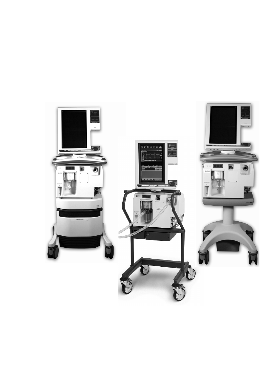
Some illustrations and images are shown with a ready-to-assemble
(RTA) cart, Puritan Bennett 800 Series Ventilator Compressor
Mount Cart, or a Puritan Bennett 800 Series Ventilator Pole Cart.
Please note that these images are for illustrative purposes only,
and regardless of which cart you have, the required information is
provided.
, Volume Ventilation
The term “RTA cart” refers to the ready-to-assemble cart and any
earlier cart versions.
Puritan Bennett 800 Series Ventilator System Operator’s and Technical Reference Manual
vi
Page 9

Contents
Operator’s Manual
1 Introduction OP 1-1
1.1 Technical description. . . . . . . . . . . . . . . . . . . . . . . . . .OP 1-3
1.1.1 General background . . . . . . . . . . . . . . . . . . . . . . OP 1-3
1.1.2 Pressure and flow triggering . . . . . . . . . . . . . . . .OP 1-5
1.1.3 Breathing gas mixture . . . . . . . . . . . . . . . . . . . . .OP 1-5
1.1.4 Inspiratory pneumatics . . . . . . . . . . . . . . . . . . . . OP 1-6
1.1.5 Patient circuit . . . . . . . . . . . . . . . . . . . . . . . . . . . OP 1-6
1.1.6 AC mains and backup power system . . . . . . . . . . OP 1-7
1.1.7 Ventilator emergency states. . . . . . . . . . . . . . . . .OP 1-8
1.2 Graphic user interface . . . . . . . . . . . . . . . . . . . . . . . . . OP 1-9
1.3 User interface controls and indicators . . . . . . . . . . . . .OP 1-11
1.3.1 Onscreen symbols and abbreviations . . . . . . . . . . OP 1-19
1.4 Ventilator system labeling symbols. . . . . . . . . . . . . . . . OP 1-25
2 How to set up the Puritan Bennett 840 ventilator OP 2-1
2.1 How to connect the electrical supply . . . . . . . . . . . . .OP 2-4
2.2 How to connect the air and oxygen supplies . . . . . . . .OP 2-10
2.3 How to connect the patient circuit components . . . . .OP 2-13
2.3.1 How to select and connect a patient circuit . . . . . OP 2-14
2.3.2 How to install the expiratory filter
and collector vial . . . . . . . . . . . . . . . . . . . . . . . . .OP 2-17
2.3.3 How to install the flex arm. . . . . . . . . . . . . . . . . .OP 2-21
2.3.4 How to install the humidifier . . . . . . . . . . . . . . . . OP 2-23
2.3.5 How to use the ventilator cart . . . . . . . . . . . . . . .OP 2-26
3 How to run Short Self Test (SST) OP 3-1
3.1 Introduction to SST . . . . . . . . . . . . . . . . . . . . . . . . . . .OP 3-1
3.2 When to run SST . . . . . . . . . . . . . . . . . . . . . . . . . . . . . OP 3-2
3.3 SST components and requirements . . . . . . . . . . . . . . .OP 3-3
3.4 SST Procedure . . . . . . . . . . . . . . . . . . . . . . . . . . . . . . .OP 3-4
3.5 SST Results. . . . . . . . . . . . . . . . . . . . . . . . . . . . . . . . . . OP 3-12
3.5.1 How to interpret individual SST test results . . . . . OP 3-14
Puritan Bennett 800 Series Ventilator System Operator’s and Technical Reference Manual
vii
Page 10

Contents
3.5.2 SST outcomes . . . . . . . . . . . . . . . . . . . . . . . . . . . OP 3-15
4 How to use the Puritan Bennett 840 ventilator OP 4-1
4.1 Structure of user interface . . . . . . . . . . . . . . . . . . . . . . OP 4-2
4.2 Patient setup. . . . . . . . . . . . . . . . . . . . . . . . . . . . . . . . OP 4-3
4.2.1 How to ventilate with most recent
control parameters . . . . . . . . . . . . . . . . . . . . . . . OP 4-4
4.2.2 How to ventilate with new control parameters . . OP 4-4
4.2.3 Patient data and current settings. . . . . . . . . . . . . OP 4-8
4.2.4 Ideal Body Weight (IBW). . . . . . . . . . . . . . . . . . . OP 4-10
4.3 How to change the main ventilator control
parameters . . . . . . . . . . . . . . . . . . . . . . . . . . . . . . . . . OP 4-17
4.4 Ideal Body Weight (IBW), vent type, mode,
and other changes . . . . . . . . . . . . . . . . . . . . . . . . . . . . OP 4-17
4.5 How to select a constant timing variable during
respiratory rate changes . . . . . . . . . . . . . . . . . . . . . . . OP 4-19
4.6 How to change apnea ventilation settings. . . . . . . . . . OP 4-21
4.7 How to set alarms OP 4-22
4.8 How to change other settings . . . . . . . . . . . . . . . . . . . OP 4-24
4.9 Expiratory pause maneuvers . . . . . . . . . . . . . . . . . . . . OP 4-25
4.10 Inspiratory pause maneuvers. . . . . . . . . . . . . . . . . . . OP 4-26
4.11 How to interpret inspiratory pause maneuver
results for static compliance and resistance. . . . . . . . OP 4-28
4.12 How to use NIV. . . . . . . . . . . . . . . . . . . . . . . . . . . . . OP 4-29
4.12.1 NIV intended use . . . . . . . . . . . . . . . . . . . . . . . OP 4-29
4.12.2 NIV breathing interfaces . . . . . . . . . . . . . . . . . . OP 4-29
4.12.3 NIV setup . . . . . . . . . . . . . . . . . . . . . . . . . . . . . OP 4-30
4.12.4 High spontaneous inspiratory time limit setting. OP 4-34
4.12.5 Apnea setup . . . . . . . . . . . . . . . . . . . . . . . . . . . OP 4-34
4.12.6 Alarm setup. . . . . . . . . . . . . . . . . . . . . . . . . . . . OP 4-34
4.12.7 Changing patient from INVASIVE to
NIV Vent Type . . . . . . . . . . . . . . . . . . . . . . . . . OP 4-36
4.12.8 Changing patient from NIV to
INVASIVE Vent Type . . . . . . . . . . . . . . . . . . . . . OP 4-37
4.12.9 NIV patient data . . . . . . . . . . . . . . . . . . . . . . . . OP 4-38
viii
Puritan Bennett 800 Series Ventilator System Operator’s and Technical Reference Manual
Page 11

Contents
5 How to handle alarms OP 5-1
5.1 Ventilator alarm classifications . . . . . . . . . . . . . . . . . . .OP 5-1
5.2 Alarm silence . . . . . . . . . . . . . . . . . . . . . . . . . . . . . . . . OP 5-2
5.3 Alarm reset . . . . . . . . . . . . . . . . . . . . . . . . . . . . . . . . . OP 5-5
5.4 Alarm log. . . . . . . . . . . . . . . . . . . . . . . . . . . . . . . . . . .OP 5-6
5.5 Alarm volume . . . . . . . . . . . . . . . . . . . . . . . . . . . . . . . OP 5-7
5.6 Alarm messages. . . . . . . . . . . . . . . . . . . . . . . . . . . . . .OP 5-8
6 How to view graphics OP 6-1
6.1 Graphics display function. . . . . . . . . . . . . . . . . . . . . . .OP 6-1
6.2 How to set up a graphics display . . . . . . . . . . . . . . . . . OP 6-3
6.3 Graphics display details and calculations . . . . . . . . . . . OP 6-4
6.4 How to adjust displayed graphics. . . . . . . . . . . . . . . . .OP 6-5
6.5 The graphics display FREEZE function . . . . . . . . . . . . .OP 6-6
6.6 How to print patient data graphics . . . . . . . . . . . . . . . OP 6-7
6.7 Automatic display of graphics . . . . . . . . . . . . . . . . . . .OP 6-7
6.8 When graphics are not accessible . . . . . . . . . . . . . . . . OP 6-8
7 Preventive maintenance OP 7-1
7.1 How to dispose of used parts. . . . . . . . . . . . . . . . . . . . OP 7-1
7.2 How to clean, disinfect and sterilize parts . . . . . . . . . . .OP 7-2
7.2.1 How to clean components. . . . . . . . . . . . . . . . . .OP 7-6
7.3 Disinfection and sterilization . . . . . . . . . . . . . . . . . . . . OP 7-6
7.4 Preventive maintenance procedures for the operator . . OP 7-8
7.4.1 Total operational hours . . . . . . . . . . . . . . . . . . . . OP 7-9
7.4.2 Inspiratory and expiratory bacteria filters . . . . . . . OP 7-12
7.4.3 Daily or as required: collector vial and drain bag . OP 7-14
7.4.3.1 How to remove the collector vial . . . . . . . . .OP 7-14
7.4.3.2 How to remove the drain bag . . . . . . . . . . .OP 7-14
7.4.4 Daily or as required: in-line water traps . . . . . . . . OP 7-16
7.4.5 Every 250 hours: compressor inlet filter . . . . . . . .OP 7-16
7.4.6 Every year: ventilator inspection. . . . . . . . . . . . . . OP 7-17
7.4.7 Every year or as necessary: oxygen sensor . . . . . .OP 7-17
7.4.7.1 Oxygen sensor replacement procedure . . . . OP 7-18
7.5 Additional preventive maintenance procedures . . . . . . OP 7-24
Puritan Bennett 800 Series Ventilator System Operator’s and Technical Reference Manual
ix
Page 12

Contents
7.6 Storage . . . . . . . . . . . . . . . . . . . . . . . . . . . . . . . . . . . . OP 7-26
7.7 Repacking and shipping . . . . . . . . . . . . . . . . . . . . . . . OP 7-26
A Specifications OP A-1
A.1 Physical characteristics . . . . . . . . . . . . . . . . . . . . . . . . OP A-2
A.2 Environmental requirements . . . . . . . . . . . . . . . . . . . . OP A-5
A.3 Pneumatic specifications . . . . . . . . . . . . . . . . . . . . . . . OP A-6
A.4 Electrical specifications . . . . . . . . . . . . . . . . . . . . . . . . OP A-7
A.5 Compliance and approvals . . . . . . . . . . . . . . . . . . . . . OP A-11
A.5.1 Manufacturer’s Declaration . . . . . . . . . . . . . . . . . OP A-12
A.6 Technical specifications. . . . . . . . . . . . . . . . . . . . . . . . OP A-22
A.7 Ranges, resolutions, and accuracies. . . . . . . . . . . . . . . OP A-29
A.7.1 Recommended limits . . . . . . . . . . . . . . . . . . . . . OP A-29
A.7.2 Software options. . . . . . . . . . . . . . . . . . . . . . . . . OP A-30
B Part numbers OP B-1
C Pneumatic schematic OP C-1
D Alarm and oxygen sensor calibration testing OP D-1
D.1 Alarm test. . . . . . . . . . . . . . . . . . . . . . . . . . . . . . . . . . OP D-1
D.2 Oxygen sensor calibration test . . . . . . . . . . . . . . . . . . OP D-7
E Remote alarm and RS-232 ports OP E-1
E.1 Remote alarm port . . . . . . . . . . . . . . . . . . . . . . . . . . . OP E-2
E.2 RS-232 port. . . . . . . . . . . . . . . . . . . . . . . . . . . . . . . . . OP E-3
E.3 How to configure the RS-232 ports . . . . . . . . . . . . . . . OP E-4
E.4 Printers and cables . . . . . . . . . . . . . . . . . . . . . . . . . . . OP E-5
E.5 RS-232 port commands. . . . . . . . . . . . . . . . . . . . . . . . OP E-7
Puritan Bennett 800 Series Ventilator System Operator’s and Technical Reference Manual
x
Page 13

Contents
Technical Reference
1 Introduction to breath delivery TR 1-1
2 Detecting and initiating inspiration TR 2-1
2.1 Internally triggered inspiration. . . . . . . . . . . . . . . . . . .TR 2-2
2.1.1 Pressure sensitivity . . . . . . . . . . . . . . . . . . . . . . . TR 2-2
2.1.2 Flow sensitivity . . . . . . . . . . . . . . . . . . . . . . . . . . TR 2-4
2.1.3 Time-cycled inspiration . . . . . . . . . . . . . . . . . . . . TR 2-6
2.2 Operator-triggered inspiration . . . . . . . . . . . . . . . . . . . TR 2-6
3 Detecting and initiating exhalation TR 3-1
3.1 Internally initiated exhalation. . . . . . . . . . . . . . . . . . . . TR 3-1
3.1.1 Time-cycled exhalation . . . . . . . . . . . . . . . . . . . .TR 3-1
3.1.2 End-inspiratory flow method . . . . . . . . . . . . . . . .TR 3-2
3.1.3 Airway pressure method . . . . . . . . . . . . . . . . . . .TR 3-3
3.2 Backup limits . . . . . . . . . . . . . . . . . . . . . . . . . . . . . . . . TR 3-4
3.2.1 Time limit . . . . . . . . . . . . . . . . . . . . . . . . . . . . . .TR 3-4
3.2.2 High circuit pressure limit . . . . . . . . . . . . . . . . . . TR 3-4
3.2.3 High ventilator pressure limit. . . . . . . . . . . . . . . . TR 3-4
4 Mandatory breath delivery TR 4-1
4.1 Comparison of pressure- and volume-based
mandatory breaths . . . . . . . . . . . . . . . . . . . . . . . . . . . TR 4-1
4.2 Compliance compensation for volume-based
mandatory breaths . . . . . . . . . . . . . . . . . . . . . . . . . . . TR 4-3
4.3 BTPS compensation for volume-based
mandatory breaths . . . . . . . . . . . . . . . . . . . . . . . . . . . TR 4-5
4.4 Manual inspiration. . . . . . . . . . . . . . . . . . . . . . . . . . . . TR 4-5
5 Spontaneous breath delivery TR 5-1
6 Assist/control (A/C) mode TR 6-1
6.1 Breath delivery in A/C . . . . . . . . . . . . . . . . . . . . . . . . .TR 6-1
6.2 Rate change during A/C . . . . . . . . . . . . . . . . . . . . . . .TR 6-3
Puritan Bennett 800 Series Ventilator System Operator’s and Technical Reference Manual
xi
Page 14

Contents
6.3 Changing to A/C mode. . . . . . . . . . . . . . . . . . . . . . . . TR 6-3
7 Synchronous intermittent mandatory ventilation
(SIMV) TR 7-1
7.1 Breath delivery in SIMV . . . . . . . . . . . . . . . . . . . . . . . . TR 7-3
7.2 Apnea ventilation in SIMV . . . . . . . . . . . . . . . . . . . . . . TR 7-4
7.3 Changing to SIMV mode. . . . . . . . . . . . . . . . . . . . . . . TR 7-5
7.4 Rate change during SIMV . . . . . . . . . . . . . . . . . . . . . . TR 7-7
8 Spontaneous (SPONT) mode TR 8-1
8.1 Breath delivery in SPONT . . . . . . . . . . . . . . . . . . . . . . TR 8-1
8.2 Changing to SPONT mode . . . . . . . . . . . . . . . . . . . . . TR 8-1
9 Apnea ventilation TR 9-1
9.1 Apnea detection . . . . . . . . . . . . . . . . . . . . . . . . . . . . . TR 9-1
9.2 Transition to apnea ventilation . . . . . . . . . . . . . . . . . . TR 9-3
9.3 Key entries during apnea ventilation . . . . . . . . . . . . . . TR 9-3
9.4 Resetting apnea ventilation. . . . . . . . . . . . . . . . . . . . . TR 9-3
9.4.1 Resetting to A/C . . . . . . . . . . . . . . . . . . . . . . . . . TR 9-4
9.4.2 Resetting to SIMV . . . . . . . . . . . . . . . . . . . . . . . . TR 9-4
9.4.3 Resetting to SPONT . . . . . . . . . . . . . . . . . . . . . . TR 9-4
9.5 Phasing in new apnea intervals . . . . . . . . . . . . . . . . . . TR 9-5
10
Detecting occlusion and disconnect TR 10-1
10.1 Occlusion . . . . . . . . . . . . . . . . . . . . . . . . . . . . . . . . . TR 10-1
10.2 Disconnect . . . . . . . . . . . . . . . . . . . . . . . . . . . . . . . . TR 10-3
10.3 Occlusions and disconnect annunciation. . . . . . . . . . TR 10-5
11 Phasing in setting changes TR 11-1
12 Ventilator settings TR 12-1
12.1 Apnea ventilation . . . . . . . . . . . . . . . . . . . . . . . . . . . TR 12-1
12.2 Circuit type and Ideal Body Weight (IBW) . . . . . . . . TR 12-2
Puritan Bennett 800 Series Ventilator System Operator’s and Technical Reference Manual
xii
Page 15

Contents
12.3 Disconnect sensitivity (D
12.4 Expiratory sensitivity (E
12.5 Expiratory time (T
) . . . . . . . . . . . . . . . . . . . . . . . . . .TR 12-4
E
) . . . . . . . . . . . . . . . . . . TR 12-3
SENS
). . . . . . . . . . . . . . . . . . . .TR 12-3
SENS
12.6 Flow pattern . . . . . . . . . . . . . . . . . . . . . . . . . . . . . . . TR 12-4
12.7 Flow sensitivity (V
12.8 High spontaneous inspiratory time limit (2T
). . . . . . . . . . . . . . . . . . . . . . . .TR 12-5
SENS
). .TR 12-6
I SPONT
12.9 Humidification type . . . . . . . . . . . . . . . . . . . . . . . . . . TR 12-7
12.10 I:E ratio . . . . . . . . . . . . . . . . . . . . . . . . . . . . . . . . . . TR 12-7
12.11 Ideal body weight (IBW) . . . . . . . . . . . . . . . . . . . . . TR 12-7
12.12 Inspiratory pressure (P
12.13 Inspiratory time (T
) . . . . . . . . . . . . . . . . . . . . . . TR 12-8
I
) . . . . . . . . . . . . . . . . . . . . . . . . . TR 12-8
I
12.14 Mode and mandatory breath type. . . . . . . . . . . . . . TR 12-9
12.15 O
12.16 Peak inspiratory flow (V
% . . . . . . . . . . . . . . . . . . . . . . . . . . . . . . . . . . . .TR 12-12
2
) . . . . . . . . . . . . . . . . . .TR 12-13
MAX
12.17 PEEP . . . . . . . . . . . . . . . . . . . . . . . . . . . . . . . . . . . .TR 12-13
12.17.1 PEEP restoration. . . . . . . . . . . . . . . . . . . . . . . . TR 12-14
12.18 Plateau time (T
12.19 Pressure sensitivity (P
12.20 Pressure support (P
) . . . . . . . . . . . . . . . . . . . . . . . . . .TR 12-14
PL
) . . . . . . . . . . . . . . . . . . . . TR 12-15
SENS
) . . . . . . . . . . . . . . . . . . . . . TR 12-15
SUPP
12.21 Respiratory rate (f) . . . . . . . . . . . . . . . . . . . . . . . . . . TR 12-16
12.22 Rise time % . . . . . . . . . . . . . . . . . . . . . . . . . . . . . . . TR 12-16
12.23 Safety ventilation . . . . . . . . . . . . . . . . . . . . . . . . . . . TR 12-17
12.24 Spontaneous breath type. . . . . . . . . . . . . . . . . . . . . TR 12-18
12.25 Tidal volume (V
). . . . . . . . . . . . . . . . . . . . . . . . . . . TR 12-19
T
12.26 Vent type. . . . . . . . . . . . . . . . . . . . . . . . . . . . . . . . . TR 12-19
13 Alarms TR 13-1
13.1 Alarm handling . . . . . . . . . . . . . . . . . . . . . . . . . . . . . TR 13-1
13.1.1 Alarm messages. . . . . . . . . . . . . . . . . . . . . . . . .TR 13-3
13.1.2 Alarm summary . . . . . . . . . . . . . . . . . . . . . . . . .TR 13-5
13.2 AC POWER LOSS alarm . . . . . . . . . . . . . . . . . . . . . . . TR 13-22
13.3 APNEA alarm . . . . . . . . . . . . . . . . . . . . . . . . . . . . . . .TR 13-22
13.4 CIRCUIT DISCONNECT alarm . . . . . . . . . . . . . . . . . . TR 13-23
13.5 DEVICE ALERT alarm . . . . . . . . . . . . . . . . . . . . . . . . . TR 13-23
13.6 High circuit pressure (P
Puritan Bennett 800 Series Ventilator System Operator’s and Technical Reference Manual
) alarm. . . . . . . . . . . . . . TR 13-24
PEAK
xiii
Page 16

Contents
13.7 High delivered O2% (O2%) alarm . . . . . . . . . . . . . . TR 13-25
13.8 High exhaled minute volume (V
13.9 High exhaled tidal volume (V
TE
13.10 High inspired tidal volume alarm (V
V
TI SPONT
13.11 High respiratory rate (f
) . . . . . . . . . . . . . . . . . . . . . . . . . . . . . . . . . . TR 13-26
) alarm . . . . . . . . . . . . . TR 13-27
TOT
13.12 INSPIRATION TOO LONG alarm . . . . . . . . . . . . . . . TR 13-27
13.13 Low circuit pressure alarm (P
13.14 Low delivered O
% (O2%) alarm . . . . . . . . . . . . . TR 13-28
2
PEAK
13.15 Low exhaled mandatory tidal volume
(V
TE MAND
) alarm . . . . . . . . . . . . . . . . . . . . . . . . . . . . TR 13-29
13.16 Low exhaled spontaneous tidal volume
(V
TE SPONT
) alarm . . . . . . . . . . . . . . . . . . . . . . . . . . . . TR 13-30
13.17 Low exhaled total minute volume (V
13.18 PROCEDURE ERROR alarm. . . . . . . . . . . . . . . . . . . . TR 13-31
14 Patient data TR 14-1
14.1 Delivered O2% . . . . . . . . . . . . . . . . . . . . . . . . . . . . . TR 14-1
14.2 End expiratory pressure (PEEP) . . . . . . . . . . . . . . . . . TR 14-2
14.3 End inspiratory pressure (P
14.4 Exhaled minute volume (V
14.5 Exhaled tidal volume (V
TE
14.6 I:E ratio (I:E) . . . . . . . . . . . . . . . . . . . . . . . . . . . . . . . TR 14-4
14.7 Intrinsic (auto) PEEP (PEEP
(PEEP
14.8 Mean circuit pressure (P
14.9 Peak circuit pressure (P
14.10 Plateau pressure (P
) . . . . . . . . . . . . . . . . . . . . . . . . . . . . . . . . . TR 14-5
TOT
MEAN
PEAK
) . . . . . . . . . . . . . . . . . . . . . . . TR 14-6
PL
14.11 Spontaneous minute volume (V
14.12 Static compliance and resistance (C
14.13 Total respiratory rate (f
TOT
) . . . . . . . . . . . . . . . . TR 14-2
I END
) . . . . . . . . . . . . . . . . TR 14-3
E TOT
) . . . . . . . . . . . . . . . . . . . . TR 14-4
) and total PEEP
I
). . . . . . . . . . . . . . . . . . TR 14-5
) . . . . . . . . . . . . . . . . . . . TR 14-5
) . . . . . . . . . . . . . . . . . . . TR 14-13
) alarm. . . . . . TR 13-25
ETOT
) alarm . . . . . . . . . . TR 13-26
TI
, V
TI MAND
,
) . . . . . . . . . . . . . TR 13-28
) alarm . TR 13-30
E TOT
E SPONT
) . . . . . . . . . TR 14-6
STAT
and R
). TR 14-7
STAT
15 Safety net TR 15-1
15.1 Patient problems. . . . . . . . . . . . . . . . . . . . . . . . . . . . TR 15-1
15.2 System faults. . . . . . . . . . . . . . . . . . . . . . . . . . . . . . . TR 15-2
Puritan Bennett 800 Series Ventilator System Operator’s and Technical Reference Manual
xiv
Page 17

Contents
15.3 Ongoing background checks. . . . . . . . . . . . . . . . . . . TR 15-3
15.4 Hardware monitoring circuitry. . . . . . . . . . . . . . . . . .TR 15-4
15.5 Power on self test (POST). . . . . . . . . . . . . . . . . . . . . .TR 15-5
15.6 Short self test (SST) . . . . . . . . . . . . . . . . . . . . . . . . . . TR 15-5
15.7 Extended self test (EST) . . . . . . . . . . . . . . . . . . . . . . . TR 15-5
15.8 Oxygen sensor calibration . . . . . . . . . . . . . . . . . . . . . TR 15-6
15.9 Exhalation valve calibration . . . . . . . . . . . . . . . . . . . . TR 15-6
15.10 Ventilator inoperative test . . . . . . . . . . . . . . . . . . . .TR 15-6
15.11 Flow sensor offset calibration . . . . . . . . . . . . . . . . . . TR 15-7
15.12 Atmospheric pressure transducer calibration . . . . . . TR 15-7
16 Power on self test (POST) TR 16-1
16.1 Safety . . . . . . . . . . . . . . . . . . . . . . . . . . . . . . . . . . . . TR 16-1
16.2 POST characteristics. . . . . . . . . . . . . . . . . . . . . . . . . .TR 16-2
16.3 POST following power interruptions . . . . . . . . . . . . .TR 16-3
16.4 POST fault handling. . . . . . . . . . . . . . . . . . . . . . . . . . TR 16-4
16.5 POST system interface . . . . . . . . . . . . . . . . . . . . . . . .TR 16-4
16.6 POST user interface . . . . . . . . . . . . . . . . . . . . . . . . . .TR 16-5
17 Short self test (SST) TR 17-1
18 Extended self test (EST) TR 18-1
18.1 EST results . . . . . . . . . . . . . . . . . . . . . . . . . . . . . . . . .TR 18-2
18.2 EST failure handling. . . . . . . . . . . . . . . . . . . . . . . . . .TR 18-3
18.3 EST safety considerations . . . . . . . . . . . . . . . . . . . . . . TR 18-3
19 RS-232 commands TR 19-1
19.1 RSET command . . . . . . . . . . . . . . . . . . . . . . . . . . . . .TR 19-1
19.2 SNDA command . . . . . . . . . . . . . . . . . . . . . . . . . . . .TR 19-1
19.3 SNDF command . . . . . . . . . . . . . . . . . . . . . . . . . . . .TR 19-8
Puritan Bennett 800 Series Ventilator System Operator’s and Technical Reference Manual
xv
Page 18

Contents
This page is intentionally blank.
xvi
Puritan Bennett 800 Series Ventilator System Operator’s and Technical Reference Manual
Page 19

Figures
Operator’s Manual
Figure 1-1. Puritan Bennett 840 Ventilator System block diagram . . OP 1-4
Figure 1-2. Puritan Bennett 840 Ventilator System
Graphic User Interface (GUI) . . . . . . . . . . . . . . . . . . . . . . OP 1-10
Figure 2-1. How to lift the ventilator components . . . . . . . . . . . . . . OP 2-2
Figure 2-2. How to connect the ventilator power cord . . . . . . . . . . . OP 2-6
Figure 2-3. Ventilator power switch, AC indicator, and AC panel . . . OP 2-7
Figure 2-4. Power cord storage on the RTA cart . . . . . . . . . . . . . . . . OP 2-8
Figure 2-5. Power cord storage on the newer Puritan Bennett
800 Series Ventilator Compressor Mount Cart and
Puritan Bennett 800 Series Ventilator Pole Cart (shown) . OP 2-9
Figure 2-6. How to connect the air and oxygen supplies . . . . . . . . . OP 2-12
Figure 2-7. How to connect the patient circuit . . . . . . . . . . . . . . . . . OP 2-16
Figure 2-8. How to install the expiratory filter and collector vial . . . . OP 2-18
Figure 2-9. How to use the collector vial with or without
the drain bag . . . . . . . . . . . . . . . . . . . . . . . . . . . . . . . . . OP 2-19
Figure 2-10. How to install the flex arm on RTA cart . . . . . . . . . . . . . . OP 2-21
Figure 2-11. How to install the flex arm on the newer
Puritan Bennett 800 Series Ventilator Compressor
Mount Cart or Puritan Bennett 800 Series Ventilator
Pole Cart . . . . . . . . . . . . . . . . . . . . . . . . . . . . . . . . . . . . OP 2-22
Figure 2-12. How to install the humidifier (Fisher & Paykel
version shown) for ventilators mounted on RTA carts . . . OP 2-25
Figure 2-13. Location of cart lot number label. . . . . . . . . . . . . . . . . . . OP 2-27
Figure 2-14. How to lock and unlock the RTA cart’s front wheels. . . . . OP 2-28
Figure 2-15. How to lock and unlock the Puritan Bennett 800 Series
Ventilator Compressor Mount Cart or Puritan Bennett
800 Series Ventilator Pole Cart front wheels. . . . . . . . . . . OP 2-28
Figure 3-1. Test button location . . . . . . . . . . . . . . . . . . . . . . . . . . . . OP 3-5
Figure 4-1. Touch screen user interface . . . . . . . . . . . . . . . . . . . . . . . OP 4-2
Figure 4-2. Ventilator Startup screen . . . . . . . . . . . . . . . . . . . . . . . . OP 4-3
Figure 4-3. Touch screen appearance during normal ventilation
(shown with alarm silence and
100% O
T
Figure 4-4.
Figure 4-5. Alarm setup. . . . . . . . . . . . . . . . . . . . . . . . . . . . . . . . . . . OP 4-23
(or TH) selected as the constant during rate change. . . OP 4-20
I
/CAL in progress) . . . . . . . . . . . . . . . . . . . . . . . OP 4-9
2
Puritan Bennett 800 Series Ventilator System Operator’s and Technical Reference Manual
Figures
xvii
Page 20

Figures
Figure 4-6. New patient setup screen — NIV . . . . . . . . . . . . . . . . . . OP 4-31
Figure 4-7. NIV ventilator settings screen . . . . . . . . . . . . . . . . . . . . . OP 4-33
Figure 4-8. New patient default alarm settings . . . . . . . . . . . . . . . . . OP 4-35
Figure 4-9. More patient data screen — NIV. . . . . . . . . . . . . . . . . . . OP 4-38
Figure 5-1. Alarm indicators . . . . . . . . . . . . . . . . . . . . . . . . . . . . . . . OP 5-1
Figure 5-2. Alarm Silence in Progress indicator (lower screen). . . . . . OP 5-4
Figure 5-3. Alarm log . . . . . . . . . . . . . . . . . . . . . . . . . . . . . . . . . . . . OP 5-6
Figure 5-4. Alarm message format . . . . . . . . . . . . . . . . . . . . . . . . . . OP 5-9
Figure 6-1. Pressure-volume loop . . . . . . . . . . . . . . . . . . . . . . . . . . . OP 6-2
Figure 6-2. Flow-volume loop. . . . . . . . . . . . . . . . . . . . . . . . . . . . . . OP 6-3
Figure 7-1. How to empty the collector vial and seal the drain bag . OP 7-15
Figure 7-2. 806 compressor with inlet filter. . . . . . . . . . . . . . . . . . . . OP 7-17
Figure 7-3. Dislodge the O
Figure 7-4. Open O
Figure 7-5. Locate O
sensor access port . . . . . . . . . . . . . . . . . . . . . . OP 7-21
2
2
Figure A-1. Recommended patient circuit configurations . . . . . . . . . OP A-27
Figure B-1. Ventilator accessories . . . . . . . . . . . . . . . . . . . . . . . . . . . OP B-2
Figure B-2. Ventilator accessories (Puritan Bennett 800 Series
Ventilator Compressor Mount Cart shown) . . . . . . . . . . OP B-11
Figure B-3. Puritan Bennett 840 Ventilator System shown
mounted on Puritan Bennet 800 Series Ventilator
Pole Cart . . . . . . . . . . . . . . . . . . . . . . . . . . . . . . . . . . . . OP B-19
Figure C-1. Pneumatic schematic . . . . . . . . . . . . . . . . . . . . . . . . . . . OP C-1
Figure E-1. Remote alarm and RS-232 ports . . . . . . . . . . . . . . . . . . . OP E-1
Figure E-2. Remote alarm port pinout (view from back of GUI). . . . . OP E-2
Figure E-3. RS-232 serial port pinout . . . . . . . . . . . . . . . . . . . . . . . . OP E-3
sensor access cover . . . . . . . . . . . . . . . . OP 7-20
2
sensor . . . . . . . . . . . . . . . . . . . . . . . . . . . . . . OP 7-22
Technical Reference
Figure 2-1. Declaring inspiration using pressure sensitivity . . . . . . . . TR 2-3
Figure 2-2. Declaring inspiration using flow sensitivity . . . . . . . . . . . TR 2-4
Figure 2-3. Time-cycled inspiration . . . . . . . . . . . . . . . . . . . . . . . . . TR 2-6
Figure 3-1. Initiating exhalation using the end-inspiratory
flow method . . . . . . . . . . . . . . . . . . . . . . . . . . . . . . . . . TR 3-2
Figure 3-2. Initiating exhalation using the airway pressure method . TR 3-3
Figure 6-1. A/C mode, no patient effort detected . . . . . . . . . . . . . . TR 6-2
Figure 6-2. A/C mode, patient effort detected . . . . . . . . . . . . . . . . . TR 6-2
Puritan Bennett 800 Series Ventilator System Operator’s and Technical Reference Manual
xviii
Page 21

Figures
Figure 6-3. A/C mode, VIM and PIM breaths . . . . . . . . . . . . . . . . . . TR 6-2
Figure 7-1. SIMV breath cycle (mandatory and
spontaneous intervals) . . . . . . . . . . . . . . . . . . . . . . . . . . TR 7-1
Figure 7-2. SIMV breath cycle, PIM delivered within
mandatory interval . . . . . . . . . . . . . . . . . . . . . . . . . . . . . TR 7-2
Figure 7-3. SIMV breath cycle, PIM not delivered within
mandatory interval . . . . . . . . . . . . . . . . . . . . . . . . . . . . . TR 7-2
Figure 7-4. Apnea ventilation in SIMV . . . . . . . . . . . . . . . . . . . . . . . TR 7-5
Figure 9-1. Apnea interval equals breath period . . . . . . . . . . . . . . . . TR 9-2
Figure 9-2. Apnea interval greater than breath period . . . . . . . . . . . TR 9-2
Figure 9-3. Apnea interval less than breath period . . . . . . . . . . . . . . TR 9-2
Figure 12-1. Puritan Bennett 840 Ventilator System modes
and breath types . . . . . . . . . . . . . . . . . . . . . . . . . . . . . . . TR 12-11
Figure 13-1. Alarm message format (upper GUI screen) . . . . . . . . . . . TR 13-3
Puritan Bennett 800 Series Ventilator System Operator’s and Technical Reference Manual
xix
Page 22

Figures
This page is intentionally blank.
xx
Puritan Bennett 800 Series Ventilator System Operator’s and Technical Reference Manual
Page 23

Tables
Operator’s Manual
Table 1-1. Controls and indicators . . . . . . . . . . . . . . . . . . . . . . . . . . OP 1-11
Table 1-2. BDU indicators . . . . . . . . . . . . . . . . . . . . . . . . . . . . . . . . . OP 1-18
Table 1-3. Symbols and abbreviations . . . . . . . . . . . . . . . . . . . . . . . OP 1-19
Table 2-1. Patient circuit and IBW values. . . . . . . . . . . . . . . . . . . . . . OP 2-15
Table 3-1. SST test sequence. . . . . . . . . . . . . . . . . . . . . . . . . . . . . . . OP 3-8
Table 3-2. Individual SST test results . . . . . . . . . . . . . . . . . . . . . . . . . OP 3-14
Table 3-3. Overall SST outcomes. . . . . . . . . . . . . . . . . . . . . . . . . . . . OP 3-15
Table 4-1. Ideal Body Weight (IBW) based
on patient height (cm to kg) . . . . . . . . . . . . . . . . . . . . . . OP 4-10
Table 4-2. Determining IBW based
on patient height (ft., in. to lb.) . . . . . . . . . . . . . . . . . . . . OP 4-13
Table 4-3. Soft bound ranges for Ideal Body Weight and tube
Internal Diameter (ID) . . . . . . . . . . . . . . . . . . . . . . . . . . . OP 4-15
Table 4-4. Patient circuit and IBW values. . . . . . . . . . . . . . . . . . . . . . OP 4-16
Table 4-5. Monitored ventilator control parameters . . . . . . . . . . . . . OP 4-17
Table 4-5. Automatic settings changes — INVASIVE to NIV
on same patient . . . . . . . . . . . . . . . . . . . . . . . . . . . . . . . . OP 4-36
Table 4-6. Automatic settings changes — NIV to INVASIVE
on same patient . . . . . . . . . . . . . . . . . . . . . . . . . . . . . . . . OP 4-37
Table 5-1. Alarm messages . . . . . . . . . . . . . . . . . . . . . . . . . . . . . . . . OP 5-10
Table 7-1. Procedures to clean, disinfect, and sterilize parts. . . . . . . . OP 7-3
Table 7-2. Disinfection and sterilization procedures. . . . . . . . . . . . . . OP 7-7
Table 7-3. Operator preventive maintenance procedures
and frequency . . . . . . . . . . . . . . . . . . . . . . . . . . . . . . . . . OP 7-10
Table 7-4. Service preventive maintenance procedures and intervals . OP 7-25
Table A-1. Physical characteristics . . . . . . . . . . . . . . . . . . . . . . . . . . . OP A-3
Table A-2. Environmental requirements . . . . . . . . . . . . . . . . . . . . . . . OP A-5
Table A-3. Pneumatic specifications . . . . . . . . . . . . . . . . . . . . . . . . . . OP A-6
Table A-4. Electrical specifications . . . . . . . . . . . . . . . . . . . . . . . . . . . OP A-7
Table A-5. Compliance and approvals . . . . . . . . . . . . . . . . . . . . . . . . OP A-11
Table A-6. Electromagnetic Emissions . . . . . . . . . . . . . . . . . . . . . . . . OP A-13
Table A-7. Electromagnetic Immunity . . . . . . . . . . . . . . . . . . . . . . . . OP A-15
Table A-8. Electromagnetic Immunity – conducted and radiated RF . OP A-17
Puritan Bennett 800 Series Operator’s and Technical Reference Manual
xxi
Page 24

Tables
Table A-9. Recommended separation distances between
portable and mobile RF communications equipment
and the Puritan Bennett 840 Ventilator System . . . . . . . . OP A-19
Table A-10. Compliant cables . . . . . . . . . . . . . . . . . . . . . . . . . . . . . . . OP A-20
Table A-11. Technical specifications . . . . . . . . . . . . . . . . . . . . . . . . . . OP A-22
Table 1-12. Patient circuit configurations . . . . . . . . . . . . . . . . . . . . . . OP A-28
Table A-13. Ventilator settings . . . . . . . . . . . . . . . . . . . . . . . . . . . . . . OP A-30
Table A-14. Alarm settings . . . . . . . . . . . . . . . . . . . . . . . . . . . . . . . . . OP A-48
Table A-15. Patient data . . . . . . . . . . . . . . . . . . . . . . . . . . . . . . . . . . . OP A-54
Table A-16. Other Screens — displayed data. . . . . . . . . . . . . . . . . . . . OP A-60
Table B-1. Ventilator parts and accessories . . . . . . . . . . . . . . . . . . . . OP B-3
Table B-2. Ventilator parts and accessories . . . . . . . . . . . . . . . . . . . . OP B-12
Table B-3. Ventilator Pole Cart and accessories . . . . . . . . . . . . . . . . . OP B-20
Technical Reference
Table 4-1. Comparison of pressure- and volume-based
mandatory breaths . . . . . . . . . . . . . . . . . . . . . . . . . . . . . TR 4-2
Table 4-2. Compliance volume factors . . . . . . . . . . . . . . . . . . . . . . . TR 4-5
Table 5-1. Spontaneous breath delivery characteristics . . . . . . . . . . TR 5-1
Table 12-1. Modes and breath types . . . . . . . . . . . . . . . . . . . . . . . . . TR 12-9
Table 13-1. Alarm urgency levels . . . . . . . . . . . . . . . . . . . . . . . . . . . . TR 13-2
Table 13-2. Alarm summary . . . . . . . . . . . . . . . . . . . . . . . . . . . . . . . . TR 13-5
Table 13-3. Applicability of high inspired tidal volume alarm symbols. TR 13-26
Table 14-1. Inspiratory pause maneuver displays . . . . . . . . . . . . . . . . TR 14-9
Table 19-1. MISCA response. . . . . . . . . . . . . . . . . . . . . . . . . . . . . . . . TR 19-3
Table 19-2. MISCF response . . . . . . . . . . . . . . . . . . . . . . . . . . . . . . . . TR 19-9
Puritan Bennett 800 Series Operator’s and Technical Reference Manual
xxii
Page 25

CHAPTER
1 Introduction
The intended use of the Puritan Bennett™ 840 Ventilator System
is for acute and subacute care of infant, pediatric, and adult
patients. Software options, available from Puritan Bennett,
provide additional ventilation functions.
The Puritan Bennett 840 Ventilator System facilitates work of
breathing management, offers selectable modes of breath delivery,
and assists the practitioner in the selection of the most
appropriate ventilator control parameters for the patient. The user
interface is intuitive and easy to operate for those with prior
knowledge of ventilator operation.
The user interface includes DualView™ touch screens that display
monitored patient data for easy assessment of the patient’s
condition. The touch screens also display the current ventilator
control parameters.
The SandBox™ area on the touch screen allows the practitioner to
preview the selected ventilator control parameters prior to active
ventilation of the patient.
The SmartAlert™ system intercepts alarms, or events, provides
specific information about the cause, and prompts the user with
actions to resolve the reported condition(s).
1
The breath delivery unit (BDU) comprises the pneumatics and the
patient circuit.
The ventilator uses two independent Central Processing Units
(CPUs):
• Breath delivery unit (BDU) CPU
• Graphic user interface (GUI) CPU
The BDU CPU uses the ventilator control parameters, selected by
the practitioner, to deliver breaths to the patient. The BDU CPU
also runs continuous and extensive operational background
checks to ensure proper operation of the ventilator.
Puritan Bennett 800 Series Ventilator System Operator’s Manual
OP 1-1
Page 26

OP 1 Introduction
The GUI CPU monitors the ventilator and the ventilator/patient
interaction. The GUI CPU also monitors the operation of the BDU
CPU and prevents simultaneous failure of control and monitor
functions when a single fault is reported.
The Puritan Bennett 840 Ventilator System supplies mandatory or
spontaneous breaths with a preset level of positive end expiratory
pressure (PEEP), trigger sensitivity, and oxygen concentration. A
mandatory breath can either be pressure- or volume-controlled,
but it is always pressure-controlled in the optional BiLevelmode. A
spontaneous breath allows patient inspiratory flows of up to
200 L/min, with or without pressure support.
The optional 806 Compressor unit provides compressed air to the
BDU, and can be used in place of wall or bottled air. The
compressor unit is powered through and communicates with the
BDU.
The 802 Backup Power Source (BPS) or 803 Extended Backup
Power Source provides DC power to the BDU and GUI in the
event AC power is lost. A new, fully charged BPS runs the
ventilator (without a compressor or a humidifier) for at least 60
minutes (30 minutes on ventilators built prior to July 2007),
which allows transport of the patient and the ventilator within
the healthcare facility. The 803 extended BPS (available after
October 2009) can power the ventilator for at least four hours
under the same conditions.The same conditions apply,
respectively, to the one-hour or four-hour BPS assembly in the
Puritan Bennett 800 Series Ventilator Compressor Mount Cart and
the one-hour or four-hour batteries in the Puritan Bennett 800
Series Ventilator Pole Cart.
This manual tells you how to operate and perform simple
maintenance for the Puritan Bennett 840 Ventilator System.
Become familiar with this manual and accompanying labels
before attempting to operate or maintain the ventilator.
To ensure optimum performance of the Puritan Bennett
840 Ventilator System, Puritan Bennett strongly recommends
certified biomedical engineering technicians, or other personnel
with equivalent experience and training in the service of this type
of equipment, perform periodic maintenance on the ventilator.
For more information, contact your representative.
Puritan Bennett 800 Series Ventilator System Operator’s Manual
OP 1-2
Page 27

Introduction OP 1
1.1 Technical description
1.1.1 General background
The practitioner uses the GUI touch screens, the off-screen keys,
and GUI knob to select the ventilator control parameters and
input data (see Figure 1-1). The GUI CPU processes this
information and stores it in ventilator memory. The BDU CPU
uses this stored information to control and monitor the flow of
gas to and from the patient. The two CPUs communicate to
transfer and verify any new ventilator control parameters or alarm
limits. Each CPU then performs continuous background
verification of operational and data integrity.
Puritan Bennett 800 Series Ventilator System Operator’s Manual
OP 1-3
Page 28
OP 1 Introduction
Active exhalation valve
Pressure transducer
Flow sensor
Exhalation
module:
Expiratory
filter
Collector
vial
(Expiratory
limb)
(Inspiratory
limb)
Patient
circuit
Humidification
device
Inspiratory
filter
Oxygen
supply
Air
supply
Air
regulator
Oxygen
regulator
PSOLs
Safety valve
Oxygen sensor
Pressure transducers
Flow sensors
Inspiratory
module:
interface (GUI)
Graphic user
Puritan Bennett 800 Series Ventilator System Operator’s Manual
Figure 1-1. Puritan Bennett 840 Ventilator System block diagram
OP 1-4
Page 29

Introduction OP 1
1.1.2 Pressure and flow triggering
The ventilator uses flow or pressure triggering to recognize patient
effort. When pressure triggering is in effect, the ventilator monitors
pressure in the patient circuit. As the patient draws gas from the
circuit and airway pressure drops by at least the value selected for
pressure sensitivity, the ventilator delivers a breath.
When flow triggering (Flow-by
the difference between the inspiratory and expiratory flow sensor
measurements. As the patient inhales, the ventilator measures less
exhaled flow while the delivered flow remains constant. The
result is an increase in the difference between the inspiratory and
expiratory flows. When the difference is at least the operatorselected value for flow sensitivity, the ventilator delivers a breath.
If the patient is not inhaling, any difference between the delivered
and exhaled flow is due to sensor inaccuracy or leaks in the
patient system. To compensate for leaks in the patient system
which can cause autotriggering, the operator can increase the flow
sensitivity setting.
As a backup method of triggering inspiration, a pressure
sensitivity of 2 cmH
O is also in effect. This setting is the most
2
sensitive setting still large enough to avoid autotriggering, yet will
trigger with acceptable patient effort.
) is in effect, the ventilator monitors
1.1.3 Breathing gas mixture
Air and oxygen from cylinders, wall supplies, or compressor (air
only) enter the ventilator through hoses and fittings (the fittings
are available in several versions). Once inside the ventilator, air
and oxygen are regulated to pressures appropriate for the
ventilator, then mixed according to the selected O
The ventilator delivers the mixed air and oxygen through the
inspiratory module and out to the patient. The oxygen
concentration of the delivered gas is monitored here, using a
galvanic oxygen sensor. The galvanic sensor generates a voltage
proportional to the oxygen concentration. The ventilator reports
an alarm if the O
sensor is enabled and monitored oxygen
2
concentration is more than seven percent above or below the
O
% setting, or below 18% after the concentration stabilizes.
2
Puritan Bennett 800 Series Ventilator System Operator’s Manual
%.
2
OP 1-5
Page 30

OP 1 Introduction
The inspiratory manifold also includes a safety valve to relieve
patient pressure if necessary (for example, if the patient circuit is
kinked or occluded). The inspiratory module also corrects for gas
temperature and humidity, based on the practitioner-set
humidification type.
1.1.4 Inspiratory pneumatics
Ventilator inspiratory pneumatics consist of two parallel circuits:
one for oxygen and one for air. The primary elements of the
inspiratory pneumatics are two proportional solenoid valves
(PSOLs), which control the flow of gas delivered to the patient. Air
and oxygen flow sensors, along with pressure signals from the
patient circuit, provide feedback that the BDU CPU uses to
control the PSOLs.
As a result, the ventilator supplies mixed breathing gas to the
patient, based on the practitioner-set ventilator control
parameters. The mixed air and oxygen passes through the patient
circuit external to the ventilator. The system delivers the
breathing gas mixture to the patient at the patient wye, located in
the external patient circuit.
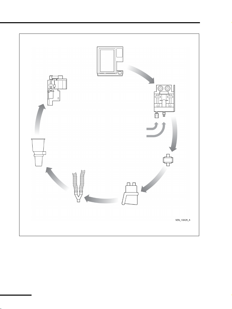
1.1.5 Patient circuit
The patient circuit comprises the components external to the
ventilator that route gas between the ventilator and the patient.
These components include:
•an inspiratory filter that protects against contamination
between the patient and ventilator
• a humidification device (optional) in line with the patient
circuit
• the inspiratory and expiratory limbs of the patient circuit that
conduct the breathing gas to and from the patient
•a collector vial that protects the expiratory pneumatics from
bulk moisture in the exhaled gas
•an expiratory filter that limits the escape of microorganisms and
particulates in the patient’s exhaled gas into the room air or
inside the ventilator exhalation pneumatics
Puritan Bennett 800 Series Ventilator System Operator’s Manual
OP 1-6
Page 31

Introduction OP 1
NOTE:
The ventilator actively controls the exhalation valve that the
software accurately positions throughout the patient’s inspiration
and exhalation. The exhalation valve allows the ventilator to
deliver aggressive breaths while pressure overshoots are
minimized, PEEP is controlled, and excess patient pressures are
relieved. The exhalation system monitors the exhaled gas leaving
the patient circuit for spirometry.
The Puritan Bennett 840 Ventilator System does not have the
capability to reduce pressure below the PEEP pressure during
the expiratory phase.
Throughout the respiratory cycle, pressure transducers monitor
inspiratory, expiratory, and atmospheric pressures. The
temperature of the exhaled gas is heated to a temperature above
its dew point to prevent condensation in the exhalation
compartment. Refer to Appendix C for a detailed diagram of the
ventilator’s pneumatic system and patient circuit.
1.1.6 AC mains and backup power system
The ventilator derives its power to operate from the AC mains
(wall) power or the backup power system (BPS). The design of the
BDU integral power supply protects against excessive voltages,
temperatures, or current draws. A power cord retainer prevents
accidental disconnection of the BDU from the AC mains. A power
switch cover on the front face of the BDU protects against spills
and accidental AC power-off.
The ventilator connects to the 802 or 803 BPS, which supplies DC
power to the ventilator if AC power is lost. A fully charged 802
BPS operating under nominal ambient conditions, can power the
ventilator for at least 60 minutes (30 minutes on ventilators built
prior to July 2007). The 803 extended BPS can power the
ventilator for at least 4 hours under the same conditions. Neither
BPS powers the compressor unit or the humidifier, if present. The
803 BPS must be used on Puritan Bennett 840 ventilators with
software version AB or higher (part number 4-070212-85) or
equivalent. The operation and alarms of the 803 BPS are identical
Puritan Bennett 800 Series Ventilator System Operator’s Manual
OP 1-7
Page 32

OP 1 Introduction
to the 802 BPS. The GUI indicates when the ventilator is operating
on the BPS, rather than AC mains.
When AC power is connected, it recharges the BPS. The BPS
continues to recharge from the AC power during normal
ventilator operation. If the ventilator is mounted on a Puritan
Bennett 800 Series Ventilator Compressor Mount Cart and has a
four-hour BPS or the ventilator is mounted on a Puritan Bennett
800 Series Ventilator Pole Cart with a four-hour battery, the
software version, battery life, and operating conditions are the
same as described for the 803 BPS. The battery life and operating
conditions for each cart with a one-hour BPS or one-hour battery
are equivalent to the description given for the 802 BPS.
1.1.7 Ventilator emergency states
Emergency states include ventilator inoperative and safety valve open
(SVO). When a ventilator inoperative condition occurs, it always
includes the SVO state. A SVO state can also occur independent of
a ventilator inoperative condition.
The following describe the two ventilator emergency states:
• Safety valve open (SVO): The ventilator
enters a SVO state if both air and
oxygen supplies are lost, or an
occlusion is detected, or the ventilator
enters the Ventilator Inoperative
condition.
The safety valve open (SVO) state allows
the patient to breathe room air
unassisted by the ventilator. The
ventilator remains in the SVO state until the condition that
caused the emergency state is corrected.
When the ventilator enters the SVO state, the SVO indicator
on the front face of the BDU illuminates, and a high-urgency
alarm sounds.
In case of a malfunction that prevents software from opening
the safety valve, there is also an analog circuit that opens the
safety valve if system pressure exceeds 100 to 120 cmH
Puritan Bennett 800 Series Ventilator System Operator’s Manual
OP 1-8
O.
2
Page 33

Introduction OP 1
•Ventilator inoperative: The ventilator
declares a ventilator inoperative
condition if a hardware failure or
critical software error occurs that could
compromise safe ventilation of the
patient.
When a ventilator inoperative
condition occurs, the ventilator
inoperative indicator on the front face
of the BDU illuminates and the ventilator enters the SVO state,
which in turns sounds a high-urgency alarm.
If a ventilator inoperative condition occurs, immediately
remove the ventilator from use until qualified service
personnel evaluate and correct the Ven t I n o p condition.
If the ventilator declares a ventilator inoperative state, the
power on self test (POST) must first verify power levels to the
ventilator are acceptable and the functions of the major
electronics systems are satisfactory before normal ventilation
can resume. Qualified service personnel must repair the
ventilator to correct the problem and execute EST successfully
before normal ventilation is allowed.
1.2 Graphic user interface
This section describes the graphic user interface (GUI), the GUI
keys, the GUI indicators, and the symbols you see on the GUI.
The graphic user interface (GUI) of the Puritan Bennett
840 Ventilator System comprises the DualView touch screens, the
off-screen keys located below the touch screens, and a knob. Use
the knob to set a given ventilator control parameter to its desired
value. Press the
of the knob — to enter the selected value or parameter into
memory.
Figure 1-2 identifies the components of the GUI, and the location
of information on the DualView touch screens.
ACCEPT key — the off-screen key above and right
Puritan Bennett 800 Series Ventilator System Operator’s Manual
OP 1-9
Page 34

OP 1 Introduction
Vital patient data
Alarm and ventilator status
Assorted patient data,
including graphical displays
Active alarm log, if applicable
Primary patient parameters
Setup of ventilator control
parameters, alarm limits,
breath timing parameters,
and other parameters
Symbol definitions
Prompt
area
Status
indicators
Off-screen
keys
CLEAR
key
ACCEPT
key
Knob
Upper screen:
monitored
information
(alarms,
patient data)
Lower screen:
ventilator
control
parameters
Figure 1-2. Puritan Bennett 840 Ventilator System Graphic User Interface
Puritan Bennett 800 Series Ventilator System Operator’s Manual
OP 1-10
(GUI)
Page 35

Introduction OP 1
1.3 User interface controls and indicators
Descriptions of the controls and indicators on the graphic user
interface are given in Table 1-1 below.
Table 1-1: Controls and indicators
Control or indicator Function
Screen lock key: When the yellow light on the screen lock key
is lit, the screen or off-screen controls (including the knob and
ACCEPT key) have no effect when touched until you press
the screen lock key again. New alarms automatically unlock
the screen and controls.
The screen lock allows you to clean the touch screen and
prevents inadvertent changes to settings and displays.
Alarm volume key: Allows you to adjust the alarm volume
when you hold down this key while turning the knob. You
cannot turn off the alarm volume.
Alarm silence key: Turns off the audible alarm sound for two
minutes. The yellow light on the alarm silence key illuminates
during the silence period. An ALARM SILENCE IN PROGRESS
indicator displays on the lower touch screen, along with a
CANCEL button, if there is not a higher-priority alarm display
active. To exit out of the alarm silence, touch the CANCEL
button.
The system automatically exits the alarm silence when the
two-minute interval times out. High-urgency alarms such as
Device Alerts, Safety Valve Open, Occlusion, and loss of either
gas supply cancel the alarm silence.
Each time you press the alarm silence key, the silence period
resets to two minutes. Each time you press the alarm silence
key (whether or not there is an active alarm), the keypress is
recorded in the alarm log.
Puritan Bennett 800 Series Ventilator System Operator’s Manual
OP 1-11
Page 36

OP 1 Introduction
Table 1-1: Controls and indicators
Control or indicator Function
Alarm reset key: Clears active alarms or resets high-urgency
alarms and cancels an active alarm silence., and is recorded in
the alarm log. Each time you press the reset key, it is recorded
in the alarm log, if there is an active alarm. You cannot reset a
DEVICE ALERT alarm.
Information key: Displays basic operating information about
the ventilator. Press the key to display a menu of information
topics, then touch the button corresponding to the desired
topic. Browse topical information using the , ,
, and buttons located in the information header.
Oxygen sensor calibration key: Older ventilators use the
100% O
INCREASE O
for two minutes and calibrates the oxygen sensor. The green
light on this key illuminates and a message (100% O
Progress) on the lower touch screen indicates 100% O
delivery is active. If you press the O
restarts the two-minute delivery interval. Press CANCEL to
stop the calibration. See page TR 15-6 for information on
calibrating the oxygen sensor.
Use the procedure in Section D.2 to test the oxygen sensor
calibration.
/CAL 2 min key and newer ventilators use the
2
2 min key. Delivers 100% oxygen (if available)
2
key again, the system
2
Cal in
2
2
Manual inspiration key: In A/C, SIMV, and SPONT modes,
delivers one manual breath to the patient in accordance with
the current mandatory breath parameters. In BILEVEL mode,
transitions from Low PEEP (PEEP
vice versa). To avoid breath stacking, a manual inspiration is
not delivered during inspiration or during the restricted phase
of exhalation.
You can use the MANUAL INSP key to supplement minute
volume or to assist measurement of a patient data parameter,
such as peak inspiratory pressure, or to run an inspiratory
pause maneuver in SPONT mode.
Puritan Bennett 800 Series Ventilator System Operator’s Manual
OP 1-12
) to High PEEP (PEEPH) (or
L
Page 37

Introduction OP 1
Table 1-1: Controls and indicators
Control or indicator Function
Expiratory pause key: Causes the ventilator to seal the
patient’s breathing circuit when the expiratory phase of a
designated breath, mandatory or spontaneous, is followed by
a time-cycled mandatory inspiration. An expiratory pause is
used to estimate PEEP
The ventilator performs two types of pause maneuver:
automatic, which you initiate by a momentary press of the
EXP PAUSE key, and manual, which you control by a
continuous press of the EXP PAUSE key. An automatic pause
performs the maneuver until the pressure stabilizes, then
takes its measurements. The pause lasts at least 0.5 second
and does not exceed 3.0 seconds.
During a manual pause, the ventilator takes its measurements
as soon as the pressure stabilizes or the pause ends. The
ventilator continues the maneuver until you release the EXP
PAU SE key. The pause cannot exceed 20 seconds.
Section 4.9 on page OP 4-25 describes in detail how to use
the EXP PAUSE key.
and PEEPI (autoPEEP).
TOT
Puritan Bennett 800 Series Ventilator System Operator’s Manual
OP 1-13
Page 38

OP 1 Introduction
Table 1-1: Controls and indicators
Control or indicator Function
Inspiratory pause key: Causes the ventilator to seal the
patient’s breathing circuit at the conclusion of the gas delivery
phase of a designated, volume- or pressure-based mandatory
inspiration. The inspiratory pause maneuver provides a means
to measure the patient’s static lung-thoracic compliance
), static resistance (R
(C
STAT
The inspiratory pause maneuver maintains the inflated state
of the lungs.
The ventilator performs two types of pause maneuver: auto-
matic, which is initiated by the momentary press of the INSP
PAU SE key, and manual, which you control by a continuous
press on the key.
An automatic pause performs the maneuver until the pressure
stabilizes, then the system takes its measurements. The pause
event lasts at least 0.5 second but no longer than 2.0 seconds.
In a manual pause, the maneuver continues until you release
the INSP PAUSE key, but cannot exceed 7 seconds. The ven-
tilator computes C
STAT
and R
and displays the values at the end of the maneuver. P
computed and updated continuously during the plateau, and
its value is frozen at the end of the plateau. Section 4.10 on
page OP 4-26 describes in detail how to use the INSP PAUSE
key.
), and plateau pressure (PPL).
STAT
at the end of the plateau
STAT
is
PL
Knob: Adjusts the value of a setting. A highlighted button on
a touch screen means the knob is linked to that setting.
Where applicable, a clockwise turn of the knob increases the
highlighted value, and a counterclockwise turn of the knob
decreases the highlighted value.
Clear: Cancels a proposed ventilator parameter value change.
Puritan Bennett 800 Series Ventilator System Operator’s Manual
OP 1-14
Page 39

Introduction OP 1
Table 1-1: Controls and indicators
Control or indicator Function
Accept: Applies and saves new ventilator parameter value(s).
Red high-urgency alarm indicator ( ! ! ! ): This alarm
indicator blinks rapidly if active; it is steadily lit if autoreset.
Yellow medium-urgency alarm indicator ( ! ! ): This alarm
indicator blinks slowly if active; it turns off if autoreset.
Yellow low-urgency alarm indicator ( ! ): This indicator is
steadily lit if active; it turns off if autoreset.
Green normal ventilator operation indicator: When
ventilation is active and no alarm states exist, this indicator is
steadily lit. This indicator is off if the ventilator is not in a
ventilation mode, for example, during service mode or short
self test (SST).
Gray normal ventilator operation indicator: No ventilator
inoperative condition exists when indicator is not illuminated.
Puritan Bennett 800 Series Ventilator System Operator’s Manual
OP 1-15
Page 40

OP 1 Introduction
Table 1-1: Controls and indicators
Control or indicator Function
Red ventilator inoperative indicator: The ventilator cannot
support ventilation and requires service. The ventilator enters
the safe state (safety ventilation) and discontinues detection
of new patient data or alarm conditions. Qualified service
personnel must repair the ventilator to correct the problem
and execute EST successfully before normal ventilation is
allowed. This indicator is accompanied by an audio signal and
cannot be reset.
Gray normal GUI operation indicator: No loss of GUI
condition exists when indicator is not illuminated.
Red safety valve open (SVO) indicator: The ventilator has
entered its safe state and opened its safety valve to allow the
patient to breathe unassisted from room air.
Green BPS ready indicator: The ventilator senses the BPS is
installed, operational, and has at least two (2) minutes of
estimated run time.
Puritan Bennett 800 Series Ventilator System Operator’s Manual
OP 1-16
Page 41

Introduction OP 1
Table 1-1: Controls and indicators
Control or indicator Function
On battery power indicator: When the yellow bar to the
right of a lit BPS ready indicator (battery symbol) is lit, the
ventilator is operating on BPS, and AC power is insufficient to
support ventilator operation. During BPS operation, power to
the compressor unit and the humidifier outlet (if available) is
off.
Green compressor ready indicator: The compressor logic
cable and air supply hose are connected to the ventilator. The
compressor is up to operating pressure but not supplying gas
to the ventilator. The compressor motor turns on
intermittently to keep the compressor chamber pressurized.
Green compressor operating indicator: When symbol to
the right of a lit compressor unit ready indicator is lit,
compressor is supplying air to the ventilator. This indicator
does not light unless the compressor is actually supplying air
to the ventilator.
Puritan Bennett 800 Series Ventilator System Operator’s Manual
OP 1-17
Page 42

OP 1 Introduction
The indicators on the breath delivery unit are shown in Table 1-2.
Table 1-2: BDU indicators
Red ventilator inoperative indicator: The ventilator cannot
support ventilation and requires service. The ventilator enters
the safe state (safety ventilation) and discontinues detection
of new patient data or alarm conditions. Qualified service
personnel must repair the ventilator to correct the problem
and execute EST successfully before normal ventilation is
allowed. This indicator is accompanied by an audio signal and
cannot be reset.
Red safety valve open (SVO) indicator: The ventilator has
entered its safe state and opened its safety valve to allow the
patient to breathe unassisted from room air.
Red loss of GUI indicator: The ventilator has detected a
malfunction that prevents the GUI from reliably displaying or
receiving information.
Puritan Bennett 800 Series Ventilator System Operator’s Manual
OP 1-18
Page 43

Introduction OP 1
V
MAX
21.8
L
min
V
MAX
= Peak flow
(blinking)
1.3.1 Onscreen symbols and abbreviations
Touch an onscreen symbol to display its definition in the lower
left corner of the lower screen. Table 1-3 summarizes the symbols
and abbreviations the ventilator uses.
For example, if you touch:
The symbol definition area shows this message:
Table 1-3: Symbols and abbreviations
Symbol or
abbreviation
Definition
Additional active alarms related to the monitored information
are active. The symbol blinks when there is not enough screen
area to display all active alarms.
The upper alarm limit
The lower alarm limit
Press to access the alarm log
Alarm log contains events not yet viewed
Puritan Bennett 800 Series Ventilator System Operator’s Manual
OP 1-19
Page 44

OP 1 Introduction
P
%
RAMP SQUARE
Table 1-3: Symbols and abbreviations
Symbol or
abbreviation
Definition
Rise time percent
Flow pattern
The value you selected for a ventilator control parameter
exceeds its recommended limit (soft bound) and requires
acknowledgement to continue
or
The value selected exceeds its allowable minimum or
maximum limit (hard bound)
Press to view more patient data
Press to view patient data graphics
Press to view additional screens
X-axis (time or pressure) adjust of patient data graphics
Y-axis (pressure, volume, or flow) adjust of patient data
graphics
Baseline pressure (PEEP) adjust
Puritan Bennett 800 Series Ventilator System Operator’s Manual
OP 1-20
Page 45

Introduction OP 1
E
SENS
f
TOT
f
TOT
P
MEANPPEAK
2P
PEAK
3
P
PEAK
4
P
PEAK
Table 1-3: Symbols and abbreviations
Symbol or
abbreviation
Definition
A/C Assist/control ventilation mode
AV Apnea ventilation
C
STAT
Static compliance
Spont expiratory sensitivity percentage
EST Extended self test
f Respiratory rate (ventilator control parameter)
Total respiratory rate (monitored)
High respiratory rate alarm
GUI Graphic user interface
HME Heat-moisture exchanger
I:E Inspiratory to expiratory ratio
O
2
O
2
Monitored oxygen percentage (patient data)
Oxygen percentage (ventilator control parameter)
1O
% High delivered O2% alarm
2
O
%Low delivered O
2
% alarm
2
PC Pressure control (mandatory breath type)
Mean circuit pressure
High circuit pressure alarm
High circuit pressure alarm limit
Low circuit pressure alarm
Low circuit pressure alarm limit
Puritan Bennett 800 Series Ventilator System Operator’s Manual
OP 1-21
Page 46

OP 1 Introduction
P
PEAK
PEEP
P
I END
P
PL
P
SENS
P
SUPP
P-TRIG
P
VENT
Table 1-3: Symbols and abbreviations
Symbol or
abbreviation
Definition
Peak circuit pressure (patient data)
PEEP Positive end expiratory pressure (ventilator control parameter)
PEEP
PEEP
PEEP
PEEP
H
I
L
TOT
High PEEP (ventilator control parameter, BILEVEL mode only)
Intrinsic PEEP (patient data)
Low PEEP (ventilator control parameter, BILEVEL mode only)
Total PEEP (patient data)
End expiratory pressure (patient data)
P
I
Inspiratory pressure (ventilator control parameter)
End inspiratory pressure (patient data)
Plateau pressure (patient data)
POST Power on self test
PS Pressure support (spontaneous breath type)
Pressure sensitivity
Pressure support (ventilator control parameter)
Pressure triggering
High internal ventilator pressure alarm
R
STAT
Static resistance
SIMV Synchronous intermittent mandatory ventilation mode
SPONT Spontaneous ventilation mode
SST Short self test
T
A
Puritan Bennett 800 Series Ventilator System Operator’s Manual
Apnea interval
OP 1-22
Page 47

Introduction OP 1
V
E SPONT
1V
E TOT
3V
E TOT
V
MAX
V
SENS
Table 1-3: Symbols and abbreviations
Symbol or
abbreviation
T
E
T
H
T
I
1T
I SPONT
2T
I SPONT
T
L
T
PL
V
E SET
Expiratory time
High PEEP time (BILEVEL mode only)
Inspiratory time
High spontaneous inspiration time alarm
High spontaneous inspiration time alarm limit
Low PEEP time (BILEVEL mode only)
Plateau time
Set minute volume (calculated from ventilator control
Definition
parameters)
Exhaled spontaneous minute volume
High exhaled minute volume alarm
Low exhaled minute volume alarm
VC Volume control (mandatory breath type)
Peak flow (ventilator control parameter)
Flow sensitivity
1V
3V
TE MAND
3V
TE SPONT
V
T
V
TE
TE
V
TI
Tidal volume
Exhaled tidal volume
High exhaled tidal volume alarm
Low exhaled mandatory tidal volume alarm
Low exhaled spontaneous tidal volume alarm
Inspired tidal volume
Puritan Bennett 800 Series Ventilator System Operator’s Manual
OP 1-23
Page 48

OP 1 Introduction
V -TRIG
Table 1-3: Symbols and abbreviations
Symbol or
abbreviation
1V
TI
High inspired (mandatory or spontaneous) tidal volume
Definition
alarm*
V
TI MAND
1V
TI MAND
V
TI SPONT
1V
TI SPONT
Inspired mandatory tidal volume
High inspired mandatory tidal volume alarm*
Inspired spontaneous tidal volume
High inspired spontaneous tidal volume alarm*
Flow triggering
*Refer to Technical Reference Section 13.10 for information regarding inspired tidal volume alarms.
Puritan Bennett 800 Series Ventilator System Operator’s Manual
OP 1-24
Page 49

Introduction OP 1
NOTE:
1.4 Ventilator system labeling symbols
The following symbols appear on the various components of the
Puritan Bennett 840 Ventilator System.
All labels shown are examples, and may not reflect the exact
configuration of your ventilator.
Power switch positions: I represents the power on position
.
and
located on the BDU front panel, turns ON/OFF the BDU and
the GUI. When the power switch is in the off position, the BPS
continues to charge if AC power is present.
Refer to manual: When this symbol appears on the product, it
means refer to documentation for information.
Type B equipment, per IEC 60601-1
represents power off position. The power switch,
Potential equalization point (ground): Provides a means of
connection between the equipment and the potential
equalization busbar of the electrical connection. A common
grounding point for the entire ventilator.
Indicates the degree of protection provided by enclosure
(drip-proof)
Signifies compliance with the Medical Device Directive,
93/42/EEC
Puritan Bennett 800 Series Ventilator System Operator’s Manual
OP 1-25
Page 50

OP 1 Introduction
1996-05
CSA certification mark that signifies the product has been
evaluated to the applicable ANSI/Underwriters Laboratories
Inc. (UL) and CSA standards for use in the US and Canada.
Date of manufacture label
SN
Serial number
802 BPS charging status indicator: When the ventilator is
operating on mains power, the top symbol (green LED next to
gray battery icon) on the front of the 802 BPS indicates the BPS
is charged, and the bottom symbol (yellow LED next to gray
battery icon) on the front of the BPS indicates the BPS is
charging.
803 BPS charging status indicator: Indicates the charging
status of the 803 BPS. A yellow LED next to the partially full
battery icon indicates the battery is charging. A green LED next
to the full battery icon indicates the battery is charged.
Charging status indicator on Puritan Bennett 800 Series
Ventilator Compressor Mount Cart: Indicates the charging
status of the BPS. A yellow LED next to the partially full battery
icon indicates the battery is charging. A green LED next to the
full battery icon indicates the battery is charged.
Puritan Bennett 800 Series Ventilator System Operator’s Manual
OP 1-26
Page 51

Introduction OP 1
Caution
Battery indicator label: Indicates a one-hour battery is
installed in the Puritan Bennett 800 Series Ventilator
Compressor Mount Cart.
Battery indicator label: Indicates a four-hour battery is
installed in the Puritan Bennett 800 Series Ventilator
Compressor Mount Cart.
Charging status indicator on Puritan Bennett 800 Series
Ventilator Pole Cart: Indicates the charging status of the
battery. A yellow indicator next to the partially full battery icon
indicates the battery is charging. A green indicator next to the
full battery icon indicates the battery is charged.
Battery indicator label: Indicates a one-hour battery is
installed in the Puritan Bennett 800 Series Ventilator Pole Cart
Battery indicator label: Indicates a four-hour battery is
installed in the Puritan Bennett 800 Series Ventilator Pole Cart
Data key connection
Do not remove the data key. The data key enables
software options and stores ventilator operational
hours, compressor unit operational hours, and the
serial numbers for the BDU and GUI. The ventilator
will not operate without its factory-installed data key.
Puritan Bennett 800 Series Ventilator System Operator’s Manual
OP 1-27
Page 52

OP 1 Introduction
NOTE:
TEST
PTS 2000
TEST (service) button: After you touch the Short Self Test
(SST) onscreen key (available only during ventilator startup),
you must press the TEST button within 5 seconds in order to
access SST.
PTS 2000™ Performance Test System connection, for use by
qualified service personnel only.
GUI connection
Circuit breaker for ventilator power supply, located in the BDU.
Ventilator circuit breaker for compressor and humidifier
A humidifier connection is only available on 100 - 120 V
ventilators.
Alternating current (at AC inlet and AC power indicator)
Maximum allowed output to auxiliary mains socket
(compressor electrical connection)
Puritan Bennett 800 Series Ventilator System Operator’s Manual
OP 1-28
Page 53

Introduction OP 1
IOIOI
BPS electrical connection
Exhalation filter latch unlock/lock
Exhalation filter latch open indicator: This red indicator is
located on the surface behind the closed latch, and is easily
visible when the filter latch is open.
GUI mounting latch unlock/lock
Remote alarm port
RS-232 port
Susceptible to electrostatic discharge
Puritan Bennett 800 Series Ventilator System Operator’s Manual
OP 1-29
Page 54

OP 1 Introduction
Electric shock hazard
Explosion hazard
Fire hazard
802 BPS product information label
803 BPS product information label
Puritan Bennett 800 Series Ventilator System Operator’s Manual
OP 1-30
Page 55

Introduction OP 1
GUI product information label
GUI ports label
Remote alarm and RS-232 port (9.4-inch GUI only). Refer to Appendix E for GUI remote
alarm and RS-232 port specifications.
Humidifier electrical label
(This label not visible unless cover plate over humidifier electrical connection is
removed. A humidifier connection is only available on 100 - 120 V ventilators.)
Puritan Bennett 800 Series Ventilator System Operator’s Manual
OP 1-31
Page 56

OP 1 Introduction
BDU gas inlet label
BDU To patient label
Compressor gas connection label
Puritan Bennett 800 Series Ventilator System Operator’s Manual
OP 1-32
Page 57

Introduction OP 1
Compressor information label
Puritan Bennett 800 Series Ventilator System Operator’s Manual
OP 1-33
Page 58

OP 1 Introduction
BDU information label
Puritan Bennett 800 Series Ventilator System Operator’s Manual
OP 1-34
Page 59

Introduction OP 1
BDU cooling vent label
BDU I/O disconnect label
BDU exhaust information label
Puritan Bennett 800 Series Ventilator System Operator’s Manual
OP 1-35
Page 60

OP 1 Introduction
From patient
BPS electrical connection label
Compressor lint filter label
Expiratory limb connector on exhalation filter
Puritan Bennett 800 Series Ventilator System Operator’s Manual
OP 1-36
Page 61

2 How to set up the Puritan Bennett
Warning
CHAPTER
840 ventilator
Chapter 2 describes how to set up the Puritan Bennett™ 840
Ventilator System:
• How to connect the electrical supply
• How to connect the air and oxygen supplies
• How to connect the patient circuit and accessories
A Puritan Bennett Customer Service Engineer (CSE) must first
install the ventilator and run an extended self test (EST), which
calibrates the exhalation valve, flow sensors, and atmospheric
pressure transducer, before you connect a patient to the ventilator
for the first time.
• When you lift the ventilator, use assistance and
appropriate safety precautions. Figure 2-1 shows the
proper technique to lift each ventilator component.
• To avoid interrupted ventilator operation or possible
damage to the ventilator, always use the ventilator on a
level surface in its proper orientation.
• To avoid the possibility of injury to the patient and
ensure proper ventilator operation, do not attach any
device to the port labeled EXHAUST unless the device is
specifically authorized by Puritan Bennett.
• To minimize the increased risk of fire due to an oxygenenriched environment, do not use the ventilator in a
hyperbaric chamber.
• To avoid raising the oxygen concentration of room air,
use the ventilator in an adequately ventilated room.
2
Puritan Bennett 800 Series Ventilator System Operator’s Manual
OP 2-1
Page 62

OP 2 How to set up the Puritan Bennett 840 ventilator
Lift GUI from
base and
handle
Lift the BDU
from horizontal
surfaces as shown.
Lift the GUI from
the base and the handle.
the compressor from
base and the handles.
Use two people to lift
Puritan Bennett 800 Series Ventilator System Operator’s Manual
OP 2-2
Figure 2-1. How to lift the ventilator components
Page 63

How to set up the Puritan Bennett 840 ventilator OP 2
Caution
NOTE:
• Do not connect or disconnect the ventilator’s graphic user
interface (GUI), backup power source (BPS), or compressor
while the power switch is on or the ventilator is connected to AC
power.
• All components must be securely mounted and connected by
qualified service personnel according to the appropriate
Puritan Bennett installation instructions.
• Do not obstruct the breath delivery unit (BDU), GUI, or
compressor cooling vents or fan vents.
• To avoid possible damage to ventilator components, do not use
the horizontal surfaces of the ventilator to place or stack
objects.
Before you use the ventilator for the first time, wipe the
ventilator exterior clean and sterilize its components
according to the instructions in Chapter 7 of this manual.
Follow your institution’s protocol for cleaning and sterilizing
the ventilator and its components.
Puritan Bennett 800 Series Ventilator System Operator’s Manual
OP 2-3
Page 64

OP 2 How to set up the Puritan Bennett 840 ventilator
Warning
2.1 How to connect the electrical supply
• To minimize the risk of electrical shock, always connect
the ventilator power cord into a grounded AC power
outlet.
• The 802 or 803 BPS must always be installed if you are
using an RTA cart. Without the BPS, the ventilator is not
protected against low or lost AC power. Do not use the
ventilator unless a BPS with at least minimal charge is
installed.
• If you are using a newer Puritan Bennett 800 Series
Ventilator Compressor Mount Cart or Puritan Bennett
800 Series Ventilator Pole Cart, you must ensure you
connect the battery back-up system harness to the
ventilator.
• Do not disconnect the battery back-up system, GUI, or
compressor from the ventilator while in use.
• When possible, connect the ventilator to an outlet
connected to the hospital emergency back-up power
system. Refer to Section A.4 for ventilator electrical
specifications.
Normally the Puritan Bennett 840 Ventilator System is mainspowered. The 802 or 803 BPS or battery backup system in newer
Puritan Bennett 800 Series Ventilator Compressor Mount Cart
and Puritan Bennett 800 Series Ventilator Pole Cart operates the
ventilator when AC power is lost or drops below a minimum
level.
A new, fully charged 802 BPS can operate the ventilator (without
the compressor or a humidifier) for at least 60 minutes (30
minutes on ventilators built prior to July 2007); allowing the
ventilator to be used for transport purposes within the healthcare
facility. A new, fully charged 803 BPS (available after October
2009) can operate the ventilator (without the compressor or a
humidifier) for at least four hours. The same conditions apply,
respectively, to the one-hour or four-hour BPS assembly in the
Puritan Bennett 800 Series Ventilator Compressor Mount Cart
Puritan Bennett 800 Series Ventilator System Operator’s Manual
OP 2-4
Page 65

How to set up the Puritan Bennett 840 ventilator OP 2
Warning
and the one-hour or four-hour batteries in the Puritan Bennett
800 Series Ventilator Pole Cart.
The 802 or 803 BPS and the battery backup systems in the
Puritan Bennett 800 Series Ventilator Compressor Mount
Cart and the Puritan Bennett 800 Series Ventilator Pole
Cart are intended for short-term use only, and are not
intended as primary alternative power sources. The BPS
and battery backup systems are intended to power the
BDU and GUI only. In case of AC power loss, power is not
available to run either the compressor or the humidifier.
If you turn on the ventilator after it has been unplugged for an
extended period, the LOW BATTERY alarm may sound. If this
occurs, recharge the 802 or 803 BPS or battery back up system in
the Puritan Bennett 800 Series Ventilator Compressor Mount Cart
or Puritan Bennett 800 Series Ventilator Pole Cart by leaving it
connected to a ventilator connected to AC power for up to eight
hours (ventilator does not need to be turned on). Because of the
larger battery capacity, the 803 BPS or four-hour BPS or battery in
the Puritan Bennett 800 Series Ventilator Compressor Mount Cart
or Puritan Bennett 800 Series Ventilator Pole Cart may take up to
20 hours to recharge. If, after turning the ventilator back on, the
LOW BATTERY alarm is still active or if the INOPERATIVE
BATTERY alarm is active, qualified service personnel must replace
the battery. The batteries should be recharged whenever they have
been depleted. Leaving them in a discharged state for longer than
24 hours may reduce their capacity. The same conditions apply,
respectively, to the one-hour or four-hour BPS assembly in the
Puritan Bennett 800 Series Ventilator Compressor Mount Cart
and the one-hour or four-hour batteries in the Puritan Bennett
800 Series Ventilator Pole Cart.
Figure 2-2 shows how to connect the power cord to AC power.
Built-in power cord retainer tabs protect against accidental
disconnection. Ensure the power cord is securely fastened into the
AC receptacle prior to operation. To remove the cord, squeeze the
tabs on the top and bottom of the plug and pull outward.
Puritan Bennett 800 Series Ventilator System Operator’s Manual
OP 2-5
Page 66

OP 2 How to set up the Puritan Bennett 840 ventilator
To AC power
Power
cord
Power cord retainer tabs.
Squeeze tabs and pull outward to
disconnect power cord.
Figure 2-2. How to connect the ventilator power cord
Figure 2-3 shows the power switch and AC indicator. When
illuminated, the AC indicator indicates the ventilator is receiving
AC power and the 802,and 803 BPS and battery backup systems in
the Puritan Bennett 800 Series Ventilator Compressor Mount Cart
and the Puritan Bennett 800 Series Ventilator Pole Cart will be
recharged as needed. The AC indicator is independent of the
power switch, and the power switch does not turn off AC power
to the ventilator power supply. When both the power switch and
AC indicator are on, power is available for the humidifier and
compressor.
Puritan Bennett 800 Series Ventilator System Operator’s Manual
OP 2-6
Page 67

How to set up the Puritan Bennett 840 ventilator OP 2
NOTE:
AC indicator
AC panel
AC power
Compressor
Ventilator
power supply
circuit breaker
connection
connection
Potential
equalization
(ground
point)
Humidifier
and compressor
circuit breaker
Ventilator
power switch
Figure 2-3. Ventilator power switch, AC indicator, and AC panel
If the ventilator power supply circuit breaker (located on the
ventilator's AC panel, Figure 2-3) opens but AC power is still
present and the ventilator is operating on BPS, power is still
available to the humidifier and compressor connectors (although
ventilator software disables compressor operation).
A humidifier connection is only available on 100 - 120 V
ventilators.
Puritan Bennett 800 Series Ventilator System Operator’s Manual
OP 2-7
Page 68

OP 2 How to set up the Puritan Bennett 840 ventilator
When the power cord is not in use, wrap the power cord around
the hook on the back of the cart for convenient storage
(Figure 2-4 and Figure 2-5). The power cord is stored the same way
on the Puritan Bennett 800 Series Ventilator Compressor Mount
Cart and the Puritan Bennett 800 Series Ventilator Pole Cart.
Figure 2-4. Power cord storage on the RTA cart
Puritan Bennett 800 Series Ventilator System Operator’s Manual
OP 2-8
Page 69
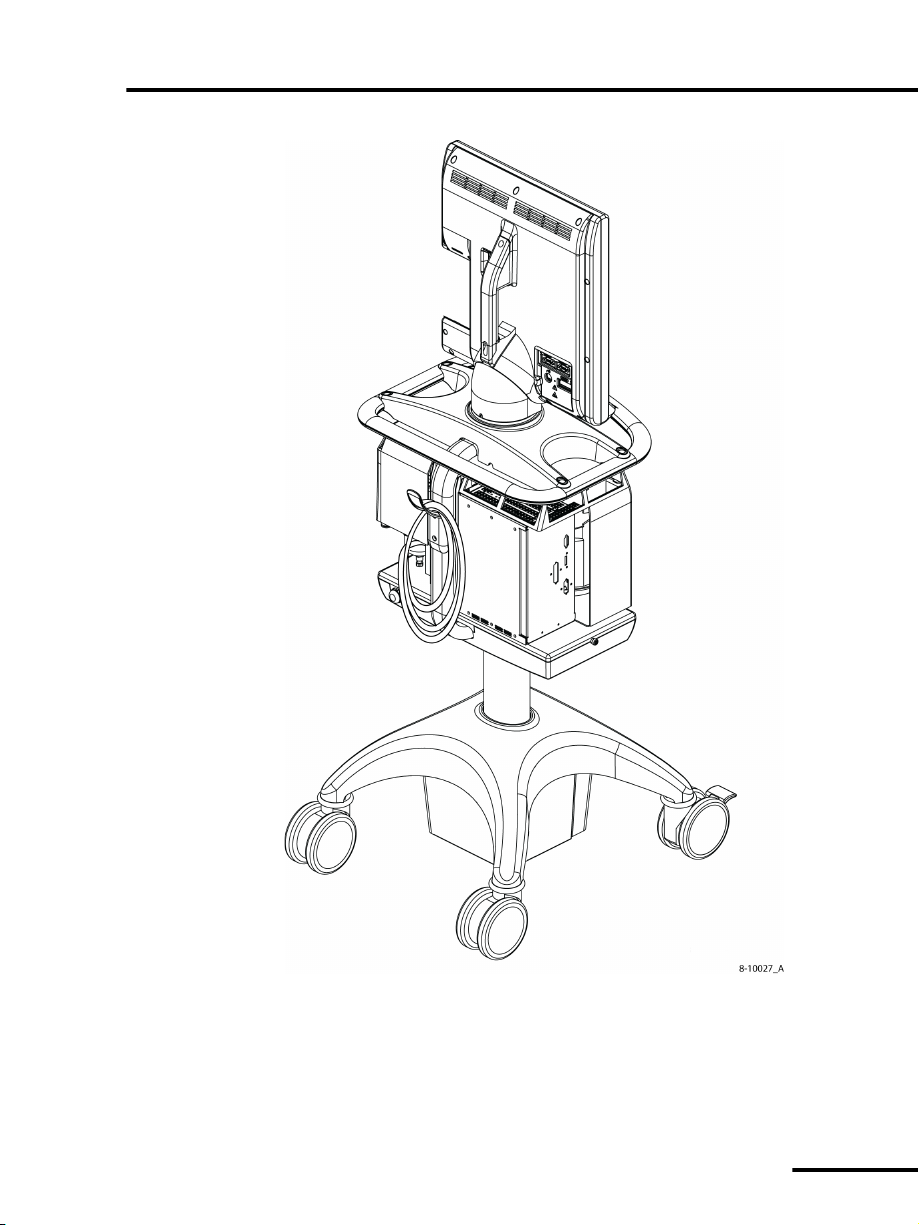
How to set up the Puritan Bennett 840 ventilator OP 2
Figure 2-5. Power cord storage on the newer Puritan Bennett 800
Series Ventilator Compressor Mount Cart and Puritan Bennett
800 Series Ventilator Pole Cart (shown)
Puritan Bennett 800 Series Ventilator System Operator’s Manual
OP 2-9
Page 70

OP 2 How to set up the Puritan Bennett 840 ventilator
Warning
Warning
2.2 How to connect the air and oxygen supplies
The Puritan Bennett 840 Ventilator System can use air and oxygen
from cylinder or wall supplies. Follow these steps to connect the
air and oxygen supplies:
1 Ensure the supply pressures are 35 to 100 psi
(241 to 690 kPa), and the hospital gas piping system complies
with ISO 7396:1987, Non-flammable Medical Gas Pipeline
Systems, or an equivalent standard. Gas hoses must meet the
requirements of EN 739:1998, Low-pressure Hose Assemblies
for use with Medical Gases, and NFPA 99:2002, Standard for
Healthcare Facilities.
Due to excessive restriction of certain hose assemblies
(listed in Table B-1), reduced ventilator performance may
result when oxygen or air supply pressures< 50 psi
(345 kPa) are employed.
2. Connect the supply hoses to the inlet connectors at the rear of
the ventilator (see Figure 2-6).
• Connect only air to the air inlet, and only oxygen to the
oxygen inlet. Do not attempt to switch air and oxygen or
connect any other gas.
• Always connect at least two gas sources to the ventilator
to ensure a constant gas supply is available to the
patient. There are three gas source connections: the
compressor, air inlet, and oxygen inlet.
• Do not use anti-static or electrically conductive hoses in
the ventilator breathing system.
• Use only gas supply hoses recommended by
Puritan Bennett. Other hoses may be restrictive and may
cause improper ventilator operation.
Puritan Bennett 800 Series Ventilator System Operator’s Manual
OP 2-10
Page 71

How to set up the Puritan Bennett 840 ventilator OP 2
Caution
NOTE:
To prevent damage to the ventilator, ensure the connections to the
air and oxygen supplies are clean and unlubricated, and there is
no water in the air or oxygen supply gas.
If you suspect water in the air supply gas, use an external wall air
water trap to prevent water damage to the ventilator or its
components.
When you connect a pressurized air or oxygen source, the
ventilator air and oxygen regulators have a maximum bleed rate
of 3 L/min, even when the ventilator is not in use. Always take this
bleed rate into account when calculating air and oxygen usage.
When the air and oxygen hoses are not in use, you can wrap them
around the hook on the back of the cart for convenient storage
(Figure 2-6).
Puritan Bennett 800 Series Ventilator System Operator’s Manual
OP 2-11
Page 72
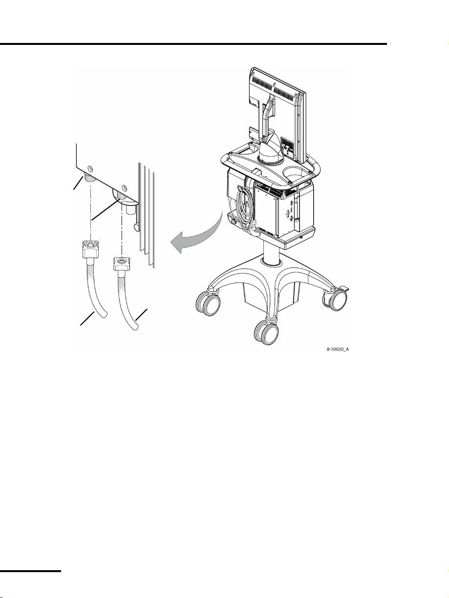
OP 2 How to set up the Puritan Bennett 840 ventilator
Oxygen
Oxygen hose
(from oxygen
Air hose
(from air
supply)
inlet
connector
Air inlet
connector
supply)
Figure 2-6. How to connect the air and oxygen supplies
Puritan Bennett 800 Series Ventilator System Operator’s Manual
OP 2-12
Page 73

How to set up the Puritan Bennett 840 ventilator OP 2
Warning
2.3 How to connect the patient circuit components
• To minimize the risk of bacterial contamination or
component damage, inspiratory and expiratory filters
must always be handled with care and connected to the
ventilator during use.
• To minimize the risk of patient injury, use only patient
circuits qualified for use in oxygen-enriched
environments with the Puritan Bennett 840 Ventilator
System. Do not use antistatic or electrically conductive
tubing in the ventilator breathing system. To ensure a
leak-tight connection, only use connectors and tubes
with ISO-standard cone and socket fittings (or use
adapters to connect barbed cuff fittings to ISO-standard
fittings).
• If you use an external, pneumatically-powered nebulizer
with the Puritan Bennett 840 Ventilator System, it adds
flow to the patient circuit and can adversely affect
spirometry, delivered O
breath triggering. Additionally, aerosolized particulates
in the ventilator circuit can lead to an increase in
exhalation filter resistance.
• Use one of the patient circuits listed in Appendix B to
ensure the maximum pressure/flow values specified by
IEC 60601-2-12:2001 are not exceeded (see Table A-11
on page OP A-18 for patient circuit testing
specifications). Using a circuit with a higher resistance
does not prevent ventilation, but can cause a short self
test (SST) fault or compromise the patient’s ability to
breathe through the circuit.
%, delivered tidal volumes, and
2
Puritan Bennett 800 Series Ventilator System Operator’s Manual
OP 2-13
Page 74

OP 2 How to set up the Puritan Bennett 840 ventilator
NOTE:
Warning
• Puritan Bennett recommends you run Short Self Test (SST)
every 15 days, between patients, and when you change the
patient circuit (particularly when you change circuit type, for
example, from adult to pediatric or neonatal).
• Puritan Bennett recognizes the protocol for running SST
varies widely among health care institutions.
Puritan Bennett does not specify or require specific
practices that will meet the needs of all institutions, nor is
Puritan Bennett responsible for the effectiveness of
institutional practices.
2.3.1 How to select and connect a patient circuit
Use low-compliance patient circuits to ensure optimum
compliance compensation, and use pediatric patient circuits
when the patient ideal body weight (IBW) is greater than 7 kg
(15 lb) but less than or equal to 24 kg (53 lb). Use the NeoMode
software option and neonatal patient circuits for patients whose
IBW is less than or equal to 7 kg.
For patients whose IBW is less than or equal to 24 kg, the
compliance compensation volume limit is four times the set tidal
volume, in addition to the set tidal volume. To avoid activating a
severe occlusion alarm, only use neonatal patient circuits with the
NeoMode software option.
Table 2-1 shows IBW values and patient circuit types. The
“Allowed but not recommended” ranges require an override.
Recommended ranges exist to ensure patient safety. Only
those with the expertise to judge the appropriate
circumstances should override the recommended ranges.
Puritan Bennett 800 Series Ventilator System Operator’s Manual
OP 2-14
Page 75

How to set up the Puritan Bennett 840 ventilator OP 2
Table 2-1: Patient circuit and IBW values
Recommendation Ideal body weight (IBW) in kg (lb)
Recommended Neonatal: 0.3-7.0 kg (0.66-15 lb)*
Pediatric: 7.0-24 kg (15-53 lb)
Adult: 25-150 kg (55-330 lb)
*Assumes NeoMode 2.0 software option is installed
Allowed but not
recommended
Neonatal: Not applicable
Pediatric: 3.5-6.5 kg (7.7-14.3 lb), and
25-35 kg (55-77 lb)
Adult: 7-24 kg (15-53 lb)
Figure 2-7 shows how to connect the patient circuit, including the
inspiratory filter, humidifier (if used), inspiratory limb, patient
wye, expiratory limb, collector vial, and expiratory filter.
Puritan Bennett 800 Series Ventilator System Operator’s Manual
OP 2-15
Page 76

OP 2 How to set up the Puritan Bennett 840 ventilator
Warning
(From patient)
Expiratory
Collector
vial
Expiratory limb
Patient wye
Inspiratory limb
Humidifier
Inspiratory
(To patient)
Tubing
filter
filter
of patient circuit
of patient circuit
Figure 2-7. How to connect the patient circuit
To ensure all patient circuit connections are leak-tight,
always perform a circuit leak test by running SST each time
you install the expiratory filter on the ventilator.
Puritan Bennett 800 Series Ventilator System Operator’s Manual
OP 2-16
Page 77

How to set up the Puritan Bennett 840 ventilator OP 2
Warning
Adding accessories to the ventilator can increase system
resistance. Ensure any changes to the recommended
ventilator circuit configurations do not exceed the specified
values for inspiratory and expiratory resistance
(Appendix A). If adding accessories to the patient circuit,
always run SST to measure circuit compliance before
beginning ventilation of the patient.
2.3.2 How to install the expiratory filter and collector vial
Install the expiratory filter and collector vial as follows:
1. Place the expiratory filter latch in the up position (see
Figure 2-8).
2. Slide the expiratory filter into the housing area with the
expiratory limb connection facing you.
3. Push the expiratory filter latch down; it will position the filter
properly.
4. Attach the expiratory limb of the patient circuit to the filter’s
expiratory limb connection.
If you do not use a drain bag, be sure to cap the collector vial drain
port on the expiratory filter (Figure 2-9).
Puritan Bennett 800 Series Ventilator System Operator’s Manual
OP 2-17
Page 78

OP 2 How to set up the Puritan Bennett 840 ventilator
1
2
3
4
5
6
Figure 2-8. How to install the expiratory filter and collector vial
Item Description
1 Pull latch up to install filter, pull down to hold filter and
collector vial in place
2 Slide the filter rim onto these tracks
3 Filter housing area
4 Expiratory filter
If you use a drain bag:
5 Expiratory limb connection (from patient)
6 Collector vial
1 Install the expiratory filter. (Refer to the instructions above.)
2 Install the clamp on the drain bag tubing, ensuring the clamp
is closed.
3 Uncap collector vial drain port at the base of the collector vial.
4 Connect the collector bag tubing to the vial drain port.
Puritan Bennett 800 Series Ventilator System Operator’s Manual
OP 2-18
Page 79

How to set up the Puritan Bennett 840 ventilator OP 2
Warning
Clamp
TubingDrain bag
Place the drain bag
The collector vial drain port
must be capped if you do not
use a drain bag
in the drawer of the RTA cart
or hang the drain bag on
the button provided on the side of the
cart
5 Connect the other end of tubing to drain bag.
6 If the ventilator is mounted on the cart, place the drain bag in
the cart drawer (if you have an older style ready-to-assemble
cart) or hang the drain bag on the button provided on the side
of the newer style Puritan Bennett 800 Series Ventilator
Compressor Mount Cart or Puritan Bennett 800 Series
Ventilator Pole Cart (Figure 2-9).
Do not attempt to clean, reprocess, or reuse the drain bag
as this poses the risk of infection to medical personnel and
the patient.
Figure 2-9. How to use the collector vial with or without the drain bag
Puritan Bennett 800 Series Ventilator System Operator’s Manual
OP 2-19
Page 80

OP 2 How to set up the Puritan Bennett 840 ventilator
NOTE:
Check the inspiratory and expiratory limbs of the
patient circuit, the collector vial, and the in-line
water traps regularly for water buildup. Under
certain conditions, they can fill quickly. Empty and
clean the collector vial and in-line water traps as
necessary.
Puritan Bennett 800 Series Ventilator System Operator’s Manual
OP 2-20
Page 81

How to set up the Puritan Bennett 840 ventilator OP 2
Flex arm
Threaded socket
(one of two)
2.3.3 How to install the flex arm
The flex arm supports the patient circuit between the ventilator
and the patient. Figure 2-10 and Figure 2-11 show how to install
the flex arm onto one of the two (in ready-to-assemble carts) or
four (in newer Puritan Bennett 800 Series Ventilator Compressor
Mount Cart or Puritan Bennett 800 Series Ventilator Pole Cart
threaded sockets on the ventilator cart.
Figure 2-10. How to install the flex arm on RTA cart
Puritan Bennett 800 Series Ventilator System Operator’s Manual
OP 2-21
Page 82

OP 2 How to set up the Puritan Bennett 840 ventilator
Caution
Flex arm
Threaded
socket
(one of four)
Figure 2-11. How to install the flex arm on the newer Puritan Bennett 800
Series Ventilator Compressor Mount Cart or Puritan Bennett 800 Series
Ventilator Pole Cart
Use only the cart handles to move the ventilator. Do not pull or
push the ventilator with the flex arm.
Puritan Bennett 800 Series Ventilator System Operator’s Manual
OP 2-22
Page 83

How to set up the Puritan Bennett 840 ventilator OP 2
Warning
Caution
Flex arm replacement parts can be found in the Purian Bennett 800
Series Ventilator Service Manual.
2.3.4 How to install the humidifier
An electrical outlet for a humidifier is located on the front of the
BDU. Figure 2-12 shows how to install a Fisher & Paykel
humidifier onto the ventilator for ventilators mounted on RTA
carts. Separate humidifier installation instructions are shipped
with humidifier mounting kits listed in Table B-2 and Table B-3 of
Appendix B for humidifiers mounted on Puritan Bennett 800
Series Ventilator Compressor Mount Carts and Puritan Bennett
800 Series Ventilator Pole Carts, respectively.
• When using a Fisher & Paykel humidifier with the Puritan
Bennett 840 Ventilator System, use the appropriate
Fisher & Paykel humidifier chambers for adult, pediatric,
and neonatal patients.
• Take proper precautions to prevent water/condensate
from splashing into the patient circuit during circuit
disconnects and high peak flow rate conditions.
• To avoid possible patient injury or damage to the
ventilator system, follow your institution’s protocol for
proper patient circuit condensate management.
• Qualified service personnel must first install the humidifier
mounting hardware.
• To avoid equipment damage to the ventilator due to liquid
ingress:
- Install the plug cover when the humidifier is plugged into the
ventilator.
- Install the flat cover plate over the humidifier electrical outlet on
the front of the BDU when the humidifier is not plugged into the
ventilator.
Puritan Bennett 800 Series Ventilator System Operator’s Manual
OP 2-23
Page 84

OP 2 How to set up the Puritan Bennett 840 ventilator
NOTE:
• To ensure uninterrupted ventilator operation, do not install a
humidifier whose maximum current capabilities exceed 2.3 A,
with a maximum power consumption of 270 VA.
• When you install a Fisher & Paykel humidifier, make sure the
humidifier has a right-angle electrical plug. A short power cord
is preferable.
• To ensure ventilator occlusion detection operates properly, do
not use Puritan Bennett Cascade humidifiers with the Puritan
Bennett 840 Ventilator System.
• If you have further questions about humidifiers qualified for
use with the Puritan Bennett 840 Ventilator System,
contact your representative.
• A humidifier connection is only available on 100 - 120 V
ventilators.
Puritan Bennett 800 Series Ventilator System Operator’s Manual
OP 2-24
Page 85

How to set up the Puritan Bennett 840 ventilator OP 2
Humidifier
Plug cover
BDU
Mounting
bracket on
front of
ventilator
Figure 2-12. How to install the humidifier
(Fisher & Paykel version shown) for ventilators mounted on RTA
carts
Puritan Bennett 800 Series Ventilator System Operator’s Manual
OP 2-25
Page 86

OP 2 How to set up the Puritan Bennett 840 ventilator
Warning
2.3.5 How to use the ventilator cart
Three optional carts are available for use with the Puritan Bennett
840 ventilator: the RTA (ready-to-assemble) cart, the Puritan
Bennett 800 Series Ventilator Compressor Mount Cart, and the
Puritan Bennett 800 Series Ventilator Pole Cart. The RTA cart can
be used with the 802 or 803 BPS, and newer Puritan Bennett 800
Series Ventilator Compressor Mount Cart can be used with a BPS
having a one-hour battery or an optional four-hour battery. The
Puritan Bennett 800 Series Ventilator Pole Cart also has a onehour or optional four-hour battery as part of its battery backup
system.
Install only ventilator BDUs with serial numbers starting
with 3512 onto the newer Puritan Bennett 800 Series
Ventilator Compressor Mount Cart and Puritan Bennett
800 Series Ventilator Pole Cart. Other ventilator serial
numbers are not compatible with the newer carts.
The Puritan Bennett 800 Series Ventilator Compressor Mount
Cart and the Puritan Bennett 800 Series Ventilator Pole Cart may
not be available in all regions. Please contact your local Puritan
Bennett representative for more information.
To locate the cart’s lot number, a label is applied underneath the
cart handle on the cart’s spine weldment (Figure 2-13).
Puritan Bennett 800 Series Ventilator System Operator’s Manual
OP 2-26
Page 87

How to set up the Puritan Bennett 840 ventilator OP 2
Warning
Warning
Lot number label
Figure 2-13. Location of cart lot number label
Lock the cart’s wheels prior to installing or removing
ventilator components.
Figure 2-14 and Figure 2-15 show how to lock and unlock the
cart’s front wheels.
To avoid interrupted ventilator operation or damage to
ventilator components, use the cart to move the ventilator.
Do not use the cables, the power cord, GUI, or patient
circuit components to push or pull the ventilator.
Puritan Bennett 800 Series Ventilator System Operator’s Manual
OP 2-27
Page 88

OP 2 How to set up the Puritan Bennett 840 ventilator
Press large tab
down to lock
Unlocked position Locked position
Press small tab
down to unlock
Lift up to unlock
Press down to lock
Unlocked position Locked position
Figure 2-14. How to lock and unlock the RTA cart’s front wheels
Figure 2-15. How to lock and unlock the Puritan Bennett 800
Series Ventilator Compressor Mount Cart or Puritan Bennett 800
Series Ventilator Pole Cart front wheels
Puritan Bennett 800 Series Ventilator System Operator’s Manual
OP 2-28
Page 89

CHAPTER
3 How to run Short Self Test (SST)
Chapter 3 tells you:
•When to run SST
• Required equipment for SST
• How to set up and run SST
• The SST tests and their functions
• How to understand the results of SST
3.1 Introduction to SST
SST uses an internal, programmed sequence of tests to:
• Verify proper function of the flow and pressure sensors
• Check the patient circuit for gas leaks
• Measure the expiratory filter resistance
• Measure patient circuit resistance
• Measure patient circuit compliance
3
SST requires approximately three minutes to complete.
Puritan Bennett 800 Series Ventilator System Operator’s Manual
OP 3-1
Page 90

OP 3 How to run Short Self Test (SST)
Warning
NOTE:
• Always disconnect the ventilator from the patient before
you run SST. If you run SST while the ventilator is
connected to the patient, physical injury to the patient
may occur.
• An ALERT reported by SST indicates the ventilator or a
related component has a defect. Repair the ventilator or
related component before you use the ventilator on a
patient, unless you can determine with certainty the defect
cannot create a hazard for the patient, or add to the risks
that may occur from other hazards.
• When you run SST, configure the patient circuit exactly as
it will be used on the patient (for example, with same
accessories). If you add accessories to the patient circuit
after you run SST, you must rerun SST with the new
accessories installed before you begin to ventilate the
patient.
3.2 When to run SST
Puritan Bennett recognizes health care institutions may have
their own ventilator protocols. However, Puritan Bennett is
not responsible for the effectiveness of any institution’s
protocols. Nor can Puritan Bennett specify, or require, specific
practices to meet the internal needs of every health care
institution.
Puritan Bennett 800 Series Ventilator System Operator’s Manual
OP 3-2
Page 91

How to run Short Self Test (SST) OP 3
Puritan Bennett recommends running SST when one or more of
the events below occurs:
• When you replace the patient circuit and the exhalation filter
after 15 days of use
• When you are ready to connect a new patient to the ventilator
• When you connect a different patient circuit to the ventilator
• When you install a new or sterilized expiratory filter
• When you change the patient circuit type
• When you change the humidification device type
• When you remove or add accessories to the patient circuit,
such as a humidifier, water trap, or drain bag
Use SST at any time, provided a patient is not attached to the
ventilator, to:
• Check the patient circuit for gas leaks
• Calculate patient circuit compliance and resistance
• Calculate expiratory filter resistance
After SST begins, the system prompts you to prepare the ventilator
to conduct certain tests. The system waits indefinitely at a prompt
until you take action and respond appropriately.
3.3 SST components and requirements
When you conduct SST, you must have available the components
and equipment you will use on the patient:
• Patient tubing
• Expiratory filter and collector vial
•Inspiratory filter
• Humidifier, as applicable
• Other accessories (e.g. water traps, drain bag), as applicable
Additional requirements include:
• A No. 1 rubber stopper to block the airway at the patient wye
Puritan Bennett 800 Series Ventilator System Operator’s Manual
OP 3-3
Page 92

OP 3 How to run Short Self Test (SST)
Caution
Warning
• Two gas sources (air and oxygen) connected to the ventilator
• Each gas source pressure must be between 35-100 psi
(241 to 690 kPa)
• To prevent SST failures due to leaks, ensure any circuit
components such as collector vial drain port cap (if not using a
drain bag), the seal between the expiratory filter and collector
vial, and water trap (if used) seals are properly installed.
• If you are using a drain bag, ensure the tubing is properly
installed on the collector vial drain port and the tubing is
clamped. If the drain bag tubing is not clamped during SST,
large leaks and large compliance values are possible which may
cause SST to report ALERTs or FAILURES.
Wait at least ten minutes after you turn on the ventilator before
you run SST. The warm up time of ten minutes will stabilize the
ventilator and ensure the accuracy of the SST tests.
3.4 SST Procedure
Always disconnect the ventilator from the patient before
you run SST. If you run SST while the ventilator is
connected to the patient, physical injury to the patient may
occur.
1 Turn the power switch (located on the front of the BDU). The
system conducts the POST (power-on self test) and displays
the Ventilator Startup screen.
2 Allow the ventilator to stabilize for ten minutes with the
power on.
3 Install the patient circuit, the expiratory and inspiratory filters
you will use to ventilate the patient.
Puritan Bennett 800 Series Ventilator System Operator’s Manual
OP 3-4
Page 93

How to run Short Self Test (SST) OP 3
Caution
NOTE:
The patient circuit must be unobstructed and properly connected
to the ventilator to ensure accurate circuit resistance
measurement.
4At the Ventilator Startup screen, touch the SST button (lower
touch screen), then press the
TEST button (on the left side of
the BDU) within five seconds. (Refer to Figure 3-1 for location
of
TEST button.)
The system displays the SST Setup screen (lower touch screen).
You must press the TEST button within five seconds of
touching the SST button or SST will not start.
Test button
Figure 3-1. Test button location
Puritan Bennett 800 Series Ventilator System Operator’s Manual
OP 3-5
Page 94

OP 3 How to run Short Self Test (SST)
Caution
Warning
Do not press the test button when powering up the ventilator. This
may cause the ventilator to enter Service Mode. If you enter
Service Mode, do not attempt to run Extended Self Test (EST) with
a patient circuit. Doing so will cause EST to fail. If EST fails, the
ventilator will remain in a Ventilator Inoperative state until EST
successfully passes.
If you accidentally enter Service Mode, exit Service Mode by
touching the EXIT button on the lower GUI screen and then
pressing the ACCEPT key.
5Touch the PATIENT CIRCUIT key in the lower touch screen,
then use the knob to select either Adult, Pediatric, or Neonatal
(if NeoMode software option is installed) patient circuit.
6Touch the
screen, then use the knob to select the humidification type
you will use for patient ventilation.
If you will not use a humidifier, set the humidification type to
HME.
7 Press
and humidification types.
HUMIDIFICATION TYPE key in the lower touch
ACCEPT to complete your selection of the patient circuit
Incorrectly specifying the patient circuit type or changing
the patient circuit type after you have run SST can affect
the accuracy of the compliance calculation, the measured
exhaled tidal volume, and delivered/measured inspired
tidal volumes. You must rerun SST when you change the
circuit type.
Compliance calculation and tidal volume accuracy may also
be affected by incorrectly specifying or changing the
humidifier after running SST. If you change humidifiers,
ensure you change the humidification type as described in
Section 4.8. For optimum accuracy, rerun SST using the
new humidifier.
Puritan Bennett 800 Series Ventilator System Operator’s Manual
OP 3-6
Page 95

How to run Short Self Test (SST) OP 3
Warning
Warning
8 The ventilator automatically starts the test sequence. Refer to
Table 3-1 for details regarding each SST test step.
The SST Flow Sensor, Expiratory Filter, Circuit Resistance, and
Compliance Calibration tests require your intervention. The
system will wait indefinitely for your response. Otherwise you
don’t need to do anything unless a test result is
FAILURE, or SST is complete.
ALERT or
9 As each test is performed, the SST Status screen shows test
results (see Table 3-2).
To ensure reliable SST results, do not repeat an individual
test with a different patient circuit if the test result is
FAILURE or ALERT. If you suspect a defective patient circuit,
replace the patient circuit and restart SST from the
beginning.
10 You can touch EXIT SST during SST to halt testing. You can
touch
EXIT SST again to resume testing, or press ACCEPT to
restart the ventilator (if SST has not detected an
FAILURE).
ALERT or
To ensure correct compensation for circuit resistance and
compliance, do not exit SST until the entire SST is
successfully completed. Do not begin normal ventilation
until the entire SST is successfully completed with the
correct patient circuit installed.
11 When all of the tests in SST are complete, the SST Status screen
displays all individual test results and SST outcome. Table 3-3
summarizes overall SST outcomes and how to proceed in each
case.
12 To begin normal ventilation (if SST has not detected an
or
FAILURE), touch EXIT SST, then press ACCEPT.
13 The ventilator reruns
POST.
Puritan Bennett 800 Series Ventilator System Operator’s Manual
ALERT
OP 3-7
Page 96

OP 3 How to run Short Self Test (SST)
Warning
14 The ventilator displays the Ventilator Startup screen. Proceed
with Ventilator S t a r t u p to configure the system for the patient.
Table 3-1: SST test sequence
Test step Function Comments
SST Setup The system prompts you to
specify the patient circuit
type and humidification type
you will use for patient
ventilation.
1 Specify the patient circuit
type.
2 Specify the humidification
type.
You can select one of three
humidification types:
• Heated expiratory tube
• Non-heated expiratory
tube
• HME (heat-moisture
exchanger)
3 For non-HME humidifiers,
specify the dry humidifier
volume. Use the specified
volume, not the
compressible volume, of
the humidifier.
4 Press the
Select the correct
patient circuit type
and humidification
type. Otherwise,
faulty occlusion
detection and
erroneous expiratory
spirometry can result.
ACCEPT key.
Puritan Bennett 800 Series Ventilator System Operator’s Manual
OP 3-8
Page 97

How to run Short Self Test (SST) OP 3
NOTE:
NOTE:
NOTE:
Table 3-1: SST test sequence
Test step Function Comments
The HUMIDIFIER VOLUME button is not visible on the touch screen if you select
HME.
SST Setup (cont) The system prompts you to
connect the patient circuit to
inspiratory filter.
Use Figure 2-6 on page OP
2-14 to connect the patient
circuit.
Do not run the Flow Sensor Test with a humidifier
installed, even if you will use a humidifier when you
begin patient ventilation.
The system prompts you to
block the patient wye.
The system checks the
accuracy of the inspiratory
and expiratory flow sensors.
After the test completes, the
system prompts you to
connect the humidifier.
If you will use a humidifier during patient ventilation, connect the humidifier
to the patient circuit after the system passes the SST Flow Sensor Test. Refer to
Figure 2-6 on page OP 2-14 for connection information.
1 Connect the patient circuit
to the inspiratory filter—
but without the
humidifier.
2 Press
3 Block the wye with a
4 Press
If the status of the SST Flow
Sensor Test is
cannot use the
function.
ACCEPT to begin
the test.
No. 1 stopper.
ACCEPT.
FAILURE, you
OVERRIDE
Circuit Pressure Test The system verifies proper
function of the BDU pressure
sensors.
Puritan Bennett 800 Series Ventilator System Operator’s Manual
If the status of the Circuit
Pressure Test is FAILURE, you
cannot use the
function.
OVERRIDE
OP 3-9
Page 98

OP 3 How to run Short Self Test (SST)
Table 3-1: SST test sequence
Test step Function Comments
Circuit Leak Test The system determines the
ability of the circuit to hold
pressure.
The system displays the drop
in circuit pressure over a
10 second interval.
Expiratory Filter
Resistance Test
The system prompts you to
detach circuit tubing from
the expiratory filter.
At the conclusion of the
Expiratory Filter Resistance
Tes t, the system displays the
pressure drop across the
expiratory filter.
If the system reports
and you choose to override
the alert status, the result can
be improper compliance
compensation, inaccurate
tidal volume delivery, or
autotriggering during patient
ventilation.
If the test detects excessive
leaks, the system reports a
FAILURE.
1 Detach the patient circuit
from the expiratory filter.
2 Press
If the system reports an
for the Expiratory Filter
Resistance Test and you
override the
inaccurate patient pressure
estimation can result.
The system will report a
FAILURE if the test detects an
exhalation compartment
occlusion or an expiratory
filter occlusion.
If you do not correctly follow
the prompts to disconnect
and connect the patient
circuit, the system will report a
FAILURE.
ACCEPT to begin
the test.
ALERT, an
ALERT
ALERT
The system prompts you to
reattach the patient circuit.
Puritan Bennett 800 Series Ventilator System Operator’s Manual
OP 3-10
3 Reattach the patient
circuit to the expiratory
filter.
4 Press
ACCEPT to begin
the next test.
Page 99

How to run Short Self Test (SST) OP 3
Table 3-1: SST test sequence
Test step Function Comments
Circuit Resistance The system prompts you to
unblock the patient wye.
The system displays the
pressure drop across the
inspiratory and expiratory
limbs.
The reported pressure drop
includes the effect of all
devices installed on each
limb, such as filters, water
traps, or a humidifier.
Compliance
Calibration
The system prompts you to
block the patient wye.
If you selected a
humidification type of either
Heated exp tube or Nonheated exp tube, the
ventilator prompts you to
indicate if there is water in
the humidifier.
1 Remove the stopper from
the wye.
2 Press ACCEPT to begin
the test.
If the system reports an
ALERT
for the pressure drop across
the two limbs and you
override the
ALERT, an
inaccurate patient pressure
estimation can result.
The system reports a
FAILURE
if the test detects excessive
high or low limb resistance, or
if you do not follow the
prompt to unblock the wye.
1 Block the wye with a
No. 1 stopper.
2 Press
ACCEPT to begin
the patient circuit
compliance test.
3 Press ACCEPT to indicate
YES or CLEAR to indicate
NO, as appropriate, to
indicate whether or not
there is water in the
humidifier.
Puritan Bennett 800 Series Ventilator System Operator’s Manual
OP 3-11
Page 100

OP 3 How to run Short Self Test (SST)
NOTE:
Table 3-1: SST test sequence
Test step Function Comments
Compliance
Calibration (cont)
3.5 SST Results
The Puritan Bennett™ 840 Ventilator System uses four status
categories to characterize the individual SST test results, and the
overall SST outcome.
ALERT
You can override an ALERT reported for an individual test if you
can determine with certainty the defect in the ventilator or
related component cannot create a hazard for the patient, or add
to the risks arising from other hazards.
The system displays the
compliance of the patient
circuit.
The system prompts you to
unblock the patient wye.
If the system reports an
for the patient circuit
compliance and you override
ALERT, improper
the
compliance compensation or
inaccurate tidal volume
delivery can result.
The system reports a
if the test detects an out-ofrange compliance condition.
4 Remove the stopper from
the patient wye.
5 Press
ACCEPT to
complete the SST test
sequence.
ALERT
FAILURE
If an ALERT is reported and you exit SST without overriding the
ALERT, the ventilator will enter the safety valve open (SVO)
state and cannot be used for normal ventilation until SST
passes or the ALERT is overridden.
Puritan Bennett 800 Series Ventilator System Operator’s Manual
OP 3-12
 Loading...