

Page 1
840
Ve nt i l at or Sys t e m
Service Manual
4-070496-00 Rev A
August, 2003
anual 4-070089-00 Rev. B (10/02)
Page 2

Page 3

Copyright information
Copyright 2003 Puritan-Bennett Corporation. All rights reserved. The 840TM Ventilator System is manufactured in
accordance with Puritan Bennett proprietary information, covered by one or more of the following U.S. Patents and
foreign equivalents: 4,954,799; 5,161,525; 5,271,389; 5,301,921; 5,319,540; 5,339,807; 5,368,019; and 5,390,666.
840, 800 Series, DualView, SandBox, SmartAlert, Flow-by, and are trademarks of Puritan-Bennett Corporation.
The information contained in this manual is the sole property of Puritan-Bennett Corporation and may not be
duplicated without permission. This manual may be revised or replaced by Puritan Bennett at any time and without
notice. You should ensure that you have the most current applicable version of this manual; if in doubt, contact the
Technical Support Department of Puritan-Bennett Corp. or your local representative. While the information set forth
herein is believed to be accurate, it is not a substitute for the exercise of professional judgment.
The ventilator should be operated and serviced only by trained professionals. Puritan Bennett’s sole responsibility
with respect to the ventilator, and its use, is as stated in the limited warranty provided.
Nothing in this manual shall limit or restrict in any way Puritan Bennett’s right to revise or otherwise change or
modify the equipment (including its software) described herein, without notice. In the absence of an express, written
agreement to the contrary, Puritan Bennett has no obligation to furnish any such revisions, changes, or
modifications to the owner or user of the equipment (including its software) described herein.
Manufacturer: Authorized Representative:
Puritan-Bennett Corporation Tyco Healthcare UK Limited
4280 Hacienda Drive 154 Fareham Road
Pleasanton, CA 94588-2719 Gosport
USA PO13 0AS
UK
Phone: +800.255.6774
Page 4

Preface
Definitions
This manual uses three special indicators to convey information of a specific nature.
They include:
Warning
Indicates a condition that can endanger the patient or the ventilator operator.
Caution
Indicates a condition that can damage the equipment.
NOTE:
Indicates points of particular interest that make operation of the ventilator more efficient or
convenient.
Warnings, cautions, and notes
Please take the time to familiarize yourself with the following caveats as they cover safety
considerations, special handling requirements, and regulations that govern the use of the 840
Ventilator System.
• To ensure proper servicing and avoid the possibility of physical injury, only qualified
personnel should attempt to service or make authorized modifications to the ventilator.
The user of this product shall have sole responsibility for any ventilator malfunction
due to operation or maintenance performed by anyone not trained by Puritan Bennett
staff.
• To avoid an electrical shock hazard while servicing the ventilator, be sure to remove all
power to the ventilator by disconnecting the power source and turning off all ventilator
power switches.
• To avoid a fire hazard, keep matches, lighted cigarettes, and all other sources of ignition
(e.g., flammable anesthetics and/or heaters) away from the 840 Ventilator System and
oxygen hoses.
Do not use oxygen hoses that are worn, frayed, or contaminated by combustible materials
such as grease or oils. (Textiles, oils, and other combustibles are easily ignited and burn
with great intensity in air enriched with oxygen.)
In case of fire or a burning smell, immediately disconnect the ventilator from the oxygen
supply, facility power, and BPS.
• When handling any part of the 840 Ventilator System, always follow your hospital
infection control guidelines for handling infectious material.
Puritan Bennett recognizes that cleaning, sterilization, sanitation, and disinfection
practices vary widely among healthcare institutions. It is not possible for Puritan Bennett
to specify or require specific practices that will meet all needs, or to be responsible for the
effectiveness of cleaning, sterilization, and other practices carried out in the patient care
setting.
i 4-070496-00 Rev. A (08/03) 840 Ventilator System Service Manual Rev. A (08/03)
Page 5

Preface
Puritan Bennett does recommend that users of its products that require cleaning and
sterilization/disinfection consider the National Standards and Recommended Practices for
Sterilization published by the Association for the Advancement of Medical
Instrumentation (AAMI), as well as the following Center for Disease Control (CDC)
publications: Guidelines for Maintenance of In-use Respiratory Therapy Equipment and
Guidelines for Prevention of Nosocomial Pneumonia.
• Patients on life-support equipment should be appropriately monitored by competent
medical personnel and suitable monitoring devices.
•The 840 Ventilator System is not intended to be a comprehensive monitoring device and
does not activate alarms for all types of dangerous conditions for patients on life-support
equipment.
• For a thorough understanding of ventilator operations, be sure to thoroughly read the 840
Ventilator System Operator's and Technical Reference Manual before attempting to use the
system.
• Before activating any part of the ventilator, be sure to check the equipment for proper
operation and, if appropriate, run SST (Short Self Test).
• Do not use sharp objects to make selections on the graphical user interface (GUI) display
or keyboard.
• Federal law (U.S.) restricts the sale of this device to, or by the order of, any physician.
• Check the ventilator periodically as outlined in this manual; do not use if defective.
Immediately replace parts that are broken, missing, obviously worn, distorted, or
contaminated.
• An alternative source of ventilation should always be available when using the 840
Ventilator System.
•The 840 Ventilator System is a member of the 800 Series™ family of products. Any
accessory whose model number is 80x (for example, the 802 Backup Power Source or 806
Compressor Unit) operates with all 800 Series ventilators. An accessory whose model
number is 84x operates only with a model 840 Ventilator System.
Year of man ufact ure
The year of manufacture for ventilators whose serial numbers begin with 4200 is indicated on
the rear panel of the BDU as shown here. The two digit number following the year indicates
the month of manufacture.
2003 – 10
For ventilators whose serial numbers begin with 3510, the year of manufacture is indicated by
the serial number’s 5th and 6th digits. In the example below, a ventilator with serial number
3510021223 was the 1223rd unit built in 2002.
3510 02 1223
Sequential number
Year of manufacture
840 Ventilator System Service Manual 4-070496-00 Rev. A (08/03) ii
Page 6

Preface
Electromagnetic susceptibility
The 840 Ventilator System complies with the requirements of IEC 601-1-2 (EMC Collateral
Standard), including the E-field susceptibility requirements at a level of 10 volts per meter, at
frequencies from 26 MHz to 1 GHz, and the ESD requirements of this standard. However, even at
this level of device immunity, certain transmitting devices (cellular phones, walkie-talkies,
cordless phones, paging transmitters, etc.) emit radio frequencies that could interrupt
ventilator operation if located in a range too close to the ventilator. It is difficult to determine
when the field strength of these devices becomes excessive. Practitioners should be aware that
radio frequency emissions are additive, and that the ventilator must be located a sufficient
distance from transmitting devices to avoid interruption. Do not operate the ventilator in a
magnetic resonance imaging (MRI) environment. Section 7 describes possible ventilator
alarms and what to do if they occur. Consult with your institution’s biomedical engineering
department in case of interrupted ventilator operation and before relocating any life support
equipment.
Customer assistance
For further assistance contact Puritan-Bennett Corporation at 1.800.255.6774 or your local
Puritan Bennett representative.
About this manual
This manual provides information needed to service the Puritan Bennett 840 Ventilator
System. This manual is intended for use by certified biomedical engineering technicians or
personnel with equivalent experience and training in servicing this type of equipment. It is
recommended that the user complete the Puritan Bennett training class geared specifically to
the 840 Ventilator System.
While this manual covers the ventilator configurations currently supported by Puritan
Bennett, it may not be all-inclusive and may not be applicable to your ventilator. Within the
USA, contact Puritan Bennett at 1.800.255.6774 for questions regarding the applicability of
the information.
iii 4-070496-00 Rev. A (08/03) 840 Ventilator System Service Manual Rev. A (08/03)
Page 7

1 General information
1.1 How to use this manual...............................................................................................1-1
1.2 General product description ........................................................................................1-1
1.3 Configuration information...........................................................................................1-2
1.4 Accessories ..................................................................................................................1-2
1.5 Specifications ..............................................................................................................1-3
1.6 Compliance and approvals ..........................................................................................1-7
1.7 Technical information..................................................................................................1-8
1.8 Range, resolution, accuracy, and new patient/default settings ..................................1-10
1.9 Tools, equipment, and service materials ....................................................................1-19
1.10 Periodic maintenance ..............................................................................................1-22
1.11 Service kits ..............................................................................................................1-24
1.12 Controls and indicators .........................................................................................1-24
1.13 Onscreen symbols and abbreviations.......................................................................1-41
1.14 Ventilator serial numbers and software version ........................................................1-41
1.15 Service philosophy...................................................................................................1-41
SECTION
CONTENTS
2 Theory of operation
2.1 Major ventilator subassemblies ....................................................................................2-1
2.1.1 Breath delivery unit (BDU)................................................................................... 2-2
2.1.2 Graphic user interface (GUI) ................................................................................2-2
2.1.3 806 Compressor Unit ..........................................................................................2-3
2.1.4 802 Backup Power Source (BPS)..........................................................................2-4
2.1.5 Cart.....................................................................................................................2-4
2.1.6 Patient system .....................................................................................................2-5
2.2 Operational overview ..................................................................................................2-6
2.3 Pneumatic system ....................................................................................................... 2-9
2.3.1 Inspiratory module ............................................................................................2-14
2.3.1.1 Gas supply conditioning subsystem.........................................................2-15
2.3.1.2 Flow control subsystem ........................................................................... 2-20
2.3.1.3 Safety valve and inspiration monitoring subsystem..................................2-23
2.3.1.4 Inspiratory module operation ..................................................................2-28
2.3.2 Patient System................................................................................................... 2-31
2.3.2.1 Patient system components.....................................................................2-32
2.3.2.2 Patient system operation .........................................................................2-33
2.3.3 Exhalation module.............................................................................................2-33
2.3.3.1 Exhalation module components ..............................................................2-34
2.3.3.2 Exhalation module operation...................................................................2-35
840 Ventilator System Service Manual 4-070496-00 Rev. A (08/03)
vii
Page 8

Contents
2.3.4 806 Compressor Unit........................................................................................ 2-38
2.3.4.1 806 Compressor unit components .......................................................... 2-38
2.3.4.2 806 Compressor unit operation............................................................... 2-41
2.4.1 Summary of electrical components ................................................................... 2-42
2.4.2 Overview of electrical system operation ............................................................ 2-47
2.4.3 ac distribution components............................................................................... 2-50
2.4.3.1 Power cord ............................................................................................. 2-50
2.4.3.2 ac panel .................................................................................................. 2-50
2.4.3.3 Power switch........................................................................................... 2-53
2.4.4 Power supply .................................................................................................... 2-54
2.4.5 BPS ................................................................................................................... 2-56
2.4.6 Card Cage ........................................................................................................ 2-58
2.4.6.1 Motherboard PCB ................................................................................... 2-60
2.4.6.2 BDU CPU PCB ......................................................................................... 2-63
2.4.6.3 Analog interface (AI) PCB ........................................................................ 2-67
2.4.7 Data key subsystem .......................................................................................... 2-69
2.4.8 GUI................................................................................................................... 2-69
2.4.8.1 GUI CPU PCB ......................................................................................... 2-69
2.4.8.2 Touch frame PCB .................................................................................... 2-75
2.4.8.3 Keyboard assembly with knob................................................................. 2-76
2.4.8.4 GUI LED PCB........................................................................................... 2-78
2.4.8.5Backlight inverter PCB and LCD lamps ........................................................ 2-79
2.4.8.6 GUI alarm assembly ................................................................................ 2-80
2.4.9 BDU LED PCB ................................................................................................... 2-81
2.4.10 Inspiratory electronics PCB.............................................................................. 2-81
2.4.11 Exhalation transducer PCB .............................................................................. 2-83
2.4.11.1BD (continuous-tone) alarm assembly....................................................... 2-85
2.4.12 806 Compressor unit ...................................................................................... 2-85
2.4.12.1806 compressor unit ac power distribution components and motor.......... 2-86
2.4.12.2 806 compressor PCB............................................................................... 2-86
2.4.12.3806 Compressor unit operation ................................................................ 2-90
2.5 Breath delivery.......................................................................................................... 2-92
2.5.1 Inspiration......................................................................................................... 2-92
2.5.1.1Pressure triggering...................................................................................... 2-94
2.5.1.2 Flow triggering ....................................................................................... 2-94
2.5.1.3 Time-cycling method .............................................................................. 2-94
2.5.1.4 Operator triggering................................................................................. 2-94
2.5.2 Exhalation......................................................................................................... 2-94
2.5.2.1Time-cycling method.................................................................................. 2-95
2.5.2.2 End-inspiratory flow method................................................................... 2-95
2.5.2.3 Airway pressure method.......................................................................... 2-95
2.5.2.4 Time limit................................................................................................ 2-95
2.5.2.5 High circuit pressure limit........................................................................ 2-95
2.5.2.6 High ventilator pressure limit .................................................................. 2-95
viii 4-070496-00 Rev. A (08/03) 840 Ventilator System Service Manual
Page 9

3Self tests
Contents
2.6 Other hardware operations ....................................................................................... 2-97
2.6.1 Gas supply and control......................................................................................2-97
2.6.2 Data monitoring................................................................................................2-97
2.6.3 Pressure transducer autozero.............................................................................2-98
2.6.4 Power monitoring and power fail handling...................................................... 2-100
2.6.4.1 Loss of power source ............................................................................. 2-100
2.6.4.2 Supply voltage monitoring ....................................................................2-101
2.7.1 Safety valve open (SVO) state..........................................................................2-101
2.7.2 Occlusion handling .........................................................................................2-103
2.7.2.1 When the ventilator declares an occlusion .............................................2-103
2.7.2.2 Occlusion detection and handling .........................................................2-103
3.1 Introduction ................................................................................................................3-1
3.2 How to enter Service Mode .........................................................................................3-1
3.3 Self tests and background checks ................................................................................3-1
3.3.1 POST...................................................................................................................3-1
3.3.2 SST......................................................................................................................3-1
3.3.3 EST .....................................................................................................................3-2
3.3.4 Background checks.............................................................................................. 3-2
3.3.5 When self tests are run ........................................................................................ 3-2
3.4 Power on self test (POST) ............................................................................................3-3
3.4.1 Safety .................................................................................................................3-7
3.4.2 POST characteristics ............................................................................................3-7
3.4.3 POST following power interruptions....................................................................3-8
3.4.4 POST user interface .............................................................................................3-8
3.4.5 Structure of POST................................................................................................3-9
3.5 SST (short self test)....................................................................................................3-11
3.5.1 When to run......................................................................................................3-11
3.5.2 Hardware requirements .....................................................................................3-12
3.5.3 Running SST......................................................................................................3-13
3.6 EST (extended self test) .............................................................................................3-17
3.6.1 Description........................................................................................................3-17
3.6.2 When to run......................................................................................................3-17
3.6.3 Hardware requirements .....................................................................................3-18
3.6.4 Running EST......................................................................................................3-18
4 Service mode
4.1 Accessing service mode ...............................................................................................4-1
4.2 Service mode functions ...............................................................................................4-3
4.2.1 SST RESULT: Displaying SST results......................................................................4-5
4.2.2 DIAG LOG: Displaying error and status logs.........................................................4-5
4.2.3 Alarm log: Displaying the alarm history ............................................................... 4-7
4.2.4 VENT CONFIG: Displaying software revisions and serial numbers ........................4-7
4.2.5 OPERATION TIME: Displaying ventilator and compressor elapsed hours .............. 4-7
4.2.6 TEST SUMMARY: Displaying results from EST and SST .........................................4-7
4.2.7 EST: Extended self test.........................................................................................4-7
4.2.8 DATE/TIME: Adjusting date and time...................................................................4-7
4.2.9 EXIT: Exiting service mode...................................................................................4-7
840 Ventilator System Service Manual 4-070496-00 Rev. A (08/03) ix
Page 10

Contents
4.2.10 Other screens.................................................................................................... 4-8
4.2.11 Service Mode Setup .......................................................................................... 4-8
4.2.12 External Test Control: Performing remote ventilator testing .............................. 4-8
4.2.13 Exp Valve Calibration ........................................................................................ 4-9
4.2.13.1 Running Exp Valve Calibration .................................................................. 4-9
4.2.14 Vent Inop Test ............................................................................................... 4-11
4.2.14.1 Running the Vent Inop Test..................................................................... 4-11
4.2.14.2 Flow Sensor Calibration........................................................................... 4-12
4.2.15 Running Flow Sensor Calibration .................................................................... 4-13
4.2.15.1 Atmospheric Pressure Transducer ............................................................ 4-13
4.2.16 Automatically executed service mode functions .............................................. 4-14
4.2.16.1 Initialize Flow Sensor............................................................................... 4-14
4.2.16.2 Cal Info Duplication ................................................................................ 4-14
4.2.17 Serial number setup ....................................................................................... 4-15
4.2.17.1 Running Serial Number Setup ................................................................. 4-15
4.2.18 Datakey Update .............................................................................................. 4-16
4.2.19 Serial Loopback Test ....................................................................................... 4-17
5 Performance verification
5.1 Tools, test equipment, and service materials ............................................................... 5-1
5.2 When to run ............................................................................................................... 5-1
5.3 Preliminary ventilator cleaning and inspection ............................................................ 5-4
5.4 Preliminary ventilator setup......................................................................................... 5-5
5.5 Preliminary calibrations and tests ................................................................................ 5-5
5.6 Performance verification guidelines............................................................................. 5-7
5.7 Performance verification tests...................................................................................... 5-7
5.7.1 Electrical safety test ............................................................................................ 5-8
5.7.2 Ground isolation check ....................................................................................... 5-8
5.7.3 Extended self test (EST)....................................................................................... 5-9
5.7.4 Regulator setting verification............................................................................... 5-9
5.7.5 Serial loopback test (10.4-inch GUI only) .......................................................... 5-10
5.7.6 Performance verification using PTS 2000 Performance
Test System and BreathLab 840 VTS software ................................................... 5-10
5.7.7 Manual ventilator check using equipment other than
PTS 2000 Performance Test System................................................................... 5-10
6 Diagnostic codes
6.1 Introduction................................................................................................................ 6-1
6.2 Reference Tables ......................................................................................................... 6-1
6.3 Troubleshooting.......................................................................................................... 6-2
6.4 POST fault handling ................................................................................................... 6-2
6.5 Diagnostic CPU LED arrays.......................................................................................... 6-3
6.6 Diagnostic codes......................................................................................................... 6-4
6.6.1 How to interpret diagnostic codes ...................................................................... 6-4
6.7 Organization of diagnostic codes table ....................................................................... 6-5
6.8 System Diagnostic Log and BDU POST analog devices test ....................................... 6-54
x 4-070496-00 Rev. A (08/03) 840 Ventilator System Service Manual
Page 11

6.9 Diagnostic codes for POST faults ...............................................................................6-55
6.9.1 POST interrupt errors and test failures ...............................................................6-64
6.10 SST and EST test sequences and diagnostic codes.................................................... 6-66
6.10.1 How to troubleshoot LCD inverter PCB faults (UT0002).................................6-102
7 Alarm handling
7.1 Alarm classifications.....................................................................................................7-1
7.2 Responding to alarms..................................................................................................7-2
8 Service and repair
8.1 How to use this section................................................................................................8-1
8.2 General repair safety....................................................................................................8-1
8.3 General repair guidelines.............................................................................................8-2
8.4 Repair-related cleaning................................................................................................ 8-2
8.5 Electrical cables and pneumatic tubing........................................................................8-3
8.6 Adhesive use................................................................................................................8-3
8.7 Leak testing.................................................................................................................8-3
8.8 Electrostatic discharge control .....................................................................................8-4
8.8.1 ESD procedures and precautions .........................................................................8-4
8.9 Replacement part ordering.......................................................................................... 8-4
8.10 Testing, calibration, and other post-service procedures..............................................8-4
8.11 Patient system and accessories...................................................................................8-6
8.12 Graphic user interface (GUI) ......................................................................................8-6
8.13 Repairing the 10.4-inch GUI ......................................................................................8-8
8.13.1 Removing or installing the 10.4-inch GUI ..........................................................8-8
8.13.2 Removing the 10.4-inch GUI cable assembly .....................................................8-9
8.13.3 Replacing the 10.4-inch GUI cable assembly......................................................8-9
8.13.4 Removing 10.4-inch GUI rear housing...............................................................8-9
8.13.5 Replacing 10.4-inch GUI rear housing .............................................................8-10
8.13.6 Removing the 10.4-inch CPU shield ................................................................8-11
8.13.7 Removing the 10.4-inch GUI backlight inverter PCBs.......................................8-11
8.13.8 Removing the 10.4-inch GUI CPU PCB ............................................................ 8-12
8.13.9 10.4-inch GUI support bracket ........................................................................8-14
8.13.9.1 Removing the 10.4-inch GUI support bracket..........................................8-14
8.13.10 10.4-inch LCD panels ...................................................................................8-15
8.13.10.1Removing the 10.4-inch LCD panels........................................................8-15
8.13.11 10.4-inch touchframe PCB (MKG Touch)...................................................... 8-15
8.13.11.1Removing the 10.4-inch touchframe PCB................................................8-15
8.13.12 Replacing the 10.4-inch touchframe PCB.......................................................8-16
8.13.13 10.4-inch GUI LED PCB .................................................................................8-16
8.13.13.1Removing the 10.4-inch GUI LED PCB..................................................... 8-16
8.13.13.2Replacing the 10.4-inch GUI LED PCB .....................................................8-16
8.13.14 10.4-inch GUI alarm assembly.......................................................................8-17
8.13.14.1Removing the 10.4-inch GUI alarm assembly...........................................8-17
8.13.14.2Replacing the 10.4-inch GUI alarm assembly...........................................8-17
8.13.15 10.4-inch GUI keyboard assembly .................................................................8-18
8.13.15.1Replacing the 10.4-inch GUI keyboard assembly .....................................8-18
Contents
840 Ventilator System Service Manual 4-070496-00 Rev. A (08/03) xi
Page 12

Contents
8.13.16 10.4-inch GUI front housing ......................................................................... 8-18
8.13.16.1Replacing the 10.4-inch front housing .................................................... 8-18
8.13.17 10.4-inch rotor housing ................................................................................ 8-19
8.13.17.1Replacing the 10.4-inch rotor housing.................................................... 8-19
8.14 Repairing the 9.4-inch GUI...................................................................................... 8-20
8.14.1 Removing the 9.4-inch GUI touch screen bezel............................................... 8-20
8.14.2 9.4-inch GUI window...................................................................................... 8-21
8.14.3 Installing the 9.4-inch bezel ............................................................................ 8-22
8.14.4 The 9.4-inch keyboard assembly ..................................................................... 8-22
8.14.4.1 Removing 9.4-inch keyboard assembly.................................................... 8-22
8.14.4.2 Installing the 9.4-inch keyboard assembly ............................................... 8-24
8.14.5 Removing or installing the 9.4-inch GUI.......................................................... 8-24
8.14.6 9.4-inch GUI rear housing............................................................................... 8-25
8.14.6.1 Removing 9.4-inch GUI rear housing....................................................... 8-25
8.14.6.2 Installing 9.4-inch GUI rear housing ........................................................ 8-26
8.14.7 9.4-inch GUI alarm assembly .......................................................................... 8-27
8.14.7.1 Removing 9.4-inch GUI alarm assembly .................................................. 8-27
8.14.7.2 Installing 9.4-inch GUI alarm assembly.................................................... 8-28
8.14.8 9.4-inch GUI backlight inverter PCB and GUI LED PCB.................................... 8-28
8.14.8.1 Removing 9.4-inch GUI backlight inverter PCB........................................ 8-28
8.14.8.2Installing 9.4-inch GUI backlight inverter PCB ........................................... 8-29
8.14.8.3 Removing 9.4-inch GUI LED PCB............................................................. 8-29
8.14.8.4 Installing 9.4-inch GUI LED PCB .............................................................. 8-29
8.14.9 GUI EMI shield ................................................................................................ 8-30
8.14.9.1 Removing the GUI EMI shield.................................................................. 8-30
8.14.9.2 Installing the 9.4-inch GUI EMI shield...................................................... 8-30
8.14.10 9.4-inch video controller and VGA LCD controller PCBs ................................ 8-30
8.14.10.1Removing 9.4-inch VGA LCD controller PCBs (older CPU PCB)................ 8-31
8.14.10.2Installing 9.4-inch VGA LCD controller PCBs (older CPU PCB)................. 8-31
8.14.11 9.4-inch GUI CPU PCB .................................................................................. 8-32
8.14.11.1Removing the 9.4-inch GUI CPU PCB...................................................... 8-32
8.14.11.2Installing the 9.4-inch GUI CPU PCB ....................................................... 8-32
8.14.12 9.4-inch touchframe PCB (Carroll Touch)...................................................... 8-33
8.14.12.1Removing the 9.4-inch touchframe PCB.................................................. 8-33
8.14.12.2Reinstalling the 9.4-inch touchframe PCB................................................ 8-34
8.14.13 9.4-inch backlight panels and LCD panels .................................................... 8-36
8.14.13.1Removing a 9.4-inch backlight panel and LCD pane............................... 8-36
8.14.13.2Reinstalling a backlight panel and LCD panel .......................................... 8-36
8.14.14 9.4-inch GUI cooling vent filters.................................................................... 8-38
8.14.15 9.4-inch rotor housing .................................................................................. 8-39
8.14.15.1Removing the 9.4-inch rotor housing...................................................... 8-39
8.14.15.2Installing the 9.4-inch rotor housing ....................................................... 8-39
8.15 Breath delivery unit (BDU) ...................................................................................... 8-40
8.15.1 Removing BDU ............................................................................................... 8-43
8.15.2 BDU power cord and retainer.......................................................................... 8-44
8.15.3 Installing BDU................................................................................................. 8-44
8.15.4 Analog interface (AI) PCB and breath delivery (BD) CPU PCB .......................... 8-45
8.15.4.1 Removing AI PCB or BD CPU PCB ........................................................... 8-46
8.15.4.2 Installing AI PCB or BD CPU PCB ............................................................. 8-47
xii 4-070496-00 Rev. A (08/03) 840 Ventilator System Service Manual
Page 13

Contents
8.15.5 Power supply assembly....................................................................................8-48
8.15.5.1 Removing power supply assembly ...........................................................8-48
8.15.5.2 Installing power supply assembly.............................................................8-48
8.15.6 Power switch (S1)............................................................................................8-49
8.15.6.1 Removing power switch (S1)...................................................................8-49
8.15.6.2 Installing power switch (S1).....................................................................8-49
8.15.7 Humidifier receptacle (100 – 120 V models only) ............................................8-50
8.15.7.1 Removing humidifier receptacle...............................................................8-50
8.15.7.2 Installing humidifier receptacle ................................................................8-50
8.15.7.3 ac panel...................................................................................................8-51
8.15.8 Inspiratory module ..........................................................................................8-52
8.15.8.1 Inspiratory module modifications.............................................................8-52
8.15.8.2 Additional noise suppression (ferrite cores)..............................................8-52
8.15.8.3 Inspiratory module O-rings......................................................................8-53
8.15.8.4 Air inlet filter (F2).....................................................................................8-53
8.15.8.5 Fascia panel.............................................................................................8-54
8.15.8.6 Oxygen and air pressure switches (PS1 and PS2) .....................................8-56
8.15.8.7 PSOL cartridge ........................................................................................ 8-57
8.15.8.8 Removing inspiratory module..................................................................8-58
8.15.8.9 Leak testing inspiratory module ............................................................... 8-58
8.15.8.10Installing inspiratory module ...................................................................8-59
8.15.8.11Oxygen sensor (OS) ................................................................................ 8-59
8.15.8.12Inspiratory check valve (CV3) ..................................................................8-62
8.15.8.13Right-side plate .......................................................................................8-62
8.15.8.14Inspiratory electronics PCB ...................................................................... 8-64
8.15.8.15Left-side plate..........................................................................................8-64
8.15.8.16PSOL manifold ........................................................................................8-65
8.15.8.17Oxygen and air flow sensors (Q1 and Q2)...............................................8-67
8.15.8.18Safety valve .............................................................................................8-68
8.15.8.19Check valve assembly, regulator assembly, and flow sensor manifold ......8-70
8.15.8.20Oxygen and air regulators (REG1 and REG2) ........................................... 8-72
8.15.8.21Inspiratory pressure transducer autozero solenoid (SOL1)........................8-73
8.15.8.22Inspiratory floor assembly........................................................................8-73
8.15.9 Exhalation module...........................................................................................8-74
8.15.9.1 Exhalation collector vial (ECV) and expiratory filter (F9)...........................8-74
8.15.9.2 Removing exhalation module cover......................................................... 8-74
8.15.9.3 Removing exhalation module ..................................................................8-76
8.15.9.4 Installing exhalation module....................................................................8-76
8.15.9.5 Exhalation valve (EV) ...............................................................................8-77
8.15.9.6 Exhalation flow sensor (Q3).....................................................................8-80
8.15.9.7 Exhalation transducer PCB....................................................................... 8-81
8.15.9.8 Expiratory pressure transducer autozero solenoid (SOL2).........................8-82
8.15.9.9 Exhalation heater (EXH HTR) and check valve (CV5) ................................8-83
8.15.10 BDU housing................................................................................................. 8-84
8.15.10.1Removing BDU housing...........................................................................8-84
8.15.10.2Installing BDU housing............................................................................8-86
8.15.10.3Motherboard PCB ...................................................................................8-86
8.15.10.4BDU alarm assembly................................................................................8-87
840 Ventilator System Service Manual 4-070496-00 Rev. A (08/03) xiii
Page 14

Contents
8.15.11 Power indicator............................................................................................. 8-88
8.15.11.1Removing power indicator...................................................................... 8-88
8.15.11.2Installing power indicator........................................................................ 8-89
8.15.11.3Alarm blindmate cable............................................................................ 8-89
8.15.11.4Inspiratory blindmate cable..................................................................... 8-90
8.15.11.5dc power supply blindmate cable ........................................................... 8-91
8.15.11.6ac power supply blindmate harness ........................................................ 8-92
8.15.12 Release handle .............................................................................................. 8-94
8.15.12.1Removing release handle ........................................................................ 8-94
8.15.12.2Installing release handle.......................................................................... 8-94
8.16 806 compressor unit............................................................................................... 8-94
8.17 Servicing the 806 compressor ................................................................................. 8-95
8.17.1 Compressor inlet filter..................................................................................... 8-95
8.17.2 Removing and installing the compressor inlet filter ......................................... 8-95
8.17.3 Removing compressor from cart ..................................................................... 8-95
8.17.3.1 Disconnecting compressor from BDU...................................................... 8-95
8.17.3.2 Removing compressor from cart.............................................................. 8-96
8.17.4 Removing top cover........................................................................................ 8-96
8.17.5 Installing top cover ......................................................................................... 8-97
8.17.6 Cooling fans.................................................................................................... 8-97
8.17.6.1 Removing a cooling fan........................................................................... 8-97
8.17.6.2 Installing a fan......................................................................................... 8-98
8.17.7 Removing the back panel................................................................................ 8-98
8.17.8 Reinstalling the back panel.............................................................................. 8-98
8.17.9 Replacing an accumulator fitting and O-ring................................................... 8-99
8.17.10 Pneumatic hoses ........................................................................................... 8-99
8.17.11 Plenum assembly ........................................................................................ 8-100
8.17.11.1Removing the plenum assembly............................................................ 8-101
8.17.12 Heat exchanger (HE)................................................................................... 8-102
8.17.12.1Replacing the heat exchanger............................................................... 8-102
8.17.13 Removing and replacing the ac power cord................................................ 8-102
8.17.14 Removing and replacing the data cable ...................................................... 8-102
8.17.15 Compressor PCB ......................................................................................... 8-103
8.17.15.1Removing and replacing the compressor PCB ....................................... 8-103
8.17.16 Air dryer (dryer) and solenoid valve assembly.............................................. 8-103
8.17.16.1Removing and reinstalling the air dryer
and solenoid valve assembly and replacing filters8-104
8.17.17 Compressor assembly ................................................................................. 8-105
8.17.17.1Removing the compressor assembly...................................................... 8-105
8.17.17.2Replacing the coalescing filter element ................................................. 8-106
8.17.18 Replacing the compressor panels ................................................................ 8-107
8.17.19 Reinstalling the plenum assembly................................................................ 8-108
8.17.20 Reconnecting electrical cables.................................................................... 8-108
8.17.21 Replacing the Tinnerman clips .................................................................... 8-108
8.17.22 Reinstalling the back panel/accumulator assembly...................................... 8-108
8.17.23 Replacing the main inlet filter and reinstalling the top................................. 8-109
8.17.24 Reinstalling the compressor module............................................................ 8-109
8.17.25 Running performance verification test......................................................... 8-109
xiv 4-070496-00 Rev. A (08/03) 840 Ventilator System Service Manual
Page 15

9 Parts list
Contents
8.18 Backup power source (BPS) ................................................................................... 8-110
8.18.1 Removing BPS ...............................................................................................8-110
8.18.2 Installing BPS.................................................................................................8-111
8.18.3 Battery pack .................................................................................................. 8-111
8.18.3.1 Removing battery pack..........................................................................8-111
8.18.3.2 Installing battery pack ...........................................................................8-112
8.18.4 BPS PCB ........................................................................................................8-113
8.18.4.1 Removing BPS PCB................................................................................ 8-113
8.18.4.2 Installing BPS PCB..................................................................................8-113
8.19 Cart....................................................................................................................... 8-113
8.19.1 Casters ..........................................................................................................8-113
8.19.1.1 Removing casters...................................................................................8-113
8.19.1.2 Installing casters ....................................................................................8-114
8.19.2 Removing/installing GUI mount ....................................................................8-114
8.19.3 Removing/installing flex arm inserts ..............................................................8-115
9.1 How to use this parts list..............................................................................................9-1
9.2 840 Ventilator System patient system and accessories ................................................9-3
9.2.1 840 Ventilator System NeoMode patient system and accessories ........................9-6
9.3 Flex arm assembly .....................................................................................................9-8
9.3.1 Oxygen hose assemblies ...................................................................................9-10
9.3.2 Air hose assemblies ...........................................................................................9-12
9.3.3 Power cords .....................................................................................................9-14
9.4 Ventilator major assemblies ...................................................................................... 9-16
9.4.1 Label kits ..........................................................................................................9-18
9.4.2 10.4-inch GUI (graphic user interface) assembly ...............................................9-26
9.4.3 10.4-inch GUI (graphic user interface) handle ..................................................9-28
9.4.4 10.4-inch graphic user interface (GUI) rotor assembly ......................................9-30
9.4.5 10.4-inch GUI keyboards and speaker assembly ................................................9-32
9.4.6 9.4-inch graphic user interface (GUI) ................................................................ 9-35
9.4.6.19.4-inch GUI front housing assembly...........................................................9-38
9.4.6.29.4-inch GUI rear housing assembly ............................................................9-40
9.4.7 Breath delivery unit (BDU) ................................................................................ 9-42
9.4.7.1Exhalation module.......................................................................................9-46
9.4.7.2Inspiratory module ......................................................................................9-49
9.4.7.3BDU cover...................................................................................................9-58
9.4.7.4BDU chassis assembly.................................................................................. 9-60
9.4.7.5BDU chassis kit ............................................................................................9-62
9.4.8 806 compressor unit ........................................................................................9-64
9.4.8.1806 compressor base assembly.................................................................... 9-66
9.4.8.2806 compressor unit enclosure assembly.....................................................9-68
9.4.8.3806 compressor unit plenum assembly........................................................9-70
9.4.9 Backup power source (BPS) .............................................................................. 9-72
9.4.10 Cart assembly .................................................................................................9-74
840 Ventilator System Service Manual 4-070496-00 Rev. A (08/03) xv
Page 16

Contents
This page intentionally blank.
xvi 4-070496-00 Rev. A (08/03) 840 Ventilator System Service Manual
Page 17

SECTION
FIGURES
Figure 1-1. Remote alarm (nurse’s call) port pinout. . . . . . . . . . . . . . . . . . . . . . . . . . . . . . . . . . . . . . . 1-5
Figure 1-2. 840 Ventilator System RS-232 serial port pinout . . . . . . . . . . . . . . . . . . . . . . . . . . . . . . . . 1-6
Figure 1-3. Monochrome GUI front view (showing all keys) . . . . . . . . . . . . . . . . . . . . . . . . . . . . . . . 1-25
Figure 1-4. 10.4-inch GUI rear view . . . . . . . . . . . . . . . . . . . . . . . . . . . . . . . . . . . . . . . . . . . . . . . . . 1-31
Figure 1-5. BDU front view . . . . . . . . . . . . . . . . . . . . . . . . . . . . . . . . . . . . . . . . . . . . . . . . . . . . . . . . 1-32
Figure 1-6. BDU I/O panel . . . . . . . . . . . . . . . . . . . . . . . . . . . . . . . . . . . . . . . . . . . . . . . . . . . . . . . . 1-35
Figure 1-7. BDU right-side panel. . . . . . . . . . . . . . . . . . . . . . . . . . . . . . . . . . . . . . . . . . . . . . . . . . . . 1-37
Figure 1-8. BDU rear view. . . . . . . . . . . . . . . . . . . . . . . . . . . . . . . . . . . . . . . . . . . . . . . . . . . . . . . . . 1-38
Figure 1-9. GUI rear view . . . . . . . . . . . . . . . . . . . . . . . . . . . . . . . . . . . . . . . . . . . . . . . . . . . . . . . . . 1-39
Figure 1-10. BPS controls and indicators. . . . . . . . . . . . . . . . . . . . . . . . . . . . . . . . . . . . . . . . . . . . . . . 1-40
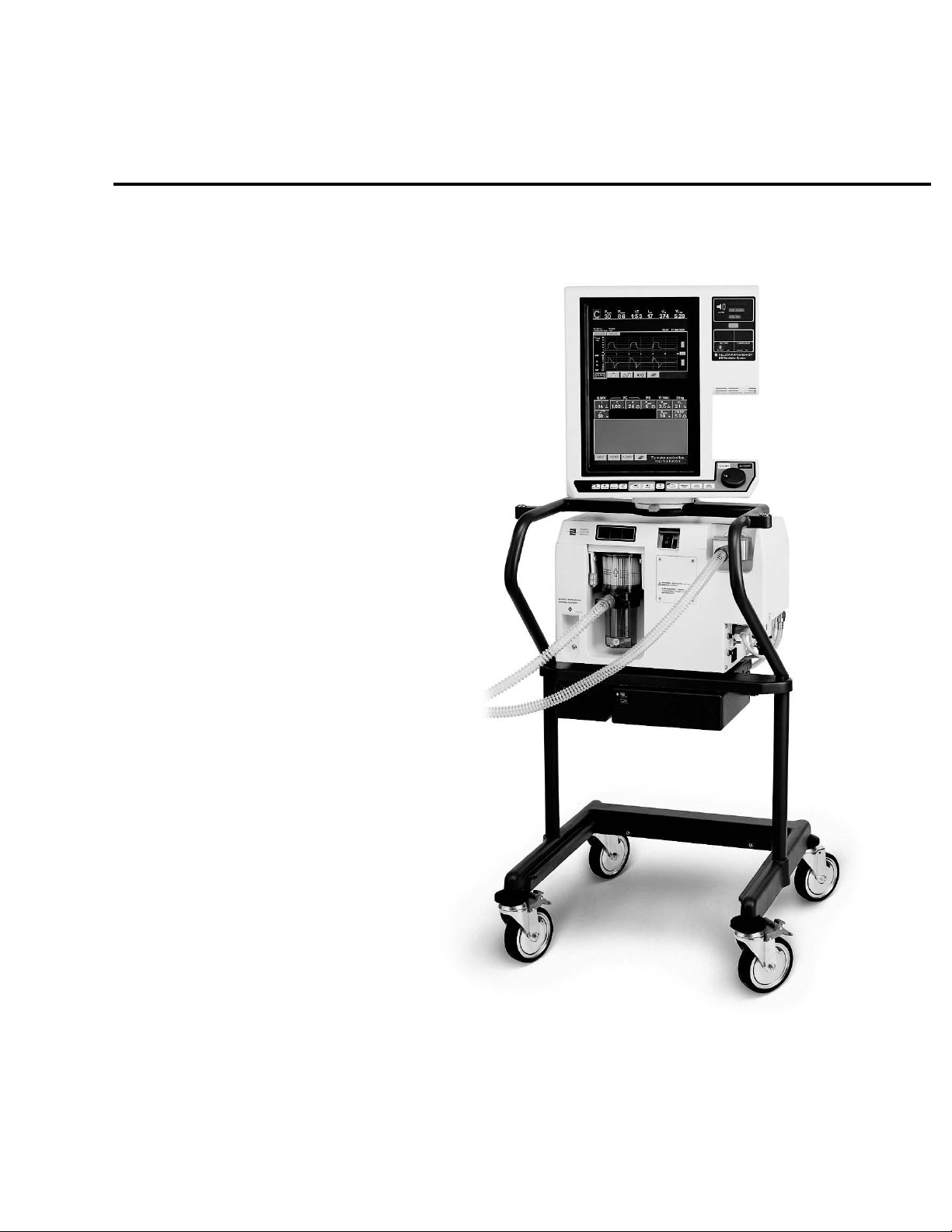
Figure 2-1. 840 Ventilator System . . . . . . . . . . . . . . . . . . . . . . . . . . . . . . . . . . . . . . . . . . . . . . . . . . . . 2-1
Figure 2-2. BDU . . . . . . . . . . . . . . . . . . . . . . . . . . . . . . . . . . . . . . . . . . . . . . . . . . . . . . . . . . . . . . . . . 2-2
Figure 2-3. 10.4-inch GUI . . . . . . . . . . . . . . . . . . . . . . . . . . . . . . . . . . . . . . . . . . . . . . . . . . . . . . . . . . 2-3
Figure 2-4. Compressor unit . . . . . . . . . . . . . . . . . . . . . . . . . . . . . . . . . . . . . . . . . . . . . . . . . . . . . . . . 2-3
Figure 2-5. BPS . . . . . . . . . . . . . . . . . . . . . . . . . . . . . . . . . . . . . . . . . . . . . . . . . . . . . . . . . . . . . . . . . . 2-4
Figure 2-6. Cart . . . . . . . . . . . . . . . . . . . . . . . . . . . . . . . . . . . . . . . . . . . . . . . . . . . . . . . . . . . . . . . . . 2-4
Figure 2-7. Patient system. . . . . . . . . . . . . . . . . . . . . . . . . . . . . . . . . . . . . . . . . . . . . . . . . . . . . . . . . . 2-5
Figure 2-8. NeoMode patient system . . . . . . . . . . . . . . . . . . . . . . . . . . . . . . . . . . . . . . . . . . . . . . . . . 2-5
Figure 2-9. 840 Ventilator System block diagram . . . . . . . . . . . . . . . . . . . . . . . . . . . . . . . . . . . . . . . . 2-6
Figure 2-10. Pneumatic system block diagram . . . . . . . . . . . . . . . . . . . . . . . . . . . . . . . . . . . . . . . . . . . 2-9
Figure 2-11. Pneumatic system diagram . . . . . . . . . . . . . . . . . . . . . . . . . . . . . . . . . . . . . . . . . . . . . . . 2-10
Figure 2-12. Inspiratory module . . . . . . . . . . . . . . . . . . . . . . . . . . . . . . . . . . . . . . . . . . . . . . . . . . . . . 2-14
Figure 2-13. Inspiratory module in ventilator . . . . . . . . . . . . . . . . . . . . . . . . . . . . . . . . . . . . . . . . . . . 2-14
Figure 2-14. Inspiratory module gas flow diagram . . . . . . . . . . . . . . . . . . . . . . . . . . . . . . . . . . . . . . . 2-15
Figure 2-15. Gas supply conditioning subsystem. . . . . . . . . . . . . . . . . . . . . . . . . . . . . . . . . . . . . . . . . 2-15
Figure 2-16. Gas supply conditioning subsystem gas flow diagram . . . . . . . . . . . . . . . . . . . . . . . . . . . 2-16
Figure 2-17. Gas supply conditioning subsystem components . . . . . . . . . . . . . . . . . . . . . . . . . . . . . . 2-18
Figure 2-18. Flow control subsystem. . . . . . . . . . . . . . . . . . . . . . . . . . . . . . . . . . . . . . . . . . . . . . . . . . 2-20
Figure 2-19. Flow control subsystem gas flow diagram . . . . . . . . . . . . . . . . . . . . . . . . . . . . . . . . . . . . 2-21
Figure 2-20. Hot film . . . . . . . . . . . . . . . . . . . . . . . . . . . . . . . . . . . . . . . . . . . . . . . . . . . . . . . . . . . . . 2-21
Figure 2-21. Flow control subsystem components. . . . . . . . . . . . . . . . . . . . . . . . . . . . . . . . . . . . . . . . 2-22
Figure 2-22. Safety valve and inspiration monitoring subsystem . . . . . . . . . . . . . . . . . . . . . . . . . . . . . 2-23
Figure 2-23. Inspiration monitoring subsystem gas flow diagram . . . . . . . . . . . . . . . . . . . . . . . . . . . . 2-24
Figure 2-24. Safety valve and inspiration monitoring subsystem components . . . . . . . . . . . . . . . . . . . 2-25
Figure 2-25. Safety valve open gas flow diagram . . . . . . . . . . . . . . . . . . . . . . . . . . . . . . . . . . . . . . . . 2-27
Figure 2-26. Air flow diagram . . . . . . . . . . . . . . . . . . . . . . . . . . . . . . . . . . . . . . . . . . . . . . . . . . . . . . . 2-28
Figure 2-27. Oxygen flow diagram . . . . . . . . . . . . . . . . . . . . . . . . . . . . . . . . . . . . . . . . . . . . . . . . . . . 2-30
Figure 2-28. Patient system (minus exhalation collector vial and expiratory filter) . . . . . . . . . . . . . . . . 2-31
Figure 2-29. Patient system flow diagram . . . . . . . . . . . . . . . . . . . . . . . . . . . . . . . . . . . . . . . . . . . . . . 2-32
Figure 2-30. Exhalation module (removed from BDU). . . . . . . . . . . . . . . . . . . . . . . . . . . . . . . . . . . . . 2-33
Figure 2-31. Exhalation module flow diagram. . . . . . . . . . . . . . . . . . . . . . . . . . . . . . . . . . . . . . . . . . . 2-34
840 Ventilatory System Service Manual 4-070496-00 Rev. A (08/03)
xvii
Page 18

Figures
Figure 2-32. Exhalation module components . . . . . . . . . . . . . . . . . . . . . . . . . . . . . . . . . . . . . . . . . . . 2-36
Figure 2-33. 806 compressor on cart. . . . . . . . . . . . . . . . . . . . . . . . . . . . . . . . . . . . . . . . . . . . . . . . . . 2-38
Figure 2-34. 806 Compressor Pneumatic diagram. . . . . . . . . . . . . . . . . . . . . . . . . . . . . . . . . . . . . . . . 2-38
Figure 2-35. 806 components . . . . . . . . . . . . . . . . . . . . . . . . . . . . . . . . . . . . . . . . . . . . . . . . . . . . . . . 2-39
Figure 2-36. Heat exchanger . . . . . . . . . . . . . . . . . . . . . . . . . . . . . . . . . . . . . . . . . . . . . . . . . . . . . . . . 2-40
Figure 2-37. 806 water trap assembly . . . . . . . . . . . . . . . . . . . . . . . . . . . . . . . . . . . . . . . . . . . . . . . . . 2-40
Figure 2-38. Air dryer assembly . . . . . . . . . . . . . . . . . . . . . . . . . . . . . . . . . . . . . . . . . . . . . . . . . . . . . . 2-40
Figure 2-39. 806 back panel . . . . . . . . . . . . . . . . . . . . . . . . . . . . . . . . . . . . . . . . . . . . . . . . . . . . . . . . 2-41
Figure 2-40. 806 cooling fans . . . . . . . . . . . . . . . . . . . . . . . . . . . . . . . . . . . . . . . . . . . . . . . . . . . . . . . 2-41
Figure 2-41. Electrical system block diagram . . . . . . . . . . . . . . . . . . . . . . . . . . . . . . . . . . . . . . . . . . . 2-49
Figure 2-42. ac panel. . . . . . . . . . . . . . . . . . . . . . . . . . . . . . . . . . . . . . . . . . . . . . . . . . . . . . . . . . . . . . 2-51
Figure 2-43. 840 Ventilator System interconnect diagram – ac panel . . . . . . . . . . . . . . . . . . . . . . . . . 2-52
Figure 2-44. Power switch (S1) and indicator . . . . . . . . . . . . . . . . . . . . . . . . . . . . . . . . . . . . . . . . . . . 2-53
Figure 2-45. Power supply assembly . . . . . . . . . . . . . . . . . . . . . . . . . . . . . . . . . . . . . . . . . . . . . . . . . . 2-54
Figure 2-46. 840 Ventilator System interconnect diagram – Power distribution . . . . . . . . . . . . . . . . . 2-55
Figure 2-47. BPS . . . . . . . . . . . . . . . . . . . . . . . . . . . . . . . . . . . . . . . . . . . . . . . . . . . . . . . . . . . . . . . . . 2-56
Figure 2-48. BPS battery pack . . . . . . . . . . . . . . . . . . . . . . . . . . . . . . . . . . . . . . . . . . . . . . . . . . . . . . . 2-57
Figure 2-49. BPS PCB. . . . . . . . . . . . . . . . . . . . . . . . . . . . . . . . . . . . . . . . . . . . . . . . . . . . . . . . . . . . . . 2-57
Figure 2-50. Card cage with all PCBs installed . . . . . . . . . . . . . . . . . . . . . . . . . . . . . . . . . . . . . . . . . . . 2-58
Figure 2-51. 840 Ventilator System interconnect diagram – Card cage . . . . . . . . . . . . . . . . . . . . . . . . 2-59
Figure 2-52. Motherboard PCB . . . . . . . . . . . . . . . . . . . . . . . . . . . . . . . . . . . . . . . . . . . . . . . . . . . . . . 2-60
Figure 2-53. Motherboard PCB in place. . . . . . . . . . . . . . . . . . . . . . . . . . . . . . . . . . . . . . . . . . . . . . . . 2-61
Figure 2-54. Motherboard PCB block diagram . . . . . . . . . . . . . . . . . . . . . . . . . . . . . . . . . . . . . . . . . . 2-62
Figure 2-55. BD CPU PCB . . . . . . . . . . . . . . . . . . . . . . . . . . . . . . . . . . . . . . . . . . . . . . . . . . . . . . . . . . 2-64
Figure 2-56. AI PCB . . . . . . . . . . . . . . . . . . . . . . . . . . . . . . . . . . . . . . . . . . . . . . . . . . . . . . . . . . . . . . . 2-67
Figure 2-57. Data key . . . . . . . . . . . . . . . . . . . . . . . . . . . . . . . . . . . . . . . . . . . . . . . . . . . . . . . . . . . . . 2-69
Figure 2-58. 10.4” GUI CPU PCB. . . . . . . . . . . . . . . . . . . . . . . . . . . . . . . . . . . . . . . . . . . . . . . . . . . . . 2-70
Figure 2-59. 9.4” GUI CPU PCB and backlight inverter PCB in place . . . . . . . . . . . . . . . . . . . . . . . . . . 2-70
Figure 2-60. 840 Ventilator System interconnect diagram – GUI 10.4-inch LCD panels . . . . . . . . . . . . 2-72
Figure 2-61. 840 Ventilator System interconnect diagram – GUI 9.4-inch LCD panels . . . . . . . . . . . . . 2-74
Figure 2-62. Touch Frame PCB . . . . . . . . . . . . . . . . . . . . . . . . . . . . . . . . . . . . . . . . . . . . . . . . . . . . . . 2-75
Figure 2-63. Keyboard assembly . . . . . . . . . . . . . . . . . . . . . . . . . . . . . . . . . . . . . . . . . . . . . . . . . . . . . 2-77
Figure 2-64. GUI LED PCB . . . . . . . . . . . . . . . . . . . . . . . . . . . . . . . . . . . . . . . . . . . . . . . . . . . . . . . . . . 2-78
Figure 2-65. 10.4” GUI LCD panels . . . . . . . . . . . . . . . . . . . . . . . . . . . . . . . . . . . . . . . . . . . . . . . . . . . 2-79
Figure 2-66. 9.4-inch LCD panels and backlight tubes. . . . . . . . . . . . . . . . . . . . . . . . . . . . . . . . . . . . . 2-80
Figure 2-67. GUI alarm assembly. . . . . . . . . . . . . . . . . . . . . . . . . . . . . . . . . . . . . . . . . . . . . . . . . . . . . 2-80
Figure 2-68. BDU LED PCB . . . . . . . . . . . . . . . . . . . . . . . . . . . . . . . . . . . . . . . . . . . . . . . . . . . . . . . . . 2-81
Figure 2-69. Inspiratory electronics PCB. . . . . . . . . . . . . . . . . . . . . . . . . . . . . . . . . . . . . . . . . . . . . . . . 2-81
Figure 2-70. 840 Ventilator System interconnect diagram – Inspiratory module . . . . . . . . . . . . . . . . . 2-82
Figure 2-71. Exhalation transducer PCB. . . . . . . . . . . . . . . . . . . . . . . . . . . . . . . . . . . . . . . . . . . . . . . . 2-83
Figure 2-72. 840 Ventilator System interconnect diagram – Exhalation module . . . . . . . . . . . . . . . . . 2-84
Figure 2-73. BD alarm assembly . . . . . . . . . . . . . . . . . . . . . . . . . . . . . . . . . . . . . . . . . . . . . . . . . . . . . 2-85
Figure 2-74. 806 compressor. . . . . . . . . . . . . . . . . . . . . . . . . . . . . . . . . . . . . . . . . . . . . . . . . . . . . . . . 2-85
Figure 2-75. 806 Compressor fans. . . . . . . . . . . . . . . . . . . . . . . . . . . . . . . . . . . . . . . . . . . . . . . . . . . . 2-86
Figure 2-76. 806 compressor PCBA installed . . . . . . . . . . . . . . . . . . . . . . . . . . . . . . . . . . . . . . . . . . . . 2-86
Figure 2-77. 806 compressor PCB block diagram . . . . . . . . . . . . . . . . . . . . . . . . . . . . . . . . . . . . . . . . 2-88
Figure 2-78. 840 Ventilator System interconnect diagram – Compressor unit . . . . . . . . . . . . . . . . . . . 2-89
Figure 2-79. Compressor operational sequence . . . . . . . . . . . . . . . . . . . . . . . . . . . . . . . . . . . . . . . . . . 2-91
Figure 2-80. Compressor unit start-up sequence . . . . . . . . . . . . . . . . . . . . . . . . . . . . . . . . . . . . . . . . . 2-92
xviii 4-070496-00 Rev. A (08/03) 840 Ventilatory System Service Manual
Page 19

Figures
Figure 2-81. Inspiration gas flow diagram . . . . . . . . . . . . . . . . . . . . . . . . . . . . . . . . . . . . . . . . . . . . . 2-93
Figure 2-82. Exhalation gas flow diagram . . . . . . . . . . . . . . . . . . . . . . . . . . . . . . . . . . . . . . . . . . . . . 2-96
Figure 2-83. Pressure transducer autozero mode gas flow diagram . . . . . . . . . . . . . . . . . . . . . . . . . . 2-99
Figure 2-84. Power loss sequence . . . . . . . . . . . . . . . . . . . . . . . . . . . . . . . . . . . . . . . . . . . . . . . . . . . 2-100
Figure 2-85. Safety valve open diagram . . . . . . . . . . . . . . . . . . . . . . . . . . . . . . . . . . . . . . . . . . . . . . 2-102
Figure 2-86. Pressure release, patient circuit occluded diagram. . . . . . . . . . . . . . . . . . . . . . . . . . . . . 2-104
Figure 3-1. Patient circuit setup for SST. . . . . . . . . . . . . . . . . . . . . . . . . . . . . . . . . . . . . . . . . . . . . . . 3-13
Figure 3-2. EST setup . . . . . . . . . . . . . . . . . . . . . . . . . . . . . . . . . . . . . . . . . . . . . . . . . . . . . . . . . . . . 3-19
Figure 3-3. EST screens during testing. . . . . . . . . . . . . . . . . . . . . . . . . . . . . . . . . . . . . . . . . . . . . . . . 3-20
Figure 4-1. SERVICE MODE screens . . . . . . . . . . . . . . . . . . . . . . . . . . . . . . . . . . . . . . . . . . . . . . . . . . 4-2
Figure 4-2. Service mode functions . . . . . . . . . . . . . . . . . . . . . . . . . . . . . . . . . . . . . . . . . . . . . . . . . . 4-4
Figure 4-3. System Information Log . . . . . . . . . . . . . . . . . . . . . . . . . . . . . . . . . . . . . . . . . . . . . . . . . . 4-6
Figure 4-4. EST/SST Diagnostic Log . . . . . . . . . . . . . . . . . . . . . . . . . . . . . . . . . . . . . . . . . . . . . . . . . . 4-6
Figure 6-1. Location of BD LED array. . . . . . . . . . . . . . . . . . . . . . . . . . . . . . . . . . . . . . . . . . . . . . . . . . 6-3
Figure 7-1. Alarm message format . . . . . . . . . . . . . . . . . . . . . . . . . . . . . . . . . . . . . . . . . . . . . . . . . . . 7-2
Figure 7-2. Alarm log . . . . . . . . . . . . . . . . . . . . . . . . . . . . . . . . . . . . . . . . . . . . . . . . . . . . . . . . . . . . . 7-3
Figure 8-1. GUI . . . . . . . . . . . . . . . . . . . . . . . . . . . . . . . . . . . . . . . . . . . . . . . . . . . . . . . . . . . . . . . . . . 8-7
Figure 8-2. 10.4-inch GUI front and back . . . . . . . . . . . . . . . . . . . . . . . . . . . . . . . . . . . . . . . . . . . . . . 8-8
Figure 8-3. 10.4-inch GUI mounting platform. . . . . . . . . . . . . . . . . . . . . . . . . . . . . . . . . . . . . . . . . . . 8-8
Figure 8-4. Removing and replacing 10.4-inch GUI cable assembly. . . . . . . . . . . . . . . . . . . . . . . . . . . 8-9
Figure 8-5. Removing 10.4-inch GUI rear housing. . . . . . . . . . . . . . . . . . . . . . . . . . . . . . . . . . . . . . . 8-10
Figure 8-6. 10.4-inch GUI rear warning label and serial number tag . . . . . . . . . . . . . . . . . . . . . . . . . 8-10
Figure 8-7. Removing the 10.4-inch CPU shield and GUI PCB . . . . . . . . . . . . . . . . . . . . . . . . . . . . . . 8-11
Figure 8-8. Removal of a 10.4-inch backlight inverter PCB . . . . . . . . . . . . . . . . . . . . . . . . . . . . . . . . 8-12
Figure 8-9. RS-232 shield and flex circuit . . . . . . . . . . . . . . . . . . . . . . . . . . . . . . . . . . . . . . . . . . . . . 8-12
Figure 8-10. GUI CPU PCB touch panel jumpers . . . . . . . . . . . . . . . . . . . . . . . . . . . . . . . . . . . . . . . . . 8-13
Figure 8-11. 10.4-inch LCD panels and LCD shield . . . . . . . . . . . . . . . . . . . . . . . . . . . . . . . . . . . . . . . 8-14
Figure 8-12. 10.4-inch GUI touchframe PCB and GUI LED PCB locations. . . . . . . . . . . . . . . . . . . . . . . 8-15
Figure 8-13. Removal of the 10.4" GUI LED PCB . . . . . . . . . . . . . . . . . . . . . . . . . . . . . . . . . . . . . . . . . 8-16
Figure 8-14. Removing the 10.4-inch GUI alarm . . . . . . . . . . . . . . . . . . . . . . . . . . . . . . . . . . . . . . . . . 8-17
Figure 8-15. 10.4-inch GUI rotor housing . . . . . . . . . . . . . . . . . . . . . . . . . . . . . . . . . . . . . . . . . . . . . . 8-19
Figure 8-16. 9.4-inch touch screen bezel and window . . . . . . . . . . . . . . . . . . . . . . . . . . . . . . . . . . . . 8-20
Figure 8-17. 9.4-inch GUI tilt positions . . . . . . . . . . . . . . . . . . . . . . . . . . . . . . . . . . . . . . . . . . . . . . . . 8-22
Figure 8-18. Replacing the 9.4-inch keyboard assembly . . . . . . . . . . . . . . . . . . . . . . . . . . . . . . . . . . . 8-23
Figure 8-19. 9.4-inch GUI mounting platform. . . . . . . . . . . . . . . . . . . . . . . . . . . . . . . . . . . . . . . . . . . 8-24
Figure 8-20. Removing 9.4-inch GUI handle assembly and interface cable . . . . . . . . . . . . . . . . . . . . . 8-25
Figure 8-21. Replacing 9.4-inch GUI rear housing . . . . . . . . . . . . . . . . . . . . . . . . . . . . . . . . . . . . . . . 8-26
Figure 8-22. 9.4" GUI interior . . . . . . . . . . . . . . . . . . . . . . . . . . . . . . . . . . . . . . . . . . . . . . . . . . . . . . . 8-27
Figure 8-23. Replacing the 9.4-inch GUI alarm assembly. . . . . . . . . . . . . . . . . . . . . . . . . . . . . . . . . . . 8-28
Figure 8-24. Replacing 9.4-inch backlight inverter and GUI LED PCBs. . . . . . . . . . . . . . . . . . . . . . . . . 8-29
Figure 8-25. Removing 9.4-inch GUI EMI shield . . . . . . . . . . . . . . . . . . . . . . . . . . . . . . . . . . . . . . . . . 8-30
Figure 8-26. Removing 9.4-inch video controller PCBs . . . . . . . . . . . . . . . . . . . . . . . . . . . . . . . . . . . . 8-31
Figure 8-27. GUI CPU PCB touch panel jumpers . . . . . . . . . . . . . . . . . . . . . . . . . . . . . . . . . . . . . . . . . 8-32
Figure 8-28. Replacing the 9.4-inch touchframe PCB and LCD panel assembly . . . . . . . . . . . . . . . . . 8-34
Figure 8-29. Routing the backlight extender cable assemblies. . . . . . . . . . . . . . . . . . . . . . . . . . . . . . . 8-35
840 Ventilatory System Service Manual 4-070496-00 Rev. A (08/03) xix
Page 20

Figures
Figure 8-30. LCD panel and backlight panel assembly. . . . . . . . . . . . . . . . . . . . . . . . . . . . . . . . . . . . . 8-37
Figure 8-31. Replacing the 9.4-inch GUI cooling vent filters . . . . . . . . . . . . . . . . . . . . . . . . . . . . . . . . 8-38
Figure 8-32. 9.4-inch rotor housing assembly . . . . . . . . . . . . . . . . . . . . . . . . . . . . . . . . . . . . . . . . . . . 8-39
Figure 8-33. BDU. . . . . . . . . . . . . . . . . . . . . . . . . . . . . . . . . . . . . . . . . . . . . . . . . . . . . . . . . . . . . . . . . 8-40
Figure 8-34. BDU connections. . . . . . . . . . . . . . . . . . . . . . . . . . . . . . . . . . . . . . . . . . . . . . . . . . . . . . . 8-43
Figure 8-35. Sure-Lock™ retainer and power cord. . . . . . . . . . . . . . . . . . . . . . . . . . . . . . . . . . . . . . . . 8-44
Figure 8-36. BDU release handle . . . . . . . . . . . . . . . . . . . . . . . . . . . . . . . . . . . . . . . . . . . . . . . . . . . . . 8-44
Figure 8-37. BD CPU PCB and AI PCB . . . . . . . . . . . . . . . . . . . . . . . . . . . . . . . . . . . . . . . . . . . . . . . . . 8-45
Figure 8-38. BD card cage and PCBs . . . . . . . . . . . . . . . . . . . . . . . . . . . . . . . . . . . . . . . . . . . . . . . . . 8-46
Figure 8-39. BDU I/O panel connections . . . . . . . . . . . . . . . . . . . . . . . . . . . . . . . . . . . . . . . . . . . . . . . 8-47
Figure 8-40. Replacing power supply assembly . . . . . . . . . . . . . . . . . . . . . . . . . . . . . . . . . . . . . . . . . . 8-48
Figure 8-41. Replacing power switch (S1) . . . . . . . . . . . . . . . . . . . . . . . . . . . . . . . . . . . . . . . . . . . . . . 8-49
Figure 8-42. Replacing humidifier receptacle . . . . . . . . . . . . . . . . . . . . . . . . . . . . . . . . . . . . . . . . . . . 8-50
Figure 8-43. ac panel . . . . . . . . . . . . . . . . . . . . . . . . . . . . . . . . . . . . . . . . . . . . . . . . . . . . . . . . . . . . . 8-51
Figure 8-44. Adding ferrites to air and oxygen transducer harnesses . . . . . . . . . . . . . . . . . . . . . . . . . . 8-53
Figure 8-45. Replacing F2 . . . . . . . . . . . . . . . . . . . . . . . . . . . . . . . . . . . . . . . . . . . . . . . . . . . . . . . . . . 8-54
Figure 8-46. Removing inspiratory module fascia panel . . . . . . . . . . . . . . . . . . . . . . . . . . . . . . . . . . . . 8-54
Figure 8-47. Oxygen filter assembly and pressure switches . . . . . . . . . . . . . . . . . . . . . . . . . . . . . . . . . 8-55
Figure 8-48. Pressure switches. . . . . . . . . . . . . . . . . . . . . . . . . . . . . . . . . . . . . . . . . . . . . . . . . . . . . . . 8-56
Figure 8-49. Replacing PSOL cartridge. . . . . . . . . . . . . . . . . . . . . . . . . . . . . . . . . . . . . . . . . . . . . . . . . 8-57
Figure 8-50. Removing inspiratory module . . . . . . . . . . . . . . . . . . . . . . . . . . . . . . . . . . . . . . . . . . . . . 8-58
Figure 8-51. Opening oxygen sensor access port. . . . . . . . . . . . . . . . . . . . . . . . . . . . . . . . . . . . . . . . . 8-59
Figure 8-52. Detail of oxygen sensor . . . . . . . . . . . . . . . . . . . . . . . . . . . . . . . . . . . . . . . . . . . . . . . . . . 8-60
Figure 8-53. Replacing oxygen sensor . . . . . . . . . . . . . . . . . . . . . . . . . . . . . . . . . . . . . . . . . . . . . . . . . 8-61
Figure 8-54. Inspiratory check valve (CV3) assembly . . . . . . . . . . . . . . . . . . . . . . . . . . . . . . . . . . . . . . 8-62
Figure 8-55. Removing inspiratory module right-side plate . . . . . . . . . . . . . . . . . . . . . . . . . . . . . . . . . 8-63
Figure 8-56. Replacing inspiratory module left-side plate . . . . . . . . . . . . . . . . . . . . . . . . . . . . . . . . . . 8-65
Figure 8-57. PSOL manifold ready for removal. . . . . . . . . . . . . . . . . . . . . . . . . . . . . . . . . . . . . . . . . . . 8-66
Figure 8-58. Replacing oxygen and air flow sensors (Q1 and Q2) and safety valve. . . . . . . . . . . . . . . . 8-67
Figure 8-59. Oxygen and air flow sensors (Q1 and Q2) . . . . . . . . . . . . . . . . . . . . . . . . . . . . . . . . . . . . 8-68
Figure 8-60. Safety valve . . . . . . . . . . . . . . . . . . . . . . . . . . . . . . . . . . . . . . . . . . . . . . . . . . . . . . . . . . . 8-69
Figure 8-61. Disassembling flow sensor manifold/regulator assembly/check valve assembly . . . . . . . . 8-71
Figure 8-62. Removing REG1 and REG2 . . . . . . . . . . . . . . . . . . . . . . . . . . . . . . . . . . . . . . . . . . . . . . . 8-72
Figure 8-63. Removing exhalation module cover . . . . . . . . . . . . . . . . . . . . . . . . . . . . . . . . . . . . . . . . 8-74
Figure 8-64. Exhalation module disassembled . . . . . . . . . . . . . . . . . . . . . . . . . . . . . . . . . . . . . . . . . . . 8-75
Figure 8-65. Replacing exhalation module. . . . . . . . . . . . . . . . . . . . . . . . . . . . . . . . . . . . . . . . . . . . . . 8-76
Figure 8-66. Exhalation sample port . . . . . . . . . . . . . . . . . . . . . . . . . . . . . . . . . . . . . . . . . . . . . . . . . . 8-77
Figure 8-67. Replacing exhalation module components . . . . . . . . . . . . . . . . . . . . . . . . . . . . . . . . . . . 8-78
Figure 8-68. Exhalation flow sensor (Q3) . . . . . . . . . . . . . . . . . . . . . . . . . . . . . . . . . . . . . . . . . . . . . . 8-81
Figure 8-69. Replacing exhalation transducer PCB. . . . . . . . . . . . . . . . . . . . . . . . . . . . . . . . . . . . . . . . 8-82
Figure 8-70. Replacing exhalation heater (EXH HTR) and check valve (CV5) . . . . . . . . . . . . . . . . . . . . 8-83
Figure 8-71. Removing BDU housing . . . . . . . . . . . . . . . . . . . . . . . . . . . . . . . . . . . . . . . . . . . . . . . . . 8-85
Figure 8-72. Removing motherboard PCB . . . . . . . . . . . . . . . . . . . . . . . . . . . . . . . . . . . . . . . . . . . . . 8-87
Figure 8-73. BDU alarm and motherboard PCB cable connections. . . . . . . . . . . . . . . . . . . . . . . . . . . . 8-88
Figure 8-74. Replacing power indicator . . . . . . . . . . . . . . . . . . . . . . . . . . . . . . . . . . . . . . . . . . . . . . . . 8-89
Figure 8-75. Cable connections to ac panel. . . . . . . . . . . . . . . . . . . . . . . . . . . . . . . . . . . . . . . . . . . . . 8-90
Figure 8-76. Replacing inspiratory blindmate cable . . . . . . . . . . . . . . . . . . . . . . . . . . . . . . . . . . . . . . . 8-91
Figure 8-77. Replacing dc power supply blindmate cable . . . . . . . . . . . . . . . . . . . . . . . . . . . . . . . . . . 8-92
Figure 8-78. Replacing ac power supply blindmate harness. . . . . . . . . . . . . . . . . . . . . . . . . . . . . . . . . 8-93
xx 4-070496-00 Rev. A (08/03) 840 Ventilatory System Service Manual
Page 21

Figures
Figure 8-79. 806 compressor mounted on cart . . . . . . . . . . . . . . . . . . . . . . . . . . . . . . . . . . . . . . . . . . 8-95
Figure 8-80. Top cover removed from compressor . . . . . . . . . . . . . . . . . . . . . . . . . . . . . . . . . . . . . . . 8-96
Figure 8-81. Fans installed in compressor . . . . . . . . . . . . . . . . . . . . . . . . . . . . . . . . . . . . . . . . . . . . . . 8-97
Figure 8-82. Removing the back panel of the compressor. . . . . . . . . . . . . . . . . . . . . . . . . . . . . . . . . . 8-98
Figure 8-83. Disconnecting filter outlet port from main supply hose . . . . . . . . . . . . . . . . . . . . . . . . . 8-100
Figure 8-84. Disconnecting heat exchanger inlet connection . . . . . . . . . . . . . . . . . . . . . . . . . . . . . . 8-100
Figure 8-85. 806 printed circuit board (PCB). . . . . . . . . . . . . . . . . . . . . . . . . . . . . . . . . . . . . . . . . . . 8-101
Figure 8-86. Air dryer/solenoid valve assemblies installed . . . . . . . . . . . . . . . . . . . . . . . . . . . . . . . . . 8-104
Figure 8-87. Air dryer and solenoid valve assemblies. . . . . . . . . . . . . . . . . . . . . . . . . . . . . . . . . . . . . 8-105
Figure 8-88. 806 compressor motor . . . . . . . . . . . . . . . . . . . . . . . . . . . . . . . . . . . . . . . . . . . . . . . . . 8-106
Figure 8-89. Water trap assembly . . . . . . . . . . . . . . . . . . . . . . . . . . . . . . . . . . . . . . . . . . . . . . . . . . . 8-106
Figure 8-90. BPS and cart . . . . . . . . . . . . . . . . . . . . . . . . . . . . . . . . . . . . . . . . . . . . . . . . . . . . . . . . . 8-110
Figure 8-91. Connecting BPS to BDU . . . . . . . . . . . . . . . . . . . . . . . . . . . . . . . . . . . . . . . . . . . . . . . . 8-111
Figure 8-92. Replacing battery pack and BPS PCB . . . . . . . . . . . . . . . . . . . . . . . . . . . . . . . . . . . . . . 8-112
Figure 8-93. Removing caster . . . . . . . . . . . . . . . . . . . . . . . . . . . . . . . . . . . . . . . . . . . . . . . . . . . . . . 8-113
Figure 8-94. Assembling GUI mount . . . . . . . . . . . . . . . . . . . . . . . . . . . . . . . . . . . . . . . . . . . . . . . . 8-114
Figure 8-95. Flex arm insert . . . . . . . . . . . . . . . . . . . . . . . . . . . . . . . . . . . . . . . . . . . . . . . . . . . . . . . 8-115
Figure 9-1. 840 Ventilator System patient system and accessories . . . . . . . . . . . . . . . . . . . . . . . . . . . .9-5
Figure 9-2. NeoMode patient circuit and accessories. . . . . . . . . . . . . . . . . . . . . . . . . . . . . . . . . . . . . . 9-7
Figure 9-3. Flex arm assembly . . . . . . . . . . . . . . . . . . . . . . . . . . . . . . . . . . . . . . . . . . . . . . . . . . . . . . 9-9
Figure 9-4. Oxygen hose assemblies . . . . . . . . . . . . . . . . . . . . . . . . . . . . . . . . . . . . . . . . . . . . . . . . 9-11
Figure 9-5. Air hose assemblies . . . . . . . . . . . . . . . . . . . . . . . . . . . . . . . . . . . . . . . . . . . . . . . . . . . . 9-13
Figure 9-6. Power cords . . . . . . . . . . . . . . . . . . . . . . . . . . . . . . . . . . . . . . . . . . . . . . . . . . . . . . . . . . 9-15
Figure 9-7. Ventilator major assemblies . . . . . . . . . . . . . . . . . . . . . . . . . . . . . . . . . . . . . . . . . . . . . . 9-17
Figure 9-8. Label kits (Sheet 1 of 2). . . . . . . . . . . . . . . . . . . . . . . . . . . . . . . . . . . . . . . . . . . . . . . . . . 9-23
Figure 9-9. 10.4-inch GUI assembly . . . . . . . . . . . . . . . . . . . . . . . . . . . . . . . . . . . . . . . . . . . . . . . . . 9-27
Figure 9-10. 10.4-inch GUI handle assembly. . . . . . . . . . . . . . . . . . . . . . . . . . . . . . . . . . . . . . . . . . . . 9-29
Figure 9-11. 10.4-inch GUI rotor assembly . . . . . . . . . . . . . . . . . . . . . . . . . . . . . . . . . . . . . . . . . . . . . 9-31
Figure 9-12. 10.4-inch GUI keyboard and speaker assembly . . . . . . . . . . . . . . . . . . . . . . . . . . . . . . . . 9-33
Figure 9-13. 9.4-inch GUI assembly . . . . . . . . . . . . . . . . . . . . . . . . . . . . . . . . . . . . . . . . . . . . . . . . . . 9-37
Figure 9-14. 9.4-inch GUI front housing assembly . . . . . . . . . . . . . . . . . . . . . . . . . . . . . . . . . . . . . . . 9-39
Figure 9-15. 9.4-inch GUI rear housing assembly . . . . . . . . . . . . . . . . . . . . . . . . . . . . . . . . . . . . . . . . 9-41
Figure 9-16. Breath delivery unit (BDU) . . . . . . . . . . . . . . . . . . . . . . . . . . . . . . . . . . . . . . . . . . . . . . . 9-45
Figure 9-17. Exhalation module . . . . . . . . . . . . . . . . . . . . . . . . . . . . . . . . . . . . . . . . . . . . . . . . . . . . . 9-47
Figure 9-18. Inspiratory module . . . . . . . . . . . . . . . . . . . . . . . . . . . . . . . . . . . . . . . . . . . . . . . . . . . . . 9-51
Figure 9-19. Proportional solenoid (PSOL) valve assembly . . . . . . . . . . . . . . . . . . . . . . . . . . . . . . . . . 9-53
Figure 9-20. Inspiratory module floor assembly . . . . . . . . . . . . . . . . . . . . . . . . . . . . . . . . . . . . . . . . . 9-57
Figure 9-21. BDU cover assembly . . . . . . . . . . . . . . . . . . . . . . . . . . . . . . . . . . . . . . . . . . . . . . . . . . . . 9-59
Figure 9-22. BDU chassis assembly . . . . . . . . . . . . . . . . . . . . . . . . . . . . . . . . . . . . . . . . . . . . . . . . . . . 9-61
Figure 9-23. BDU chassis kit . . . . . . . . . . . . . . . . . . . . . . . . . . . . . . . . . . . . . . . . . . . . . . . . . . . . . . . . 9-63
Figure 9-24. 806 compressor unit . . . . . . . . . . . . . . . . . . . . . . . . . . . . . . . . . . . . . . . . . . . . . . . . . . . 9-65
Figure 9-25. 806 compressor base assembly . . . . . . . . . . . . . . . . . . . . . . . . . . . . . . . . . . . . . . . . . . . 9-67
Figure 9-26. Compressor unit enclosure assembly . . . . . . . . . . . . . . . . . . . . . . . . . . . . . . . . . . . . . . . 9-69
Figure 9-27. Compressor plenum assembly . . . . . . . . . . . . . . . . . . . . . . . . . . . . . . . . . . . . . . . . . . . . 9-71
Figure 9-28. Backup power source (BPS) . . . . . . . . . . . . . . . . . . . . . . . . . . . . . . . . . . . . . . . . . . . . . . 9-73
Figure 9-29. Cart assembly . . . . . . . . . . . . . . . . . . . . . . . . . . . . . . . . . . . . . . . . . . . . . . . . . . . . . . . . 9-75
840 Ventilatory System Service Manual 4-070496-00 Rev. A (08/03) xxi
Page 22

Figures
This page intentionally blank.
xxii 4-070496-00 Rev. A (08/03) 840 Ventilatory System Service Manual
Page 23

SECTION
TABLES
Table 1-1. Ventilator specifications. . . . . . . . . . . . . . . . . . . . . . . . . . . . . . . . . . . . . . . . . . . . . . . . . . . . . 1-3
Table 1-2. Compliance with standards . . . . . . . . . . . . . . . . . . . . . . . . . . . . . . . . . . . . . . . . . . . . . . . . . . 1-7
Table 1-3. Technical information . . . . . . . . . . . . . . . . . . . . . . . . . . . . . . . . . . . . . . . . . . . . . . . . . . . . . . 1-8
Table 1-4. Ventilator range, resolution, accuracy, new patient/defaults . . . . . . . . . . . . . . . . . . . . . . . . 1-10
Table 1-5. Tools, equipment, and service materials . . . . . . . . . . . . . . . . . . . . . . . . . . . . . . . . . . . . . . . 1-19
Table 1-6. Schedule of periodic maintenance . . . . . . . . . . . . . . . . . . . . . . . . . . . . . . . . . . . . . . . . . . . 1-23
Table 1-7. Service kits . . . . . . . . . . . . . . . . . . . . . . . . . . . . . . . . . . . . . . . . . . . . . . . . . . . . . . . . . . . . . 1-24
Table 1-8. GUI front view. . . . . . . . . . . . . . . . . . . . . . . . . . . . . . . . . . . . . . . . . . . . . . . . . . . . . . . . . . . 1-25
Table 1-9. GUI rear view . . . . . . . . . . . . . . . . . . . . . . . . . . . . . . . . . . . . . . . . . . . . . . . . . . . . . . . . . . . 1-31
Table 1-10. BDU front view . . . . . . . . . . . . . . . . . . . . . . . . . . . . . . . . . . . . . . . . . . . . . . . . . . . . . . . . . . 1-32
Table 1-11. BDU I/O panel. . . . . . . . . . . . . . . . . . . . . . . . . . . . . . . . . . . . . . . . . . . . . . . . . . . . . . . . . . . 1-35
Table 1-12. BDU right-side panel . . . . . . . . . . . . . . . . . . . . . . . . . . . . . . . . . . . . . . . . . . . . . . . . . . . . . . 1-37
Table 1-13. BDU rear view . . . . . . . . . . . . . . . . . . . . . . . . . . . . . . . . . . . . . . . . . . . . . . . . . . . . . . . . . . . 1-38
Table 1-14. GUI rear view . . . . . . . . . . . . . . . . . . . . . . . . . . . . . . . . . . . . . . . . . . . . . . . . . . . . . . . . . . . 1-39
Table 1-15. BPS controls and indicators . . . . . . . . . . . . . . . . . . . . . . . . . . . . . . . . . . . . . . . . . . . . . . . . . 1-40
Table 2-1. Pneumatic component descriptions . . . . . . . . . . . . . . . . . . . . . . . . . . . . . . . . . . . . . . . . . . 2-11
Table 2-2. Electronic Component Descriptions. . . . . . . . . . . . . . . . . . . . . . . . . . . . . . . . . . . . . . . . . . . 2-43
Table 2-3. NOVRAM contents . . . . . . . . . . . . . . . . . . . . . . . . . . . . . . . . . . . . . . . . . . . . . . . . . . . . . . . 2-66
Table 2-4. Monitored data . . . . . . . . . . . . . . . . . . . . . . . . . . . . . . . . . . . . . . . . . . . . . . . . . . . . . . . . . . 2-97
Table 2-5. Out-of-tolerance supply voltages. . . . . . . . . . . . . . . . . . . . . . . . . . . . . . . . . . . . . . . . . . . . 2-101
Table 3-1. Self tests . . . . . . . . . . . . . . . . . . . . . . . . . . . . . . . . . . . . . . . . . . . . . . . . . . . . . . . . . . . . . . . . 3-2
Table 3-2. Components tested by self tests . . . . . . . . . . . . . . . . . . . . . . . . . . . . . . . . . . . . . . . . . . . . . . 3-3
Table 3-4. POST outcomes. . . . . . . . . . . . . . . . . . . . . . . . . . . . . . . . . . . . . . . . . . . . . . . . . . . . . . . . . . . 3-9
Table 3-3. POST Structure . . . . . . . . . . . . . . . . . . . . . . . . . . . . . . . . . . . . . . . . . . . . . . . . . . . . . . . . . . 3-10
Table 3-5. Hardware requirements for SST . . . . . . . . . . . . . . . . . . . . . . . . . . . . . . . . . . . . . . . . . . . . . . 3-12
Table 3-6. SST tests . . . . . . . . . . . . . . . . . . . . . . . . . . . . . . . . . . . . . . . . . . . . . . . . . . . . . . . . . . . . . . . 3-15
Table 3-7. SST individual test results. . . . . . . . . . . . . . . . . . . . . . . . . . . . . . . . . . . . . . . . . . . . . . . . . . . 3-16
Table 3-8. Overall SST outcomes . . . . . . . . . . . . . . . . . . . . . . . . . . . . . . . . . . . . . . . . . . . . . . . . . . . . . 3-16
Table 3-9. Hardware requirements for EST . . . . . . . . . . . . . . . . . . . . . . . . . . . . . . . . . . . . . . . . . . . . . . 3-18
Table 3-10. EST tests . . . . . . . . . . . . . . . . . . . . . . . . . . . . . . . . . . . . . . . . . . . . . . . . . . . . . . . . . . . . . . . 3-21
Table 3-11. EST individual test results. . . . . . . . . . . . . . . . . . . . . . . . . . . . . . . . . . . . . . . . . . . . . . . . . . . 3-23
Table 3-12. Overall EST outcomes . . . . . . . . . . . . . . . . . . . . . . . . . . . . . . . . . . . . . . . . . . . . . . . . . . . . . 3-23
Table 4-1. Service mode functions . . . . . . . . . . . . . . . . . . . . . . . . . . . . . . . . . . . . . . . . . . . . . . . . . . . . . 4-3
Table 4-2. Other screens . . . . . . . . . . . . . . . . . . . . . . . . . . . . . . . . . . . . . . . . . . . . . . . . . . . . . . . . . . . . 4-8
Table 4-3. Service Mode Setup. . . . . . . . . . . . . . . . . . . . . . . . . . . . . . . . . . . . . . . . . . . . . . . . . . . . . . . . 4-8
Table 4-4. Exhalation valve calibration errors . . . . . . . . . . . . . . . . . . . . . . . . . . . . . . . . . . . . . . . . . . . . . 4-9
Table 4-5. Vent Inop Test phases . . . . . . . . . . . . . . . . . . . . . . . . . . . . . . . . . . . . . . . . . . . . . . . . . . . . . 4-11
Table 4-6. Vent Inop Test troubleshooting . . . . . . . . . . . . . . . . . . . . . . . . . . . . . . . . . . . . . . . . . . . . . . 4-12
Table 4-7. Flow sensor calibration errors . . . . . . . . . . . . . . . . . . . . . . . . . . . . . . . . . . . . . . . . . . . . . . . 4-13
Table 4-8. Initialize Flow Sensor errors . . . . . . . . . . . . . . . . . . . . . . . . . . . . . . . . . . . . . . . . . . . . . . . . . 4-14
840 Ventilatory System Service Manual 4-070496-00 Rev. A (08/03)
xxiii
Page 24

Tables
Table 4-9. Cal Info Duplication errors . . . . . . . . . . . . . . . . . . . . . . . . . . . . . . . . . . . . . . . . . . . . . . . . . . 4-14
Table 4-10. Serial number setup errors . . . . . . . . . . . . . . . . . . . . . . . . . . . . . . . . . . . . . . . . . . . . . . . . . . 4-16
Table 4-11. Datakey update error . . . . . . . . . . . . . . . . . . . . . . . . . . . . . . . . . . . . . . . . . . . . . . . . . . . . . . 4-17
Table 4-12. Serial Loopback Test error . . . . . . . . . . . . . . . . . . . . . . . . . . . . . . . . . . . . . . . . . . . . . . . . . . 4-17
Table 5-1. Tools, equipment, and service materials required for
performance verification 5-2
Table 5-2. Pre-performance verification testing and calibration requirements . . . . . . . . . . . . . . . . . . . . . 5-6
Table 5-3. Manual ventilator check target values . . . . . . . . . . . . . . . . . . . . . . . . . . . . . . . . . . . . . . . . . 5-11
Table 6-1. Values of diagnostic code digits . . . . . . . . . . . . . . . . . . . . . . . . . . . . . . . . . . . . . . . . . . . . . . . 6-4
Table 6-2. 840 Ventilator diagnostic codes . . . . . . . . . . . . . . . . . . . . . . . . . . . . . . . . . . . . . . . . . . . . . . . 6-7
Table 6-3. Address codes for BDU POST analog devices test errors . . . . . . . . . . . . . . . . . . . . . . . . . . . . 6-54
Table 6-4. BDU and GUI—Phase 1 (kernal) POST diagnostic codes . . . . . . . . . . . . . . . . . . . . . . . . . . . . 6-56
Table 6-5. BDU only—Phase 2 POST diagnostic codes . . . . . . . . . . . . . . . . . . . . . . . . . . . . . . . . . . . . . 6-58
Table 6-7. BDU or GUI—Phase 3 POST diagnostic codes . . . . . . . . . . . . . . . . . . . . . . . . . . . . . . . . . . . 6-63
Table 6-8. Interrupt errors and test failures – POST self tests . . . . . . . . . . . . . . . . . . . . . . . . . . . . . . . . . 6-64
Table 6-9. SST diagnostic codes . . . . . . . . . . . . . . . . . . . . . . . . . . . . . . . . . . . . . . . . . . . . . . . . . . . . . . 6-66
Table 6-11. UT0002 Fault Addresses for LCD inverter PCB errors . . . . . . . . . . . . . . . . . . . . . . . . . . . . . 6-102
Table 7-1. How the ventilator responds to alarm conditions . . . . . . . . . . . . . . . . . . . . . . . . . . . . . . . . . . 7-1
Table 7-2. Alarm messages . . . . . . . . . . . . . . . . . . . . . . . . . . . . . . . . . . . . . . . . . . . . . . . . . . . . . . . . . . . 7-3
Table 8-1. Testing and calibration requirements . . . . . . . . . . . . . . . . . . . . . . . . . . . . . . . . . . . . . . . . . . . 8-5
Table 8-2. Differences between 9.4-inch and 10.4-inch GUI . . . . . . . . . . . . . . . . . . . . . . . . . . . . . . . . . . 8-6
Table 8-3. GUI part replacement chart . . . . . . . . . . . . . . . . . . . . . . . . . . . . . . . . . . . . . . . . . . . . . . . . . . 8-7
Table 8-4. BDU part replacement chart. . . . . . . . . . . . . . . . . . . . . . . . . . . . . . . . . . . . . . . . . . . . . . . . . 8-41
Table 9-1. Abbreviations used in parts list. . . . . . . . . . . . . . . . . . . . . . . . . . . . . . . . . . . . . . . . . . . . . . . . 9-2
xxiv 4-070496-00 Rev. A (08/03) 840 Ventilatory System Service Manual
Page 25

SECTION
SECTION
General information 1
This section provides introductory information on the Puritan Bennett 840 Ventilator
System. Included are a description of the ventilator, including specifications, required tools
and test equipment, schedule of maintenance, and controls and indicators.
1.1 How to use this manual
This manual describes how to service the 840 Ventilator System. Puritan Bennett
recommends that you become familiar with this manual and accompanying labels before
attempting to operate or maintain the ventilator.
The 840 Ventilator System Service Manual is intended to be used in conjunction with the 840
Ventilator System Operator’s and Technical Reference Manual. Both manuals are needed for field
repair of the ventilator.
In several cases, however, similar information is contained in both manuals:
• Refer to the “Maintenance and service” section of the 840 Ventilator System Operator’s and
Technical Reference Manual for operator maintenance of filters and the patient system.
Refer to Section 8 of this manual for complete ventilator maintenance information.
1
• Refer to the “Part numbers” appendix of the 840 Ventilator System Operator’s and Technical
Reference Manual for patient system part numbers. Refer to Section 9 of this manual for
complete part ordering information.
1.2 General product description
The Puritan Bennett 840 Ventilator System is a critical care ventilator intended for acute and
subacute care of infant, pediatric, and adult patients.
Electronically controlled and pneumatically powered, the 840 Ventilator System contains a
breath delivery unit (BDU), graphical user interface (GUI), and backup power source (BPS). An
optional compressor unit and cart are also available.
The BDU is the core of the ventilator. It contains the pneumatics that deliver gas and
electronic and electrical systems that control pneumatics, monitor alarms, and distribute
power. The ventilator includes two independent central processing units (CPUs): one for the
BDU that controls ventilation, and one for the GUI that monitors ventilator and patient data.
The GUI CPU verifies that the BD CPU is functioning properly and prevents a single fault
from causing a simultaneous failure of controlling and monitoring operations.
The GUI provides a communications path between the ventilator and the operator. By using
the touch screen, keys, and knob on the GUI the practitioner gives initial instructions and
data to the ventilator. The GUI CPU processes this information and stores it in the ventilator’s
memory. The BD CPU uses this stored information to control and monitor the flow of gas to
and from the patient.
The 840 Ventilator System supplies mandatory or spontaneous breaths with a preset oxygen
concentration. A mandatory breath can be pressure- or volume-controlled. A spontaneous
breath allows the patient peak inspiratory flows up to 200 L/min with or without pressure
support.
840 Ventilator System Service Manual 4-070496-00 Rev. A (08/03)
1-1
Page 26

1 General information
The BPS (Backup Power Supply) provides dc power to the BDU in the event that ac power is
lost. A new, fully charged BPS allows the ventilator to function (without compressor or
humidifier) for at least 30 minutes; thus, the BPS can power the ventilator for transport
purposes within the respiratory care facility. The BPS should always be connected to the
ventilator during operation.
The optional compressor unit provides compressed air to the BDU, and can be used in place
of wall or bottled air for normal operation. The compressor unit is powered by and
communicates with the BDU.
NOTE:
An external air source is required when performing service mode calibrations and
performance verification testing.
1.3 Configuration information
The 840 Ventilator System is available in a variety of versions, intended to meet differing
needs and regulations throughout the world. The major differences in configuration among
ventilators are listed below:
Electrical requirements: Available in 100 V, 50/60 Hz; 120 V, 60 Hz; 220
220
Languages: Keyboard, labels, software, and operator’s manual available in a variety of
languages.
Compressor: With or without compressor unit.
Mounting: Cart- or shelf-mount available.
Power cord: A variety of plug ends are available. Refer to the parts list in Section 9 of this
manual or the 840 Ventilator System Operator’s and Technical Reference Manual for specific part
numbers.
Oxygen and air fittings: Ventilator available with diameter index safety standard (DISS)
male, DISS female, noninterchangeable screw thread (NIST) male, Air Liquide, and sleeve
index system (SIS) male fittings.
Oxygen and air hoses: Versions available to connect to DISS male, Air Liquide, SIS male,
British Oxygen Company (BOC) female, NIST male, and Dräger female supply fittings. DISS
female x DISS female versions available in different colors to satisfy different countries’
requirements.
Accessories: Ventilators may be equipped with accessories listed in Section 1.4.
1.4 Accessories
The following accessories are either required or can be used with the ventilator.
Patient circuit: A variety of reusable Puritan Bennett patient circuits, adult and pediatric,
with and without water traps, and with and without heated wire, is available. Consult the
“Part numbers” appendix of the 840 Ventilator System Operator’s and Technical Reference Manual
for patient circuit ordering information.
– 240 V, 50 Hz;
– 240 V, 60 Hz.
Humidification device: The 840 Ventilator System supports the use of an optional
humidification device, including a heated humidifier, heat and moisture exchanger (HME),
or heated wire. A mounting bracket is available for the Fisher & Paykel M480/M730
Humidifier. An ac socket for the humidifier is available on 100 and 120 V ventilators.
Remote nurse call unit: An analog output connector permits connection to a remote nurse
call unit. (Puritan Bennett does not supply nurse’s call units or cables.) Refer to the 840
Ventilator System Operator’s and Technical Reference Manual for nurse call specificati ons.
1-2 4-070496-00 Rev. A (08/03) 840 Ventilator System Service Manual
Page 27

General information 1
1.5 Specifications
Table 1-1: Ventilator specifications
Physical characteristics
Weight Breath delivery unit (BDU): 18.2 kg (40.1 lb)
Graphic user interface (GUI): 5.7 kg (12.6 lb)
Backup power source (BPS): 6.6 kg (14.6 lb)
Cart: 15.5 kg (34.2 lb)
804 Compressor unit: 31.6 kg (69.7 lb)
806 Compressor unit (100 V, 120 V): 23.6 kg (52 lb)
806 Compressor unit (220 V): 24.5 kg (54 lb)
Dimensions BDU: 330 mm high x 457 mm wide x 254 mm deep (13 in. high x 18 in. wide x 10 in. deep)
GUI: 460 mm high x 394 mm wide x 170 mm deep (18.1 in. high x 15.5 in. wide x 6.7 in. deep)
BPS: 83 mm high x 244 mm wide x 254 mm deep (3.25 in. high x 9.6 in. wide x 10 in. deep)
Cart: 998 mm high x 582 mm wide x 602 mm deep (39.3 in. high x 22.9 in. wide x 23.7 in. deep)
804 Compressor: 417 mm high x 458 mm wide x 362 mm deep (16.4 in. high x 18 in. wide x 14.25
in. deep)
806 Compressor: 425 mm high x 458 mm wide x 362 mm deep (17 in. high x 18 in. wide x 14.25
in. deep)
Connectors Inspiratory limb connector: ISO 22-mm conical male
Expiratory limb connector (on expiratory filter): ISO 22-mm conical male
Air and oxygen inlets: DISS male, DISS female, NIST, Air Liquide, or SIS fitting (depending on country
and configuration)
Environmental requirements
Temperature Operating: 10 to 40 °C (50 to 104 °F) at 10 to 95% relative humidity, noncondensing
Storage: -20 to 50 °C (-4 to 122 °F) at 10 to 95% relative humidity, noncondensing
Atmospheric
pressure
Altitude Operating: -443 to 3280 m (-1350 to 10,000 ft)
Pneumatic specifications
Oxygen and air inlet
supplies
Operating: 700 to 1060 hPa (10.2 to 15.4 psi)
Storage: 500 to 1060 hPa (7.3 to 15.4 psi)
Storage: Up to 6560 m (20,000 ft)
Pressure: 241 to 690 kPa (35 to 100 psi)
Warning
Due to excessive restriction of the Air Liquide, SIS, and Dräger hose assemblies, reduced
ventilator performance levels may result when oxygen or air supply pressures < 50 psi
(345 kPa) are employed.
Flow: Maximum of 200 L/min
Oxygen sensor life The oxygen sensor should be replaced two years after date of manufacture, or as often as necessary.
Actual sensor life depends on operating environment; operation at higher temperature or O
will shorten sensor life.
840 Ventilator System Service Manual 4-070496-00 Rev. A (08/03) 1-3
% levels
2
Page 28
1 General information
Table 1-1: Ventilator specifications (continued)
Gas mixing system Range of flow from the mixing system: Can be set to 150 L/min standard temperature and pressure,
dry (STPD). Additional flow is available (up to 80 L/min for pediatric patients whose IBW ≤ 24 kg,
and up to 200 L/min for adults whose IBW > 24 kg) for compliance compensation.
Leakage from one gas system to another: Meets standard EN 60601-2-12.
Operating pressure range: 35 to 100 psi (241 to 690 kPa)
Air/oxygen regulator bleed: Up to 3 L/min
Electrical specifications
Input power Ventilator operation without compressor:
100 V~, 50/60 Hz; 5.1 A; 510 VA
120 V~, 60 Hz; 4.5 A; 540 VA
220 – 240 V~, 50 Hz; 1.5 A; 330 - 360 VA
220 – 240 V~, 60 Hz; 1.5 A; 330 - 360 VA
Ventilator operation with compressor:
100 V~, 50/60 Hz; 10.7 A; 1070 VA
120 V~, 60 Hz; 10.1 A; 1212 VA
220 – 240 V~, 50 Hz; 4.1 A; 902 - 984 VA
220 – 230 V~, 60 Hz; 4.1 A; 902 - 943 VA
Mains overcurrent release:
Ventilator: 5 A, 100 – 120 V~; 5 A, 220 – 240 V~
Auxiliary mains: 10 A, 100 – 120 V~; 5 A, 220 – 240 V~
Ventilator operation without humidifier or compressor:
Approximately 1126 BTU
Ventilator operation with 806 compressor and without humidifier:
Approximately 3078 BTU
NOTE:
Above values obtained using the following ventilator settings at 22 °C ambient temperature: mode, A/C; mandatory
type, PC; IBW, 85 kg; f
50%; P
humidifiers. (Humidifier connection only available on 100 – 120 V ventilators.)
Leakage current Earth leakage current:
, 50 cmH2O; P
MEAN
, 20/min; P
TOT
Enclosure/patient leakage current:
Humidifier leakage current: 50 µA maximum
Patient auxiliary leakage current: Not applicable
, 3 cmH2O. Input power specifications are for ventilators with Fisher & Paykel MR730
SENS
At 100 – 120 V~ operation: 300 µA
At 220 – 240 V~ operation: 500 µA
100 – 120 V~ operation: 100 µA maximum
220 – 240 V~ operation: 100 µA maximum
, 30 cmH2O; TI, 1 s; Rise Time Percent (was Flow Acceleration), 50%; O2%,
SUPP
Warning
In the event of a defective earth conductor, connecting equipment to the auxiliary mains
socket outlet(s) (that is, the humidifier or compressor connections) may increase patient
leakage current to values that exceed the allowable limits.
Alarm volume 45 dB(A) to 85 dB(A)
1-4 4-070496-00 Rev. A (08/03) 840 Ventilator System Service Manual
Page 29
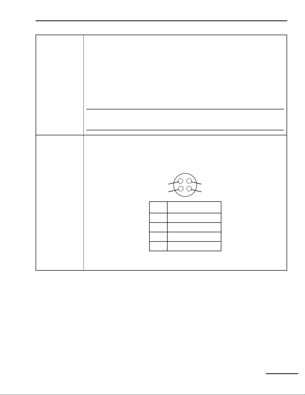
General information 1
Table 1-1: Ventilator specifications (continued)
802 Backup Power
Source (BPS)
Communications
capabilities
24 V dc, 6.5 Ah
Operating time (for a new, fully charged battery): at least 30 minutes. Actual duration depends on
ventilator settings, battery age, and level of battery charge.
Recharge time: Automatically recharges within 8 hours maximum while ventilator is connected to ac
power.
Shelf life: 24 months from date of manufacture.
Recharge requirements: Recharge every 6 months when storage temperature is -20 to 29 °C (-5 to
84 °F); every 3 months when storage temperature is 30 to 40 °C (86 to 104 °F); every 2 months
when storage temperature is 41 to 50 °C (105 to 122 °F).
Storage conditions: Store at -20 to 50 °C (-4 to 122 °F), 25 to 85% relative humidity; avoid direct
sunlight.
NOTE:
BPS battery life specifications are approximate. To ensure maximum battery life, maintain full
charge and minimize the number of complete discharges.
Remote alarm (nurse’s call) port (Figure 1-1). Allows medium- and high-urgency alarm conditions
to be annunciated at locations away from the ventilator (for example, when the ventilator is in an
isolation room). The ventilator signals an alarm using a normally open or a normally closed signal.
The ventilator asserts a remote alarm when there is an active medium- or high-urgency alarm
condition, unless the alarm silence function is active. The remote alarm port is a 4-pin female
connector. Allowable current is 500 mA at 30 V dc (maximum).
4
3
1
2
8-00020
Pin Signal
1 Normally closed (NC)
2Relay common
3 Normally open (NO)
4 Not connected
Figure 1-1. Remote alarm (nurse’s call) port pinout
840 Ventilator System Service Manual 4-070496-00 Rev. A (08/03) 1-5
Page 30
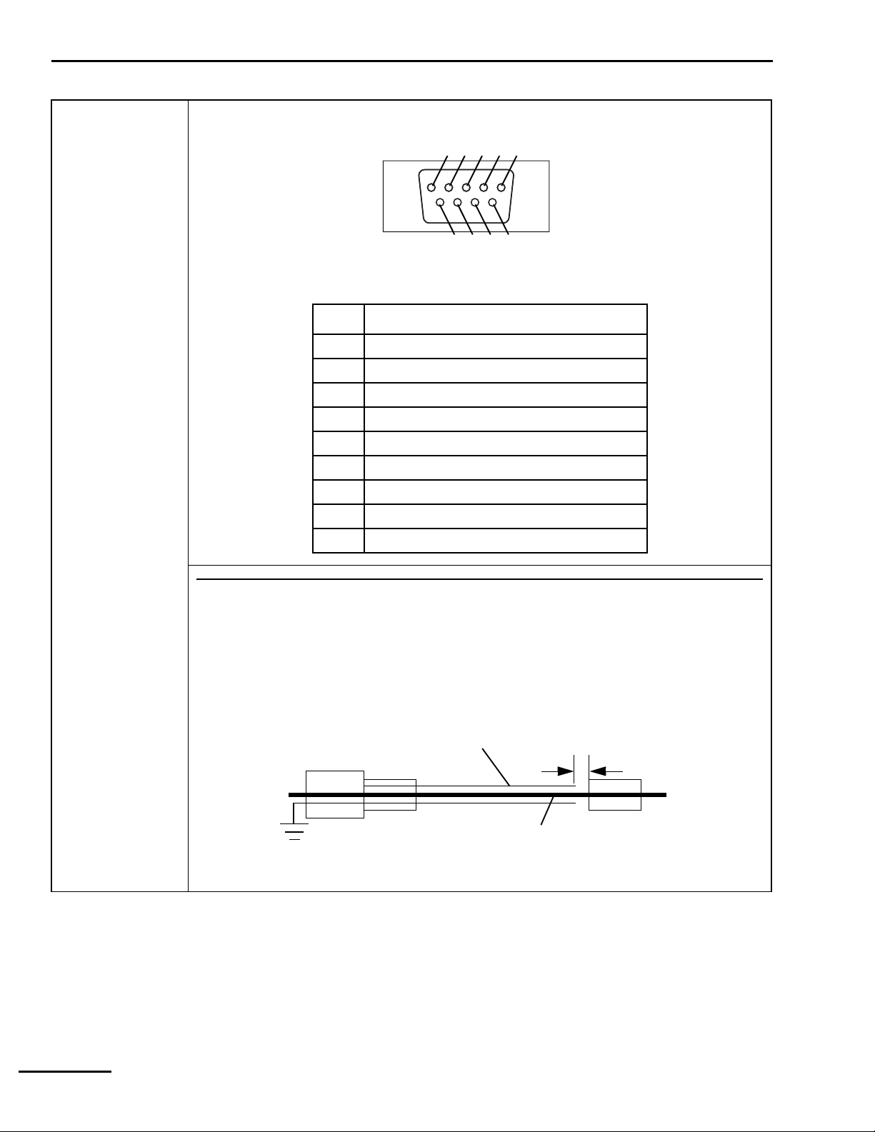
1 General information
Table 1-1: Ventilator specifications (continued)
Communication
capabilities (cont)
RS-232 (serial) port (Figure 1-2). A 9-pin male connector configured as data terminal equipment
(DTE). Allowable current is 0.2 A at 10 V dc (maximum).
1 2 3 4 5
8
6
9
7
8-00019
Figure 1-2. 840 Ventilator System RS-232 serial port pinout
Pin Signal
1 Not connected
2 Receive data (RxD)
3 Transmit data (TxD
4 Data terminal ready (DTR), terminated high
5Ground (GND)
6 Not connected
7 Request to send (RTS)
8 Clear to send (CTS)
9 Not connected
NOTE:
The connection of accessories or equipment to the ventilator’s RS-232 and remote alarm ports
requires electrical separation of conductive earth (ground) connections between different items of
equipment of a system. The system cable assembly shielding can interconnect the ventilator and
other equipment, increasing the risk of excessive enclosure leakage current from external
equipment. For safe connection and prevent a double earth ground, the shield conductor must have
separation of 4 mm between the equipment and ventilator conductors, as shown below:
Minimum shield
separation
4 mm
To accessory equipment
connector
To
840
Ventilator RS-232 and
remote alarm input connectors
Cable shield earth to ventilator
enclosure protective earth
Cable conductive
shielding
Cable signal lines
1-6 4-070496-00 Rev. A (08/03) 840 Ventilator System Service Manual
Page 31

General information 1
1.6 Compliance and approvals
The 840 Ventilator System was developed in accordance with pertinent FDA guidances and
North American and EN 46001/ISO 13485 international standards (Table 1-2). The
manufacturing facility for this product is EN 46001 certified.
The ventilator’s IEC 60601-1/EN 60601-1 classification is Protection class I, Type B, internally
powered, IPX1 drip-proof equipment, continuous operation.
Table 1-2: Compliance with standards
Standards/certifications Configurations Certification agency
North America
Authorized to bear the CSA certification mark,
signifying the product has been evaluated to
the applicable ANSI/Underwriters
Laboratories Inc. (UL) and CSA standards for
use in the US and Canada.
CSA C22.2 No. 601.1
CSA C22.2 No. 601.1 Supplement 1
IEC No. 60601-2-12
UL No. 2601-1
Worldwide
CB scheme certification:
IEC 60601-1
IEC 60601-1-1
IEC 60601-1-2
IEC 60601-2-12
IEC 60601-1-4
ISO 10651-1
European
120 V, 60 Hz
220 – 240 V, 50 Hz
220 – 240 V, 60 Hz
100 V, 50/60 Hz
120 V, 60 Hz
220 – 240 V, 50 Hz
220 – 240 V, 60 Hz
220 – 240 V, 50 Hz
220 – 240 V, 60 Hz
Canadian Standards
Association (CSA)
Canadian Standards
Association (CSA)
--
Approved to the type test requirements of
Annex III of the Medical Device Directive.
EN 60601-1
EN 60601-1-1
EN 60601-1-2
EN 794-1
EN 60601-1-4 --
840 Ventilator System Service Manual 4-070496-00 Rev. A (08/03) 1-7
220 – 240 V, 50 Hz
220 – 240 V, 60 Hz
TÜV Product Service
Page 32

1 General information
1.7 Technical information
Refer to Table 1-3 for 840 Ventilator System miscellaneous technical information.
NOTE:
When pressure units are set to hPa, pressure delivery and spirometry are subject to an additional 2% error.
Table 1-3: Technical information
Maximum limited pressure 127.5 cmH2O (130 hPa)
Maximum working pressure 100 cmH2O (102 hPa), ensured by high pressure limit
90 cmH2O (pressure-based ventilation)
Measuring and display devices Pressure measurements:
Type: Silicon solid-state differential pressure transducer
Sensing position: Inspiratory and expiratory limbs (used to algorithmically
approximate circuit wye pressure)
Measurements: Mean circuit pressure (range: -20 to 120 cmH
peak circuit pressure (range: -20 to 130 cmH
O, -20.4 to 133 hPa)
2
Volume measurements:
Type: Hot film anemometer.
Sensing position: Exhalation compartment
Measurements: Exhaled tidal volume (range: 0 to 6,000 mL); total minute volume
(range: 0 to 99.9 L)
O, -20.4 to 122 hPa);
2
Measuring and display devices
(cont)
Minute volume
V
) capability
(
E TOT
Results of ventilator patient
circuit testing (using circuits
identified for use with 840
Ventilator)
Oxygen measurement:
Type: Galvanic cell
Sensing position: Inspiratory manifold
Measurement: Delivered% O
(range: 0 to 103%)
2
Display of settings, alarms, and monitored data:
Type: Two liquid crystal display (LCD) touch screens
25 to 75 L/min
Inspiratory pressure drop from inlet of open safety valve to outlet port without
inspiratory filter:
At 5 standard liters per minute (SL/min): 0.06 cmH
At 30 SL/min: 0.28 cmH
At 60 SL/min: 0.95 cmH
O
2
O
2
O
2
Inspiratory pressure drop across inspiratory filter:
At 5 SL/min: 0.17 cmH
At 30 SL/min: 0.56 cmH
At 60 SL/min: 1.37 cmH
O
2
O
2
O
2
Inspiratory pressure drop from inlet of open safety valve with inspiratory filter:
At 5 SL/min: 0.17 cmH
At 30 SL/min: 0.84 cmH
At 60 SL/min: 2.32 cmH
O
2
O
2
O
2
Pressure drop across 1.68 m (5.5 ft) inspiratory or expiratory limb with water trap, to
patient wye:
Neonatal patient circuit N/A (no water trap)
Pediatric patient circuit at 30 SL/min: 0.73 cmH
Adult patient circuit at 60 SL/min: 1.05 cmH
O
2
O
2
1-8 4-070496-00 Rev. A (08/03) 840 Ventilator System Service Manual
Page 33

General information 1
Table 1-3: Technical information (continued)
Results of ventilator patient
circuit testing (using circuits
identified for use with 840
Ventilator) (continued)
Pressure drop across 1.22 m (4 ft) inspiratory or expiratory limb without water trap, to
patient wye:
Neonatal patient circuit at 5 SL/min: 0.45 cmH
Neonatal patient circuit at 5 SL/min: 0.40 cmH
Pediatric patient circuit at 30 SL/min: 0.56 cmH
Adult patient circuit at 60 SL/min: 0.70 cmH
O (inspiratory limb)
2
O (expiratory limb)
2
O
2
O
2
Pressure drop across Fisher & Paykel humidifier and lead-in tube:
Neonatal patient circuit at 5 SL/min: 0.14 cmH2O
Pediatric patient circuit at 30 SL/min: 0.28 cmH
Adult patient circuit at 60 SL/min: 0.93 cmH
O
2
O
2
Expiratory pressure drop across exhalation compartment:
At 5 SL/min: 0.21 cmH2O (with neonatal filter and vial)
At 30 SL/min: 1.5 cmH
At 60 SL/min: 3.40 cmH
O
2
O
2
Total inspiratory pressure drop:
Neonatal patient circuit with neonatal filter/vial at 5 SL/min: 0.76 cmH
Pediatric patient circuit with water traps at 30 SL/min: 1.85 cmH
Pediatric patient circuit without water traps at 30 SL/min: 1.68 cmH
Adult patient circuit with water traps at 60 SL/min: 4.30 cmH
O
2
Adult patient circuit without water traps at 60 SL/min: 3.95 cmH
O
2
O
2
O
2
O
2
Total expiratory pressure drop:
Neonatal patient circuit with neonatal filter and vial at 5 SL/min: 0.61 cmH2O
Pediatric patient circuit with water traps at 30 SL/min: 2.23 cmH
Pediatric patient circuit without water traps at 30 SL/min: 2.06 cmH
Adult patient circuit with water traps at 60 SL/min: 4.45 cmH
Adult patient circuit without water traps at 60 SL/min: 4.10 cmH
O
2
O
2
O
2
O
2
Internal volume:
Inspiratory pneumatics: 50 mL ±5 mL
Expiratory pneumatics: 1000 mL ±25 mL (including expiratory filter and collector vial)
The 840 Ventilator automatically adjusts for volume losses due to gas compressibility
(that is, automatic compliance compensation), subject to a maximum delivered volume
of 2500 mL.
NOTE:
• Patient circuit testing specifications are with the ventilator powered off, and are based on the
recommended configurations shown in the 840 Ventilator System Operator’s and Technical Reference
Manual.
• To ensure that compliance compensation functions correctly, the user must run SST with the circuit
configured as intended for use on the patient.
Bacteria filter efficiency 99.97% for nominal particle size of 0.3 µm (micron) at 100 L/min
840 Ventilator System Service Manual 4-070496-00 Rev. A (08/03) 1-9
Page 34

1 General information
1.8 Range, resolution, accuracy, and new patient/default settings
Ranges, resolutions, accuracies, and new patient defaults for ventilator settings, alarm
settings, and patient data are listed in Table 1-4.
Table 1-4: Ventilator range, resolution, accuracy, new patient/defaults
Setting Range, resolution, accuracy, new patient/default
Ventilator settings
Apnea ventilation
Apnea expiratory time (T
)Range: TE ≥ 0.2 s
E
Resolution: 0.01 s
Accuracy: ± 0.01 s
New patient: Apnea T
- Apnea T
TOT
Apnea flow pattern Range: Square or descending ramp
Resolution: Not applicable
Accuracy: Not applicable
New patient: Descending ramp with NEONATAL patient circuit
Square with PEDIATRIC or ADULT patient circuit
Apnea I:E ratio Range: ≤ 1.00:1
Resolution: 0.01
Accuracy: ± 0.01 s of the inspiratory time determined by the I:E ratio and respiratory rate
settings
Apnea inspiratory pressure
)
(P
I
New patient: 1: Apnea T
Range: 5 to 90 cmH
Resolution: 1.0 cmH2O
E/TI
O: PI + PEEP < 90 cmH2O
2
Accuracy: ± (3.0 + 2.5% of setting) cmH
the beginning of inspiration when the Rise Time Percent (formerly Flow
Acceleration) is 100%
New patient: 15 cmH2O
Apnea inspiratory time (TI)Range: TI 0.2 s to 8.00 s
T
0.2 s to 30 s in Bi-Level mode
high
Resolution: 0.01 s
Accuracy: ± 0.01 s
Apnea interval (T
New patient: Based on V
) Range: 10 to 60 s
A
, Peak Flow, Plateau time, and Waveform shape in VC
T
Resolution: 1 s
Accuracy: ± 0.01 s
I
O, measured at the patient wye, 1 second after
2
Apnea mandatory type Range: VC or PC
Resolution: N/A
Accuracy: N/A
New patient: PC with NEONATAL patient circuit
VC with PEDIATRIC or ADULT patient circuit
1-10 4-070496-00 Rev. A (08/03) 840 Ventilator System Service Manual
Page 35

General information 1
Table 1-4: Ventilator range, resolution, accuracy, new patient/defaults (continued)
Setting Range, resolution, accuracy, new patient/default
Apnea O2% Range: 21 to 100%
Resolution: 1%
Accuracy: ± 3% by volume over the entire breath, achieved at the ventilator's inspiratory
port in steady state when at least 8 breaths and a total volume of 1 liter has been
delivered, and 15 seconds have passed following a settings change affecting the
delivered flow trajectories.
New patient: 40% with NEONATAL patient circuit
100% with PEDIATRIC or ADULT patient circuit
Apnea peak inspiratory
V
MAX
)
flow (
Range: 1.0 to 30 L/min when patient circuit is neonate
3.0 to 60 L/min when patient circuit is pediatric
3.0 to 150 L/min when patient circuit is adult
Resolution: 0.1 L/min for peak flows from 3 to 20 L/min
1 L/min for peak flows above 20 L/min
Accuracy: ± (0.5 + 10% of setting) L/min of the flow command input to the flow controller,
at the end of each control interval, after the first 100 milliseconds of inspiration.
New patient: Maximum of 1.0 or (0.87 x IBW) L/min with NEONATAL patient circuit
Maximum of 3.0 or (0.572 x IBW) L/min with PEDIATRIC patient circuit
Maximum of 3.0 or (0.435 x IBW) L/min with ADULT patient circuit
Apnea respiratory rate (f) Range: 2.0 to 40/min
Resolution: 0.1/min for 2.0 to 9.9/min; 1/min for 10 to 40/min
Accuracy: ± (0.1 + 0.6% of setting)/min averaged over 60 s or 5 breaths, whichever
occurs later
New patient: 20/min with NEONATAL patient circuit
14/min with PEDIATRIC patient circuit
10/min with ADULT patient circuit
Apnea tidal volume rate
(V
)
T
Range: ≥ 5 mL with NEONATAL patient circuit
≥ 25 mL with PEDIATRIC or ADULT patient circuit
≤ 2500 mL with ADULT patient circuit
IBW base range: 1.16 x IBW minimum, 45.7 x IBW maximum
Resolution: 1.0 mL for 25 to 100 mL
5 mL for 100 to 400 mL
10 mL for 400 to 2,500 mL (full scale)
Accuracy: For T
< 600ms, ± (10+10% x 600ms/TIms of setting), mL
I
otherwise ± (10+10% of setting), mL with PEDIATRIC or ADULT patient circuit;
± (4+10% of setting), mL with NEONATAL patient circuit
Applicable during steady state when 3 consecutive breaths are within 1% of
each other, and only when the flow limit and compliance compensation limits
are not reached.
New patient: Maximum of 5 mL or (7.25 x IBW); with NEONATAL patient circuit
(7.25 x IBW); with PEDIATRIC or ADULT patient circuit
Normal (non-apnea) ventilation
Constant during rate change Range: Inspiratory time, I:E ratio, or expiratory time
Resolution: Not applicable
Accuracy: Not applicable
New patient: Inspiratory time
840 Ventilator System Service Manual 4-070496-00 Rev. A (08/03) 1-11
Page 36

1 General information
Table 1-4: Ventilator range, resolution, accuracy, new patient/defaults (continued)
Setting Range, resolution, accuracy, new patient/default
Disconnect sensitivity (D
Expiratory sensitivity (E
Expiratory time (T
Rise Time Percent (formerly
Flow Acceleration)
Flow pattern Range: Square or descending ramp
)Range: T
E
) Range: 20 to 95%
SENS
Resolution: 1%
Accuracy: Not applicable
New patient: 75%
) Range: 1 to 80%
SENS
Resolution: 1%
Accuracy: Not applicable
New patient: 25%
Resolution: 0.01 s
Accuracy: ±0.01 s
New patient: 60/f(new patient) - T
Range: 1 to 100%
Resolution: 1%
Accuracy: Not applicable
New patient: 50%
Resolution: Not applicable
Accuracy: Not applicable
New patient: Descending ramp with NEONATAL patient circuit
≥ 0.2 s
E
Square with PEDIATRIC or ADULT patient circuit
(new patient), s
I
Flow sensitivity (
Humidification type Range: HME, non-heated expiratory tube, or heated expiratory tube
Ideal body weight (IBW) Range: 0.5 kg (1.1 lb) to 7 kg (15.4 lb) with NEONATAL patient circuit
V
) Range: 0.1 to 10.0 L/min with NEONATAL patient circuit
SENS
0.2 to 20.0 L/min with PEDIATRIC or ADULT patient circuit
Resolution: 0.1 L/min
Accuracy: Not applicable
New patient: 1.0 L/min with NEONATAL patient circuit
2.0 L/min with PEDIATRIC patient circuit
3.0 L/min with ADULT patient circuit
Resolution: Not applicable
Accuracy: Not applicable
Default: non-heated expiratory tube
3.5 kg (7.7 lb) to 35 kg (77 lb) with PEDIATRIC patient circuit
7.0 kg (15.4 lb) to 150 kg (330 lb) with ADULT patient circuit
Resolution: 0.1 kg for 0.5 kg to 3.5 kg
0.5 kg for 4.0 to 9.5 kg
1 kg for 10 to 50 kg
5 kg for 50 to 100 kg
10 for 100 to 150 kg
Accuracy: Not applicable
New patient: 3.0 kg with NEONATAL patient circuit
15 kg with PEDIATRIC patient circuit
50 kg with ADULT patient circuit
1-12 4-070496-00 Rev. A (08/03) 840 Ventilator System Service Manual
Page 37

General information 1
Table 1-4: Ventilator range, resolution, accuracy, new patient/defaults (continued)
Setting Range, resolution, accuracy, new patient/default
I:E ratio Range: ≤ 4.00:1
Resolution: 0.01 for 4.00:1 to 1:9.99
0.1 for 1:10.0 to 1:99.9
1 for 1:100 to 1:299
Accuracy: ±0.01 s of the inspiratory time determined by the I:E ratio and respiratory
rate settings
New patient: 1: TE /T
Inspiratory pressure (PI) Range: 5 to 90 cmH2O: PI + PEEP ≤ 90 cmH2O
Resolution: 1.0 cmH2O
Accuracy: ± (3.0 + 2.5% of setting) cmH2O, measured at patient wye (end inspiratory
pressure after 1 s when Rise Time Percent (was Flow Acceleration) is 100%)
New patient: 15 cmH
Inspiratory time (TI)Range: T
0.2 to 8.00 s
I
T
0.2 to 30 s in Bi-Level mode
high
Resolution: 0.01 s
Accuracy: ± 0.01 s
New patient: Based on Vt, Peak Flow, Plateau time, and Waveform shape in VC
I
O
2
Mandatory type Range: VC or PC
Resolution: Not applicable
Accuracy: Not applicable
New patient: PC with NEONATAL patient circuit
VC with PEDIATRIC or ADULT patient circuit
Mode Range: A/C, SIMV, SPONT, or Bi-Level
Resolution: Not applicable
Accuracy: Not applicable
New patient: SIMV with NEONATAL patient circuit
A/C with PEDIATRIC or ADULT patient circuit
O
% Range: 21 to 100%
2
Resolution: 1% O
2
Accuracy: ± 3% by volume over the entire breath, achieved at the ventilator's inspiratory
port in steady state when at least 8 breaths and a total volume of 1 liter has been
delivered, and 15 seconds have passed following a settings change affecting the
delivered flow trajectories.
Patient circuit type Range: Neonatal (if Neo-mode option is active), Pediatric, or Adult
Resolution: Not applicable
Accuracy: Not applicable
V
Peak inspiratory flow (
) Range: 1.0 to 30 L/min with NEONATAL patient circuit
MAX
3.0 to 60 L/min with PEDIATRIC patient circuit
3 to 150 L/min with ADULT patient circuit
Resolution: 0.1 L/min for flows of 3 to 20 L/min; 1 L/min for flows above 20 L/min
Accuracy: ± (0.5 + 10% of setting) L/min of the flow command input to the flow controller,
at the end of each control interval, after the first 100 milliseconds of inspiration.
840 Ventilator System Service Manual 4-070496-00 Rev. A (08/03) 1-13
Page 38

1 General information
Table 1-4: Ventilator range, resolution, accuracy, new patient/defaults (continued)
Setting Range, resolution, accuracy, new patient/default
PEEP Range: 0 to 45 cmH2O
Resolution: 0.5 cmH2O for 0 to 19.5 cmH2O; 1 cm for 20 to 45 cmH2O
Plateau time (T
Accuracy: ± (2.0 + 4% of setting) cmH
with returned flow < 5 L/min.
New patient: 3 cm H
) Range: 0.0 to 2.0 s
PL
Resolution: 0.1 s
Accuracy: ± 0.01 s
New patient: 0.0 s
O
2
O measured at patient wye. PEEP measured
2
Pressure sensitivity (P
) Range: 0.1 to 20 cmH2O below PEEP
SENS
Resolution: 0.1 cmH
O
2
Accuracy: Not applicable
New patient: 2 cm H2O
Pressure support (P
) Range: 0 to 70 cmH2O: P
SUPP
+ PEEP ≤ 90 cm H2O
SUPP
Resolution: 1 cmH2O
Accuracy: ± (3.0 +2.5% of setting) cmH2O measured at the patient wye 1 second after the
beginning of inspiration when the Rise Time Percent (was Flow Acceleration) is
100%, provided that inspiration is not terminated prematurely.
Respiratory rate (f) Range: 1 to 100/min
≤ 150 /min with NEONATAL patient circuit
≤ 100 /min with PEDIATRIC or ADULT patient circuit
Resolution: 0.1/min for 1.0 to 9.9/min; 1/min for 10 to 100/min
Accuracy: ± (0.1 + 0.6% of setting)/min averaged over 60 seconds or 5 breaths,
whichever occurs last
New patient: 20/min with NEONATAL patient circuit
14/min with PEDIATRIC patient circuit
10/min with ADULT patient circuit
Safety ventilation Settings are identical to new patient values, except: mode = A/C, mandatory type = PC,
respiratory rate = 16/min, inspiratory time = 1 s, inspiratory pressure = 10 cmH
3 cmH
O, trigger type = pressure, O2% = 100% (21% if O2 not available), patient circuit
2
O, PEEP =
2
type = last set value or ADULT if none available, humidification type = last set value or
NON-HEATED EXP TUBE if none available, humidifier volume = last set value or 480 mL if
none available.
Alarm settings in safety ventilation: high circuit pressure = 20 cmH2O, high exhaled minute
volume = OFF, high exhaled tidal volume = OFF, high respiratory rate = OFF, low exhaled
mandatory tidal volume = OFF, low exhaled minute volume = 0.05 L, low exhaled
spontaneous tidal volume = OFF
Support type Range: PS, TC, or NONE
Resolution: Not applicable
Accuracy: Not applicable
New patient: PS
1-14 4-070496-00 Rev. A (08/03) 840 Ventilator System Service Manual
Page 39

General information 1
Table 1-4: Ventilator range, resolution, accuracy, new patient/defaults (continued)
Setting Range, resolution, accuracy, new patient/default
Tidal volume (VT)Range: ≥ 5 mL with NEONATAL patient circuit
≥ 25 mL with PEDIATRIC or ADULT patient circuit
≤ 2500 mL with ADULT patient circuit
IBW based range: 1.16 x IBW minimum, 45.7 x IBW maximum
Resolution: 1.0 mL for 25 to 100 mL
5 mL for 100 to 400 mL
10 mL for 400 to 2,500 mL (full scale)
Accuracy: For T
New patient: Maximum of 5 mL or (7.25 x IBW) with NEONATAL patient circuit
Trigger type Range: Flow with NEONATAL patient circuit
Pressure or Flow with PEDIATRIC or ADULT patient circuit
Resolution: Not applicable
Accuracy: Not applicable
New patient: Flow
< 600ms, ± (10+10% x 600ms/TIms of setting), mL
I
otherwise ± (4+10% of setting), mL with NEONATAL patient circuit
± (10+10% of setting), mL with PEDIATRIC or ADULT patient circuit
Applicable during steady state when 3 consecutive breaths are within 1% of each
other, and only when the flow limit and compliance compensation limits are not
reached.
(7.25 x IBW) with PEDIATRIC or ADULT patient circuit
Setting limits for volume
control (VC) mandatory
breaths
Tidal volume: 25 mL ≤ V
Inspiratory time: 0.2 s ≤ T
≤ 2500 mL; 1.16 mL/kg ≤ VT ≤ 45.7 mL/kg (default 7.25 mL/kg)
T
≤ 8 s
I
Expiratory time: 0.2 s ≤ TE ≤ 59.8 s
I:E ratio: 1:299 ≤ I:E ≤ 1:4.00
Flow (at 1/min ≤ f ≤ 100/min):
3 L/min ≤
150 L/min ≤
V ≤ 60 L/min for IBW ≤ 24 kg
V for IBW > 24 kg
Minute volume (using square flow pattern, I:E = 1:1, and f ≥ 30/min):
30 L/min ≤
30 L/min <
Maximum
T
is a function of VT, flow pattern, TPL, and V
I
V
for IBW < 24 kg
E
V
< 75 L/min for IBW 24 to 54 kg
E
V
= 75 L/min for IBW 55 to 150 kg
E
MAX
TE is a function of VT, flow pattern, TPL, and f
I:E is the result of TI and T
Any combination of settings for VT, V
E
, TPL, f, and flow pattern that violates these
MAX
boundaries is rejected. Refer to the Technical Reference section of the 840 Ventilator System
Operator’s and Technical Reference Manual for more details.
840 Ventilator System Service Manual 4-070496-00 Rev. A (08/03) 1-15
Page 40

1 General information
Table 1-4: Ventilator range, resolution, accuracy, new patient/defaults (continued)
Setting Range, resolution, accuracy, new patient/default
Setting limits for pressure
control (PC) mandatory
breaths
Setting limits when selected
support type is pressure
support (PS)
Alarm settings
Apnea interval (T
) Range: 10 to 60 s
A
Inspiratory pressure: PI = 5 to 90 cmH2O; PI + PEEP ≤ 90 cmH2O; PI + PEEP
+ 2 cmH
O ≤ 1P
2
MEAN
Inspiratory time: 0.2 s ≤ TI ≤ 8 s
Expiratory time: 0.2 s ≤ TE ≤ 59.8 s
I:E ratio: 1:299 ≤ I:E ≤ 1:4.00
Respiratory rate: 1/min ≤ f ≤ 100/min
High circuit pressure limit: 7 cmH
T
is a function of f (for I:E or TE constant during rate change) and TE. TE is a function of f
I
(for I:E or T
during rate change), T
constant during rate change) and TI. I:E is a function of f (for TI or TE constant
I
, and TE.
I
Any combination of settings for PI, PEEP, 1P
O ≤ ↑P
2
≤ 100 cmH2O
MEAN
, f, TI, I:E, or TE that violates these
MEAN
boundaries is rejected. Refer to the Technical Reference section of the 840 Ventilator System
Operator’s and Technical Reference Manual for more details.
Support pressure: P
= 0 to 70 cmH2O; P
SUPP
PEEP: PEEP = 0 to 45 cmH2O; PEEP + 7 cmH2O ≤ 1P
High circuit pressure limit: P
Any combination of settings for P
+ PEEP + 2 cmH2O ≤ 1P
SUPP
, PEEP, or 1P
SUPP
+ PEEP ≤ 90 cmH2O
SUPP
MEAN
MEAN
that violates the above boundaries
MEAN
is rejected. Refer to the Technical Reference section of part of the 840 Ventilator System
Operator’s and Technical Reference Manual for more details.
Resolution: 1 s
High circuit pressure limit
)
(↑P
PEAK
High exhaled minute volume
limit (
2V
E TOT
)
High exhaled tidal volume
limit (
2V
)
TE
High respiratory rate limit
(
2f
)
TOT
Range: 7 to 100 cmH
O
2
Resolution: 1 cmH2O
New patient: 30 cmH
O with NEONATAL patient circuit
2
40 cmH2O with PEDIATRIC or ADULT patient circuit
NOTE: New symbol for peak circuit pressure (monitored) (was P
CIRC MAX)
Range: 0.1 to 100 L or OFF
Resolution: 0.005 L for 0.05 to 0.5 L; 0.05 L for 0.5 to 5 L; 0.5 for 5 to 99.5 L
New patient: ((20 x 7.25 x IBW x 1.30/1000) + 0.05) with NEONATAL patient circuit
((14 x 7.25 x IBW x 1.30/1000) + 0.05) with PEDIATRIC patient circuit
((10 x 7.25 x IBW x 1.30/1000) + 0.05) with ADULT patient circuit
Range: 5 to 3000 mL or OFF
5 to 500 mL with NEONATAL patient circuit
25 to 1500 mL with PEDIATRIC patient circuit
25 to 3000 mL with ADULT patient circuit
Resolution: 1 mL for 5 to 99 mL; 5 mL for 100 to 399 mL; 10 mL for 400 to 2500 mL
New patient: maximum of 5 mL or (7.25 x IBW x 1.30)
Range: 10 to 170/min or OFF
≤ 170/min with NEONATAL patient circuit
≤ 110/min with PEDIATRIC or ADULT patient circuit
Resolution: 1/min
New patient: OFF
1-16 4-070496-00 Rev. A (08/03) 840 Ventilator System Service Manual
Page 41

General information 1
Table 1-4: Ventilator range, resolution, accuracy, new patient/defaults (continued)
Setting Range, resolution, accuracy, new patient/default
Low exhaled mandatory tidal
volume limit
(4
TE MAND
)
Low exhaled minute volume
limit (4V
E TOT
)
Low exhaled spontaneous
tidal volume limit
(
4V
TE SPONT
)
Range: 1 to 2500 mL or OFF
< High Exhaled Tidal Volume Limit
≤ 300 mL with NEONATAL patient circuit
≤ 1000 mL with PEDIATRIC patient circuit
≤ 2500 mL with ADULT patient circuit
Resolution: 1 mL for 25 to 99 mL; 5 mL for 100 to 399 mL; 10 mL for 400 to 2500 mL
New patient: 7.25 x IBW x 0.70
Range: < high exhaled minute volume limit
OFF (immediately following the soft limit of 0.01 L/min) to 10 L/min with
NEONATAL patient circuit
0.05 L/min ≤
0.05 L/min ≤ 4V
4V
≤ 30 L/min with PEDIATRIC patient circuit
E TOT
≤ 60 L/min with ADULT patient circuit
E TOT
Resolution: 0.005 L for 0.01 to 0.50 L; 0.05 L for 0.50 to 5.0 L; 0.50 L for 5.0 to 60.0 L
New patient: maximum of 0.01 or ((20 x 7.25 x IBW x 0.70/1000) - 0.05) with NEONATAL
patient circuit
((14 x 7.25 x IBW x 0.70/1000) - 0.05) with PEDIATRIC patient circuit
((10 x 7.25 x IBW x 0.70/1000) - 0.05) with ADULT patient circuit
Range: 1 to 2500 mL or OFF
< high exhaled tidal volume limit
≤ 300 mL with NEONATAL patient circuit
≤ 1000 mL with PEDIATRIC patient circuit
≤ 2500 mL with ADULT patient circuit
Resolution: 1 mL for 1 to 100 mL; 5 mL for 100 to 400 mL; 10 mL for 400 to 2500 mL
New patient: 7.25 x IBW x 0.70
Monitored data
Breath type Range:
Type: Control, assist, or spontaneous
Phase: Inspiration or exhalation
Resolution: Not applicable
Accuracy: Not applicable
Delivered O
%)
(O
2
%
2
Range: 0 to 103%
Resolution: 1% O
Accuracy: ±3% O2 of full scale
End expiratory pressure
(PEEP)
New symbol for end expiratory pressure (monitored) (was P
Range: -20.0 to 130 cmH2O
Resolution: 0.1 cmH
Accuracy: ± (2 + 4% of reading) cmH2O (relative to pressure measured at the exhalation
End inspiratory pressure
)
(P
I END
Range: -20.0 to 130 cmH
Resolution: 0.1 cmH2O for -20.0 to 9.9 cmH2O; 1.0 cmH2O for 10 to 130 cmH2O
Accuracy: ± (2 + 4% of reading) cmH
2
E END)
O for -20.0 to 9.9 cmH2O; 1.0 cmH2O for 10 to 130 cmH2O
2
side of the patient wye when the end-expiratory flow is less than 60 lpm)
O
2
O (relative to the patient wye for pressure control
2
breaths with inspiratory times of 1 s or longer)
840 Ventilator System Service Manual 4-070496-00 Rev. A (08/03) 1-17
Page 42

1 General information
Table 1-4: Ventilator range, resolution, accuracy, new patient/defaults (continued)
Setting Range, resolution, accuracy, new patient/default
Exhaled minute volume
V
)
(
E TOT
Range: 0.00 to 99.9 L
Resolution: 0.01 L for 0.00 to 9.99 L; 0.1 L for 10.0 to 99.9 L
Accuracy: For T
< 600 ms: ± ((10 x respiratory rate) +10% x (600 ms/TE) of reading) mL
E
± ((4 x respiratory rate) + 10% of reading) mL with NEONATAL patient circuit
± ((10 x respiratory rate)+10% of reading) mL with PEDIATRIC or ADULT patient
circuit
= time to exhale 90% of exhaled volume
T
E
Exhaled tidal volume (VTE) Range: 0 to 6000 mL
Resolution: 0.1 mL for 0 to 9.9 mL; 1 mL for 10 to 6000 mL
Accuracy: For TI < 600 ms: ±10 (+10% (600 ms/TE) of setting) mL
± (4 + 10% of reading) mL with NEONATAL patient circuit
± (10 + 10% of reading) mL with PEDIATRIC or ADULT patient circuit
Compliance- and BTPS-compensated
T
= time to exhale 90% of exhaled volume
E
I:E ratio Range: 1:599 to 149:1
Resolution: 0.1 for 9.9:1 to 1:9.9; 1.0 for 149:1 to 10:1 and 1:10 to 1:599
Accuracy: ± 1%
Mean airway pressure
)
(P
MEAN
New symbol for mean airway pressure (was P
Range: -20.0 to 120 cmH2O
Resolution: 0.1 cmH
2
Accuracy: ± (3 + 4% of reading) cmH2O relative to pressure measured at the exhalation
side of the patient wye.
CIRC).
O for -20.0 to 9.9 cmH2O; 1 cmH2O for 10 to 120 cmH2O
Peak circuit pressure
)
(P
PEAK
Spontaneous minute volume
.
(V
Total respiratory rate (f
E SPONT
)
) Range: 0 to 200/min
TOT
Range: -20.0 to 130 cmH
O
2
Resolution: 0.1 cmH2O for -20.0 to 9.9 cmH2O; 1.0 cmH2O for 10 to 130 cmH2O
Accuracy: N/A
NOTE: New symbol for peak circuit pressure (monitored) (was P
CIRC MAX)
Range: 0.00 to 99.9 L
Resolution: 0.01 L for 0.00 to 9.99 L; 0.1 L for 10.0 to 99.9 L
Accuracy: For T
< 600 ms: ± ((10 x respiratory rate) + 10% (600 ms/TE) of reading) mL
E
For TE ≥ 600 ms: ± ((10 x respiratory rate) + 10% of reading) mL
Resolution: 0.1/min for 0.0 to 9.9/min; 1/min for 10 to 200/min
Accuracy: ± 0.8/min
1-18 4-070496-00 Rev. A (08/03) 840 Ventilator System Service Manual
Page 43

General information 1
1.9 Tools, equipment, and service materials
The tools, equipment, and service materials listed in Table 1-5 are used to service the 840
Ventilator System. Refer to Section 5 for a list of required tools, equipment, and service
materials specific to performance verification.
Table 1-5: Tools, equipment, and service materials
Description
Adapter, patient pressure
("T" connector)
Barometer See under “Pneumatic calibration
Cable, trigger 4-075360-00 Performance verification
Cable, null modem 4-075361-00 Performance verification
Pentium 166 Mhz computer,
equipped, at a minimum, with the
following:
• 32 MB RAM (64 MB for NT systems)
• 800x600 screen display resolution
with 256 colors
• Two available serial ports
•Windows
4.0 operating system
• Mouse or equivalent pointer device
• 2x or higher CD-ROM drive
• 1 Gigabyte available hard disk
space
• One available TCP/IP network port
with BNC connector (if software
download desired)
®
95, 98, 2000, XP or NT
Manufacturer/model or Puritan
Bennett part number
4-011521-00 Performance verification
Atmospheric pressure transducer
analyzer”
Local supplier Performance verification
calibration
Where used
Connector, barb 4-000845-00 Performance verification
Cotton swabs Local supplier General cleaning
Coupling, barb connector 4-003443-00 Performance verification
Digital multimeter (DMM) accurate to
3 decimal places, with test leads
840 Ventilator System Service Manual 4-070496-00 Rev. A (08/03) 1-19
Fluke Model 87 or equivalent Performance verification, general
troubleshooting
Page 44

1 General information
Table 1-5: Tools, equipment, and service materials (continued)
Description
Disinfectant/cleaner The following solutions are acceptable
Electrical safety analyzer capable of
measuring ground resistance and
leakage current
Manufacturer/model or Puritan
Bennett part number
for disinfecting/cleaning the 840
ventilator:
Mild dishwashing detergent
Isopropyl alcohol (70% solution)
Bleach (10% solution)
Window cleaning solution (with
isopropyl alcohol and ammonia)
Ammonia (15% solution)
Hydrogen peroxide (3% solution)
Formula 409
Company)
Amphyl disinfectant (National
Laboratories, Reckitt & Colman Inc.)
Cavicide
Research Corporation)
Control III germicide (Meril Products
Inc.)
Glutaraldehyde (3.4% solution)
Dale Model 600, Dale Technology Inc.,
P.O. Box 196, 401 Claremont Ave.,
Thornwood, NY 10594 USA,
800.544.3253
http://www.daletech.com
or equivalent
®
cleaner (Clorox
®
surface disinfectant (Metrex
Where used
General cleaning
Performance verification
Electrostatic shielding bags:
8 x 5 in. (20.3 x 12.7 cm)
11 x14 in. (27.9 x 35.6 cm)
18 x 14 in. (45.7 x 35.6 cm)
26 x 4 in. (66.0 x 10.2 cm)
Filter, inspiratory, Re/Flex (for use on
PTS 2000 tester port)
Finger cots or gloves Local supplier Removing window from GUI,
Flex tube, 21.0 in. (53.4 cm) (gold
standard tube) (2 required)
Grease, Krytox 4-732130-00 Lubricating O-rings
Hose, regulator calibration 4-079050-00 (quick disconnect)
Isopropyl alcohol Local supplier General cleaning
Leak detector fluid 4-004489-00 Leak-testing
Exhalation port test hose assembly 4-076704-00 Performance verification
4-009803-00
4-009800-00
4-009801-00
4-009804-00
4-074600-00 Performance verification
4-018506-00 EST, performance verification
4-079051-00 (female)
Backlight inverter, vent head LED,
GUI LED, and exhalation PCB storage
Card cage PCBs, GUI LCD panels,
inspiratory PCB, motherboard PCB,
compressor PCB storage
GUI CPU PCB storage
Keyboard PCB storage
performance verification
Performance verification
1-20 4-070496-00 Rev. A (08/03) 840 Ventilator System Service Manual
Page 45

General information 1
Table 1-5: Tools, equipment, and service materials (continued)
Description
Patient circuit, adult (reusable, without
water traps or heated wire)
(2 required)
Patient circuit, pediatric (reusable,
without water traps or heated wire)
Pneumatic calibration analyzer or
equivalent devices capable of
measuring oxygen percent, flow, BTPS
volume, pressure, and barometric
pressure. Oxygen analyzer connector
tee. Required accuracies:
• Flow: 2.75% of reading ±0.05 slpm
• Volume: 2% of reading or ±1 digit
• Low pressure (-150 to +150
O): 0.75% of reading ±0.04
cmH
2
O
cmH
2
• High pressure (0 to 150 psig): 1.0%
of reading ±0.1 psi
• Oxygen percentage: ±2% oxygen
• Barometric pressure: Range: 10 to
16 psia; resolution: 0.0 to 1 psia;
operating temperature: 10 to
40 °C; measurement accuracy:
±0.75 of reading; response: ≤ 100
ms.
Manufacturer/model or Puritan
Bennett part number
Where used
N-4401008 SST, performance verification
G-061223-00 SST, performance verification
Puritan Bennett PTS 2000 Performance
Test System (4-074686-00) (includes
accessory kit with serial cable)
Performance verification, regulator
adjustment. Barometer used for
atmospheric pressure transducer
calibration.
NOTE:
If you use a device other than
the PTS 2000 Performance Test
System, refer to the “Manual
ventilator check” in Section 5 of
this manual.
Software download device 4-075497-00 BDU and GUI software updates
Static-dissipative field service kit
4-018149-00 Various service procedures
(includes wrist strap, static dissipative
mat, and earth (ground) cord)
Stoppers, no. 1, 5, and 5.5
Local supplier SST, EST, performance verification
(with center bore and luer fitting:
4-071856-00)
Stopper, no. 5.5 with center bore and
Fitting, luer, bulkhead
4-076467-00
4-012470-00
Performance verification
Test lung, 0.5 L 4-000612-00 EST, performance verification
Test lung, 3 L N-3800006 Performance verification
Test lung, 4 L 4-075578-00 Performance verification
Tie wraps 4-000003-00 (small)
Various places
4-000004-00 (large)
840 Ventilator System Service Manual 4-070496-00 Rev. A (08/03) 1-21
Page 46

1 General information
Table 1-5: Tools, equipment, and service materials (continued)
Description
Tool kit, including the following:
• Diagonal cutters
• Needlenose pliers
• Nutdriver, 3/16-in.
• Nutdriver, 5/16-in.
• Nutdriver, 11/32-in.
• Screwdriver, #0 Phillips
• Screwdriver, #1 Phillips
• Screwdriver, #2 Phillips
• Screwdriver, 1/8-in. flat-blade
• Screwdriver, 1/4-in. flat-blade
• Wrench, 5/16-in. open-end
• Wrench, 7/16-in. open-end
• Wrench, 9/16-in. open-end
• Wrench, adjustable
Tubing, silicone, 3/16 in. ID x 5/16 in.
OD, 36 in. (91.4 cm)
Tubing, silicone, 1/8 in. ID x 1/4 in.
OD, 4.75 in. (12.1 cm)
Manufacturer/model or Puritan
Bennett part number
Local supplier
General repair
General repair
General repair
General repair
General repair
General repair
General repair
General repair
General repair
General repair
General repair
General repair
Replacing pressure switch
Removing oxygen filter
4-008577-00 Performance verification
4-008578-00 Performance verification
Where used
Vacuum cleaner, ESD-safe, with 0.2 µm
filter (rated for photocopiers and laser
printers)
Wrench, caster N-4800168 Replacing casters
Wye 4-000338-00 SST, performance verification
Local supplier General cleaning
1.10 Periodic maintenance
Caution
• To prevent component damage due to excessive wear, perform preventive maintenance
and replace components at recommended intervals, as indicated in Table 1-6. You may
find it convenient to note anticipated replacement dates for all components based on
typical usage rates or recommended intervals.
• Puritan Bennett has determined the 840 Ventilator’s preventive maintenance schedule
based on the life expectancies of ventilator parts. Be aware that these parts, listed below,
could also require unscheduled corrective maintenance and that other parts, not listed,
could also require corrective maintenance during your ventilator’s lifetime.
Pru
Table 1-6 lists the periodic maintenance activities required for the 840 Ventilator System. See
the Ventilator Information screen for total hours of operation for the ventilator and
compressor. For details on patient system maintenance, refer to the 840 Ventilator System
Operator’s and Technical Reference Manual.
1-22 4-070496-00 Rev. A (08/03) 840 Ventilator System Service Manual
Page 47

General information 1
Table 1-6: Schedule of periodic maintenance
Frequency Part Maintenance
Several times a day or as
required by your
institution’s policy
Patient circuit: inspiratory and expiratory
limbs
Check for water build-up, empty, and clean
as necessary.
Inspiratory and expiratory bacteria filters Inspect and check resistance across
inspiratory and expiratory filters before every
use, after 15 days of continuous use in
expiratory limb, or if you suspect excess
resistance. SST checks the resistance of the
expiratory filter.
Collector vial, water traps, and drain bag Check and empty as needed.
Daily or as necessary Oxygen sensor Calibrate oxygen sensor by pressing
100% O
/CAL 2 min key.
2
Air inlet filter bowl If cracked, replace bowl. If any sign of
moisture is visible, remove ventilator from
use and inspect.
Every 250 hours (or more
often, if required)
Compressor inlet filter Either vacuum filter or wash filter in a warm
detergent solution, rinse, and dry well.
Replace filter when it shows signs of wear.
Every 6 months Entire ventilator Run EST.
Every year Atmospheric pressure transducer, expiratory
Perform calibration/test.
valve, flow sensors, and vent inop test
Entire ventilator Perform electrical safety tests, and inspect
ventilator for mechanical damage and for
label illegibility.
Varies: Every year or 100
autoclave cycles. Consult
Reusable expiratory or expiratory bacteria
filters
product Directions for
Use.
2 years or as necessary Oxygen sensor
BPS battery pack
Every 10,000 hours
Various parts Use appropriate preventive maintenance kit
Every 15,000 hours
Replace. Sterilize between patients and
circuit changes, or according to your
institution’s policy. Sterilize before
nondestructive disposal.
Replace. Actual sensor life depends on
operating environment; operation at higher
temperature or O
% levels will result in
2
shorter sensor life.
Actual BPS life depends on the history of use
and ambient conditions.
(see Table 1-7).
NOTE:
If any part found in a preventive
maintenance kit requires replacement
before the recommended interval
elapses, consider installing the entire
kit anyway.
840 Ventilator System Service Manual 4-070496-00 Rev. A (08/03) 1-23
Page 48

1 General information
1.11 Service kits
Table 1-7 lists the 840 Ventilator System service kits. Section 9 lists the mounting kits
available for the ventilator.
Table 1-7: Service kits
Interval Description Part no. Kit contents
10,000 hours GUI and BDU 4-079056-00 Filter, air inlet (F2) with O-ring
Filter, oxygen (F1)
Filter, oxygen inlet (F3) with O-ring
Installation instructions
Label, preventive maintenance
Lamps, fluorescent backlight
(for 9.4“color LCD displays)
Spring
Oxygen sensor 4-072214-00 Oxygen sensor
BPS (6 month shelf life) 4-070523-SP Battery pack
15,000 hours
(806 only)
Compressor, 100 V ~, 50/60 Hz 4-076806-00 15 K PM label
Compressor, 120 V ~, 60 Hz 4-076805-00
Compressor, 220 – 240 V ~, 50/60 Hz 4-076807-00
1.12 Controls and indicators
Refer to Figure 1-3 through Figure 1-10 and Table 1-8 through Table 1-15 for ventilator
controls and indicators.
Compressor assembly for
appropriate voltage configuration
Fans (qty. 2)
Filter element for water trap assembly
Main inlet filter
Outlet filter for solenoid assembly
Tie wrap, large, for air dryer assembly
Tie wraps, small for fan harnesses (qty. 2)
Tinnerman clips (qty. 6)
1-24 4-070496-00 Rev. A (08/03) 840 Ventilator System Service Manual
Page 49

General information 1
16
15
12
14
13
Index
(Figure 1-3)
1
1
234
6
5
8
7
10
9
11
Figure 1-3. Monochrome GUI front view (showing all keys)
Table 1-8: GUI front view
Labeling Function
Screen lock key. When the yellow light on the screen lock key is lit, touching
the screen or off-screen controls (including the knob and ACCEPT key) has
no effect until you press the screen lock key again. New alarms (or when an
alarm’s urgency level escalates) automatically unlock the screen and controls.
8-00435
or
8-10001
(US version only)
The screen lock allows you to clean the touch screen and prevents
inadvertent changes to settings and displays.
8-00189
840 Ventilator System Service Manual 4-070496-00 Rev. A (08/03) 1-25
Page 50

1 General information
Table 1-8: GUI front view (continued)
Index
(Figure 1-3)
2
3
Labeling Function
Color GUI (10.4-inch screen):
No key
Color GUI (9.4-inch screen):
Key inactive
8-00429
Monochrome GUI:
Display contrast key. Allows you to adjust screen contrast when you hold
or
8-10002
down this key while turning the knob.
(US version only)
Color GUI (10.4-inch screen):
No key
Color GUI (9.4 inch screen):
Key present but inactive
8-00444
or
Monochrome GUI:
Display brightness key. Allows you to adjust screen brightness when you hold
down this key while turning the knob.
8-10003
(US version only)
4
Alarm volume key. Allows you to adjust the alarm volume when you hold
down this key while turning the knob. You cannot turn off alarm volume.
8-00407
or
8-10004
(US version only)
5 Alarm silence key. Turns off alarm sound for 2 minutes. The yellow light on
the alarm silence key lights during the silence period, and turns off if you
press the alarm reset key or the 2-minute interval times out. A new, highurgency alarm cancels the silence. Alarms that can be silenced (lockable)
include all Patient-Data Alarms and Circuit Disconnect (see Table 7-2 for
8-00402
details).
Each time you press the alarm silence key, the silence period resets to 2
minutes. Each time you press the alarm silence key (whether or not there is
an active alarm), the keypress is recorded in the alarm log.
1-26 4-070496-00 Rev. A (08/03) 840 Ventilator System Service Manual
Page 51

General information 1
8-00
8-00
8-10005
8-004018-00436
Table 1-8: GUI front view (continued)
Index
(Figure 1-3)
Labeling Function
6 Alarm reset key. Clears active alarms or autoreset high-urgency alarms,
cancels an active alarm silence, and is recorded in the alarm log. (Pressing
the alarm reset key is not recorded in the alarm log if no alarm is active.) You
cannot reset a DEVICE ALERT alarm.
441
7
Displays basic operating information about the ventilator.
411
or
US version only
8 Delivers 100% oxygen (if available) for 2 minutes and calibrates the oxygen
sensor. The green light on this key lights to indicate that 100% O
active. Pressing this key again restarts the 2-minute delivery interval. You may
cancel the 2-minute interval by touching the CANCEL button on the GUI
touch screen.
Oxygen sensor calibration can be tested using a procedure in the 840
Ventilator System Operator’s and Technical Reference Manual.
delivery is
2
9 Delivers one manual breath to the patient according to the current
mandatory settings. To avoid breath stacking, a manual inspiration is not
delivered during inspiration or the restricted phase of exhalation.
You can use the MANUAL INSP key to supplement minute volume or to help
measure a patient data parameter, such as peak inspiratory pressure.
10 Allows you to measure auto-PEEP. Hold this key down until the maneuver
begins (at the next ventilator-initiated inspiration), and release when the
measurement is stable, up to 20 s. The measured values for intrinsic and total
PEEP are displayed at the end of the expiratory pause. Displays and freezes
the most recently selected graphics, allowing you to see when expiratory
8-00419
pressure stabilizes.
EXP PAUSE is not functional in SPONT. It has no effect during the inspiratory
phase of a breath. The pause is canceled and inspiration begins if you release
the EXP PAUSE key, the patient triggers an inspiration, an alarm occurs, or the
maximum 20-s pause interval elapses. If flow triggering is active, backup
pressure sensitivity is used to detect patient effort. Only one expiratory pause
is allowed during a breath. Expiratory pause requests are ignored in apnea
ventilation, safety ventilation, occlusion status cycling (OSC), and idle mode.
During an expiratory pause, occlusion alarm detection is suspended. During
expiratory pause, the apnea interval is extended by the amount of time the
pause is active. In SIMV, the cycle during which the pause becomes active
(and the next scheduled VIM will occur) is extended by the amount of time
the pause is active. For purposes of I:E ratio calculation, expiratory pause is
considered part of the exhalation phase.
840 Ventilator System Service Manual 4-070496-00 Rev. A (08/03) 1-27
Page 52

1 General information
Table 1-8: GUI front view (continued)
Index
(Figure 1-3)
11 Extends the inspiratory phase of the current or next mandatory breath
12 Cancels a proposed setting.
13 Applies new settings.
14 Adjusts the value of a setting. A button that is highlighted means that the
Labeling Function
(depending upon when pressed) for the purpose of measuring plateau
pressure, compliance, and, if possible, resistance. Pressing and releasing this
key initiates an automatic inspiratory pause lasting between 0.5 and 2
8-00431
8-00415
8-00406
seconds. Pressing and holding this key initiates a manual inspiratory pause
extending inspiration up to 7 seconds.
knob is linked to that setting. Where applicable, turning the knob clockwise
increases the value, and turning the knob counterclockwise decreases the
value.
15 System operation
indicators
non-US version
or
VENT
INOP
8-00433
Gray normal ventilator operation indicator. Indicator appears unilluminated
when no ventilator inoperative condition exists.
8-00448
US version text is not visible when no ventilator inoperative condition exists.
8-10007
US version
1-28 4-070496-00 Rev. A (08/03) 840 Ventilator System Service Manual
Page 53

General information 1
Table 1-8: GUI front view (continued)
Index
(Figure 1-3)
15
(cont)
Labeling Function
Red ventilator inoperative indicator. Illuminates when the ventilator cannot
support ventilation and requires service. The ventilator enters the safe state
and discontinues detection of new patient data or alarm conditions. A
qualified service technician must repair the ventilator to correct the problem
and must execute EST successfully before normal ventilation is allowed. This
indicator is accompanied by an audio signal and cannot be reset.
8-00447
non-US version
or
VENT
INOP
8-10007
US version
15
(cont)
Red safety valve open (SVO) indicator. Illuminates when the ventilator has
entered its safe state and opened its safety valve to allow the patient to
breathe unassisted from room air.
8-00459
non-US version
or
SAFETY
VALVE
OPEN
8-10008
US version
840 Ventilator System Service Manual 4-070496-00 Rev. A (08/03) 1-29
Page 54

1 General information
Table 1-8: GUI front view (continued)
Index
(Figure 1-3)
Labeling Function
Green BPS ready indicator. The ventilator senses that the BPS is installed,
operational, and has at least 2 minutes of estimated run time.
8-00460
or
BATTERY
READY
US version only
On BPS power indicator. When yellow bar to the right of a lit BPS ready
indicator (battery symbol) is lit, ventilator is operating on BPS, and ac power
is insufficient to support ventilator operation. During BPS operation, power
to the compressor unit and the humidifier outlet (if available) is off.
8-00457
or
BATTERY
ON
US version only
Green compressor ready indicator. The compressor logic cable and air supply
hose are connected to the ventilator. The compressor is up to operating
pressure but not supplying gas to the ventilator. The compressor motor turns
8-00461
on intermittently to keep the compressor chamber pressurized.
or
COMPRESSOR
READY
US version only
15
(cont)
Green compressor operating indicator. When symbol to the right of a lit
compressor unit ready indicator is lit, compressor is supplying air to the
ventilator. This indicator does not light unless the compressor is actually
supplying air to the ventilator.
8-00458
or
COMPRESSOR
ON
US version only
16 Red high-urgency alarm indicator ( ! ! ! ) blinks rapidly if active; it is steadily
lit if autoreset.
Yellow medium-urgency alarm indicator ( ! ! ) blinks slowly if active; it turns
off if autoreset.
Yellow low-urgency alarm indicator ( ! ) is steadily lit if active; it turns off if
autoreset.
Green normal ventilator operation indicator steadily lit. This indicator is off if
the ventilator is not in a ventilation mode, for example, during service mode
8-00446
or short self test (SST).
1-30 4-070496-00 Rev. A (08/03) 840 Ventilator System Service Manual
Page 55

General information 1
1
2
3
Figure 1-4. 10.4-inch GUI rear view
Table 1-9: GUI rear view
Index
(Figure 1-4)
1 Remote alarm Remote alarm (nurse’s call) port
2 RS-232 10.4-inch GUI only: Two serial ports with 9-pin male connector configured as
Labeling Function
data terminal equipment (DTE).
NOTE:
Allowable current is 0.2 A at 10 V dc (maximum).
3 RS-232 NULL Null modem port (9.4-inch and 10.4-inch GUI)
840 Ventilator System Service Manual 4-070496-00 Rev. A (08/03) 1-31
Page 56

1 General information
2
1
7
3
4
6
5
8-00197
Figure 1-5. BDU front view
Table 1-10: BDU front view
Index
(Figure 1-5)
1 EXHAUST port BDU exhaust port. Gas is vented to atmosphere.
2 Ventilator operation
indicators
Labeling Function
Red ventilator inoperative indicator. (See Table 1-8, item 15.)
8-00447
non-US version
or
VENT
INOP
8-10007
US version
1-32 4-070496-00 Rev. A (08/03) 840 Ventilator System Service Manual
Page 57

General information 1
Table 1-10: BDU front view (continued)
Index
(Figure 1-5)
2
(cont)
Labeling Function
Red safety valve open (SVO) indicator. (See Table 1-8, item 15.)
8-00459
non-US version
or
SAFETY
VALVE
OPEN
8-10008
US version
8-00454
non-US version
DISPLAY
(GUI)
INOP
8-10009
US version
Gray normal GUI indicator. Indicator appears unilluminated when no loss
of GUI condition exists.
US version text is not visible when no loss of GUI condition exists.
840 Ventilator System Service Manual 4-070496-00 Rev. A (08/03) 1-33
Page 58

1 General information
Table 1-10: BDU front view (continued)
Index
(Figure 1-5)
2
(cont)
Labeling Function
Red loss of GUI indicator. The ventilator has detected a malfunction that
prevents the GUI from reliably displaying or receiving information.
8-00455
non-US version
or
DISPLAY
(GUI)
INOP
8-10009
US version
3
8-00439
non-US version
or
8-10006
US version
4 (Humidifier outlet, shown
covered)
5 To pa tie nt port Ventilator outlet
6 From patient port Expiratory limb connector on exhalation filter
7 (Collector vial drain port) Collector vial drain port. Use to attach drainage bag.
Power switch. I or ON represents on position; represents off position
for only a part of the equipment. This switch turns off power to the BDU
and GUI, but still allows the BPS to be charged if ac power is present. The
ac indicator LED is lit when ac power is available to the ventilator.
North-American style electrical receptacle for humidifier. Receptacle
available in 100 – 120 V ventilators only. Ventilator supports a humidifier
rated for up to 2.3 A (270 VA) with a maximum leakage current of 50 µA.
1-34 4-070496-00 Rev. A (08/03) 840 Ventilator System Service Manual
Page 59

General information 1
2
1
3
5
4
8-00196
Figure 1-6. BDU I/O panel
Table 1-11: BDU I/O panel
Index
(Figure 1-6)
1 TEST TEST (service) button. Enables service mode. When you turn on the
2 PTS 2000 Puritan Bennett PTS 2000 Performance Test System connection.
3
Labeling Function
ventilator and press this button after the first beep from the BDU, the
ventilator is placed into service mode (for example, to run EST).
Data key connection
8-00418
or
Caution
Do not remove the data key. The data key cover can only be
removed with a screwdriver. The data key enables software
options, and stores ventilator operational hours and the serial
Data Key
numbers for the BDU and GUI. The data key is for use by a
qualified service technician only.
US version
840 Ventilator System Service Manual 4-070496-00 Rev. A (08/03) 1-35
Page 60

1 General information
Table 1-11: BDU I/O panel (continued)
Index
(Figure 1-6)
4
5
Labeling Function
Compressor data cable connection
8-00461
or
Compressor
US version
GUI cable connection
8-00427
or
Display
(GUI)
US version
1-36 4-070496-00 Rev. A (08/03) 840 Ventilator System Service Manual
Page 61

General information 1
Index
(Figure 1-7)
1
2
1
3
4
5
Figure 1-7. BDU right-side panel
Table 1-12: BDU right-side panel
Labeling Function
Ventilator circuit breaker for compressor and humidifier
8-00430
or
Compressor &
humidifier
circuit
breaker
US version
NOTE:
A humidifier connection is only available on 100 – 120 V
ventilators.
8-00161
2
8-00416
Circuit breaker for ventilator power supply
or
Ventilator
circuit
breaker
US version
3
8-00405
Alternating current (at ac inlet and ac power indicator)
or
ac input
8-00405
US version
840 Ventilator System Service Manual 4-070496-00 Rev. A (08/03) 1-37
Page 62

1 General information
Table 1-12: BDU right-side panel (continued)
Index
(Figure 1-7)
Labeling Function
4 Potential equalization point (ground). Provides a means of connection
between equipment (such as electrical safety analyzer) and the potential
equalization busbar of the electrical connection. A common grounding
8-00426
5
8-00437
point for the entire ventilator.
Maximum allowed output to auxiliary mains socket (compressor
electrical connection)
or
Compressor outlet:
5.6 A max
US version
2
1
Figure 1-8. BDU rear view
Table 1-13: BDU rear view
Index
(Figure 1-8)
1 (High-pressure air fitting) DISS male, DISS female, NIST, Air Liquide, or SIS fitting
2 (High-pressure oxygen
Labeling Function
DISS male, DISS female, NIST, Air Liquide, or SIS fitting
fitting)
8-01298
1-38 4-070496-00 Rev. A (08/03) 840 Ventilator System Service Manual
Page 63

General information 1
Figure 1-9. GUI rear view
Table 1-14: GUI rear view
Index
(Figure 1-8)
1 (Warning label) Warns user of hazards associated with the operation of the 840 ventilator and
2 (Serial number label) Unique assigned number. Must be the same as the GUI serial number stored
Labeling Function
GUI
on the data key.
840 Ventilator System Service Manual 4-070496-00 Rev. A (08/03) 1-39
Page 64

1 General information
1
8-00199
Figure 1-10. BPS controls and indicators
Table 1-15: BPS controls and indicators
Index
(Figure 1-10)
1
Labeling Function
BPS charging indicator. When the ventilator is operating on mains
power, the top symbol (green indicator next to gray battery icon)
indicates that the BPS is charged, and the bottom symbol (yellow
indicator next to gray battery icon) indicates that the BPS is charging.
8-00456
or
8-00462
US version
1-40 4-070496-00 Rev. A (08/03) 840 Ventilator System Service Manual
Page 65

General information 1
1.13 Onscreen symbols and abbreviations
Consult the 840 Ventilator System Operator’s and Technical Reference Manual to interpret these.
1.14 Ventilator serial numbers and software version
The 840 Ventilator System serial numbers and software versions can be displayed on the GUI
upper subscreen. On the GUI upper screen, select the VENT CONFIG button. The ventilator
configuration subscreen displays the current software revisions for the BDU, GUI,
compressor, and audible alarm subsystem.
1.15 Service philosophy
Field service of the ventilator is limited to the service activities described in this manual. For
field service, technical support, or information on technical training, call 1.800.225.6774
(within the USA) or contact your Puritan Bennett representative (outside the USA).
840 Ventilator System Service Manual 4-070496-00 Rev. A (08/03) 1-41
Page 66

1 General information
This page intentionally blank.
1-42 4-070496-00 Rev. A (08/03) 840 Ventilator System Service Manual
Page 67

SECTION
SECTION
Theory of operation 2
This section details the operational theory of the 840 Ventilator System and contains the
following information:
• description of major ventilator assemblies
• overview of ventilator operation
• description of the pneumatic system
• description of the electrical system, including printed circuit boards (PCBs)
• detailed description of the interactions among all ventilator components during breath
delivery and under certain other conditions
• other hardware operations
• emergency modes of operation
2.1 Major ventilator subassemblies
The 840 Ventilator System is an electronically controlled, pneumatically powered ventilator
consisting of a breath delivery unit (BDU), graphic user interface (GUI), the 802 Backup
Power Source (BPS), and patient system. Optional components include the 806 Compressor
Unit and a ventilator cart. Figure 2-1 shows the 840 Ventilator System with the optional
compressor unit and cart.
2
8-01203
Figure 2-1. 840 Ventilator System
840 Ventilator System Service Manual 4-070496-00 Rev. A (08/03)
2-1
Page 68

2 Theory of operation
2.1.1 Breath delivery unit (BDU)
The BDU, shown in Figure 2-2, is the core of the 840 Ventilator System. Its pneumatic system,
under control of the breath delivery (BD) central processing unit (CPU), mixes oxygen and air
and controls gas flow to the patient. Breath delivery proceeds according to operator-selected
parameters entered through the GUI. The patient’s exhaled gas is routed through an opened
exhalation valve. Oxygen is provided by an external supply, and air is provided by either an
external supply or the optional compressor unit.
In addition to the BD CPU and other electronics that control ventilation, the BDU also
houses the ac mains components and power supply.
8-00187
Figure 2-2. BDU
2.1.2 Graphic user interface (GUI)
The GUI (Figure 2-3) provides the operator interface to and from the ventilator. Ventilation
mode, parameters, and alarm settings are entered by the operator via the GUI. The GUI CPU
monitors BDU communications. In turn, the GUI displays patient and ventilator
performance information.
2-2 4-070496-00 Rev. A (08/03) 840 Ventilator System Service Manual
Page 69

Theory of operation 2
8-01159
Figure 2-3. 10.4-inch GUI
2.1.3 806 Compressor Unit
The optional 806 Compressor Unit (Figure 2-4) provides compressed room air (200 L/min
peak flow, 2.5 L BTPS breath volume) when ac power is available, provided external
compressed air is unavailable. The compressor charges an accumulator at start-up and
maintains the charge (stand-by operation) for immediate use when external compressed air is
used. The compressor unit receives electrical power from and communicates with the BDU.
8-8-01132
Figure 2-4. Compressor unit
840 Ventilator System Service Manual 4-070496-00 Rev. A (08/03) 2-3
Page 70

2 Theory of operation
2.1.4 802 Backup Power Source (BPS)
The BPS (Figure 2-5) supplies power to the BDU power supply when facility ac power is lost or
when a 30 volt drop in ac is detected. The BPS automatically charges while the ventilator is
connected to ac power and will operate the system up to 30 minutes with new, fully charged
batteries. The BPS does not supply the compressor unit or the humidifier with electrical
power. The ventilator automatically switches back to ac power when facility power returns
within the required limits.
8-00199
Figure 2-5. BPS
2.1.5 Cart
The optional cart, shown in Figure 2-6, mounts system components and accessories,
including the compressor unit. It also provides mobility for the ventilator. Brakes on the front
casters prevent the cart from rolling and turning.
8-01119
Figure 2-6. Cart
2-4 4-070496-00 Rev. A (08/03) 840 Ventilator System Service Manual
Page 71

Theory of operation 2
2.1.6 Patient system
The patient system (adult, reusable version shown in Figure 2-7) includes reusable or singlepatient use tubing plus an inspiratory filter that prevents gas-borne particles from exiting the
ventilator. A humidifier or heat and moisture exchanger (HME), water traps, and other
accessories can be added.
8-00276
Figure 2-7. Patient system
NeoMode, a software option, requires the use of the neonatal patient system. In addition to
the patient tubing and inspiratory filter, the neonatal patient system includes a disposable
expiratory filter, a collector vial , and a special mounting plate, as shown in Figure 2-8.
(From patient)
Collector
vial
(To patient)
Inspiratory
filter
Expiratory limb
of breathing circuit
Patient wye
Inspiratory limb
of breathing circuit
Neonate
patient circuit
mounting plate
Expiratory
filter
Humidifier
8-01140
Figure 2-8. NeoMode patient system
840 Ventilator System Service Manual 4-070496-00 Rev. A (08/03) 2-5
Page 72

2 Theory of operation
2.2 Operational overview
By using the touch screen, keys, and knob on the GUI, the operator gives instructions and
data to the ventilator (see Figure 2-9). The GUI CPU processes this information and stores it
in the ventilator’s memory. The BDU CPU uses this stored information to control and
monitor the flow of gas to and from the patient. Any new settings information is transferred
and verified using a four-way transaction between the BDU and GUI CPUs. Each CPU then
performs continuous background verification of settings integrity.
To allow the GUI to monitor BDU function, the BDU samples and records the following raw
signal data, then transmits it to the GUI: inspiratory pressure, expiratory pressure, exhalation
valve current, and the air and oxygen inspiratory valves. The BDU also sends the following
setting and breath information to the GUI: high circuit pressure limit, breath phase, breath
mode, autozero offsets, inspiratory time, apnea interval, target pressure for pressure
controlled breaths, breath phase start, and time stamp.
Graphic user
interface (GUI)
Expiratory
filter
Collector
vial
Exhalation
module:
Active exhalation valve
Pressure transducer
Flow sensor
(Expiratory
limb)
(Inspiratory
limb)
regulator
Air
supply
Oxygen
supply
Inspiratory
module:
PSOLs
Safety valve
Oxygen sensor
Pressure transducers
Flow sensors
Air
Inspiratory
Oxygen
regulator
filter
Patient
circuit
Humidification
device
8-00001
Figure 2-9. 840 Ventilator System block diagram
2-6 4-070496-00 Rev. A (08/03) 840 Ventilator System Service Manual
Page 73

Theory of operation 2
The GUI logs an event in the diagnostic log and declares a ventilator inoperative condition if:
• Any raw signal data from three BDU transmissions within 24 hours is corrupted.
• The GUI does not receive data from the BDU within the time required.
• The GUI determines that raw data is valid, but settings or alarm limits are not being
handled properly.
The ventilator uses flow or pressure triggering to recognize patient effort. When pressure
triggering (P-TRIG) is selected, the ventilator monitors pressure in the patient circuit. As the
patient draws gas from the circuit and the airway pressure drops by at least the value selected
for pressure sensitivity (V
When flow triggering (V-TRIG) is selected, the BDU maintains a constant flow of gas through
the patient circuit (called base flow) during the later part of exhalation. The ventilator
indirectly measures patient flow (assuming minimal leaks) by monitoring the difference
between the inspiratory and expiratory flow sensor measurements. If the patient is not
inspiring, any difference between the delivered and the exhaled flow is due to sensor
inaccuracy or leaks in the patient system. To compensate for leaks in the patient system, the
operator can increase the flow sensitivity, which ideally equals desired flow sensitivity + leak
flow.
As the patient inspires from the base flow, the ventilator measures less exhaled flow while
delivered flow remains constant. As the patient continues to inspire, the difference between
the two flows, measured by the inspiratory and expiratory transducers, increases.
), the ventilator triggers a breath.
SENS
The ventilator declares an inspiration when the flow inspired by the patient (that is, the
difference between the measured flows) is equal to or greater than the operator-selected value
for flow sensitivity (V
As a backup method of triggering inspiration, a pressure sensitivity of 1 cmH
SENS
).
O is also in
2
effect. This setting is the most sensitive setting that is still large enough to avoid autocycling,
yet will trigger with acceptable patient effort.
Air and oxygen from cylinders, wall supplies, or compressor (air only) enter the ventilator
through hoses and fittings (the fittings are available in several versions). Once inside the
ventilator, air and oxygen are regulated to pressures appropriate for the ventilator, then
mixed according to the operator-selected O
%.
2
The ventilator delivers the mixed air and oxygen through the inspiratory module, and out to
the patient. The oxygen concentration of the delivered gas is monitored here, using a
galvanic oxygen sensor. The galvanic sensor generates a voltage proportional to the oxygen
concentration. The ventilator alarms if the monitored oxygen concentration is more than
seven percent above or below the O
% setting, or below 18%. A safety valve relieves patient
2
pressure if necessary (for example, if the patient circuit is kinked or occluded). The operator
selects the humidification type, which the ventilator uses to correct for gas temperature and
humidity.
Ventilator inspiratory pneumatics consist of two parallel circuits: one for oxygen and one for
air. The primary elements of the inspiratory pneumatics are two proportional solenoid valves
(PSOLs), which control the flow of gas delivered to the patient. Air and oxygen flow sensors,
along with pressure signals from the inspiratory and exhalation modules, provide feedback
that is used by the BDU CPU to control the PSOLs. As a result, the ventilator supplies mixed
breathing gas to the patient according to operator-set variables. The mixed air and oxygen
passes through the patient circuit external to the ventilator.
840 Ventilator System Service Manual 4-070496-00 Rev. A (08/03) 2-7
Page 74

2 Theory of operation
The patient circuit includes the components external to the ventilator that route gas between
the ventilator and the patient. These components include the inspiratory filter (which protects
against contamination between the patient and ventilator), a humidification device, the
inspiratory and expiratory limbs of the patient circuit (the tubing through which the gas
travels), a collector vial (which protects the expiratory system from bulk moisture in the
exhaled gas), and an expiratory filter (which limits the bacteria in the patient’s exhaled gas
from escaping to room air or contaminating the ventilator).
The ventilator actively controls the exhalation valve, which is accurately positioned by
software throughout inspiration and exhalation, and allows the ventilator to deliver
aggressive breaths while minimizing pressure overshoots, controlling PEEP, and relieving
excess pressures. The exhalation system monitors the gas leaving the patient circuit for
spirometry.
Throughout the respiratory cycle, pressure transducers monitor inspiratory, expiratory, and
atmospheric pressures. The temperature of the exhaled gas is heated to a temperature above
its dew point to prevent condensation in the exhalation compartment.
Power to operate the ventilator comes from ac mains (wall) power or the BPS. The integral
power supply is designed to protect against excessive voltages, temperatures, or current
draws. A power cord retainer prevents accidental disconnection. A power switch cover
protects against spills and accidental ac power-off.
The ventilator includes the BPS that supplies dc power to the ventilator if ac power is lost. A
fully charged BPS operating under nominal ambient conditions can power the ventilator for
at least 30 minutes. The BPS recharges during operation from ac power. The GUI and BPS
indicate when the ventilator is operating on the BPS. The BPS does not power the compressor
unit or the humidifier power outlet.
In some situations, the ventilator declares a ventilator inoperative condition. A hardware failure
or critical software error that could compromise safe ventilation triggers this condition.
When this occurs, the ventilator inoperative indicator lights and the ventilator enters the
safety valve open (SVO) state. To correct a ventilator inoperative condition, the ventilator must
be turned off, then powered on again; at power on, a qualified service technician must run
extended self test (EST). The ventilator must pass EST before normal ventilation can resume.
In the safety valve open (SVO) state, the safety valve allows the patient to breathe room air
unassisted. The ventilator remains in the SVO state until the condition that caused the SVO
state is corrected or, if the ventilator declared a ventilator inoperative condition, the power
on self test (POST) verifies that power levels to the ventilator are acceptable and that the
major electronics systems are functioning correctly.
If the ventilator enters the SVO state, the safety valve open indicator lights and a highurgency alarm sounds. The ventilator enters the SVO state if a hardware or software failure
occurs that could compromise safe ventilation, both air and oxygen supplies are lost, or an
occlusion is detected. In case of a malfunction that prevents software from opening the safety
valve, there is also an analog circuit that opens the safety valve if system pressure exceeds 100
to 120 cmH
O.
2
2-8 4-070496-00 Rev. A (08/03) 840 Ventilator System Service Manual
Page 75

Theory of operation 2
2.3 Pneumatic system
This subsection describes the 840 Ventilator pneumatics, as follows:
• Inspiratory module: Contains the following pneumatic subsystems:
– Gas supply conditioning subsystem
– Flow control subsystem
– Safety valve/inspiration monitoring subsystem
• Patient system
• Exhalation module
• Compressor unit (optional)
Figure 2-10 and Figure 2-11 are diagrams of the pneumatic system. Table 2-1 lists the
components within the pneumatic system.
Inspiratory module
Air flow
control
Air supply
conditioning
Air
supply
Safety valve/inspiration
monitoring subsystem
Oxygen flow
Oxygen supply
conditioning
control
Oxygen
supply
Patient
system
Exhalation
module
Exhaled
gas
Compressor
module
Electronic
modules
(hardware
and software)
Backup
power
source
8-00141
Figure 2-10. Pneumatic system block diagram
840 Ventilator System Service Manual 4-070496-00 Rev. A (08/03) 2-9
Page 76

2 Theory of operation
PE
PS1
EV
Q3
F3
F1
EXH
HTR
CV5
F9
ECV
SOL2
NO
F5
NCC
REG1
Vent
Patient Wye
WT WT
H P Oxygen, Wall
Reg Oxygen
H P Air, Wall/Comp
Reg Air
Mixed Gas
Atmosphere
Vacuum
Water
F7
TP1
Q1
SV
Humidifier
F8
To Patient
PSOL1
CV3
OS
M/C
F12
PS2
WT1
F2
RV
HB
CV2
CV4
WT2
Vent
Q2
REG2
F4
HE
F13
F6
PC
R1/F11
F10
TP2
NO
SOL3
NC
C
Dryer
Figure 2-11. Pneumatic system diagram
NO
SOL1
PSOL2
NC C
PA PI
Accumulator
8-01145
2-10 4-070496-00 Rev. A (08/03) 840 Ventilator System Service Manual
Page 77

Theory of operation 2
Table 2-1: Pneumatic component descriptions
Reference
designator
Inspiratory module
Fitting, inlet Connects external oxygen and air sources to ventilator via hoses.
--
Manifold, flow sensor Holds bases of flow sensors Q1 and Q2, and houses pressure valves
--
--
CV2
CV4
CV3
F1
Manifold, PSOL/SV Houses proportional solenoid valves (PSOL1 AND PSOL2) and safety
Orifice, inspiratory pressure
relief
Check valve, air/compressor CV2 opens to admit external compressed air and CV4 closes to isolate
Check valve, inspiratory Opens to supply inspiratory gas and restricts exhalation flow in reverse
Filter, oxygen impact Traps particles larger than 65 to 110 µm (microns).
Component Description
Fittings include diameter index system standard (DISS) (male or
female), noninterchangeable screw thread (NIST), Air Liquide, and
Sleeved Index System (SIS).
TP1 and TP2 and pneumatic noise filters F6 and F7.
valve (SV).
Bypasses inspiratory check valve to relieve pressure when an occlusion
is present in exhalation circuit while safety valve is open. Minimizes
rebreathing of exhaled gas during SVO.
compressor unit. When CV4 opens to allow compressor-supplied
compressed air, CV2 closes to prevent compressed air (compressor
source) from venting out the air (external source) inlet fitting.
direction.
F3
F2
F5
F4
F7
F6
OS
PA
PI
PS1
PS2
PSOL1
PSOL2
Q1
Q2
Filter, inlet, oxygen/air Filters matter greater than 0.3 µm (micron).
Filter, screen, oxygen/air impact Filters large debris from REG1 and REG2. These filters are part of the
regulator assemblies (one in each regulator).
Filter, pneumatic noise, oxygen/
air
Sensor, oxygen (percentage) Measures partial pressure of oxygen in inspired gas. Range is 21 to
Pressure transducer, absolute Measures atmospheric pressure (psia). Located on inspiratory
Pressure transducer, inspiratory Measures pressure (psig) at outlet manifold. Located on inspiratory
Pressure switch, oxygen/air Opens when pressure is less than 20.0 psig nominal.
Proportional solenoid valve,
oxygen/air
Sensor, flow, oxygen/air Measures oxygen or air flow before PSOL.
Conditions gas flow by eliminating swirling of gas induced by elbows
and restrictions. These filters are part of the flow sensor manifold (two
in each manifold).
100% O
electronics PCB.
electronics PCB.
Closes when pressure is greater than 31.5 psig nominal.
0 to 200 L/min BTPS output (intermittent) or 0 to 180 L/min BTPS
output (steady state).
.
2
REG1
REG2
840 Ventilator System Service Manual 4-070496-00 Rev. A (08/03) 2-11
Regulator, oxygen/air Reduces input supply pressure (35 to 100 psig, flow up to 200 L/min
BTPS) to output pressure (9 psig minimum to 12 psig maximum).
Page 78

2 Theory of operation
Table 2-1: Pneumatic component descriptions (continued)
Reference
designator
SOL1
SV
TP1
TP2
WT1
Patient system
--
--
ECV
F8
Component Description
Solenoid, autozero, inspiratory
pressure transducer
Safety valve +12 V actuator. Commanded open (de-energized) at 100 cmH
Pressure valve, oxygen/air Allows measurement of REG1 and REG2 output.
Water trap, air Houses air inlet filter (F2) and includes a manual drain.
Humidification device (optional) Humidifies inspired gas.
Wye Connects inspiration and expiration tubing forming a closed circuit.
Collector vial, exhalation Collects water (up to 250 mL with the full line at 200 mL) resulting
Filter, inspiratory (main flow) Filters matter greater than 0.3 µm (micron) (nominal) at 100 L/min
+6 V, three-way solenoid. Energized (common to normally closed)
when transducer is autozeroed. De-energized (common to normally
open) all other times.
O,
during power on self test (POST), loss of both source gases, or due to
ventilator inoperative condition. Energized (closed) all other times.
from condensation in patient circuit. Neonatal collector vial collects up
to 25 mL water (with the full line at 15 mL) .
flow.
2
F9
WT
--
Exhalation module
CV5
EV
EXH HTR
PE
Q3
SOL2
Filter, expiratory Filters matter greater than 0.3 µm (micron) (nominal) at 100 L/min
Trap, water Collects excessive water. Present only on certain patient circuits.
Mounting plate (neonatal only) Allows neonatal expiratory filter to be installed in place of adult filter.
Check valve, exhalation Opens during exhalation to let exhaled gas into exhalation system.
Exhalation valve Electronically controlled, electrically operated valve that opens during
Heater, exhalation 16 W heater that maintains gas temperature above condensation
Pressure transducer, expiratory Measures pressure (psig) at a port on exhalation transducer PCB.
Sensor, exhalation flow Measures exhalation flow.
Solenoid, autozero, expiratory
pressure transducer
flow.
Prevents rebreathing when safety valve is open.
exhalation (as required to maintain positive end expiratory pressure
(PEEP)/continuous positive airway pressure (CPAP). Closed during
inspiration.
level.
+6 V, three-way solenoid valve. Energized (common to normally
closed) when transducer is autozeroed. De-energized (common to
normally open) all other times.
2-12 4-070496-00 Rev. A (08/03) 840 Ventilator System Service Manual
Page 79

Theory of operation 2
Table 2-1: Pneumatic component descriptions (continued)
Reference
designator
806 Compressor Unit (optional)
Accumulator
Dryer
F10
F11
F12
F13
HB
HE
M/C
PC
Accumulator Four 1-L cylinders store compressed air generated by the compressor.
Air dryer Removes water vapor from the compressed air to lower the dew point
Filter 0.3 micron filter that filters gas going to the ventilator.
Filter Filters air to the pressure transducer on the PCBA.
Filter, intake silencer Filters and silences the compressor intake.
Silencer Reduces noise from the air dryer.
Housing base Collects water emptied from the water trap where it evaporates using
Heat exchanger Cools the compressed air allowing water vapor to condense.
Motor/compressor assembly Supplies compressed air to the ventilator. Includes starting capacitor,
Compressor pressure transducer Differential pressure transducer that measures accumulator pressure.
Component Description
below ambient temperature.
heat from the compressor motor and air flow from the fans.
shock mounts, inlet filter, and relief valve.
R1
RV
SOL 3
WT2
Restrictor Reduces pressure pulsations to the pressure transducer on the PCBA.
Relief valve Prevents over-pressurization of the compressor system. Opens when
pressure reaches 36 psig.
Unloading solenoid Opens to atmosphere upon compressor start-up to reduce start-up
load on the compressor. During continuous use, vents excess
accumulator pressure to the air dryer to assist in drying compressed
air.
Water trap Collects condensate as the compressed air cools in the heat
exchanger. Automatically drains collected water to the housing base
where it evaporates.
840 Ventilator System Service Manual 4-070496-00 Rev. A (08/03) 2-13
Page 80

2 Theory of operation
2.3.1 Inspiratory module
The inspiratory module, which is part of the BDU, is shown in Figure 2-12 and Figure 2-13. It
includes the gas supply conditioning, flow control, and safety valve/inspiration monitoring
subsystems. Figure 2-14 is a diagram of the inspiratory module gas flow.
Figure 2-12. Inspiratory module
8-01158
8-01293
Figure 2-13. Inspiratory module in ventilator
2-14 4-070496-00 Rev. A (08/03) 840 Ventilator System Service Manual
Page 81

Theory of operation 2
To Patient
PS1
AIR
SUPPLY
8-01294
F3
OXYGEN
SUPPLY
PS2
F2
WT1
F1
CV2
CV4
F5
F4
Vent
REG1
Vent
REG2
F7
F6
TP1
TP2
Q1
SV
Q2
PSOL1
CV3
OS
NO
SOL1
PSOL2
NC C
PA PI
Figure 2-14. Inspiratory module gas flow diagram
2.3.1.1 Gas supply conditioning subsystem
The gas supply conditioning subsystem (Figure 2-15) receives air and oxygen from external
supplies and regulates the gases to usable pressures. This subsystem has two parallel, but not
identical, pneumatic circuits for oxygen and air. The gas supply conditioning subsystem
supplies the patient with the alternate gas when one gas source is lost. It does this by sending
signals to the electronics when a gas source falls below a minimum pressure. Figure 2-16
illustrates the gas flow through gas supply conditioning subsytem.
Air regulator
(REG2) with
impact
filter (F4)
Check valve
assembly
(CV2/CV4)
Air inlet
filter (F2)
Oxygen regulator (REG1)
with impact filter (F5)
Air pressure
switch (PS2)
Oxygen pressure
switch (PS1)
Oxygen
inlet filter
(F3)
Water trap (WT1)
8-00277
Figure 2-15. Gas supply conditioning subsystem
840 Ventilator System Service Manual 4-070496-00 Rev. A (08/03) 2-15
Page 82

2 Theory of operation
Vent
OXYGEN
SUPPLY
SUPPLY
PS1
AIR
F3
PS2
WT1
F2
F1
CV2
CV4
REG1
F5
Vent
REG2
F4
F7
TP1
F6
TP2
Figure 2-16. Gas supply conditioning subsystem gas flow diagram
2.3.1.1.1 Gas supply conditioning subsystem components
The oxygen side of the gas supply conditioning subsystem includes the following
components:
8-01287
•The oxygen hose and inlet fitting connect an external oxygen source to the ventilator.
Inlet fittings are available in DISS male, DISS female, NIST male, Air Liquide, and SIS male.
•The oxygen pressure switch (PS1) senses a loss of supply pressure. This 12V, normally
open switch closes when gas pressure reaches 31.5 psig nominal and opens when gas
pressure reaches 20.0 psig nominal.
•The oxygen impact filter (F1) filters matter larger than 65 to 110
µm (microns).
•The oxygen inlet filter (F3) protects the pneumatic systems from debris by trapping
particles down to 0.3
µm (micron). The bowl and O-ring must be properly installed to
prevent oxygen leakage into the inspiratory module.
•The oxygen regulator (REG1) is a spring-loaded, venting line regulator that maintains 9 to
12 psig output throughout a 35 to 100 psig supply range, from less than 1 L/min to 200 L/
min. Its nominal output is 10.5 psig at 2 L/min. REG1 vents outside the BDU. The REG1
FRU includes the oxygen impact screen filter (F5), which removes debris entering REG1.
•The oxygen pressure valve (TP1) checks the oxygen regulator setting (REG1).
•The oxygen pneumatic noise filter (F7), housed in the flow sensor manifold, conditions
gas flow by eliminating swirling of gas induced by elbows and restrictions.
2-16 4-070496-00 Rev. A (08/03) 840 Ventilator System Service Manual
Page 83

Theory of operation 2
The air side of the gas supply conditioning subsystem includes the following components:
•The air hose and inlet fitting connect an external high-pressure air source to the
ventilator. Inlet fittings are available in DISS male, DISS female, NIST male, Air Liquide,
and SIS male fittings.
•The air pressure switch (PS2) senses a loss of supply pressure. This 12 V, normally open
switch closes when gas pressure reaches 31.5 psig nominal and opens when gas pressure
reaches 20.0 psig nominal.
•The air inlet filter (F2) protects the pneumatic systems from debris by trapping particles
down to 0.3
• The coalescing air water trap (WT1) removes condensation from the high-pressure air.
This condensation can be caused by pressure drops between the wall outlet and water
trap. WT1 also houses F2. It has a screw-type drain valve.
•The air and compressor check valves (CV2 and CV4), housed in the check valve
manifold, are high-pressure unidirectional valves that prevent ventilator backflow into
the air system. CV2 opens and CV4 closes when wall air pressure exceeds compressor air
pressure (or no compressor is installed). CV4 opens and CV2 closes when compressor air
exceeds wall air pressure (or wall air is not connected). When wall air pressure is equal to
compressor air pressure, both check valves are open.
•The air regulator (REG2) is a spring-loaded, venting line regulator that maintains 9 to 12
psig output throughout a 35 to 100 psig supply range, from less than 1 L/min to 200 L/
min. Its nominal output is 10.5 psig at 2 L/min. REG2 vents inside the BDU. The air
impact screen filter (F4), housed in REG2, removes debris entering REG2.
µm (micron).
•The air pressure valve (TP2) checks the oxygen regulator setting (REG2).
•The air pneumatic noise filter (F6), housed in the flow sensor manifold, conditions gas
flow by eliminating swirling of gas induced by elbows and restrictions.
840 Ventilator System Service Manual 4-070496-00 Rev. A (08/03) 2-17
Page 84

2 Theory of operation
)
8-00222
Oxygen/air pressure switches (PS1/PS2)
Oxygen
inlet filter
(F3)
Oxygen Filters (F1 and F3)
Oxygen
impact
filter
(F1)
8-00278
8-00278
Air inlet filter (F2)
Figure 2-17. Gas supply conditioning subsystem components
2-18 4-070496-00 Rev. A (08/03) 840 Ventilator System Service Manual
Page 85

Theory of operation 2
Air regulator
(REG2)
Oxygen regulator
(REG1)
8-00280
Oxygen and air regulators (REG1 and REG2)
CV4 Seat
CV2 Seat
Compressor
check valve
(CV4)
Oxygen seat
8-01231
Air and compressor check valves (CV2 and CV4)
Figure 2-17. Gas supply conditioning subsytem components (continued)
2.3.1.1.2 Gas supply conditioning subsystem operation
High-pressure oxygen and air enter the ventilator. Normally-open pressure switches, PS1 and
PS2, monitor oxygen and air supply pressures. When gas pressure reaches 31.5 psig nominal,
the respective pressure switch closes, signaling the inspiratory electronics PCB that the supply
is adequate. When the oxygen or air pressure drops to 20.0 psig nominal, the corresponding
pressure switch opens, causing a NO AIR SUPPLY or NO O2 SUPPLY alarm. (See Section 7 for
alarm handling.) The patient is ventilated with the remaining gas source. If both gas sources
are lost, the ventilator alarms and opens the safety valve, and the patient breathes air from
the room, unassisted by the ventilator.
840 Ventilator System Service Manual 4-070496-00 Rev. A (08/03) 2-19
Page 86

2 Theory of operation
On the air side, the air inlet filter (F2) protects the pneumatic system from debris and WT1
protects the pneumatic system from water condensation. The air transfer tube directs the air
to the check valve manifold, which contains the air check valve (CV2) and the compressor
check valve (CV4). These check valves direct air from the highest pressure to the next part of
the system.
NOTE:
Use an external (optional) water trap if there is condensation in the piping system.
On the oxygen side, two filters protect the pneumatic system from debris. The first filter, the
oxygen impact filter (F1),
the oxygen inlet filter (F3), traps particles down to 0.3 µm (micron). The oxygen transfer tube
directs oxygen to the check valve manifold. There is no check valve for oxygen.
On both the oxygen and air sides, filtered gas passes through screen filters F5 and F4, which
are part of regulators REG1 and REG2. The regulators maintain a stable nominal output of
10.5 psig. Pneumatic noise filters F7 and F6, part of the flow sensor manifold, condition gas
flow by eliminating swirling of gas induced by elbows and restrictions.
Pressure valves TP1 and TP2 let you check the regulator settings. This is done as part of the
performance verification (see Section 5).
traps particles down to 65 µm (microns) and the subsequent filter,
2.3.1.2 Flow control subsystem
The flow control subsystem, shown in Figure 2-19 and Figure 2-18, controls the mixture and
flow of oxygen and air to the patient. It is mounted on the gas supply conditioning
subsystem.
PSOL1
PSOL2
Q2
Q1
8-00281
Figure 2-18. Flow control subsystem
2-20 4-070496-00 Rev. A (08/03) 840 Ventilator System Service Manual
Page 87

Theory of operation 2
PSOL1
Q1
OXYGEN
SUPPLY
AIR SUPPLY
SV
Q2
PSOL2
8-01286
Figure 2-19. Flow control subsystem gas flow diagram
Figure 2-20. Hot film
2.3.1.2.1 Flow control subsystem components
The flow control subsystem includes two parallel pneumatic circuits for oxygen and air; the
components on either side are interchangeable. The following components, shown in Figure
2-21, comprise this subsystem:
•The oxygen and air flow sensors (Q1 and Q2) measure gas flow in the oxygen and air
circuits. The same flow sensor works on either the oxygen or air side. The flow sensors use
unique harnesses which determine the identity of each flow sensor. The flow sensors have
an onboard EPROM preprogrammed with the sensor’s serial number. Any time you install
a new sensor or swap existing sensors, you must run the flow sensor calibration function
(part of the service mode). At power-on, the BDU verifies the serial number, sensor
position (air or oxygen), and calibration data from both flow sensors.
• Q1 and Q2 use a hot film (Figure 2-20) within each
sensor to measure gas velocity (flow). The hot film
constitutes one leg of a bridge circuit. The bridge is
Constant
current
supplied by a constant current. With no flow, all legs of
the bridge circuit have equal resistance. As flow
increases (velocity increases), hot film temperature
(and resistance) decreases. Current through the hot
film leg increases, and the bridge circuit becomes
unbalanced. Output voltage V
proportionally to gas flow.
•The oxygen and air proportional solenoid valves
increases
OUT
Hot film
V out
(PSOL1 and PSOL2) are software-driven and
individually controlled to deliver the prescribed air/
oxygen mixture to the patient. Each proportional
solenoid valve includes a linear motor that controls a
Constant
current
poppet valve. The poppet valves open in proportion to
the applied current.
Figure 2-20. Hot film
840 Ventilator System Service Manual 4-070496-00 Rev. A (08/03) 2-21
Page 88

2 Theory of operation
8-01184
Oxygen and air flow sensors (Q1 and Q2) with ferrites installed
8-00282
Oxygen and air proportional solenoid valves (PSOL1 and PSOL2)
Figure 2-21. Flow control subsystem components
2.3.1.2.2 Flow control subsystem operation
The flow control subsystem controls the following ventilation parameters:
• Peak flow (up to 200 L/min for spontaneous breaths)
• Square and descending waveforms
• Tidal volume (25 to 2500 mL)
• Oxygen percentage (21 to 100%)
• Breath rate (1 to 100/min)
The PSOL control loop operates in two modes: PSOLs closed and PSOLs opened.
2-22 4-070496-00 Rev. A (08/03) 840 Ventilator System Service Manual
Page 89

Theory of operation 2
While the ventilator is in the PSOLs closed mode, the following are true:
• The flow requirement is determined by BDU software (lookup table or calculate). Required
current is then calculated and is added to lift-off current.
• Current is sent to the PSOL. A reasonableness check is performed on this current.
• Flow is checked at flow sensors Q1 and Q2.
• Target flow and flow at the sensor are compared (error determined). The current needed to
reposition the PSOL is calculated and sent to the applicable PSOL.
• The PSOL current is checked for reasonableness.
While the ventilator is in the PSOLs opened mode, the following are true:
• Flow is checked at flow sensors Q1 and Q2.
• Target flow and flow at the sensor is compared (error determined). Current needed to
reposition the PSOL is calculated and sent to the applicable PSOL.
• The PSOL current is checked for reasonableness.
Target gas flow is derived differently for each breath type (volume-limited mandatory,
pressure-limited mandatory, spontaneous, and spontaneous with pressure support). The flow
control algorithm compensates for aging components. It also prevents overshoot.
2.3.1.3 Safety valve and inspiration monitoring subsystem
The safety valve and inspiration monitoring subsystem, shown in Figure 2-22 and Figure
2-23, is mounted on the gas supply conditioning subsystem. This subsystem includes:
• A safety valve section that, under certain circumstances, vents excessive ventilator
pressure and lets the patient breathe room air.
• An inspiration monitoring section that monitors the pressure and oxygen concentration
of the inspiratory gas.
Inspiratory check
Absolute pressure
transducer (PA)
Inspiratory
pressure
transducer
(PI)
Oxygen
sensor
(OS)
valve (CV3) housing
Safety
valve (SV)
Inspiratory
pressure
transducer
autozero
solenoid
(SOL1)
8-00152
Figure 2-22. Safety valve and inspiration monitoring subsystem
840 Ventilator System Service Manual 4-070496-00 Rev. A (08/03) 2-23
Page 90

2 Theory of operation
PSOL1
SV
PSOL2
PA PI
To Patient
CV3
OS
NO
SOL1
NC C
8-01291
Figure 2-23. Inspiration monitoring subsystem gas flow diagram
2.3.1.3.1 Safety valve and inspiration monitoring subsystem components
The safety valve section includes the following components, shown in Figure 2-23:
•The safety valve (SV) consists of a +12 V solenoid actuator that is normally energized
(closed) while the ventilator operates. The closed valve prevents gas from escaping to the
room and thus allows the ventilator to deliver gas through the outlet manifold to the
patient.
SV has two important safety functions. First, if outlet pressure exceeds the maximum
operating pressure or if pressure measured at the expiratory pressure transducer (PE)
reaches 100 cmH
O, the valve passively relieves the excess pressure. The actual SV relief
2
pressure may vary depending on the patient flow rate. Second, if the control system
detects a catastrophic failure, the valve is opened and the patient can freely breathe room
air.
Under some circumstances, including when a ventilator inoperative condition is declared,
SV is de-energized, opening the patient circuit to atmosphere and venting pressure.
Typically, if patient pressure exceeds 100 cmH
commands SV to de-energize. If pressure at SV exceeds 115 cmH
O (measured at PE), the BD CPU
2
O nominal, SV is
2
mechanically forced open.
•The outlet manifold houses the oxygen sensor (OS), the inspiratory check valve (CV3),
and the pressure relief orifice. (See Figure 2-24.)
•The inspiratory check valve (CV3) opens to supply inspiratory gas. It also restricts
exhalation flow in the reverse direction when SV is open.
The inspiration monitoring section includes the following components:
•The oxygen sensor (OS) monitors the oxygen concentration of delivered gas. This galvanic
sensor generates a voltage proportional to the oxygen concentration. The ventilator
alarms if the monitored oxygen concentration is not within ±7% of the oxygen
percentage setting.
2-24 4-070496-00 Rev. A (08/03) 840 Ventilator System Service Manual
Page 91

Theory of operation 2
• Two solid-state differential pressure transducers monitor the pressure of the inspiratory
and exhaled gases. The inspiratory pressure transducer (PI), located on the inspiratory
electronics PCB at the inspiratory limb, monitors the pressure of the inspiratory gas. The
expiratory pressure transducer (PE), located in the exhalation compartment, monitors
the pressure of the exhaled gas.
•The inspiratory pressure transducer autozero solenoid (SOL1) is a +6 V, three-way
solenoid. It is energized periodically to set a zero reference or offset voltage for the
inspiratory pressure transducer (PI). During the autozero procedure, SOL1 connects PI to
atmosphere.
•The absolute pressure transducer (PA), located on the inspiratory electronics PCB,
measures atmospheric pressure (psia). One port is opened to the atmosphere and one port
is connected to a sealed vacuum chamber.
8-00269
Safety valve (SV)
Check valve
housing
Oxygen
sensor
port
Leaf
Seat
Oxygen
sensor
8-01122
Inspiratory outlet manifold
Figure 2-24. Safety valve and inspiration monitoring subsystem components
840 Ventilator System Service Manual 4-070496-00 Rev. A (08/03) 2-25
Page 92

2 Theory of operation
8-00284
Oxygen sensor (OS)
PA
PI
8-00285
Absolute and inspiratory pressure transducers (PA and PI) on inspiratory electronics PCB
8-00283
Inspiratory pressure transducer autozero solenoid (SOL1)
Figure 2-24: Safety valve and inspiration monitoring subsystem components (continued)
2-26 4-070496-00 Rev. A (08/03) 840 Ventilator System Service Manual
Page 93

Theory of operation 2
2.3.1.3.2 Safety valve section operation
During normal operation, the safety valve is energized closed so that gas is delivered to the
patient.
Should the operating pressure of the patient system exceed 100 cmH
O (measured at PE),
2
components in the safety valve subsystem work together to relieve excess pressure.
If pressure at the safety valve reaches nominal 115 cmH
PSOL1
SV
PSOL2
O, the valve is forced open.
2
To Patient
CV3
OS
NO
SOL1
NC C
8-01131
PA
PI
Figure 2-25. Safety valve open gas flow diagram
In case of a catastrophic failure, such as a power failure, SV is de-energized. This action
permits the patient to breathe room air. CV3, which is built into the outlet manifold,
prevents rebreathing from room air by ensuring that exhalation occurs only through the
exhalation valve.
2.3.1.3.3 Inspiration monitoring section operation
Pressure transducers PI, PE, and PA monitor inspiratory, expiratory, and atmospheric
pressures throughout the respiratory cycle.
A patient-triggered inspiration is initiated when the patient pressure measured by the
expiratory pressure transducer drops below the baseline (PEEP) by an amount equal to or
greater than the pressure sensitivity setting.
Although exhalation can be triggered by time, pressure, or flow, expiratory pressure is
monitored throughout the inspiratory phase. Exhalation is initiated when the system
determines the expiratory pressure equals or exceeds PEEP plus the effective working pressure
for spontaneous, pressure-supported breaths.
Ongoing diagnostics monitor ventilator pressures and check for severe occlusions and circuit
disconnects by comparing pressure at PE and PI.
840 Ventilator System Service Manual 4-070496-00 Rev. A (08/03) 2-27
Page 94

2 Theory of operation
2.3.1.4 Inspiratory module operation
The following subsections describe the interaction between the pneumatic subsystems
comprising the inspiratory module.
2.3.1.4.1 Air flow summary
The air flow throughout the inspiratory module and the related components are show in
Figure 2-26 below.
1 Inlet fitting
2 Air pressure switch (PS2)
3 Air inlet filter (F2)
4 Air water trap (WT1)
5 Transfer tube
24
22
21
18
19
16
20
6 Check valve manifold
7 Air check valve (CV2)
8 Compressor check valve
(CV4)
9 Air impact screen filter (F4)
10 Air regulator (REG2)
11 Flow sensor manifold
12 Air pressure valve (TP2)
13 Air pneumatic noise filter
(F6)
14 Air flow sensor (Q2)
15 PSOL/SV manifold
16 Air proportional solenoid
valve (PSOL2)
17 Safety valve (SV)
18 Outlet manifold
19 Inspiratory check valve (CV3)
20 Pressure relief orifice
26
7 & 8
17
15
14
13
11
3
3
4
23
10
25
9
6
5
Figure 2-26. Air flow diagram
12
2
1
8-01283
21 Oxygen sensor (OS)
22 Inspiratory outlet
23 Inspiratory pressure transducer (PI)
24 Absolute pressure transducer (PA)
25 Inspiratory pressure transducer autozero solenoid (SOL1)
26 Inspiratory electronics PCB
Figure 2-26. Air flow diagram
2-28 4-070496-00 Rev. A (08/03) 840 Ventilator System Service Manual
Page 95

Theory of operation 2
Gas in. Wall air enters the ventilator at the air inlet fitting. The ventilator requires wall air
pressure maintained between 35 and 100 psig with intermittent flow up to 200 L/min. If wall
air falls below compressor pressure, an optional compressor unit supplies air to the ventilator
at the check valve manifold.
Pressure monitoring. Wall air is monitored by PS2 (normally open). As air pressure increases
above 31.5 psig nominal, PS2 closes, indicating sufficient wall air pressure to operate the
ventilator.
Filtration. The air inlet filter (F2) traps particles down to 0.3 µm (micron), protecting the
pneumatic system from debris. Coalescing-type water trap WT1 collects condensation.
Wall or compressor air. Externally supplied air continues through a transfer tube to the check
valve manifold, which contains the air check valve (CV2) and the compressor check valve
(CV4). Depending on wall air pressure, either wall air or compressor output is supplied. If wall
air pressure falls below 26 psig, compressor air is supplied to REG2.
Regulation. From the check valve manifold, air enters REG2 via the air impact screen filter
(F4). F4 traps particles. REG2 reduces air pressure from 35 – 100 psig to 9 – 12 psig (10.5 psig
nominal). It vents 2 L/min inside the BDU.
Turbulence smoothing. Low-pressure air enters the flow sensor manifold, which houses the air
pressure valve (TP2) and the air pneumatic noise filter (F6). TP2 is used to check REG2
settings. F6 conditions gas flow by eliminating swirling of gas induced by elbows and
restrictions.
Air and oxygen mixing. Air continues on to the air flow sensor (Q2), where air flow is measured.
Software calculates air flow at Q2 and target flow. Software-controlled current is applied to
PSOL2, opening it to allow a predetermined air flow through PSOL2. The PSOL/SV manifold
houses proportional solenoid valves PSOL1 and PSOL2, and the safety valve (SV). Mixed gas
is delivered to the patient circuit through the inspiratory outlet.
Safety valve. Should the operating pressure of the patient circuit exceed 100 cmH
O (measured
2
at PE), the safety valve opens. The outlet manifold houses the oxygen sensor (OS), the
inspiratory check valve (CV3), and the pressure relief orifice. CV3 prevents rebreathing from
the room by ensuring that exhalation occurs only through the exhalation valve.
Inspiration monitoring. The oxygen concentration of the delivered gas is measured by the
oxygen sensor (OS). The ventilator alarms if the monitored oxygen concentration is not
within ±7% of the oxygen percentage setting. Pressure measurements are made by two
differential pressure transducers.
The inspiratory pressure transducer autozero solenoid (SOL1) is energized periodically to set a
zero reference or offset voltage for the inspiration pressure transducer.
840 Ventilator System Service Manual 4-070496-00 Rev. A (08/03) 2-29
Page 96

2 Theory of operation
2.3.1.4.2 Oxygen flow summary
The following paragraphs describe oxygen flow throughout the inspiratory module
(Figure 2-27).
1 Oxygen inlet fitting
2 Oxygen pressure switch (PS1)
3 Oxygen impact filter (F1)
4 Oxygen inlet filter (F3)
5 Transfer tube
16
15
17
14
19
18
20
6 Check valve manifold
13
9
7 Oxygen impact screen filter (F5)
8 Oxygen regulator (REG1)
9 Regulator vent
10 Flow sensor manifold
11 Oxygen pressure valve (TP1)
12
4
11
10
2
3
8
7
6
5
12 Oxygen pneumatic noise filter
(F7)
1
13 Oxygen flow sensor (Q1)
14 PSOL/SV manifold
15 Oxygen proportional solenoid
(PSOL1)
Figure 2-27. Oxygen flow diagram
16 Inspiratory check valve (CV3)
17 Pressure release orifice
18 Outlet manifold
19 Oxygen sensor (OS)
20 Inspiratory outlet
Figure 2-27. Oxygen flow diagram
Gas in. Oxygen enters the ventilator at the oxygen inlet fitting. The ventilator requires
oxygen pressure maintained between 35 and 100 psig with intermittent flow up to
200 L/min.
8-01284
Pressure monitoring. Oxygen is monitored by PS1 (normally open). As oxygen pressure
increases above 31.5 psig nominal, PS1 closes, indicating sufficient oxygen pressure to
operate the ventilator.
Filtration. The oxygen impact filter (F1) traps particles down to 65 µm (microns). The oxygen
inlet filter (F3) traps particles down to 0.3 µm. These filters act together, protecting the
pneumatic system from debris. Oxygen continues through a transfer tube, the check valve
manifold, and on to REG1. PSOL1 provides primary, and REG1, secondary, crosscontamination protection. Thus, no oxygen check valve is required in the check valve
manifold.
Regulation. Oxygen enters REG1 through the oxygen impact screen filter (F5). This filter traps
large particles to prevent acceleration and to reduce particle temperature. REG1 reduces
oxygen pressure from 35 – 100 psig to 9 – 12 psig (10.5 psig nominal). It vents at a maximum
of 2 L/min (outside the BDU to prevent oxygen buildup).
2-30 4-070496-00 Rev. A (08/03) 840 Ventilator System Service Manual
Page 97

Theory of operation 2
Turbulence smoothing. Low-pressure oxygen enters the flow sensor manifold, which houses the
oxygen pressure valve (TP1) and the oxygen pneumatic noise filter (F7). TP1 checks REG1
settings. F7 conditions gas flow by eliminating swirling of gas induced by elbows and
restrictions.
Oxygen and air mixing. Oxygen continues on to the oxygen flow sensor (Q1), where oxygen
flow is measured. Software calculates oxygen flow at Q1 and target flow. Software-controlled
current is applied to PSOL1, opening it and allowing a predetermined oxygen flow through
PSOL1. The PSOL/SV manifold houses proportional solenoid valves PSOL1 and PSOL2 and
safety valve SV. Mixed gas is delivered to the patient circuit through the inspiratory outlet.
Safety valve. If the operating pressure of the patient circuit exceeds 100 cmH
O (measured at
2
PE), SV opens. The outlet manifold houses the galvanic oxygen sensor (OS), the inspiratory
check valve (CV3), and the pressure relief orifice. CV3 prevents rebreathing from the room by
directing exhaled gas to the exhalation valve.
Inspiration monitoring. The oxygen concentration of the delivered gas is measured by OS. The
ventilator alarms if the monitored oxygen concentration is not within 7 percentage points of
the O
percentage setting. Pressure measurements are made by two solid-state differential
2
pressure transducers.
SOL1 is energized periodically to set a zero reference or offset voltage for the inspiration
pressure transducer.
2.3.2 Patient System
The patient system, shown in Figure 2-28 and Figure 2-29, includes external components that
deliver gas from the ventilator to the patient, control certain aspects (heat, humidity) of
patient ventilation, and isolate the ventilator from the patient using bacteria filters. The
patient circuit can heat and humidify delivered gas when a humidification device is installed.
A variety of optional accessories can be used in the patient circuit. Figure 2-28 shows a typical
patient system configuration.
Inspiratory
filter
(F8)
Humidification
device
Water trap
(2 PL)
Wye
8-00276
Figure 2-28. Patient system (minus exhalation collector vial and expiratory filter)
840 Ventilator System Service Manual 4-070496-00 Rev. A (08/03) 2-31
Page 98

2 Theory of operation
PATIENT WYE
WT WT
F9
FROM PATIENT
ECV
8-01290
Figure 2-29. Patient system flow diagram
HUMIDIFIER
F8
TO PATIENT
2.3.2.1 Patient system components
The patient system includes the following components:
•The inspiratory (main flow) filter (F8) (the Puritan Bennett D/Flex
helps protect the patient from contamination by supplied gas. It also helps protect the
ventilator from contamination by the patient circuit. F8 captures particles of 27
nanometers nominal at a flow of 30 L/min with 99.99% efficiency. It has 22-mm ISO
conical connections.
• Water traps (WT) in the inspiratory and exhalation sides of the patient circuit collect
excessive water that may condense on the inside walls of the tubing. (Not present on all
patient circuit models.)
•An optional humidification device warms and humidifies gas delivered to the patient.
•A wye connects inspiration and exhalation tubing, forming a closed circuit.
or Re/Flex Filter)
•The exhalation collection vial (ECV) collects up to 250 mL of fluid from the exhaled gas.
•The expiratory filter (F9) (Puritan Bennett D/X800
reusable filter) helps prevent bacteria in exhaled gas from being vented to room air and
reduces cross-contamination of the ventilator. The filter captures particles of 27
nanometers nominal at a flow of 30 L/min with 99.99% efficiency. It has 22-mm ISO
conical connections.
The NeoMode DAR (PN 351919005) disposable expiratory filter and the Puritan Bennett
Neo Re/x800 reusable expiratory filter are designed specifically for use with the NeoMode
option.
•The mounting plate, used only with neonatal patient systems, allows the ventilator to
accommodate the neonatal expiratory filter.
Caution
To protect the exhalation assembly, always use a Puritan Bennett expiratory filter or a
recommended DAR expiratory filter.
2-32 4-070496-00 Rev. A (08/03) 840 Ventilator System Service Manual
single-patient use filter or Re/X800
Page 99

Theory of operation 2
2.3.2.2 Patient system operation
A predetermined oxygen/air gas mixture flows from the ventilator, through F8, and the
optional humidification device. WT collects excessive moisture (due to condensation), and
inspiration gas is delivered to the patient through the wye. Exhaled gas flows through the
wye, to the ECV, and through F9.
2.3.3 Exhalation module
The exhalation module, shown in Figure 2-31 and Figure 2-30, conditions exhaled patient gas
by heating gas/water vapor mixture to prevent condensation within the exhalation module.
The exhalation valve opens and closes for exhalation and inspiration. During exhalation, the
exhalation valve controls the PEEP/CPAP (baseline) pressure. A flow sensor monitors flow and
a pressure transducer monitors pressure.
8-01175
Figure 2-30. Exhalation module (removed from BDU)
840 Ventilator System Service Manual 4-070496-00 Rev. A (08/03) 2-33
Page 100

2 Theory of operation
NCC
PE
EXH
HTR
CV5
F9
Q3
ECV
SOL2
NO
FROM
PATIENT
EV
8-01295
Figure 2-31. Exhalation module flow diagram
2.3.3.1 Exhalation module components
The exhalation module includes the following components, shown in Figure 2-32:
•The exhalation check valve (CV5) is a one-way device that prevents room air from
entering the exhalation system. The pressure of the exhaled gas opens the valve, resulting
in exhaled gas flowing into the exhalation system. When the patient stops exhaling, the
valve closes.
• The 16 W exhalation heater (EXH HTR) heats the gas
The heater maintains gas temperature above condensation levels to prevent condensation
in the exhalation module.
•The exhalation flow sensor (Q3) provides flow information on exhaled gas. Flow sensor
measurements are used to determine net gas flow to the patient and spirometry.
as it reaches the exhalation system.
2-34 4-070496-00 Rev. A (08/03) 840 Ventilator System Service Manual
 Loading...