

Page 1
.........................................................................
Operator’s Manual
Part No. G-061874-00
Rev. D
September 2000
Page 2

Copyright Information
Copyright 2000 Mallinckrodt Inc. EasyCart, EasyNeb, 740, 760, and 700 Series are
trademarks of Mallinckrodt Inc. All rights reserved. The 700 Series
(including the 740
proprietary information, covered by one or more of the following U.S. Patents and foreign
equivalents: 5,524,615; 5,540,222; 5,596,984; 5,632,270; 5,664,560; and 5,673,689.
The information contained in this manual is the sole property of Mallinckrodt Inc. and may not
be duplicated without permission. This manual may be revised or replaced by Mallinckrodt
Inc. at any time and without notice. You should ensure that you have the most current
applicable version of this manual; if in doubt, contact the Technical Publications Department
of Mallinckrodt Inc. While the information set forth herein is believed to be accurate, it is not
a substitute for the exercise of professional judgment.
The ventilator should be operated and serviced only by trained professionals. Mallinckrodt’s
sole responsibility with respect to the ventilator, and its use, is as stated in the limited
warranty provided.
Nothing in this manual shall limit or restrict in any way Mallinckrodt’s right to revise or
otherwise change or modify the equipment (including its software) described herein, without
notice. In the absence of an express, written agreement to the contrary, Mallinckrodt Inc. has
no obligation to furnish any such revisions, changes, or modifications to the owner or user of
the equipment (including its software) described herein.
Ô
and 760Ôventilators) are manufactured in accordance with Mallinckrodt
Ô
Ventilator System
Definitions
This manual uses these special indicators to convey information of a specific
nature:
Warning
Indicates a condition that can endanger the patient or the ventilator
operator.
Caution
Indicates a condition that can damage the equipment.
NOTE:
Indicates points of particular emphasis that make operation of the
ventilator more efficient or convenient.
ii
700 Series Ventilator Operator’s Manual G-061874-00 Rev. D (09/00)
Page 3

...............................................................................
.
Warnings, cautions, and notes
Please take the time to familiarize yourself with the following safety
considerations, special handling requirements, and regulations that govern the use
of the 700 Series Ventilator System.
Warning
To avoid an electrical shock hazard while servicing the ventilator, be
sure to remove all power to the ventilator by disconnecting the power
source and turning off all ventilator power switches.
Warning
To avoid a fire hazard, keep matches, lighted cigarettes, and all other
sources of ignition (e.g., flammable anesthetics and/or heaters) away
from the ventilator and oxygen hoses.
Do not use oxygen hoses that are worn, frayed, or contaminated by
combustible materials such as grease or oils. (Textiles, oils, and other
combustibles are easily ignited and burn with great intensity in air
enriched with oxygen.)
In case of fire or a burning smell, immediately disconnect the ventilator
from the oxygen supply and electrical power source.
Warning
Patients on life-support equipment should be appropriately monitored
by competent medical personnel and suitable monitoring devices.
The 700 Series Ventilator is not intended to be a comprehensive
monitoring device and does not activate alarms for all types of
dangerous conditions for patients on life-support equipment.
Warning
Check the ventilator periodically as outlined in the service manual; do
not use if defective. Immediately replace parts that are broken,
missing, obviously worn, distorted, or contaminated.
G-061874-00 Rev. D (09/00) 700 Series Ventilator Operator’s Manual
iii
Page 4

Warning
An alternative source of ventilation should always be available when
using the 700 Series Ventilator System.
Warning
To ensure proper servicing and avoid the possibility of physical injury,
only qualified personnel should attempt to service or make authorized
modifications to the ventilator.
The user of this product shall have sole responsibility for any ventilator
malfunction due to operation or maintenance performed by anyone not
trained by Mallinckrodt staff.
Warning
For a thorough understanding of ventilator operations, be sure to read
the 700 Series Ventilator System Operator's Manual in its entirety
before attempting to use the system.
Warning
Before activating any part of the ventilator, be sure to check the
equipment for proper operation and, if appropriate, run the selfdiagnostic short self test (SST) program described in this manual.
Caution
U.S. Federal law restricts this device to sale by or on the order of a
physician.
Warranty
The 700 Series Ventilator System is warranted against defects in material and
workmanship in accordance with Mallinckrodt Medical Equipment Warranty for
a period of one year from the time of sale. To ensure the validity of the warranty,
be sure to keep a maintenance record.
iv
700 Series Ventilator Operator’s Manual G-061874-00 Rev. D (09/00)
Page 5

...............................................................................
.
M
Year of manufacture
The 700 Series Ventilator System’s year of manufacture is indicated by the fifth
and sixth digits of the serial number which is located at the lower edge of the
ventilator front panel.
Manufacturer
anufactured by
Nellcor Puritan Bennett Ireland
A subsidiary of Mallinckrodt Inc.
Mervue, Galway, Ireland
Phone: +353.91.753.771
Fax: +353.91.753.922
European Headquarters
Mallinckrodt Europe BV
Hambakenwetering 1
5231 DD ’s-Hertogenbosch
The Netherlands
Phone: +31.73.6485200
Fax: +31.73.6410915
Electromagnetic susceptibility
The 700 Series Ventilator System complies with the requirements of IEC 606011-2 (EMC Collateral Standard), which includes E-field susceptibility and ESD
requirements. However, even though the device is compliant at the levels of
immunity specified in the standard, certain transmitting devices (cellular phones,
walkie-talkies, cordless phones, paging transmitters, etc.) emit radio frequencies
that could interrupt ventilator operation if located in a range too close to the
ventilator. It is difficult to determine when the field strength of these devices
becomes excessive. Practitioners should be aware that radio frequency emissions
are additive, and that the ventilator must be located a sufficient distance from
transmitting devices to avoid interruption. Do not operate the ventilator in a
magnetic resonance imaging (MRI) environment. The Alarm handling section of
this manual describes possible ventilator alarms and what to do if they occur.
Consult with your institution’s biomedical engineering department in case of
interrupted ventilator operation, and before relocating any life support equipment.
Customer assistance
G-061874-00 Rev. D (09/00) 700 Series Ventilator Operator’s Manual
For further assistance contact your local Mallinckrodt representative.
v
Page 6

vi
700 Series Ventilator Operator’s Manual G-061874-00 Rev. D (09/00)
Page 7

Contents
..............................................................................
1 Introduction
1.1 Functionaldescription ......................................1-2
1.2 Symbolsandlabels ........................................1-8
1.3 Keyboard ...............................................1-13
1.3.1 VENTILATORSETTINGS .......................... 1-14
1.3.2 PATIENTDATA .................................. 1-24
1.3.3 VENTILATORSTATUS ............................1-28
2 Setting up the ventilator
2.1 Connectingandusinginternalandexternalbatteries ..............2-2
2.2 Connectingtheelectricalsupply............................... 2-6
2.3 Connecting the oxygen supply . . . . . . . . ........................ 2-8
2.4 Connectingtheventilatorbreathingcircuit ...................... 2-10
2.5 Installingthecollectorvial .................................. 2-13
2.6 Installingtheflexarm ......................................2-14
2.7 Installingthehumidifier..................................... 2-16
2.8 Usingtheventilatorcart ....................................2-17
3 Getting started
3.1 Poweringuptheventilator ...................................3-1
3.2 Selectingventilatorsettings .................................. 3-4
3.3 Viewingandchangingalarmsettings...........................3-6
3.4 Enteringandexitingstandbymode ............................ 3-8
4 Self tests (SST and EST)
4.1 Shortselftest(SST) ........................................ 4-3
4.2 Extended self test (EST) . . . . . . . . . . . . ....................... 4-13
5 Once ventilation begins
5.1 Changingsettings:aquickreview .............................5-1
5.1.1 Changingsettings.................................. 5-1
5.1.2 SwitchingbetweenVCV,PCV,andPSV ................ 5-2
5.1.3 Changingthemode ................................5-2
5.2 Viewingandchangingalarmsettings:aquickreview .............. 5-3
5.3 Adjustingapneaparameters ................................. 5-4
5.3.1 Adjustingtheapneainterval ..........................5-6
G-061874-00 Rev. D (09/00) 700 Series Ventilator Operator’s Manual
vii
Page 8

5.4 Viewingpatientdata........................................ 5-6
5.5 The 100% O2 and MANUAL INSP keys . . . . . .................. 5-10
5.6 The EXP PAUSE and INSP PAUSE keys (760 only) ............. 5-11
6 The MENU key
6.1 Moreactivealarms......................................... 6-5
6.2 Autoresetalarms .......................................... 6-6
6.3 Selftests ................................................ 6-7
6.4 Usersettings ............................................. 6-7
6.4.1 Endotrachealtube ................................. 6-7
6.4.2 Humidifiertype .................................... 6-8
6.4.3 Dateandtimeset .................................. 6-8
6.4.4 Apneainterval(Ta)................................. 6-9
6.4.5 VCVflowpattern .................................. 6-9
6.4.6 Speakingvalvesetup .............................. 6-10
6.4.7 Alarmvolume .................................... 6-16
6.4.8 PCVtimingsetting ................................ 6-16
6.4.9 VolumeLEDbar.................................. 6-16
6.5 Oxygensensor........................................... 6-17
6.6 Standby mode . . . . . . . . . . . . ............................... 6-19
6.7 Batteryinfo ............................................. 6-20
6.8 Softwarerevision ......................................... 6-20
6.9 Servicesummary ......................................... 6-21
6.10 Nebulizer .............................................. 6-21
Contents
7 Alarm handling
7.1 Autoresetalarms .......................................... 7-3
7.2 Alarmsilence ............................................. 7-3
7.3 Alarmreset............................................... 7-4
7.4 Clinicalandtechnicalalarms ................................. 7-5
7.5 Poweralarm............................................. 7-17
7.5.1 LossofACPower ................................ 7-17
7.5.2 LossofPower ................................... 7-18
Appendix A Maintenance
A.1 Cleaning,disinfection,andsterilization .........................A-2
A.1.1 Cleaning: general guidelines . . . . . . ...................A-4
A.1.2 Disinfectionandsterilization .........................A-4
A.2 Preventivemaintenance ....................................A-5
viii
700 Series Ventilator Operator’s Manual G-061874-00 Rev. D (09/00)
Page 9

.
Contents
...............................................................................
A.2.1 Daily or as required:
inspiratoryandexpiratorybacteriafilters.............. A-8
A.2.2 Dailyorasrequired:collectorvial .................... A-8
A.2.3 Dailyorasrequired:in-linewatertraps ................ A-9
A.2.4 Asnecessary:oxygensensorcalibration............... A-9
A.2.5 Every 250 hours (or 1 month of use): cooling fan filter . . . A-10
A.2.6 Every 1000 hours (or 3 months of use): air intake filter . . . A-11
A.2.7 Every2years:devicechecks ...................... A-12
A.2.8 Storage ....................................... A-13
A.2.9 Repacking ..................................... A-13
Appendix B Part numbers
Appendix C Specifications
C.1 Physical ................................................ C-2
C.2 Environmental ........................................... C-3
C.3 Power ................................................. C-3
C.4 Complianceandapprovals ................................. C-5
C.5 Technical ............................................... C-5
Appendix D Breath delivery
D.1 A/Cmode ............................................... D-3
D.2 SPONTmode ........................................... D-3
D.3 SIMVmode ............................................. D-4
D.3.1 Breathtiming .................................... D-4
Appendix E Alarm testing
Appendix F Pneumatic schematic
Appendix G Glossary
Index
G-061874-00 Rev. D (09/00) 700 Series Ventilator Operator’s Manual
ix
Page 10

Contents
x
700 Series Ventilator Operator’s Manual G-061874-00 Rev. D (09/00)
Page 11

Figures
..............................................................................
Figure 1-1 Block diagram: 700 Series Ventilatorfunction ............1-5
Figure 1-2 740 VentilatorSystemkeyboard......................1-13
Figure 1-3 760 VentilatorSystemkeyboard......................1-14
Figure2-1 Liftingtheventilator ................................ 2-2
Figure2-2 Internalbatterychargeindicator ....................... 2-3
Figure2-3 Pluggingtheexternalbatteryintotheventilator .......... 2-5
Figure2-4 Disconnectingtheexternalbattery .....................2-6
Figure2-5 Connectingtheventilatorpowercord ................... 2-7
Figure2-6 Storingthepowercordontheventilator ................. 2-7
Figure2-7 Connectingtheoxygensupply ........................ 2-9
Figure2-8 Connectingtheventilatorbreathingcircuit ..............2-12
Figure2-9 Installingthecollectorvial .......................... 2-13
Figure2-10 Installingtheflexarm ..............................2-14
Figure2-11 Shorteningtheflexarm ............................ 2-15
Figure2-12 Installingthehumidifier ............................2-16
Figure2-13 Lockingandunlockingthecart’sfrontwheels ...........2-17
Figure3-1 Turningthepowerswitchon(the“I”position)............. 3-2
Figure5-1 Viewingpatientdata ................................5-8
Figure 5-2 Volume bar graph (760 Ventilatoronly) ................. 5-9
Figure 6-1 Using the More active alarms menu function
to view active alarms 6-5
Figure 6-2 Using the Autoreset alarms menu function
to view autoreset alarms 6-6
Figure7-1 Viewingactivealarms ..............................7-2
FigureA-1 Removing/replacingthecollectorvial .................. A-9
FigureA-2 Coolingfancover ................................ A-10
FigureA-3 Airintakefilter ................................... A-12
FigureB-1 Ventilatoraccessories ............................. B-9
Figure C-1 Recommended ventilator breathing circuit configurations . . C-8
G-061874-00 Rev. D (09/00) 700 Series Ventilator Operator’s Manual
xi
Page 12

Figures
FigureD-1 Flowwaveform ................................... D-2
FigureD-2 SIMVbreathperiodintervals ........................ D-4
Figure D-3 Synchronizing breath intervals with patient effort . . . . . . . . . D-5
FigureD-4 SpontaneousbreathsduringSIMV ................... D-5
FigureD-5 MandatorybreathsduringSIMV...................... D-5
FigureD-6 ManualinspirationduringSIMV ...................... D-6
xii
700 Series Ventilator Operator’s Manual G-061874-00 Rev. D (09/00)
Page 13

Ta bl e s
..............................................................................
Table 1-1 Mode/breath type availability on 740/760 Ventilators ........1-2
Table 1-2 Changes to current settings in occlusion cycling mode . . . . . . . 1-7
Table 1-3 700 Series Ventilator keyboards: VENTILATOR SETTINGS . 1-15
Table 1-4 700 Series Ventilatorkeyboards:PATIENTDATA .........1-24
Table 1-5 700 Series Ventilator keyboards: VENTILATOR STATUS . . . 1-29
Table 4-1 700 Series Ventilatorselftests .........................4-2
Table4-2 SSTsequenceoftests................................4-9
Table4-3 OverallSSTresults .................................4-12
Table4-4 ESThardwarerequirements ..........................4-13
Table4-5 ESTsetupmessages................................ 4-14
Table4-6 ESTtestsequence..................................4-16
Table4-7 KeyfunctionsduringEST ............................ 4-21
Table4-8 PromptsduringEST.................................4-22
Table4-9 ESTcompletionstatus ..............................4-23
Table5-1 Breathtypeavailability ................................5-2
Table6-1 Menufunctionsummary............................... 6-2
Table7-1 Clinicalalarms ...................................... 7-5
Table7-2 Technicalalarms ...................................7-12
TableA-1 Cleaning,disinfection,andsterilization .................. A-3
TableA-2 Preventivemaintenanceschedule ..................... A-7
TableB-1 Ventilatoraccessories ............................... B-2
TableC-1 Physicalspecifications ............................... C-2
TableC-2 Environmentalspecifications .......................... C-3
TableC-3 Powerspecifications ................................ C-3
TableC-4 Complianceandapprovals ........................... C-5
TableC-5 Technicalspecifications .............................. C-5
G-061874-00 Rev. D (09/00) 700 Series Ventilator Operator’s Manual
xiii
Page 14

Tables
xiv
700 Series Ventilator Operator’s Manual G-061874-00 Rev. D (09/00)
Page 15

SECTION
Introduction 1
1
..............................................................................
The 700 Series Ventilator System (including the 740 and 760 Ventilators)
provides respiratory support for a wide range of pediatric to adult patients for a
wide variety of clinical conditions. The ventilator’s mixing technique allows it to
ventilate critically ill patients at adjustable oxygen concentrations without the
need for a blender, compressor, or hospital-grade wall air.
The 700 Series Ventilator System can be mains- or battery-powered. Each
ventilator includes two microcontrollers: one for breath delivery (which controls
ventilation), and one for the user interface (which monitors ventilator and patient
data). Each microcontroller verifies that the other is functioning properly. Using
two independent microcontrollers in this fashion prevents a single fault from
causing a simultaneous failure of controlling and monitoring functions.
The 700 Series Ventilator System supplies mandatory or spontaneous breaths
with a piston-based pneumatic system. Table 1-1 summarizes the modes and
breath types offered by the 740 and 760 Ventilators. Mandatory breaths can be
volume control ventilation (VCV, available on 740 and 760 Ventilators) or
pressure control ventilation (PCV, available on the 760 Ventilator only). VCV
delivers breaths to the patient at a preset tidal volume, peak flow, waveform, and
oxygen concentration at a minimum respiratory rate. PCV delivers breaths to the
patient at a preset inspiratory pressure, I:E ratio or inspiratory time, rise time
factor (how quickly inspiratory pressure rises to achieve the set inspiratory
pressure), and oxygen concentration at a minimum respiratory rate. A
spontaneous breath allows the patient inspiratory flows of up to 300 L/min, with
or without pressure support ventilation (PSV). On the 760 Ventilator, you can set
the rise time factor and exhalation flow sensitivity (that is, the point at which the
ventilator cycles from inspiration to exhalation) in PSV.
The ventilator begins apnea ventilation if no breath (patient- , ventilator-, or
operator-initiated) is delivered within the selected apnea interval. Apnea
ventilation is active during all modes. On the 740 Ventilator, only VCV breaths
are available in apnea ventilation. On the 760 Ventilator, VCV or PCV breaths are
available in apnea ventilation.
The 760 Ventilator also offers the ability to perform respiratory mechanics
calculations and maneuvers as a standard feature using the EXP PAUSE (to
G-061874-00 Rev. D (09/00) 700 Series Ventilator Operator’s Manual
1-1
Page 16

1 Introduction
calculate auto-PEEP) and INSP PAUSE (to calculate patient resistance and
compliance) keys.
Table 1-1: Mode/breath type availability on 740/760 Ventilators
Mode/breath type 740 Ventilator 760 Ventilator
VCV breath type • •
PCV breath type •
PSV breath type (support pressure
setting)
PSV (rise time factor and exhalation
sensitivity settings)
SIMV mode • •
Apnea ventilation (VCV breath type) • •
Apnea ventilation (choice of VCV or
PCV breath type)
Respiratory mechanics (EXP PAUSE
and INSP PAUSE)
••
•
•
•
This manual tells you how to operate and perform simple maintenance for the 700
Series Ventilator. Mallinckrodt recommends that you become familiar with this
manual and accompanying labels before attempting to operate or maintain the
ventilator. If you need additional copies of this manual, contact your Mallinckrodt
representative.
To ensure optimum performance of the 700 Series Ventilator System,
Mallinckrodt recommends that a qualified service technician perform periodic
maintenance on the ventilator. For more information, contact your Mallinckrodt
representative.
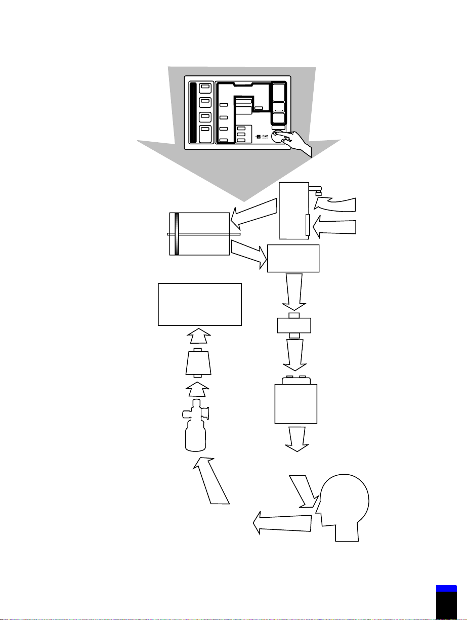
1.1 Functional description
By pressing keys and turning the knob on the ventilator keyboard, the operator
gives initial instructions and data to the ventilator
(Figure 1-1). The user interface microcontroller processes this information and
1-2
700 Series Ventilator Operator’s Manual G-061874-00 Rev. D (09/00)
Page 17

.
Introduction 1
...............................................................................
stores it in the ventilator’s memory. The breath delivery microcontroller uses this
stored information to control and monitor the flow of gas to and from the patient.
The 700 Series Ventilator uses a flow trigger to recognize patient effort. The
trigger monitors flow from the piston during exhalation. When the patient
inhales, patient circuit pressure drops very slightly below end-expiratory
pressure. At the same time, the piston moves forward to deliver flow to the
ventilator breathing circuit and maintain the preset PEEP/CPAP level. The level
of flow depends on the patient’s effort. If this flow exceeds the user-set level, the
ventilator triggers. By design, the ventilator attempts to maintain PEEP in the
presence of a circuit leak. Since a leak drives the piston to deliver flow to make
up for pressure losses, a circuit leak can require an increase in the flow trigger
level to avoid autocycling.
During exhalation, the ventilator’s piston retracts and draws air and oxygen into
the cylinder. The ventilator uses room air, which means the ventilator can operate
without a compressor or wall air source. Room air enters the ventilator through a
protected user-replaceable air intake filter just inside the ventilator cabinet. This
filter captures airborne particles.
Oxygen from a cylinder or wall supply enters the ventilator through a hose and
oxygen fitting (the fitting is available in several versions). Once inside the
ventilator, the oxygen is regulated to a pressure the ventilator can use, then mixed
with air, according to the selected % O
The flow-triggered piston/cylinder system and motor controller circuit control the
flow of gas to the patient. On the 760 Ventilator in PCV or PSV, the rate of flow
is also determined by the preset rise time factor. This system is designed with a
minute gap (about the size of a thin sheet of paper) between the piston and the
cylinder wall. This design eliminates the friction between the piston and cylinder,
allowing it to respond more rapidly than a “sealed” system.
.
2
A small amount of gas leaks through the gap between the piston and cylinder.
Ventilator software and a continuous forward motion of the piston compensate for
this leak.
The piston delivers the mixed air and oxygen through the inspiratory manifold
system, and out to the patient. The oxygen concentration and temperature of the
delivered gas are monitored here, using a galvanic oxygen sensor and a
thermistor. The galvanic sensor generates a voltage proportional to the partial
pressure of oxygen, from which the oxygen concentration is calculated. The
ventilator alarms if the monitored oxygen concentration is more than ten
percentage points above or below the % O
G-061874-00 Rev. D (09/00) 700 Series Ventilator Operator’s Manual
setting. The inspiratory manifold
2
1-3
Page 18

1 Introduction
system also includes a safety valve to relieve patient pressure if necessary (for
example, if the ventilator breathing circuit is kinked or occluded).
The patient system includes the components external to the ventilator that route
gas between the ventilator and the patient. These components include the
inspiratory filter (which protects against contamination between the ventilator
and patient), a humidification device, ventilator breathing circuit (the tubing
through which the gas travels), collector vial (which protects the exhalation
system from moisture in the exhaled gas, and can be emptied without losing
circuit PEEP), and an expiratory filter (which limits the bacteria in the patient’s
exhaled gas from escaping to room air or contaminating the ventilator).
1-4
700 Series Ventilator Operator’s Manual G-061874-00 Rev. D (09/00)
Page 19
.
Introduction 1
...............................................................................
+
-
740 Ventilator
Keyboard
Regulator
Piston/cylinder
system
Exhalation/
PEEP/CPAP
system
Filter
Oxygen
Room air
Inspiration
manifold
Inspiratory
filter
Gas intake
system
Expiratory
filter
Humidification
device
Collector
vial
Ventilator breathing
circuit (inspiratory limb)
Patient
Ventilator breathing
circuit (expiratory limb)
7-00017
Figure 1-1. Block diagram: 700 Series Ventilator function
G-061874-00 Rev. D (09/00) 700 Series Ventilator Operator’s Manual
1-5
Page 20

1 Introduction
The heated exhalation system monitors the flow of the patient’s exhaled gas using
a differential pressure transducer. The patient exhales through the exhalation
valve. During exhalation, the PEEP/CPAP system maintains user-selected
pressure in the ventilator breathing circuit.
Throughout the respiratory cycle, pressure transducers monitor inspiratory,
expiratory, and atmospheric pressures. The temperatures of the pneumatic
compartment and inspiratory gas are also monitored. Information from these
transducers is continuously used to update the calculations that control
ventilation. (Appendix F provides a diagram of the ventilator’s pneumatic system
and ventilator breathing circuit.)
Power to operate the ventilator comes from ac mains (wall) or battery power. The
power supply is designed to protect against excessive voltages, temperatures, or
current draws. A power cord retainer prevents the cord from accidental
disconnection.
The ventilator includes an internal battery, and accommodates an optional
external battery. Depending on the ventilator settings, battery backup power can
be supplied for up to 2 ½
the external battery. Both batteries are recharged during operation from ac power.
If both are installed, the external battery is used first when ac power is not
present. If the external battery is depleted or not installed, the internal battery
supplies power to the ventilator when ac power is not available. The keyboard
indicates the source of power and battery charge level of the internal battery at all
times.
hours using the internal battery, and up to 7 hours using
1-6
Emergency modes: The ventilator declares a ventilator inoperative (VENT INOP)
condition if a hardware failure or critical software error that could compromise
safe ventilation occurs. In case of a ventilator inoperative condition, the VENT
INOP indicator lights and the ventilator enters the safety valve open (SVO) state.
To correct a ventilator inoperative condition, the ventilator must be turned off,
then powered on again; at power-on, the operator must run extended self-test
(EST). The ventilator must pass EST before normal ventilation can resume.
The safety valve allows the patient to breathe room air unassisted when the
ventilator is in the SVO state. The ventilator remains in the SVO state until
power-on self-test (POST) verifies that power levels to the ventilator are
acceptable and that the motor controller and microcontrollers are functioning
correctly, and until the user has confirmed ventilator settings.
If the ventilator enters the SVO state and POST is not running, the SAFETY
VALVE OPEN indicator lights and a high-priority alarm sounds. The ventilator
enters the SVO state if it detects a hardware or software failure that could
700 Series Ventilator Operator’s Manual G-061874-00 Rev. D (09/00)
Page 21

.
Introduction 1
...............................................................................
compromise safe ventilation. In case of a malfunction that prevents software from
opening the safety valve, there is also an analog circuit that opens the safety valve
when system pressure exceeds 115 cmH
If the ventilator detects an occlusion or a continuous high inspiratory pressure
condition, it opens the safety and exhalation valves to vent excess pressure, then
shuts them and begins occlusion cycling mode. In occlusion cycling mode the
ventilator uses current settings except for those summarized in Table 1-2. If the
ventilator again detects an occlusion or continuous high pressure condition, it
again opens the safety and exhalation valves then resumes occlusion cycling
mode. If the operator presses the alarm reset key or the ventilator does not detect
an occlusion or continuous high pressure condition, it reverts to normal
ventilation using the most recently accepted settings.
Table 1-2: Changes to current settings in occlusion cycling mode
Setting Change to setting
O (113 hPa).
2
HIGH PRESSURE
alarm (VCV breath
type)
PEEP (all modes) Set to 0 cmH2O
(all modes) Set to 100%
%O
2
SPONT mode (PSV
breath type)
SUPPORT
PRESSURE (PSV
breath type)
SUPPORT
PRESSURE (PCV
breath type)
RISE TIME FACTOR
(PCV breath type)
G-061874-00 Rev. D (09/00) 700 Series Ventilator Operator’s Manual
Setto30cmH
Breaths are delivered at a rate of 12/min with an inspiratory time
of 2 seconds.
If less than 15 cmH
If 15 cmH
If less than 15 cmH
If 15 cmH2O or above: the current setting is used (no change).
Set to 70%
O
2
O:setto15cmH2O.
2
O or above: the current setting is used (no change).
2
O:setto15cmH2O.
2
1-7
Page 22
1 Introduction
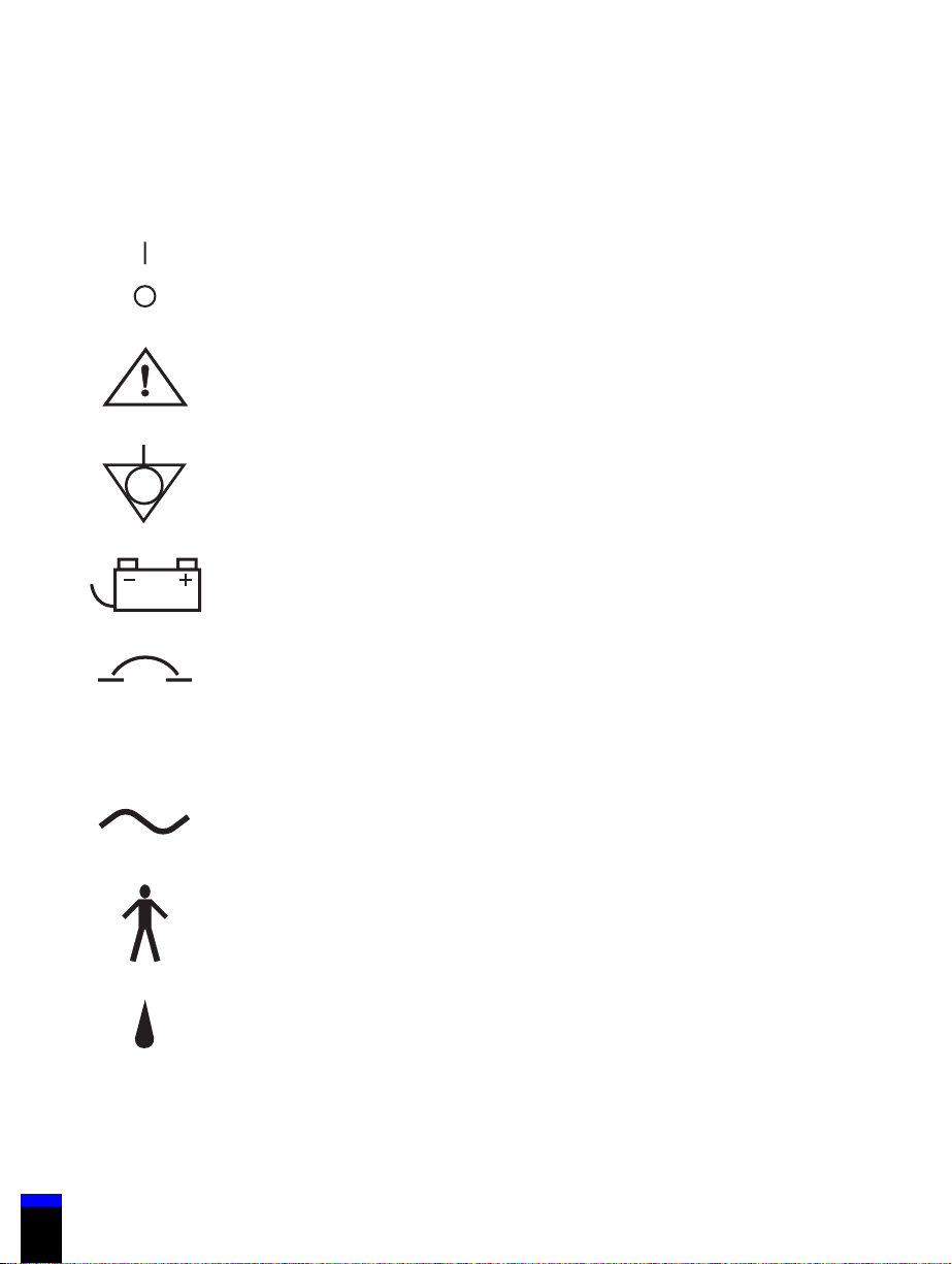
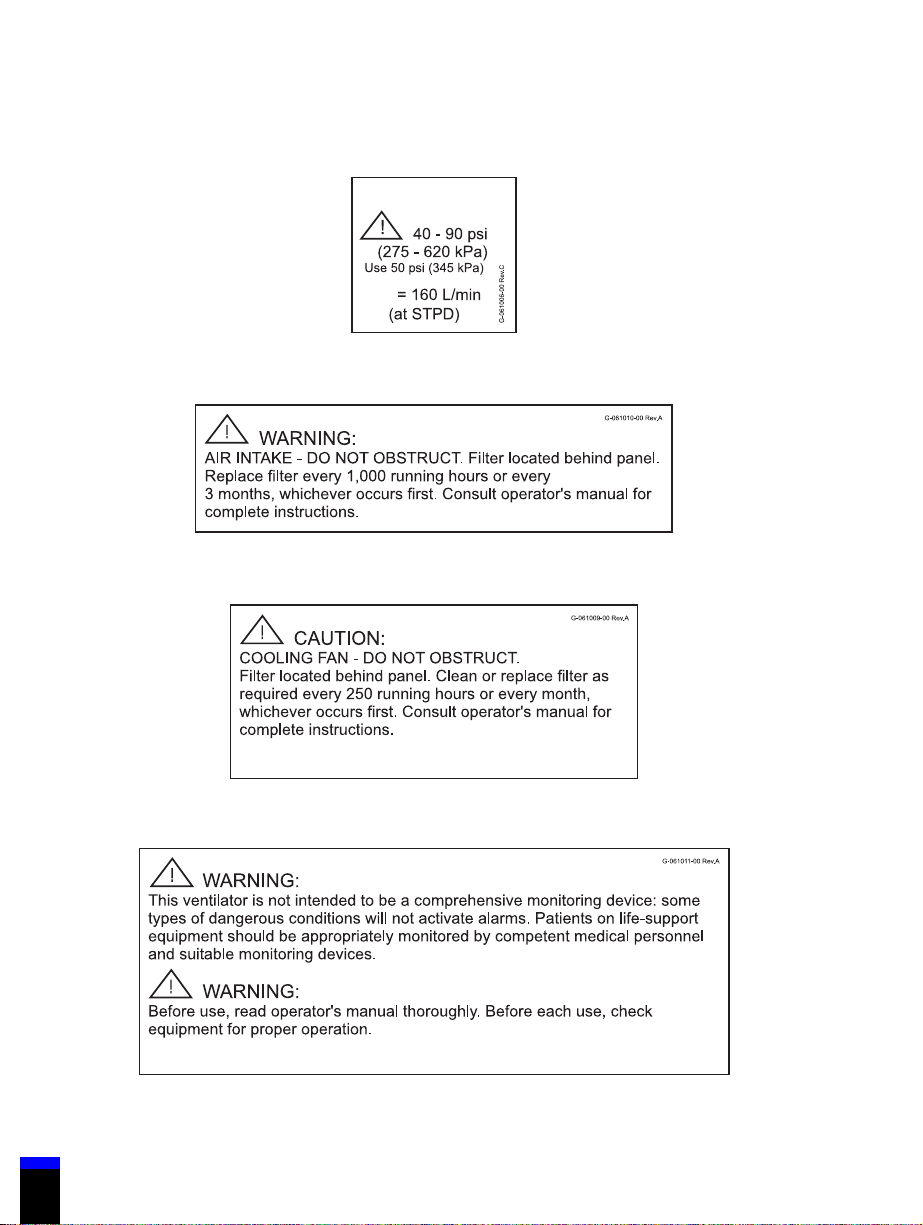
1.2 Symbols and labels
These symbols and labels appear on the 700 Series Ventilator System:
Power switch positions per IEC 601-1.”I” represents ON position; “O”
represents OFF position.
7-00421
Refer to manual per IEC 601-1. When this symbol appears on
product, it means “Refer to documentation for information.”
7-00418
Potential equalization point, per IEC 601-1
7-00416
External battery connection
7-00426
Circuit breaker
1-8
7-00414
Serial number
SN
ac current
7-00427
Type B equipment, per IEC 601-1
7-00415
Indicates the degree of protection provided by enclosure (drip-proof).
IPX1
7-00403
700 Series Ventilator Operator’s Manual G-061874-00 Rev. D (09/00)
Page 23
.
Introduction 1
...............................................................................
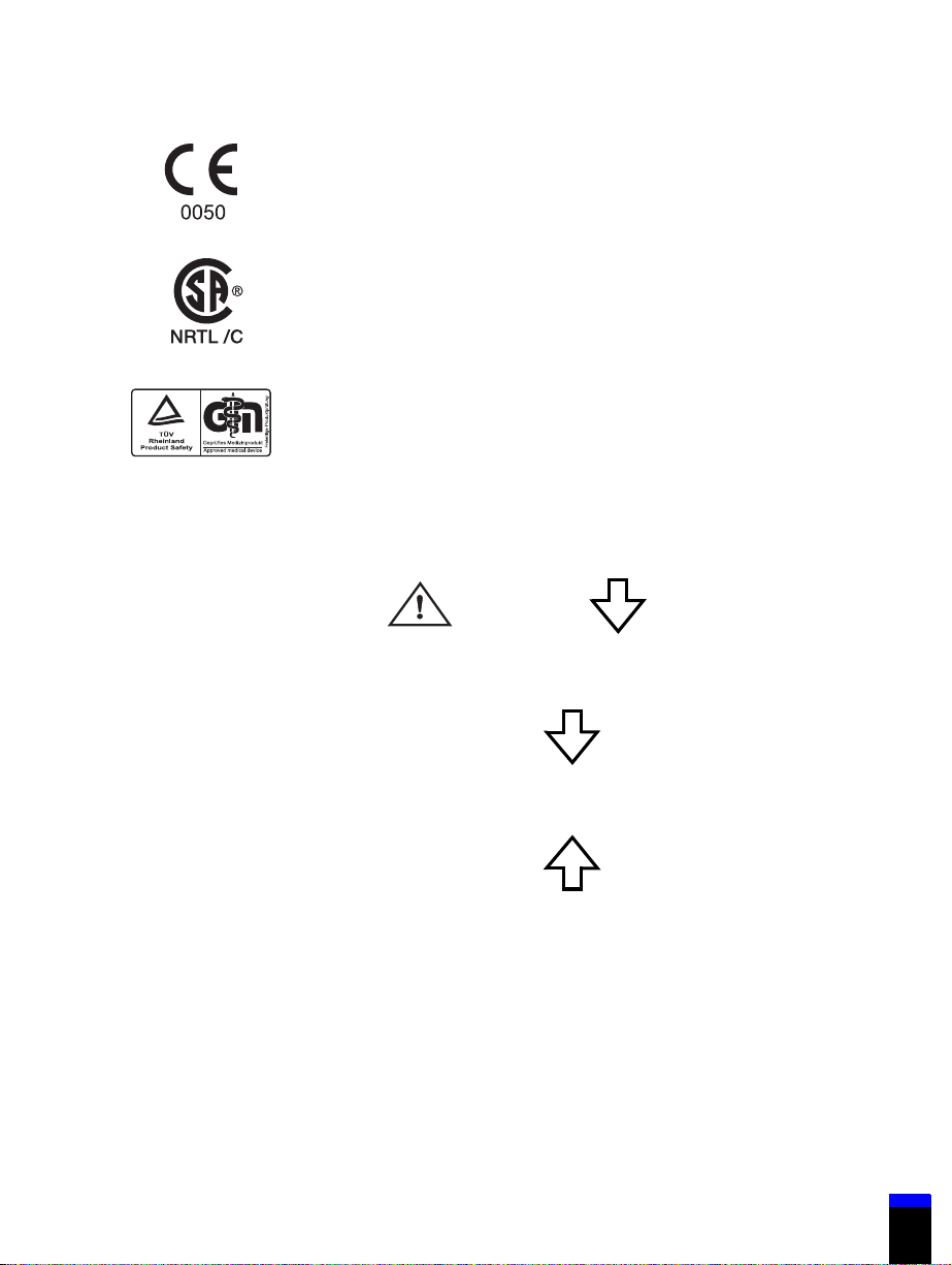
Signifies compliance with the Medical Device Directive, 93/42/EEC
7-00412
CSA and NRTL (Nationally Recognized Testing Laboratory)
certification, granted by CSA
8-00417
The TUV Rheinland logo signifies TUV Rheinland Type Test approval
to Annex III of the Medical Device Directive
7-00420
Exhaust port connector
EXHAUST
Inspiratory limb connector
TO
PATI EN T
Expiratory limb connector
FROM
PATI EN T
G-061874-00 Rev. D (09/00) 700 Series Ventilator Operator’s Manual
1-9
Page 24
1 Introduction
Oxygen inlet port label
O
2
.
V
max
61006
Air intake label
61010
Cooling fan label
General life support equipment warning label
1-10
700 Series Ventilator Operator’s Manual G-061874-00 Rev. D (09/00)
61009
61011
Page 25
.
Introduction 1
...............................................................................
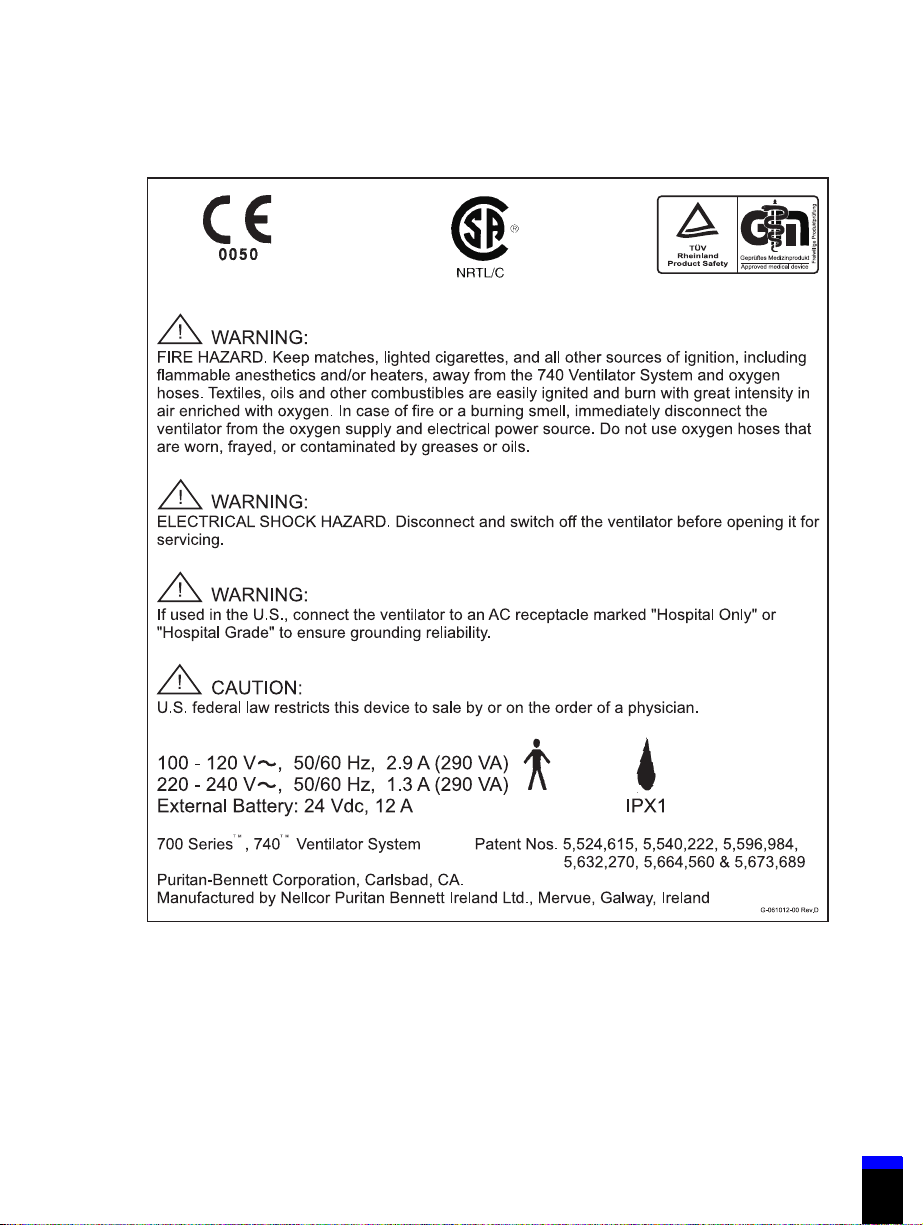
740 Ventilator back panel label
61012
G-061874-00 Rev. D (09/00) 700 Series Ventilator Operator’s Manual
1-11
Page 26
1 Introduction
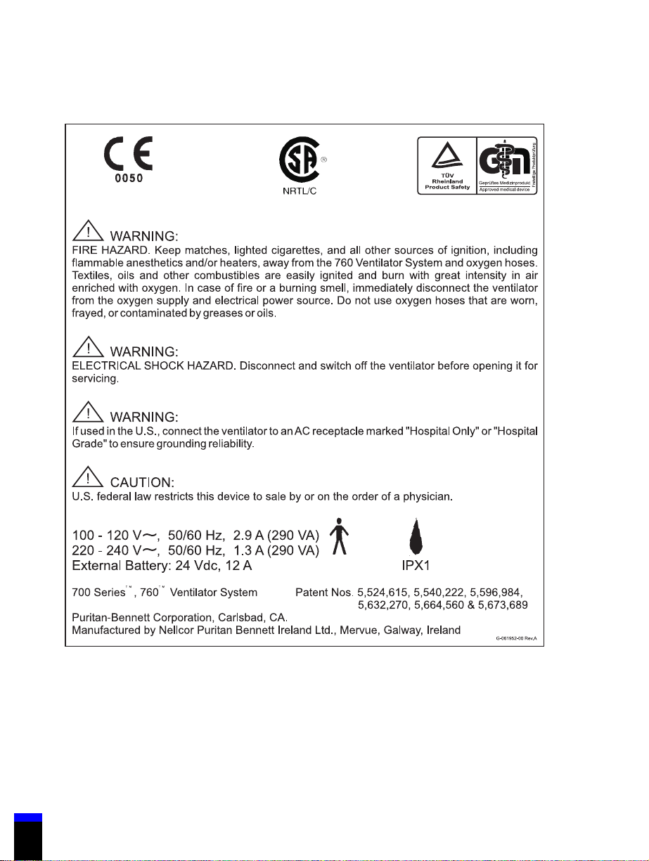
760 Ventilator back panel label
1-12
61952
700 Series Ventilator Operator’s Manual G-061874-00 Rev. D (09/00)
Page 27
.
Introduction 1
...............................................................................
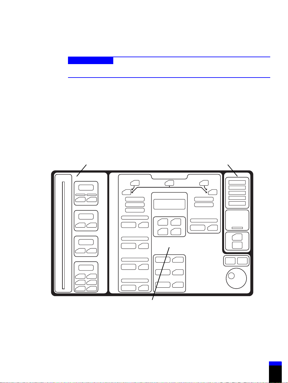
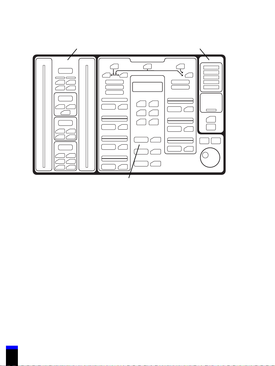
1.3 Keyboard
Caution
To avoid damaging the keyboard, do not press on it with sharp objects.
The keyboard (Figure 1-2 shows the 740 keyboard and Figure 1-3 shows the 760
keyboard) is grouped into three sections:
• VENTILATOR SETTINGS: Where you set breath delivery variables.
• PATIENT DATA: Where you set alarm limits and view the monitored
pressures, breath timing, and volumes.
• VENTILATOR STATUS: Where you see the alarm status and operating
condition of the ventilator.
Patient data Ventilator status
Ventilator settings
Figure 1-2. 740 Ventilator System keyboard
G-061874-00 Rev. D (09/00) 700 Series Ventilator Operator’s Manual
7-00048
1-13
Page 28
1 Introduction
Patient data Ventilator status
1-14
Ventilator settings
7-00123
Figure 1-3. 760 Ventilator System keyboard
1.3.1 VENTILATOR SETTINGS
The VENTILATOR SETTINGS section of the keyboard allows you to select the
ventilation mode, breath type, and settings. For more detail on ventilation modes
and breath delivery, see Appendix D.
To change the mode and settings, select the mode, then the breath type, and then
the ventilator settings. The keys flash during setup and mode changes to ensure
that you review all pertinent settings. The keyboard is designed to minimize
accidental or unintentional changes.
Table 1-3 summarizes the functions of the keys, knob, and indicators in the
VENTILATOR SETTINGS section of the keyboard. Ventilator settings are also
limited by these breath delivery boundaries:
• I:E ratio £ 4:1 for PCV (760 Ventilator only), £ 3:1 for all other breath types
• Inspiratory time = 0.2 to 8 seconds (excluding plateau)
• Expiratory time ³ 0.2 seconds
700 Series Ventilator Operator’s Manual G-061874-00 Rev. D (09/00)
Page 29

.
Introduction 1
...............................................................................
• PEEP/CPAP + SUPPORT PRESSURE or INSPIRATORY PRESSURE £ 80
cmH
O (80 hPa)
2
NOTE:
Maximum SUPPORT PRESSURE is 70 cmH
INSPIRATORY PRESSURE is 80 cmH
2
• SUPPORT PRESSURE or INSPIRATORY PRESSURE + PEEP/CPAP
< HIGH PRESSURE - 2 cmH
O(2hPa)
2
• HIGH PRESSURE (in A/C and SIMV modes) > PEEP/CPAP +
7cmH
O(7hPa)
2
• HIGH PRESSURE (in SPONT mode) > PEEP/CPAP + SUPPORT
PRESSURE + 2 cmH
O(2hPa)
2
• HIGH PRESSURE > LOW INSP PRESSURE
• Minute volume £ 50 L/min at an I:E ratio of 2:1
Table 1-3: 700 Series Ventilator keyboards: VENTILATOR SETTINGS
O.
O, maximum
2
Key/indicator Specifies... Range
Mode/breath type settings
A/C Assist/control mode VCV (volume control ventilation)
and PCV (pressure control
ventilation) breath types.
(PCV available on 760 Ventilator
only.)
SIMV Synchronous intermittent
mandatory ventilation mode
SPONT Spontaneous mode PSV breath type
VCV VCV breath type VCV available on 740 and 760
PCV PCV breath type PCV available on 760 Ventilator
G-061874-00 Rev. D (09/00) 700 Series Ventilator Operator’s Manual
VCV, PCV (760 only), and PSV
(pressure support ventilation)
breath types.
Ventilators in A/C or SIMV
modes.
only in A/C or SIMV modes.
1-15
Page 30

1 Introduction
Table 1-3: 700 Series Ventilator keyboards: VENTILATOR SETTINGS (continued)
Key/indicator Specifies... Range
PSV PSV breath type PSV available in SIMV or
SPONT modes.
Mandatory (VCV) settings
RESPIRATORY
RATE
TIDAL
VOLUME
PEAK FLOW Maximum flow of gas delivered
PLATEAU (s) Length of inspiratory pause after a
Mandatory (PCV) settings (760 Ventilator only)
RESPIRATORY
RATE
The minimum number of
mandatory breaths the patient
receives per minute. During apnea
ventilation the minimum
RESPIRATORY RATE setting is 6 /
minute.
Volume delivered to the patient
during a mandatory breath,
compliance-compensated and
corrected to body temperature and
pressure, saturated (BTPS).
during a mandatory breath (BTPS).
(Combined with tidal volume, peak
flow defines the active portion of
inspiratory time.)
mandatory breath has been
delivered, during which no gas is
delivered.
The minimum number of
mandatory breaths the patient
receives per minute. During apnea
ventilation the minimum
RESPIRATORY RATE setting is 6 /
minute.
1to70/minute
Accuracy: ± (0.1 + 1%) /minute
40 to 2000 ml
Accuracy: ± (10 ml + 10% of
setting)
3to150L/min
Accuracy: ± (5 + 10% of setting)
L/min
0.0to2.0second
Accuracy: ± 0.05 second
1to70/minute
Accuracy: ± (0.1 + 1%) /minute
INSPIRATORY
PRESSURE
(760 only)
1-16
Pressure above PEEP during the
inspiratory phase of a PCV breath.
700 Series Ventilator Operator’s Manual G-061874-00 Rev. D (09/00)
5to80cmH
Accuracy: ± (3 + 2.5% of setting)
O
cmH
2
O(5to80hPa)
2
Page 31

.
Introduction 1
...............................................................................
Table 1-3: 700 Series Ventilator keyboards: VENTILATOR SETTINGS (continued)
Key/indicator Specifies... Range
TI/I:E RATIO
(760 only)
RISE TIME
FAC TOR
(760 only)
NOTE:
To help determine the correct setting for inspiratory time, during PCV the message
window displays peak inspiratory flow, end inspiratory flow, and end exhalation flow
in L/min.
YoucanusetheMENUkeyto
select inspiratory time (T
ratio as the breath timing setting for
a PCV breath. You can change the
selected breath timing setting (T
I:E ratio), but the setting remains
constant when you change the
respiratory rate in PCV.
Selecting I:E ratio makes the set
ratio of inspiratory time to
expiratory time for a PCV breath.
Thetimeforinspiratorypressureto
rise from 0 to 95% of the target
pressure level during a PCV
breath.
A setting of 100 = a 100-ms rise
time, and a setting of 5 = 80% of
the inspiratory time or 2500 ms,
whichever is less.
When you adjust this setting, the
message window shows the actual
time (in seconds) to reach 95% of
target pressure.
)orI:E
I
or
I
Inspiratory time (T
0.2 to 8 seconds
Accuracy: ± 0.05 second
I:E ratio:
Accuracy: ± (0.1 + 2%)
5to100
£ 4:1
):
I
G-061874-00 Rev. D (09/00) 700 Series Ventilator Operator’s Manual
1-17
Page 32

1 Introduction
Table 1-3: 700 Series Ventilator keyboards: VENTILATOR SETTINGS (continued)
Key/indicator Specifies... Range
Spontaneous (PSV) settings
SUPPORT
PRESSURE
RISE TIME
FAC TOR
(760 only)
Pressure above PEEP maintained
during spontaneous inspiration.
Support pressure is terminated
when inspiratory flow falls to 25%
of peak inspiratory flow, or to the
exhalation sensitivity setting (760
only), or 10 L/min or 25% of peak
flow, whichever is lower (740 only).
Maximum inspiratory time is 3.5
seconds for adults, and 2.5
seconds for pediatric patients.
Thetimeforinspiratorypressureto
rise from 0 to 95% of the target
pressure level during a PSV breath.
A setting of 100 = a 100-ms rise
time, and a setting of 5 = 80% of
the inspiratory time or 1500 ms
(when adult ventilator breathing
circuit is selected) or 600 ms (when
pediatric circuit is selected),
whichever is less.
When you adjust this setting, the
message window shows the actual
time (in seconds) to reach 95% of
target pressure.
0to70cmH
Accuracy: ± (3 + 2.5% of setting)
O
cmH
2
5to100
O(0to70hPa)
2
1-18
700 Series Ventilator Operator’s Manual G-061874-00 Rev. D (09/00)
Page 33

.
Introduction 1
...............................................................................
Table 1-3: 700 Series Ventilator keyboards: VENTILATOR SETTINGS (continued)
Key/indicator Specifies... Range
EXH
SENSITIVITY
(760 only)
Common settings
PEEP/CPAP Positive end expiratory pressure/
The percent of peak expiratory flow
at which the ventilator cycles from
inspiration to exhalation for
spontaneous breaths. The flow at
which the ventilator cycles from
inspiration to exhalation for PSV
breaths. Exhalation begins when
the inspiratory flow is less than the
set value.
To help set EXH SENSITIVITY
appropriately, the peak inspiratory
flow and end inspiratory flow are
displayed in the message window
in PSV. (To ensure accurate
estimates of these flows, it is
important to run SST so that tubing
compliance calculations are
correct.)
continuous positive airway
pressure. Minimum pressure
maintained during inspiratory and
expiratory phases.
1to80%
0to35cmH
Accuracy:
± (2 cmH
O + 4% of setting)
2
O(0to35hPa)
2
TRIGGER
SENSITIVITY
(L/min)
%O
2
Inspiratory flow required to trigger
the ventilator to deliver a breath.
Percentage of inspired oxygen of
the gas delivered to the patient.
1to20L/min
21 to 100%
Accuracy: ± 3% full scale
NOTE:
It may take several minutes for the oxygen percentage to
stabilize.
G-061874-00 Rev. D (09/00) 700 Series Ventilator Operator’s Manual
1-19
Page 34

1 Introduction
Table 1-3: 700 Series Ventilator keyboards: VENTILATOR SETTINGS (continued)
Key/indicator Specifies... Range
Other keys, knobs, and indicators
APNEA
PA RA MS k ey
AllowsyoutoselectVCVorPCV(760 Ventilator only) apnea ventilation,
and the apnea ventilation settings. The apnea interval is adjustable from
10 to 60 seconds. Apnea ventilation is available in all modes. For apnea
parameter ranges, see mandatory VCV settings and mandatory PCV
(760 Ventilator only) settings.
MENU Allows you to view active and reset alarms, run SST and EST, adjust
certain settings (including alarm volume, PCV timing, volume bar graph
display, endotracheal tube size, and date and time), access oxygen
sensor functions (calibrate, enable or disable % O
alarm limits, and
2
enable or disable display of oxygen sensor reading), enter standby
mode, view battery information, display software revision, display
service information, and enter EasyNeb nebulizer functions. (Section 6
tells you how to use the menu function.)
100% O
2
Switches the % O2to 100% for 2 minutes, then returns to the current %
setting. The 2-minute interval restarts every time you press 100%
O
2
O
. Once the 100% O2has started, you can press CLEAR to stop the
2
maneuver (unless you have entered a MENU key function or selected a
setting).
MANUAL INSP Delivers one mandatory breath to the patient according to the current
mandatory settings (in A/C or SIMV) or the current apnea parameters (in
SPONT). You can deliver a MANUAL INSP at any time during the
exhalation phase of a breath as long as the exhaled flow is less than
30% of the peak exhaled flow, except during apnea ventilation.
1-20
700 Series Ventilator Operator’s Manual G-061874-00 Rev. D (09/00)
Page 35

.
Introduction 1
...............................................................................
Table 1-3: 700 Series Ventilator keyboards: VENTILATOR SETTINGS (continued)
Key/indicator Specifies... Range
EXP PAUSE
(760 only)
Allows you to measure the patient’s auto-PEEP. An EXP PAUSE
maneuver causes the ventilator to close the exhalation valve at the end
of the expiratory phase, and not deliver the next mandatory breath. At
the end of the maneuver, the message window shows the calculated
value for auto-PEEP (expiratory pressure at the beginning of the
maneuver minus expiratory pressure at the end of the maneuver) and
total PEEP for 30 seconds.
The message window shows the end expiratory flow in L/min at the
beginning of each breath. If there is expiratory flow when the ventilator
delivers the next breath, auto-PEEP is present.
The EXP PAUSE continues as long as you hold down the key, and
should last only until expirator y pressure stabilizes. An EXP PAUSE
maneuver ends when you release the key, the patient initiates a breath,
an alarm occurs, the expiratory phase (including the maneuver) lasts
more than 20 seconds, or the ventilator detects a leak.
Auto-PEEP:
Range: 1 to 35 cmH
Accuracy: ± (1 cmH
The EXP PAUSE maneuver is unavailable when the RESPIRATORY
RATE setting is less than 3 /minute.
O.
2
O + 3% of reading).
2
G-061874-00 Rev. D (09/00) 700 Series Ventilator Operator’s Manual
1-21
Page 36

1 Introduction
Table 1-3: 700 Series Ventilator keyboards: VENTILATOR SETTINGS (continued)
Key/indicator Specifies... Range
Other keys, knobs, and indicators (continued)
INSP PAUSE
(760 only)
Allows you to measure the patient’s compliance and resistance. An
extended inspiratory pause also allows you to expand the patient’s lungs
forupto10seconds.
Pressing INSP PAUSE momentarily causes the ventilator to wait until
the end of the inspiratory phase of the current or next mandatory breath
(in SPONT mode, the ventilator delivers a mandatory breath using the
MANUAL INSP key according to the apnea settings), stop breath
delivery, and keep the exhalation valve closed. The INSP PAUSE
continues until the ventilator detects a stable plateau pressure or 2
seconds have elapsed. An INSP PAUSE maneuver ends when a stable
plateau is reached or an alarm occurs.
Pressing INSP PAUSE for 2 or more seconds after the pause begins
causes the ventilator to deliver an inspiratory pause for as long as you
hold down the key. An extended INSP PAUSE maneuver ends when you
release the key or 10 seconds have elapsed.
You can press CLEAR or release the INSP PAUSE key at any time to
cancel an INSP PAUSE maneuver, and alarms cancel the maneuver.
At the end of the breath, the message window shows the calculated
value for compliance and resistance (if the mandatory breath was a VCV
breath) or compliance (if the mandatory breath was a PCV breath) for 30
seconds.
Compliance:
Range: 1 to 150 mL/H
Accuracy: ± (1 mL/cmH
O.
2
O + 20% of reading).
2
Resistance:
Range: 0 to 150 cmH
Accuracy: ± (3 cmH
O/L/second.
2
O/L/second + 20% of reading).
2
CLEAR Pressing CLEAR before accepting a setting cancels the proposed
setting. Pressing CLEAR does not cancel accepted settings.
Pressing CLEAR twice returns the ventilator to its previous state (unless
you have entered a MENU key function that requires you to press
CLEAR more times).
Pressing CLEAR during a 100% O2maneuver cancels the maneuver.
1-22
700 Series Ventilator Operator’s Manual G-061874-00 Rev. D (09/00)
Page 37

.
Introduction 1
...............................................................................
Table 1-3: 700 Series Ventilator keyboards: VENTILATOR SETTINGS (continued)
Key/indicator Specifies... Range
Other keys, knobs, and indicators (continued)
ACCEPT Makes changes to settings effective. If you don’t press ACCEPT within
30 seconds of proposing a new setting, the user interface returns to its
previous state.
Knob Adjusts the value of a setting or selects a menu option. A setting value
that flashes means that the knob is linked to that setting. Turning the
knob clockwise increases the value, and turning the knob
counterclockwise decreases the value.
CURRENT Lights when the ventilator is operating according to the displayed
settings, or during apnea ventilation. (There is one indicator for
mandatory breaths, and one for spontaneous breaths.)
PROPOSED Lights when you propose a mode or breath type, or you are setting
apnea parameters. Once a proposed setting is accepted, it becomes
effective at the next breath.
APNEA
PA RA MS
indicator
Message
window
G-061874-00 Rev. D (09/00) 700 Series Ventilator Operator’s Manual
Lights when apnea ventilation is active.
Lights with PROPOSED indicator when you are setting apnea
parameters, and both indicators turn off once apnea parameters are
accepted.
Shows up to four lines of information (20 characters per line).
First line: Reserved for the highest-priority active or autoreset alarm. On
the 760 Ventilator only, if no alarm is active and the display of the oxygen
sensor reading is enabled, the % O
VCV is the current or proposed breath type and there are no active or
autoreset alarms, shows the selected VCV flow pattern (ramp or
square).
Second line: Information about the menu function or settings, alarm
silence time remaining, or current date and time. During normal
ventilation, shows “Flow (L/min).”
Third and fourth lines: Reserved for other messages. For every breath
type, peak and end inspiratory flows are displayed on the third line, and
end expiratory flow is displayed on the fourth line (except that inspiratory
flow is not displayed during VCV breaths or VCV apnea ventilation).
is displayed here. Otherwise, if
2
1-23
Page 38

1 Introduction
1.3.2 PATIENT DATA
The PATIENT DATA section of the keyboard allows you to view the pressure,
breath timing, and volume of the patient’s breath. You can also view the alarm
settings. A lighted key indicates that a measurement is selected, and its value
appears in the display window. Values are continuously displayed and updated
during ventilation.
Table 1-4 summarizes the functions of the keys and indicators in the PATIENT
DATA section of the keyboard.
Table 1-4: 700 Series Ventilator keyboards: PATIENT DATA
Key/
indicator
Pressure
MEAN
PRESSURE
PEAK
PRESSURE
PLATEAU
PRESSURE
(760 only)
PEEP/CPAP
(760 only)
Function Range
Shows the calculated value of ventilator
breathing circuit pressure over an entire
respiratory cycle. Updated at the
beginning of each breath.
Shows the maximum pressure measured
during inspiration. Updated at the
beginning of each expiratory phase.
(Default pressure display.)
Shows the pressure measured at the end
of the plateau period of a mandatory
inspiration (whether the inspiration is in a
regular VCV breath or is part of an
inspiratory pause maneuver). Updated at
the beginning of each expiratory phase.
The PRESSURE display shows a blank if
the ventilator does not detect a stable
plateau pressure.
Shows the pressure measured at the
expiratory limb before any inspiratory
effort. Updated at the beginning of each
inspiratory phase.
0to99cmH
Accuracy:
± (3 + 4% of reading) cmH2O
0to140cmH
Accuracy:
± (3 + 4% of reading) cmH
0to140cmH
Accuracy:
± (3 + 4% of reading) cmH
0to140cmH
Accuracy:
± (3 + 4% of reading) cmH
O(0to99hPa)
2
O(0to140hPa)
2
O(0to140hPa)
2
O(0to140hPa)
2
2
2
2
O
O
O
1-24
700 Series Ventilator Operator’s Manual G-061874-00 Rev. D (09/00)
Page 39

.
Introduction 1
...............................................................................
Table 1-4: 700 Series Ventilator keyboards: PATIENT DATA (continued)
Key/
indicator
Breath timing
RATE (/min) Shows the calculated value of the total
respiratory rate, based on the previous 60
seconds or 8 breaths (whichever interval
is shorter). Updated at the beginning of
each breath. (Default breath timing
display.)
The calculation is reset (and display is
blank) when ventilation starts, when
apnea ventilation starts or autoresets,
when you change the mode, breath type,
or RESPIRATORY RATE setting, and
whenyoupressthealarmresetkey.
I:E RATIO Shows the ratio of measured inspiratory
time to measured expiratory time.
Updated at the beginning of each breath.
INSP
TIME(s)
(760 only)
The measured inspiratory time, including
breaths that are truncated due to a HIGH
PRESSURE alarm. Updated at the
beginning of each expiratory phase.
Function Range
1 to 199 /minute
Accuracy:
± (0.1 +1% of reading)/minute
1:99.9 to 9.9:1
Accuracy:
± (0.1 + 2%)
0.1 to 9.90 seconds
Accuracy:
± 0.05 seconds
Vol ume
EXHALED
VOLUME
(ml)
G-061874-00 Rev. D (09/00) 700 Series Ventilator Operator’s Manual
Shows the patient’s measured expiratory
tidal volume averaged over the last 5
breaths (for A/C VCV breaths, ventilatorinitiated PCV breaths, and PCV apnea
breaths) or for the just-completed breath
(for all other breaths). Corrected to BTPS
and compliance-compensated. Updated
at the beginning of each inspiration.
(Default volume display.)
The calculation is reset when ventilation
starts, when apnea ventilation starts or
autoresets, when you change the mode or
breath type, and when you press the
alarm reset key.
0to9L
Accuracy:
± (10 ml + 10% of reading)
1-25
Page 40

1 Introduction
Table 1-4: 700 Series Ventilator keyboards: PATIENT DATA (continued)
Key/
indicator
Volume (continued)
TOTAL
MINUTE
VOLUME (L)
DELIVERED
VOLUME
(ml)
(760 only)
SPONT
MINUTE
VOLUME (L)
(760 only)
Shows the patient’s measured expiratory
minute volume, based on the previous 60
seconds or 8 breaths (whichever interval
is shorter). Updated at the beginning of
each breath.
The calculation is reset when ventilation
starts, when apnea ventilation starts or
autoresets, when you change the mode or
breath type, and when you press the
alarm reset key.
Shows the measured inspiratory tidal
volume for the just-completed PCV or PSV
breath. Corrected to BTPS and
compliance-compensated. Updated at the
beginning of each inspiration for PCV and
PSV breath types.
Shows the patient’s measured expiratory
minute volume for all spontaneous
breaths, based on the previous 60
seconds or 8 breaths (whichever interval
is shorter). Updated at the beginning of
each breath.
The calculation is reset when ventilation
starts, when apnea ventilation starts or
autoresets, when you change the mode or
breath type, and when you press the
alarm reset key.
Function Range
0to99L
Accuracy:
± (10 ml + 10% of reading)
0 to 3000 ml
Accuracy:
± (10 ml + 10% of reading)
0to99L
Accuracy:
± (10 ml + 10% of reading)
1-26
700 Series Ventilator Operator’s Manual G-061874-00 Rev. D (09/00)
Page 41

.
Introduction 1
...............................................................................
Table 1-4: 700 Series Ventilator keyboards: PATIENT DATA (continued)
Key/
indicator
Alarm settings
HIGH RATE An active alarm indicates that measured
respiratory rate is higher than the alarm
setting.
HIGH TIDAL
VOLUME
LOW INSP
PRESSURE
LOW TIDAL
VOLUME
HIGH
PRESSURE
An active alarm indicates that exhaled
volume for three out of four consecutive
breaths was above the alarm setting.
An active alarm indicates that monitored
circuit pressure is below the alarm setting
at the end of inspiration. Inactive in for any
spontaneous breath.
An active alarm indicates that delivered
volume for three out of four consecutive
breaths were below the alarm setting. (If
this alarm is set to 0 ml and breath type is
PCV, an active alarm indicates that
delivered volume is less than 3 ml for three
out of four consecutive breaths.)
An active alarm indicates that two
consecutive breaths were truncated
because circuit pressure reached the
alarm setting.
Function Range
3 to 100 /minute
Accuracy:
± (0.1 +1% of setting)/minute
20 to 6000 ml
Accuracy:
± (10 ml + 10% of setting)
3to60cmH
Accuracy:
± (1 + 3% of setting)
0 to 2000 ml
Accuracy:
± (10 ml + 10% of setting)
10 to 90 cmH
(10to90hPa)
Accuracy:
± (1 + 3% of setting)
O(3to60hPa)
2
O
2
LOW
MINUTE
VOLUME
G-061874-00 Rev. D (09/00) 700 Series Ventilator Operator’s Manual
An active alarm indicates that monitored
minute volume is less than the alarm
setting, based on an eight-breath running
average or the previous minute, whichever
is less.
0to50L
Accuracy:
± (10 ml + 10% of setting)
1-27
Page 42

1 Introduction
Table 1-4: 700 Series Ventilator keyboards: PATIENT DATA (continued)
Key/
indicator
Other indicators
Pressure bar
graph
Volume bar
graph
(760 only)
MAND Lights at the start of each breath to
Shows real-time pressures in centimeters
of water (cmH2O) or hectopascals (hPa).
LEDs show the current HIGH PRESSURE
alarm setting and the peak pressure of the
last breath during exhalation.
Shows real-time exhaled volume in
milliliters (ml). Volumes are compliancecompensated and corrected to BTPS.
The active scale is determined by the
HIGH TIDAL VOLUME alarm setting.
LEDs show the current HIGH TIDAL
VOLUME and LOW TIDAL VOLUME
alarm settings. You can use the MENU key
to enable or disable the volume bar graph.
During exhalation, LEDs show the
maximum exhaled volume of the last
breath.
indicate a ventilator- or operator-initiated
(time or manually triggered) mandatory
breath is being delivered.
Function Range
-10to90cmH
(-10to90hPa)
Resolution: 1 cmH2O(1hPa)
If HIGH TIDAL VOLUME
setting < 500 ml: 0 to 500 ml
Resolution: 5 ml
If HIGH TIDAL VOLUME
setting >
Resolution: 20 ml
Not applicable
O
2
500ml:0to2000ml
ASSIST Lights at the start of each breath to
indicate a patient-initiated mandatory (flow
triggered) breath is being delivered.
SPONT Lights at the start of each breath to
indicate a patient-initiated spontaneous
(flow triggered) breath is being delivered.
1.3.3 VENTILATOR STATUS
The VENTILATOR STATUS section of the keyboard shows the operating
condition of the ventilator, and is continuously updated during operation. Table
1-28
700 Series Ventilator Operator’s Manual G-061874-00 Rev. D (09/00)
Not applicable
Not applicable
Page 43

.
Introduction 1
...............................................................................
1-5 summarizes the functions of the keys and indicators in the VENTILATOR
STATUS section of the keyboard.
Table 1-5: 700 Series Ventilator keyboards: VENTILATOR STATUS
Key/indicator Color Function
ALARM Red
(high priority)
CAUTION Yellow
(medium priority)
NORMAL Green Lights when no alarm condition is present.
VENT INOP Red
(high priority)
SAFETY VALVE
OPEN
Red
(high priority)
Flashes when a high-priority alarm is active. A
repeating sequence of three, then two beeps
sounds. Lights steadily when a high-priority
alarm has been autoreset.
Flashes when a medium-priority alarm is active.
A repeating sequence of three beeps sounds.
Lights steadily when a medium-priority alarm
has been autoreset.
Lights to indicate that the ventilator is
inoperative, and the ventilator safety valve is
open. A qualified service technician must run
and pass the extended self-test (EST) before
normal ventilation can resume.
If the condition that caused the safety valve to
open no longer exists, and the VENT INOP
indicator is off, press the alarm reset key to
resume ventilation.
Lights when the ventilator’s safety valve and
exhalation valve open and only room air is
available to the patient.
Can indicate that the ventilator is inoperative, or
there is an occlusion in the ventilator breathing
circuit. If possible, the message window shows
the alarm that triggered the safety valve open
condition and how much time has elapsed since
the last breath was triggered.
ON AC/
BATTERY
CHARGING
ON INTERNAL
BATTERY
G-061874-00 Rev. D (09/00) 700 Series Ventilator Operator’s Manual
Green Lights when the ventilator is running on ac
power and the battery is charging.
Yellow Flashes when the ventilator is running on the
internal battery.
1-29
Page 44
1 Introduction
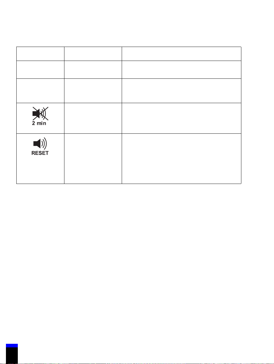
Table 1-5: 700 Series Ventilator keyboards: VENTILATOR STATUS (continued)
Key/indicator Color Function
ON EXTERNAL
BATTERY
INTERNAL
BATTERY
LEVEL
7-00423
7-00424
Yellow Flashes when the ventilator is running on the
external battery.
Green Shows the relative charge level of the internal
battery.
Ye l l o w Alarm silence: Silences the alarm sound for 2
minutes from the most recent key press.
Not applicable Alarm reset: Reestablishes all alarm indicators,
cancels the alarm silence period, and resets the
patient data displays. If the condition that
caused the alarm still exists, the alarm
reactivates. Cancels apnea ventilation, if active.
Reestablishes previous settings and ventilation
resumes, unless the ventilator is inoperative.
1-30
700 Series Ventilator Operator’s Manual G-061874-00 Rev. D (09/00)
Page 45

SECTION
Setting up the ventilator 2
2
..............................................................................
This section tells you how to set up the ventilator, including:
• Connecting and using the internal and external batteries
• Connecting the electrical supply
• Connecting the oxygen supply
• Connecting the ventilator breathing circuit
• Installing the collector vial
• Installing the flex arm
• Installing the humidifier
• Using the ventilator cart
Warning
• To avoid tipping or damaging the ventilator, do not stack other
equipment on the ventilator. 700 Series Ventilators are designed
to be mounted on either a cart or a shelf by a qualified service
technician. When lifting the ventilator, lift from the base, and use
assistance and appropriate safety precautions. Figure 2-1 shows
proper lifting technique.
• To avoid the possibility of injury to the patient and to ensure
proper ventilator operation, do not attach any device to the port
labeled “EXHAUST” unless the device is specifically authorized
by Mallinckrodt.
• To minimize the increased risk of fire due to an oxygen-enriched
environment, do not use the ventilator in a hyperbaric chamber.
• To avoid raising the oxygen concentration of room air, use the
ventilator in an adequately ventilated room.
Caution
Do not obstruct the cooling fan
G-061874-00 Rev. D (09/00) 700 Series Ventilator Operator’s Manual
.
2-1
Page 46
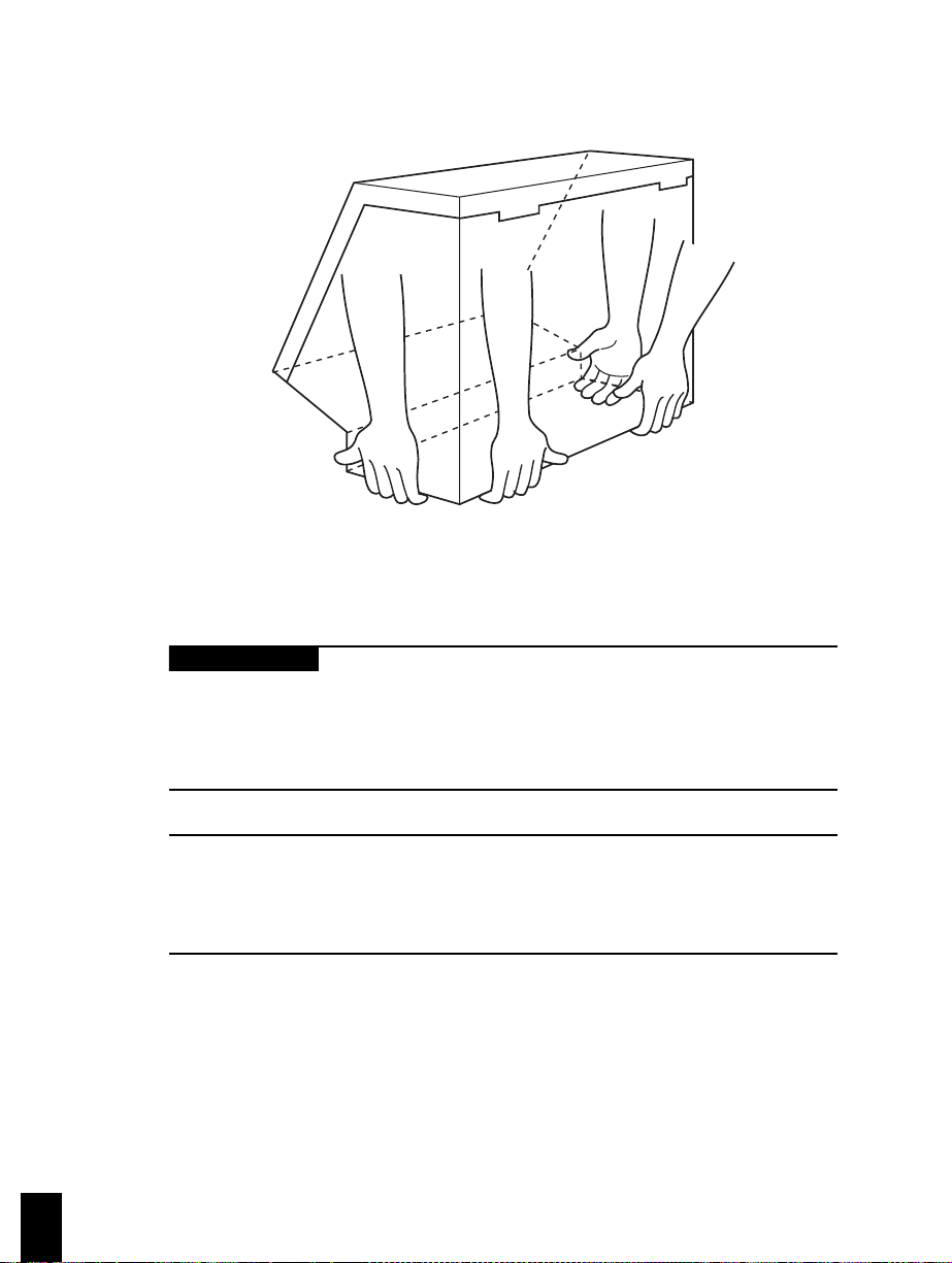
2 Setting up the ventilator
Use two people to lift
Lift ventilator from base only
7-00053
Figure 2-1. Lifting the ventilator
2.1 Connecting and using internal and external batteries
Warning
A Mallinckrodt battery must always be installed in the ventilator.
Without a battery, the ventilator is not protected against low or lost
ac power. Do not use the ventilator unless a battery with at least
minimal charge is installed.
2-2
NOTE:
If the ventilator has been stored for an extended period, allow it to
acclimate to its environment before turning it on. This helps ensure
that the ventilator powers up correctly.
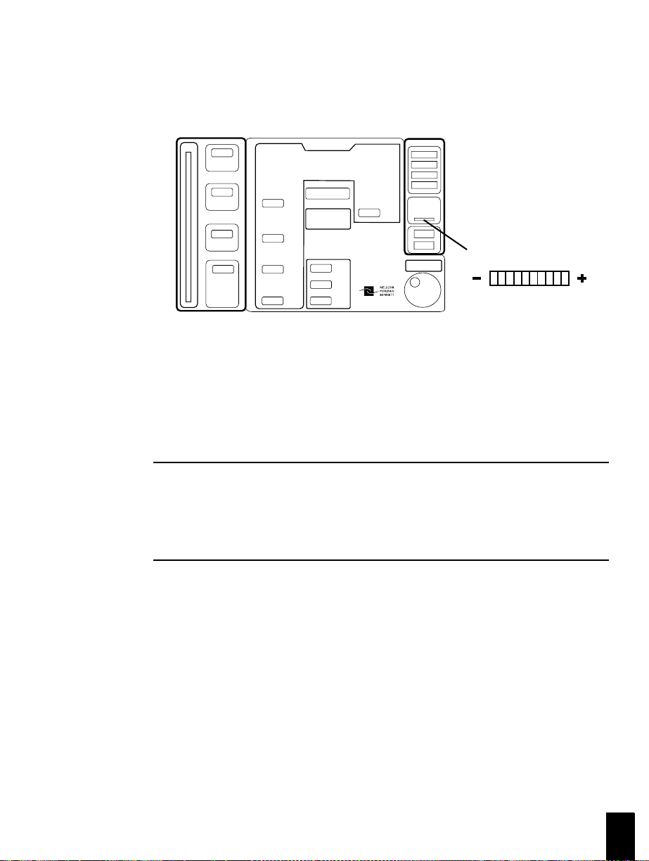
Every 700 Series Ventilator System includes an internal battery as a backup
power supply that comes standard with the ventilator. The internal battery can
provide up to 2
½ hours of backup power, depending on ventilator settings and
battery charge level. The ventilator operates on backup power when ac power is
lost or drops below minimum. The internal battery’s charge level is continuously
700 Series Ventilator Operator’s Manual G-061874-00 Rev. D (09/00)
Page 47
.
Setting up the ventilator 2
-
+
...............................................................................
indicated on the keyboard (see Figure 2-2). The ventilator alarms when it
determines that only 5 minutes of power remain using the current settings.
Internal battery level
7-00054
Figure 2-2. Internal battery charge indicator
The optional external battery supplies up to 7 additional hours of backup power in
case ac power is lost or falls below minimum. (See Appendix B for external
battery ordering information.) If installed, the external battery is the first source
of backup power. The ventilator uses the internal battery if the external battery is
depleted or is not connected.
NOTE:
When the ventilator switches off because battery charge is
inadequate, turn off the power switch to prevent the battery from
being fully depleted. Connect the ventilator to ac power as soon as
possible.
The ventilator charges the internal and external batteries during ac power
operation, or in standby mode when attached to ac power. (See Appendix C for
battery specifications.) When the ventilator is operating on battery, you can use
the MENU key to check the estimated operational time remaining until recharge
is required for the internal and external batteries. (Section 6 tells you how to use
the MENU key.) The ventilator must operate for 2 minutes before it can estimate
battery time remaining.
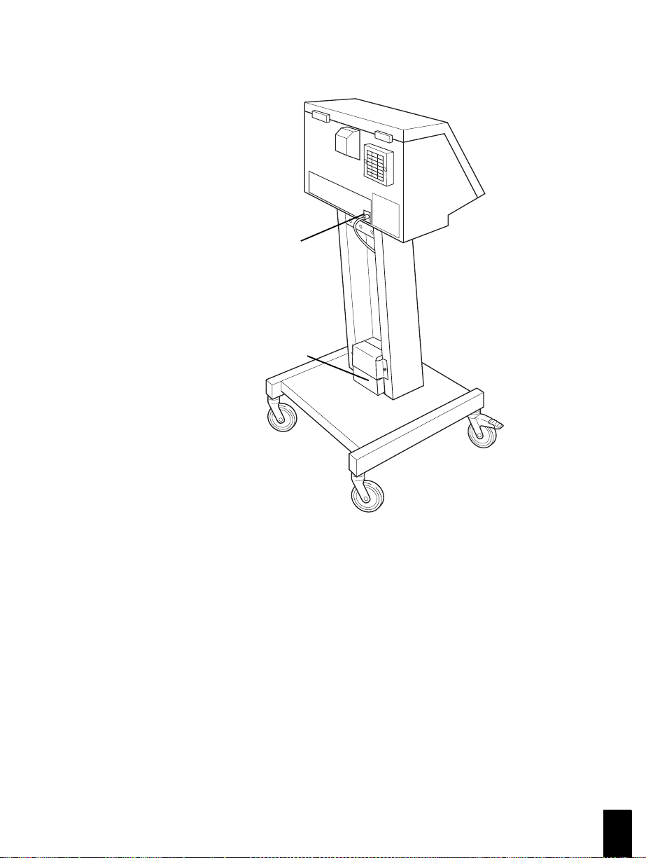
You can disconnect and connect the external battery during normal operation.
When operating the ventilator on battery power, you can install the external
G-061874-00 Rev. D (09/00) 700 Series Ventilator Operator’s Manual
2-3
Page 48

2 Setting up the ventilator
battery on the cart for easy transport. Follow these steps to connect the external
battery:
1. Mount the external battery on the base of the cart (or other suitable
location).
2. Plug the external battery’s cable into the connector (Figure 2-3).
3. Figure 2-4 shows you how to disconnect the external battery.
To ensure that the batteries retain their charge, store the ventilator in standby
mode, with its power switch on, and connected to ac power. If the ventilator is not
stored in this manner, check battery charge levels before using the ventilator.
Caution
If you plan to store the ventilator for more than 6 months, remove
batteries before storage. Replace the internal battery before using
the ventilator again. A qualified service technician must replace the
battery according to the instructions in the 700 Series Ventilator
System Service Manual.
If you turn on the ventilator after it has been unplugged for an extended period,
the LOW EXT BATTERY and LOW INT BATTERY alarms may become active.
If so, recharge the internal battery by leaving the ventilator plugged in and turned
on in standby mode (with no patient connected) for up to 8 hours.
2-4
If the LOW EXT BATTERY, LOW INT BATTERY, or BAT NOT CHARGING
alarm is still active after 8 hours, replace the batteries. If you turn off the
ventilator when the battery is absent or inadequately charged, a LOSS OF
POWER alarm sounds for at least 2 minutes.
NOTE:
The ON BATTERY indicator flashes when the ventilator is operating
on battery power.
700 Series Ventilator Operator’s Manual G-061874-00 Rev. D (09/00)
Page 49
.
Setting up the ventilator 2
...............................................................................
External
battery
connector
External
battery
7-00055
Figure 2-3. Plugging the external battery into the ventilator
G-061874-00 Rev. D (09/00) 700 Series Ventilator Operator’s Manual
2-5
Page 50
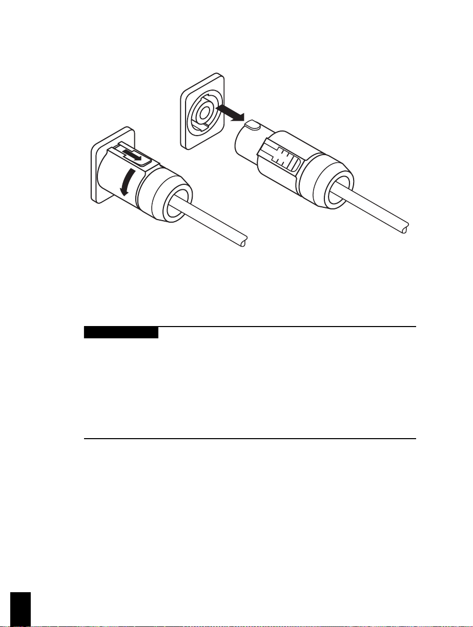
2 Setting up the ventilator
7-00051
Figure 2-4. Disconnecting the external battery
2.2 Connecting the electrical supply
Warning
• To avoid electrical shock hazard, connect the ventilator power
cord into a grounded ac power outlet. If the integrity of the ac
ground is in question, operate the ventilator from the internal or
external battery.
• If used in the U.S., connect the ventilator to an ac receptacle
marked “Hospital Only” or “Hospital Grade” to ensure grounding
reliability.
2-6
Every 700 Series Ventilator System is supplied with a power cord. A power cord
retainer covers the connector and socket to protect against liquid spills or
accidental disconnection.
When the ventilator is ready for operation on ac power, connect the power cord to
ac power (see Figure 2-5).
700 Series Ventilator Operator’s Manual G-061874-00 Rev. D (09/00)
Page 51

.
Setting up the ventilator 2
...............................................................................
NOTE:
During operation on ac power, the power cord retainer must always
be in place.
To ac
power
Power cord retainer
Power cord
Figure 2-5. Connecting the ventilator power cord
When the power cord is not in use, you can wrap the power cord around the
brackets on the back of the ventilator for convenient storage (see Figure 2-6).
Figure 2-6. Storing the power cord on the ventilator
7-00056
7-00057
G-061874-00 Rev. D (09/00) 700 Series Ventilator Operator’s Manual
2-7
Page 52

2 Setting up the ventilator
2.3 Connecting the oxygen supply
Warning
• To ensure proper oxygen concentration, do not obstruct the
ventilator’s air intake.
• To ensure adequate oxygen delivery to the patient, use
Mallinckrodt-supplied oxygen hoses only. Use of other oxygen
hoses could result in inadequate or inappropriate oxygen
pressures or leaks at the oxygen inlet.
• When using a cylinder oxygen supply, point the cylinder's
pressure relief device away from the ventilator air intake. This
helps avoid creating an oxygen-rich environment within the
ventilator in the event that the cylinder oxygen regulator
malfunctions.
The 700 Series Ventilator System can use oxygen from a cylinder or wall supply.
Follow these steps to connect the oxygen supply:
1. Ensure that the oxygen supply pressure is between 40 and 90 psi (275 and
620 kPa) (50 psi (345 kPa) recommended).
2-8
Warning
Due to excessive restriction of certain hose assemblies (listed in
Table B-1), reduced FIO
pressures
levels, make sure that oxygen inlet pressure is ³ 50 psi (345 kPa)
when using these hose assemblies.
2. Connect the oxygen supply to the oxygen inlet connector on the side of the
ventilator (see Figure 2-7). Make sure ventilator is configured with
adapter(s) as required.
Caution
To prevent damage to the ventilator, ensure that the connection to
the oxygen supply is clean and unlubricated.
700 Series Ventilator Operator’s Manual G-061874-00 Rev. D (09/00)
< 50 psi (345 kPa) are used. To maintain correct FIO
levels may result when oxygen inlet
2
2
Page 53

.
Setting up the ventilator 2
...............................................................................
NOTE:
Whenever a pressurized oxygen source is connected to the ventilator,
the oxygen regulator has a maximum bleed rate of 3 L/min, even when
the ventilator is not in use. Always take this bleed rate into account
when calculating oxygen cylinder volume and duration. This is
especially important when using the ventilator and cart while
transporting patients who are being ventilated at above-ambient
levels.
FIO
2
Oxygen inlet
connector
Air intake
Oxygen hose
(to oxygen supply)
7-00058
Figure 2-7. Connecting the oxygen supply
G-061874-00 Rev. D (09/00) 700 Series Ventilator Operator’s Manual
2-9
Page 54

2 Setting up the ventilator
2.4 Connecting the ventilator breathing circuit
Warning
• To minimize the risk of bacterial contamination or component
damage, inspiratory and expiratory filters must always be
handled with care and connected to the ventilator during use.
• Use of an external pneumatically powered nebulizer with a 700
Series Ventilator results in added flow to the ventilator breathing
circuit. This additional flow can affect delivered tidal volumes,
spirometry and spirometry alarms, delivered FIO
triggering. (However, the Mallinckrodt EasyNeb™ Nebulizer is
designed to deliver aerosol medications to the patient without
affecting ventilator performance or patient data.)
• To minimize the risk of patient injury, use only ventilator breathing
circuits qualified for use in oxygen-enriched environments with
700 Series Ventilators. Do not use antistatic or electrically
conductive tubing. To ensure a leak-tight connection, only use
connectors and tubes with ISO-standard cone and socket fittings
(or use adapters to connect barbed cuff fittings to ISO-standard
fittings).
• Use ventilator breathing circuits identified by Mallinckrodt for use
with 700 Series Ventilators or circuits that ensure that the
maximum resistance values specified in Table C-5 are not
exceeded. Using a circuit with a higher resistance does not
prevent the ventilator from ventilating as long as the ventilator
passes SST.
, and patient
2
2-10
Caution
Adding accessories to the ventilator can increase system
resistance. Ensure that any changes to the recommended
ventilator circuit configurations do not exceed the values for
resistance provided in
700 Series Ventilator Operator’s Manual G-061874-00 Rev. D (09/00)
Appendix C.
Page 55

.
Setting up the ventilator 2
...............................................................................
NOTE:
• Mallinckrodt recommends that you run SST every 15 days,
between patients, and when you change the ventilator breathing
circuit. Mallinckrodt recognizes that the protocol for running SST
varies widely among healthcare institutions. It is not possible for
Mallinckrodt to specify or require specific practices that will meet
all needs, or to be responsible for the effectiveness of those
practices.
• Theventilatorusesanoxygensensortotriggeranalarmifthe
delivered % O
setting. You can view the ventilator’s%O2measurement by
using the User settings function of the MENU key.
• Check the inspiratory and expiratory limbs of the ventilator
breathing circuit and the collector vial and in-line water traps
regularly for water buildup. Under certain conditions, they can fill
quickly. In case of a partial occlusion alarm, check for water in the
ventilator breathing circuit. In very severe cases, such a water
occlusion can potentially cause the ventilator to enter occlusion
cycling mode. Empty and clean the collector vial and in-line water
traps as necessary.
• Mallinckrodt recommends using pediatric circuits when
ventilating patients with 5-mm or smaller internal-diameter
artificial airways.
is 10 percentage points above or below the % O
2
2
Figure 2-8 shows how to connect the ventilator breathing circuit, including the
inspiratory filter, humidifier (if used), inspiratory limb, patient wye, expiratory
limb, collector vial, and expiratory filter.
G-061874-00 Rev. D (09/00) 700 Series Ventilator Operator’s Manual
2-11
Page 56

2 Setting up the ventilator
Ventilator
(from patient)
Expiratory filter
(arrow on filter
indicates direction
of flow)
Collector vial
Expiratory
limb of the
ventilator
breathing circuit
Ventilator
(to patient)
Inspiratory filter
(arrow on filter
indicates direction
of flow)
Humidifier
Inspiratory limb of the
ventilator breathing
circuit (install EasyNeb
between inspiratory filter
and patient wye)
Patient wye
7-00059
Ô
2-12
Figure 2-8. Connecting the ventilator breathing circuit
700 Series Ventilator Operator’s Manual G-061874-00 Rev. D (09/00)
Page 57

.
Setting up the ventilator 2
...............................................................................
2.5 Installing the collector vial
Figure 2-9 shows you how to slide the collector vial into the bracket on the cart or
shelf mounting plate.
Bracket
(on cart or
shelf-mounting
plate)
Collector
vial
7-00060
Figure 2-9. Installing the collector vial
G-061874-00 Rev. D (09/00) 700 Series Ventilator Operator’s Manual
2-13
Page 58

2 Setting up the ventilator
2.6 Installing the flex arm
Figure 2-10 shows you how to install the flex arm onto the threaded socket on the
ventilator.
Flex arm
2-14
7-00061
Figure 2-10. Installing the flex arm
NOTE:
If the flex arm is too large to fit into a tight space, you can shorten
the arm by removing the middle segment (Figure 2-11).
700 Series Ventilator Operator’s Manual G-061874-00 Rev. D (09/00)
Page 59

.
Setting up the ventilator 2
...............................................................................
Remove
Remove
Remove
7-00062
Figure 2-11. Shortening the flex arm
G-061874-00 Rev. D (09/00) 700 Series Ventilator Operator’s Manual
2-15
Page 60

2 Setting up the ventilator
2.7 Installing the humidifier
Figure 2-12 shows you how to slide the humidifier into the bracket on the cart or
shelf mounting plate.
NOTE:
The humidifier must be powered independently of the ventilator
(regardless of whether the ventilator is running on ac or battery
power).
Bracket
(on cart or
shelf-mounting
plate)
2-16
Humidifier
7-00063
Figure 2-12. Installing the humidifier
700 Series Ventilator Operator’s Manual G-061874-00 Rev. D (09/00)
Page 61

.
Setting up the ventilator 2
...............................................................................
2.8 Using the ventilator cart
The ventilator cart is equipped with a storage area for the external battery. You
can lock and unlock the cart’s front wheels with your foot, as shown in Figure
2-13.
Caution
To prevent equipment damage, pull, rather than push, the ventilator
over high thresholds when using the cart to transport the ventilator.
Ensure that the flex arm is positioned at the front of the ventilator.
Ventilator
cart base
Unlocked
Locked
Unlocked
7-00064
Figure 2-13. Locking and unlocking the cart’s front wheels
G-061874-00 Rev. D (09/00) 700 Series Ventilator Operator’s Manual
2-17
Page 62

2 Setting up the ventilator
2-18
700 Series Ventilator Operator’s Manual G-061874-00 Rev. D (09/00)
Page 63

SECTION
Getting started 3
3
..............................................................................
This section tells you how to:
• Power up the ventilator
• Select ventilator settings
• View and change alarm limits
• Enter and exit standby mode
NOTE:
Mallinckrodt recommends that before using the ventilator for the
first time, you wipe the ventilator exterior clean and sterilize its
components according to the instructions in Appendix A. Follow
your institution’s protocol for cleaning and sterilizing the ventilator
and its components.
3.1 Powering up the ventilator
NOTE:
To ensure battery charge(s), store the ventilator in standby mode
with the power cord plugged into the mains and the power switch in
the on (I) position whenever possible. The power switch controls ac
mains and battery power to the ventilator.
1. Turn the power switch on (see Figure 3-1). The ventilator displays this
message:
POST running...
NPB 7x0 S/W Rev x
PM due xxxxx hrs
“PM due” refers to the number of hours until a routine preventive
maintenance procedure is due, based on the ventilator’s operational hours.
G-061874-00 Rev. D (09/00) 700 Series Ventilator Operator’s Manual
3-1
Page 64

3 Getting started
Warning
If a single beep is not audible during POST, the main audible
alarm may be malfunctioning. Remove the ventilator from use and
contact service.
NOTE:
• If the ventilator is running on ac but the battery is low, upon
power up it may begin ventilating using the last valid settings and
an ABNORMAL RESTART alarm may occur.
• Do not switch off ventilator power during POST.
3-2
7-00065
Figure 3-1. Turning the power switch on (the “I” position)
2. Once the power-on self-test (POST) is complete (several seconds), the
ventilator displays the message:
Accept settings
to start ventilation
The last valid settings are proposed, and the appropriate indicator lights to
show the ventilator’s source of power.
700 Series Ventilator Operator’s Manual G-061874-00 Rev. D (09/00)
Page 65

.
Getting started 3
...............................................................................
Warning
Always let the ventilator run for 10 minutes before placing it on a
patient to allow heaters to warm up. Failure to warm up the
ventilator could result in failure of the SST flow sensor test, and
higher measured exhaled tidal volumes.
Caution
Mallinckrodt recommends running short self-test (SST) and testing alarms to
check proper operation of the ventilator before ventilation begins or according
to your institution’s protocol. Section 4 tells you how to run SST. Appendix E
tells you how to test alarms.
NOTE:
If the ventilator detects low oxygen pressure, a low battery level, or an
occluded or missing air intake filter during POST, POST continues
uninterrupted. These alarms become active when POST is complete, and you
can override them by pressing the alarm reset key.
G-061874-00 Rev. D (09/00) 700 Series Ventilator Operator’s Manual
3-3
Page 66

3 Getting started
3.2 Selecting ventilator settings
NOTE:
Each keypress should result in a “blip” sound; otherwise, the main
alarm speaker may be faulty. If a keypress does not result in this
sound, turn the ventilator off then on to run POST and verify the
proper functioning of the speaker.
1. Select the mode: To select a mode, press A/C, SIMV, or SPONT.
(Appendix D gives a detailed explanation of these ventilation modes.)
In assist/control (A/C) mode, you can only select volume
A/C
SIMV
SPONT
control ventilation (VCV) or pressure control ventilation
(PCV) settings (PCV is only available on the 760
Ventilator).
In synchronous intermittent mandatory ventilation (SIMV)
mode, you can select both VCV or PCV (760 only) and
pressure support ventilation (PSV) settings.
In spontaneous (SPONT) mode, you can only select PSV
settings.
3-4
2. Confirm or change settings: For every flashing key light, you must touch
the key (and adjust the setting if necessary) before you can apply the
settings. You can confirm or change settings in any order.
Once you press a key, the proposed
setting flashes to indicate that the knob
is linked to the selected setting. The
setting’s LCD window shows the
setting and the message window
displays the current setting, range,
units, name of the setting, and
associated parameter. Turn the knob to
change the setting or press another key
Press each flashing key and
turn the knob to adjust.
7-00066
to leave the setting as is. (The setting
then stops flashing.)
700 Series Ventilator Operator’s Manual G-061874-00 Rev. D (09/00)
Page 67

.
Getting started 3
...............................................................................
3. Press CLEAR to cancel the most recently changed setting and return to the
last valid setting. (This only works if you haven’t pressed ACCEPT yet.)
Pressing CLEAR after you’ve pressed 100% O
maneuver. The ventilator will beep if you attempt to change a setting to a
value above or below the setting range.
stops the 100% O
2
2
4. PEEP/CPAP, TRIGGER SENSITIVITY, and % O
: You can
2
change these settings in any mode. These keys don’t flash
when you select a new mode, and you are not required to
confirm these settings.
NOTE:
The O
% alarm is delayed for 30 seconds and 12 L of tidal volume
2
following a change in setting so that the oxygen concentration
can stabilize.
5. Apply the settings: Press ACCEPT.
ACCEPT
NOTE:
If apnea ventilation is possible, the ventilator displays this message
when normal ventilation begins:
PEEP/CPAP
TRIGGER
SENSITIVITY
L/min
%O2
7-00067
Review Ta = xx s
where Ta is the apnea interval and xx is the current setting in
seconds (from 10 to 60 s). Section 5 tells you how to adjust apnea
ventilation parameters. You are not required to review apnea
parameters before normal ventilation begins.
G-061874-00 Rev. D (09/00) 700 Series Ventilator Operator’s Manual
3-5
Page 68

3 Getting started
Ventilation begins according to the displayed settings and the existing alarm
limits. You should review all alarm limits and change them if necessary.
(Section 3.3 tells you how.) You can change alarm limits or ventilator
settings at any time during normal ventilation.
Warning
In PSV it is impossible to set support pressure + PEEP to
deliberately cause a HIGH PRESSURE alarm. Although
Mallinckrodt does not recommend doing so, it is possible in VCV to
set a tidal volume that causes breath truncation and a HIGH
PRESSURE alarm. To avoid activating a HIGH PRESSURE alarm,
select the appropriate TIDAL VOLUME and HIGH PRESSURE
alarm settings.
3.3 Viewing and changing alarm settings
You can view alarm settings at any time without affecting ventilation by pressing
the appropriate key. The ALARM SETTINGS window displays the value of the
alarm being viewed or changed. The alarm setting flashes for up to 30 seconds,
and you can change an alarm setting any time its setting is flashing in the window.
3-6
All alarm settings are in effect during ventilation (except for LOW INSP
PRESSURE, which is not active in SPONT mode). You can change alarm
settings at any time during ventilation. You can only change one alarm setting at
a time.
700 Series Ventilator Operator’s Manual G-061874-00 Rev. D (09/00)
Page 69

.
Getting started 3
...............................................................................
To change a setting: touch, turn, ACCEPT.
1. Touch the key: The key light turns on, and
the current alarm setting flashes in the
window for 30 seconds. The message
window shows the current setting, range,
and units of the alarm.
2. Turn the knob to adjust the alarm setting
(this only works when the alarm setting is
flashing in the window). The ventilator will
beep if you attempt to select a setting
above or below the setting range.
3. Press ACCEPT to apply the new alarm
setting. The new alarm setting stops
flashing and the message window displays
this message:
Setting(s) accepted
Warning
• Inadvertent extubation in which the endotracheal tube remains
connected to the breathing circuit could result in pressurization
above the LOW INSP PRESSURE alarm setting. The LOW INSP
PRESSURE and low volume alarms should be set appropriately.
• To ensure patient safety, always set the LOW TIDAL VOLUME
and HIGH RATE alarms.
ACCEPT
7-00066
7-00068
7-00067
G-061874-00 Rev. D (09/00) 700 Series Ventilator Operator’s Manual
3-7
Page 70

3 Getting started
NOTE:
The O
alarm limit is 10 percentage points above the set % O
O
measured % O
enabled (using the Oxygen sensor menu function, described in
Section 6).
3.4 Entering and exiting standby mode
Standby mode is a waiting state in which there is no ventilation, but the ventilator
maintains its settings and battery charge(s).
Warning
• To avoid raising the oxygen concentration of room air, ensure that
• To avoid patient injury due to lack of ventilatory support, do not
% alarm limits are based on the set % O2. The high O2%
2
% alarm limit is 10 percentage points below the set % O2.The
2
isshowninthemessagewindowifitsdisplayis
2
, and the low
2
the ventilator is in an adequately ventilated room if connected to
an oxygen supply while in standby mode. Disconnect the oxygen
supply if you do not intend to use the ventilator immediately.
enter standby mode with a patient attached to the ventilator. You
must confirm that no patient is attached before entering standby
mode.
3-8
NOTE:
To maintain battery charge(s), the ventilator must be plugged into
ac power with the power switch on while in standby mode.
Follow these steps to enter standby mode:
1. Turn on the ventilator. If ventilation has already begun, you must turn off
the ventilator, then turn it back on without starting ventilation. This allows
you access to the Standby mode menu function.
2. Press MENU.
3. Turn the knob to select standby mode.
700 Series Ventilator Operator’s Manual G-061874-00 Rev. D (09/00)
Page 71

.
Getting started 3
...............................................................................
4. Press ACCEPT. The ventilator displays this message:
Is pt disconnected?
ACCEPT to proceed
5. Confirm that no patient is attached by pressing ACCEPT. (If you don’t press
ACCEPT while this message is displayed, the ventilator will not enter
standby mode.)
6. This message tells you that the ventilator is in standby mode:
In standby mode
Clear to exit
The ON AC/BATTERY CHARGING, INTERNAL BATTERY LEVEL,
and SAFETY VALVE OPEN indicators turn on. All other key lights and
displays are off during standby mode. The only alarms that can become
active during standby mode are FAN FAILED ALERT, BAT NOT
CHARGING, LOSS AC POWER, and LOSS OF POWER.
Follow these steps to exit from standby mode and resume ventilation:
1. Press CLEAR.
2. The ventilator displays this message:
POST running...
3. After a few seconds, POST is complete and the ventilator begins ventilation
using the last valid settings.
G-061874-00 Rev. D (09/00) 700 Series Ventilator Operator’s Manual
3-9
Page 72

3 Getting started
3-10
700 Series Ventilator Operator’s Manual G-061874-00 Rev. D (09/00)
Page 73

SECTION
Self tests (SST and EST) 4
4
..............................................................................
All 700 Series Ventilators include these built-in self tests:
• Short self test (SST) is a short (about 2 to 3 minutes) and simple sequence of
tests that verifies proper ventilator operation, checks the ventilator breathing
circuit for leaks, and measures the circuit compliance. Power on self test
(POST) is part of SST.
• Extended self test (EST) is a thorough test of the operational integrity of the
ventilator, both the electronics and the pneumatics. POST and SST are part of
EST.
Warning
• Before running SST or EST, you must disconnect the ventilator
from the patient. Running SST or EST while the ventilator is
connected to the patient can injure the patient.
• A fault identified in SST or EST indicates that the ventilator or an
associated component is defective. A defective ventilator or
associated component should be repaired before the ventilator is
returned to service, unless it can be determined with certainty
that the defect cannot create a hazard for the patient, or add to
the risks which may arise from other hazards.
Caution
To ensure accurate SST and EST operation, run SST and EST in
room air (% O
at least 10 minutes. (EST also requires an oxygen supply.)
Table 4-1 describes SST and EST.
G-061874-00 Rev. D (09/00) 700 Series Ventilator Operator’s Manual
is 21%) after the ventilator has been powered on for
2
4-1
Page 74

4 Self tests (SST and EST)
Tabl e 4-1: 700 Series Ventilator self tests
Test
name
Short self
test (SST)
Extended
self test
(EST)
Purpose When test is run
An abbreviated version of EST to be run
primarily by the operator. Makes detailed
checks of the pneumatics and electronics. It
also characterizes system leaks and system/
tubing compliance to compensate during
breath delivery. POST is run as part of SST.
Thoroughly tests the operational integrity of
the ventilator, both the electronics and
pneumatics. POST and SST are part of EST.
Before patient is connected
to the ventilator or after
ventilator breathing circuit or
humidifier is changed.
• When the ventilator
is serviced.
• As part of the ventilator
performance verification.
• Following a ventilator
inoperative.
NOTE:
The performance verification, described in the 700 Series Ventilator
System Service Manual, is a more thorough test of the ventilator to
verify specifications are met. The technician runs a partial or full
performance verification after servicing the ventilator and at regular
intervals.
4-2
700 Series Ventilator Operator’s Manual G-061874-00 Rev. D (09/00)
Page 75

.
Self tests (SST and EST) 4
...............................................................................
4.1 Short self test (SST)
Table 4-2 summarizes the functions of SST.
NOTE:
• Mallinckrodt recommends that you run SST every 15 days,
between patients, and when you change the ventilator breathing
circuit. Mallinckrodt recognizes that the protocol for running SST
varies widely among healthcare institutions. It is not possible for
Mallinckrodt to specify or require specific practices that will meet
all needs, or to be responsible for the effectiveness of those
practices.
• When SST asks you to do something (for example, press
ACCEPT or block the patient wye), the ventilator will wait
indefinitely for your response.
Follow these steps to run SST:
1. Turn on the ventilator. If ventilation has already begun, you must turn off
the ventilator, then turn it back on without starting ventilation. This allows
you access to the Self test menu function.
If you select the Self test function during ventilation the window displays
this message:
N/A in ventilation
2. Press MENU, turn the knob to select Self test, then press ACCEPT. The
usual 30-second timeout for your input is disabled during the entry to the
Self test function.
3. The window displays this message:
Shortselftest
Turn knob to view
4. Turn the knob to select Short self test (you can also select Extended self
test). The window displays this message:
Shortselftest
Vent warming 09:59
CLEAR to bypass
G-061874-00 Rev. D (09/00) 700 Series Ventilator Operator’s Manual
4-3
Page 76

4 Self tests (SST and EST)
If the ventilator has already been running for more than 10 minutes before
you select Short self test, this message is bypassed (see step 5). If the
ventilator was recently running and is already warmed up, you can press
CLEAR to override the Ve nt w ar min g message and begin SST. Mallinckrodt
cannot guarantee the accuracy of test results in this case, however.
5. The window displays this message:
Is pt disconnected?
ACCEPT to proceed
6. Press ACCEPT to confirm that no patient is connected to the ventilator. (Or
press CLEAR to back up through the menu.) The window displays this
message:
Block wye
7. Block the patient wye and then press ACCEPT.
8. The ventilator runs power-on self-test (POST) and displays this message for
a few seconds:
POST running...
Warning
If a single beep is not audible during POST, the main audible alarm
may be malfunctioning. Remove the ventilator from use and contact
service.
4-4
NOTE:
• If the ventilator is running on ac but the battery is low, upon
power up it may begin ventilating using the last valid settings and
an ABNORMAL RESTART alarm may occur.
• During POST it is recommended that you not switch off
ventilator power.
9. The message window then displays this message:
humidification device type
Choose humidifier
700 Series Ventilator Operator’s Manual G-061874-00 Rev. D (09/00)
Page 77

.
Self tests (SST and EST) 4
...............................................................................
where the humidification device type is the most recently selected type, as
follows:
• HME: Heat moisture exchanger (“artificial nose”)
• Dual heated wire: Humidifier with heated wire on expiratory limb, or on
both inspiratory and expiratory limbs
• No heated wire: Conventional humidifier without heated wire circuit on
the expiratory limb
Turn the knob to select the humidifier type attached, then press ACCEPT.
Warning
Incorrectly specifying the humidifier type during SST can affect the
accuracy of spirometry calculations.
10. The message window then displays this message:
tubing type
Choose tubing type
where the tubing type is the most recently selected ventilator breathing
circuit type.
Turn the knob to select the ventilator breathing circuit type (adult or
pediatric tubing) attached to the ventilator, then press ACCEPT.
Warning
Incorrectly specifying the ventilator breathing circuit type during
SST can cause an inappropriate sensitivity for the leak test and
occlusion alarm. Mallinckrodt recommends using pediatric circuits
when ventilating patients with 5-mm or smaller internal-diameter
artificial airways.
NOTE:
To ensure that compliance compensation functions correctly, you
must run SST with the circuit configured as intended for use on
the patient.
G-061874-00 Rev. D (09/00) 700 Series Ventilator Operator’s Manual
4-5
Page 78

4 Self tests (SST and EST)
11. The message window then displays this message:
ET size: x.x mm
Choose ET size
Turn the knob to select the appropriate ET (endotracheal tube) size, then
press ACCEPT.
Warning
Specifying an ET tube size that is too large can cause premature
termination of breaths on very small pediatric patients. During
normal ventilation, you can use the MENU key’s User settings
function to change the ET tube size (see Section 6).
12. The ventilator automatically starts the test sequence. A message indicates
which test is being performed. Once started, a test cannot be interrupted. In
most cases you don’t need to do anything unless a test result is fault or fail,
or your action is required. When a test passes, SST automatically starts the
next test.
NOTE:
The PRESSURE bar graph and the PRESSURE display window
show the real-time expiratory pressure throughout SST.
4-6
700 Series Ventilator Operator’s Manual G-061874-00 Rev. D (09/00)
Page 79

.
Self tests (SST and EST) 4
...............................................................................
These keys are valid during SST:
To confirm that a requested action is complete.
ACCEPT
To repeat a test, return to the prompt at the start of a test, or indicate an
CLEAR
inaudible alarm (during the Main alarm speaker test and Backup alarm
test only).
MANUAL
INSP
7-00424
7-00423
7-00072
To override an Incomplete or Fault test result.
To restart from the beginning of SST.
TostoptestingandskiptotheendofSST.
NOTE:
If the tubing or humidifier type or ET tube size that you’ve selected has
changed from the previous time SST was run, this key is temporarily
disabled until the Circuit comp test is complete.
G-061874-00 Rev. D (09/00) 700 Series Ventilator Operator’s Manual
4-7
Page 80

4 Self tests (SST and EST)
13. The I/E filter test prompts you to complete these actions (press ACCEPT
when each action is complete):
Display:
Disconnect I tubing
Reconnect I tubing
Display:
Unblock wye
Block wye
Display:
Disconnect E tubing
Reconnect E tubing
(Do not disconnect inspiratory filter.)
+
-
740 Ventilator
7-00069
+
-
740 Ventilator
7-00070
(Do not disconnect expiratory filter.)
+
-
4-8
740 Ventilator
7-00071
700 Series Ventilator Operator’s Manual G-061874-00 Rev. D (09/00)
Page 81

.
Self tests (SST and EST) 4
...............................................................................
14. When the final test in the sequence is complete, this message is displayed
along with the overall SST result:
SST finished testing
Table 4-3 summarizes overall SST results and how to proceed in each case.
15. Unblock the patient wye, then press ACCEPT. The ventilator reruns POST.
Table 4-2: SST sequence of tests
Test Function Comments
Is pt
disconnected?
Leak test Checks the ventilator breathing
P
ePcyl
compare
Auto-zero sol
test
Circuit comp
test
Safety valve
test
Asks for confirmation that a
patient is not connected to
the ventilator.
circuit for leaks. Displays
expiratory pressure on
pressure bar graph.
Verifies proper function of
pressure transducers in
internal pneumatics and
ventilator breathing circuit.
Displays expiratory pressure
on pressure bar graph.
Verifies the proper function
(ability to open and close) of
(expiratory) and P
the P
e
(cylinder) solenoids.
Determines the compliance of
the ventilator breathing circuit.
Displays expiratory pressure
on pressure bar graph.
Verifies that safety valve
relieves excess circuit
pressure. Displays expiratory
pressure on pressure bar
graph.
cyl
SST cannot proceed until you confirm
that a patient is not connected.
Fault if not passed.
Overriding a fault could cause
improper compliance compensation,
inaccurate tidal volume delivery,
or autocycling.
Fault if not passed.
Overriding a fault could cause
improper compliance compensation,
or autocycling.
Failu re if not passed.
Fault if not passed.
Overriding a fault could cause
improper compliance compensation or
inaccurate tidal volume delivery.
Failu re if not passed.
G-061874-00 Rev. D (09/00) 700 Series Ventilator Operator’s Manual
4-9
Page 82

4 Self tests (SST and EST)
Table 4-2: SST sequence of tests (continued)
Test Function Comments
PEEP system
test
Flow/O
2
sensor test
I/E filter test Checks the pressure drop
Heaters test Verifies correct operation of
Verifies that the PEEP system
can generate and maintain
preset PEEP levels. Displays
expiratory pressure on
pressure bar graph.
Checks the accuracy of the
exhalation flow sensor and the
oxygen sensor.
across the inspiratory and
expiratory limbs of the entire
patient system. Checks the
pressure drop across the filters.
the heaters in the exhalation
subsystem.
Failu re if not passed.
Failu re if flow sensor test does not
pass.
Fault if oxygen sensor test does not
pass. Use the MENU key’sOxygen
sensor function to recalibrate the
oxygen sensor (see Section 6).
Overriding a fault (oxygen sensor test
only) could result in inaccurate % O
measurement.
Fault if not passed. This test is
optional: pressing CLEAR at the initial
prompt skips this test.
Skipping this test or overriding a fault
could result in inadequate bacteria
protection or excessive resistance to
inspiration or exhalation.
Fault if not passed.
Overriding a fault could cause
inaccurate monitoring of exhaled
volume or lead to damage to the
ventilator’s flow sensor or exhalation
valve.
2
4-10
Main alarm
test
700 Series Ventilator Operator’s Manual G-061874-00 Rev. D (09/00)
Sounds alarm at three volumes
and verifies that user reports
hearing it.
Failu re if not passed.
If alarm is audible press ACCEPT. If
not, press CLEAR.
Page 83

.
Self tests (SST and EST) 4
...............................................................................
Table 4-2: SST sequence of tests (continued)
Test Function Comments
Backup alarm
test
Checks the operation of the
backup alarm circuit.
NOTE:
Faults detected during SST may require removing the ventilator
from clinical use immediately and servicing it. A trained operator,
however, must evaluate the situation and determine whether the
ventilator can be used. Failures detected during SST require
rerunning SST (using the alarm reset key). It is not possible to exit
SST if SST fails. If SST continues to fail, the ventilator must be
removed from service
Fault if not passed. If alarm is audible
pressACCEPT.Ifnot,pressCLEAR.
Overriding a fault could cause no
backupaudiblealarmincasethemain
audible alarm fails.
G-061874-00 Rev. D (09/00) 700 Series Ventilator Operator’s Manual
4-11
Page 84

4 Self tests (SST and EST)
Table 4-3: Overall SST results
If the SST
result is:
SST passed All tests passed. Press ACCEPT to exit SST or press
SST
incomplete
SST fault One or more tests did not pass.
SST failed One or more critical problems
*If you press MANUAL INSP to exit SST, you will be prompted to confirm that you wish to override the fault or incomplete test.
Confirm by pressing MANUAL INSP again.
All tests performed were passed,
but some were skipped. The
skipped tests were passed on a
previous run.
These tests might not
compromise the ventilator’s ability
to ventilate safely, based on the
operator’s evaluation of the
situation.
were detected.
It means: Do this:
the alarm reset key to restart SST
from the beginning.
Press the alarm reset key to restart
SST from the beginning or press
MANUAL INSP to override this
result and exit SST.*
Press the alarm reset key to restart
SST from the beginning or press
MANUAL INSP to override this
result and exit SST.*
Press the alarm reset key to rerun
SST. It is not possible to exit SST if
SST fails. If SST continues to fail,
remove the ventilator from use and
contact service.
4-12
700 Series Ventilator Operator’s Manual G-061874-00 Rev. D (09/00)
Page 85

.
Self tests (SST and EST) 4
...............................................................................
4.2 Extended self test (EST)
To run EST, you must have the hardware listed in Table 4-4.
Table 4-4: EST hardware requirements
Hardware description
Ventilator breathing
circuit
Stopper, wye (no. 2) G-061574-00 or local supplier
Stopper, inspiration
port (no. 3)
Oxygen source, 40 to
90 psi (275 to 620 kPa)
Warning
Due to excessive restriction of Air Liquide, Australian, and Dräger hose assemblies,
reduced FIO
Make sure oxygen inlet pressure is ³ 50 psi (345 kPa) when using these hose
assemblies, to maintain correct FIO
levels can result if you use oxygen inlet pressures < 50 psi (345 kPa).
2
To use as test circuit: G-061208-00 or equivalent (adult,
reusable, without heated wire)
NOTE:
To ensure that compliance compensation functions
correctly, the user must run EST or SST with the circuit
configured as intended for use on the patient.
G-061575-00 or local supplier
Local supplier
Manufacturer/model or Mallinckrodt
part number
levels.
2
NOTE:
Mallinckrodt recommends that you always run the full EST before
placing the ventilator into operation following service and as part of
the ventilator’s routine performance verification. For more
information on performance verification, see the 700 Series
Ventilator System Service Manual.
G-061874-00 Rev. D (09/00) 700 Series Ventilator Operator’s Manual
4-13
Page 86

4 Self tests (SST and EST)
Follow these steps to run EST:
1. Set up the ventilator as for normal operation, complete with humidifier, if
applicable, and leak-tight ventilator breathing circuit.
2. Turn on the ventilator. If ventilation has already begun, you must turn off the
ventilator, then turn it back on without starting ventilation. This allows you
access to the Self test menu function.
3. Press MENU, turn the knob to select Self test,thenpressACCEPT.
4. Turn the knob to select Extended self test. The window displays the
messages shown in Table 4-5.
Table 4-5: EST setup messages
Message Description
Extended self test
Vent war mi ng xx:xx
CLEAR to bypass
Is pt disconnected? Confirm that patient is disconnected by pressing ACCEPT; or press
Block wye Install no. 2 stopper and then press ACCEPT.
POST running... Wait a few seconds until POST is completed.
This message is displayed (followed by a countdown) if you just
turned on the ventilator. The ventilator must be on for 10 minutes
before running EST so that component temperatures can stabilize.
If the ventilator was recently running and is already warmed up, you
can press CLEAR to override the Vent warming message and begin
SST. Mallinckrodt cannot guarantee the accuracy of test results in
this case, however.
CLEARtoreturntoservicemenu.
NOTE:
• If a single beep is not audible during POST, the main audible
alarm may be malfunctioning. Contact service.
• During POST do not switch off ventilator power.
4-14
700 Series Ventilator Operator’s Manual G-061874-00 Rev. D (09/00)
Page 87

.
Self tests (SST and EST) 4
...............................................................................
Table 4-5: EST setup messages (continued)
Message Description
humidification
device type
Choose humidifier
tubing type
Choose tubing type
Turn knob to select desired humidification device, then press
ACCEPT. Device types include: HME (heat-moisture exchanger or
“artificial nose”), Dual heated wire (humidifier with heated wires on
both inspiratory and expiratory limbs), or No heated wire (humidifier
without a heated wire on expiratory limb).
Warning
Incorrectly specifying the humidifier type during EST can affect
the accuracy of spirometry calculations.
Turn knob to select either Adult tubing or Pediatric tubing and then
press ACCEPT.
Warning
Incorrectly specifying the ventilator breathing circuit type
during EST can cause an inappropriate sensitivity for the leak
test and occlusion alarm. Mallinckrodt recommends using
pediatric circuits when ventilating patients with 5-mm or
smaller internal-diameter artificial airways.
NOTE:
To ensure that compliance compensation functions correctly, run
EST with the circuit configured as intended for use on the patient.
ET size: x.x mm
Choose ET size
Turn knob to select appropriate ET (endotracheal tube) size, and
then press ACCEPT.
Warning
Specifying an ET tube size that is too large can cause premature
termination of breaths on very small pediatric patients. During
normal ventilation, you can use the MENU key’s User settings
function to change the ET tube size (see Section 6).
G-061874-00 Rev. D (09/00) 700 Series Ventilator Operator’s Manual
4-15
Page 88

4 Self tests (SST and EST)
5. The ventilator automatically starts the test sequence (Table 4-6). Unless a
test requires your intervention (and waits indefinitely for your response),
you don’t need to do anything until a test result is fault or failed, or EST is
complete. Use the keys listed in Table 4-7 as needed.
Table 4-6: EST test sequence
Test number
and name
1. DAC-ADC
loop test
2. Safety
valve test
3. Motor
sensor test
4. Zeroing of
Po
5. O
2
solenoids
test
Function Comments
A loopback test to check
digital-to-analog (D/A) and
analog-to-digital (A/D)
converters’ operation.
Verifies that safety valve relieves
excess circuit pressure.
Checks operation of rotary
encoder.
Zeroes oxygen regulator
pressure transducer.
Disconnect and reconnect
oxygen supply, as directed.
Press ACCEPT to signify you
have performed each requested
action.
Checks oxygen solenoids and
oxygen sensor.
Failure if not passed. Not in SST.
Failure if not passed. Also in SST.
Failure if not passed. Not in SST.
Faultifnotpassed.NotinSST.
NOTE:
Overriding this fault could
result in inaccurate oxygen
percentage delivery.
Faultifnotpassed.NotinSST.
NOTE:
Overriding this fault could
result in inaccurate oxygen
percentage delivery.
4-16
6. Flow
sensor test
700 Series Ventilator Operator’s Manual G-061874-00 Rev. D (09/00)
Checks accuracy of exhalation
flow sensor.
Failure if not passed. Also in SST.
Page 89

.
Self tests (SST and EST) 4
...............................................................................
Table 4-6: EST test sequence (continued)
Test number
and name
7. Leak test Checks ventilator breathing
circuit for leaks.
7. PeP
cyl
compare
(also part
of test 7)
7. Auto-zero
sol test
(also part
of test 7)
Verifies proper functioning of
pressure transducers and
ventilator breathing circuit.
Verifies the proper function of the
and P
P
e
Function Comments
solenoids.
cyl
Faultifnotpassed.AlsoinSST.
NOTE:
Overriding this fault could
cause improper compliance
compensation, inaccurate
tidal volume delivery, or
autocycling.
Faultifnotpassed.AlsoinSST.
NOTE:
Overriding this fault could
cause improper compliance
compensation, inaccurate
tidal volume delivery, or
autocycling.
Failure if not passed. Also in SST.
NOTE:
Overriding this fault could
cause improper compliance
compensation, inaccurate
tidal volume delivery, or
autocycling.
8. Circuit
comp test
G-061874-00 Rev. D (09/00) 700 Series Ventilator Operator’s Manual
Determines ventilator breathing
circuit compliance.
Faultifnotpassed.AlsoinSST.
4-17
Page 90

4 Self tests (SST and EST)
Table 4-6: EST test sequence (continued)
Test number
and name
9. I/E filter test Checks pressure drop across
inspiratory and expiratory limbs
of entire patient system. Checks
pressure drop across filters.
Disconnect and reconnect
inspiration (I) tube from/to
inspiratory filter outlet, and
exhalation (E) tube from/to
expiratory filter inlet, as directed.
Block and unblock wye with a no.
2 stopper, as directed. Press
ACCEPT to signify you have
performed each requested
action.
10. PEEP
system
test
Verifies that PEEP system can
generate and maintain preset
PEEP levels within either of two
sets of limits. If results are within
the inner set of limits, test passes
the first time. If the results are
outside of the outer set of limits,
test fails the first time. If the
results are outside the inner
limits but within the outer limits,
the ventilator adjusts its
calibration table in nonvolatile
RAM (NVRAM) and repeats the
test to verify the calibration. The
test fails if the calibration cannot
be verified after five attempts.
Function Comments
Faultifnotpassed.AlsoinSST.
Mandatory in EST, but optional in
SST.
NOTE:
Overriding this fault could
result in inadequate bacteria
protection or excessive
resistance to inspiration or
exhalation.
Failure if not passed. Also in SST, but
not identical.
4-18
11. Check
valve test
700 Series Ventilator Operator’s Manual G-061874-00 Rev. D (09/00)
Checks check valves on inlet and
outlet por ts of cylinder and on
exhalation limb of ventilator
breathing circuit.
Failure if not passed. Not in SST.
Page 91

.
Self tests (SST and EST) 4
...............................................................................
Table 4-6: EST test sequence (continued)
Test number
and name
12. Piston
leak test
13. Lightsdisplays
test
14. Keys test Verifies that every row and
Checks piston leak against a
table of leak values stored
in NVRAM.
First remove inspiratory filter;
then block and unblock
inspiratory filter port as directed,
using no. 3 stopper. Press
ACCEPT to signify you have
performed each requested
action. Replace inspiratory
tubing at end of test.
Verifies that lights and displays
function.
Observe each named display,
and press ACCEPT to verify that
it is lit. Press CLEAR if a display
is not lit.
column of key matrix can be
correctly read.
Press each named key (each
key’s LED will also be lit). Press
CLEAR if a key’s LED is not lit.
Function Comments
Failure if not passed. Not in SST.
Failure if not passed. Not in SST.
Failure if not passed. Not in SST.
15. Main
alarm test
G-061874-00 Rev. D (09/00) 700 Series Ventilator Operator’s Manual
Checks whether various alarm
sounds are audible (at maximum
volume).
Listen for each named sound,
then press ACCEPT to verify that
it is audible. Press CLEAR if a
sound is not audible.
Failure if not passed. Also in SST.
4-19
Page 92

4 Self tests (SST and EST)
Table 4-6: EST test sequence (continued)
Test number
and name
16. Backup
alarm test
17. Fan test Verifies that main fan is operating
18. Heaters
test
Checks operation of backup
alarm circuit.
Press ACCEPT if alarm is
audible or press CLEAR if alarm
is not audible.
correctly by reading fan status
bits.
Verifies correct operation of
heaters in exhalation system.
Function Comments
Faultifnotpassed.AlsoinSST.
NOTE:
Overriding this fault could result in
no audible alarm if the main
speaker fails.
Failure if not passed. Not in SST.
Faultifnotpassed.AlsoinSST.
NOTE:
Overriding this fault could result in
inaccurate monitoring of exhaled
volume or damage to
the ventilator’sflowsensoror
exhalation valve.
4-20
At the end of each test, the test name and pass/fail/fault status are displayed.
When a test passes, EST automatically starts the next test. You do not need
to do anything unless a test result is Fault or Fa il, or your action is required.
If a test does not pass, you can still continue EST, although the overall EST
result is not passed until the error condition is corrected. Since information
on multiple errors can help troubleshooting, it can be useful to complete
EST even with errors.
700 Series Ventilator Operator’s Manual G-061874-00 Rev. D (09/00)
Page 93

.
Self tests (SST and EST) 4
...............................................................................
Table 4-7: Key functions during EST
Key Function
To confirm that a requested action is complete.
ACCEPT
Repeat a test or return to prompt at start of a test.
CLEAR
MANUAL
INSP
7-00424
7-00423
7-00072
To override an Incomplete or Fault test result.
To restart from the beginning of SST.
To stop testing and skip to the end of SST.
NOTE:
IfthetubingorhumidifiertypeorETtubesizethatyou’ve selected has
changed from the previous time SST was run, this key is temporarily
disabled until the Circuit comp test is complete.
G-061874-00 Rev. D (09/00) 700 Series Ventilator Operator’s Manual
4-21
Page 94

4 Self tests (SST and EST)
6. Some tests display additional prompts, some of which require your
response. These are listed in Table 4-8.
Table 4-8: Prompts during EST
Prompt Your response
Disconnect O2 supply Disconnect ventilator from oxygen supply. Press ACCEPT.
Reconnect O2 supply Reconnect ventilator to oxygen supply. Press ACCEPT.
Disconnect I tubing Disconnect tubing from inspiratory filter outlet. Leave inspiratory
filter in place. Press ACCEPT.
Idrop=xx.xat 100
or
Idrop=xx.xat 40
Reconnect I tubing
Unblock wye Remove stopper from patient wye. Press ACCEPT.
Block wye Insert a stopper into patient wye. Press ACCEPT.
Disconnect E tubing Reconnect tubing to inspiratory filter outlet, and disconnect tubing
Edrop=x.x at 100
or
Edrop=xx.xat 40
Reconnect E tubing
Block insp filt port Remove inspiratory filter. Insert no. 3 stopper into inspiratory filter
Reconnect I tubing Remove stopper from inspiratory filter outlet. Reinstall inspiratory
Name of a section of
display
Upper MDW = blocks? Press ACCEPT to confirm that all pixels are turned on in upper
This is the inspiratory filter pressure drop in cmH
100 L/min (adult tubing) or 40 L/min (pediatric tubing). Reconnect
tubing to inspiratory filter outlet. Press ACCEPT.
from expiratory filter inlet. Leave expiratory filter in place. Press
ACCEPT.
This is the expiratory filter pressure drop in cmH2Oataflowof100
L/min (adult tubing) or 40 L/min (pediatric tubing). Press ACCEPT.
Reconnect tubing to expiratory filter outlet.
outlet. Press ACCEPT.
filter. Press ACCEPT.
Press ACCEPT to confirm that all LEDs/LCDs in named section
are on.
half.
Oataflowof
2
Lower MDW = blocks? Press ACCEPT to confirm that all pixels are turned on in lower
half.
Name of a key Press named key.
4-22
700 Series Ventilator Operator’s Manual G-061874-00 Rev. D (09/00)
Page 95

.
Self tests (SST and EST) 4
...............................................................................
Table 4-8: Prompts during EST (continued)
Prompt Your response
High alarm sound Confirm that you hear alarm by pressing ACCEPT.
Medium alarm sound Confirm that you hear alarm by pressing ACCEPT.
No sound Confirm that you do not hear alarm by pressing ACCEPT.
Is backup alarm ON? Confirm that you hear alarm by pressing ACCEPT.
7. When the last test in the sequence is complete, the EST completion status is
displayed (Table 4-9). Respond as indicated.
If certain tests do not pass, safe ventilation may be compromised, and the
ventilator is rendered inoperative until it is repaired. This is called a
ventilator failure. If certain other tests do not pass, but ventilation might not
be compromised (subject to a trained operator’s evaluation), this is called a
ventilator fault.
NOTE:
Faults detected during EST may not require the ventilator to be
serviced or removed from use immediately. A trained operator,
however, must evaluate the situation and determine whether the
ventilator can be used. Failures detected during EST require
immediate servicing and removal of the ventilator from clinical use.
Table 4-9: EST completion status
If the EST
result is:
EST
passed
G-061874-00 Rev. D (09/00) 700 Series Ventilator Operator’s Manual
It means: Do this:
All tests were performed and
all passed.
To retest from start of test sequence,
press alarm reset key.
To exit EST and resume ventilation,press
ACCEPT. Unblock the wye as directed, then
press ACCEPT. POST now runs, and
ventilation resumes at last valid settings.
4-23
Page 96

4 Self tests (SST and EST)
Table 4-9: EST completion status (continued)
If the EST
result is:
EST
incomplete
EST fault One or more tests did not
It means: Do this:
All tests passed, but some
tests were skipped. The
skipped tests were passed
on a previous run.
pass. These tests might not
compromise the ventilator’s
ability to ventilate safely,
based on the operator’s
evaluation of the situation.
Warning
Do not use a ventilator that has completed EST with a fault status
without verifying its operational integrity by means other than EST and
determining that the patient will not be placed at risk.
To retest from the start of the test
sequence, press the alarm reset key.
To exit EST and resume ventilation, press
MANUAL INSP. You are then asked whether
you want to use the override feature. Press
MANUAL INSP again to complete the
override. Unblock the wye as directed, then
press ACCEPT. POST now runs, and
ventilation resumes at last valid settings.
To retest from the start of the test
sequence, press the alarm reset key.
To exit EST and resume ventilation, press
MANUAL INSP. You are asked whether you
want to use the override feature. Press
MANUAL INSP again to complete the
override. Unblock the wye as directed, then
press ACCEPT. POST now runs, and
ventilation resumes at last valid settings.
EST failed One or more tests failed that
might compromise the
ventilator’s ability to ventilate
safely. A VENT INOP
condition is declared when
youcyclepowertothe
ventilator.
4-24
700 Series Ventilator Operator’s Manual G-061874-00 Rev. D (09/00)
Contact service.
To retest from the start of the test
sequence, press the alarm reset key.
Page 97

SECTION
Once ventilation begins 5
5
..............................................................................
This section tells you:
• How to change settings (a quick review)
• How to view and change alarm limits (a quick review)
• How to adjust apnea parameters
• Howtoviewpatientdata
• About the 100% O
• About the EXP PAUSE and INSP PAUSE keys
5.1 Changing settings: a quick review
This section describes changing settings, switching between volume
control ventilation (VCV), pressure control ventilation (PCV, available on
the 760 Ventilator only) and pressure support ventilation (PSV), and
changing modes.
5.1.1 Changing settings
and MANUAL INSP keys
2
You can only change a setting that is part of the current or proposed mode
and breath type, or is one of the three common settings (PEEP/CPAP,
TRIGGER SENSITIVITY, and % O
cannot change TIDAL VOLUME. You can change several settings at once,
or one at a time.
To change a setting: touch, turn, ACCEPT.
1. Touch the key: The key lights, the selected setting flashes, and the
message window shows the current setting, range, units, and name
of the setting. (If applicable, associated parameter information is also
displayed.)
2. Turn the knob to adjust the setting.
3. Repeat steps 1 and 2 for every setting you want to change. Press
CLEAR to cancel the most recent setting.
G-061874-00 Rev. D (09/00) 700 Series Ventilator Operator’s Manual
). For example, in SPONT mode, you
2
5-1
Page 98

5 Once ventilation begins
4. Press ACCEPT to apply the new settings. The key lights turn off, new
settings are displayed, and the message window displays this
message:
Setting(s) accepted
5.1.2 Switching between VCV, PCV, and PSV
To switch between breath types, you must first select a mode that allows it.
Follow the steps in Section 5.1.3 to change the mode.
If you try to select a breath type that is not allowed in the current mode, the
ventilator displays this message:
Choose mode before
choosing type
Table 5-1 summarizes which breath types are available on the 740 and
760 Ventilators, and when those breath types are selectable.
Table 5-1: Breath type availability
Ventilator Breath types Comments
740 Ventilator • Vol ume co ntrol
ventilation (VCV)
• Pressure support
ventilation (PSV)
760 Ventilator • VCV
• PSV
• Pressure control
ventilation (PCV)
5.1.3 Changing the mode
During ventilation, the current mode key is lit and settings are displayed.
To change the mode:
1. Select the mode: Press A/C, SIMV, or SPONT. The key lights for the
applicable settings flash.
2. Select the breath type: If you selected A/C or SIMV modes, select
VCV or PCV (760 only). If you selected SIMV or SPONT modes,
select PSV.
5-2
700 Series Ventilator Operator’s Manual G-061874-00 Rev. D (09/00)
• VCV not available in SPONT mode
• PSV not available in A/C mode
• All breath types available in SIMV mode.
• VCV and PCV not available in SPONT
mode
• PSV not available in A/C mode
• All breath types available in SIMV mode.
Page 99

.
Once ventilation begins 5
...............................................................................
3. Select the settings: For every flashing key light, you must touch the
key (and adjust the setting if necessary) before the new mode can be
applied.
You can change PEEP/CPAP, TRIGGER SENSITIVITY, and % O
any time, but you are not required to acknowledge or change these
settings when you change the mode.
4. Apply the settings: Press ACCEPT.
NOTE:
See Appendix D for a detailed explanation of mode and breath
types.
at
2
5.2 Viewing and changing alarm settings: a quick review
You can view alarm settings at any time without affecting ventilation: just
touch the appropriate key.
You can change alarm settings at any time during ventilation. You can only
change one alarm setting at a time. To change a setting: touch, turn,
ACCEPT.
1. Touch the key: The key lights steadily and the alarm setting flashes in
its window for up to 30 seconds.
2. Turn the knob to adjust the alarm setting. (You can adjust the setting
as long as the setting flashes.)
3. Press ACCEPT to apply the new alarm setting. The new alarm
setting stops flashing, and the message window displays this
message:
Setting(s) accepted
You cannot change alarm settings until ventilator settings have been
accepted.
G-061874-00 Rev. D (09/00) 700 Series Ventilator Operator’s Manual
5-3
Page 100

5 Once ventilation begins
5.3 Adjusting apnea parameters
Warning
To ensure that the patient is ventilated appropriately in case of
apnea, you must review apnea parameters, and adjust them if
necessary.
NOTE:
During an APNEA alarm, you can change APNEA PARAMS but not
other settings.
You can view or change apnea parameters only when apnea ventilation is
possible (in SPONT mode, or in A/C or SIMV when RESPIRATORY RATE
is less than 6 /minute).
1. Press APNEA PARAMS to view apnea
parameter settings. When apnea
ventilation is possible, the ventilator
shows this message when you have
accepted settings and normal
ventilation has started:
Review Ta = xx s
APNEA
PARAMS
7-00086
5-4
where Ta is the apnea inteval, and xx is
the current apnea interval setting in
seconds.
For every flashing key light, touch the
key (and adjust the setting if
necessary), then apply the settings.
7-00066
• On the 740 Ventilator, only VCV
apnea ventilation settings (RESPIRATORY RATE, TIDAL
VOLUME, and PEAK FLOW) are available.
• On the 760 Ventilator, you can select VCV apnea settings or PCV
apnea settings (RESPIRATORY RATE, INSPIRATORY
PRESSURE, and I:E RATIO or T
;RISETIMEFACTORisfixedat
I
50%).
700 Series Ventilator Operator’s Manual G-061874-00 Rev. D (09/00)
 Loading...