

Page 1
SECTION
SECTION
Repair: Power Supply Assembly 11
The power supply assembly is a modular unit that supplies various voltages to the ventilator
electronic system. The power supply assembly consists of a +5 V module, a +12 V module, a
±15 V module, and a power fail module. These modules are individually replaceable. In
addition, depending on ventilator model, the power supply is augmented by a surge
suppressor mounted above the power supply, and/or by a power line filter mounted in the
utility panel. An isolation transformer is installed in later ventilator versions to step the
voltage to the power fail module.
This section describes removal, installation, testing, and adjustment of the power supply
assembly and its components. Before repairing the power supply assembly, familiarize
yourself with the warnings, cautions, and general repair instructions in Section 8.
Warning
• To prevent personal injury and equipment or property damage, ensure that electrical
power sources and pneumatic sources are disconnected from the ventilator before
servicing.
• If ventilator must be serviced with the power on, be careful to avoid electrical shock.
Avoid reaching into the ventilator. Follow accepted safety procedures for electrical
equipment when testing, making connections, adjustments, or repairs.
11
11.1 Testing Output Voltages
The power supply voltages may be tested without accessing the power supply. To test these
voltages, refer to Section 7.6.7 (performance verification).
11.2 Calibration of Output Voltages
1. Calibrate the power supply output voltages as follows, referring to Figure 11-1.
2. Connect ventilator to electrical power. Turn on ventilator power.
3. Calibrate power supply module output voltages by connecting insulated.025 in. square
pin DMM leads to appropriate pins on the motherboard connector J14 as indicated in
Figure 11-1, then adjusting appropriate potentiometer until DMM reads within acceptable
range. Seal potentiometer with torque seal when adjustment is successful.
NOTE:
If adjustment of the applicable potentiometer fails to bring a voltage into its acceptable
range, replace the module or power supply assembly, as appropriate.
4. Turn off power to ventilator. Unplug ventilator power cord.
066317 Rev. A (03/04) 7200 Series Ventilator System Service Manual 11-1
Page 2
11 Repair: Power Supply Assembly
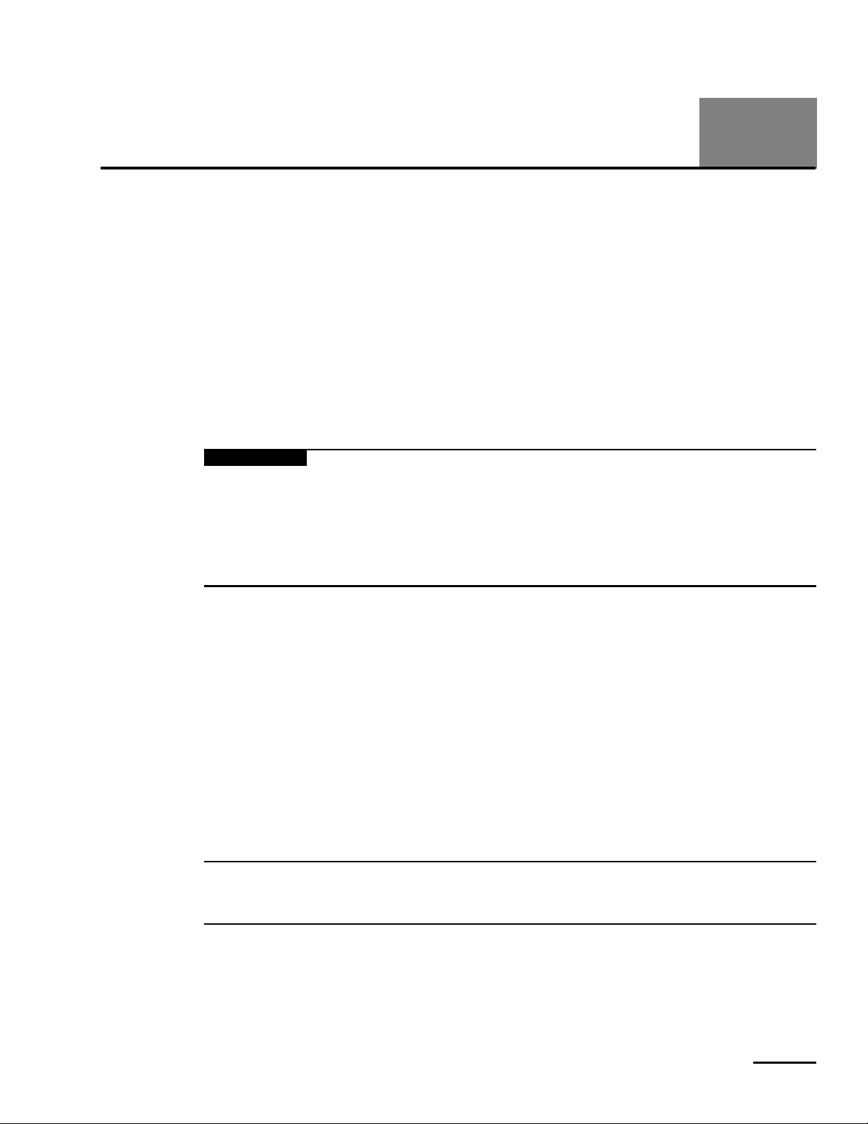
Power Supply Voltages
Voltage to be
Measured
+5 V R10 Pin 9 Pin 11 +4.95 to +5.05 V
+12 V R12 Pin 13 Pin 11 +11.88 to +12.12 V
+15 V R26 Pin 7 Pin 5 +14.85 to +15.15 V
–15 V R19 Pin 4 Pin 5 –15.15 to –14.85 V
(EMI 7200ae only)
Needs fuse
(4-030230-00) +15 V (R26) –15 V (R19) +12 V (R12)
TRANSFORMER
+15 V / –15 V
5 1 3 2 4
Potentiometer
+Out
+Out –S +S–S–Out
+S
COM
+15 V/–15 V
Positive
Lead
Negative
Lead
TRANSFORMER
4 2 3 1 5
Acceptable Range
+12 V
+Out –S –Out
+S
+12 V
–Out –Out
–Out +S –S
+5 V (R10)
TRANSFORMER
+5 V
(220/240 V only)
ISOLATION
TRANSFORMER
Power Fail Trip Points
Ventilator
Volt age
100 V ac 82 ± 1 V ac 90 V ac
115 V ac 95 ± 1 V ac 103.5 V ac
220 V ac 186 ± 1 V ac 198 V ac
240 V ac 204 ± 1 V ac 216 V ac
Power Fail Trip
Point
POST Value
R14
Power fail module
2-00385
Figure 11-1. Power Supply Voltage and Trip Point Calibration
11-2 7200 Series Ventilator System Service Manual 066317 Rev. A (03/04)
Page 3

Repair: Power Supply Assembly 11
11.3 Calibration of Power Fail Trip Point
The power fail module monitors the input power to the power supply assembly. If the input
power drops below the power fail trip point for 4 ms to 6 ms, the power fail module generates
a power fail signal, which signals the CPU.
Calibrate the trip point of the power fail module as follows. The calibration requires a variable
transformer (variac) with ground wire. A 0-140 V, 10 A variac is required for 100 and 115 V
ventilators, while a 0-280 V, 5 A variac is required for 220 and 240 V units.
NOTE:
Care must be taken when performing this procedure. When adjusting the variac voltage,
use a slow and steady motion to avoid lowering the voltage below the actual power fail trip
point, thereby invalidating the results.
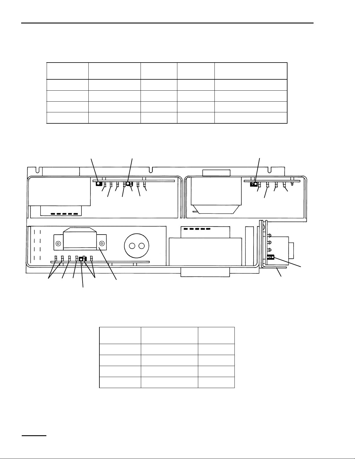
1. Remove ventilator top and back panels (Sections 19.1 through 19.4), and swing open lefthand panel (Section 9.1, steps 2 through 4). Disconnect all accessories (ac and dc
powered) from ventilator.
2. Connect electrical source to variac and connect variac to ventilator, as shown in Figure
11-2.
3. Adjust output of variac to applicable voltage (100, 115, 220, or 240 V).
4. Switch on ventilator power.
5. Connect DMM leads to a convenient location outside the ventilator in order to monitor
the input voltage, but place the leads as close to the ventilator’s power cord as possible.
Note the DMM voltage reading.
6. Remove DMM leads and place them on the “LINE” side of the surge suppressor, or on the
#2 tabs of the utility panel terminal block (if the unit is not equipped with a surge
suppressor). Note the DMM reading and compare it to the original reading. If the two
readings differ by more than 2 V, inspect terminal block, power cord, relay, and circuit
breaker for signs of oxidation. Clean or replace as necessary to correct.
7. While monitoring input voltage, slowly adjust variac to reduce input voltage until LEDs
on CPU PCB begin to flash. The point where CPU PCB LEDs begin to flash is the power fail
trip point. Verify that the DMM reading is within the applicable power fail trip point
range in Figure 11-1.
8. Raise variac voltage to where Power-On-Self-Test (POST) is initiated. Verify that the DMM
reading is less than or equal to the POST value given in Figure 11-1.
9. Repeat step 7 to verify power fail trip point.
10. Readjust output of variac to applicable voltage (100, 115, 220, or 240 V).
NOTE:
To avoid damaging the power fail trip point adjustment potentiometer (R14), use extreme
care when scraping off the existing torque seal.
11. If necessary, use a long, insulated, flat-bladed screwdriver to adjust power fail trip point
voltage by slowly turning the adjustment potentiometer (R14).
12. Repeat steps 7 through 11 until trip point and POST voltages are acceptable.
13. Seal potentiometer (R14) with torque seal (P/N 4-004017-00).
14. Turn off power switch to ventilator.
15. Disconnect ventilator and variac from wall power.
066317 Rev. A (03/04) 7200 Series Ventilator System Service Manual 11-3
Page 4
11 Repair: Power Supply Assembly
16. Reattach all panels (Section 19), hardware, and accessories (Section 3) to the ventilator.
17. Connect external pneumatic and electrical sources to ventilator.
18. Refer to performance verification procedures in Section 7 to verify that ventilator
is operational.
Top cabinet
panel
Top cover
ac input
Variac
Voltmeter
Surge
suppressor
Left-hand
panel
Back
panels
Power cord
Figure 11-2. Power Fail Trip Point Calibration Test Setup
11.4 Removal/Installation of Top-Mounted Surge Suppressor
A surge suppressor filters voltage spikes. In those ventilators with a surge suppressor, the 100/
115 V suppressor is always mounted near the top of the ventilator, while the 220/240 V
suppressor may be mounted near the top or it may be integral to the utility panel. The
following subsections discuss the service of top-mounted surge suppressors. Refer to
Section 12.8 to service the 220/240 V surge suppressor integral to the utility panel.
11.4.1 100/115 V Surge Suppressor
Remove the 100/115 V surge suppressor as follows. Install by reversing removal procedures.
1. Remove ventilator top and back panels (Sections 19.1 through 19.4), and swing open lefthand panel (Section 9.1, steps 2 through 4).
2. Disconnect wires that are attached to the surge suppressor “LOAD” terminals from
interconnect harness (if present) or from the surge suppressor (blue wires from “N”, brown
wires from “L1”).
2-00386
11-4 7200 Series Ventilator System Service Manual 066317 Rev. A (03/04)
Page 5
Repair: Power Supply Assembly 11
3. Pull power supply ac harness down through bottom of surge suppressor bracket. (Note
that harness grommet is removable through slot in the edge of the bracket.)
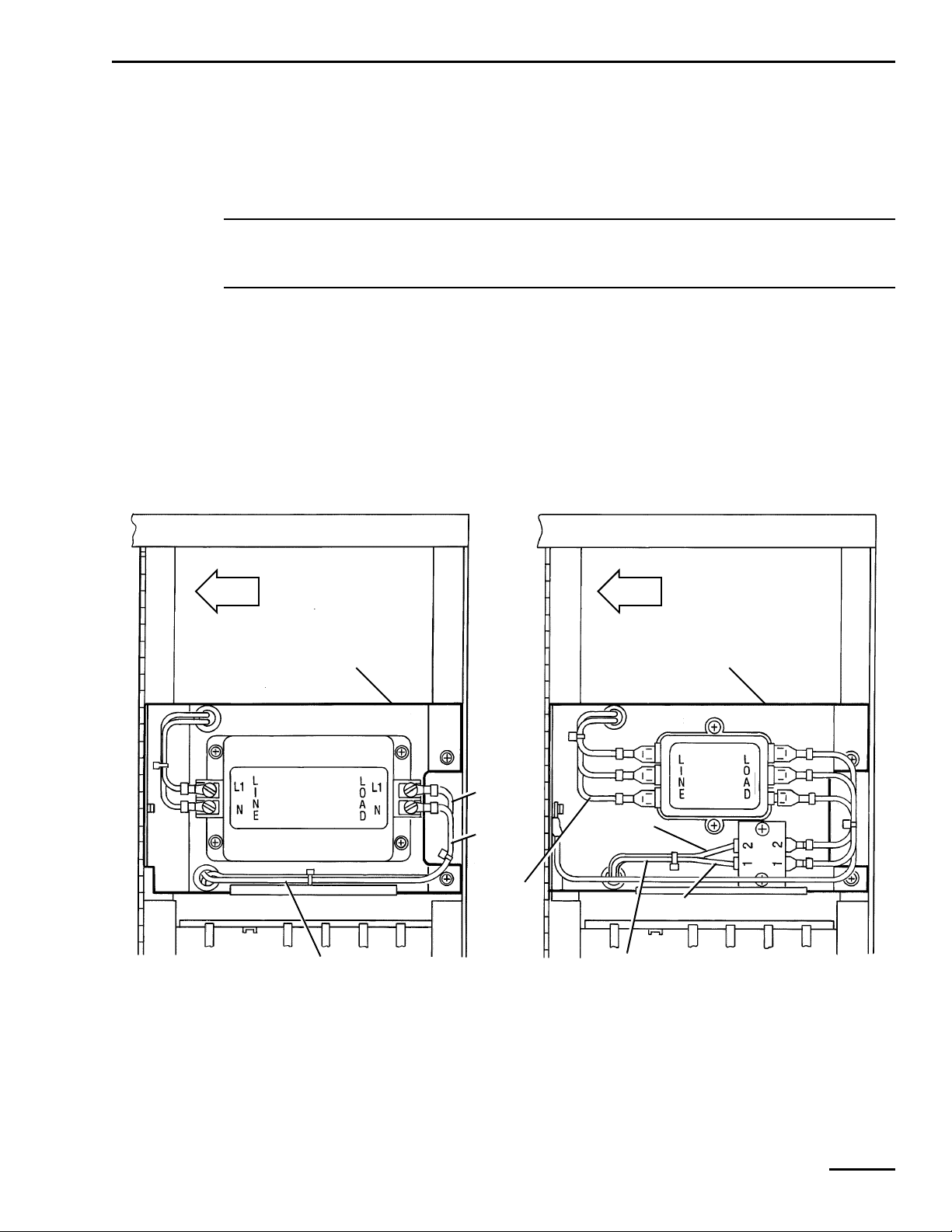
4. Disconnect the following wires from utility panel terminal block (Figure 11-4):
a. Blue wire in surge suppressor harness from “N1” terminal.
b. Brown wire in surge suppressor harness from “L2” terminal.
NOTE:
The locations of utility panel terminals are shown on the terminal block label on the
ventilator cabinet divider wall.
5. Remove harness from wire clips on ventilator cabinet divider wall, and pull harness up
through bottom of surge suppressor bracket.
6. Remove screw and lock washer that attach front portion of surge suppressor bracket to
ventilator console hinge panel.
7. Loosen two screws (one on either side of surge suppressor assembly) that attach two
suppressor bracket clamps to surge suppressor bracket (Figure 11-5).
8. Remove surge suppressor by lifting its front edge and sliding clamps off rear ventilator
cabinet lip.
FRONT
Surge
suppressor
bracket
Brown
wires
Blue
wires
Green/
yellow
wire
Power supply
ac harness
FRONT
Surge
suppressor
bracket
Brown
wires
Blue wires
Power supply
ac harness
100/115 V Unit 220/240 V Unit
Interconnect
harness
ground wire
2-00387
Figure 11-3. Disconnecting Top-Mounted Surge Suppressor Harness
066317 Rev. A (03/04) 7200 Series Ventilator System Service Manual 11-5
Page 6
11 Repair: Power Supply Assembly
11.4.2 220/240 V Surge Suppressor
If the 220/240 V surge suppressor is mounted near the top of the ventilator, remove it as
follows. Install by reversing removal procedures.
1. Remove ventilator top and back panels (Sections 19.1 through 19.4), and swing open lefthand panel (Section 9.1, steps 2 through 4).
2. Disconnect wires that are attached to surge suppressor “LOAD” terminals from
interconnect harness (if present) or from surge suppressor (blue wires from “N”, brown
wires from “L1”).
3. Pull surge suppressor harness up through bottom of surge suppressor bracket. (Note that
harness grommet is removable through slot in the edge of the bracket.)
4. Disconnect these wires from utility panel terminal block (Figure 11-4):
5. Blue wire in surge suppressor harness from “N1” terminal.
6. Brown wire in surge suppressor harness from “L2” terminal.
7. Disconnect green/yellow wire from green/yellow power cord ground wire (Figure 11-3).
8. Pull harness up through bottom of surge suppressor bracket.
9. Remove screw and washer that attach front portion of surge suppressor and interconnect
harness ground wire to ventilator console hinge panel (Figure 11-5).
10. Remove surge suppressor by lifting its front edge and sliding clamps off rear ventilator
cabinet lip.
N
1
2
3
4
1
2
3
4
20038 REV A
2-00388
Ground stud
2-00310
L
L
N
DIVIDER WALL
N
SWITCHED
L
SWITCHED
L
UNSWITCHED
N
UNSWITCHED
REAR OF UNIT
Terminal Block Label
Figure 11-4. Disconnecting Harnesses from Utility Panel Terminal Block
11-6 7200 Series Ventilator System Service Manual 066317 Rev. A (03/04)
Page 7
Repair: Power Supply Assembly 11
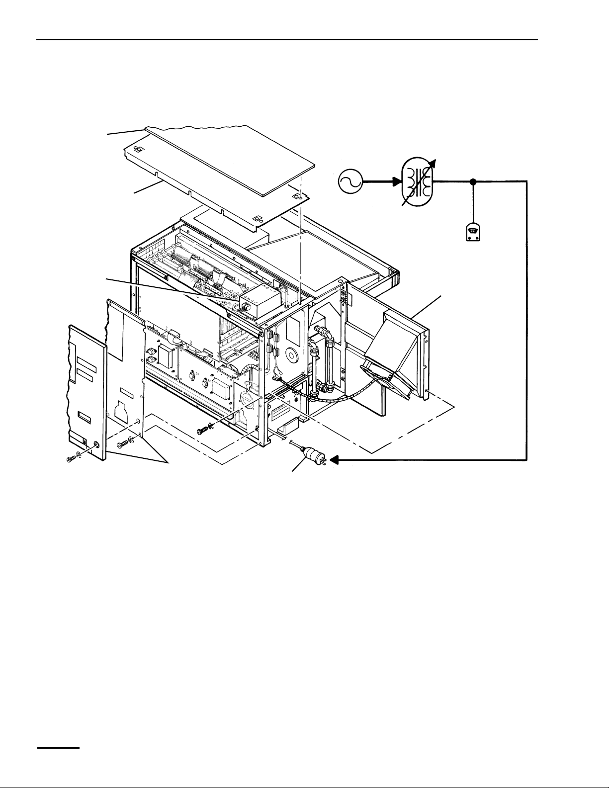
11.5 Removal/Installation of Power Supply Assembly
Remove the power supply assembly from the ventilator as follows. Install by reversing
removal procedures.
1. Disconnect power supply ac harness as applicable, depending on configuration:
• From utility panel terminal block (blue wires) from “N1”, brown wire(s) from “L2” as in Figure
11-4.
• From interconnect harness.
• From surge suppressor terminal block
NOTE:
The locations of utility panel terminals are shown on the terminal block label on the
ventilator cabinet divider wall.
2. Remove three screws and washers that attach rear bottom edge of power supply
to ventilator (Figure 11-5).
Warning
The power supply assembly is very heavy. Be careful when lifting the power supply assembly
out of the ventilator.
Surge
suppressor
Suppressor
bracket
clamps
3. Remove the screws to the utility panel and slide it to the left side of the ventilator.
220/240 V
power supply
Power supply
assembly
066317 Rev. A (03/04) 7200 Series Ventilator System Service Manual 11-7
110/115 V
power supply
ac harness
ac harness
2-00389
Page 8

11 Repair: Power Supply Assembly
Figure 11-5. Removing Power Supply Assembly and Top-Mounted External Surge Suppressor
4. Slide power supply assembly towards rear of ventilator to disengage front bottom edge
from three retaining clips.
5. Carefully remove power supply assembly by sliding it to the left side of the ventilator and
removing it out the rear.
11.6 Removal/Installation of Power Supply Modules and Isolation Transformer
Three removable power supply modules are mounted to the power supply assembly
baseplate. One of these modules, the +5 V module, has three removable components: a fuse
plate, a power failure module, and an isolation transformer.
NOTE:
When installing power supply modules to baseplate, be sure nonconductive heatsink
compound (P/N 4-004434-00) between baseplate and power modules is semi-sticky and
free of debris and large area voids.
11.6.1 +5 V Module
Remove the +5 V module from the power supply assembly as follows, referring to Figure 11-6.
Install by reversing removal procedures.
1. Remove power supply assembly from ventilator (Section 11.5).
2. Separate fuse plate from +5 V module by removing two screws and lockwashers.
3. Separate mounting plate and power fail module from +5 V module by removing two
nuts and lockwashers.
4. Label and unsolder blue and brown wires of power supply ac harness from +5 V
module transformer.
5. Label and unsolder power supply dc harness from +5 V module circuit board.
6. Separate +5 V module from baseplate by removing four attaching screws.
7. If removal of power fail module or isolation transformer is required, refer to Section 11.6.4
or 11.6.5, as applicable.
11.6.2 +12 V Module
Remove the +12 V module from the power supply assembly as follows, referring to Figure
11-6. Install by reversing removal procedures.
1. Remove power supply assembly from ventilator (Section 11.5).
2. Label and unsolder blue and brown wires of power supply ac harness from +12 V module
transformer.
3. Label and unsolder power supply dc harness from +12 V module circuit board.
4. Separate +12 V module from baseplate by removing four attaching screws.
11-8 7200 Series Ventilator System Service Manual 066317 Rev. A (03/04)
Page 9

Repair: Power Supply Assembly 11
11.6.3 ±15 V Module
Remove the ±15 V module from the power supply assembly as follows, referring to Figure
11-6. Install by reversing removal procedures.
1. Remove power supply assembly from ventilator (Section 11.5).
2. Label and unsolder blue and brown wires of power supply ac harness from ±15 V module
transformer.
NOTE:
Replace fuse in In-line fuse holder (EMI 7200ae Ventilators only), as applicable.
3. Label and unsolder power supply dc harness from ±15 V module circuit board.
4. Separate ±15 V module from baseplate by removing four attaching screws.
5. If present, remove fuse replacement caution tag from ±15 V module, and attach caution
tag with a cable tie (P/N 4-000003-00) to new ±15 V module.
066317 Rev. A (03/04) 7200 Series Ventilator System Service Manual 11-9
Page 10

11 Repair: Power Supply Assembly
Power fail
module
Fuse plate
+5 V
Mounting
plate
transformer
±12 V
transformer
±12 V
module
±15 V
module
Base plate
Isolation
transformer
(220/240 V only)
Transformer
bracket
±15 V
transformer
+5 V
module
±15 V
module
2-00390
Figure 11-6. Removing Power Supply Modules
11.6.4 Power Fail Module
Remove the power fail module from the power supply assembly as follows, referring to Figure
11-6 and Figure 11-7. Install by reversing removal procedures.
1. Remove power supply assembly from ventilator (Section 11.2).
2. Label and remove blue and brown wires in power supply ac harness from power fail
module transformer.
11-10 7200 Series Ventilator System Service Manual 066317 Rev. A (03/04)
Page 11

Repair: Power Supply Assembly 11
3. Label and remove black and white wires in power supply dc harness from power fail
module circuit board.
4. Separate power fail module from +5 V module by removing two attaching screws and
lockwashers.
11.6.5 Isolation Transformer (220/240 V Power Supply)
Remove the isolation transformer from the power supply as follows, referring to Figure 11-6
and Figure 11-7. Install by reversing removal procedures.
1. Remove power supply assembly from ventilator (Section 11.5).
2. Label and remove wires that connect isolation transformer to power supply.
3. Remove transformer bracket by removing two screws and two nuts.
4. Remove isolation transformer from transformer bracket by removing four nuts from studs
of isolation transformer.
Power fail module in 220/240 V ac power supply with isolation transformer is wired with 13D blue
wire to + neutral terminal and 14D brown wire to 115 V terminal.
220/240 V ac
80188-based units
with isolation
transformer
13D blue
Power fail module in 220/240 V ac power supply with isolation transformer is wired with 13D blue
wire to + neutral terminal and 14D brown wire to 115 V terminal.
220/240 V ac
8088-based units
with isolation
transformer
3D blue
1D blue
14D brown
2D blue
Figure 11-7. Isolation Transformer Terminal Connections
2-00391
066317 Rev. A (03/04) 7200 Series Ventilator System Service Manual 11-11
Page 12

11 Repair: Power Supply Assembly
This page is intentionally blank.
11-12 7200 Series Ventilator System Service Manual 066317 Rev. A (03/04)
Page 13

SECTION
SECTION
Repair: Utility Panel Assembly 12
The utility panel distributes ac power from facility power outlets to the power supply and
other ventilator components. In addition, the utility panel contains two rechargeable
batteries to operate alarm functions and maintain ventilator data in memory during power
interruption.
This section includes removal and installation procedures for the utility panel assembly.
Before repairing the utility panel assembly, familiarize yourself with the warnings, cautions,
and general repair instructions in Section 8.
Warning
To prevent personal injury and equipment or property damage, ensure that electrical power
sources and pneumatic sources are disconnected from the ventilator before servicing.
NOTE:
Any time you disconnect the batteries, be sure to:
• Perform a monitor volume calibration before placing the monitor back into service
(ventilators with 7250 Metabolic Monitors only). Refer to the 7250 Operator’s Manual.
• Reset the time on the calendar-clock after the batteries are reconnected.
• Delete 1401 error code from BBR.
12
12.1 Removal/Installation of Utility Panel Assembly
Remove the utility panel assembly as follows. Install by reversing removal procedures.
1. Remove top cabinet panel and top cover, as applicable (Section 19.1.1), and back panel
and inner back panel, as applicable (Section 19.2.1), and swing open left
panel (Section 9.1).
2. Disconnect utility panel harness from J11 on motherboard.
NOTE:
The locations of utility panel terminals are shown on the terminal block label on the
ventilator cabinet divider wall.
3. If ventilator has a surge suppressor mounted near top of ventilator, disconnect these surge
suppressor wires from utility panel terminal block (Figure 12-1 and Figure 12-3):
a. Blue wire from “N1” terminal.
b. Brown wire from “L2” terminal.
066317 Rev. A (03/04) 7200 Series Ventilator System Service Manual 12-1
Page 14

12 Repair: Utility Panel Assembly
4. If ventilator does not have a surge suppressor mounted near top of ventilator, disconnect
these ac harness wires from utility panel terminal block (Figure 12-1 and Figure 12-3):
a. Blue wire(s) from “N1” terminal.
b. Brown wire(s) from “L2” terminal.
5. Disconnect these humidifier outlet harness wires from utility panel terminal block:
a. Blue wire from “N1” terminal.
b. Brown wire from “L2” terminal.
6. Free these green or green/yellow ground wires from rear utility panel ground stud by
removing nut and washer (Figure 12-1):
a. Humidifier outlet harness ground wire.
b. Console shield wire.
c. Surge suppressor ground wire (in 220/240 V units with top-mounted surge
suppressors).
Caution
When removing or installing the battery tray, take care to prevent damage to the battery
terminal wire insulation.
Ground stud
Figure 12-1. Utility Panel Terminal Block
2-00310
N
L
L
N
DIVIDER WALL
N
SWITCHED
L
SWITCHED
L
UNSWITCHED
N
UNSWITCHED
REAR OF UNIT
20038 REV A
Terminal Block Label
1
2
3
4
1
2
3
4
2-00388
12-2 7200 Series Ventilator System Service Manual 066317 Rev. A (03/04)
Page 15

Repair: Utility Panel Assembly 12
7. If ventilator has a compressor, disconnect compressor electrical circuit from
utility panel as follows:
a. Remove compressor pedestal outer back panel by pulling out on upper corners of back
panel until ball studs disengage from catches in compressor pedestal cabinet.
b. Remove inner back panel by removing 8 (later version) or 12 (earlier version)
attaching screws and washers.
c. Disconnect utility panel harness receptacle from compressor harness connector,
reaching into upper compressor compartment at back of compressor pedestal.
d. Push utility panel harness receptacle up through square hole at top of compressor
pedestal and fully into utility panel.
e. Remove two screws that attach front of utility panel to ventilator. Remove cord
bracket. Slide utility panel out left side of ventilator.
8. If ventilator does not have a compressor, remove two screws that attach front of utility
panel, cover plate, and cord bracket to ventilator (Figure 12-3). Remove cord bracket and
slide utility panel out of left side of ventilator.
Brown wire to
“L2” terminal
Blue wire to
“N1” terminal
Surge
suppressor
Blue wire to
“N1” terminal
Brown wire to
“L2” terminal
Green/Yellow wire to
utility panel ground stud
100/115 V Unit 220/240 V Unit
Figure 12-2. Disconnecting Top-Mounted Surge Suppressor Harness
Surge
suppressor
2-00387
066317 Rev. A (03/04) 7200 Series Ventilator System Service Manual 12-3
Page 16

12 Repair: Utility Panel Assembly
Utility panel
harness
Cable strap
Fan power
cord
Utility
panel
assembly
Motherboard
J11 connector
Compressor
harness
Cover plate
(units without
compressor)
Battery
liner
Batteries
Figure 12-3. Removing Utility Panel Assembly
Cord
bracket
2-00392
12-4 7200 Series Ventilator System Service Manual 066317 Rev. A (03/04)
Page 17

Repair: Utility Panel Assembly 12
12.2 Power Switch
The power switch applies filtered ac to ventilator components. Replace the power switch
every 10,000 hours of ventilator operation; it is part of the 10,000-hour preventive
maintenance kit. Remove and install it as follows, referring to Figure 12-4.
1. Disconnect wires from power switch. Remove power switch by pressing top and bottom of
switch while pushing out.
2. Install new switch and reconnect wires.
3. Test new switch:
a. Turn switch on to ensure power disconnect audible alarm functions. Power cord
should not be connected to facility power.
b. Turn switch off.
c. Reconnect electrical power to ventilator.
d. Turn switch on and off to ensure it actuates freely, and ventilator runs POST.
e. Disconnect electrical power.
NOTE:
If new switch does not fit, you may need to file opening for switch. To do so, remove utility
panel and use a metal file to lightly file right or left side only of aluminum plate opening. Use
a piece of sandpaper to smooth rough edges. Carefully blow out filings from utility panel.
4. Reinstall utility panel in ventilator.
12.3 Ventilator Elapsed Time Meter
The ventilator elapsed time meter (ETM) measures the hours that the ventilator operates.
A second elapsed time meter in the compressor compartment measures the hours the
compressor operates (Section 16.7). Remove the ventilator elapsed time meter as follows,
referring to Figure 12-4. Install by reversing removal procedures.
1. Disconnect wires from elapsed time meter.
2. Remove elapsed time meter by removing three attaching screws, lockwashers, and nuts.
12.4 Circuit Breaker
The circuit breaker protects the ventilator components from excessive current. Remove the
circuit breaker as follows, referring to Figure 12-4. Install by reversing removal procedures.
1. Disconnect wires from circuit breaker.
2. Remove circuit breaker by removing attaching nut.
12.5 Power Line Filter
The power line filter filters ac power. Remove the power line filter as follows, referring to
Figure 12-4. Install by reversing removal procedures.
1. Remove utility panel from ventilator (Section 12.1).
2. Disconnect wires from power line filter.
3. Remove power line filter by removing attaching nut and lockwashers from the two studs
on utility panel cover.
066317 Rev. A (03/04) 7200 Series Ventilator System Service Manual 12-5
Page 18

12 Repair: Utility Panel Assembly
12.6 Power Relay
The power relay applies ac power to ventilator components. Remove the power relay as
follows, referring to Figure 12-4. Install by reversing removal procedures.
1. Remove utility panel from ventilator (Section 12.1).
2. Disconnect wires from power relay.
3. Remove power relay by removing two nuts, lockwashers, and washers.
BLK
To
humidifier
harness
GRN/YEL
To
console
shield
2D
BLU
(to ETM)
BLU
2F
BLU
1D BRN
BRN
BLK (to ETM)
1C BRN
(not used)(not used)
Power relay
1C BRN
1F BRN
1F BRN 27 WHT
Power switch
(not used)
7 WHT
Elapsed
time meter
1F BRN
1D BRN
2D BLU
2F BLU
2F BLU
2D BLU
1F BRN
1D BRN
1A
BLU
2A
BRN
Power
line filter
2B
BRN
1B
BLU
Figure 12-4. Removing Utility Panel Components
Circuit breaker
4
3
1
2
110/115 V
4
3
12
220/240 V
2B BRN
1B BLU
1B BLU
2B BRN
2-00393
12-6 7200 Series Ventilator System Service Manual 066317 Rev. A (03/04)
Page 19

Repair: Utility Panel Assembly 12
12.7 Utility Panel Harness
The utility panel harness interconnects the motherboard, the analog output connector, the
batteries, the utility panel terminal block, the fan motion sensor alarm harness (if so
equipped), the compressor compartment electronics, the alarm volume potentiometer (R1),
and the EST switch. Later versions of this harness also include an In-line fuse. R1 and the EST
switch are part of the harness.
12.7.1 Removal/Installation
Remove the utility panel harness as follows, referring to Figure 12-5. Install by reversing
removal procedures.
1. Remove utility panel from ventilator (Section 12.1).
2. Remove batteries and battery liner by sliding them out from utility panel, then
disconnecting batteries from battery connector.
3. Disconnect harness (two white wires) from power switch.
4. Free EST switch from utility panel by unscrewing dress nut, then removing nut and
washers.
NOTE:
If it is necessary to use a tool to remove dress nut, cover nut with cloth to avoid scratching it.
5. Free audio alarm volume control from utility panel:
a. Using 0.050-in. hex driver, loosen setscrews in knob. Remove knob.
b. Remove nut and washers, and remove control from utility panel.
6. Free analog output connector from utility panel by removing two standoff posts
and attaching hardware.
7. Disconnect harness from utility panel terminal block (Figure 12-1):
a. Disconnect blue wire from “N4” terminal.
b. Disconnect brown wire from “L3” terminal.
Caution
When installing the utility panel harness, be sure it is free and clear of the fan blades.
NOTE:
When installing a later-version harness in a ventilator without an active fan alarm, cover fan
connector with insulating tape.
066317 Rev. A (03/04) 7200 Series Ventilator System Service Manual 12-7
Page 20

12 Repair: Utility Panel Assembly
12.7.2 Fuse Replacement
Later versions of this harness include an In-line fuse, which is housed in a capsule molded
into harness. To access fuse (Figure 12-5), pull ends of capsule apart. Replace fuse,
as applicable.
Caution
When removing or installing the battery tray, take care to prevent damage to the battery
terminal wire insulation.
1C BRN
To motherboard
To electronics
compartment fan
motion detector
alarm harness
Alarm volume
control
Analog output
connector
EST
switch
Blue wire
Brown wire
7 WHT
27 WHT
1F BRN
Power
switch
Dress nut
for EST
switch
Battery
connector
In-line
fuse
P21
To
compressor
compartment
Alarm
volume
knob
2-00394
Figure 12-5. Removing Utility Panel Harness
12-8 7200 Series Ventilator System Service Manual 066317 Rev. A (03/04)
Page 21

Repair: Utility Panel Assembly 12
12.8 220/240 V Line Voltage Filter Receptacle (Later Versions)
Follow these instructions to remove the 220/240 V line voltage filter receptacle (if so
equipped), referring to Figure 12-6. Install by reversing removal procedures.
1. Remove utility panel from ventilator (Section 12.1).
2. Unplug ventilator power cord from face of utility panel.
3. Disconnect wires from line voltage filter receptacle.
4. Remove two screws holding power cord mount and line voltage filter receptacle in place.
Remove line voltage filter receptacle.
12.9 Batteries
NOTE:
The batteries are now available only in a kit (P/N 4-021526-00), which includes two
batteries and a return mailer. Always replace both batteries at the same time.
The batteries provide dc power backup to protect ventilator data and to activate the audio
alarm if the facility power or ventilator internal electrical system fails. Replace the batteries
every 10,000 hours of ventilator operation; they are part of the 10,000-hour preventive
maintenance kit.
Remove the batteries as follows, referring to Figure 12-6. Install by reversing
removal procedures:
1. Remove top cabinet panel and top cover, as applicable (Section 19.1.1), and back panel
and inner back panel, as applicable (Section 19.2.1).
Caution
When removing or installing the battery tray, take care to prevent damage to the battery
terminal wire insulation.
2. Remove batteries and battery liner by sliding them out from utility panel, then
disconnecting batteries from battery connector.
3. Clean battery terminals, if oxidized.
4. If battery voltage is <2.0 V, replace both batteries.
5. Repackage used batteries (positive terminals taped) as the new batteries were packaged.
Return them for recycling in mailer supplied (U.S.A. or Canada), or dispose of
appropriately (outside U.S.A. and Canada).
Warning
To avoid accidental shorting and to prevent fire hazard, do not merely discard the batteries.
Instead, repackage the used batteries in the same way the new batteries were packaged
(positive terminals taped, terminals in foam). Recycle them or dispose of them
appropriately.
066317 Rev. A (03/04) 7200 Series Ventilator System Service Manual 12-9
Page 22

12 Repair: Utility Panel Assembly
Wires to
line voltage
filter receptacle
BLU
GRN/YEL
BRN
Line voltage
filter receptacle
Power cord
Batteries
mount
Figure 12-6. Removing Line Voltage Filter from 220/240 V Utility Panel
Power cord
2-00395
12-10 7200 Series Ventilator System Service Manual 066317 Rev. A (03/04)
 Loading...