

Page 1
User Manual
Puritan Bennett
560 Ventilator
TM
Page 2

COVIDIEN, COVIDIEN with logo, and the Covidien logo and Positive Results for Life are U.S. and internationally registered trademarks of Covidien AG. ™* brands are trademarks of their respective owners.
All other brands are trademarks of a Covidien company.
The information contained in this manual is the sole property of Covidien and may not be duplicated
without permission. This manual may be revised or replaced by Covidien at any time and without
notice. You should ensure that you have the most current applicable version of this manual; if in
doubt, contact Covidien's Technical Support department or visit the product manuals web page at:
www.medtronic.com/covidien/support/product-manuals
While the information set forth herein is believed to be accurate, it is not a substitute for the exercise
of professional judgment.
The ventilator should be operated and serviced only by trained professionals. Covidien’s sole responsibility with respect to the ventilator, and its use, is as stated in the limited warranty provided.
Nothing in this manual shall limit or restrict in any way Covidien’s right to revise or otherwise change
or modify the equipment (including its software) described herein, without notice. In the absence of
an express, written agreement to the contrary, Covidien has no obligation to furnish any such revisions, changes, or modifications to the owner or user of the equipment (including its software)
described herein.
To obtain information about a warranty, if any, contact Covidien Technical Services at 1 800 635 5267
or your local representative.
Purchase of this instrument confers no express or implied license under any Covidien patent to use
the instrument with any ventilator that is not manufactured or licensed by Covidien.
Page 3

Table of Contents
Preface
Purpose of This Manual . . . . . . . . . . . . . . . . . . . . . . . . . . . . . . . . . . . . . . . . . . . . . . . . . . . . . . xi
Qualification of Personnel . . . . . . . . . . . . . . . . . . . . . . . . . . . . . . . . . . . . . . . . . . . . . . . . . . . . xi
Warranty . . . . . . . . . . . . . . . . . . . . . . . . . . . . . . . . . . . . . . . . . . . . . . . . . . . . . . . . . . . . . . . . . . . . xi
Extended Service . . . . . . . . . . . . . . . . . . . . . . . . . . . . . . . . . . . . . . . . . . . . . . . . . . . . . . . . . . . . xi
Service Centers . . . . . . . . . . . . . . . . . . . . . . . . . . . . . . . . . . . . . . . . . . . . . . . . . . . . . . . . . . . . . . xii
1 Safety Information
1.1 Definitions . . . . . . . . . . . . . . . . . . . . . . . . . . . . . . . . . . . . . . . . . . . . . . . . . . . . . . . . . . . . . . . . . 1-1
1.2 Warnings . . . . . . . . . . . . . . . . . . . . . . . . . . . . . . . . . . . . . . . . . . . . . . . . . . . . . . . . . . . . . . . . . . . 1-1
1.2.1 General Warnings Regarding Use of Equipment . . . . . . . . . . . . . . . . . . . . . . . . . . . . . . . . . . . . . . . 1-1
1.2.2 Warnings Regarding Installation and Environment of Use . . . . . . . . . . . . . . . . . . . . . . . . . . . . .1-4
1.2.3 Warnings Regarding Electrical Power Supplies . . . . . . . . . . . . . . . . . . . . . . . . . . . . . . . . . . . . . . . . 1-7
1.2.4 Warnings Regarding Hoses and Accessories . . . . . . . . . . . . . . . . . . . . . . . . . . . . . . . . . . . . . . . . . .1-8
1.2.5 Warnings Regarding Settings . . . . . . . . . . . . . . . . . . . . . . . . . . . . . . . . . . . . . . . . . . . . . . . . . . . . . . . .1-11
1.2.6 Warnings Regarding PC Connection and USB Memory Devices . . . . . . . . . . . . . . . . . . . . . .1-14
1.2.7 Warnings Regarding Maintenance . . . . . . . . . . . . . . . . . . . . . . . . . . . . . . . . . . . . . . . . . . . . . . . . . .1-14
1.2.8 Warnings Regarding Oxygen . . . . . . . . . . . . . . . . . . . . . . . . . . . . . . . . . . . . . . . . . . . . . . . . . . . . . . . .1-17
1.2.9 Warnings Regarding Electromagnetic Interference . . . . . . . . . . . . . . . . . . . . . . . . . . . . . . . . . . .1-19
1.3 Symbols and Markings . . . . . . . . . . . . . . . . . . . . . . . . . . . . . . . . . . . . . . . . . . . . . . . . . . . . . 1-19
1.4 Labels (Identification and Instruction Information) . . . . . . . . . . . . . . . . . . . . . . . . . . 1-24
2 Ventilator Overview
2.1 Indications for Use . . . . . . . . . . . . . . . . . . . . . . . . . . . . . . . . . . . . . . . . . . . . . . . . . . . . . . . . . . 2-1
2.1.1 Target Patients . . . . . . . . . . . . . . . . . . . . . . . . . . . . . . . . . . . . . . . . . . . . . . . . . . . . . . . . . . . . . . . . . . . . . . .2-1
2.1.2 Target Environments . . . . . . . . . . . . . . . . . . . . . . . . . . . . . . . . . . . . . . . . . . . . . . . . . . . . . . . . . . . . . . . . .2-1
2.1.3 Target Operators . . . . . . . . . . . . . . . . . . . . . . . . . . . . . . . . . . . . . . . . . . . . . . . . . . . . . . . . . . . . . . . . . . . . .2-2
2.2 Contraindications . . . . . . . . . . . . . . . . . . . . . . . . . . . . . . . . . . . . . . . . . . . . . . . . . . . . . . . . . . . 2-2
2.3 Operational Use . . . . . . . . . . . . . . . . . . . . . . . . . . . . . . . . . . . . . . . . . . . . . . . . . . . . . . . . . . . . 2-3
2.3.1 Safety Net . . . . . . . . . . . . . . . . . . . . . . . . . . . . . . . . . . . . . . . . . . . . . . . . . . . . . . . . . . . . . . . . . . . . . . . . . . . .2-3
2.3.2 Settings . . . . . . . . . . . . . . . . . . . . . . . . . . . . . . . . . . . . . . . . . . . . . . . . . . . . . . . . . . . . . . . . . . . . . . . . . . . . . . 2-3
2.3.3 Oxygen Enrichment . . . . . . . . . . . . . . . . . . . . . . . . . . . . . . . . . . . . . . . . . . . . . . . . . . . . . . . . . . . . . . . . . . 2-3
2.3.4 Breathing Circuit . . . . . . . . . . . . . . . . . . . . . . . . . . . . . . . . . . . . . . . . . . . . . . . . . . . . . . . . . . . . . . . . . . . . . 2-3
2.4 Device Classification . . . . . . . . . . . . . . . . . . . . . . . . . . . . . . . . . . . . . . . . . . . . . . . . . . . . . . . . 2-4
2.5 Front Panel . . . . . . . . . . . . . . . . . . . . . . . . . . . . . . . . . . . . . . . . . . . . . . . . . . . . . . . . . . . . . . . . . 2-5
2.6 Back Panel . . . . . . . . . . . . . . . . . . . . . . . . . . . . . . . . . . . . . . . . . . . . . . . . . . . . . . . . . . . . . . . . . . 2-6
2.7 Control Panel . . . . . . . . . . . . . . . . . . . . . . . . . . . . . . . . . . . . . . . . . . . . . . . . . . . . . . . . . . . . . . . 2-7
2.8 Ventilation Menu . . . . . . . . . . . . . . . . . . . . . . . . . . . . . . . . . . . . . . . . . . . . . . . . . . . . . . . . . . . 2-8
2.9 Alarm Menu . . . . . . . . . . . . . . . . . . . . . . . . . . . . . . . . . . . . . . . . . . . . . . . . . . . . . . . . . . . . . . . . 2-9
2.10 Waveforms Menu . . . . . . . . . . . . . . . . . . . . . . . . . . . . . . . . . . . . . . . . . . . . . . . . . . . . . . . . . . 2-10
User Manual iii
Page 4

Table of Contents
2.11 USB Memory Device Menu . . . . . . . . . . . . . . . . . . . . . . . . . . . . . . . . . . . . . . . . . . . . . . . . . 2-11
2.12 If Ventilator Failure Occurs . . . . . . . . . . . . . . . . . . . . . . . . . . . . . . . . . . . . . . . . . . . . . . . . . 2-11
3 Alarms and Troubleshooting
3.1 Overview . . . . . . . . . . . . . . . . . . . . . . . . . . . . . . . . . . . . . . . . . . . . . . . . . . . . . . . . . . . . . . . . . . . 3-1
3.2 Alarm Level of Priority . . . . . . . . . . . . . . . . . . . . . . . . . . . . . . . . . . . . . . . . . . . . . . . . . . . . . . 3-2
3.3 Alarm Display . . . . . . . . . . . . . . . . . . . . . . . . . . . . . . . . . . . . . . . . . . . . . . . . . . . . . . . . . . . . . . 3-3
3.4 Alarm Logs Menu . . . . . . . . . . . . . . . . . . . . . . . . . . . . . . . . . . . . . . . . . . . . . . . . . . . . . . . . . . . 3-4
3.5 Pausing the Audible Portion of Alarms . . . . . . . . . . . . . . . . . . . . . . . . . . . . . . . . . . . . . . . 3-6
3.6 Pausing and Resetting Alarms . . . . . . . . . . . . . . . . . . . . . . . . . . . . . . . . . . . . . . . . . . . . . . . 3-7
3.7 Reactivating Alarms . . . . . . . . . . . . . . . . . . . . . . . . . . . . . . . . . . . . . . . . . . . . . . . . . . . . . . . . 3-8
3.8 Overview of Alarms . . . . . . . . . . . . . . . . . . . . . . . . . . . . . . . . . . . . . . . . . . . . . . . . . . . . . . . . . 3-9
3.9 Troubleshooting . . . . . . . . . . . . . . . . . . . . . . . . . . . . . . . . . . . . . . . . . . . . . . . . . . . . . . . . . . 3-15
3.9.1 Alarms . . . . . . . . . . . . . . . . . . . . . . . . . . . . . . . . . . . . . . . . . . . . . . . . . . . . . . . . . . . . . . . . . . . . . . . . . . . . . .3-15
3.9.2 Additional Troubleshooting . . . . . . . . . . . . . . . . . . . . . . . . . . . . . . . . . . . . . . . . . . . . . . . . . . . . . . . . .3-25
4 Installation and Assembly
4.1 Ventilator Startup Procedure . . . . . . . . . . . . . . . . . . . . . . . . . . . . . . . . . . . . . . . . . . . . . . . . 4-1
4.2 Connecting to External AC Power . . . . . . . . . . . . . . . . . . . . . . . . . . . . . . . . . . . . . . . . . . . . 4-3
4.3 Connecting to an External DC Power Source . . . . . . . . . . . . . . . . . . . . . . . . . . . . . . . . . 4-6
4.4 Patient Circuit . . . . . . . . . . . . . . . . . . . . . . . . . . . . . . . . . . . . . . . . . . . . . . . . . . . . . . . . . . . . . . 4-8
4.4.1 Choosing the Patient Circuit Type . . . . . . . . . . . . . . . . . . . . . . . . . . . . . . . . . . . . . . . . . . . . . . . . . . . . 4-9
4.4.2 Installing the Patient Circuit . . . . . . . . . . . . . . . . . . . . . . . . . . . . . . . . . . . . . . . . . . . . . . . . . . . . . . . . . . . 4-9
4.5 Filters . . . . . . . . . . . . . . . . . . . . . . . . . . . . . . . . . . . . . . . . . . . . . . . . . . . . . . . . . . . . . . . . . . . . . 4-16
4.5.1 Air Inlet Filter . . . . . . . . . . . . . . . . . . . . . . . . . . . . . . . . . . . . . . . . . . . . . . . . . . . . . . . . . . . . . . . . . . . . . . . .4-16
4.5.2 Bacteria Filter . . . . . . . . . . . . . . . . . . . . . . . . . . . . . . . . . . . . . . . . . . . . . . . . . . . . . . . . . . . . . . . . . . . . . . . .4-17
4.6 Humidifier . . . . . . . . . . . . . . . . . . . . . . . . . . . . . . . . . . . . . . . . . . . . . . . . . . . . . . . . . . . . . . . . 4-18
4.7 Exhalation Block . . . . . . . . . . . . . . . . . . . . . . . . . . . . . . . . . . . . . . . . . . . . . . . . . . . . . . . . . . . 4-19
4.8 Oxygen . . . . . . . . . . . . . . . . . . . . . . . . . . . . . . . . . . . . . . . . . . . . . . . . . . . . . . . . . . . . . . . . . . . 4-20
4.8.1 Administering Oxygen . . . . . . . . . . . . . . . . . . . . . . . . . . . . . . . . . . . . . . . . . . . . . . . . . . . . . . . . . . . . . . .4-20
4.8.2 Connecting the Oxygen Supply . . . . . . . . . . . . . . . . . . . . . . . . . . . . . . . . . . . . . . . . . . . . . . . . . . . . .4-21
4.8.3 Connecting the FiO2 Sensor . . . . . . . . . . . . . . . . . . . . . . . . . . . . . . . . . . . . . . . . . . . . . . . . . . . . . . . . .4-23
4.9 Using the Dual Bag . . . . . . . . . . . . . . . . . . . . . . . . . . . . . . . . . . . . . . . . . . . . . . . . . . . . . . . . 4-25
4.9.1 Fitting the Ventilator into the Dual Bag . . . . . . . . . . . . . . . . . . . . . . . . . . . . . . . . . . . . . . . . . . . . . .4-25
4.9.2 Wearing the Dual Bag as a Backpack . . . . . . . . . . . . . . . . . . . . . . . . . . . . . . . . . . . . . . . . . . . . . . . . .4-26
4.9.3 Securing the Ventilator on a Wheelchair . . . . . . . . . . . . . . . . . . . . . . . . . . . . . . . . . . . . . . . . . . . . .4-26
4.9.4 Securing the Ventilator in a Personal Vehicle . . . . . . . . . . . . . . . . . . . . . . . . . . . . . . . . . . . . . . . . .4-28
4.10 Mounting the Ventilator on a Utility Cart . . . . . . . . . . . . . . . . . . . . . . . . . . . . . . . . . . . . 4-29
iv User Manual
Page 5

Table of Contents
5 Operating Procedures
5.1 Turning on the Ventilator . . . . . . . . . . . . . . . . . . . . . . . . . . . . . . . . . . . . . . . . . . . . . . . . . . . 5-1
5.2 USB Menu Parameters . . . . . . . . . . . . . . . . . . . . . . . . . . . . . . . . . . . . . . . . . . . . . . . . . . . . . . 5-4
5.2.1 USB Memory Device Specifications . . . . . . . . . . . . . . . . . . . . . . . . . . . . . . . . . . . . . . . . . . . . . . . . . . .5-5
5.2.2 USB Memory Device Menu . . . . . . . . . . . . . . . . . . . . . . . . . . . . . . . . . . . . . . . . . . . . . . . . . . . . . . . . . . . 5-5
5.3 Starting Ventilation . . . . . . . . . . . . . . . . . . . . . . . . . . . . . . . . . . . . . . . . . . . . . . . . . . . . . . . . . 5-9
5.4 Stopping Ventilation . . . . . . . . . . . . . . . . . . . . . . . . . . . . . . . . . . . . . . . . . . . . . . . . . . . . . . . 5-10
5.5 Turning Off the Ventilator . . . . . . . . . . . . . . . . . . . . . . . . . . . . . . . . . . . . . . . . . . . . . . . . . . 5-11
6 Internal Battery
6.1 Battery Capacity . . . . . . . . . . . . . . . . . . . . . . . . . . . . . . . . . . . . . . . . . . . . . . . . . . . . . . . . . . . . 6-2
6.2 Battery Operation . . . . . . . . . . . . . . . . . . . . . . . . . . . . . . . . . . . . . . . . . . . . . . . . . . . . . . . . . . . 6-3
6.3 Testing the Battery . . . . . . . . . . . . . . . . . . . . . . . . . . . . . . . . . . . . . . . . . . . . . . . . . . . . . . . . . . 6-5
6.4 Recharging the Battery . . . . . . . . . . . . . . . . . . . . . . . . . . . . . . . . . . . . . . . . . . . . . . . . . . . . . . 6-5
6.5 Storage . . . . . . . . . . . . . . . . . . . . . . . . . . . . . . . . . . . . . . . . . . . . . . . . . . . . . . . . . . . . . . . . . . . . 6-6
7 Cleaning
7.1 Cleaning the Ventilator . . . . . . . . . . . . . . . . . . . . . . . . . . . . . . . . . . . . . . . . . . . . . . . . . . . . . 7-1
7.2 Cleaning the Accessories . . . . . . . . . . . . . . . . . . . . . . . . . . . . . . . . . . . . . . . . . . . . . . . . . . . . 7-2
7.3 Cleaning the Exhalation Block . . . . . . . . . . . . . . . . . . . . . . . . . . . . . . . . . . . . . . . . . . . . . . . 7-3
7.4 Pneumatic System . . . . . . . . . . . . . . . . . . . . . . . . . . . . . . . . . . . . . . . . . . . . . . . . . . . . . . . . . . 7-4
8 Routine Maintenance
8.1 Overview . . . . . . . . . . . . . . . . . . . . . . . . . . . . . . . . . . . . . . . . . . . . . . . . . . . . . . . . . . . . . . . . . . . 8-1
8.2 Expected Service Life . . . . . . . . . . . . . . . . . . . . . . . . . . . . . . . . . . . . . . . . . . . . . . . . . . . . . . . 8-1
8.3 Calibrating the Exhalation Flow Sensor . . . . . . . . . . . . . . . . . . . . . . . . . . . . . . . . . . . . . . 8-2
8.4 Calibrating the FiO2 Sensor . . . . . . . . . . . . . . . . . . . . . . . . . . . . . . . . . . . . . . . . . . . . . . . . . 8-4
8.5 Replacing the Air Inlet Filter . . . . . . . . . . . . . . . . . . . . . . . . . . . . . . . . . . . . . . . . . . . . . . . . . 8-6
8.6 Recommended Schedule of Maintenance . . . . . . . . . . . . . . . . . . . . . . . . . . . . . . . . . . . . 8-8
8.6.1 Preventive Maintenance Intervals . . . . . . . . . . . . . . . . . . . . . . . . . . . . . . . . . . . . . . . . . . . . . . . . . . . . . 8-8
8.6.2 Maintenance of the Internal Battery . . . . . . . . . . . . . . . . . . . . . . . . . . . . . . . . . . . . . . . . . . . . . . . . .8-10
8.6.3 Periodic Test of the Internal Battery . . . . . . . . . . . . . . . . . . . . . . . . . . . . . . . . . . . . . . . . . . . . . . . . . .8-10
8.6.4 Replacement of the Internal Battery . . . . . . . . . . . . . . . . . . . . . . . . . . . . . . . . . . . . . . . . . . . . . . . . . .8-10
8.7 Service Assistance . . . . . . . . . . . . . . . . . . . . . . . . . . . . . . . . . . . . . . . . . . . . . . . . . . . . . . . . . 8-11
A Specifications
A.1 Physical . . . . . . . . . . . . . . . . . . . . . . . . . . . . . . . . . . . . . . . . . . . . . . . . . . . . . . . . . . . . . . . . . . . . A-1
A.2 Electrical . . . . . . . . . . . . . . . . . . . . . . . . . . . . . . . . . . . . . . . . . . . . . . . . . . . . . . . . . . . . . . . . . . . A-1
User Manual v
Page 6

Table of Contents
A.3 Indicators and Alarms . . . . . . . . . . . . . . . . . . . . . . . . . . . . . . . . . . . . . . . . . . . . . . . . . . . . . . . A-2
A.4 Performance . . . . . . . . . . . . . . . . . . . . . . . . . . . . . . . . . . . . . . . . . . . . . . . . . . . . . . . . . . . . . . . A-3
A.5 Monitored Parameters . . . . . . . . . . . . . . . . . . . . . . . . . . . . . . . . . . . . . . . . . . . . . . . . . . . . . . A-3
A.6 Range, Resolution, and Accuracy . . . . . . . . . . . . . . . . . . . . . . . . . . . . . . . . . . . . . . . . . . . . A-4
A.7 Environmental . . . . . . . . . . . . . . . . . . . . . . . . . . . . . . . . . . . . . . . . . . . . . . . . . . . . . . . . . . . . . A-8
A.8 USB . . . . . . . . . . . . . . . . . . . . . . . . . . . . . . . . . . . . . . . . . . . . . . . . . . . . . . . . . . . . . . . . . . . . . . . . A-8
A.9 Pneumatic . . . . . . . . . . . . . . . . . . . . . . . . . . . . . . . . . . . . . . . . . . . . . . . . . . . . . . . . . . . . . . . . . A-9
A.10 Manufacturer’s Declaration . . . . . . . . . . . . . . . . . . . . . . . . . . . . . . . . . . . . . . . . . . . . . . . . A-10
A.11 Standards Compliance and IEC Classification . . . . . . . . . . . . . . . . . . . . . . . . . . . . . . . . A-13
A.11.1 General Standards . . . . . . . . . . . . . . . . . . . . . . . . . . . . . . . . . . . . . . . . . . . . . . . . . . . . . . . . . . . . . . . . . . A-13
A.11.2 Collateral Standards . . . . . . . . . . . . . . . . . . . . . . . . . . . . . . . . . . . . . . . . . . . . . . . . . . . . . . . . . . . . . . . . A-13
A.11.3 Particular Standards . . . . . . . . . . . . . . . . . . . . . . . . . . . . . . . . . . . . . . . . . . . . . . . . . . . . . . . . . . . . . . . . A-14
A.11.4 Air Transportation Standards . . . . . . . . . . . . . . . . . . . . . . . . . . . . . . . . . . . . . . . . . . . . . . . . . . . . . . . . A-14
B Modes of Ventilation
B.1 Overview . . . . . . . . . . . . . . . . . . . . . . . . . . . . . . . . . . . . . . . . . . . . . . . . . . . . . . . . . . . . . . . . . . . B-1
B.2 Assist/Control (A/C) Modes . . . . . . . . . . . . . . . . . . . . . . . . . . . . . . . . . . . . . . . . . . . . . . . . . . B-1
B.3 SIMV Modes . . . . . . . . . . . . . . . . . . . . . . . . . . . . . . . . . . . . . . . . . . . . . . . . . . . . . . . . . . . . . . . . B-1
B.4 CPAP Mode . . . . . . . . . . . . . . . . . . . . . . . . . . . . . . . . . . . . . . . . . . . . . . . . . . . . . . . . . . . . . . . . B-2
B.5 PSV Mode . . . . . . . . . . . . . . . . . . . . . . . . . . . . . . . . . . . . . . . . . . . . . . . . . . . . . . . . . . . . . . . . . . B-2
C Operational Verification Checklist
D Unpacking and Preparation
E Alarms Tests
E.1 Low Pressure Test . . . . . . . . . . . . . . . . . . . . . . . . . . . . . . . . . . . . . . . . . . . . . . . . . . . . . . . . . . E-2
E.2 Max Leak Test (Only NIV) . . . . . . . . . . . . . . . . . . . . . . . . . . . . . . . . . . . . . . . . . . . . . . . . . . . . E-3
E.3 Circuit Check . . . . . . . . . . . . . . . . . . . . . . . . . . . . . . . . . . . . . . . . . . . . . . . . . . . . . . . . . . . . . . . E-4
E.3.1 Accessing the Circuit Check Screen . . . . . . . . . . . . . . . . . . . . . . . . . . . . . . . . . . . . . . . . . . . . . . . . . . . E-4
E.3.2 Performing the Circuit Check . . . . . . . . . . . . . . . . . . . . . . . . . . . . . . . . . . . . . . . . . . . . . . . . . . . . . . . . . E-5
E.3.3 Troubleshooting a Failed Check . . . . . . . . . . . . . . . . . . . . . . . . . . . . . . . . . . . . . . . . . . . . . . . . . . . . . . E-7
E.3.4 Returning to Ventilation Mode . . . . . . . . . . . . . . . . . . . . . . . . . . . . . . . . . . . . . . . . . . . . . . . . . . . . . . . . E-7
E.4 Power Failure Test . . . . . . . . . . . . . . . . . . . . . . . . . . . . . . . . . . . . . . . . . . . . . . . . . . . . . . . . . . E-7
E.5 Occlusion Test . . . . . . . . . . . . . . . . . . . . . . . . . . . . . . . . . . . . . . . . . . . . . . . . . . . . . . . . . . . . . . E-8
E.6 Battery Test . . . . . . . . . . . . . . . . . . . . . . . . . . . . . . . . . . . . . . . . . . . . . . . . . . . . . . . . . . . . . . . . E-9
E.7 Involuntary Stop Test . . . . . . . . . . . . . . . . . . . . . . . . . . . . . . . . . . . . . . . . . . . . . . . . . . . . . . E-10
F Parts and Accessories
G Glossary
vi User Manual
Page 7

List of Figures
Figure1-1. Locations of Labels—Top-Front View . . . . . . . . . . . . . . . . . . . . . . . . . . . . . . . . . . . . . . . . . . . . . . . . . . . . 1-25
Figure1-2. Locations of Labels—Front-Left View . . . . . . . . . . . . . . . . . . . . . . . . . . . . . . . . . . . . . . . . . . . . . . . . . . . . 1-25
Figure1-3. Location of Labels and Markings—Rear View . . . . . . . . . . . . . . . . . . . . . . . . . . . . . . . . . . . . . . . . . . . . 1-26
Figure1-4. Location of Labels—Bottom View . . . . . . . . . . . . . . . . . . . . . . . . . . . . . . . . . . . . . . . . . . . . . . . . . . . . . . . 1-26
Figure2-1. Front Panel . . . . . . . . . . . . . . . . . . . . . . . . . . . . . . . . . . . . . . . . . . . . . . . . . . . . . . . . . . . . . . . . . . . . . . . . . . . . . . . 2-5
Figure2-2. Back Panel. . . . . . . . . . . . . . . . . . . . . . . . . . . . . . . . . . . . . . . . . . . . . . . . . . . . . . . . . . . . . . . . . . . . . . . . . . . . . . . . 2-6
Figure2-3. Control Panel. . . . . . . . . . . . . . . . . . . . . . . . . . . . . . . . . . . . . . . . . . . . . . . . . . . . . . . . . . . . . . . . . . . . . . . . . . . . . 2-7
Figure2-4. Ventilation Menu Display (on standby at left; during ventilation at right) . . . . . . . . . . . . . . . . . . 2-8
Figure2-5. Alarm Menu (on standby at left; during ventilation at right) . . . . . . . . . . . . . . . . . . . . . . . . . . . . . . . 2-9
Figure2-6. Waveforms Menu . . . . . . . . . . . . . . . . . . . . . . . . . . . . . . . . . . . . . . . . . . . . . . . . . . . . . . . . . . . . . . . . . . . . . . . 2-10
Figure2-7. USB Memory Device Menu . . . . . . . . . . . . . . . . . . . . . . . . . . . . . . . . . . . . . . . . . . . . . . . . . . . . . . . . . . . . . . 2-11
Figure3-1. Front Panel (Alarm Control Key). . . . . . . . . . . . . . . . . . . . . . . . . . . . . . . . . . . . . . . . . . . . . . . . . . . . . . . . . . . 3-3
Figure3-2. Alarm Messages (in Ventilation menu at left, in Alarm menu at right) . . . . . . . . . . . . . . . . . . . . . . 3-3
Figure3-3. Accessing the Alarm Logs Menu . . . . . . . . . . . . . . . . . . . . . . . . . . . . . . . . . . . . . . . . . . . . . . . . . . . . . . . . . . 3-4
Figure3-4. Alarm Logs Screen. . . . . . . . . . . . . . . . . . . . . . . . . . . . . . . . . . . . . . . . . . . . . . . . . . . . . . . . . . . . . . . . . . . . . . . . 3-5
Figure3-5. Alarm Logs Screen (no alarm activated). . . . . . . . . . . . . . . . . . . . . . . . . . . . . . . . . . . . . . . . . . . . . . . . . . . 3-5
Figure3-6. Pausing the Audible Portion of Alarms . . . . . . . . . . . . . . . . . . . . . . . . . . . . . . . . . . . . . . . . . . . . . . . . . . . . 3-6
Figure3-7. Ventilator Screen (alarm paused indicator) . . . . . . . . . . . . . . . . . . . . . . . . . . . . . . . . . . . . . . . . . . . . . . . . 3-7
Figure3-8. Reactivating Alarms . . . . . . . . . . . . . . . . . . . . . . . . . . . . . . . . . . . . . . . . . . . . . . . . . . . . . . . . . . . . . . . . . . . . . . 3-8
Figure3-9. Alarm Logs . . . . . . . . . . . . . . . . . . . . . . . . . . . . . . . . . . . . . . . . . . . . . . . . . . . . . . . . . . . . . . . . . . . . . . . . . . . . . . . 3-8
Figure4-1. The Power Cable Holder . . . . . . . . . . . . . . . . . . . . . . . . . . . . . . . . . . . . . . . . . . . . . . . . . . . . . . . . . . . . . . . . . . 4-4
Figure4-2. Inserting the Power Cable Holder into the Notch . . . . . . . . . . . . . . . . . . . . . . . . . . . . . . . . . . . . . . . . . 4-4
Figure4-3. Power Cable Connected to the Ventilator. . . . . . . . . . . . . . . . . . . . . . . . . . . . . . . . . . . . . . . . . . . . . . . . . 4-5
Figure4-4. Power Indicators . . . . . . . . . . . . . . . . . . . . . . . . . . . . . . . . . . . . . . . . . . . . . . . . . . . . . . . . . . . . . . . . . . . . . . . . . 4-5
Figure4-5. Connecting the DC Power Cable to the Ventilator . . . . . . . . . . . . . . . . . . . . . . . . . . . . . . . . . . . . . . . . 4-7
Figure4-6. Connecting the Ventilator to an External DC Power Source . . . . . . . . . . . . . . . . . . . . . . . . . . . . . . . 4-7
Figure4-7. Single-Limb Patient Circuit With Exhalation Valve (including accessories). . . . . . . . . . . . . . . . . 4-10
Figure4-8. Closeup of Exhalation Valve Tube and Proximal Pressure Tube . . . . . . . . . . . . . . . . . . . . . . . . . . . 4-11
Figure4-9. Double-Limb Patient Circuit (including accessories). . . . . . . . . . . . . . . . . . . . . . . . . . . . . . . . . . . . . . 4-12
Figure4-10. Closeup of Exhalation Valve Tube and Proximal Pressure Tube . . . . . . . . . . . . . . . . . . . . . . . . . . . 4-13
Figure4-11. Close-up of Exhalation Bacteria Filter Connection . . . . . . . . . . . . . . . . . . . . . . . . . . . . . . . . . . . . . . . . 4-14
Figure4-12. Single-Limb Patient Circuit Without Exhalation Valve. . . . . . . . . . . . . . . . . . . . . . . . . . . . . . . . . . . . . 4-14
Figure4-13. Air Inlet Filter . . . . . . . . . . . . . . . . . . . . . . . . . . . . . . . . . . . . . . . . . . . . . . . . . . . . . . . . . . . . . . . . . . . . . . . . . . . . 4-16
Figure4-14. Bacteria Filter. . . . . . . . . . . . . . . . . . . . . . . . . . . . . . . . . . . . . . . . . . . . . . . . . . . . . . . . . . . . . . . . . . . . . . . . . . . . 4-17
Figure4-15. Humidifier. . . . . . . . . . . . . . . . . . . . . . . . . . . . . . . . . . . . . . . . . . . . . . . . . . . . . . . . . . . . . . . . . . . . . . . . . . . . . . . 4-18
Figure4-16. Removing the Exhalation Block . . . . . . . . . . . . . . . . . . . . . . . . . . . . . . . . . . . . . . . . . . . . . . . . . . . . . . . . . . 4-19
Figure4-17. Rear Panel Oxygen Inlet Port and Coupler. . . . . . . . . . . . . . . . . . . . . . . . . . . . . . . . . . . . . . . . . . . . . . . . 4-21
Figure4-18. Connecting the Oxygen Supply . . . . . . . . . . . . . . . . . . . . . . . . . . . . . . . . . . . . . . . . . . . . . . . . . . . . . . . . . 4-22
Figure4-19. Disconnecting the Oxygen Supply. . . . . . . . . . . . . . . . . . . . . . . . . . . . . . . . . . . . . . . . . . . . . . . . . . . . . . . 4-23
Figure4-20. Connecting the FiO2 Sensor . . . . . . . . . . . . . . . . . . . . . . . . . . . . . . . . . . . . . . . . . . . . . . . . . . . . . . . . . . . . . 4-24
Figure4-21. Using the Dual Bag as a Backpack. . . . . . . . . . . . . . . . . . . . . . . . . . . . . . . . . . . . . . . . . . . . . . . . . . . . . . . . 4-26
Figure4-22. Using the Dual Bag on a Wheelchair (with double-limb circuit on left; with
single-limb circuit on right) . . . . . . . . . . . . . . . . . . . . . . . . . . . . . . . . . . . . . . . . . . . . . . . . . . . . . . . . . . . . . . 4-27
Figure4-23. Using the Dual Bag in a Personal Vehicle. . . . . . . . . . . . . . . . . . . . . . . . . . . . . . . . . . . . . . . . . . . . . . . . . 4-28
User Manual vii
Page 8

List of Figures
Figure4-24. Mounting the Ventilator on the Utility Cart. . . . . . . . . . . . . . . . . . . . . . . . . . . . . . . . . . . . . . . . . . . . . . . 4-29
Figure4-25. Securing the Ventilator on the Utility Cart. . . . . . . . . . . . . . . . . . . . . . . . . . . . . . . . . . . . . . . . . . . . . . . . 4-29
Figure4-26. Puritan Bennett™ 560 Ventilator Mounted on Utility Cart . . . . . . . . . . . . . . . . . . . . . . . . . . . . . . . . . 4-30
Figure5-1. Turning on the Ventilator . . . . . . . . . . . . . . . . . . . . . . . . . . . . . . . . . . . . . . . . . . . . . . . . . . . . . . . . . . . . . . . . . 5-2
Figure5-2. VENTILATION ON/OFF Button and Standby Indicator. . . . . . . . . . . . . . . . . . . . . . . . . . . . . . . . . . . . . . 5-3
Figure5-3. Welcome Menu Screen. . . . . . . . . . . . . . . . . . . . . . . . . . . . . . . . . . . . . . . . . . . . . . . . . . . . . . . . . . . . . . . . . . . 5-3
Figure5-4. Ventilation Menu Parameters . . . . . . . . . . . . . . . . . . . . . . . . . . . . . . . . . . . . . . . . . . . . . . . . . . . . . . . . . . . . . 5-4
Figure5-5. Selecting the USB Menu . . . . . . . . . . . . . . . . . . . . . . . . . . . . . . . . . . . . . . . . . . . . . . . . . . . . . . . . . . . . . . . . . . 5-5
Figure5-6. Selecting Transfer Continuously . . . . . . . . . . . . . . . . . . . . . . . . . . . . . . . . . . . . . . . . . . . . . . . . . . . . . . . . . . 5-6
Figure5-7. Selecting Transfer Trends . . . . . . . . . . . . . . . . . . . . . . . . . . . . . . . . . . . . . . . . . . . . . . . . . . . . . . . . . . . . . . . . . 5-7
Figure5-8. Prompt to Start Ventilation . . . . . . . . . . . . . . . . . . . . . . . . . . . . . . . . . . . . . . . . . . . . . . . . . . . . . . . . . . . . . . . 5-9
Figure5-9. Starting Ventilation . . . . . . . . . . . . . . . . . . . . . . . . . . . . . . . . . . . . . . . . . . . . . . . . . . . . . . . . . . . . . . . . . . . . . . 5-10
Figure5-10. Stopping Ventilation (1) . . . . . . . . . . . . . . . . . . . . . . . . . . . . . . . . . . . . . . . . . . . . . . . . . . . . . . . . . . . . . . . . . 5-10
Figure5-11. Stopping Ventilation (2) . . . . . . . . . . . . . . . . . . . . . . . . . . . . . . . . . . . . . . . . . . . . . . . . . . . . . . . . . . . . . . . . . 5-11
Figure6-1. Internal Battery Indicator . . . . . . . . . . . . . . . . . . . . . . . . . . . . . . . . . . . . . . . . . . . . . . . . . . . . . . . . . . . . . . . . . 6-3
Figure6-2. Battery Reserve Capacity as a Percentage . . . . . . . . . . . . . . . . . . . . . . . . . . . . . . . . . . . . . . . . . . . . . . . . . 6-4
Figure6-3. Battery Reserve Capacity in Hours and Minutes . . . . . . . . . . . . . . . . . . . . . . . . . . . . . . . . . . . . . . . . . . . 6-4
Figure6-4. Power Indicators when Charging the Battery. . . . . . . . . . . . . . . . . . . . . . . . . . . . . . . . . . . . . . . . . . . . . . 6-5
Figure7-1. Removing the Exhalation Block . . . . . . . . . . . . . . . . . . . . . . . . . . . . . . . . . . . . . . . . . . . . . . . . . . . . . . . . . . . 7-3
Figure7-2. Puritan Bennett ™ 560 Ventilator Pneumatic Diagram . . . . . . . . . . . . . . . . . . . . . . . . . . . . . . . . . . . . . 7-4
Figure8-1. Blocking the Patient Circuit (single-limb circuit at left; double-limb circuit at right) . . . . . . . . 8-2
Figure8-2. Calibrating the Exhalation Flow Sensor (1) . . . . . . . . . . . . . . . . . . . . . . . . . . . . . . . . . . . . . . . . . . . . . . . . 8-3
Figure8-3. Calibrating the Exhalation Flow Sensor (2) . . . . . . . . . . . . . . . . . . . . . . . . . . . . . . . . . . . . . . . . . . . . . . . . 8-3
Figure8-4. Calibrating the Exhalation Flow Sensor (3) . . . . . . . . . . . . . . . . . . . . . . . . . . . . . . . . . . . . . . . . . . . . . . . . 8-3
Figure8-5. Calibrating the FiO2 Sensor (1). . . . . . . . . . . . . . . . . . . . . . . . . . . . . . . . . . . . . . . . . . . . . . . . . . . . . . . . . . . . 8-5
Figure8-6. Calibrating the FiO2 Sensor (2). . . . . . . . . . . . . . . . . . . . . . . . . . . . . . . . . . . . . . . . . . . . . . . . . . . . . . . . . . . . 8-5
Figure8-7. Calibrating the FiO2 Sensor (3). . . . . . . . . . . . . . . . . . . . . . . . . . . . . . . . . . . . . . . . . . . . . . . . . . . . . . . . . . . . 8-6
Figure8-8. Replacing the Air Inlet Filter . . . . . . . . . . . . . . . . . . . . . . . . . . . . . . . . . . . . . . . . . . . . . . . . . . . . . . . . . . . . . . 8-7
FigureE-1. Ventilator Screen (Patient Disconnection alarm shown) . . . . . . . . . . . . . . . . . . . . . . . . . . . . . . . . . . . E-2
FigureE-2. Ventilator Screen (High Leakage alarm shown). . . . . . . . . . . . . . . . . . . . . . . . . . . . . . . . . . . . . . . . . . . . E-3
FigureE-3. Circuit Check Screen (before starting) . . . . . . . . . . . . . . . . . . . . . . . . . . . . . . . . . . . . . . . . . . . . . . . . . . . . . E-4
FigureE-4. Blocking the Patient Circuit (single-limb circuit at left; double-limb circuit at right) . . . . . . . . E-5
FigureE-5. Circuit Check (running) . . . . . . . . . . . . . . . . . . . . . . . . . . . . . . . . . . . . . . . . . . . . . . . . . . . . . . . . . . . . . . . . . . . E-5
FigureE-6. Circuit Check (complete, passed) . . . . . . . . . . . . . . . . . . . . . . . . . . . . . . . . . . . . . . . . . . . . . . . . . . . . . . . . . E-6
FigureE-7. Circuit Check (complete, failed) . . . . . . . . . . . . . . . . . . . . . . . . . . . . . . . . . . . . . . . . . . . . . . . . . . . . . . . . . . . E-6
FigureE-8. Ventilator Screen (AC Power Disconnection alarm shown) . . . . . . . . . . . . . . . . . . . . . . . . . . . . . . . . E-8
FigureE-9. Blocking the Patient Circuit (single-limb circuit at left; double-limb circuit at right) . . . . . . . . E-8
FigureE-10. Ventilator Screen (Occlusion alarm shown) . . . . . . . . . . . . . . . . . . . . . . . . . . . . . . . . . . . . . . . . . . . . . . . E-9
FigureE-11. Ventilator Screen (AC Power Disconnection alarm shown) . . . . . . . . . . . . . . . . . . . . . . . . . . . . . . . E-10
viii User Manual
Page 9

List of Tables
Table1-1. Ventilator Symbols . . . . . . . . . . . . . . . . . . . . . . . . . . . . . . . . . . . . . . . . . . . . . . . . . . . . . . . . . . . . . . . . . . . . . . 1-19
Table1-2. Ventilator Labels and Markings . . . . . . . . . . . . . . . . . . . . . . . . . . . . . . . . . . . . . . . . . . . . . . . . . . . . . . . . . . 1-24
Table3-1. Overview of Alarms. . . . . . . . . . . . . . . . . . . . . . . . . . . . . . . . . . . . . . . . . . . . . . . . . . . . . . . . . . . . . . . . . . . . . . . 3-9
Table3-2. Alarms and Corrective Actions . . . . . . . . . . . . . . . . . . . . . . . . . . . . . . . . . . . . . . . . . . . . . . . . . . . . . . . . . . . 3-16
Table3-3. Additional Troubleshooting and Corrective Actions. . . . . . . . . . . . . . . . . . . . . . . . . . . . . . . . . . . . . . 3-25
Table5-1. USB Memory Device Specifications . . . . . . . . . . . . . . . . . . . . . . . . . . . . . . . . . . . . . . . . . . . . . . . . . . . . . . . 5-5
Table5-2. Ventilator to USB Device Data Transfer Times . . . . . . . . . . . . . . . . . . . . . . . . . . . . . . . . . . . . . . . . . . . . . 5-8
Table6-1. Internal Battery Reserve Capacity . . . . . . . . . . . . . . . . . . . . . . . . . . . . . . . . . . . . . . . . . . . . . . . . . . . . . . . . . 6-2
Table7-1. Approved Cleaning Solutions for Exterior Ventilator Surfaces. . . . . . . . . . . . . . . . . . . . . . . . . . . . . . 7-2
Table8-1. Preventive Maintenance Schedule. . . . . . . . . . . . . . . . . . . . . . . . . . . . . . . . . . . . . . . . . . . . . . . . . . . . . . . . 8-8
TableA-1. Physical Description (excluding accessories) . . . . . . . . . . . . . . . . . . . . . . . . . . . . . . . . . . . . . . . . . . . . . . A-1
TableA-2. Electrical Supply . . . . . . . . . . . . . . . . . . . . . . . . . . . . . . . . . . . . . . . . . . . . . . . . . . . . . . . . . . . . . . . . . . . . . . . . . . A-1
TableA-3. Internal Lithium Ion Battery . . . . . . . . . . . . . . . . . . . . . . . . . . . . . . . . . . . . . . . . . . . . . . . . . . . . . . . . . . . . . . . A-2
TableA-4. Power Indicators . . . . . . . . . . . . . . . . . . . . . . . . . . . . . . . . . . . . . . . . . . . . . . . . . . . . . . . . . . . . . . . . . . . . . . . . . A-2
TableA-5. Alarm Indicators . . . . . . . . . . . . . . . . . . . . . . . . . . . . . . . . . . . . . . . . . . . . . . . . . . . . . . . . . . . . . . . . . . . . . . . . . . A-2
TableA-6. Audio Alarms. . . . . . . . . . . . . . . . . . . . . . . . . . . . . . . . . . . . . . . . . . . . . . . . . . . . . . . . . . . . . . . . . . . . . . . . . . . . . A-2
TableA-7. Performance Parameter Specifications and Tolerances . . . . . . . . . . . . . . . . . . . . . . . . . . . . . . . . . . . . A-3
TableA-8. Monitored Parameter Tolerances . . . . . . . . . . . . . . . . . . . . . . . . . . . . . . . . . . . . . . . . . . . . . . . . . . . . . . . . . A-3
TableA-9. Ventilator Range, Resolution, and Accuracy . . . . . . . . . . . . . . . . . . . . . . . . . . . . . . . . . . . . . . . . . . . . . . . A-4
TableA-10. Environmental Conditions for Storage or Transport . . . . . . . . . . . . . . . . . . . . . . . . . . . . . . . . . . . . . . . A-8
TableA-11. Environmental Conditions for Operation. . . . . . . . . . . . . . . . . . . . . . . . . . . . . . . . . . . . . . . . . . . . . . . . . . A-8
TableA-12. USB Memory Device Specifications . . . . . . . . . . . . . . . . . . . . . . . . . . . . . . . . . . . . . . . . . . . . . . . . . . . . . . . A-8
TableA-13. Data Transfer Characteristics. . . . . . . . . . . . . . . . . . . . . . . . . . . . . . . . . . . . . . . . . . . . . . . . . . . . . . . . . . . . . . A-8
TableA-14. Airway Resistances . . . . . . . . . . . . . . . . . . . . . . . . . . . . . . . . . . . . . . . . . . . . . . . . . . . . . . . . . . . . . . . . . . . . . . . A-9
TableA-15. Patient Circuit Resistances . . . . . . . . . . . . . . . . . . . . . . . . . . . . . . . . . . . . . . . . . . . . . . . . . . . . . . . . . . . . . . . . A-9
TableA-16. Air Inlet Resistance (Filter) . . . . . . . . . . . . . . . . . . . . . . . . . . . . . . . . . . . . . . . . . . . . . . . . . . . . . . . . . . . . . . . . A-9
TableA-17. Oxygen Inlet Specifications . . . . . . . . . . . . . . . . . . . . . . . . . . . . . . . . . . . . . . . . . . . . . . . . . . . . . . . . . . . . . . . A-9
TableA-18. Performance Specifications . . . . . . . . . . . . . . . . . . . . . . . . . . . . . . . . . . . . . . . . . . . . . . . . . . . . . . . . . . . . . . . A-9
TableA-19. Electromagnetic Emissions . . . . . . . . . . . . . . . . . . . . . . . . . . . . . . . . . . . . . . . . . . . . . . . . . . . . . . . . . . . . . . A-11
TableA-20. Electromagnetic Immunity . . . . . . . . . . . . . . . . . . . . . . . . . . . . . . . . . . . . . . . . . . . . . . . . . . . . . . . . . . . . . . A-11
TableA-21. Electromagnetic Immunity—Conducted and Radiated RF . . . . . . . . . . . . . . . . . . . . . . . . . . . . . . . A-12
TableA-22. Compliant Cables and Accessories. . . . . . . . . . . . . . . . . . . . . . . . . . . . . . . . . . . . . . . . . . . . . . . . . . . . . . . A-12
TableC-1. Operational Verification Checklist . . . . . . . . . . . . . . . . . . . . . . . . . . . . . . . . . . . . . . . . . . . . . . . . . . . . . . . . . C-1
TableD-1. Items Included with Ventilator . . . . . . . . . . . . . . . . . . . . . . . . . . . . . . . . . . . . . . . . . . . . . . . . . . . . . . . . . . . . D-1
TableF-1. List of Consumables and Accessories . . . . . . . . . . . . . . . . . . . . . . . . . . . . . . . . . . . . . . . . . . . . . . . . . . . . . F-1
TableF-2. List of Circuits . . . . . . . . . . . . . . . . . . . . . . . . . . . . . . . . . . . . . . . . . . . . . . . . . . . . . . . . . . . . . . . . . . . . . . . . . . . . F-2
User Manual ix
Page 10

Page Left Intentionally Blank
x
Page 11

Preface
Purpose of This Manual
This manual contains important information regarding the safe operation of your Puritan Bennett™
560 ventilator. Your ventilator is an electrical device that can provide years of useful service with the
proper care, as described in this manual.
Ensure that you read and understand the instructions contained in this manual before operating the
ventilator.
< WARNING:
Before operating the ventilator, read, understand, and strictly follow the information contained in
Chapter 1, Safety Information.
Qualification of Personnel
Installation and maintenance of the device must be made by authorized and trained personnel. In
particular, training for the handling of products sensitive to electrostatic discharges must include the
use of electrostatic discharge (ESD) protection devices and knowledge of the meaning of the symbol
at left, as well as using original spare parts and respecting quality assurance and traceability rules
approved by Covidien.
Warranty
Information regarding your product warranty is available from your sales representative or Covidien.
Extended Service
The Puritan Bennett™ 560 ventilator offers extended service contracts/warranties for purchase when
the ventilator is purchased. Please contact your local Covidien sales or service representative for additional information.
xi
Page 12

Preface
For online technical support, visit the SolvITSM Center Knowledge Base
by clicking the link at www.medtronic.com/covidien/support/solvitcenter-knowledge-base/. Here, you will find answers to frequently
asked questions about the product and other Covidien products 24
hours a day, 7 days a week. If you require further assistance, contact
your local Covidien representative.
Service Centers
Covidien Argentina
Pacheco Trade Center
Marcos Sastre 1990, El Talar,
Buenos Aires, Argentina,
B1610CRH
[T] +54 01157898107
[F] +54 114863 4142
Covidien Belgium BVBA/SPRL
C-Mill Gebouw K
Jan Campertstraat 21-A
6416 SG Heerlen, Netherlands
[T] 0220 08260
[F] 0270 06690
[E]techservices.csBelgium@medtronic.com
Covidien China
2F, Tyco Plaza
99 Tian Zhou Rd
Shang Hai 200233
P.R. China
[T] +86 4008 1886 86
[F] +86 2154 4511 18
Covidien Asia
Singapore Regional Service
Centre
15 Pioneer Hub, #06-04
Singapore 627753
[T] +65 6578 5288
[F] +65 6515 5260
Covidien Brazil
Av. Das Nações Undias 12995
Andar 23 - Brooklin
São Paulo, SP
Brasil 04578-000
[T] +5511 2187 6200
[F] +5511 2187 6380
Covidien Colombia
Avenida Calle 116 # 7-15 /
Oficina 1101
Torre Cusezar, Bogotá, Colombia
[T] +57 1 7427300
[F] +571 619 5425
Covidien Australia
52A Huntingwood Drive
Huntingwood, NSW 2148
Australia
[T] +61 1800 350702
[F] +61 2967 18118
Covidien Canada
19600 Clark Graham
Baie d'Urfe, QC, H9X 3R8
Canada
[T] 514 695 1220 (ext 4004)
[F] 514 695 4965
Covidien Costa Rica
Global Park, Parkway 50
La Aurora de Heredia
Costa Rica
[T] +506 2239 5386
[F] +506 2239 5319
Covidien Austria GmbH
C-Mill Gebouw K
Jan Campertstraat 21-A
6416 SG Heerlen, Netherlands
[T] 01 20609 1143
[F] 01 20609 2457
[E] techservices.csAustria@
medtronic.com
Covidien Chile
Camino lo Boza (Ex 8395) Pudehuel
Santiago
Chile
[T] +562 739 3000
[F] +562 783 3149
Covidien ECE
Organizačni Složka
Prosecká 852/66
190 00 Praha 9
Czech Republic
[T] +420 241 095 735
[F] +420 239 016 856
Covidien Danmark A/S
C-Mill Gebouw K
Jan Campertstraat 21-A
6416 SG Heerlen, Netherlands
[T] +45 43 68 21 71
[F] +45 43 31 48 99
[E]techservices.csDenmark@
medtronic.com
xii User Manual
Covidien Deutschland GmbH
C-Mill Gebouw K
Jan Campertstraat 21-A
6416 SG Heerlen, Netherlands
[T] +49 6951709670
[F] +49 69299571608
[E] techservices.csGermany@
medtronic.com
Covidien ECE
Galvahiho 7 / A
832104 Bratislava
Slovakia
[T] +421 2 4821 4573
[F] +421 2 4821 4501
Covidien Finland OY
C-Mill Gebouw K
Jan Campertstraat 21-A
6416 SG Heerlen, Netherlands
[T] +358 972519288
[F] +358 972522072
[E] techservices.csFinland@
medtronic.com
Page 13

Service Centers
Covidien France SAS
C-Mill Gebouw K
Jan Campertstraat 21-A
6416 SG Heerlen, Netherlands
[T] +33 151 323 510
[F] +33 157 327 010
[E] techservices.csFrance@
medtronic.com
Covidien Ireland
C-Mill Gebouw K
Jan Campertstraat 21-A
6416 SG Heerlen, Netherlands
[T] +353 0 1 4073173
[F] +353 0 1 9075668
[E] techservices.csIreland@
medtronic.com
Covidien Korea
5F, Hibrand Living Gwan, #215,
Yangjae-Dong, Seocho-Gu
Seoul, Korea
[T] +822 570 5459
[F] +822 570 5499
Covidien Hong Kong
Unit 12 - 16, 18/F
BEA Tower
Millennium City 5
4187 Kwun Tong Road
Kwum Tong, Kowloon,
Hong Kong
[T] +852 3157 7299
[F] +852 2838 0749
Covidien Israel
3 HaCarmel Street, Kochav
Yokneam Building
Yokneam Elit
Israel 20692
[T] +972 4 6309423
[F] +97 2774704093
[E] service.repair.israel@
medtronic.com
Covidien Mexico
Autopista México-Querétaro
KM 34.5 Nave 3 Cortina 113
Cuautitlán Izcalli 54740
México, Estado de México
[T] 5255 5804 1524 (ext. 1410)
[F] 5255 5536 1326
Covidien ECE s.r.o.
Magyarországi Fióktelepe
Mariássy u.7.
1095 Budapest
Hungary
[T] +36 1 880 7975
[F] +36 1 778 9459
Covidien Italia S.p.A
C-Mill Gebouw K
Jan Campertstraat 21-A
6416 SG Heerlen, Netherlands
[T] +39 02 91 483320
[F] +39 02 91 294863
[E} techservices.csItaly@
medtronic.com
Covidien Nederland BV
C-Mill Gebouw K
Jan Campertstraat 21-A
6416 SG Heerlen, Netherlands
[T] +31 202061470
[F] +31 707709229
[E] techservices.csItaly@
medtronic.com
Covidien India
10th Floor Building No 9B
DLF Cyber City Phase III Gurgaon
Haryana - 122002
India
[T] +91 1 244 709800
[F] +91 1 244 206850
Covidien Japan Inc.
Technical Support Center
83-1, Takashimadaira 1-Chome
Itabashi-ku, Tokyo
175-0082 Japan
[T] +81 0 3 6859 0120
[F] +81 0 3 6859 0142
Covidien New Zealand
Cnr Manu Tapu Dr & Joseph
Hammond Pl.
Auckland Airport
New Zealand
[T] +64 508 489 264
Covidien Norge AS
C-Mill Gebouw K
Jan Campertstraat 21-A
6416 SG Heerlen, Netherlands
[T] +47 24159887
[F] +47 23024955
[E] techservices.csNorway@
medtronic.com
Covidien Puerto Rico
Palmas Industrial Park
Road 869 Km 2.0 Bdlg. #1
Cataño, PR 00962
[T] 787 993 7250 (ext. 7221/22)
[F] 787 993 7234
Covidien Panama
Parque Industrial Costa del Esta
Calle Primera, Edificio # 109
Panama City, Panama
[T] +507 264 7337
[F] +507 236 7408
Covidien Russia
Tupikovy proezd, Building 1,
Marushinsky, Krekshino village
Moscow, Russia
[T] +7 495 995 1898
[F] +7 495 933 6468
[E] service.repair.russia@
medtronic.com
Covidien Polska
C-Mill Gebouw K
Jan Campertstraat 21-A
6416 SG Heerlen, Netherlands
[T] +48 223060034
[F] +48 223060853
[E] techservices.csPoland@
medtronic.com
Covidien Saglik A.S.
LTD.ŞTI
Akçaburgaz Mah. 1567 Sok. No. 2
DHL Depolama Tesisleri
Esenyurt Istanbul, Turkey
[T] +90 212 6223 500
[F] +90 212 6720 722
[E] service.repair.turkey@
medtronic.com
Covidien Portugal Lda.
C-Mill Gebouw K
Jan Campertstraat 21-A
6416 SG Heerlen, Netherlands
[T] +351 21 761 62 44
[F] +351 800 781385
[E] techservices.csPortugal@
medtronic.com
Covidien South Africa
Waterfall Distribution Campus
Cnr Bridal Veil Road & K101 Pretoria Main Road
Midrand
South Africa 1685
[T] +27 11 542 9584
[F] +27 86 604 8360
[E]service.repair.southafrica@medtronic.com
User Manual xiii
Page 14

Preface
Covidien Spain S.L.
C-Mill Gebouw K
Jan Campertstraat 21-A
6416 SG Heerlen, Netherlands
[T] +34 91 275 48 54
[F] +34 91 276 89 33
[E] techservices.csSpain@
medtronic.com
Covidien UK
C-Mill Gebouw K
Jan Campertstraat 21-A
6416 SG Heerlen, Netherlands
[T] +44 0 2030271757
[F] +44 0 2036848869
[E] techservices.csUK@medtronic.com
Covidien Sverige AB
C-Mill Gebouw K
Jan Campertstraat 21-A
6416 SG Heerlen, Netherlands
[T] +46 8517 61573
[F] +46 8502 52110
[E] techservices.csSweden@
medtronic.com
Covidien Switzerland
C-Mill Gebouw K
Jan Campertstraat 21-A
6416 SG Heerlen, Netherlands
[T] +41 44 511 82 71
[F] +41 44 511 16 34
[E] techservices.csSwitzerland@medtronic.com
Covidien Thailand
99 Soi Rubia
Sukhumvit 42 Road
13-14 Fl., Berli Jucker Building
Prakanong, Klongtoey
Bangkok 10110, Thailand
[T] +66 2 207 3100
[F] +66 2 657 6325
xiv User Manual
Page 15
1 Safety Information
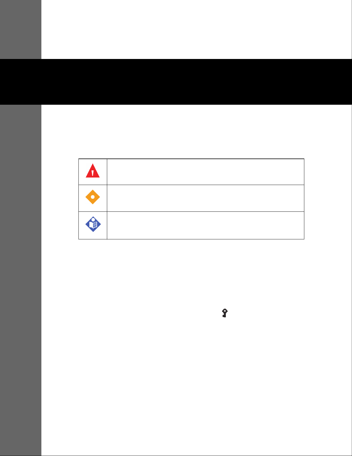
1.1 Definitions
This manual uses three indicators to highlight critical information: warning, caution, and note.
They are defined as follows:
WARNING
Indicates a condition that can endanger the patient or the ventilator operator.
Caution
Indicates a condition that can damage the equipment.
Note
Indicates points of particular emphasis, that make operation of the ventilator more efficient or convenient.
It is essential to read, understand and follow these instructions before using the Puritan Bennett™
560 ventilator.
In order to use the ventilator correctly and efficiently and to help prevent incidents, please pay
particular attention to section 1.2, Warnings, as well as all warnings and cautions contained
throughout this manual.
: Note:
Many ventilator functions are not accessible when the Locking key is enabled.
For additional assistance contact your clinician or equipment representative.
1.2 Warnings
1.2.1 General Warnings Regarding Use of Equipment
< WARNING:
The ventilator must be used only under the responsibility and on the prescription of a doctor.
1-1
Page 16

Safety Information
< WARNING:
The ventilator must be used according to its intended use. Refer to section 2.1, Indications for Use.
< WARNING:
Be aware this manual describes how to respond to the ventilator, but does not tell you how to respond
to the patient.
< WARNING:
While the ventilator is in use, an alternative means of ventilation should always be available in the event
of a ventilator problem. This is particularly true for ventilator-dependent patients. Supplementary
observation, appropriate for the patient’s condition, is also recommended.
< WARNING:
To ensure that ventilation continues uninterrupted, ensure alternative power sources are available (AC
power source, extra batteries, or an auxiliary DC car adapter). Be prepared for the possibility of power
failure by having an alternative means of ventilation ready for use—particularly for ventilatordependent patients.
< WARNING:
Do not allow a patient to remain connected to the ventilator when ventilation is stopped, because a
substantial quantity of exhalation gas, primarily carbon dioxide, may be inhaled by the patient. In some
circumstances, inhaling carbon dioxide may lead to under-ventilation, suffocation, and serious injury or
death.
< WARNING:
Always have immediate access to an alternative means of ventilation, which is ready for use, to avoid
patient death or serious injury.
< WARNING:
The ventilator must not be used with flammable anesthetic substances.
< WARNING:
Do not start ventilation until you ensure that the device is suitably assembled, that the air inlet filter is
properly installed and is not obstructed, and that there is proper clearance all around the unit. Also
ensure that the patient circuit is suitably connected to both the ventilator and the patient and that the
patient circuit, including all hoses, is not damaged or obstructed.
< WARNING:
A ventilator-dependent patient should always be monitored by trained and competent medical
personnel. Ensure that the patient’s caregiver is able and prepared to take suitable action in the event
the ventilator identifies an alarmed condition or experiences a problem.
< WARNING:
Do not use a patient circuit with a leak accessory for ventilator-dependent patients.
1-2 User Manual
Page 17

< WARNING:
Refer to this manual for equipment compatible with this ventilator. It may be unsafe to interconnect this
equipment with other equipment not described in this manual.
< WARNING:
Before dispensing the ventilator to caregivers or the patient for home use, ensure the Locking Key is
activated so that critical ventilator settings are not modified.
< WARNING:
Do not perform ventilator alarm tests while the patient is connected to the ventilator. Provide the
patient with an alternate means of ventilation before conducting these tests.
< WARNING:
Verify the functionality of the alarms before connecting the patient to the ventilator. Refer to Appendix
E, Alarms Tests.
Warnings
< WARNING:
If the ventilator fails the alarm tests or if you cannot complete the tests, refer to Chapter 3, Alarms and
Troubleshooting or call your equipment supplier or Covidien.
< WARNING:
When an alarm condition is triggered, or there is evidence of a patient-ventilator fault or problem,
examine the patient first before examining the ventilator.
< WARNING:
A continuous alarm condition will be activated if the ventilator power switch is turned off while
ventilation is in progress. When the power switch is turned back on again, ventilation will resume
without having to press the VENTILATION ON/OFF button.
< WARNING:
To reduce the risk of infection, wash your hands thoroughly before and after handling the ventilator or
its accessories.
< WARNING:
A patient treated by mechanical ventilation is highly vulnerable to the risks of infection. Dirty or
contaminated equipment is a potential source of infection. Clean the ventilator and its accessories
regularly and systematically before and after each use and following any maintenance procedure to
reduce the risks of infection. The use of a bacterial filter at the ventilator’s outlet (TO PATIENT) port—or
both ports if a double-limb circuit is used—is recommended. Refer to Chapter 7, Cleaning.
< WARNING:
Handle the ventilator with care during and after use, particularly when ambient temperatures are high.
Some ventilator surfaces may become hot, even if safety specifications are not exceeded.
User Manual 1-3
Page 18

Safety Information
< WARNING:
Do not connect the ventilator to any device other than a PC with a dedicated compatible Puritan
Bennett™ software package.
< WARNING:
The ventilator system is not intended to be a comprehensive monitoring device and does not activate
alarms for all types of conditions. For a detailed understanding of ventilator operations, be sure to
thoroughly read this manual before attempting to use the ventilator system.
1.2.2 Warnings Regarding Installation and Environment of Use
< WARNING:
Even though the Puritan Bennett™ 560 ventilator meets current safety standards, the internal Lithiumion battery of the device exceeds the 100Wh threshold and is therefore considered to be Dangerous
Goods (DG) Class 9 – Miscellaneous, when transported in commerce. As such, the Puritan Bennett™ 560
ventilator and/or the associated Lithium-ion battery are subject to strict transport conditions under the
Dangerous Goods Regulation for air transport (IATA: International Air Transport Association),
International Maritime Dangerous Goods code for sea and the European Agreement concerning the
International Carriage of Dangerous Goods by Road (ADR) for Europe. Private individuals who transport
the device are excluded from these regulations although for air transport some requirements apply. For
air transport; the Puritan Bennett™ 560 ventilator is permitted as checked-in or carry-on baggage. Two
spare batteries per person may be taken on board as carry-on luggage only, with the prior approval of
the airline. This classification and regulatory requirements may vary depending upon the country and
mode of transport. Therefore it is recommended that users verify with the carrier / airline as to which
measures to take before the voyage.
< WARNING:
To minimize the risk of damage, you must use the ventilator’s dual bag to transport the ventilator.
Ventilator accessories are listed in TableF-1.
< WARNING:
When using the ventilator in a carrying case, only use a carrying case that is listed in the instructions for
use to prevent adverse ventilator performance, which can consequently result in patient death.
< WARNING:
Regularly clean the ventilator’s dual bag according to manufacturer’s recommendations.
< WARNING:
The ventilator should never be immersed in any liquid, and any liquid on the surface of the device
should be wiped away immediately.
1-4 User Manual
Page 19

< WARNING:
To avoid damage to the ventilator, in particular the batteries or electrical components, fluids must not
be allowed to enter the device, particularly through the air inlet filter or the cooling apertures located
in the side, rear, and bottom panels of the ventilator.
< WARNING:
To ensure correct and lasting operation of the device, ensure that the ventilator is installed and
operated in the environmental conditions recommended in Appendix A, Specifications.
< WARNING:
Do not leave power cables lying on the ground where they may pose a hazard.
< WARNING:
Do not operate the ventilator in a magnetic resonance imaging (MRI) environment. Doing so could
cause a ventilator malfunction.
Warnings
< WARNING:
Do not operate the ventilator in the presence of active high frequency (HF) surgical equipment. Doing
so could cause a ventilator malfunction.
< WARNING:
Do not operate the ventilator in direct sunlight, near heat sources, outdoors, or near installations where
liquid may pose a risk without first providing adequate protection for the device.
< WARNING:
Avoid using the ventilator, if possible, in dusty environments. Dusty environments may require more
vigilant monitoring, cleaning, and/or replacement of air intake and other filters.
< WARNING:
Ensure that the ventilator’s immediate surroundings allow for the proper operational connection of the
device without folding, pinching, or damaging any of the required cables or tubes, and that the
connection of the patient circuit to the patient provides for a secure, comfortable fit.
< WARNING:
Ensure that the ventilator is not positioned or located such that the AC and DC connections at the back
of the ventilator are difficult to access.
< WARNING:
Do not cover the ventilator or place in a position that affects proper operation, e.g., blocking a front or
lateral opening.
User Manual 1-5
Page 20

Safety Information
< WARNING:
Place the ventilator in a safe place when ventilating and according to the recommendations in this
manual.
< WARNING:
Do not place the ventilator in a position where a child, pet or pest can reach it, or in any position that
might cause it to fall on the patient or someone else.
< WARNING:
To ensure correct and lasting operation of the ventilator, ensure that its air circulation holes (main inlet
or cooling) are never obstructed. Place the device in an area where air can freely circulate around the
ventilator and avoid installing it near floating fabrics, such as curtains.
< WARNING:
If the ventilator has been transported or stored at a temperature that differs more than ±20°C (±36°F)
from the temperature in which it will be operating, the ventilator should be allowed to stabilize in its
operating environment for at least 2 hours prior to use. When the ambient temperature is 20°C, 2 hours
are required to warm the ventilator from the minimum storage temperature or to cool the ventilator
from the maximum storage temperature prior to use.
< WARNING:
If the ambient temperature where the device is operated is greater than 35°C (95°F), the temperature of
the patient circuit or the flow supplied at the device outlet may exceed 41°C (106°F), and the patient
circuit may reach up to 60°C (140°F). This may lead to undesirable side effects for the patient. To avoid
injury to the patient move the patient and the ventilator to a cooler location. For more information,
contact Covidien.
< WARNING:
The default setting for altitude compensation is YES. Altitude compensation should always be set to YES
for accurate volume delivery calculations at all elevations.
< WARNING:
To reduce the risk of a fire hazard, keep matches, lighted cigarettes, and all other sources of ignition
(such as flammable anesthetics and/or heaters) away from the ventilator and oxygen hoses.
< WARNING:
Regularly check the cleanliness of the air inlet filter located on the rear of the ventilator. If necessary,
replace the filter before the recommended replacement period is over (see Chapter 8, Routine
Maintenance). This is particularly important when the ventilator is installed on a wheelchair, because
environmental conditions may cause the filter to become dirty more rapidly.
< WARNING:
Handle the ventilator with care during and after use, particularly when ambient temperatures are high.
Some ventilator surfaces may become hot, even if safety specifications are not exceeded.
1-6 User Manual
Page 21

< WARNING:
Exercise care to avoid any potential significant risks of reciprocal interference posed by the ventilator
and accessories during specific investigations or treatments.
1.2.3 Warnings Regarding Electrical Power Supplies
< WARNING:
The operator should connect the ventilator to an AC power source whenever available, for safer
operation.
< WARNING:
The maximum recommended shelf life of the internal battery is 2 years. Do not use a battery that has
been stored for 2 years prior to its first use.
< WARNING:
Periodic recharging is important to help maximize useful life of the battery. Do not store the internal
battery for extended periods, without recharging, as this may reduce the maximum life.
Warnings
< WARNING:
For the AC (“mains”) power cable to be properly secured, the attachment located on the power cable
must be fitted into the power cable holder incorporated in the battery access cover and located under
the AC (mains) power socket. Refer to section 4.2, Connecting to External AC Power.
< WARNING:
The power supply to which the ventilator is connected (both AC and DC) must comply with all
applicable standards and provide electrical power corresponding to the voltage characteristics
inscribed on the rear of the ventilator to ensure correct operation. Refer also to the electrical
specifications found in Appendix A, Specifications.
< WARNING:
Ensure that the ventilator’s internal battery is fully charged before connecting the ventilator to an
external DC power source. Powering the ventilator using an external 12–30 VDC power source (via the
DC power cable) does not enable its internal battery to recharge.
< WARNING:
Due to the internal battery’s limited reserve capacity, the ventilator should only be operated on the
internal battery when no other power source is available. Ensure that the internal battery never
becomes fully discharged.
< WARNING:
When using a car auxiliary adapter (cigarette lighter) ensure the car has been started prior to plugging
in the ventilator’s DC adapter. Refer to section 4.3, Connecting to an External DC Power Source.
User Manual 1-7
Page 22

Safety Information
< WARNING:
Even if the internal battery charging indicator is off, charging of the battery may sometimes be
incomplete if the ambient temperature is above 40°C (104°F) because of the battery’s internal heat
safety device.
< WARNING:
When the Low Battery alarm is triggered, immediately connect the ventilator to an AC power supply to
maintain ventilation and recharge the internal battery.
< WARNING:
Batteries should be disposed of according to environmental legislation in your country and locality.
< WARNING:
Never expose any batteries to direct flame.
< WARNING:
Ensure that the AC power cable is in perfect condition and not compressed. The device should not be
turned on if the AC power cable is damaged.
1.2.4 Warnings Regarding Hoses and Accessories
< WARNING:
The ventilator must not use, nor be connected to, any anti-static or electrically conductive hoses,
tubing, or conduits.
< WARNING:
Minimum and maximum VTE alarm parameters must be properly set to warn in the event of patient
disconnection.
< WARNING:
Before opening the packaging for the patient circuit, ensure that no damage is evident to the packaging
or its contents. Do not use if evidence of damage exists.
< WARNING:
The patient circuit should not be changed during ventilation.
< WARNING:
On a DAILY basis, inspect the patient circuit to ensure that it shows no signs of damage, is properly
connected, and is operating correctly without leakage.
< WARNING:
Single use accessories should not be reused.
1-8 User Manual
Page 23

< WARNING:
The exhalation block is intended for single use by a single patient . It may periodically be cleaned, but
it cannot be disinfected or sterilized. To maintain good measurement quality when used continuously,
clean the exhalation block periodically (refer to section 7.3, Cleaning the Exhalation Block). The
exhalation block should be changed every 4 months and cannot be reused with any other patient.
< WARNING:
During invasive ventilation (when an artificial airway bypasses the patient’s upper respiratory system),
the patient’s upper respiratory system cannot humidify the incoming gas. For this reason, a humidifier,
to minimize drying of the patient’s airway and subsequent irritation and discomfort, must be used.
< WARNING:
If exhaled tidal volume measurements are required to ensure correct patient ventilation a double-limb
patient circuit configuration must be used in order to detect leaks. In this case, both the minimum and
maximum VTE alarm parameters must be properly set to warn in the event of patient disconnection.
< WARNING:
Failing to replace a dirty air inlet filter or operating the ventilator without a filter may cause serious
damage to the ventilator.
Warnings
< WARNING:
Before cleaning the ventilator, first disconnect the ventilator and the patient circuit.
< WARNING:
If the ventilator is used indoors, the condition of the air inlet filter should be checked monthly. If the
ventilator is used outdoors or in a dusty environment, the filter should be checked weekly and replaced
as necessary.
< WARNING:
The air inlet filter is not reusable; do not attempt to wash, clean, or reuse it.
< WARNING:
The patient circuit should always be positioned to avoid hindering the patient's movements, to prevent
accidental disconnection or leakage, and to minimize the risk of patient strangulation.
< WARNING:
For pediatric use, ensure that the patient circuit type fits, and, in all respects, is suitable for use with a
child. Use a pediatric circuit for patients that weigh under 53 lb. (23 kg). To ensure proper performance
of the ventilator, use a recommended patient circuit; see TableF-2.
< WARNING:
Resistance of the exhalation valve and accessories (water traps, filters, HMEs, etc.) must be as low as
possible.
User Manual 1-9
Page 24

Safety Information
< WARNING:
Adding attachments to the ventilator breathing system can cause the pressure during exhalation at the
patient connection port to increase.
< WARNING:
The exhalation valve must allow rapid discharge of the circuit pressure. Ensure that the exhalation valve
is always clean and its evacuation aperture (exhaust port) is never obstructed.
< WARNING:
Users must always possess an additional breathing circuit and exhalation valve while using the Puritan
Bennett™ 560 ventilator.
< WARNING:
Always ensure that the humidification device is positioned lower than both the ventilator and the
patient. Use water traps, if necessary, to limit water in the patient circuit and periodically empty these
water traps. Take precautions when discarding the fluid in the water trap. Discard per local ordinance
for proper disposal.
< WARNING:
Use of a nebulizer or humidifier can lead to an increase in the resistance of inspiratory and exhalation
filters. Monitor the filters frequently for increased resistance or blockage.
< WARNING:
If a heated humidifier is used, you should always monitor the temperature of the gas delivered to the
patient. Gas delivered from the ventilator that becomes too hot may burn the patient's airway.
< WARNING:
Adding accessories to the ventilator breathing circuit, such as a humidifier and water trap(s), may result
in a decrease in tidal volume delivered to the patient due to the added compressible volume of the
accessory. Always assure that the patient is receiving the appropriate inspired volume when altering
the breathing circuit configuration.
< WARNING:
The level of inspiratory resistance of the circuit and accessories (bacteria filter, humidifier, HMEs, etc.)
must be as low as possible. Settings—particularly the Patient Disconnection alarm, maximum inspired
volume (Max VTI), and minimum inspired volume (Min VTI) settings—must be periodically adjusted
according to changes in the patient circuit resistance—especially when filters are replaced.
< WARNING:
To ensure proper performance of the ventilator, use a patient circuit recommended by Covidien in this
manual; refer to Chapter 4, Installation and Assembly and Appendix F, Parts and Accessories. The total
specified length of the patient circuit tubing as measured from the ventilator outlet to the ventilator
inlet is 1.1 meters (3.6 feet) to 2.0 meters (6.6 feet). The tubing must conform to all applicable standards
and must be fitted with Ø 22 mm terminals that also conform to all applicable standards. Ensure that
1-10 User Manual
Page 25

both the length and the internal volume of the patient circuit are appropriate for the tidal volume: a
corrugated tube of Ø 22 mm for adult patients, and a corrugated tube of Ø 15 mm for pediatric patients
with a tidal volume lower than 200 ml.
< WARNING:
To ensure proper performance of the ventilator, use only accessories (including oxygen accessories)
approved and recommended by Covidien. See Appendix F, Parts and Accessories or contact your
customer services.
< WARNING:
To reduce the likelihood of disconnection and to prevent adverse ventilator performance, use only
accessories compatible with the ventilator. Compatibility is determined by reviewing the instructions
for use of either the ventilator or the accessories.
< WARNING:
When using non-invasive ventilation (NIV) without an exhalation valve, use a vented nose or face mask
or a non vented combined with a leak accessory. When using non-invasive ventilation (NIV) with an
exhalation valve, use a non-vented mask.
Warnings
1.2.5 Warnings Regarding Settings
< WARNING:
Before starting ventilation, always verify that all settings are properly set in accordance with the
required prescription.
< WARNING:
Before starting ventilation, ensure that the device is properly assembled and that the air inlet, cooling
vents, and alarm sound diffusion holes are not obstructed. Ensure also that the patient circuit is of the
proper configuration (double or single limb), properly connected to the ventilator, and that the circuit
hoses are neither damaged nor compressed and contain no obstructions or foreign bodies.
< WARNING:
The CPAP mode does not provide a set respiratory rate. Do not use this mode for ventilator-dependent
patients.
< WARNING:
Do not allow a patient to remain connected to the ventilator when ventilation is stopped, because a
substantial quantity of exhalation gas, primarily carbon dioxide, may be inhaled by the patient.
< WARNING:
Alarm volume should be adjusted with respect to the ventilator’s operating environment and so that
the patient's caretakers can hear the alarms. The audible alarm vents located at the front of the device
should never be obstructed. The alarm can be paused with the Alarm Pause function by pressing the
ALARM CONTROL key twice once the alarm has been declared.
User Manual 1-11
Page 26

Safety Information
< WARNING:
Ensure that the I Sens setting is not set to OFF when ventilating patients capable of triggering
spontaneous breaths.
< WARNING:
The ventilator offers a variety of breath delivery options. Throughout the patient’s treatment, the
clinician should carefully select the ventilation mode and settings to use for that patient, based on
clinical judgment, the condition and needs of the patient, and the benefits, limitations, and
characteristics of the breath delivery options. As the patient’s condition changes over time, periodically
assess the chosen modes and settings to determine whether those are best for the patient’s current
needs.
< WARNING:
In adult or pediatric use ensure that the adjusted tidal volume is compatible with the needs of the
patient.
< WARNING:
When changing the mode during ventilation, significant transitions of pressure, flow or cycling rate
might occur, depending on the difference between the modes. Before setting the new mode, first
ensure that the settings between the different modes are compatible. This reduces the risk of
discomfort and harm to the patient.
< WARNING:
Do not conduct the ventilator alarm test while the patient is connected to the ventilator. Switch the
patient to an alternate means of ventilation before testing.
< WARNING:
The Min PIP alarm setting must be adjusted for the patient, but must also be set high enough to allow
the Patient Disconnection alarm to trigger properly. Perform the low pressure test to ensure the alarm
is properly set.
< WARNING:
The Max Leak alarm setting must be adjusted for the patient, but must also be set low enough to allow
the High Leakage alarm to trigger properly. Perform the max leak test to ensure the alarm is functioning
properly. This alarm only applies to leak configuration (NIV).
< WARNING:
If Apnea Time is set to a value higher than 60/Control R then the Apnea alarm will not activate.
< WARNING:
If an Apnea alarm is required, set the Apnea setting to YES in the Preferences Menu.
1-12 User Manual
Page 27

< WARNING:
The Apnea alarm should be set to YES for ventilator dependent patients.
< WARNING:
Setting any alarm limits to OFF or extreme high or low values can cause the associated alarm not to
activate during ventilation, which reduces its efficacy for monitoring the patient and alerting the
clinician to situations that may require intervention.
< WARNING:
Ensure the Insp Time setting is compatible with the physiological requirements of the patient.
< WARNING:
Adjustable alarms should not be systematically canceled; instead, they should be adjusted according to
the needs and condition of the patient.
< WARNING:
Do not pause, disable, or decrease the volume of the ventilator’s audible alarm if patient safety could
be compromised.
Warnings
< WARNING:
A continuous alarm condition will be activated if the ventilator power switch is turned off while
ventilation is in progress. When the power switch is turned back on again, the ventilation will resume
without having to press the VENTILATION ON/OFF button.
< WARNING:
In the SIMV mode the use of a double-limb circuit is recommended. The Min VTE setting should remain
active in the event that pressure losses are present on the patient circuit downstream from the proximal
pressure link. In such cases the Patient Disconnection alarm would not be systematically activated in
case of a disconnection of the circuit.
< WARNING:
The inspiration trigger threshold should be carefully modified in order to avoid the risk of false
triggering or “autotriggering” of the ventilator. For example, Level 0P, the most sensitive mode, is
recommended for pediatric use. However, for an adult, this setting may result in autotriggering.
< WARNING:
The sound level of the alarms should be adjusted according to the installation environment and the size
of the area monitored by the patient’s caregiver. Ensure that the alarm sound apertures at the front of
the device are never obstructed.
User Manual 1-13
Page 28

Safety Information
1.2.6 Warnings Regarding PC Connection and USB Memory Devices
< WARNING:
Do not connect the ventilator to any device other than a PC with a dedicated compatible Puritan
Bennett™ software package.
< WARNING:
Always verify the file ID before using a USB memory device to transfer data between the ventilator and
a PC.
< WARNING:
USB connections are not intended for connection to any devices other than the specified USB flash
storage (see section 5.2.1, USB Memory Device Specifications).
1.2.7 Warnings Regarding Maintenance
< WARNING:
Never use a ventilator or any components or accessories that appear to be damaged. If any signs of
damage are evident, contact your equipment supplier or Covidien.
< WARNING:
To ensure proper servicing and avoid the possibility of physical injury to personnel or damage to the
ventilator, only personnel authorized and qualified by Covidien should attempt to service or make
authorized modifications to the Puritan Bennett™ 560 ventilator.
< WARNING:
If you cannot determine the cause of a problem with your ventilator, contact your equipment supplier.
Do not use the ventilator until the problem has been corrected.
< WARNING:
To ensure proper performance of the ventilator, the preventative maintenance schedule should be
followed. For further information contact Covidien.
< WARNING:
On a daily basis, ensure the proper connection and operation of the patient circuit.
< WARNING:
If a problem with the ventilator is suspected, FIRST CHECK THAT THE PATIENT IS NOT IN DANGER. If
necessary, remove the patient from the ventilator and provide an alternative means of ventilation.
1-14 User Manual
Page 29

< WARNING:
After assembling, cleaning, or reassembling the patient circuit, and on a daily basis, inspect the hoses
and other components to ensure that there are no cracks or leaks and that all connections are secure.
< WARNING:
Use all cleaning solutions and products with caution. Read and follow the instructions associated with
the cleaning solutions you use to clean your ventilator. Use only those solutions listed in Table7-1.
< WARNING:
Never use a liquid cleaner inside the patient circuit, or on any component of a gas pathway. Clean the
patient circuit only as specified by the manufacturer's instructions.
< WARNING:
Do not attempt to open, repair or otherwise service the ventilator yourself. Doing so might endanger
the patient, damage the ventilator, or void your warranty. Only personnel authorized and qualified by
Covidien should repair, open or service the ventilator.
Warnings
< WARNING:
If the ventilator is damaged, or its external housing is not correctly closed, or it behaves in a way that is
not described in this manual (excessive noise, heat emission, unusual odor, alarms not triggered during
the start-up procedure), the oxygen and power supplies should be disconnected and use of the device
stopped immediately.
< WARNING:
The exhalation block is intended for single use by a single patient . It may periodically be cleaned, but
it cannot be disinfected or sterilized. To maintain good measurement quality when used continuously,
clean the exhalation block periodically (refer to section 7.3, Cleaning the Exhalation Block). The
exhalation block should be changed every 4 months and cannot be reused with any other patient.
< WARNING:
Ensure that the exhalation block is completely dried after cleaning and prior to use.
< WARNING:
When an exhalation block is set up, each time it is removed, or after installing a new exhalation block on
the machine, it is essential that the exhalation flow sensor be recalibrated before the exhalation block
is used. Refer to section 8.3, Calibrating the Exhalation Flow Sensor.
< WARNING:
The patient circuit is intended for single use by a single patient and should be changed according to
the manufacturer’s recommendations and according to the patient circuit lifetime. Refer to the
instructions for use supplied by the manufacturer of the patient circuit (included with the ventilator)
and Chapter 4, Installation and Assembly.
User Manual 1-15
Page 30

Safety Information
< WARNING:
A patient treated by mechanical ventilation is highly vulnerable to the risks of infection. Dirty or
contaminated equipment is a potential source of infection. Clean the ventilator and its accessories
regularly and systematically before and after each use and following any maintenance procedure to
reduce the risks of infection. The use of a bacterial filter at the ventilator’s outlet (TO PATIENT) port—or
both ports if a double-limb circuit is used—is recommended. Refer to Chapter 7, Cleaning.
< WARNING:
Regularly check the cleanliness of the air inlet filter located on the rear of the ventilator. If necessary,
replace the filter before the recommended replacement period is over (see Chapter 8, Routine
Maintenance). This is particularly important when the ventilator is installed on a wheelchair, because
environmental conditions may cause the filter to become dirty more rapidly.
< WARNING:
For environmental protection, the ventilator and its components, whatever their respective conditions
of operation, cannot be disposed of with household waste and must be submitted for suitable selective
collection and possible recycling. Observe all applicable regulations when disposing of the ventilator
and any of its components.
< WARNING:
Before using the ventilator’s internal battery, ensure that the battery is fully charged and that the
charge holds. Back up ventilators or those in storage should be connected to an AC power source to
protect the integrity of the battery.
< WARNING:
The maximum recommended shelf life of the internal battery is 2 years. Do not use a battery that has
been stored for 2 years prior to its first use. Periodic recharging is important to help maximize useful life
of the battery. Do not store the internal battery for extended periods, without recharging, as this may
reduce the maximum life.
< WARNING:
To connect the ventilator to an external power source, first ensure the ventilator’s I/O (power) switch is
off (O). Then, connect the desired power cable to the ventilator. Finally, connect the power cable to the
external power source.
< WARNING:
To disconnect the ventilator from an external power source, first power down the ventilator. Then,
disconnect the power cable from the external power source and, finally, the ventilator.
< WARNING:
Connect the external DC power source by first connecting the power cable to the ventilator and then to
the external DC source. Follow the reverse procedure to disconnect the device from the external DC
power source.
1-16 User Manual
Page 31

< WARNING:
Connect the external electrical power source by first connecting the power cable to the ventilator and
then to the external power source. Follow the reverse procedure to disconnect the device from
electrical power sources.
1.2.8 Warnings Regarding Oxygen
< WARNING:
The ventilator must not be used with flammable anesthetic substances.
< WARNING:
Oxygen therapy for patients with respiratory failure is a common and effective medical prescription.
However, be aware that inappropriate oxygen use may potentially lead to serious complications,
including, but not limited to, patient injury.
Warnings
< WARNING:
Strictly follow the instructions provided in section 4.8.2, Connecting the Oxygen Supply, which include
the use of a flow regulator and special oxygen connector.
< WARNING:
To avoid injury to the patient and/or possible damage to the ventilator: before connecting the
ventilator to the oxygen supply, ensure a flow meter (flow regulator) is connected to the ventilator to
regulate the oxygen supply to the required specification.
< WARNING:
The Puritan Bennett™ 560 ventilator can be used with an optional oxygen analyzer with minimum and
maximum concentration alarms. Always measure the delivered oxygen with a calibrated oxygen
analyzer (FiO
the prescribed oxygen concentration is delivered to the patient.
< WARNING:
The Puritan Bennett™ 560 ventilator is designed to deliver a percentage of oxygen equal or lower than
50%. Do not exceed this value as this may cause the ventilator to malfunction and put the patient at risk.
< WARNING:
Ensure that the oxygen supply pressure to the machine never exceeds 7 psi (50 kPa) or a flow of 15 lpm.
For volume and sensitivity tolerances, refer to TableA-7.
kit) that features a minimum and maximum concentration alarm in order to ensure that
2
< WARNING:
In the event of an oxygen leak, shut down the supply of oxygen at its source. In addition, remove and/
or keep any incandescent source away from the device, which may be enriched with oxygen. Circulate
fresh air into the room to bring the oxygen level down to normal.
User Manual 1-17
Page 32

Safety Information
< WARNING:
The hose connecting the ventilator to the oxygen source must be designed exclusively for use with
medical-grade oxygen. Under no circumstances should the oxygen hose be modified by the user. In
addition, the hose must be installed without the use of lubricants.
< WARNING:
Ensure that the only gas supplied to the ventilator through the dedicated oxygen supply connector is
medical-grade oxygen.
< WARNING:
The coupler must not remain connected to the oxygen inlet unless it is also connected to a leakproof,
external oxygen gas source. When an oxygen supply is not being used with the ventilator, disconnect
the oxygen source completely from the ventilator.
< WARNING:
To prevent any interference with the internal sensors of the ventilator, do not install a humidifier
upstream of the ventilator.
< WARNING:
To ensure stability, when the Puritan Bennett™ 560 ventilator is mounted on a cart, the weight of the
oxygen bottle should not exceed 14 kg (30 lbs).
< WARNING:
The oxygen supply hose ages even when it is not in use and should be replaced periodically. Follow the
expiration date, if any.
< WARNING:
The oxygen supply must be regulated using a flow meter connected to the source gas outlet.
< WARNING:
The oxygen supply must be shut off when ventilation is interrupted. Before disconnecting the oxygen
hose, allow the ventilator to continue for a few cycles without oxygen to flush the patient circuit of
excess oxygen.
< WARNING:
Before connecting the oxygen supply, ensure that the stud on the oxygen inlet is protruding outwards.
< WARNING:
Inspect the oxygen coupler before use to ensure it has its black O-ring attached and in good condition.
Do not use an oxygen coupler with a missing, damaged, or worn O-ring.
1-18 User Manual
Page 33

1.2.9 Warnings Regarding Electromagnetic Interference
< WARNING:
The Puritan Bennett™ 560 ventilator requires special precautions for electromagnetic compatibility and
should be installed and started according to the recommendations found in Appendix A, Specifications.
In particular, the use of nearby mobile and portable communications equipment using radio
frequencies, such as mobile telephones or other systems exceeding the levels set in the IEC 60601-1-2
standard, may affect its operation. Refer to section A.10, Manufacturer’s Declaration.
< WARNING:
Portable RF communications equipment (including peripherals such as antenna cables and external
antennas) should be used no closer than 30 cm (12 inches) to any part of the ventilator, including cables
specified by the manufacturer. Otherwise, degradation of the performance of this equipment could
result.
< WARNING:
The use of any accessory other than those specified, with the exception of the power supplies or cables
sold by Covidien, may lead to an increase in electromagnetic emissions or a decrease in the equipment
protection against electromagnetic emissions. If the ventilator is used adjacent to such accessories or
stacked with such devices, the ventilator’s performance should be monitored to verify normal
operation.
Symbols and Markings
1.3 Symbols and Markings
Symbols Descriptions
It is essential to read, understand, and follow these instructions before using the Puritan Bennett™ 560 ventilator (ISO 7000-0434A).
This symbol appears on the ventilator’s back panel, see item 5 in Table1-2.
It is mandatory to read, understand, and follow these instructions before using the Puritan Bennett™ 560 Ventilator (ISO 7010-M002). This symbol appears on the ventilator’s air inlet label, see item 5 in Table1-2.
Type BF applied part (IEC 60417-5333).
A regulatory standard classification for protection against electrical shock for the part of the device that contacts the patient.
This symbol appears on the ventilator’s back panel; see item 5 in Table1-2.
Direct current, DC (IEC 60417-5031).
This symbol appears on the ventilator’s front panel and back panel; see Figure 1-1, and item 9 in Figure 1-3.
Alternating current, AC (IEC 60417-5032).
This symbol appears on the ventilator’s front panel and back panel; see item 8 in Figure 1-3, and item 10 in
Figure 2-3 (page 2-7).
Internal battery.
This symbol appears on the ventilator’s front panel; see item 10 in Figure 2-3 (page 2-7).
Table1-1.Ventilator Symbols
User Manual 1-19
Page 34

Safety Information
Table1-1.Ventilator Symbols (Continued)
Symbols Descriptions
Insulation class II equipment (IEC 60417-5172).
A regulatory standard classification for protection against electric shock. Class II equipment relies on double
insulation rather than protective earthing.
This symbol appears on the ventilator’s back panel; see item 5 in Table1-2.
Index of Protection rating for the ventilator’s enclosure, defined in IEC 60529 (BSEN60529).
The first digit, 3, indicates protection against the intrusion of small foreign bodies (including fingers, tools,
wires, etc. with a diameter greater than 2.5 mm) into the ventilator. The second digit, 2, indicates protection
against water dripping or falling vertically when the enclosure is tilted at an angle up to 15° from its normal
position, as well as an environment featuring water vapor condensation and/or light rain.
This rating appears on the ventilator’s back panel; see item 5 in Table1-2.
CSA—Canadian Standards Association.
This symbol appears on the ventilator’s back panel; see item 5 in Table1-2.
CE—Conformity European
Signifies compliance with the medical device directive 93/42/EEC as amended by 2007/47/EC.
This symbol appears on the ventilator’s back panel; see item 5 in Table1-2.
This combined symbol appears on the ventilator’s UP/UNFREEZE key; see item 4 in Figure 2-3 (page 2-7).
This key is used to: move the LCD display’s cursor upwards, line-by-line; increase the value of displayed and
selected parameter settings; restart (“unfreeze”) waveforms tracing.
This combined symbol appears on the ventilator’s DOWN/FREEZE key; see item 6 in Figure 2-3 (page 2-7).
This key is used to: move the LCD display’s cursor downwards, line-by-line; decrease the value of displayed
and selected parameter settings; stop (“freeze”) waveforms tracing.
This symbol appears on the ventilator’s ENTER key; see item 5 in Figure 2-3 (page 2-7).
This key is used to confirm command actions.
This combined symbol appears on the ventilator’s ALARM CONTROL key; see item 2 in Figure 2-3 (page 2-7).
This key is used to: cancel the audible portion of alarms for 60 seconds at a time; cancel an alarm.
For more information, see Appendix E, Alarms Tests.
This symbol appears on the ventilator’s MENU key; see item 7 in Figure 2-3 (page 2-7).
This key is used to access the ventilator’s menus via the ventilator’s front panel LCD display.
This symbol (IEC 60417–5009) appears on the ventilator’s VENTILATION ON/OFF button; see item 8 in Figure
2-3 (page 2-7).
This button is used to start and stop ventilation.
TO PATIENT port.
This symbol appears on the front right of the ventilator, adjacent to the TO PATIENT port; see item 1 in Fig-
ure1-1.
FROM PATIENT port (double-limb option).
This symbol appears on the front left of the ventilator, adjacent to the FROM PATIENT port; see item 4 in Fig-
ure1-1.
Patient proximal pressure port.
This symbol appears on the front right of the ventilator, adjacent to the proximal pressure and TO PATIENT
ports; see Figure 1-1, and item 3 in Figure1-4.
1-20 User Manual
Page 35

Symbols Descriptions
Exhalation valve pilot port.
This symbol appears on the front right of the ventilator, adjacent to the exhalation valve and TO PATIENT
ports, indicating the connection of the tubing between the patient circuit exhalation valve; see Figure 1-1,
and item 3 in Figure1-4.
Oxygen inlet.
This marking appears on the back panel of the ventilator, adjacent to the oxygen inlet port; see item 2 in Fig-
ure1-3.
Nurse call connection.
This symbol appears on the back panel of the ventilator, adjacent to the nurse call receptacle; see item 12 in
Figure1-3.
Note: Nurse call is not intended for use in the home environment.
Switch in “Off” position (IEC 60417-5008).
This symbol appears on the I/O (power on/off) switch on the back panel of the ventilator to indicate the
switch’s “Off” position. See item 2 in Figure 2-2 (page 2-6).
Switch in “On” position (IEC 60417-5007).
This symbol appears on the I/O (power on/off) switch on the back panel of the ventilator to indicate the
switch’s “On” position. See item 2 in Figure 2-2 (page 2-6).
Symbols and Markings
Table1-1.Ventilator Symbols (Continued)
Software lock enabled.
This symbol appears at upper left in the ventilator’s LCD display when the keyboard Locking key is enabled.
Internal battery.
This symbol appears at top center in the ventilator’s LCD display to indicate that the ventilator is being
powered by its internal battery. See item 1 in Figure 2-4 (page 2-8), and Chapter 6, Internal Battery, for more
information.
Pressure rise times (inspiratory phase) parameter.
These symbols appear on the ventilation mode menu screens. In pressure ventilation modes, you can select
one of four rise times with setting 1 representing the fastest rise time and setting 4 representing the slowest.
Flow shape (“flow distribution shape”, inspiratory phase) parameter.
These symbols appear on the ventilation mode menu screens; selectable for V A/C mode only. In volume ventilation mode you can select between Square (SQ), Descending (D) or Sinusoidal (S) flow patterns.
Selected line (filled square).
When making menu choices, this graphic indicates the line on which the cursor is currently positioned.
Non-selected line (empty square).
When making menu choices, this graphic indicates a line on which the cursor is currently not positioned.
Locked parameter line.
When making menu choices, this graphic indicates a line that cannot be selected (the Locking key is enabled).
Active parameter line.
When making menu choices, this graphic indicates that the current parameter is selected and can be
changed. See Chapter 5, Operating Procedures.
User Manual 1-21
Page 36

Safety Information
Table1-1.Ventilator Symbols (Continued)
Symbols Descriptions
Inspiratory effort detected.
This symbol appears in the front panel display’s Status window when the patient triggers a breath.
Parameter adjustment bar.
This graphic shows the current setting for parameters such as display contrast and alarm volume in the Preferences menu.
WEEE (Waste Electrical and Electronic Equipment).
This symbol means that this product must not be disposed of with household waste. Observe local ordinances for proper disposal. See item 5 in Table1-2.
Year of manufacture.
Manufacturer.
Authorized representative.
Audio paused (ALARM CONTROL key pressed once).
This symbol means the sounding of audible alarms is currently disabled. This period lasts 60 seconds. For
more information, see section 3.5, Pausing the Audible Portion of Alarms.
Alarm paused (ALARM CONTROL key pressed twice).
This symbol means one or more alarms have been paused, or reset/canceled. The alarm is paused until the
alarm condition is corrected and the condition reoccurs. For more information, see section 3.6, Pausing and
Resetting Alarms.
Alarm off (Apnea off).
This symbol means that the Apnea alarm has been set to OFF in the Preferences menu. For more information,
see section 3.6, Pausing and Resetting Alarms.
Exhalation valve detected.
This symbol means that an exhalation valve has been detected during ventilation.
No exhalation valve detected.
This symbol means that no exhalation valve has been detected during ventilation.
Single patient use only (ISO 7000-1051).
This symbol means that the labeled device is for use by a single patient only.
Freeze waveforms.
This symbol means the tracing of patient pressure and flow waveforms is currently paused or “frozen.”
Follow instructions for use (ISO 7000-1641).
This symbol directs the user to observe and adhere to the instructions contained in the product’s user manuals.
USB port.
This symbol indicates a communications port for interfacing with a USB connector. See item 11 in Figure1-3.
1-22 User Manual
Page 37

Symbols Descriptions
PC connection.
This symbol indicates a port that can be used by authorized Covidien product service personnel or Covidien
service personnel for software maintenance. See item 10 in Figure1-3.
Atmospheric pressure limitations. See section A.7 for specifications.
Humidity limitations. See section A.7 for specifications.
Temperature limitations. See section A.7 for specifications.
Fragile.
Symbols and Markings
Table1-1.Ventilator Symbols (Continued)
Keep dry.
Keep away from direct sunlight.
This side up.
Stacking limitation.
The number shown (represented by “n”) indicates the maximum number of additional identical packages
that may be stacked on top of a package containing this device, when this device is correctly packaged.
For the Puritan Bennett™ 560 ventilator, n = 2.
Lithium battery.
This symbol Indicates that the contents of the package contain lithium batteries.
User Manual 1-23
Page 38

Safety Information
Labels (Identification and Instruction Information)
1.4
Various labels or specific markings are affixed to the ventilator that describe precautions to be taken
for the correct use of the ventilator and contribute to the traceability of the product. See Table 1-2
and the figures on the following pages for illustrations of these labels and markings and their locations on the ventilator. Use the item numbers in Table 1-2 to locate the labels in Figures 1-1 through
1-4.
Table1-2.Ventilator Labels and Markings
1. TO PATIENT port label
(Figures 1-1 and 1-4)
5. Air inlet label
(Figure 1-3)
1—Location of DC power cable
receptacle
2. Oxygen inlet marking and label
(Figure 1-3)
6. Exhaled gas outlet label
(Figure 1-2)
3. Exhalation valve and patient
pressure connection label
(Figures 1-1 and 1-4)
7. Identification label
(Figure 1-4)
4. FROM PATIENT port, exhala-
tion limb connection of patient
circuit—single use exhalation
block label
(Figures 1-1, 1-2, and 1-4)
1—Location of AC power cable
receptacle
8. AC power (mains) cable
receptacle marking
(Figure 1-3)
9. External DC cable receptacle
marking
(Figure 1-3)
label
13. FiO
2
(Figures 1-1 and 1-4)
1-24 User Manual
10. PC connection marking
(Figure 1-3)
11. USB port marking
(Figure 1-3)
12. Nurse call cable receptacle
marking
(Figure 1-3)
Page 39

: Note:
The item number callouts in the following figures correspond to those listed in Table1-2.
Labels (Identification and Instruction Information)
Figure1-1.Locations of Labels—Top-Front View
Figure1-2.Locations of Labels—Front-Left View
User Manual 1-25
Page 40

Safety Information
Figure1-3.Location of Labels and Markings—Rear View
Figure1-4.Location of Labels—Bottom View
1-26 User Manual
Page 41

2 Ventilator Overview
2.1 Indications for Use
The Puritan Bennett™ 560 Ventilator is indicated for the continuous or intermittent mechanical
ventilatory support of patients weighing at least 11 lb (5 kg) who require mechanical ventilation.
The ventilator is a restricted medical device intended for use by qualified, trained personnel under
the direction of a doctor. It is essential to read, understand, and follow these instructions before
using the Puritan Bennett™ 560 Ventilator.
2.1.1 Target Patients
Specifically, the ventilator is applicable for adult and pediatric patients who require the following
general types of invasive or non-invasive ventilatory support, as prescribed by an attending
doctor:
• Positive Pressure ventilation
• Assist/Control, SIMV, or CPAP modes of ventilation
• Breath types including Volume Control, Pressure Control, and Pressure Support
2.1.2 Target Environments
The ventilator is suitable for use in institutional, home, and portable settings. It is not intended for
use in Emergency Medical Service (EMS) such as an emergency transport.
The Puritan Bennett™ 560 Ventilator is suitable for use on commercial aircraft, per FAA requirements. See section A.11, Standards Compliance and IEC Classification. Patients traveling with the
Puritan Bennett™ 560 Ventilator may be required by their airline to demonstrate evidence of compliance with the RTCA/DO-160F standard, as well as other requirements. Contact your airline prior
to travel to determine airline specific requirements and documentation.
< WARNING:
Even though the Puritan Bennett™ 560 Ventilator meets current safety standards, the internal
Lithium-ion battery of the device exceeds the 100Wh threshold and is therefore considered to be
Dangerous Goods (DG) Class 9 – Miscellaneous, when transported in commerce. As such, the Puritan
Bennett™ 560 Ventilator and/or the associated Lithium-ion battery are subject to strict transport
conditions under the Dangerous Goods Regulation for air transport (IATA: International Air Transport
2-1
Page 42

Ventilator Overview
Association), International Maritime Dangerous Goods code for sea and the European Agreement
concerning the International Carriage of Dangerous Goods by Road (ADR) for Europe. Private
individuals who transport the device are excluded from these regulations although for air transport
some requirements apply. For air transport; the Puritan Bennett™ 560 Ventilator is permitted as
checked-in or carry-on baggage. Two spare batteries per person may be taken on board as carry-on
luggage only, with the prior approval of the airline. This classification and regulatory requirements may
vary depending upon the country and mode of transport. Therefore it is recommended that users verify
with the carrier / airline as to which measures to take before the voyage.
2.1.3 Target Operators
< WARNING:
This ventilator must be used only under the responsibility and on the prescription of a doctor.
The ventilator may be operated by the following caregivers:
• Respiratory therapists
• Doctors
• Nurses
• Homecare providers
• Patient and patient’s families
For more details on knowledge and skill requirements for operating the Puritan Bennett™ 560 ventilator, please consult your clinician.
It is the responsibility of the clinician or clinical educator to ensure that both the patient and the
caregiver fully understand the topics necessary for operation of the ventilator.
2.2 Contraindications
This ventilator is not for use with anesthetic gases, and is not intended for use as an emergency
transport ventilator.
2-2 User Manual
Page 43

Operational Use
Operational Use
2.3
The Puritan Bennett™ 560 ventilator uses a micro-turbine to provide ventilatory support to patients.
Clinicians may use a variety of interfaces to connect patients to the ventilator for continuous or
intermittent ventilatory support. Some examples include mouthpieces; nasal masks or full face
masks; endotracheal tubes or tracheotomy tubes. User-selectable ventilation modes are:
• Assisted Controlled Volume (V A/C)
• Assisted Controlled Pressure (P A/C)
• Volume Synchronized Intermittent Mandatory Ventilation (V SIMV)
• Pressure Synchronized Intermittent Mandatory Ventilation (P SIMV)
• Continuous Positive Airway Pressure (CPAP)
• Pressure Support Ventilation with apnea ventilation (PSV/ST)
2.3.1 Safety Net
Incorporated in the ventilator design is an alarm system that continuously monitors both patient
and machine for signs of specific errors or faults that could lead to an unsafe condition. Should any
of these errors or faults be detected, the alarm system announces the specific alarm condition both
audibly and visually. The machine-related alarm conditions are factory set, whereas the patientrelated alarm conditions are defined by alarm-threshold values selected by an operator (a clinician
or a caregiver). For more information, see Chapter 3, Alarms and Troubleshooting.
2.3.2 Settings
A software key, known as the Locking key, restricts access to ventilation parameter settings and ventilation mode changes in order to distinguish between clinician usage and patient usage.
2.3.3 Oxygen Enrichment
Oxygen may be supplied from an external, low pressure source, but the oxygen flow must be
limited to 15 lpm (50 kPa, 500 mbar). The ventilator automatically compensates for the extra flow
created by the external oxygen supply (see Chapter 4, Installation and Assembly.)
2.3.4 Breathing Circuit
The ventilator can be used with a single- or double-limb patient circuit. If exhaled volume monitoring is required (such as ventilator dependent patients), use the double-limb circuit for exhaled tidal
volume monitoring. For more information, see section 4.4, Patient Circuit.
User Manual 2-3
Page 44

Ventilator Overview
< WARNING:
Users must always possess an additional breathing circuit and exhalation valve while using the Puritan
Bennett™ 560 ventilator.
2.4 Device Classification
The ventilator’s IEC/EN 60601-1classification is as follows:
• Protection/insulation class (electric shock): Class II
• Protection index of enclosure: IP32
• Degree of protection against risk of electric shock: BF
• Power: External (AC–mains, or DC–cigarette lighter) or internal (DC–battery)
• Operation mode: Continuous operation
For additional information, see Appendix A, Specifications.
2-4 User Manual
Page 45

Front Panel
2.5
Front Panel
Figure2-1.Front Panel
1 LCD display—Shows information about the ventilator, including
patient hours and software version, ventilation modes and settings,
and monitored and calculated patient data and waveforms. The
display also allows the user to view and, using the control panel,
adjust the ventilator’s operating and alarm configuration settings.
2 Control panel—Features the controls for setting up and operat-
ing the ventilator, and LEDs to indicate the ventilator's power
source, ventilation on/off status, and alarm priority level. Control
functions include turning on and off the ventilation, configuring
ventilation modes, pausing audible alarms, canceling alarms, and
setting device and alarm parameters.
3
FiO
sensor connection—Connection for FiO2 sensor, which mon-
2
itors the amount of oxygen in the patient circuit.
4 Patient connection port—Provides an outlet for the gas to be
delivered to the patient via the patient circuit.
5 Patient pressure monitoring port—Nipple for monitoring proxi-
mal patient pressure.
1. If exhaled tidal volume monitoring is required, use the double-limb circuit.
6 Exhalation valve port—Nipple for providing piloting
pressure to the exhalation valve. Controls the open-closed
position of the exhalation valve.
7
Lateral and front openings—Vents that allow for air cir-
culation to cool the ventilator’s internal components. In
addition, these openings function as sound ports for
audible alarms.
WARNING: Do not cover or obstruct these openings.
8 From patient port—Exhaled volume measurements are
taken from this port, through which a portion of the
exhaled gas is diverted to the exhalation flow sensor.
VTE is calculated from this flow measurement.
9 Exhaled gas outlet—Exhalation valve connects here.
1
User Manual 2-5
Page 46

Ventilator Overview
Back Panel
2.6
Figure2-2.Back Panel
1 Ergonomic carrying handle. 7 PC cable connector:
USB mini-B connector used for Puritan Bennett™ ventilator
test software.
WARNING: Do not connect the ventilator to any device other
than a PC with a dedicated compatible Puritan Bennett™ software package.
2 I/O (power) switch with protective cover:
Device powered on in position I; device switched off in position 0.
3 AC power (mains) cable connector. 9 Nurse call output connector:
4 AC power (mains) cable holding system:
Secures AC power cable to avoid accidental disconnection.
5 Access cover for the internal battery. 11 Air inlet filter:
6 DC power cable connector with key.
8 O2 inlet port:
Connects the ventilator to a low pressure oxygen source via an
adapter connected to the O
Used to connect the ventilator to the nurse call system.
Note: Nurse call is not intended for use in the home environment.
10 USB memory device connection:
USB connection to be used with the Puritan Bennett™ Respiratory Insight software package. There are two USB type A ports.
WARNING: USB connections are not intended for connection
to any devices other than the specified USB flash storage (per
section 5.2.1, USB Memory Device Specifications).
Filters air as it enters the ventilator.
inlet (see section 4.8, Oxygen).
2
2-6 User Manual
Page 47

Control Panel
2.7
Control Panel
Figure2-3.Control Panel
1 Alarm indicators (two LEDs):
Red indicator:
• Continuous: Very high priority (VHP) alarm activated.
• Flashing: High priority (HP) alarm activated.
Yellow indicator:
• Flashing: Medium priority (MP) alarm activated.
• Continuous: Low priority (LP) alarm activated.
2 ALARM CONTROL key:
• Press once to pause an audible alarm for 60 seconds.
• Press twice to halt visual and audible alarms. If alarm is remedied, the alarm is canceled (other than the high pressure alarm).
3 Display screen:
Shows modes, ventilation settings, patient data and waveforms,
configuration of the ventilator, and alarm management.
4 UP/UNFREEZE key:
• Moves the cursor up and increases parameter values.
• During ventilation, reactivates waveform tracing in the Waveform menu.
5 ENTER key:
• Access to a setting value and validation of the modification of
this setting.
• Access to a sub-menu.
6 DOWN/FREEZE key:
• Moves the cursor down and decreases parameter values.
• During ventilation, freezes the waveform shown in the Waveform menu.
7 MENU key:
Changes the menu shown. From the Ventilation menu screen,
press this key to show the Alarm menu screen.
When a USB memory device is inserted into the ventilator,
press this key to show the USB memory device screen.
8 VENTILATION ON/OFF button:
• ON: Press briefly and release to start ventilation.
• OFF: Press and hold for 3 seconds, then press again to stop
ventilation.
9 Ventilation status indicator:
• Blue indicator illuminated: Device is turned on and ventilation
is off (on standby).
• Blue indicator off: Ventilation is on.
10 Electrical power source indicators:
• AC power indicator lit: AC power source connected.
• DC power indicator lit: DC power source connected.
• Internal battery indicator lit continuously: Internal battery in
use (no external power source connected.)
• Internal battery indicator flashing: Battery charging.
User Manual 2-7
Page 48

Ventilator Overview
Ventilation Menu
2.8
Figure2-4.Ventilation Menu Display (on standby at left; during ventilation at right)
1 General information line:
Shows the current ventilation mode,
along with the following:
: Battery symbol if the ventilator is
powered by the internal battery.
: Audio paused symbol if an alarm is
currently inhibited.
: Alarm paused symbol if an alarm
has been canceled manually and the
cause of the alarm remains.
: Apnea alarm deactivation symbol.
: Exhalation valve symbol.
: No exhalation valve symbol.
ABS: Absolute symbol.
REL: Relative symbol.
4 Bargraph:
Shows pressure generation during ventilation.
2 Ventilation settings:
Shows the specific ventilation parameter
values for the currently selected ventilation
mode.
5 Status/monitored data window:
• Ventilation stopped (standby): Shows the
message, “PRESS TO START VENTILATION.”
• Ventilation on: Parameters are monitored
and shown.
• The Inspiratory effort detected symbol
appears adjacent to the monitored I:E ratio
when the patient actively triggers a breath.
3 Preferences menu access line:
Highlight this line and press the
ENTER key to show the Preferences
menu.
Alarm conditions window:
6
• For active alarms, scrolls through active
alarm messages in flashing reverse video.
• For inactive alarms, shows the last alarm
along with its trigger date and end-ofevent time.
See Chapter 3, Alarms and Troubleshooting
for details.
2-8 User Manual
Page 49

Alarm Menu
2.9
Alarm Menu
Figure2-5.Alarm Menu (on standby at left; during ventilation at right)
1 Title line:
Shows ventilation mode and the following symbols:
: Battery symbol if the ventilator is
powered by the internal battery.
: Audio paused symbol if an alarm is
currently inhibited.
: Alarm paused symbol if an alarm has
been canceled manually and the cause of
the alarm remains.
: Apnea alarm deactivation symbol.
: Exhalation valve symbol.
: No exhalation valve symbol.
4 Status/monitored data window:
• Ventilation stopped (standby): Shows
the message, “PRESS TO START VENTILATION.”
• Ventilation on: Parameters are monitored and shown.
• The Inspiratory effort detected
symbol appears adjacent to the monitored I:E ratio when the patient actively
triggers a breath.
2 Alarm settings:
Shows the specific alarm parameter
values for the currently selected ventilation mode, which are:
• Minimum and maximum alarm threshold settings
• Current monitored patient readings, or
hyphen (–) when ventilation is in standby
5 Alarm message window:
• For active alarms, scrolls through active alarm messages in flashing reverse video.
• For inactive alarms, shows the last alarm along with its trigger date and end-of-event
time.
See Chapter 3, Alarms and Troubleshooting for details.
3 Access line to Alarm Logs menu.
Highlight this line and press the ENTER
key to show the Alarm Logs menu.
See section 3.4, Alarm Logs Menu.
User Manual 2-9
Page 50

Ventilator Overview
Waveforms Menu
2.10
The display of waveforms (see Figure 2-6) is optional and can be selected using the Menu key.
The Waveform menu is only accessible when ventilation is active.
Figure2-6.Waveforms Menu
1 Title line:
Shows ventilation mode and the following symbols:
: Battery symbol if the ventilator is
powered by the internal battery.
: Audio paused symbol if an alarm is
currently inhibited.
: Alarm paused symbol if an alarm has
been canceled manually and the cause of
the alarm remains.
: Apnea alarm deactivation symbol.
: Freeze waveforms symbol if the
tracing of patient waveforms has been
halted during ventilation.
: Exhalation valve symbol.
: No exhalation valve symbol.
2 Graphic zone:
Shows the patient’s pressure and flow
waveforms as a function of time.
3 Numeric zone:
Shows monitored data.
2-10 User Manual
Page 51

USB Memory Device Menu
2.11
1 Title line 3 USB Memory Device menu
2 Ventilator serial number 4 Dialogue box
USB Memory Device Menu
Figure2-7.USB Memory Device Menu
2.12
If Ventilator Failure Occurs
If a problem with the ventilator is suspected, first check that the patient is not in danger. If necessary, remove the patient from the ventilator and provide an alternate means of ventilation.
Keep in mind that troubleshooting information is available in this manual to assist you in the event
of a problem. See Chapter 3, Alarms and Troubleshooting.
If you cannot determine the cause of a problem, contact your equipment supplier or Covidien. See
section 8.7, Service Assistance.
User Manual 2-11
Page 52

Ventilator Overview
Page Left Intentionally Blank
2-12 User Manual
Page 53

3 Alarms and Troubleshooting
3.1 Overview
The alarms or faults generated by the Puritan Bennett™ 560 ventilator are classified into two categories:
• Ventilation (or utilization) alarms
• Technical faults
Alarms indicate events likely to affect the ventilation in the short term and necessitate rapid intervention (see section 3.9, Troubleshooting).
Some of the ventilator alarms are adjustable, depending on ventilation modes. Automatic, nonadjustable alarms also exist to create a safety net for safer patient ventilation.
Technical faults do not directly affect machine operation. Therefore, the user is not alerted to technical faults. Only authorized and trained technicians may consult the maintenance menu (see the
service manual).
< WARNING:
Setting any alarm limits to OFF or extreme high or low values can cause the associated alarm not to
activate during ventilation, which reduces its efficacy for monitoring the patient and alerting the
clinician to situations that may require intervention.
< WARNING:
When an alarm condition is triggered, or there is evidence of a patient-ventilator fault or problem,
examine the patient first before examining the ventilator.
< WARNING:
Do not pause, disable, or decrease the volume of the ventilator’s audible alarm if patient safety could
be compromised.
: Note:
Many ventilator functions are not accessible when the Locking key is enabled. For additional assistance
contact your clinician or equipment representative.
3-1
Page 54

Alarms and Troubleshooting
: Note:
Default alarm setting preferences should be entered prior to using the ventilator.
: Note:
All configurable alarm settings are recorded in the ventilator’s nonvolatile internal memory, and are retained
when powering down or in the event of a total loss of power.
3.2 Alarm Level of Priority
The alarm hierarchy for signaling the level of alarm criticality is listed as follows:
• Very high priority (VHP): Immediate critical situation; ventilation is impossible: Continuous sound sig-
naling / with or without continuous red LED illumination / with or without message / with or without display
lighting (it is possible for an alarm condition to occur that may not have both a message and lighting)
• High priority (HP): Critical situation in the short term; ventilation is potentially compromised:
High speed intermittent sound signaling / flashing red LED illumination / with message / with display lighting
• Medium priority (MP): Critical situation in the long term; ventilation is not affected in the short term:
• Low priority (LP): Ventilation is not affected in the short term, but potential for delayed minor injury
: Note:
If there is no corrective action and if the audible alarm is not inhibited (Audio Paused) or reset (Alarm Reset)
within 60 seconds, high priority alarms will sound at the maximum level.
Medium speed intermittent sound signaling / flashing yellow LED illumination / with message / with display
lighting
or discomfort: Medium speed intermittent sound signaling / continuous yellow LED illumination / with
message / with display lighting
3-2 User Manual
Page 55

Alarm Display
3.3
: Note:
The alarm indicator LEDs to the left of the ALARM CONTROL key on the Puritan Bennett™ 560 ventilator are
designed to be visible to the operator at any position where the ventilator is visible to the operator. Specific
alarm detail (shown in the alarm message area) is designed to be readable from up to four meters from the
screen, at a viewing angle of up to 30°.
The ventilator is constructed to meet the compliance requirements of the IEC 60601-1-8 alarm standard.
During operation, when an alarm is activated, the following events occur:
• One of the red or yellow alarm indicators to the left of the ALARM CONTROL key illuminates and possibly
• An alarm tone sounds.
• A message is shown and flashes in reverse video at the bottom of the Ventilation menu or Alarm menu.
Alarm Display
flashes.
Figure3-1.Front Panel (Alarm Control Key)
1 Alarm Control key
Figure3-2.Alarm Messages (in Ventilation menu at left, in Alarm menu at right)
1 Alarm messages
User Manual 3-3
Page 56

Alarms and Troubleshooting
: Note:
When an alarm is triggered, if the current menu shown is not the Ventilation parameters or Alarm menu, the
display automatically switches to one of these menus to show the alarm message.
: Note:
In the event several alarms are activated at the same time, the highest priority audible and visual alarm is
highlighted; however, all active messages are shown, in the sequence in which they occurred.
3.4 Alarm Logs Menu
All alarms are recorded in the ventilator’s nonvolatile internal memory at the time of activation,
and are retained when powering down or in the event of a total loss of power.
The Alarm Logs menu shows the last eight alarms activated, along with their date and time of activation.
To access the Alarm Logs menu:
1.
Press the MENU key to access the alarm setting menu (if this is not the menu currently shown).
2.
Press the DOWN key until the cursor is on the Alarm Logs line at the bottom of the page. The display
appears as shown in Figure 3-3:
Figure3-3.Accessing the Alarm Logs Menu
3.
Press the ENTER key. The Alarm Logs screen is shown.
3-4 User Manual
Page 57

: Note:
When no alarm has been activated, the message “NO DATA” is shown on the screen (see Figure 3-5).
Alarm Logs Menu
Figure3-4.Alarm Logs Screen
Figure3-5.Alarm Logs Screen (no alarm activated)
For more information on the User’s clear alerts line, see section 3.7, Reactivating Alarms.
To dismiss the Alarm Logs screen manually:
1.
Ensure that the cursor is on the Back line.
2.
Press the ENTER key.
The Alarm Logs screen is dismissed automatically:
• After 15 seconds if no keyboard action is detected
• When a high priority alarm is triggered
: Note:
Only qualified service personnel may access all alarms and events recorded by the ventilator. Qualified personnel
should see the service manual for further information.
User Manual 3-5
Page 58

Alarms and Troubleshooting
Pausing the Audible Portion of Alarms
3.5
< WARNING:
Do not pause, disable, or decrease the volume of the ventilator’s audible alarm if patient safety could
be compromised.
To pause the audible portion of activated alarms for 60 seconds at a time, press the ALARM CONTROL
key. This causes the following:
• The audible portion of all activated alarms is paused.
• The visual portions (light indicator and message) of activated alarms remain visible.
• The audio paused symbol is shown at the top right of the screen while the audio pause function is active.
Figure3-6.Pausing the Audible Portion of Alarms
If several alarms are activated at the same time, pressing the ALARM CONTROL key affects all current
alarms.
The audible portion of activated alarms is automatically reactivated if the following occurs:
• After 60 seconds, if the cause or causes of the alarm or alarms persist
• Whenever a new alarm is activated
: Note:
If a key is stuck or held down for 45 seconds, a keypad alarm will occur.
3-6 User Manual
Page 59

Pausing and Resetting Alarms
3.6
< WARNING:
Alarm volume should be adjusted with respect to the ventilator’s operating environment and so that
the patient's caretakers can hear the alarms. The audible alarm vents located at the front of the device
should never be obstructed. The alarm can be paused with the Alarm Pause function by pressing the
ALARM CONTROL key twice once the alarm has been declared.
< WARNING:
When an alarm condition is triggered, or there is evidence of a patient-ventilator fault or problem,
examine the patient first before examining the ventilator.
Some alarms are not automatically canceled when the condition causing the alarm clears (for example, high pressure). Some alarms can be paused manually even if the cause or causes of their activation remain.
To manually pause an alarm, press the ALARM CONTROL key twice.
• The alarm is paused until the alarm condition is corrected and the condition reoccurs: the audible por-
tion, light indicator, and message are all halted (for alarms that can be paused manually).
Pausing and Resetting Alarms
• The alarm paused symbol is shown at the top right of the Ventilation, Alarms, and Waveforms screens.
See Figure3-7.
Figure3-7.Ventilator Screen (alarm paused indicator)
When no other alarms are currently activated, the last alarm canceled is shown continuously in the
alarm message window in the Alarms menu, along with the date and time of its activation. The High
Pressure alarm must be manually reset. See section 3.8, Overview of Alarms.
To manually reset the High Pressure alarm, press the ALARM CONTROL key twice. The visual alarms
will be reset.
User Manual 3-7
Page 60

Alarms and Troubleshooting
Reactivating Alarms
3.7
Alarms that have been paused and whose activation conditions continue to exist can be reactivated.
To reactivate alarms, proceed as follows:
1.
Press the MENU key to access the alarm setting menu, if this is not the menu currently shown.
2.
Press the DOWN key to position the cursor on the Alarm Logs line, if this is not already the case. See Fig-
ure3-8.
Figure3-8.Reactivating Alarms
3.
Press the ENTER key, to confirm access to the Alarm Logs menu.
4.
Press the UP key to position the cursor on the User’s clear alerts line. See Figure3-9.
Figure3-9.Alarm Logs
5.
Press the ENTER key for at least 3 seconds. The following events occur:
• A beep sounds.
• An audible alarm sounds.
• An alarm indicator illuminates.
3-8 User Manual
Page 61

• The messages of all active alarms are shown in a loop in the Ventilation and Alarm menus.
• The audio paused symbol disappears (if it was shown).
• The alarm paused symbol disappears.
3.8 Overview of Alarms
: Note:
The message: “*IF PERSISTS RESTART/SRVC” will occur only if the alarm condition continues for longer than 30
seconds.
: Note:
Many ventilator functions are not accessible when the Locking key is enabled. For additional assistance,
contact your clinician or equipment representative.
Table3-1.Overview of Alarms
Alarm message Cause/ventilator response Priority Audio Paused
AC POWER DISCONNECTION
APNEA
BATTERY FAULT1
RESTART/SRVC
BATTERY FAULT2
RESTART/SRVC
BUZZER FAULT1
RESTART/SRVC
BUZZER FAULT2
RESTART/SRVC
Cut-off of the AC (mains) power supply.
Alarm activation occurs:
• Immediately if the Power Fault alarm is OFF
• After 5 seconds if the Power Fault alarm is ON and
ventilation is stopped
• After two breath cycles when ventilation is in progress
Consequence: Switchover to external DC power
supply if present; if not, to the internal battery.
NOTE: The Apnea alarm is equivalent to a hypoventilation alarm.
No inspiratory trigger detected by the ventilator after
the apnea time set in PSV, CPAP, P SIMV, and V SIMV
modes.
Automatically clears itself after three successive
patient breaths.
Ventilator has detected an internal battery fault.
Consequence: The internal battery is disabled from
use.
No internal battery detected.
Defective operation of the buzzers.
Failure detected in the very high priority buzzer.
Consequence: No audible alarm in case of Power
Supply Loss alarm.
If the Power
Fault alarm is
active: MP
Otherwise: LP
MP Yes Yes (except for
MP Yes Yes
MP Yes No
MP Yes No
MP Yes Yes
Overview of Alarms
Alarm Paused
available
Yes Yes
CPAP)
available
User Manual 3-9
Page 62

Alarms and Troubleshooting
Alarm message Cause/ventilator response Priority Audio Paused
Table3-1.Overview of Alarms (Continued)
available
Alarm Paused
available
BUZZER FAULT3
RESTART/SRVC
BUZZER LOW BATTERY
CALIBRATE FiO
2
CALIBRATION FAIL
CHECK BATTERY CHARGE
*IF PERSISTS RESTART/SRVC
CHECK EXH VALVE*
*IF PERSISTS RESTART/SRVC
CHECK EXH VALVE PRESSURE
Battery charge failure due to incorrect voltage.
Contact your service representative for assistance.
Buzzer battery failure. The battery buzzer voltage is
too low.
Internal technical problem that prevents the battery
sounding the Power Supply Loss alarm.
An FiO2 sensor is detected and has not been calibrated.
Failure of one calibration point of the internal exhaled
flow sensor.
Consequence: Failed calibration point is replaced by
the default point.
Internal battery charging failure.
Consequence: Charging of the internal battery
impossible.
Inspired tidal volume during exhalation <20% of
Inspired tidal volume and inspired tidal volume >20
mL.
Exhalation valve obstructed.
Alarm activation occurs after two breath cycles or
after 5 seconds, whichever is greater.
Internal ventilation fault related to exhalation valve
detection sensor (pressure sensor).
HP Yes No
MP Yes Yes
MP Yes Yes
MP Yes Yes
MP Yes No
HP Yes No
HP Yes Yes
CHECK FiO
SENSOR
2
CHECK PROXIMAL LINE1*
*IF PERSISTS RESTART/SRVC
CHECK REMOTE ALARM
FiO2 measurement is less than 18%.
Recalibrate or change FiO
sensor.
2
NOTE: The Check Proximal Line 1 alarm is equivalent
to a continuous positive pressure alarm.
Loss of signal from the proximal pressure sensor.
Consequence: Switch to internal pressure sensor for
the pressure measurement.
Alarm activation occurs in the event of signal loss, and
under the following conditions (time is in seconds):
• Disconnection time +2 or (60/R-Rate +2), whichever
is greater, in P A/C and V A/C mode
• Disconnection time +2 or (Apnea time +4),whichever is greater, in CPAP and PSV mode
• Disconnection time +2 or (60/R-Rate + Insp time +2),
whichever is greater, in P SIMV and V SIMV mode
No activation of nurse call or remote alarm system
when an alarm is in progress.
HP Yes No
MP Yes No
MP Yes Yes
3-10 User Manual
Page 63

Table3-1.Overview of Alarms (Continued)
Alarm message Cause/ventilator response Priority Audio Paused
available
Overview of Alarms
Alarm Paused
available
CHECK SETTINGS
CONNECT VALVE OR CHANGE
PRESS
CONTROLLED CYCLES
COOLING FAN
RESTART/SRVC
DC POWER DISCONNECTION Cut-off of the external DC power supply.
DEVICE FAULT3
RESTART/SRVC
DEVICE FAULT5
RESTART/SRVC
DEVICE FAULT7
RESTART/SRVC
DEVICE FAULT9
RESTART/SRVC
DEVICE FAULT10
RESTART/SRVC
DEVICE FAULT11
RESTART/SRVC
DEVICE FAULT12
RESTART/SRVC
DEVICE FAULT13
RESTART/SRVC
E SENS FAULT OR CIRC LEAK
Alarm activation occurs:
• Systematically after software versions have changed.
• Loss of memorized parameters
Consequence:
• Locking key disabled
• Out-of-range settings are replaced by their default
values
• No exhalation valve connected with PEEP set to less
than 4 mbar
• Pi set to more than 30 mbar when relative pressure
is set to OFF.
The ventilator is delivering apnea ventilation at set
back up rate.
Ventilator cooling fan operating speed not suited to
the internal ambient temperature of the device.
Consequence: Switchover to the internal battery.
Failure in the 24 V power supply.
Detection of a fault in the electrical power supply
system.
Alarm activation occurs once the ventilator is on for at
least 3 seconds, and a power supply fault is detected
for at least 5 seconds thereafter.
Consequence: The internal battery capacity is not
shown beside the battery symbol.
Detection of a fault in internal voltage measurement.
POST RAM error. RAM read/write does not match
memory setting.
POST FLASH checksum error. Startup FLASH computed checksum does not match memory setting.
POST EEPROM error. Startup EEPROM does not match
memory setting.
POST reference voltage error. 5V or 10V reference
voltage error.
Software version error.
At least four of the last six breaths within the last
minute are terminated by time.
MP Yes Yes
HP Yes No
N/A N/A N/A
MP Yes Yes
LP Yes Yes
HP Yes No
MP Yes Yes
HP Yes No
VHP No No
VHP No No
VHP No No
VHP No No
VHP No No
MP Yes No
User Manual 3-11
Page 64

Alarms and Troubleshooting
Alarm message Cause/ventilator response Priority Audio Paused
Table3-1.Overview of Alarms (Continued)
available
Alarm Paused
available
EMPTY BATTERY
Internal battery capacity <10 minutes or 3%. (battery
voltage <22.5 V)
Consequence: Ventilation comes to a halt.
EXH VALVE LEAKAGE
Abnormally high expired flow during the inspiratory
phase of three consecutive breaths (in double-limb
setup).
Alarm activation occurs after three consecutive
breaths.
FiO
SENSOR MISSING
2
HIGH / LOW BATTERY TEMP*
*IF PERSISTS RESTART/SRVC
HIGH FiO
2
HIGH INT TEMP COOL VENT*
*IF PERSISTS RESTART/SRVC
No FiO2 sensor detected and the FiO2 alarm is active.
Battery temperature out of tolerance.
Consequence: Battery charging stops.
The level of oxygen delivered by the ventilator
exceeds the Max FiO
level set for 45 seconds.
2
Device internal ambient temperature out of tolerance
range.
HIGH LEAKAGE The leak estimated by the ventilator exceeds the
Max leak alarm threshold.
HIGH PRESSURE
Alarm activation occurs after three consecutive
breaths, under the following conditions:
• In V A/C or V SIMV modes, if inspiratory pressure is
higher than Max PIP during three consecutive cycles.
• In PSV, CPAP, P A/C, or P SIMV modes, if inspiratory
pressure is higher than (P Support or P Control +
PEEP) + 5 mbar up to 29 mbar or + 10 mbar over 30
mbar during three consecutive cycles.
• In PSV or CPAP mode and P Support is set to off, if
inspiratory pressure is higher than PEEP + 10 mbar
during three consecutive cycles.
Consequence: Switch to exhalation phase.
If AC power is
No No
not connected:
HP
If AC power is
connected: LP
MP Yes No
HP Yes Yes
MP Yes Yes
MP Yes No
MP Yes Yes
HP Yes No
HP
NOTE: When
alarm condition clears,
alarm priority
Yes No
(The visual
portion of the
alarm may be
paused)
indicator must
be manually
reset by press-
ing .
Automatically
resets upon
activation of
lower priority
alarm.
HIGH RATE
Rate measured greater than Max Rtot set during three
MP Yes No
consecutive breaths.
Alarm activation occurs after three consecutive
breaths.
HIGH VTE
Exhaled tidal volume greater than Max VTE set during
MP Yes No
three consecutive breaths (in double-limb setup).
Alarm activation occurs after three consecutive
breaths.
HIGH VTI
Inspired tidal volume greater than Max VTI set during
HP Yes No
three consecutive breaths in PSV, CPAP, P A/C, P SIMV,
and V SIMV modes.
Alarm activation occurs after three consecutive
breaths.
3-12 User Manual
Page 65

Table3-1.Overview of Alarms (Continued)
Alarm message Cause/ventilator response Priority Audio Paused
available
Overview of Alarms
Alarm Paused
available
INSP FLOW
RESTART/SRVC
INTENTIONAL VENT STOP
KEYPAD FAULT
RESTART/SRVC*
*IF PERSISTS RESTART/SRVC
LOW BATTERY
LOW FiO
2
LOW VTE
LOW VTI
Inspiratory flow is constant (±1 lpm) with normal
HP Yes No
turbine temperature and speed conditions. Contact
your service representative for assistance.
Ventilation has been stopped voluntarily by the care-
HP Yes Yes
giver or patient.
Keyboard key held down for more than 45 seconds.
HP No No
Internal battery capacity <30 minutes or 8%. If AC power is
not connected:
HP
If AC power is
connected: LP
The level of oxygen delivered by the ventilator is
below the Min FiO
level set for 45 seconds.
2
Exhaled tidal volume less than Min VTE set during
MP Yes No
MP Yes No
three consecutive breaths (in double-limb setup).
Alarm activation occurs after three consecutive
breaths.
Inspired tidal volume less than Min VTI set during
MP Yes No
three consecutive breaths in PSV, CPAP, P A/C, P SIMV,
and V SIMV modes.
Alarm activation occurs after three consecutive
breaths.
Yes No
OCCLUSION
CHECK CIRCUIT*
*IF PERSISTS RESTART/SRVC
OCCLUSION
CHECK CIRCUIT
Occurs in valve configuration when measured tidal
volume is less than 20 ml for PSV, P A/C, and P SIMV
modes.
Alarm activation occurs after two breath cycles or
after 5 seconds, whichever is greater, if the tidal
volume is less than 20 mL.
Occurs in leak configuration when the leak level is not
sufficient to flush the CO
from patient exhalation.
2
The built-in leak in the mask may be obstructed.
The built-in leak for the mask is not sufficient for the
settings.
HP Yes No
HP Yes No
User Manual 3-13
Page 66

Alarms and Troubleshooting
Alarm message Cause/ventilator response Priority Audio Paused
Table3-1.Overview of Alarms (Continued)
available
Alarm Paused
available
PATIENT DISCONNECTION*
*IF PERSISTS RESTART/SRVC
POWER FAULT
RESTART/SRVC
POWER SUPPLY LOSS
(no message)
Alarm activation occurs under the following conditions (time is in seconds):
• Disconnection time or 60/R-Rate, whichever is greater, in P A/C and V A/C mode
• Disconnection time or (Apnea time +2 sec), whichever is greater, in CPAP and PSV mode
• Disconnection time or (60/R-Rate + Insp time),
whichever is greater, in P SIMV and V SIMV mode.
If the flow is greater than 130 lpm during the inspiratory phase.
In V A/C and V SIMV modes, if patient pressure is lower
than Min PIP.
In PSV, CPAP, P A/C modes and P SIMV if patient pressure is lower than (P Support + PEEP) –20% or (Pi +
PEEP) –20%.
Detection of a fault in the electrical power supply
system.
• Electrical power supply to the machine is interrupted
with the I/O (power) switch when ventilation is in
progress.
• Battery fully discharged when it was the only source
of power to the ventilator.
Consequence: Ventilation stops immediately. Ventilation restarts immediately when the switch is pressed
or after restoration of the AC or DC supply.
HP Yes No
MP Yes Yes
VHP
No—Alarm
cancel only
No—Alarm
cancel only
PRES SENS FLT1
RESTART/SRVC
PROX SENS FLT2
RESTART/SRVC
REMOVE VALVE
CPAP MODE
REMOVE VALVE OR CHANGE
PRES
SOFTWARE VERSION ERROR
TURB OVERHEAT
RESTART/SRVC
UNKNOWN BATTERY
Faulty internal pressure sensor signal.
Alarm activation occurs after 15 seconds.
Faulty proximal pressure sensor signal.
Alarm activation occurs after 15 seconds.
The ventilation settings are not compatible with the
type of patient circuit used.
Remove exhalation valve to start CPAP ventilation.
The ventilation settings are not compatible with the
type of patient circuit used.
With a valve circuit, the difference between Pi and
PEEP should not be less than 5 mbar.
Detection of a wrong software version.
Turbine speed too low and temperature too high.
Consequence: Ventilation stops immediately and O
2
supply stops.
The internal battery is not recognized as a Puritan
Bennett™ product battery.
HP Yes No
MP Yes Yes
HP Yes No
HP Yes No
N/A N/A N/A
HP No No
MP Yes No
3-14 User Manual
Page 67

Table3-1.Overview of Alarms (Continued)
Alarm message Cause/ventilator response Priority Audio Paused
available
Troubleshooting
Alarm Paused
available
VALVE MISSING
CONNECT VALVE
VTI NOT REACHED*
*IF PERSISTS RESTART/SRVC
3.9
Troubleshooting
< WARNING:
This manual tells you how to respond to ventilator alarms, but it does NOT tell you how to respond to
the patient.
< WARNING:
To ensure proper servicing and avoid the possibility of physical injury to personnel or damage to the
ventilator, only personnel authorized and qualified by Covidien should attempt to service or make
authorized modifications to the Puritan Bennett™ 560 ventilator.
Connect exhalation valve to start ventilation in V A/C
or V SIMV / P SIMV modes.
Measurement and calculation of tidal volume do not
match Vt set during six consecutive breaths in VOL
inspired and V SIMV modes.
Alarm activation occurs after six consecutive
breaths—once the ventilator has reached its performance limits.
HP Yes No
HP Yes No
3.9.1 Alarms
Table 3-2 offers a guide to the most likely ventilator alarms, possible reasons for the alarms, and corrective actions.
< WARNING:
Do not attempt to open, repair or otherwise service the ventilator yourself. Doing so might endanger
the patient, damage the ventilator, and/or void your warranty. Only personnel authorized and qualified
by Covidien should repair, open or service the ventilator.
< WARNING:
When an alarm condition is triggered, or there is evidence of a patient-ventilator fault or problem,
examine the patient first before examining the ventilator.
: Note:
The ventilator screen must be unlocked before settings and parameters can be changed.
: Note:
Many ventilator functions are not accessible when the Locking key is enabled. For additional assistance,
contact your clinician or equipment representative.
User Manual 3-15
Page 68

Alarms and Troubleshooting
Table3-2.Alarms and Corrective Actions
Alarm message or
Possible reason for the alarm event Corrective action
symptom
AC POWER DISCONNECTION AC (“mains”) power source cut off. Cancel the alarm, and then check the supply cable and
the effective availability of a voltage on the AC power
(“mains”) port.
Starting with 12–30 VDC external power supply. Cancel the alarm.
Current-limiting fuse of the device blown. Replace the ventilator. Contact your customer service
representative for assistance.
APNEA
Note:
The Apnea alarm is
equivalent to a hypoventilation alarm.
Patient’s breathing effort less than the sensitivity
control setting.
Ensure the patient is breathing. Contact your customer
service representative for assistance.
Patient apnea. Examine the patient for breathing effort and stimulate if
necessary.
If patient status has changed, contact your customer
service representative for additional assistance.
Defective sensors. Contact your customer service representative to
arrange for a qualified technician to replace the defective component or components.
BATTERY FAULT1
RESTART/SRVC
BATTERY FAULT2
RESTART/SRVC
Battery problem that prevents operation. Restart ventilator to see if alarm clears. If not, replace the
ventilator. Contact your customer service representative for assistance.
Internal battery missing or not detected. Restart ventilator to see if alarm clears. If not, replace the
ventilator. Contact your customer service representative for assistance.
BUZZER FAULT1
RESTART/SRVC
Defective operation of the buzzers.
Consequence: no audible tone when an alarm is
activated.
BUZZER FAULT2
RESTART/SRVC
BUZZER FAULT3
RESTART/SRVC
Internal technical problem that prevents the very
high priority Power Supply Loss alarm from triggering.
Internal technical problem that prevents the
battery from correctly charging.
BUZZER LOW BATTERY Internal technical problem that prevents the
battery warning buzzer from sounding a Power
Supply Loss alarm.
CALIBRATE FiO
2
An FiO2 sensor is detected and has not been calibrated.
Restart ventilator to see if alarm clears. If not, replace the
ventilator. Contact your customer service representative for assistance.
Ensure that the protective cover over the I/O (power)
switch located on the rear of the device is intact and
functioning properly. This cover helps prevent accidental pressing of the switch and stoppage of ventilation.
Ensure that the device is stabilized.
Contact your customer service representative for additional assistance.
Restart ventilator to see if alarm clears. If not, replace the
ventilator. Contact your customer service representative for assistance.
Connect the ventilator to an AC power source and
power on using the I/O (power) switch located on the
rear of the ventilator.
Allow the ventilator to charge for a minimum of 15
minutes and up to 2 hours.
If alarm persists, restart ventilator to see if alarm clears. If
not, contact your customer service representative for
assistance.
Calibrate FiO2 sensor. Contact your customer service
representative for assistance.
3-16 User Manual
Page 69

Alarm message or
symptom
Troubleshooting
Table3-2.Alarms and Corrective Actions (Continued)
Possible reason for the alarm event Corrective action
CALIBRATION FAIL Too large a difference between a calibration point
and its tolerance range.
There may be a leak in the circuit. Ensure an approved
circuit is in use (see circuit documentation).
Contact your customer service representative for assistance.
Incorrect circuit type selected in the Preferences
menu.
Verify the circuit selection matches the circuit in use.
Contact your customer service representative for assistance.
Exhalation block defective or not properly aligned. Reset alarm message and ensure all connections are
secure, verify circuit integrity, and verify the exhalation
block is properly seated.
Defective exhalation flow sensor. Contact your customer service representative to
arrange for a qualified technician to replace the defective component or components.
CHECK BATTERY CHARGE Battery charging impossible. Do not disconnect the ventilator from the AC power
supply. Ensure that the power cable is installed according to the instructions in Chapter 4, Installation and
Assembly, so that the power cable cannot be involun-
tarily disconnected.
In the event the internal battery capacity is low, use an
alternate device to ventilate the patient.
Contact your customer service representative for assistance.
CHECK EXH VALVE Obstruction or abnormal damage of the exhala-
tion valve.
Contact your customer service representative for assistance.
Excessive moisture in the exhalation block. Verify exhalation valve is seated properly.
Defective connection or defective exhalation
valve tubing.
Defective inspiratory flow sensor. Contact your customer service representative to
CHECK EXH VALVE PRESSURE The exhalation valve may not be detected by the
ventilator when ventilation is started.
The exhalation valve may be falsely detected
when ventilation is started.
CHECK FiO
SENSOR FiO2 measured is less than 18%. Contact your customer service representative for
2
Reduce temperature of the humidifier.
Contact your customer service representative for additional assistance.
Reconnect the valve or replace the exhalation valve, the
exhalation valve pilot pressure tube, or both.
arrange for a qualified technician to replace the defective component or components.
Restart ventilator to see if alarm clears. If not, replace the
ventilator. Contact your customer service
representative for assistance.
assistance.
User Manual 3-17
Page 70

Alarms and Troubleshooting
Alarm message or
symptom
Table3-2.Alarms and Corrective Actions (Continued)
Possible reason for the alarm event Corrective action
CHECK PROXIMAL LINE1*
*IF PERSISTS RESTART/SRVC
Note: The Check Proximal
Line 1 alarm is equivalent to a
continuous positive pressure
alarm.
No connection of the proximal pressure tube
when ventilation starts.
Proximal pressure line disconnected or obstructed.
Reconnect the proximal pressure line.
Reconnect the connection line or replace it if
obstructed.
Check for moisture or occlusion of the proximal line.
Reduce humidifier temperature.
Switch to a heated wire circuit.
Contact your customer service representative for
additional assistance.
Defective proximal pressure sensor or internal leak
of the machine.
Restart ventilator to see if alarm clears. If not, contact
your customer service representative to arrange for a
qualified technician to replace the defective component or components.
CHECK REMOTE ALARM Nurse call or remote alarm system is disconnect-
ed.
Contact your customer service representative for assistance.
Relay control voltage problem. Carefully monitor the patient to detect possible alarm
triggering. Contact your customer service representative to arrange for maintenance.
CHECK SETTINGS Loss of memorized parameters. Contact your customer service representative for assis-
tance.
Software versions have changed. Contact your customer service representative for assis-
tance.
CONNECT VALVE OR CHANGE
PRESS
The ventilation settings are not compatible with
the type of patient circuit used.
No exhalation valve connected with PEEP set to
less than 4 mbar.
Pi set to more than 30 mbar when relative pressure is set to OFF.
CONTROLLED CYCLES The ventilator is delivering apnea ventilation at set
back up rate.
COOLING FAN
RESTART/SRVC
Operating speed of the cooling fan not properly
adjusted for the internal ambient temperature of
the device.
DC POWER DISCONNECTION 12–30 VDC power supply cut off when there is no
AC (“mains”) power supply.
Ventilator’s current-limiting fuse blown. Replace the ventilator. Contact your customer service
DEVICE FAULT3
24V supply failure. Restart ventilator to see if alarm clears. If not, replace the
IF PERSISTS RESTART/SRVC
DEVICE FAULT5
Internal problem in the electrical power supply. Restart ventilator to see if alarm clears. If not, replace the
IF PERSISTS RESTART/SRVC
Connect exhalation valve.
Contact your customer service representative for additional assistance.
NOTE: Always consult the clinician before changing
PEEP, FiO
, pressure, volume, or Rate settings.
2
Check that the patient circuit is correctly attached and
the patient is correctly ventilated.
Restart ventilator to see if alarm clears. If not, replace the
ventilator. Contact your customer service representative for assistance.
Cancel the alarm, and then check the supply wiring and
the effective availability of voltage on the external
source.
representative for assistance.
ventilator. Contact your customer service representative for assistance.
ventilator. Contact your customer service representative for assistance.
3-18 User Manual
Page 71

Alarm message or
symptom
Troubleshooting
Table3-2.Alarms and Corrective Actions (Continued)
Possible reason for the alarm event Corrective action
DEVICE FAULT7
Internal technical problem. Restart ventilator to see if alarm clears. If not, replace the
IF PERSISTS RESTART/SRVC
DEVICE FAULT9
IF PERSISTS RESTART/SRVC
DEVICE FAULT10
IF PERSISTS RESTART/SRVC
DEVICE FAULT11
IF PERSISTS RESTART/SRVC
DEVICE FAULT12
IF PERSISTS RESTART/SRVC
DEVICE FAULT13
POST RAM error. RAM read/write does not match
memory setting.
POST FLASH checksum error. Startup FLASH computed checksum does not match memory setting.
POST EEPROM error. Startup EEPROM does not
match memory setting.
POST reference voltage error. 5V or 10V reference
voltage error.
Incorrect software version detected. Restart ventilator to see if alarm clears. If not, replace the
IF PERSISTS RESTART/SRVC
EMPTY BATTERY Internal battery capacity is less than 10 minutes
(or 3%)—battery operation overextended.
ventilator. Contact your customer service representative for assistance.
If patient has been disconnected, reconnect patient to
reset the fault.
If the error persists, restart ventilator to see if alarm
clears. If not, replace the ventilator. Contact your customer service representative for assistance.
Restart ventilator to see if alarm clears. If not, replace the
ventilator. Contact your customer service representative for assistance.
Restart ventilator to see if alarm clears. If not, replace the
ventilator. Contact your customer service representative for assistance.
Restart ventilator to see if alarm clears. If not, replace the
ventilator. Contact your customer service representative for assistance.
ventilator. Contact your customer service representative for assistance.
Reconnect the device to an AC power outlet, connect it
to an external DC power source, or replace the battery.
NOTE: The internal battery can be charged only when
the ventilator is connected to an AC power supply.
E SENS FAULT
OR CIRC LEAK
Leak in the patient circuit, leak in patient artificial
airway or vented mask interface.
E sensitivity setting not properly adjusted. Contact your customer service representative for assis-
EXH VALVE LEAKAGE Large leakage detected on the patient circuit
return limb during the inspiratory phase.
Contaminated or defective exhalation flow
sensor.
Check and properly connect the patient circuit connections.
Minimize the leak.
Ensure O
connector is removed.
2
Check tracheotomy cuff.
Refit mask.
Use non-vented mask.
Contact your customer service representative for additional assistance.
NOTE: Always consult the clinician before changing
PEEP, FiO
, pressure, volume or Rate settings.
2
tance.
NOTE: Always consult the clinician before changing
PEEP, FiO
, pressure, volume or Rate settings.
2
Replace the exhalation valve, its control tube, or both.
Restart ventilator to see if alarm clears. If not, contact
your customer service representative to arrange for a
qualified technician to replace the defective component or components.
User Manual 3-19
Page 72

Alarms and Troubleshooting
Table3-2.Alarms and Corrective Actions (Continued)
Alarm message or
symptom
FiO2 SENSOR MISSING There is no FiO2 sensor, and FiO2 alarms are active. Contact your customer service representative for assis-
Possible reason for the alarm event Corrective action
tance.
HIGH FiO
2
HIGH INT TEMP
COOL VENT
The level of oxygen being delivered to the patient
is higher than the Max FiO
limit set.
2
Internal ambient temperature of the device out of
the tolerance ranges.
Contact your customer service representative for assistance.
NOTE: Always consult the clinician before changing
PEEP, FiO
, pressure, volume or Rate settings.
2
If the ambient temperature is too low, place the device
in a warmer environment.
If the ambient temperature is too high, place the ventilator in a cooler environment.
For example, ensure the ventilator is not in direct sunlight
or next to an air conditioning vent.
WARNING: In case of operation in a high ambient
temperature, handle the ventilator with care; some
portions of the device may have high surface temperatures.
WARNING: In the case of high ambient temperatures,
it may take a significant period of time to cool the
internal temperature of the ventilator to the proper
operating range. To avoid injury to the patient,
ensure that the air inspired by the patient does not
exceed 41°C (106°F). If in doubt, replace the ventilator.
NOTE: The temperature fault alarm does not interfere
with the operation of the ventilator.
NOTE: Ensure that you are operating the ventilator within
the proper temperature range (see Appendix A, Specifica-
tions).
HIGH/LOW BATTERY TEMP*
*IF PERSISTS RESTART/SRVC
Defective internal temperature probe or any other
technical anomaly.
Battery temperature out of the tolerance ranges.
Defective internal temperature probe or any other
technical anomaly inside the battery.
Replace the ventilator. Contact your customer service
representative for assistance.
If the ambient temperature is too low, place the device
in a warmer environment.
If the ambient temperature is too high, place the ventilator in a cooler environment.
For example, ensure the ventilator is not in direct sunlight or next to an air conditioning vent.
Restart ventilator to see if alarm clears. If the alarm
message persists, please contact technical services.
WARNING: In case of operation in a high ambient
temperature, handle the ventilator with care; some
portions of the device may have high surface temperatures.
CAUTION: Do not attempt to charge a defective battery; such a battery cannot be charged.
NOTE: The temperature fault alarm does not interfere
with the operation of the ventilator.
NOTE: Ensure that the ventilator is being used according to the operating instructions found in Appendix A,
Specifications.
3-20 User Manual
Page 73

Alarm message or
symptom
Troubleshooting
Table3-2.Alarms and Corrective Actions (Continued)
Possible reason for the alarm event Corrective action
HIGH LEAKAGE The leak estimated by the ventilator exceeds the
Max Leak alarm threshold.
Readjust mask to reduce leakage.
Contact your customer service representative for additional assistance.
HIGH PRESSURE Adjustment of Max PIP too low (only for V A/C and
V SIMV modes).
Contact your customer service representative for assistance.
NOTE: Always consult the clinician before changing
PEEP, FiO
, pressure, volume or Rate settings.
2
Airway obstruction. Check patient’s trachea and clear the obstruction. If the
filter is obstructed, replace the filter.
Proximal pressure tube or patient circuit obstructed.
Clean the proximal pressure tube or the patient circuit
or replace them.
Coughing or other high-flow exhalation efforts. Treat patient’s cough.
Pause the audible alarm, if necessary.
Patient inspiratory resistance or compliance
changes.
Defective internal circuits of the machine or pressure sensor.
Have physician determine if ventilator settings are
appropriate for the patient.
Replace the ventilator. Contact your customer service
representative for assistance.
HIGH RATE Adjustment of the Max Rtot level too low. Contact your customer service representative for assis-
tance.
Adjustment of the I Sens level too low. Contact your customer service representative for assis-
tance.
Patient hyperventilating. Pause the audible alarm, and call for a medical team if
the symptoms persist.
Manage leaks.
Drain condensation from patient circuit.
Contact your customer service representative for additional assistance
Defective inspiratory flow sensor. Contact your customer service representative to
arrange for a qualified technician to replace the defective component or components.
HIGH VTE Adjustment of the Max VTE level too low. Contact your customer service representative for assis-
tance.
NOTE: Always consult the clinician before changing
PEEP, FiO
, pressure, volume or Rate settings.
2
Inappropriate patient circuit. Replace the patient circuit.
Ensure there is not excessive airflow near the exhalation
block (such as a fan).
Exhalation flow sensor not calibrated properly. Contact your customer service representative for assis-
tance.
Defective exhalation flow sensor. Contact your customer service representative for assis-
tance.
User Manual 3-21
Page 74

Alarms and Troubleshooting
Alarm message or
symptom
Table3-2.Alarms and Corrective Actions (Continued)
Possible reason for the alarm event Corrective action
HIGH VTI Adjustment of the Max VTI level too low (for PSV,
CPAP, P A/C, P SIMV, and V SIMV modes).
Adjustment of the pressure level too high for the
volume required (for PSV, CPAP, P A/C, P SIMV, and
V SIMV modes).
A leak in the patient circuit causing increased bias
flow.
Inappropriate patient circuit. Replace with an appropriate circuit.
Defective flow sensor or internal leak in the
machine.
INSP FLOW
RESTART/SRVC
Inspiratory flow is constant (±1 lpm) with normal
turbine temperature and speed conditions.
INTENTIONAL VENT STOP The user/caregiver has stopped ventilation using
the VENTILATION ON/OFF button. Ventilation is
in standby.
KEYPAD FAULT
Pressing a key for more than 45 seconds. Press and release keys in the normal, prescribed
RESTART/SRVC
A key on the keyboard is stuck. If unsuccessful in releasing the stuck key or keys, restart
Contact your customer service representative for assistance.
NOTE: Always consult the clinician before changing
PEEP, FiO2, pressure, volume or Rate settings.
Contact your customer service representative for assistance.
NOTE: Always consult the clinician before changing
PEEP, FiO2, pressure, volume or Rate settings.
Check and properly connect the patient circuit.
Contact your customer service representative to
arrange for a qualified technician to replace the defective component or components.
Restart ventilator to see if alarm clears. If not, replace the
ventilator. Contact your customer service representative for assistance.
Check that the ventilation was switched off on purpose.
manner. Do not press keys for 45 seconds or more.
ventilator to see if alarm clears. If not, replace the ventilator. Contact your customer service representative for
assistance.
LOW BATTERY Internal battery capacity is less than 30 minutes
(or 8%)—battery operation overextended.
Immediately connect the ventilator to an AC power
outlet or to an external DC power source.
NOTE: The internal battery can be charged only when
the ventilator is connected to an AC power supply.
LOW FiO
2
The level of oxygen being delivered to the patient
is below the Min FiO
limit set.
2
Contact your customer service representative for assistance.
NOTE: Always consult the clinician before changing
PEEP, FiO
, pressure, volume or Rate settings.
2
3-22 User Manual
Page 75

Troubleshooting
Table3-2.Alarms and Corrective Actions (Continued)
Alarm message or
symptom
LOW VTE Patient circuit obstructed. Clean, unblock, or properly connect the patient circuit.
Possible reason for the alarm event Corrective action
Leak in the patient circuit. Check and properly connect the patient circuit connec-
tions.
May be caused by increased resistance across exhalation filter (such as excessive moisture).
Exhalation block missing or disconnected. Contact your customer service representative for assis-
tance.
Adjustment of a Min VTE threshold when the
patient circuit is in a single-limb configuration.
Inappropriate patient circuit. Replace with an appropriate circuit.
Exhalation flow sensor not properly calibrated. Contact your customer service representative for assis-
Defective exhalation flow sensor. Contact your customer service representative for assis-
Adjustment of the Min VTE level too high. Contact your customer service representative for assis-
LOW VTI Adjustment of the Min VTI level too high (for PSV,
CPAP, P A/C, P SIMV, and V SIMV modes)
Adjustment of the pressure level not enough to
reach the volume required (for PSV, CPAP, P A/C, P
SIMV, and V SIMV modes).
Patient circuit obstructed or disconnected. Clean, unblock, or reconnect the patient circuit.
Inappropriate patient circuit. Replace with an appropriate circuit.
Defective flow sensor or internal leak in the
machine.
OCCLUSION
Patient circuit obstructed. Clean, unblock, or properly connect the patient circuit.
CHECK CIRCUIT
*IF PERSISTS RESTART/SRVC
Contact your customer service representative for assistance.
WARNING: If exhaled tidal volume monitoring is
required, use the double-limb circuit.
tance.
tance.
tance.
Contact your customer service representative for assistance.
Contact your customer service representative for assistance.
Check patient and replace the ventilator. Contact your
customer service representative for assistance.
OCCLUSION
CHECK CIRCUIT
A non-vented configuration is being used or the
built-in leakin the mask or in the circuit may be
obstructed or insufficient for the settings. Note
that a high patient or backup respiratory rate may
not sufficiently flush out CO
in some vented
2
pediatric masks.
Replace the nonvented circuit with a vented one.
Clean, unblock the mask or the circuit of the vented
system, or switch to a vented system with a larger leak
configuration.
Contact your customer service representative for additional assistance.
User Manual 3-23
Page 76

Alarms and Troubleshooting
Alarm message or
symptom
Table3-2.Alarms and Corrective Actions (Continued)
Possible reason for the alarm event Corrective action
PATIENT DISCONNECTION
*IF PERSISTS RESTART/SRVC
POWER FAULT
RESTART/SRVC
POWER SUPPLY LOSS
(without message)
Adjustment of Min PIP too high. Contact your customer service representative for assis-
tance.
Leak or loose connection in the patient circuit.
Circuit disconnection from patient or ventilator.
Inspiratory flow exceeds 130 LPM. Contact your customer service representative for assis-
Inappropriate patient circuit. Replace with an appropriate circuit.
Defective internal circuits of the machine or pressure sensor.
Internal problem in the electrical power supply. Restart ventilator to see if alarm clears. If not, replace the
Electrical power supply cut off by the main switch
when ventilation is in progress.
The internal battery that supplies the ventilator is
entirely discharged.
Check the patient circuit connections to the ventilator;
examine all connections for leakage and tightness.
Replace the patient circuit if necessary.
tance.
Restart ventilator to see if alarm clears. If not, contact
your customer service representative to arrange for a
qualified technician to replace the defective component or components.
ventilator. Contact your customer service representative for assistance.
Press the I/O (power) switch to restore electrical power
to the ventilator and allow ventilation to continue.
To stop ventilation, press the VENTILATION ON/OFF
button for 3 seconds, then release it. Press the VENTILATION ON/OFF button again to confirm stop (see
Chapter 5, Operating Procedures).
Immediately connect the ventilator to an AC power
outlet or an external DC power source; otherwise, use
an alternate device to ventilate the patient.
PRES SENS FLT1
RESTART/SRVC
PROX SENS FLT2
RESTART/SRVC
REMOVE VALVE OR CHANGE
PRES
REMOVE VALVE
CPAP MODE
SOFTWARE VERSION ERROR Incorrect software version detected. Contact your customer service representative.
TURB OVERHEAT
RESTART/SRVC
UNKNOWN BATTERY Internal battery not recognized as a Puritan Ben-
Defective internal pressure sensor. Restart ventilator to see if alarm clears. If not, contact
your customer service representative to arrange for a
qualified technician to replace the defective component or components.
Defective proximal pressure sensor or internal leak
of the machine.
The ventilation settings are not compatible with
the type of patient circuit used.
The ventilation settings are not compatible with
the type of patient circuit used.
Turbine overheated because of blockage during
operation.
nett™ product battery.
Restart ventilator to see if alarm clears. If not, contact
your customer service representative to arrange for a
qualified technician to replace the defective component or components.
Remove exhalation valve. Contact your customer
service representative for additional assistance.
Remove exhalation valve to start CPAP ventilation.
Ensure lateral and front openings are not obstructed.
Check air inlet filter.
Restart ventilator to see if alarm clears. If not, replace the
ventilator. Contact your customer service representative for assistance.
Contact your customer service representative.
3-24 User Manual
Page 77

Alarm message or
symptom
Troubleshooting
Table3-2.Alarms and Corrective Actions (Continued)
Possible reason for the alarm event Corrective action
VALVE MISSING CONNECT
VALVE
VTI NOT REACHED
*IF PERSISTS RESTART/SRVC
Additional Troubleshooting
3.9.2
Table 3-3 provides other possible ventilator problems, causes, and corrective actions.
< WARNING:
If the device is damaged, its external housing is not correctly closed, or it behaves in a way that is not
described in this manual (excessive noise, heat emission, unusual odor, alarms not triggered during the
start-up procedure), the oxygen and power supplies should be disconnected and use of the device
stopped immediately.
< WARNING:
If you cannot determine the cause of the problem, contact your equipment supplier. Do not use the
ventilator until the problem has been corrected.
The ventilation settings are not compatible with
the type of patient circuit used.
Defective inspiratory flow sensor or internal leak of
the machine.
I time is not long enough to deliver set VT. Contact your customer service representative.
Connect exhalation valve.
Restart ventilator to see if alarm clears. If not, replace the
ventilator. Contact your customer service representative for assistance.
: Note:
Buzzer and battery alarms may occur when the unit is first powered on after the internal battery has been
completely drained. Connect to an AC power source and recycle power.
: Note:
Many ventilator functions are not accessible when the Locking key is enabled. For additional assistance,
contact your clinician or equipment representative.
Table3-3.Additional Troubleshooting and Corrective Actions
Conditions Possible causes Corrective actions
No access to the waveforms Display waveform set to OFF in Preferences menu. Contact your customer service representative for
assistance.
The screen backlight never
switches off during
ventilation
Alarm sound level too low or
too high
Poor visibility of the displays Contrast adjustment is incompatible with the
Backlight set to YES in Preferences menu. Contact your customer service representative for
assistance.
Adjustment of the alarm sound level is incompatible
with the patient’s environment.
luminosity of the environment.
Contact your customer service representative for
assistance.
Contact your customer service representative for
assistance.
User Manual 3-25
Page 78

Alarms and Troubleshooting
Conditions Possible causes Corrective actions
Unusual display on the
screen
Table3-3.Additional Troubleshooting and Corrective Actions (Continued)
Problem with the display unit. Ensure that the ventilator is not exposed to direct
radiation from the sun.
Contact your customer service representative if the
problem persists.
The ventilator does not
operate after pressing I/O
(power) switch
Light noise Turbine noise. Replace the ventilator. Contact your customer service
Whistling noise or vibrations Filter, turbine silencer, or both have deteriorated. Replace the ventilator. Contact your customer service
Excessive heat emitted Obstruction of main or secondary air inlets of the
Condensation inside the
device
No external power source and the internal battery is
completely discharged.
Valve membranes damaged. Replace the ventilator. Contact your customer service
casings.
Liquid entered the device. Replace the ventilator. Contact your customer service
Connect the ventilator to the AC power source.
representative for assistance.
representative for assistance.
representative for assistance.
Remove obstructions from all blocked ventilator air
inlets and outlets.
representative for assistance.
3-26 User Manual
Page 79

4 Installation and Assembly
< WARNING:
Before operating the ventilator, read, understand, and strictly follow the information contained in
Chapter 1, Safety Information.
< WARNING:
A patient treated by mechanical ventilation is highly vulnerable to the risks of infection. Dirty or
contaminated equipment is a potential source of infection. Clean the ventilator and its accessories
regularly and systematically before and after each use and following any maintenance procedure to
reduce the risks of infection. The use of a bacterial filter at the ventilator’s outlet (TO PATIENT) port—
or both ports if a double-limb circuit is used—is highly recommended. Refer to Chapter 7, Cleaning.
4.1 Ventilator Startup Procedure
To set up the Puritan Bennett™ 560 ventilator and start ventilation:
1.
Choose an area where air can circulate freely. Avoid proximity to loose fabrics, such as curtains, and
direct exposure to sunlight.
2.
Set the ventilator on a flat and stable surface so that its feet are all in contact with the surface. The ventilator may operate in any position, provided that the air inlets are not obstructed and the device
cannot fall and possibly cause damage, personal injury, or both.
3.
Assemble and connect the patient circuit (see section 4.4.2, Installing the Patient Circuit), including the
following:
a.
Air inlet filter (see section 4.5.1)
b.
Bacteria filter (see section 4.5.2)
c.
Humidifier (if used) (see section 4.6)
d.
Oxygen sensor (connection to O2 supply) (see section 4.8.3)
4.
Connect the oxygen supply to the ventilator. See section 4.8.2, Connecting the Oxygen Supply.
5.
For instructions on switching to and operating from the internal battery, see section 6.2, Battery Oper-
ation. For instructions on connecting to DC power, see section 4.3, Connecting to an External DC Power
Source.
6.
Confirm proper functioning of alarms. For testing instructions, see Appendix E, Alarms Tests.
4-1
Page 80

Installation and Assembly
7.
Turn on the ventilator. See section 5.1, Turning on the Ventilator.
8.
Begin ventilation. See section 5.3, Starting Ventilation.
< WARNING:
The operator should connect the ventilator to an AC power source whenever available, for safer
operation.
< WARNING:
To ensure correct and lasting operation of the ventilator, ensure that its air circulation holes (main inlet
or cooling) are never obstructed. Place the device in an area where air can freely circulate around the
ventilator and avoid installing it near floating fabrics, such as curtains.
< WARNING:
Do not place the ventilator in a position where a child, pet or pest can reach it or in any position that
might cause it to fall on the patient or someone else.
< WARNING:
Ensure that the ventilator’s immediate surroundings allow for the proper operational connection of the
device without folding, pinching, or damaging any of the required cables or tubes, and that the
connection of the patient circuit to the patient provides for a secure, comfortable fit.
< WARNING:
Do not operate the ventilator in direct sunlight, near heat sources, outdoors, or near installations where
liquid may pose a risk without first providing adequate protection for the device.
< WARNING:
If the ambient temperature where the device is operated is greater than 35°C (95°F), the temperature of
the patient circuit or the flow supplied at the device outlet may exceed 41°C (106°F), and the patient
circuit may reach up to 60°C (140°F). This may lead to undesirable side effects for the patient. To avoid
injury to the patient move the patient and the ventilator to a cooler location. For more information,
contact Covidien.
< WARNING:
To reduce the risk of a fire hazard, keep matches, lighted cigarettes, and all other sources of ignition
(such as flammable anesthetics and/or heaters) away from the ventilator and oxygen hoses.
< WARNING:
Even if the internal battery charging indicator is off, charging of the battery may sometimes be
incomplete if the ambient temperature is above 40°C (104°F) because of the battery’s internal heat
safety device.
4-2 User Manual
Page 81

< WARNING:
The use of any accessory other than those specified, with the exception of the power supplies or cables
sold by Covidien, may lead to an increase in electromagnetic emissions or a decrease in the equipment
protection against electromagnetic emissions. If the ventilator is used adjacent to such accessories or
stacked with such devices, the ventilator’s performance should be monitored to verify normal
operation.
< WARNING:
The Puritan Bennett™ 560 ventilator requires special precautions for electromagnetic compatibility and
should be installed and started according to the recommendations found in Appendix A, Specifications.
In particular, the use of nearby mobile and portable communications equipment using radio
frequencies, such as mobile telephones or other systems exceeding the levels set in the IEC/EN 606011-2 standard, may affect its operation. Refer to section A.10, Manufacturer’s Declaration.
< WARNING:
The ventilator must not use, nor be connected to, any anti-static or electrically conductive hoses,
tubing, or conduits.
Connecting to External AC Power
4.2 Connecting to External AC Power
The ventilator can use any of the following power sources:
• AC power from a suitable wall outlet
• DC power (12 to 30 volts)
• Internal battery power
• DC car adapter (cigarette lighter)
The ventilator will automatically select AC power for operation whenever AC power is available.
< WARNING:
The power supply to which the ventilator is connected (both AC and DC) must comply with all current
and applicable standards and provide electrical power corresponding to the voltage characteristics
inscribed on the rear of the ventilator to ensure correct operation.
< WARNING:
Ensure that the AC power cable is in perfect condition and not compressed. The device should not be
turned on if the AC power cable is damaged.
< WARNING:
Connect the external electrical power source by first connecting the power cable to the ventilator and
then to the external power source. Follow the reverse procedure to disconnect the device from
electrical power sources.
User Manual 4-3
Page 82

Installation and Assembly
< WARNING:
Do not leave power cables lying on the ground where they may pose a hazard.
To prevent accidental disconnection of the AC power cable, use the power cable holder that is
inserted into the notch on the battery cover. See Figure 4-1.
Figure4-1.The Power Cable Holder
1 Power cable holder 2 Notch on battery cover
To secure the AC power cable:
1.
Insert the power cable holder into the notch on the battery cover. See Figure 4-2.
Figure4-2.Inserting the Power Cable Holder into the Notch
1 Power cable holder
4-4 User Manual
Page 83

Connecting to External AC Power
2.
Connect the female end of the ventilator’s AC power cable to the AC connector on the back of the ventilator.
Figure4-3.Power Cable Connected to the Ventilator
3.
Connect the male end of the AC power cable to the AC power outlet.
• The AC power indicator on the top left corner of the ventilator illuminates.
• The indicator flashes while the battery charges and then turns off when the battery is fully charged.
See Figure 4-4 on page 4-5.
If the AC power cable becomes disconnected or the AC power source fails, an AC Power Disconnection alarm signals an automatic switch to the external DC power source (if the DC power cable is
connected) or to the ventilator’s internal battery.
One of three power indicators, located on the upper left of the ventilator’s front panel, illuminates
to signal which of the possible power sources are currently in use by the device (see Figure 4-4).
Figure4-4.Power Indicators
: Note:
The only time the AC power indicator and other indicators are illuminated at the same time is when the
ventilator is connected to an AC supply and the battery is charging (indicator is flashing).
User Manual 4-5
Page 84

Installation and Assembly
To disconnect the AC power cable:
1.
Disconnect the AC power cable from the AC power outlet.
2.
Disconnect the AC power cable from the ventilator’s AC connector at the rear of the device.
3.
Grasp the AC power cable at the level of the power cable holder and turn the cable clockwise while
lifting it upwards and out of the holder.
4.3 Connecting to an External DC Power Source
< WARNING:
Ensure that the ventilator’s internal battery is fully charged before connecting the ventilator to an
external DC power source. Powering the ventilator using an external 12–30 VDC power source (via the
DC power cable) does not enable charging of its internal battery.
< WARNING:
When using a car auxiliary adapter (cigarette lighter) ensure the car has been started prior to plugging
in the ventilator’s DC adapter.
: Note:
An alternative means of ventilation should always be available, particularly when the patient is in transit or away
from wall power.
: Note:
While using the ventilator on external battery power it is vital that a qualified caregiver (capable of providing
necessary corrective actions in the event of alarm conditions) is present.
Whenever AC power is unavailable, the ventilator can operate from a continuously powered external 12–30 VDC power source via a DC power cable that connects to the ventilator’s DC power input
receptacle. The DC auxiliary receptacle (cigarette lighter) in a personal vehicle can be used in this
way to provide power to the ventilator.
: Note:
When AC power is not available use an external DC power source prior to using internal battery power.
: Note:
The DC power cable is optional; see Appendix F, Parts and Accessories, for more information.
< WARNING:
Connect the external DC power source by first connecting the power cable to the ventilator and then to
the external DC source. Follow the reverse procedure to disconnect the device from the external DC
power source.
4-6 User Manual
Page 85

Connecting to an External DC Power Source
Figure4-5.Connecting the DC Power Cable to the Ventilator
1 Red alignment dots 3 Connector locking ring
2 DC power cable connector
To connect the DC power cable to the ventilator (see Figure 4-5):
1.
Line up the red alignment dots on the ventilator’s DC power receptacle and on the DC power cable.
2.
Push the DC power cable into the ventilator’s DC power receptacle.
• You will hear a locking click.
• The DC power indicator on the top left corner of the ventilator illuminates (see Figure 4-4).
Figure4-6.Connecting the Ventilator to an External DC Power Source
1 DC power cable 2 DC power input receptacle
To connect the ventilator to an external DC power source (see Figure 4-6):
1.
If using the DC auxiliary receptacle in a personal vehicle, ensure that the engine is started prior to connecting the ventilator.
User Manual 4-7
Page 86

Installation and Assembly
2.
Connect the smaller connector on the DC power cable into the DC power input receptacle on the rear
of the ventilator.
3.
Connect the larger connector on the DC power cable into the power source’s DC auxiliary receptacle.
If connecting the ventilator to the Puritan Bennett™ power pack external DC power source accessory, refer to accompanying documentation for the power pack.
To disconnect the DC power cable from the ventilator (see Figure 4-5):
1.
Slide the locking ring back, away from the ventilator.
2.
Pull the DC power cable connector out from the input receptacle to disengage it.
A DC Power Disconnection alarm signals an automatic switch to the internal battery if the external
DC power source fails or becomes disconnected.
4.4 Patient Circuit
< WARNING:
Before opening the packaging for the patient circuit, ensure that no damage is evident to the packaging
or its contents. Do not use if evidence of damage exists.
< WARNING:
For pediatric use, ensure that the patient circuit type fits, and, in all respects, is suitable for use with a
child. Use a pediatric circuit for patients that weigh under 53 lb. (23 kg). For a list of recommended
patient circuits, see TableF-2.
< WARNING:
If exhaled tidal volume measurements are required to ensure correct patient ventilation, a double-limb
patient circuit configuration must be used in order to detect leaks. In this case, both the minimum and
maximum VTE alarm parameters must be properly set to warn in the event of patient disconnection.
< WARNING:
The patient circuit should always be positioned to avoid hindering the patient's movements, to prevent
accidental disconnection or leakage, and to minimize the risk of patient strangulation.
< WARNING:
Ensure that the ventilator’s immediate surroundings allow for the proper operational connection of the
device without folding, pinching, or damaging any of the required cables or tubes, and that the
connection of the patient circuit to the patient provides for a secure, comfortable fit.
< WARNING:
The patient circuit is intended for single use by a single patient and should be changed according to
the manufacturer’s recommendations and according to the patient circuit lifetime. Refer to the
4-8 User Manual
Page 87

instructions for use supplied by the manufacturer of the patient circuit (included with the ventilator)
and Chapter 4, Installation and Assembly.
< WARNING:
After assembling, cleaning, or reassembling the patient circuit, and on a daily basis, inspect the hoses
and other components to ensure that there are no cracks or leaks and that all connections are secure.
< WARNING:
To ensure proper performance of the ventilator, use a patient circuit recommended by Covidien in this
manual; refer to Chapter 4, Installation and Assembly and Appendix F, Parts and Accessories. The total
specified length of the patient circuit tubing as measured from the ventilator outlet to the ventilator
inlet is 1.1 meters (3.6 feet) to 2.0 meters (6.6 feet). The tubing must conform to all applicable standards
and must be fitted with Ø 22 mm terminals that also conform to all applicable standards. Ensure that
both the length and the internal volume of the patient circuit are appropriate for the tidal volume: a
corrugated tube of Ø 22 mm for adult patients, and a corrugated tube of Ø 15 mm for pediatric patients
with a tidal volume lower than 200 ml.
< WARNING:
Adding accessories to the ventilator breathing circuit, such as a humidifier and water trap(s), may result
in a decrease in tidal volume delivered to the patient due to the added compressible volume of the
accessory. Always assure that the patient is receiving the appropriate inspired volume when altering
the breathing circuit configuration.
Patient Circuit
< WARNING:
Users must always possess an additional breathing circuit and exhalation valve while using the Puritan
Bennett™ 560 ventilator.
4.4.1 Choosing the Patient Circuit Type
Single-limb circuits are used with breathing modes where spirometry measurements are not required,
and double-limb circuits are used with breathing modes where spirometry is required. Be sure to
choose the appropriate circuit in the menu preferences; in particular, ensure that Pediatric Circuit Yes/
No is set to YES when using a pediatric circuit (refer to Appendix F, Parts and Accessories).
For information regarding validated circuits, visit the SolvIT
link at www.medtronic.com/covidien/support/solvit-center-knowledge-base/ or contact your customer representative.
4.4.2 Installing the Patient Circuit
The patient circuit is mounted depending on the setup of the circuit used and the accessories used.
: Note:
The following procedures describe the installation of the patient circuit with a humidifier, which is an optional
accessory. To add other optional accessories not shown here, see the installation instructions for the specific
accessories used.
SM
Center Knowledge Base by clicking the
User Manual 4-9
Page 88

Installation and Assembly
Single-Limb Circuit (With Exhalation Valve)
Figure4-7.Single-Limb Patient Circuit With Exhalation Valve (including accessories)
: Note:
Some breathing circuits include water traps that are already connected. If so, simply verify that the connection
is secure and the tube shows no signs of damage, kinks, or obstructions.
To connect a single-limb circuit with an exhalation valve (see Figure 4-7):
1.
2.
1 Inspiratory bacteria filter 6 Exhalation valve tubing
2 Short circuit tubing 7 Proximal pressure tubing
3 Humidifier (optional accessory) 8 Patient proximal pressure port
4 Water trap 9 Exhalation valve port
5 Exhalation valve 10 FROM PATIENT port
Inspect the components of the patient circuit for any signs of damage, such as cracks (which might cause
leakage). Do not use damaged components to assemble the patient circuit.
Connect the proximal pressure tubing to the patient proximal pressure port on the ventilator. See Figure
4-8 for a detailed view.
4-10 User Manual
Page 89

Patient Circuit
3.
Connect the exhalation valve tubing to the exhalation valve port on the ventilator. See Figure 4-8 for a
detailed view.
Figure4-8.Closeup of Exhalation Valve Tube and Proximal Pressure Tube
1 TO PATIENT port 3 Proximal pressure tube
2 Exhalation valve tube
4.
Connect the inspiratory bacteria filter to the TO PATIENT outlet port on the ventilator.
5.
Connect one end of the short circuit tubing to the inspiratory bacteria filter.
6.
Connect the other end of the short circuit tubing to the inlet port of the humidifier.
7.
If it is not already in place, connect a water trap to the outlet port of the humidifier and to the patient
circuit tubing.
8.
Ensure the exhalation valve is placed as close as possible to the patient.
9.
To protect the FROM PATIENT inlet port, as it is not used in this configuration, place the cap (if provided
with the breathing circuit) over the port opening.
User Manual 4-11
Page 90

Installation and Assembly
Double-Limb Circuit
Figure4-9.Double-Limb Patient Circuit (including accessories)
: Note:
When shipped, the proximal pressure tube may already be connected to the patient wye. If so, simply verify that
the connection is secure and the tube shows no signs of damage, kinks, or obstructions.
: Note:
Some breathing circuits include water traps that are already connected. If so, simply verify that the connection
is secure and the tube shows no signs of damage, kinks, or obstructions.
To connect a double-limb circuit (see Figure 4-9):
1.
1 Inspiratory bacteria filter 8 Exhalation valve tubing
2 Humidifier (optional accessory) 9 Exhalation valve assembly
3 Water traps 10 Exhalation (FROM PATIENT) port
4 Short circuit tubing 11 Exhalation bacteria filter
5 Patient wye 12 Patient proximal pressure port
6 Proximal pressure tubing 13 Exhalation valve port
7 Double-limb circuit tubing
Inspect the components of the patient circuit for any signs of damage, such as cracks (which might cause
leakage). Do not use damaged components to assemble the patient circuit.
4-12 User Manual
Page 91

Patient Circuit
2.
Connect the proximal pressure tubing to the patient proximal pressure port on the ventilator. See Figure
4-10 for a detailed view.
3.
Connect the exhalation valve assembly to the exhaled gas outlet on the left side of the ventilator, near
the left front corner.
4.
Connect the exhalation valve tubing from the exhalation valve assembly to the exhalation valve port on
the ventilator. See Figure 4-10 for a detailed view.
Figure4-10.Closeup of Exhalation Valve Tube and Proximal Pressure Tube
1 TO PATIENT port 3 Proximal pressure tube
2 Exhalation valve tube
5.
Connect the inspiratory bacteria filter to the TO PATIENT outlet port on the ventilator.
6.
Connect one end of the short circuit tubing to the inspiratory bacteria filter.
7.
Connect the other end of the short circuit tubing to the inlet port of the humidifier.
8.
If it is not already in place, connect a water trap to the outlet port of the humidifier and to one tube from
the patient wye.
9.
If it is not already in place, connect a second water trap to the other tube from the patient wye and to
the inlet port of the exhalation bacteria filter.
User Manual 4-13
Page 92

Installation and Assembly
10.
Using a circuit adapter, connect the exhalation bacterial filter to the FROM PATIENT inlet port. See Figure
4-11.
Single-Limb Circuit (Without Exhalation Valve)
Figure4-11.Close-up of Exhalation Bacteria Filter Connection
Figure4-12.Single-Limb Patient Circuit Without Exhalation Valve
1 Inspiratory bacteria filter 4 Short circuit tubing
2 Humidifier (optional accessory) 5 Patient circuit tubing
3 Water trap
To connect a single-limb circuit without an exhalation valve (NIV only) (see Figure 4-12):
1.
Inspect the components of the patient circuit for any signs of damage, such as cracks (which might cause
leakage). Do not use damaged components to assemble the patient circuit.
4-14 User Manual
Page 93

2.
3.
4.
5.
6.
For both types of circuits, connect the end of the proximal pressure tube as close as possible to the
patient (at the mouthpiece, mask or cannula entry, if possible) so that the ventilator can account for
all load losses due to the circuit and its potential accessories. If this is not possible, it is best to modify
the patient disconnection triggering threshold by doing one of the following: Set a Max VTI alarm
limit for pressure modes, or a Min VTE alarm limit for all ventilation modes if using a dual limb circuit.
: Note:
Ensure that the length and the internal volume of the patient circuit are compatible with the tidal volume:
Ringed tube Ø 22 mm for adults and ringed tube Ø 15 mm for pediatric patients with tidal volumes lower than
200 ml. Use, if necessary, a 22F-15M link on the outlet and a 15M-22M link on the exhalation block for a doublelimb circuit.
Patient Circuit
Connect the inspiratory bacteria filter to the TO PATIENT outlet port on the ventilator.
Connect one end of the short circuit tubing to the inspiratory bacteria filter.
Connect the other end of the short circuit tubing to the inlet port of the humidifier.
If it is not already in place, connect a water trap to the outlet port of the humidifier and to the patient
circuit tubing.
Connect a mouthpiece or vented (NIV) interface to the end of the patient circuit.
< WARNING:
When using non-invasive ventilation (NIV), without an exhalation valve, use a vented nose or face mask
or a non vented combined with a leak accessory. When using non-invasive ventilation (NIV), with an
exhalation valve, use a non vented mask.
< WARNING:
The level of inspiratory resistance of the circuit and accessories (bacteria filter, humidifier, and so on)
must be as low as possible. Settings—particularly the Patient Disconnection alarm, high inspired
volume (High VTI), and low inspired volume (Low VTI) settings—must be periodically adjusted
according to changes in the patient circuit resistance—especially when filters are replaced.
< WARNING:
Resistance of the exhalation valve and accessories (water traps, filters, HMEs, etc.) must be as low as
possible.
< WARNING:
The exhalation valve must allow rapid discharge of the circuit pressure. Ensure that the exhalation valve
is always clean and its evacuation aperture (exhaust port) is never obstructed.
< WARNING:
Do not start ventilation until you ensure that the device is suitably assembled, that the air inlet filter is
properly installed and is not obstructed, and that there is proper clearance all around the unit. Also
ensure that the patient circuit is suitably connected to both the ventilator and the patient and that the
patient circuit, including all hoses, is not damaged or obstructed.
User Manual 4-15
Page 94

Installation and Assembly
< WARNING:
Adding accessories to the ventilator breathing circuit, such as a humidifier and water trap(s), may result
in a decrease in tidal volume delivered to the patient due to the added compressible volume of the
accessory. Always assure that the patient is receiving the appropriate inspired volume when altering
the breathing circuit configuration.
4.5 Filters
< WARNING:
Regularly check the cleanliness of the air inlet filter located on the rear of the ventilator. If necessary,
replace the filter before the recommended replacement period is over (see Chapter 8, Routine
Maintenance). This is particularly important when the ventilator is installed on a wheelchair, because
environmental conditions may cause the filter to become dirty more rapidly.
The ventilator features two filter types:
• Air inlet filter
• Bacteria filter
4.5.1 Air Inlet Filter
Consisting of foam and fine particle filter media and located at the rear of the ventilator, this filters
the air as it enters the ventilator.
Figure4-13.Air Inlet Filter
< WARNING:
The air inlet filter is not reusable; do not attempt to wash, clean, or reuse it.
4-16 User Manual
Page 95

< WARNING:
Failing to replace a dirty air inlet filter, or operating the ventilator without a filter, may cause serious
damage to the ventilator.
4.5.2 Bacteria Filter
It is highly recommended that you install a bacteria filter (see Figure 4-14) on both single- and
double-limb circuits.
Filters
Figure4-14.Bacteria Filter
A single-limb configuration uses one bacteria filter, at the TO PATIENT port. A double-limb configuration uses two bacteria filters, one at the TO PATIENT port, and the other at the FROM PATIENT port.
• Connected to the TO PATIENT port: The filter protects the ventilator from contamination by the patient
(primarily, rebreathed gas). See Figure 4-7 (item 1), Figure 4-9 (item 1), and Figure 4-12 (item 1). When
connected here, the filter is called the inspiratory bacteria filter.
• Connected to the FROM PATIENT port: The filter protects the internal exhalation flow sensor from the
gases exhaled by the patient. See Figure 4-9 (item 11). When connected here (using a circuit adapter),
the filter is called the exhalation bacteria filter.
See the manufacturer’s instructions for more information about the use and maintenance of bacteria filters.
User Manual 4-17
Page 96

Installation and Assembly
Humidifier
4.6
The humidifier (Figure 4-15) adds moisture (water vapor) and warms the gas in the patient circuit. It
is inserted into the patient circuit between the TO PATIENT outlet port and the patient (see Figures
4-7, 4-9, and 4-12).
Figure4-15.Humidifier
< WARNING:
During invasive ventilation (when an artificial airway bypasses the patient’s upper respiratory system),
the patient’s upper respiratory system cannot humidify the incoming gas. For this reason, the use of a
humidifier, to minimize drying of the patient’s airways and subsequent irritation and discomfort, must
be used.
< WARNING:
Always position a humidification device so that it is lower than both the ventilator and the patient. Use
water traps, if necessary, to limit water in the patient circuit and periodically empty these water traps.
Take precautions when discarding the fluid in the water trap. Discard per local ordinance for proper
disposal.
< WARNING:
If a heated humidifier is used, you should always monitor the temperature of the gas delivered to the
patient. Gas delivered from the ventilator that becomes too hot may burn the patient's airway.
< WARNING:
Adding accessories to the ventilator breathing circuit, such as a humidifier and water trap(s), may result
in a decrease in tidal volume delivered to the patient due to the added compressible volume of the
accessory. Always assure that the patient is receiving the appropriate inspired volume when altering
the breathing circuit configuration.
When a humidification device is used, any condensation that forms in the patient circuit is collected
in the water trap (or traps). If you notice any moisture in the patient circuit, you need to replace the
wet circuit components with dry ones.
4-18 User Manual
Page 97

See the humidification device’s instructions for information on operating, cleaning, and sterilizing
the humidifier.
: Note:
It is the user’s responsibility to verify that any humidification system selected for use is compatible with the
Puritan Bennett™ 560 ventilator.
4.7 Exhalation Block
< WARNING:
The exhalation block is intended for single use by a single patient . It may periodically be cleaned, but
it cannot be disinfected or sterilized. To maintain good measurement quality when used continuously,
clean the exhalation block periodically (see section 7.3, Cleaning the Exhalation Block). The exhalation
block should be changed every 4 months and cannot be reused with any other patient.
< WARNING:
Ensure that the exhalation block is completely dried after cleaning and prior to use.
Exhalation Block
< WARNING:
When an exhalation block is set up, each time it is removed, or after installing a new exhalation block on
the machine, it is essential that the exhalation flow sensor be recalibrated before the exhalation block
is used.
The exhalation block requires calibration and should only be removed or cleaned by qualified personnel. See section 7.3, Cleaning the Exhalation Block for more information.
Figure4-16.Removing the Exhalation Block
User Manual 4-19
Page 98

Installation and Assembly
Oxygen
4.8
4.8.1 Administering Oxygen
< WARNING:
The ventilator must not be used with flammable anesthetic substances.
< WARNING:
Oxygen therapy for patients with respiratory failure is a common and effective medical prescription.
However, be aware that inappropriate oxygen use may potentially lead to serious complications,
including, but not limited to, patient injury.
< WARNING:
To avoid injury to the patient and/or possible damage to the ventilator: before using the ventilator, use
a flow meter (flow regulator) to regulate the oxygen supply to specifications before connecting the
ventilator to the oxygen supply.
< WARNING:
Ensure that the oxygen supply pressure to the machine never exceeds 7 psi (50 kPa) or a flow of 15 lpm.
Refer to Table A-7 for volume and sensitivity tolerances.
< WARNING:
The Puritan Bennett™ 560 ventilator can be used with an optional oxygen analyzer with minimum and
maximum concentration alarms. Always measure the delivered oxygen with a calibrated oxygen
analyzer (FiO
the prescribed oxygen concentration is delivered to the patient.
Oxygen administered to the patient is introduced from an external source into the machine
through the oxygen connector at the rear of the ventilator. It is then integrated into the total
volume of delivered gas. Remove the oxygen inlet connector from the back of the ventilator when
external oxygen is not in use.
The specific oxygen flow to the patient depends on the physiological characteristics of the patient
and the ventilator settings.
The oxygen flow setting should be adjusted for each patient and established in relation to a calibrated oxygen monitor measurement. As the factors that affect administered oxygen flow may
change over time, you must ensure that these settings always correspond to the current oxygen
therapy objectives specified by the physician.
kit) that features a minimum and maximum concentration alarm in order to ensure that
2
4-20 User Manual
Page 99

4.8.2 Connecting the Oxygen Supply
< WARNING:
Ensure that the only gas supplied to the ventilator through the dedicated oxygen supply connector is
medical-grade oxygen.
< WARNING:
The hose connecting the ventilator to the oxygen source must be designed exclusively for use with
medical-grade oxygen. Under no circumstances should the oxygen hose be modified by the user. In
addition, the hose must be installed without the use of lubricants.
Refer to Figure 4-17. An inlet port for an external low pressure oxygen source is available at the rear
of the ventilator. It is essential to also use the special coupler supplied with the ventilator to connect
the external low pressure oxygen source to the ventilator. The inlet port is also fitted with a nonreturn airtight valve system, which includes a stud and a locking tab.
Figure4-17.Rear Panel Oxygen Inlet Port and Coupler
Oxygen
1O2 inlet port 3 O2 inlet port locking stud
2 External oxygen supply coupler 4 O
User Manual 4-21
inlet port locking tab
2
Page 100

Installation and Assembly
< WARNING:
Before connecting the oxygen supply, ensure that the stud on the oxygen inlet (Figure 4-17, item 3) is
protruding outwards.
< WARNING:
Inspect the oxygen coupler (Figure 4-17, item 2) before use to ensure it has its black O-ring (Figure 4-18,
item 2) attached and in good condition. Do not use an oxygen coupler with a missing, damaged, or worn
O-ring.
Figure4-18.Connecting the Oxygen Supply
1 External oxygen supply coupler 4 Locking stud
2 Coupler O-ring 5 Locking tab
3O
To connect the oxygen supply to the ventilator (see Figure 4-18):
1.
Inspect the oxygen supply coupler to ensure that the black O-ring is not missing.
2.
Push the coupler into the O2 inlet port on the ventilator. Ensure that the following occurs:
• The locking stud on the inlet port retracts.
• The locking tab on the inlet port is released, ensuring that the oxygen supply connection is locked
and secured in place.
To disconnect the oxygen supply from the ventilator:
1.
Ensure that the oxygen source is turned off prior to placing the ventilator in standby or turning off the
ventilator.
2.
Stop the oxygen flow from the oxygen supply.
3.
Press the locking tab on the ventilator’s O2 inlet port to unlock the oxygen connection.
inlet port
2
4-22 User Manual
 Loading...