

Page 1
INSTALLATION
OPERATION
SETUP
PROGRAM IR REMOTE
FACTORY RESET
MODELS:
Small - Standard
Deep - Wide - Large
X-Large - X X-Large
Projector Lift
User Guide
ver 26.01.012 © 2012 PureTheatre™
Page 2

CONTENTS
Part Checklist ......................................................................................... 1
Installation ............................................................................................... 2-5
Operation ................................................................................................ 6
Setup Notes ............................................................................................ 7
Program IR Remote ............................................................................... 8
Factory Reset ......................................................................................... 9
Page 3
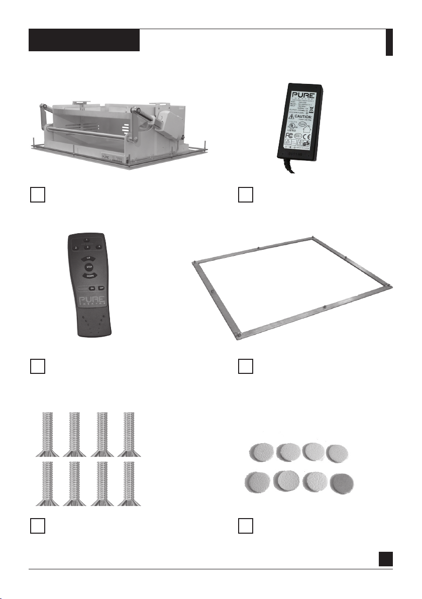
CHECKLIST
PROJECTOR LIFT
INFRA-RED REMOTE
POWER SUPPLY
TEMPLATE / MOUNTING FRAME
MOUNTING SCREWS
( M5 x 50mm long )
SCREW COVERS
1
Page 4
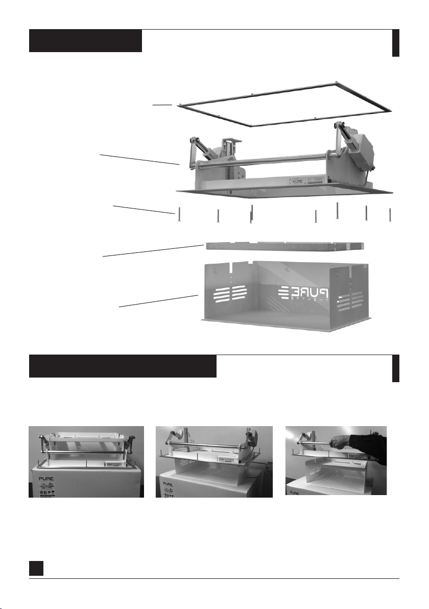
PARTS
TEMPLATE / MOUNTING FRAME
LIFT MECHANISM
MOUNTING SCREWS
PROJECTOR TRAY
PROJECTOR HOUSING
PRIOR TO INSTALLATION
IM P ORTA NT. Release projector housing prior to installation
Place lift on shipping box, then
connect power and lower using
remote control.
2
Remove four retaining screws,
located on either side of the
projector housing.
Separate the lift mechanism
from the projector housing.
Page 5

INSTALLATION
STEP 1. Find Joists, Pipes & Cables
Find the approximate position for your projector and
then locate and mark the position of any joists, wiring
and plumbing.
To aid installation a wood/metal sensor is
recommended. Available from most DIY stores
STEP 2. Mark Out Position
Now you have the joists marked, measure the exact
position for the projector lift and mark out using the
template supplied. Simply draw around the INSIDE
of the template and then mark all hole positions.
(We recommend holding the pr ojector in place, powe ring up a nd
testin g the scr een si ze with zoo m set to its m iddle p osition befor e
drilling holes.)
STEP 3. Drill Holes
Drill 8mm diameter holes through ceiling for
mounting screws. Be sure to drill the holes carefully
as these will have to line up with the projector lift.
STEP 4. Cut Slot
Cut out ceiling slot along the template line, taking
care to keep as close to the line as possible.
3
Page 6

INSTALLATION
Continued
STEP 5. Install Template
Place the template into the ceiling cavity and align
with holes.
If you are securing directly to joists cut the template
to suit and secure using No.8 screws into joists.
STEP 6. Install Transformer
Place the mains transformer into the ceiling cavity
and connect to the nearest suitable mains power
supply. Allow the 24v plug to hang down for easy
connection to the lift.
STEP 7. Install Projector Lift
Raise the lift up to the ceiling and connect
the power supply.
Note. Th e LEDS on th e lift s hould b oth light RED, then g o to
GREEN and YELLOW, and then OFF.
STEP 8. Test Lift Mechanism
Test mechanism up and down with remote control
then leave in the down position to allow projector
housing to be mounted.
4
Page 7

INSTALLATION
Continued
STEP 9. Install Power & AV Cable
Install the projector power and AV cables and leave
hanging down approximately 300mm.
This will aid installation of your projector.
STEP 10. Mount Projector
Mount projector to projector tray where inverted
mounting is required. Otherwise place projector
onto projector housing and place tray above.
Then raise up to ceiling and connect all power
and AV cables to the projector.
STEP 11. Install Projector Lift
Once power and AV cables are connected lift the
projector housing up into the lift mechanism and fit
four retaining screws, two on either side.
This will secure the projector housing to the lift
mechanism.
STEP 12. Secure And Test
Finally tighten all screws into ceiling.
(Fit s crew co vers on ce you hav e tested your inst allation.)
Your lift is now ready to use.
Please read the following pages for operating
instructions and programming options.
5
Page 8

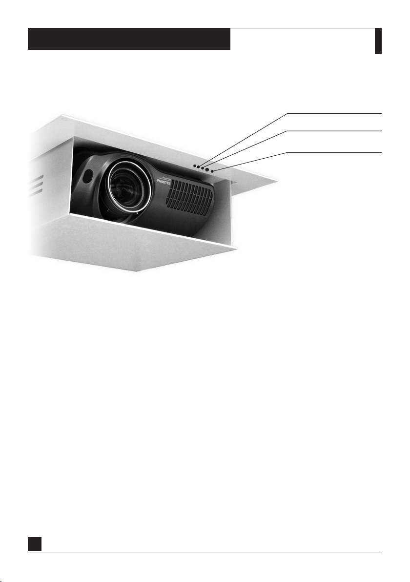
OPERATION LIGHTS
1
PROGRAMMING BUTTON
2
INFRA - RED SENSOR
3
SYSTEM STAUS LED (ILLUMINATES YELLOW & RED)
4
INFRA - RED STATUS LED (ILLUMINATES GREEN & RED)
5
TRIGGER MODULE STATUS LED (BLUE)
5
4
3
2
1
UP
REMOTE OPERATION
Once your lift is correctly installed and power has
been established simply use the supplied remote
control to operate the lift.
6
DOWN
Page 9

SETUP NOTES
____________________________________________________________________________
____________________________________________________________________________
____________________________________________________________________________
____________________________________________________________________________
____________________________________________________________________________
____________________________________________________________________________
____________________________________________________________________________
____________________________________________________________________________
____________________________________________________________________________
____________________________________________________________________________
____________________________________________________________________________
____________________________________________________________________________
____________________________________________________________________________
____________________________________________________________________________
____________________________________________________________________________
____________________________________________________________________________
____________________________________________________________________________
____________________________________________________________________________
7
Page 10
PROGRAMMING IR REMOTE
The projector lift can learn commands from the majority of domestic remote controls, allowing your
TV or projector remote to control the lift.
Programming a new remote will NOT disable the PureTheatre™ IR Remote.
SYST EM STATUS
IR STATU S LE D
PROGRAMMING BUTTON
PROGRAMMING IR REMOTE CONTROL:
STEP 1. Press programming button until SYSTEM STATUS LED & IR STATUS LED illuminate. (Approx 2 sec)
STEP 2. Then only SYSTEM LED illuminates. (Wa tch LEDS wh en programming as I R is very fast.)
STEP 3. Press desired UP button briefly on the domestic remote control.
The IR LED flashes GREEN for learning then RED for storing the new button.
STEP 4. Press UP button again briefly on domestic remote control.
The IR LED flashes GREEN for learning then RED for storing the new button.
STEP 5. Now press desired STOP button briefly on the domestic remote control.
The IR LED flashes GREEN for learning then RED for storing the new button.
STEP 6. Press STOP button again briefly on domestic remote control.
The IR LED flashes GREEN for learning then RED for storing the new button.
STEP 7. Now press desired DOWN button briefly on the domestic remote control.
The IR LED flashes GREEN for learning then RED for storing the new button.
STEP 7. Press DOWN button again briefly on domestic remote control.
The IR LED flashes to confirm success then extinguishes.
NOTE. When LEDS go out your domestic IR remote control is ready to use.
8
Page 11

FACTORY RESET
A factory reset will remove all stored IR commands and return the lif t back to factory default.
SYST EM STATUS
IR STATU S LE D
PROGRAMMING BUTTON
PERFORMING FACTORY RESET:
STEP 1. Press PROGRAMMING button for 20 seconds until
SYSTEM STATUS LED & IR STATUS LED illuminate RED.
STEP 2. Release PROGRAMMING button.
SYSTEM STATUS LED & IR STATUS LED will flash RED 3 times.
STEP 3. The screen will then RESTART.
The factory reset is now complete.
9
Page 12

supplied by
www.puretheatre.com
Pure Theatre - Unit 5 & 6 St Georges Road Industrial Estate, Telford, Shropshire, TF2 7QZ, UK.
tel: 0845 09400850 email: support@puretheatre.com web: www.puretheatre.com
 Loading...