

Page 1

PSBSH 1012A
v.1.0
PSBSH 13,8V/1A/1,2Ah/HERMETIC
Buffer switch mode power supply unit
EN*
Edition: 1’st from 16 th of November 2011
Supercedes the
-------------
edition.
Page 2

www.pulsar.pl PSBSH1012A
2
Features:
• DC 13,8V/1A uninterruptible power supply
• fitting battery: 1,2Ah/12V
• high efficiency 70%
• battery charging and maintenance control
• excessive discharging (UVP) protection
• battery output full protection against short-circuit
and reverse polarity connection
• battery charge current 0,2A
• START facility for manual battery connection
• LED indication
• FAC indication of the 230V power collapse
• adjustable times indicating 230V power failure
• protections:
•
SCP short-circuit protection
•
OLP overload protection
•
OHP overheat protection
•
overvoltage protection
•
against sabotage
•
IP65 ABS, hermetic enclosure
CONTENTS:
1. Technical description.
1.1 General description
1.2 Block diagram
1.3 Description of PSU components and connectors.
1.4 Specifications
2. Installation.
2.1 Requirements
2.2 Installation procedure
3. Operating status indication.
3.1 LED indication of operating status
3.2 Technical output
4. Operation and use.
4.1 Overload or short circuit of the PSU output
4.2 Battery-assisted operation
4.3 Maintenance
1. Technical description.
1.1 General description.
A buffer PSU is intended for an uninterrupted supply to alarm systems devices requiring stabilized voltage
of 12V/DC (+/-15%). The PSU provides voltage of 13,8 V DC. Current efficiency:
1. Output current 1,0A (without battery)
2. Output current 0,8A + 0,2A battery charge
Total device current + battery: 1A max.
In case of power decay, a battery back-up is activated immediately. Battery charge current is preset to
0,2A. The PSU is located in an ABS enclosure which can accommodate a 1,2Ah/12V battery and features a
microswitch indicating door opening (front cover).
Page 3
www.pulsar.pl PSBSH1012A
3
1.3 Description of PSU components and connectors.
Table 1. Elements of the PSU pcb (refer to chart 2).
Element no. Description
[1]
P
BAT
; pins - configuration of UVP battery protection function
• P
BAT
= protection (disconnection) of the battery off
• P
BAT
= protection (disconnection) of the battery on
TAC; pins J1, J2 - configuration of time lag of AC failure indication
• J1= , J2= time lag T= 5s
• J1= , J2= time lag T= 140s
• J1= , J2= time lag T= 1040s (17m 20s)
• J1= , J2= time lag T= 2h 20m 30s
Legend: jumper installed jumper removed
[2] START button (launching from battery)
[3] V
ADJ
potentiometer, voltage adjustment DC
[4] F
BAT
fuse in the battery circuit
[5]
Connectors:
+BAT- DC supply output of the battery
(+BAT= red, -BAT=black)
+AUX- DC supply output
(+AUX= +U, -AUX=GND)
FAC - AC absence technical output – relay assisted
Caution! In Fig.2. the set of contacts indicates potential-free status which corresponds
to AC power failure.
[6]
LED indication:
AC - LED for AC voltage
LB - LED for battery charge
AUX - LED for DC voltage
[7]
Connector to the external LED indicators: AC and AUX.
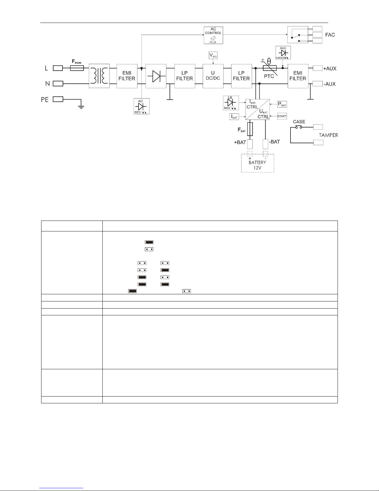
Fig.1. Block diagram of the PSU.
Page 4

www.pulsar.pl PSBSH1012A
4
Fig.2. View of the pcb.
Table 2. Elements of the PSU (refer to chart 3).
Element no. Description
[1]
Isolation transformer
[2]
Power-supply unit board (tab. 1, fig. 2)
[3] TAMPER; microswitches (contacts) ) for sabotage protection (NC)
[4] F
MAIN
witch in the power supply circuit (230V/AC)
[5]
L-N connector 230V/AC, PE protection connector
[6]
Battery connectors +BAT = red, - BAT = black
Fig.3. The view of the PSU.
Page 5

www.pulsar.pl PSBSH1012A
5
1.4 Specifications:
- electrical parameters (tab.3)
- mechanical parameters (tab.4)
- operation safety (tab.5)
- operating parameters (tab.6)
Electrical parameters (tab. 3)
Mains supply 230V/AC (-15%/+10%)
Current up to 0,14 A
Power frequency 50Hz
Supply power 17 W
Efficiency 70%
Output voltage 11,0 V÷ 13,8 V DC – buffer operation
10,0 V÷ 13,8 V DC – battery-assisted operation
Output current
1,0A (without battery)
0,8A + 0,2A battery charge
Output voltage setting, escalation and keeping
time
10ms / 34ms / 12ms
Voltage adjustment range 12,0 V÷ 14,5 V
Ripple 30 mV p-p max.
Current consumption by PSU systems 13 mA – battery-assisted operation
Battery charge current 0,2A
Short-circuit protection SCP
200% ÷ 250% of supply power
– current limitation and/or fuse
damage
in the battery circuit (fuse-element replacement
required)
Overload protection OLP
110% ÷ 150% (@25ºC) of power supply - limitation with the
PTC automatic fuse, manual restart (the fault requires the
disconnection of the DC output circuit)
Battery circuit SCP and reverse polarity
protections
2A - current limitation, F
BAT
fuse (in case of a failure, fuse-
element replacement required)
Excessive discharge protection UVP
U<10,0 V (± 5%) – disconnection of (- BAT) battery,
configuration by the P
BAT
jumper
Technical outputs:
- FAC; indicates AC power failure
- TAMPER indicates enclosure opening
- R-relay type, 1A@ 30Vdc/50Vac max.
time lag about 5s/140s/1040s/2h20m30s (+/-5%)
- microswitch, NC contacts (
enclosure closed
),
0,5A@50V DC (max.)
F
BAT
fuse
F
MAIN
fuse
F2A / 250V
T315mA / 250V
Mechanical parameters (tab. 4).
Enclosure dimensions 160 x 160 x 90 (WxHxD) [mm] (+/- 2)
Fixation 126 x 145 x Φ 6 x4 (WxH)
Fitting battery 1,2Ah/12V (SLA) max.
Net/gross weight 1,3/1,4 kg
Enclosure colour ABS, IP65, light grey
Closing Cheese head screw (at the front), lock assembly possible
Connectors Power supply: Φ0,63÷2,50 (AWG 22-10)
Outputs: Ф0,41÷1,63 (AWG 26-14),
Battery output BAT: 6,3F-2,5, 30cm,
TAMPER output: wires, 30cm
Notes
The enclosure has a removable mounting board with the PSU
systems.
Operation safety (tab.5).
Protection class PN-EN 60950-1:2007 I (first)
Degree of Protection PN-EN 60529: 2002 (U)
IP65
glands installation required:
P9 (Ф 4-8mm) x2
P13,5 (Ф 6-12mm) x1
Electrical strength of insulation:
- between input and output circuits of the PSU (I/P-O/P)
- between input circuit and PE protection circuit (I/P-FG)
3000 V/AC min.
1500 V/AC min.
Page 6

www.pulsar.pl PSBSH1012A
6
- between output circuit and PE protection circuit (O/P-FG) 500 V/AC min.
Insulation resistance:
- between input circuit and output or protection circuit
100 MΩ, 500V/DC
Operating parameters (tab.6).
Operating temperature -10ºC...+40ºC
Storage temperature -20ºC...+60ºC
Relative humidity 20%...90%, without condensation
Vibrations during operation unacceptable
Impulse waves during operation unacceptable
Direct insulation unacceptable
Vibrations and impulse waves during transport According to PN-83/T-42106
2. Installation
2.1 Requirements
The buffer PSU shall be mounted by a qualified installer with appropriate permissions and qualifications for
230V/AC installations and low-voltage installations (required and necessary for a given country). The device shall
be mounted in confined spaces, according to the environment class II, with normal air humidity (RH=90% max.
without condensation) and the temperature from -10°C to +40°C. The PSU shall operate in a vertical or horizontal
position.
1. Output current 1,0A (without battery)
2. Output current 0,8A + 0,2A battery charge
Total device current + battery: 1A max.
As the PSU is designed for a continuous operation and is not equipped with a power-switch, therefore an
appropriate overload protection shall be guaranteed in the power supply circuit. Moreover, the user shall be
informed about the method of unplugging (usually through assigning an appropriate fuse in the fuse-box). The
electrical system shall follow valid standards and regulations.
2.2 Installation procedure
1. Before installation, cut off the voltage in the 230V power-supply circuit.
2. Mount the glands (in a set, P9:Ф 4-8mm x2; P13,5: Ф 6-12mm x1) in the enclosure, considering the diameter of
power supply and receivers wires. Mind the location of the battery and additional equipment.
3. Mount the PSU in a selected location and connect the wires. (with the gland)
4. Connect the power cables (~230Vac) to L-N clips of the PSU. Connect the ground wire to the clip marked by the
earth symbol PE (PSU module connector). Use a three-core cable (with a yellow and green PE protection wire) to
make the connection. Lead the cables to the appropriate clips through the insulating bushing of the connection
board.
The shock protection circuit shall be performed with a particular care, i.e. the yellow and
green wire coat of the power cable shall stick to one side of the terminal - marked with
‘ ‘ symbol on the PSU enclosure. Operation of the PSU without the properly made and
fully operational shock protection circuit is UNACCEPTABLE! It can cause a device
failure or an electric shock.
5. Connect the receivers’ wires to the +AUX, -AUX terminals of the terminal box on the PSU pcb.
6. If necessary, connect the device conductors to the technical outputs:
- FAC; AC status indication (alarm panel, controller, indicator, LED, etc.) Use the TAC (J1,J2) jumper to determine
the indication time lag.
- TAMPER; the indicator preventing the PSU from unwanted opening
7. Using the P
BAT
pins, determine whether the function of disconnecting the discharged battery U<10V (+/-5%) is to
be on or off. The battery protection is on if the P
BAT
jumper is removed.
8. Activate the ~230V/AC supply (the AC red diode and AUX diode should be permanently illuminated)
9. Check the output voltage (the PSU voltage without load should amount to 13,6 V÷ 13,9 V, during battery
charging 11 V÷ 13,8 V). If the value of the voltage requires adjustment, it should be set by the V
ADJ
potentiometer,
monitoring the voltage at the AUX output of the PSU.
10. Connect the battery in accordance with the signs: +BAT red to ‘plus’, -BAT black to ‘minus’, (the LB diode light
should fade throughout the time of charging).
11. Once the tests and control operation have been completed, close the PSU.
Page 7

www.pulsar.pl PSBSH1012A
7
3. Operating status indication.
3.1 LED indication of operating status
The PSU is equipped with three diodes: AC, LB, AUX. They are placed on the pcb of the PSU and indicate
its operation status.
• AC - red diode: under normal status (AC supply) the diode is permanently illuminated. The absence of AC
supply is indicated by the AC diode going off.
• LB - red diode: indicates the battery charging process; the intensity of illumination is dependent on the
charging current.
• AUX - green diode: indicates the DC supply status in the output of the PSU. Under normal status, the
diode is permanently illuminated. In case of short-circuit or overload, the diode goes off.
3.2 Technical outputs:
The PSU is equipped with indication outputs.
• FAC - absence of AC supply output: - relay output indicates the absence of AC supply. In case of power
loss, the PSU will switch the relay contacts after a time period set by the T
AC
jumpers (J1, J2).
Caution! In Fig.2. the contact set in the potential-free status corresponds to a state with no AC power
(AC power failure).
• TAMPER - output indicates opening the power-supply unit: output as volt-free (potential-free) contacts
which indicate power-supply unit door status, unit closed: NC, unit opened: NO
4. Operation and use.
4.1 Overload or short circuit of the PSU output
The AUX output of the PSU is equipped with the PTC polymer fuse protection. If the load of the PSU
exceeds I
max
(load 110% ÷ 150% @25ºC of the PSU power), the output voltage is automatically cut off and
indicated by the green diode going off. Cut off the output load for approximately 1 minute to restore the output
power.
In case of the short-circuit to the AUX, BAT output, (load 200% ÷ 250% of the PSU power) or incorrect
connection of the battery, the fuse F
BAT
in the battery circuit becomes permanently damaged and the restoration of
the voltage at the BAT output requires the replacement of the fuse.
4.2 Battery–assisted operation
Immediate battery reverting in case of main power outage.
In order to run the PSU from the battery only, connect the BAT connectors in accordance with the signs:
+ BAT red to ‘plus’ and, - BAT black to 'minus’ then press the START button on the main board and hold it for 5
seconds.
The PSU contains a discharged battery disconnection system (UPV), configured through the
P
BAT
pins. The battery protection is on after removing the P
BAT
jumper.
4.3 Maintenance
Any and all maintenance operations may be performed following the disconnection of the PSU from the
power supply network. The PSU does not require performing any specific maintenance measures, however, in the
case of significant dust rate, its interior is recommended to be cleaned with compressed air. In case of fuse
replacement, use a replacement of the same parameters.
Page 8

www.pulsar.pl PSBSH1012A
8
WEEE MARK
According to the EU WEE Directive – It is required not to dispose of electric or
electronic waste as unsorted municipal waste and to collect such WEEE separately.
The power supply unit is adapted for a sealed lead-acid battery (SLA). After the operation period it must not be disposed of but recycled
according to the applicable law.
GENERAL WARRANTY CONDITIONS
1. Pulsar K. Bogusz Sp.j. (the manufacturer) grants a two-year warranty for the equipment, starting from the initial product date
of purchase placed on the receipt.
2. If a purchase proof is missing, a three-year warranty period is counted from the device’s production date.
3. The warranty includes free-of-charge repair or replacement with an appropriate equivalent (the selection is at the
manufacturer’s discretion) if the malfunction is due to the manufacturer, includes manufacturing or material defects, unless such
defects have been reported within the warranty period (item 1 and 2).
4. The equipment subject to warranty is to be brought to the place where it was purchased, or directly to the main office of the
manufacturer.
5. The warranty applies to complete equipment, accompanied by a properly filled warranty claim with a description of the defect.
6. Should the claim be accepted, the manufacturer is obliged to provide warranty repairs, at the earliest convenienve, however
not later that within 14 days from the delivery to the service centre of the manufacturer.
7. The repair period mentioned in item 6 may be prolonged, if there are no technical possibilities to carry out the repairs, or if the
equipment has been conditionally accepted, due to the breaking warranty terms by the claimant.
8. All the services rendered by force of the warranty are carried out at the service centre of the manufacturer, exclusively.
9. The warranty does not cover the defects of the equipment, resulting from:
- reasons beyond the manufacturer's control,
- mechanical damage,
- improper storage and transport,
- use that violates the operation manual or equipment’s intended use
- fortuitous events, including lightning discharges, power failures, fire, flood, high temperatures and chemical agents,
- improper installation and configuration (in defiance with the manual),
10. The warranty is void in any of the following circumstances:
- construction changes
- repairs carried out by any unauthorized service center
- damage or removal of warranty labels
- modifications of the serial number
11. The liability of the manufacturer towards the buyer is limited to the value of the equipment, determined according to the
wholesale prices suggested by the manufacturer on the day of purchase.
12. The manufacturer takes no reponsibility for the defects that result from:
- the damaging, malfunctioning or inability to operate the equipment
- defects that result from using the equipment outside its stated specifications and operating parameters failing to abide by the
recommendations and requirements contained in the manual, or the use of the equipment.
Pulsar K.Bogusz Sp.j.
Siedlec 150, 32-744 Łapczyca, Poland
Tel. (+48) 14-610-19-40, Fax. (+48) 14-610-19-50
e-mail: biuro@pulsar.pl, sales@pulsar.pl
http:// www.pulsar.pl, www.zasilacze.pl
 Loading...