

Pulsar PSBOC30024100 Instruction Manual

PSBOC30024100
v.1.0
PSBOC 27,6V/10A/OC
Enclosed buffer switch mode power supply unit
with technical outputs.
EN**
Edition: 2 from 01.06.2016
Supercedes edition: 1 from 30.11.2015

www.pulsar.pl PSBOC30024100
2
Features:
27,6VDC/10A uninterrupted supply*
wide range of supply voltage 176÷264VAC
built-in power factor correction system (PFC)
high efficiency 85%
battery charge and maintenance control
deep discharge battery protection (UVP)
battery charging current 1A/2A/4A jumper
selectable
forced cooling - built-in fan
battery output protection against short circuit and
reverse polarity connection
LED indication
EPS technical output indicating AC power loss
– OC and relay type
PSU technical output indicating PSU failure
– OC and relay type
LoB technical output indicating battery low voltage
– OC and relay type
protections:
SCP short-circuit protection
OVP over voltage protection
surge protection
OLP overload protection
overheat protection OHP
warranty – 2 year from the production date
CONTENTS:
1. Technical description.
1.1 General description
1.2 Block diagram
1.3 Description of PSU components and connectors
1.4 Specifications
2. Installation.
2.1 Requirements
2.2 Installation procedure
3. Operating status indication.
3.1 LED indication of operating status
3.2 Technical outputs
4. Operation and use.
4.1 Overload or short circuit of the PSU output
4.2. Battery-assisted operation
4.3. Maintenance
1. Technical description.
1.1 General description
A buffer PSU is intended for an uninterrupted supply to devices requiring stabilized voltage of 24V DC
(+/-15%). The PSU provides voltage of U=27,6V DC current efficiency:
1. Output current 9A + 1A battery charging*
2. Output current 8A + 2A battery charging*
3. Output current 6A + 4A battery charging*
Total device current + battery charging current: 10A max*.
In the case of power failure from prime supply, the unit is instantly switched to battery assisted operation.
The power supply unit features: short circuit, overload protection, overvoltage and thermal overload protection. The
power supply is fitted with a fan for forced cooling, switching on depending on the temperature and the load of the
power supply.
*
See chart 1
www.pulsar.pl PSBOC30024100
3
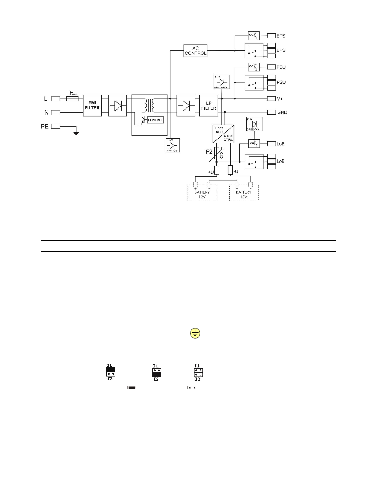
1.2 Block diagram. (fig.1).
Fig.1. Block diagram of the PSU.
1.3 Description of PSU components and connectors.
Table 1. Elements of the PSU (see fig. 2).
Element no.
Description
[1]
LED indicating presence of AC power
[2]
LED indicating presence of DC power
[3]
LED indicating correct battery voltage
[4]
EPS - AC absence technical output – relay type
[5]
PSU - output indicating DC absence/PSU failure – relay type
[6]
LoB - output indicating battery low voltage – relay type
[7]
EPS - AC absence technical output – OC type
[8]
PSU - output indicating DC absence/PSU failure - OC type
[9]
LoB - output indicating battery low voltage - OC type
[10]
V
ADJ
- potentiometer, DC voltage adjustment
[11]
+V ,-V- DC supply output
[12]
L-N 230V/AC power connector, PE protection connector
[13]
Battery connectors: +BAT =red, - BAT = black
[14]
LED indication on the front panel
[15]
Battery charging current selection:
Ibat =1 A, Ibat=2A Ibat=4A
Legend: dip switch installed dip switch removed
 Loading...