

Pulsar PSAC 04244SEP User Manual

PSAC 0
4244
SEP
v.1.0
PSAC 24VAC/4A/4x1A/SEP AC power supply for CCTV
EN
Edition: 1 from 06.12.2011
Replaces edition:

2
Features of the power supply unit:
• 4 independent, galvanically separated outputs
• Voltage regulation (by jumper)
• LED optical signalisation
• AW technical output
CONTENTS:
1. Technical description.
1.1. General description
1.2. Block diagram
1.3. Description of elements and connectors of the power supply
1.4. Technical parameters
2. Installation.
2.1. Requirements
2.2. Procedure of installation
3. Signalling the operation of power supply.
3.1. Optical signalling
3.2. Technical output
4. Service and operation.
4.1. Overload and short-circuit
4.2. Maintenance
• protections:
• SCP short-circuit protection
• overvoltage protection
• overload OLP
• against sabotage
• OHP thermal protection of transformer
1. Technical description.
1.1. General description.
AC/AC PSAC 04244SEP power supply is using for supplying CCTV devices requiring AC voltage of 24 V with overall
efficiency of 4A@24V AC. The power supply is housed in a metal case (colour RAL 9003). The casing is equipped
with a micro switch that signals the opening of the doors (front panel).
Information about additional elements of PSAC 04244SEP power supply
- module of the AC/AC power supply in ABS casing, MSC 1512 (module of MSC 12V/1.5A or 24V/1A power supply,
exchanged voltage) allowing to create a 24 V AC and 12 V DC/24 V DC supply system.
3
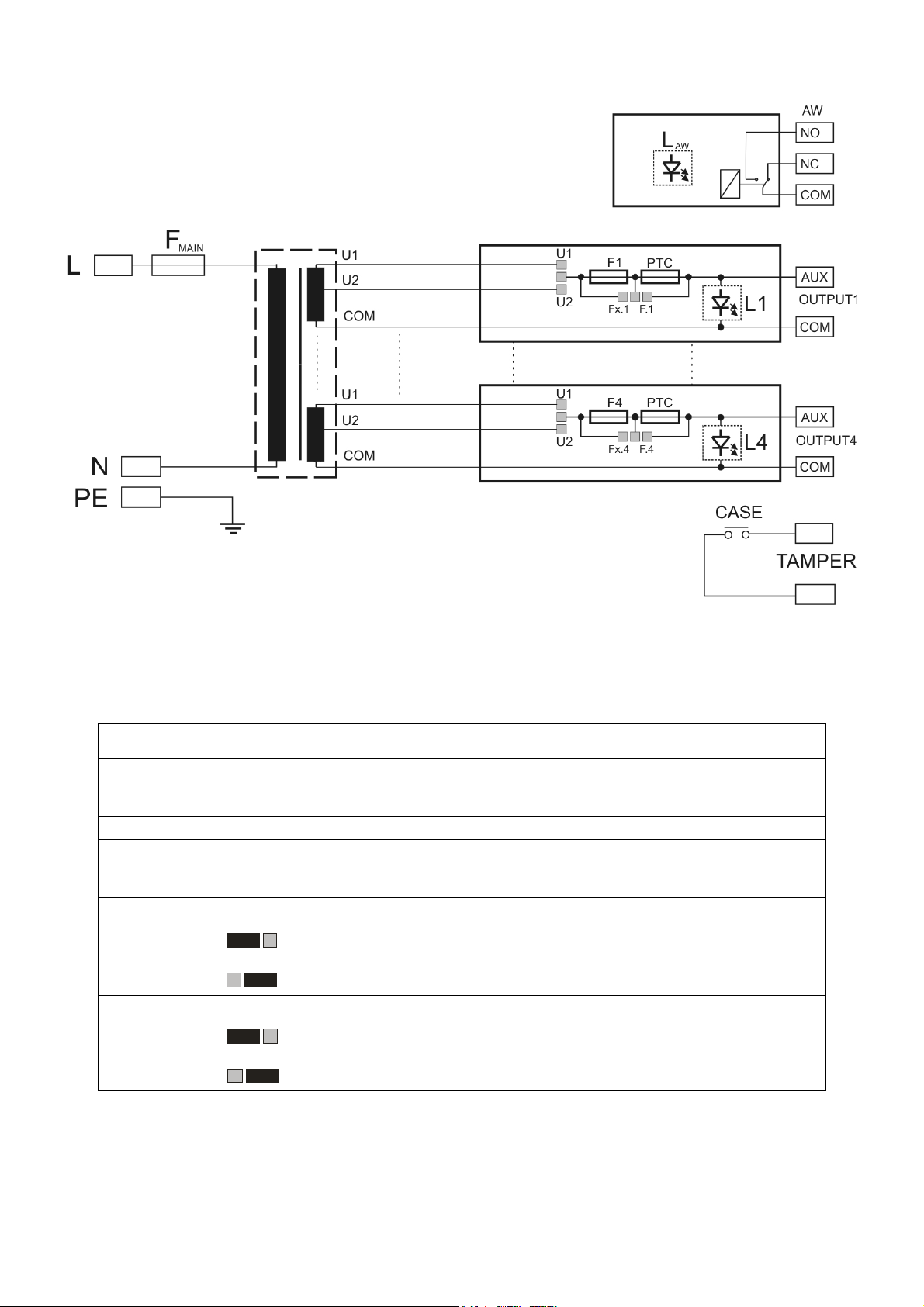
1.2. Block diagram (fig.1).
Fx
Fx.x
Fx
Fx.x
U2
U1
U2
U1
Fig.1. Block diagram of the power supply.
1.3. Description of elements and connectors of the power supply ( table 1, table 2, fig. 2, fig.4).
Table 1. Terminal and elements of LB4-SEP.
Element No.
[Fig. 2]
[1] L1÷L4 - LED (green) signalling the status of L1=OUT1 output, etc.
[2] F1÷F4 fuses in output circuits, F1=OUT1 etc.
[3] COM-U1-U2 Input of the AC supply (required transformer separation)
[4] OUT1, OUT2, OUT3, OUT4 independently protected outputs
[5] LAW LED (red) signalling failure of one of the outputs (activation of a safety device)
[6]
[7]
[8]
AW output signalling failure of one of the outputs, relay type.
Attention! Fig.2 shows non-potential state of relay i.e. the state of failure
Jumper of the change in PTC/fuse-element safety device type
Fx jumper used, fuse-element protection device selected
Fx.x jumper used, polymer protection device selected
Jumper of the output voltage change (independently for each output):
U2 jumper used, voltage on OUTx= U2 output
Description of LB4-SEP elements
U1 jumper used, voltage on OUTx= U1 output
 Loading...