

Page 1
Studio Pro
Live Streaming and Video Conferencing Camera
User Manual
Model No. PT-STUDIOPRO
V1.0
(English)
Please check ptzoptics.com for the most up to date version of this document.
v1_1 rev 5-23
Page 2

Table of Contents
Preface .......................................................... 3
Precautions . . . . . . . . . . . . . . . . . . . . . . . . . . . . . . . . . . . . . . . . . . . . . . . . . . . . . . . 3
Warning .............................................................................. 3
Warranty ......................................................... 4
Supplied Accessories ............................................... 4
FCC Statement .............................................. 4
NDI®|HX Connection ................................................ 5
Connection Guide .................................................. 6
Dimensional Drawings ............................................... 7
Features ......................................................... 8
IR Remote Controller Guide .......................................... 11
On Screen Display. . . . . . . . . . . . . . . . . . . . . . . . . . . . . . . . . . . . . . . . . . . . . . . . . . 22
On Screen Display. . . . . . . . . . . . . . . . . . . . . . . . . . . . . . . . . . . . . . . . . . . . . . . . . . 23
Network Connection ................................................ 29
Discovering your Network Info .................................. 30
Web UI ........................................................... 32
Maintenance and Troubleshooting ..................................... 53
Camera Maintenance .......................................... 53
Unqualied Applications ....................................... 53
Troubleshooting .............................................. 53
Control ..................................................... 54
2
v1_1 rev 5-23
Page 3
Preface
Congratulations on receiving your new PTZOptics Studio Pro live streaming and video
conferencing camera.This manual introduces the function, installation, and operation of the HD
camera. Prior to installation and usage, please read the manual thoroughly. Please contact our
Support team if you have any questions or issues with this process.
Precautions
This product can only be used in the specied conditions in order to avoid any damage to the unit
itself.
• Don’t subject the camera to rain or moisture.
• Don’t remove the cover. Removal of the cover may result in an electric shock in addition to
voiding the warranty. In case of abnormal operation, contact https://community.ptzoptics.
com/s/.
• Never operate outside of the specied operating temperature range, humidity, or with any
other power supply than the one originally provided with the unit.
• Please use a soft dry cloth to clean the unit. If the unit is very dirty, clean it with diluted neutral detergent; do not use any type of solvents, which may damage the surface.
Warning
• Electrical Safety
Installation and operation must be in accordance with national and local electric safety
standards. Do not use any power supply other than the one originally supplied with this
camera.
• Polarity of Power Supply
The power supply output for this product is 12V DC with a maximum current supply of
2A. Polarity of the power supply plug is critical and is as follows:
• Handling
Ŝ Avoid any stress, vibration, or moisture during transportation, storage, installation,
and operation.
Ŝ Do not expose the camera to any corrosive solid, liquid, or gas to avoid damage to
the cover which is made of a plastic material.
Ŝ Never power the camera on before installation is complete.
• Do not dismantle the camera – PTZOptics is not responsible for any unauthorized
modication or dismantling.
3
v1_1 rev 5-23
Page 4

Warranty
PTZOptics includes a limited parts & labor warranty for all PTZOptics manufactured cameras. The warranty is
valid only if PTZOptics receives proper notice of such defects during the warranty period. PTZOptics, at its
option, will repair or replace products that prove to be defective. PTZOptics manufacturers its hardware
products from parts and components that are new or equivalent to new in accordance with industry standard
practices.
Supplied Accessories
When you unpack your camera, make sure that all the supplied
accessories are included:
• Camera 1
• AC Power Supply 1
• IR Remote 1
• Quick Start Guide 1
• AAA Batteries 2
• USB-A to USB-C Screw Locking Cable 1
• LED Panel Light 1
FCC Statement
This equipment has been tested and found to comply with the limits for a Class A digital device,
pursuant to part 15 of the FCC Rules. These limits are designed to provide reasonable protection against
harmful interference when the equipment is operated in a commercial environment. This equipment generates,
uses, and can radiate radiofrequency energy and, if not installed and used in accordance with the instruction
manual, may cause harmful interference to radio communications. FCC Caution: Any changes or modication
not expressly approved by the party responsible for compliance could void the user’s authority to operate this
equipment. Operation is subject to the following two conditions: This device may not cause harmful
interference, and (2) this device must accept any interference received, including interference that may cause
undesired operation.
• Warning - This is a class A product. In a domestic environment, this product may cause radio inter-
ference in which case the user may be required to take adequate measures.
• Remote Control Battery Safety Information - Store batteries in a cool and dry place. Do not throw
away used batteries in the trash. Properly dispose of used batteries through specially approved
disposal methods. Remove the batteries if they are not in use for long periods of time. Battery
leakage and corrosion can damage the remote control. Do not use old batteries with new batteries.
Do not mix and use dierent types of batteries: alkaline, standard (carbon-zinc) or rechargeable
(nickel-cadmium). Do not dispose of batteries in a re. Do not attempt to short-circuit the battery
terminals.
Copyright Notice
The entire contents of this manual / guide, whose copyright belongs to PTZOptics, may not be cloned, copied, or translated in any way
without the explicit permission of the company. The product specications referred to in this document are for reference only and as
such are subject to updating at any time without prior notice.
©2023 | PTZOptics | All Rights Reserved
4
v1_1 rev 5-23
Page 5

NDI®|HX3 Connection
The NDI®|HX connection allows you to connect and control your camera through any NDI
compatible hardware or software on your Local Area Network. Once your camera is setup on a LAN,
you can utilize the NDI®|HX3 connection.
NDI® Setup:
1. Download and install the latest NDI®|HX Tools from https://www.ndi.tv/tools.
2. Congure your camera settings from the NDI Cong tab in the camera’s web interface.
3. Select your camera within the NDI®|HX compatible device.
4. Select your camera. The NDI feed will utilize the camera’s device friendly name.
NewTek® NDI®, NDI® & NDI®|HX3 are all registered trademarks by NewTek®.
Please note that your NDI License key is non-transferrable.
5
v1_1 rev 5-23
Page 6
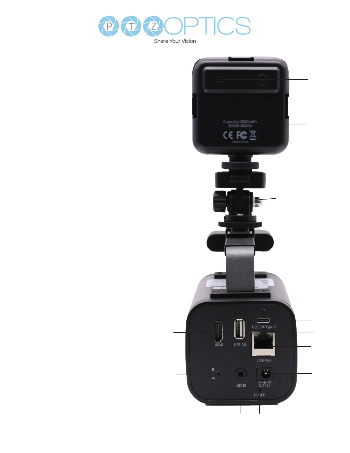
Connection Guide
Item Name
1. HDMI Interface
2. Horizontal and Vertical Screen Switch
3. MIC IN Interface
4. Power Indicator
5. DC 12V Power Interface
6. LAN (PoE) Interface
7. USB 3.0 Interface (Type C)
8. USB 2.0 Interface (Does not supply Video)
9. Cold Shoe Tilt Mount
10. LED Light Panel
11. USB C Port
11
10
9
8
1
2
3 4
6
v1_1 rev 5-23
7
6
5
Page 7
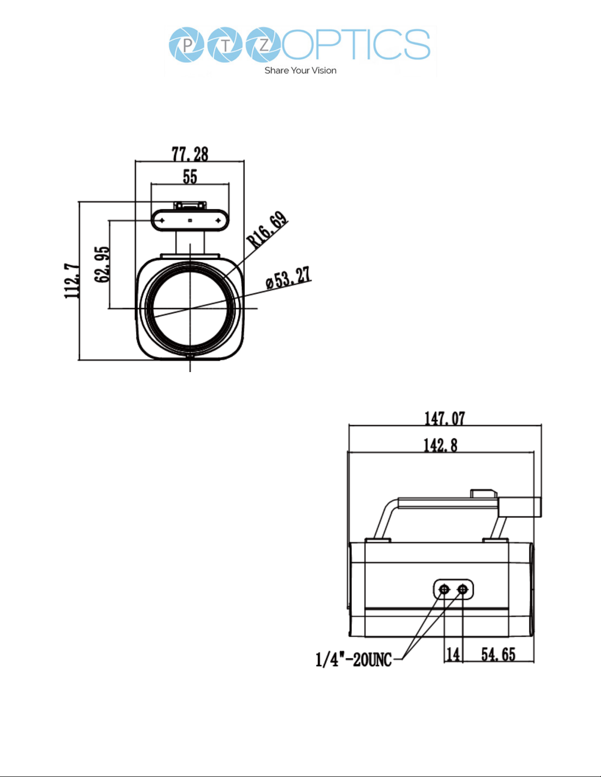
Dimensional Drawings
7
v1_1 rev 5-23
Page 8

Features
• Full-featured USB Interface
Full-featured USB Type-C interface, compatible with USB 3.0 and USB 2.0, supports
audio, encoding output, and UVC 1.5.
• Precise Focus
Equipped with TOF close-range assisted focusing, combined with advanced focusing
algorithms, it can quickly and stably focus regardless of distance.
• 1080P HD Image
Adopts a new generation of Panasonic 1/2.8-inch, 2.07 million eective pixel
high-quality HD CMOS sensor, which can achieve high-quality images with a
maximum resolution of 1920x1080.
• Easy to Use
Supports Portrait and Landscape screen switching. Suitable for horizontal and vertical
screen display screens. USB plug-and-play, simple and fast. The cold shoe mount allows
the panel light or an external microphone to be integrated to enrich the scene.
• HDMI 1.4b
Supports HDMI 1.4b, can directly output uncompressed 1080P60 original video.
• 72.5° Wide Lens + 12x Optical Zoom
Adopts 72.5° high quality ultra wide-angle lens, optical zoom up to 12x, and supports
16x digital zoom.
• LED Panel Light
Color adjustment with warm/natural light and dimming range. Can be charged by Studio
Pro USB 2.0 port.
• Supports PoE
Supports PoE power control, video and audio only needs one network cable to
complete.
• Network Encoding Output
Supports dual network video stream output (rst stream, second stream).
• Multiple Interfaces
Supports HDMI, USB 3.0 and network interface, can output 1080P60 video at the same
time.
• Three Power Supply Methods
Supports USB 5V, DC 12V power adapter and PoE power supply.
8
v1_1 rev 5-23
Page 9
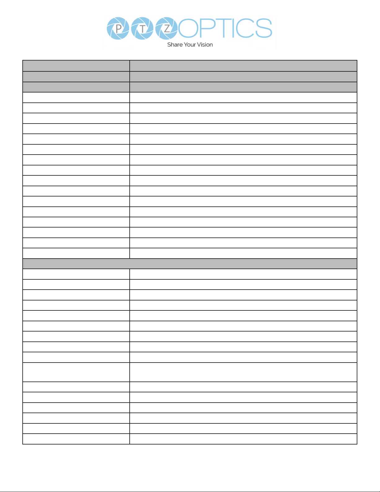
Model PT-STUDIOPRO
Type PTZOptics Studio Pro
Camera
Video System 1080P@60 / 50 / 30, 1080I@60 / 50, 720P@60 / 50
Sensor 1/2.8", CMOS, Eective Pixels 2.07M
Scanning Mode Progressive
Lens f=3.5mm ~ 42.3mm, F1.8 ~ F2.8
Zoom 16X Digital Zoom, 12X Optical Zoom
Minimal Illumination 0.5 Lux @ (F1.8, AGC ON)
Shutter 1/30s ~ 1/190s
White Balance Auto, Indoor, Outdoor, One Push, Manual, VAR
Digital Noise Reduction 2D & 3D Digital Noise Reduction
Video S/N ≥55dB
Horizontal Angle of View 6.9° ~ 72.5°
Vertical Angle of View 3.9° ~ 44.8°
Horizantal & Vertical Flip Supported
Image Freeze Supported
LED Color Adjustment with warm.Natural Light and Dimming range
Number of Presets 255
Network Features
Operating System Windows 7 / 8.1 / 10 / 11, Mac OS, Linux, Android,
Color System / Compression YUY2 / H.264 / MJPEG
Video Format YUY2 (ISOC), H.264 AVC, H.264 SVC, MJPEG
USB Audio Supported
USB Video Protocol UVC 1.1 ~ 1.5
UVC PTZ Support
Video Compression H.264 / HEVC/H.265* / MJPEG
Video Stream Capable of up to two simultaneous video streams.
First Stream Resolution 1920x1080, 1280x720, 640x480, 640x360
Second Stream Resolution 1280x720, 1024x576, 720x576(50Hz support), 720x480(60Hz
support), 720x408, 640x360, 480x270, 320x240, 320x180
Video Bit Rate 32Kbps ~ 102400Kbps
Bit Rate Control CBR, VBR
Frame Rate 50Hz: 1fps ~ 50fps, 60Hz: 1fps ~ 60fps
Audio Compression AAC
Audio Bit Rate 96Kbps, 128Kbps, 256Kbps
Support Protocols TCP/IP, HTTP, RTSP, RTMP, ONVIF, DHCP, and Multicast.
9
v1_1 rev 5-23
Page 10
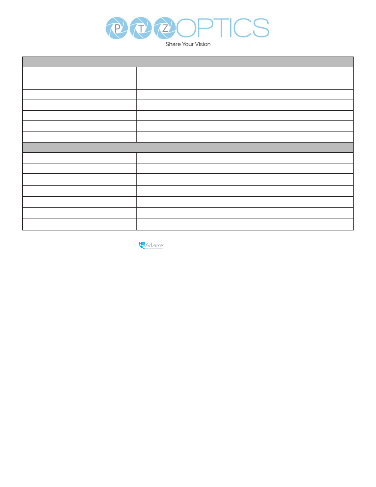
Interface
USB Interface USB 3.0: Type C, Supplies Video
USB 2.0: Type A, Only supplies power to 3rd Party Devices
HD Output HDMI 1.4b
Audio Interface MIC IN: 3.5mm
Network Interface 1 x RJ45: 10M/100M, Adaptive Ethernet Port, support PoE
Power Jack JEITA type (DC IN 12V)
H & V Screen Switch Vertical Screen, Horizontal Screen
Physical Parameter
Input Voltage DC 12V / USB 5V / PoE(802.3af)
Current Consumption 12V 1.0A (Max.) / 5V 1.5A (Max.)
Operating Temperature 14F ~ 104F (-10°C ~ 40°C)
Storage Temperature -40F~ 140F (-40°C ~ 60°C)
Power Consumption 6W
Dimensions 5.8 x 4.4 x 3.0 (inches) / 147 x 113 x 77 (mm)
Weight 1.54 lbs / 0.7Kg
* HEVC/H.265 is a registered trademark of Access Advance®, LLC
10
v1_1 rev 5-23
Page 11
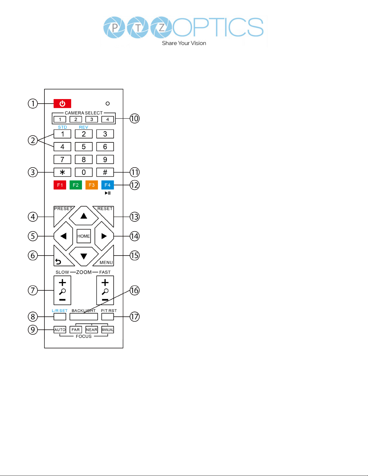
IR Remote Controller Guide
3. * Button
For multiple functions. Typically used when
calling shortcuts.
4 & 13. Set / Clear Preset Buttons
Set Preset: Store a preset position
[PRESET] + Numeric button (0-9):
Setting a corresponding numeric key
preset position.
Clear Preset: Erase a preset position.
[RESET] + Numeric button (0-9) or;
[*] + [#] + [RESET]: Erase all presets
5 & 14. Pan / Tilt Control Buttons
Press the arrow buttons to
pan and tilt. Press the [HOME] button to
face the camera back to the front.
(PTZ Cameras Only)
6. Return Button
Press the [RETURN] button to go back
a previous menu within the OSD menu.
1. Standby Button
Press this button to enter standby mode.
Press it again to enter normal mode.
Note: Power consumption in standby
mode is approximately half of the normal
mode.
2. Position Buttons
To set or call preset position.
7. Zoom Buttons
Zoom+: Zoom In (Slow and fast speed).
Zoom-: Zoom Out (Slow and fast
speed).
8. L / R Set Buttons
Set the Left & Right direction of the
remote control.
[L/R SET] + [1]: Normal direction
[L/R SET] + [2]: Left and right directions
will be reversed.
Press buttons simultaneously.
9. Focus Buttons
Used for focus adjustment.
[AUTO]: Automatically focus image on
the center object.
[MANUAL]: Allow for manual control
of focus. Make adjustments using [FAR]
(focus on far object) and [NEAR] (focus
on near object).
10. Camera Address Select Buttons
Press the camera select button
corresponding to the camera in which
you want to operate.
11
v1_1 rev 5-23
Page 12

11. # Button
For multiple functions. Typically used
when calling shortcuts
12. Multiple Function Buttons
Function 1. For setting camera IR address.
• Press 3 keys in sequence to set the
camera IR address as follows:
[*] > [#] > [F1]: Address 1
[*] > [#] > [F2]: Address 2
[*] > [#] > [F3]: Address 3
[*] > [#] > [F4]: Address 4
Function 2. Image Freeze function
Press [F4] to enable Image Freeze. After
enabled, “Freeze” will be displayed in
the upper left corner for 5 seconds.
To disable Image Freeze, press [F4]
again.
15. Menu Settings
Used for adjusting the camera On Screen
Display (OSD) settings
[MENU]: Open or close the On Screen
Display menu
16. Backlight Button
Use to enable or disable backlight
compensation.
Note: Only eective in auto exposure
mode.
Note: If there is light behind the subject,
the subject may appear darker.
In this case, use Backlight Compensation to
enhance image.
17. P / T RST Button
Perform camera self-calibrate pan and tilt
movement. (PTZ Cameras Only)
IR Shortcut Functions:
[*] > [#] >[1]: Display OSD menu in
English
[*] > [#] > [3]: Display OSD menu in
Chinese
[*] > [#] > [4]: Show IP address
[*] > [#] > [6]: Quickly restore the
default settings
[*] > [#] > [8]: Show the camera version
[*] > [#] > [9]: Quickly set mount mode
(ip / normal)
[*] > [#] > [MANUAL]: Resets IP
information to default
[#] > [*] > [7]: OnePush White Balance
Trigger (Camera must be in
OnePush White Balance)
[*] > [*] > [AUTO] Performs the “Startup
Dance” on repeat
[#] > [*] > [4]: Enable Dynamic IP address
[#] > [*] > [#] > [1]: Sets IP address to
192.168.100.81
[#] > [*] > [#] > [2]: Sets IP address to
192.168.100.82
[#] > [*] > [#] > [3]: Sets IP address to
192.168.100.83
[#] > [*] > [#] > [4]: Sets IP address to
192.168.100.84
[#] > [*] > [#] > [5]: Sets IP address to
192.168.100.85
[#] > [*] > [#] > [6]: Sets IP address to
192.168.100.86
[#] > [*] > [#] > [7]: Sets IP address to
192.168.100.87
[#] > [*] > [#] > [8]: Sets IP address to
192.168.100.88
[#] > [*] > [#] > [9]: Sets IP address to
192.168.100.89
[#] > [*] > [#] +>[0]: Sets IP address to
192.168.100.80
[#] > [*] > [7]: OnePush White Balance
Trigger (Camera must be in
OnePush White Balance)
12
v1_1 rev 5-23
Page 13
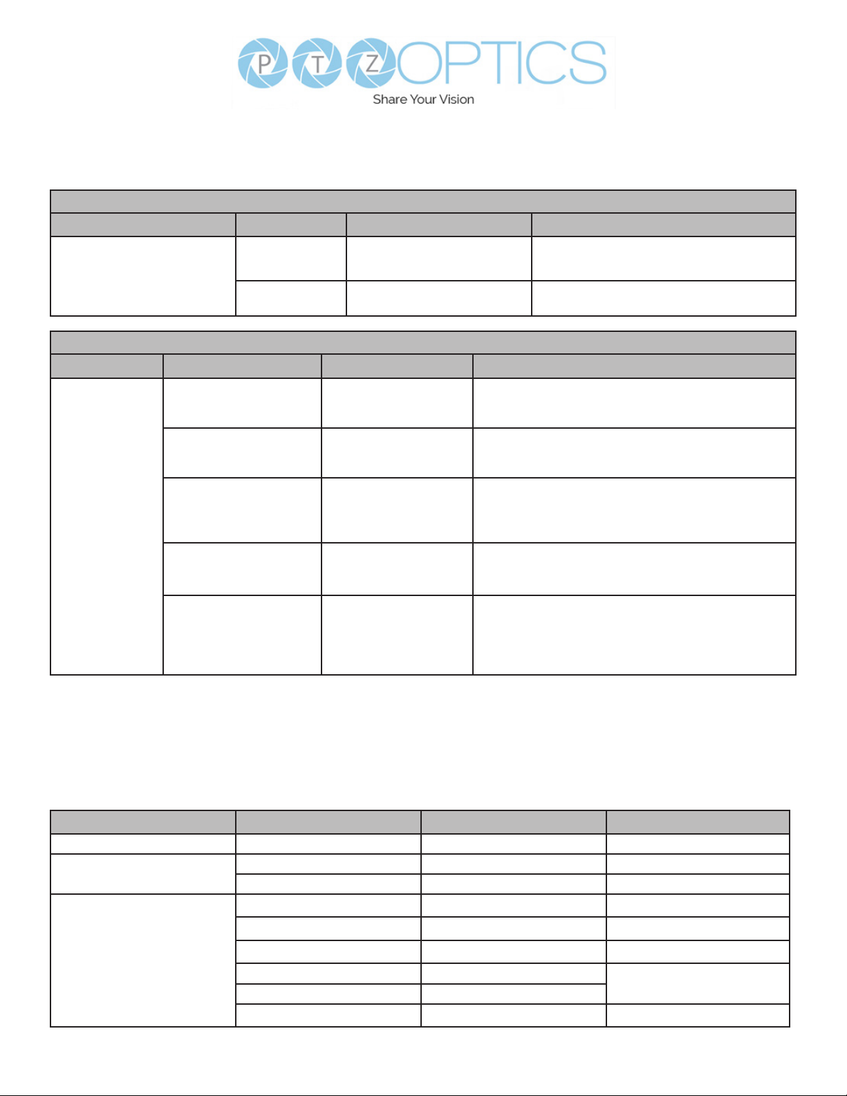
PTZOptics Serial VISCA & VISCA over IP Command List
Part 1: Camera Issued Commands
ACK / Completion Messages
Command Function Command Packet Comments
ACK
ACK / Completion Messages
Completion
z0 4y FF
(y: Socket No.)
z0 5y FF
(y: Socket No.)
Error Messages
Command Function Command Packet Comments
Error Messages
Syntax Error
Command Buer Full
Command Canceled
No Socket
Command Not Executable
z0 60 02 FF
z0 60 03 FF
z0 6y 04 FF
(y: Socket No.)
z0 6y 05 FF
(y: Socket No.)
z0 6y 41 FF
(y: Execution command
Socket No. Inquiry
command: 0)
Returned when the command format is dierent or
when a command with illegal command parameters is
accepted.
Indicates that two sockets are already being used
(executing two commands) and the command could not
be accepted when received
Returned when a command which is being executed in
a socket specied by the cancel command is canceled.
The completion message for the command is not
returned.
Returned when no command is executed in a socket
specied nu the cancel command, or when an invalid
Socket No. is specied
Returned when a command cannot be executed due
to current conditions. For example: when commands
controlling the focus manually are received during auto
focus mode.
Returned when the command is accepted.
Returned when the command has been
executed.
VISCA over IP control: z = 9
Serial VISCA control: z = Camera Address + 8
Part 2:PTZOptics Command List
Command Function Command Packet Comments
IF Clear Broadcast
CAM_Power
CAM_Zoom
On
O
Stop
Tele (Standard)
Wide (Standard)
Tele (Variable)
Wide (Variable)
Direct
8x 01 00 01 FF
8x 01 04 00 02 FF
8x 01 04 00 03 FF
8x 01 04 07 00 FF
8x 01 04 07 02 FF
8x 01 04 07 03 FF
8x 01 04 07 2p FF
8x 01 04 07 3p FF
8x 01 04 47 p q r s FF
13
I/F Clear
Power On/O
p = 0 (low) – 7 (high)
v1_1 rev 5-23
Page 14
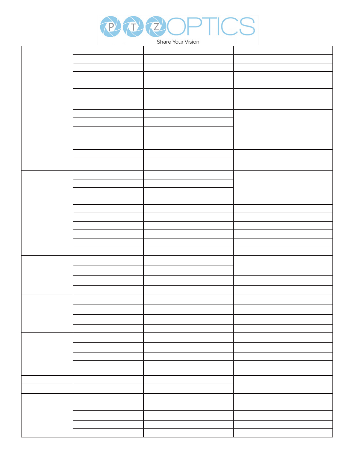
CAM_Focus
CAM_AFSensitivity
CAM_WB
Stop
Far (Standard)
Near (Standard)
Far (Variable)
Near (Variable)
Direct
Auto Focus
Auto / Manual
Snap Focus
Focus Lock
Focus Unlock
High
Low
Auto
Indoor
Outdoor
OnePush
Manual
ColorTemperature (VAR)
OnePush Trigger
Reset
8x 01 04 08 00 FF
8x 01 04 08 02 FF
8x 01 04 08 03 FF
8x 01 04 08 2p FF
8x 01 04 08 3p FF
8x 01 04 48 0p 0q 0r 0s FF
8x 01 04 38 02 FF
8x 01 04 38 03 FF
8x 01 04 38 10 FF
8x 01 04 38 04 FF
8x 0a 04 68 02 FF
8x 0a 04 68 03 FF
8x 01 04 58 01 FF
8x 01 04 58 02 FF
8x 01 04 58 03 FF
8x 01 04 35 00 FF
8x 01 04 35 01 FF
8x 01 04 35 02 FF
8x 01 04 35 03 FF
8x 01 04 35 05 FF
8x 01 04 35 20 FF
8x 01 04 10 05 FF
8x 01 04 03 00 FF
p = 0 (low) – 7 (high)
pqrs: Zoom Position
(0x04 0x00 0x00 0x00 = Full Zoom in.
0x00 0x00 0x00 0x00 = Full Zoom out.)
Auto Focus On / OManual Focus
Focus image while maintaining manual
focus mode.
Prevents any other operation or
command from adjusting the current
focus state.
AF Sensitivity High / Normal / LowNormal
Normal Auto mode
Indoor mode
Outdoor mode
One Push White Balance mode
Manual control mode
Color Temperature mode
One Push White Balance Trigger
Default Bright position
CAM_RGain
CAM_BGain
CAM_ColorTemp
CAM_RTuning Direct
CAM_BTuning
CAM_AE
Up
Down
Direct
Reset
Up
Down
Direct
Reset
Up
Down
Direct
Direct
Full Auto
Manual
Shutter Priority
Iris Priority
Bright
8x 01 04 03 02 FF
8x 01 04 03 03 FF
8x 01 04 43 00 00 0p 0q FF
8x 01 04 04 00 FF
8x 01 04 04 02 FF
8x 01 04 04 03 FF
8x 01 04 44 00 00 0p 0q FF
8x 01 04 20 00 FF
8x 01 04 20 02 FF
8x 01 04 20 03 FF
8x 01 04 20 0p 0q FF
8x 0A 01 12 pq FF
8x 0A 01 13 pq FF
8x 01 04 39 00 FF
8x 01 04 39 03 FF
8x 01 04 39 0A FF
8x 01 04 39 0B FF
8x 01 04 39 0D FF
pq: Red Gain
Manual control of blue gain
pq: Blue Gain
Default ColorTemperature settings
pq: ColorTemperature position: 0x00:
2500K ~ 0x37: 8000K
pq: Red / Blue Tuning position 0x00
(-10) ~ 0x14 (+10)
Automatic Exposure mode
Manual exposure mode
Shutter priority auto exposure mode
Iris priority auto exposure mode
Bright manual exposure mode
14
v1_1 rev 5-23
Page 15
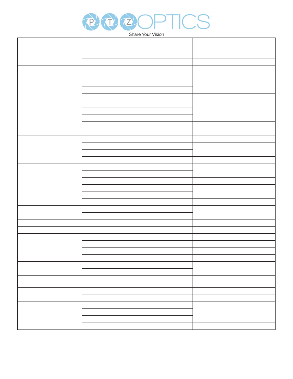
Reset
CAM_Iris
CAM_DRC Direct
CAM_Shutter
CAM_Gain
CAM_Bright
CAM_ExpComp
CAM_NR(2D)Mode
CAM_NR(2D)Level
CAM_NR(3D)Level
CAM_WDRStrength
CAM_Backlight
CAM_Flicker
CAM_ApertureMode
(Sharpness)
CAM_Aperture
(sharpness)
Up
Down
Direct
Reset
Up
Down
Direct
Reset
Up
Down
Direct
Gain Limit
Reset
Up
Down
Direct
On
O
Reset
Up
Down
DIrect
Auto
Manual
Direct
Direct
Reset
Up
Down
Direct
On
O
-
Auto
Manual
Reset
Up
Down
Direct
8x 01 04 0B 00 FF
8x 01 04 0B 02 FF
8x 01 04 0B 03 FF
8x 01 04 4B 00 00 0p 0q FF
8x 01 06 01 0E 0E 03 02 FF
8x 01 04 0A 00 FF
8x 01 04 0A 02 FF
8x 01 04 0A 03 FF
8x 01 04 4A 00 00 0p 0q FF
8x 01 04 0C 00 FF
8x 01 04 0C 02 FF
8x 01 04 0C 03 FF
8x 01 04 0C 00 00 0p 0q FF
8x 01 04 2C 0p FF
8x 01 04 0D 00 FF
8x 01 04 0D 02 FF
8x 01 04 0D 03 FF
8x 01 04 0D 00 00 0p 0q FF
8x 01 04 3E 02 FF
8x 01 04 3E 03 FF
8x 01 04 0E 00 FF
8x 01 04 0E 02 FF
8x 01 04 0E 03 FF
8x 01 04 4E 00 00 0p 0q FF
8x 01 04 50 02 FF
8x 01 04 50 03 FF
8x 01 04 53 0p FF
8x 01 04 54 0p FF
8x 01 04 21 00 FF
8x 01 04 21 02 FF
8x 01 04 21 03 FF
8x 01 04 51 00 00 0p 0q FF
8x 01 04 33 02 FF
8x 01 04 33 03 FF
8x 01 04 23 0p FF
8x 01 04 05 02 FF
8x 01 04 05 03 FF
8x 01 04 02 00 FF
8x 01 04 02 02 FF
8x 01 04 02 03 FF
8x 01 04 42 00 00 0p 0q FF
Default Iris position
Iris setting
pq: Iris position
p: 0(low) - 8(high)
Default shutter position
Shutter setting
pq: Shutter position
Gain Setting
pq: Gain Position
p: Gain Position
Default Bright position
Bright setting
pq: Bright position
Exposure Compensation On / O
Default ExpComp position
ExpComp setting
pq: ExpComp position
ND2D Auto/Manual
p: NR Setting (0: O, level 1 to 5)
p: NR Setting (0: O, level 1 to 8)
pq: WDR Level Positon
Backlight Compensation On / O
p: Flicker settings - (0: O, 1: 50Hz, 2:
60Hz)
Aperture Control
pq: Aperture Gain
x = Camera Address + 8
15
v1_1 rev 5-23
Page 16
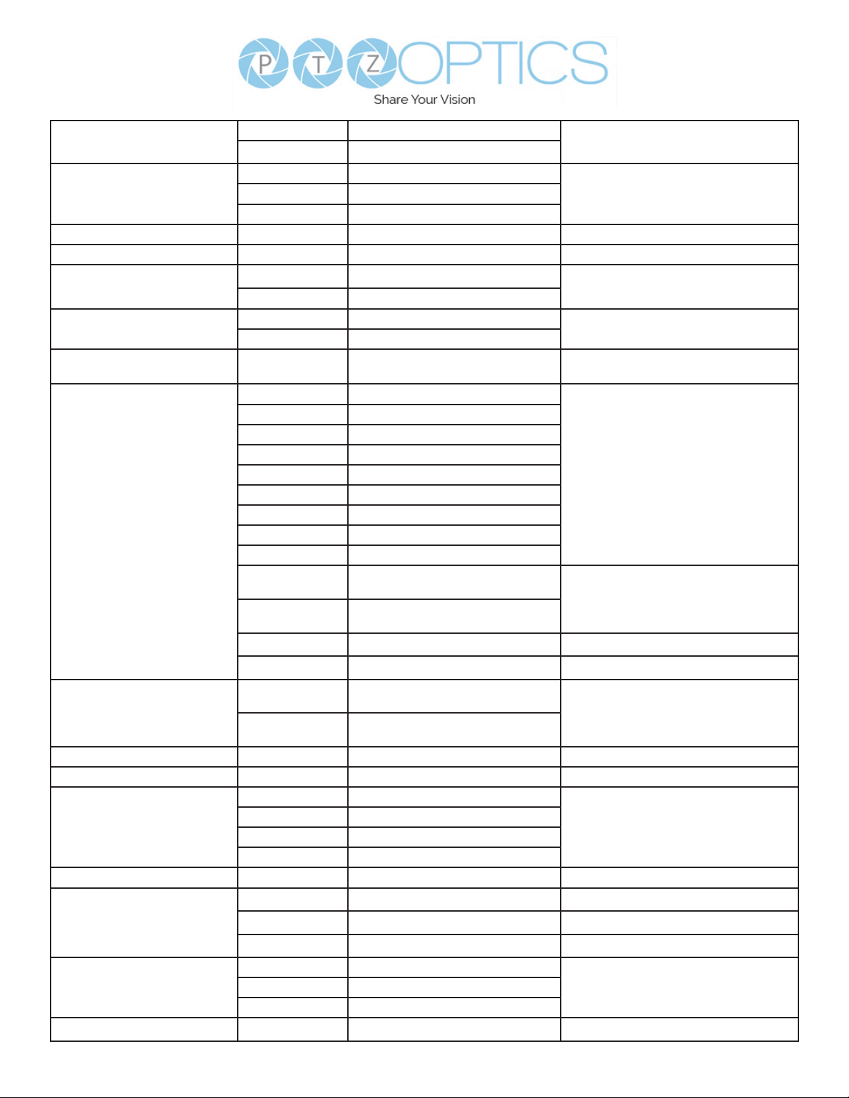
CAM_Picture Eect
CAM_Memory
Preset_Recall_ Speed Preset Speed
CAM_ImageFreeze Freeze Image
CAM_LR_ Reverse
CAM_PictureFlip
CAM_ColorGain
Pan_TiltDrive
Pan_TiltLimitSet
CAM_Brightness Direct
CAM_Contrast Direct
CAM_Flip
CAM_SettingSave Save
CAM_AWB Sensitivity
CAM_AFZone
O
B&W
Reset
Recall
On
O
On
O
Direct
Up
Down
Left
RIght
UpLeft
UpRight
DownLeft
DownRight
Stop
AbsolutePosition
RelativePosition
Home
Reset
LimitSet
LimitClear
O
Flip-H
Flip-V
Flip-HV
High
Normal
Low
Top
Bottom
8x 01 04 63 00 FF
8x 01 04 63 04 FF
8x 01 04 3F 00 pp FF
8x 01 04 3F 01 pp FF
8x 01 04 3F 02 pp FF
8x 01 06 01 p FF
8x 01 04 62 0p FF
8x 01 04 61 02 FF
8x 01 04 61 03 FF
8x 01 04 66 02 FF
8x 01 04 66 03 FF
8x 01 04 49 00 00 00 0p FF
8x 01 06 01 VV WW 03 01 FF
8x 01 06 01 VV WW 03 02 FF
8x 01 06 01 VV WW 01 03 FF
8x 01 06 01 VV WW 02 03 FF
8x 01 06 01 VV WW 01 01 FF
8x 01 06 01 VV WW 02 01 FF
8x 01 06 01 VV WW 01 02 FF
8x 01 06 01 VV WW 02 02 FF
8x 01 06 01 VV WW 03 03 FF
8x 01 06 02 VV WW 0Y 0Y 0Y
0Y 0Z 0Z 0Z 0Z FF
8x 01 06 03 VV WW 0Y 0Y 0Y
0Y 0Z 0Z 0Z 0Z FF
8x 01 06 04 FF
8x 01 06 05 FF
8x 01 06 07 00 0W 0Y 0Y 0Y
0Y 0Z 0Z 0Z 0Z FF
8x 01 06 07 01 0W 07 0F 0F
0F 07 0F 0F 0F FF
8x 01 04 A1 00 00 0p 0q FF
8x 01 04 A2 00 00 0p 0q FF
8x 01 04 A4 00 FF
8x 01 04 A4 01 FF
8x 01 04 A4 02 FF
8x 01 04 A4 03 FF
8x 01 04 A5 10 FF
8x 01 04 A9 00 FF
8x 01 04 A9 01 FF
8x 01 04 A9 02 FF
8x 01 04 AA 00 FF
8x 01 04 AA 01 FF
8x 01 04 AA 02 FF
Picture Eect setting
pp: Memory number (=0 to 127)Set
P: Speed grade (0x01 ~ 0x18)
p: 2 ON; p: 3 OFF
Image Flip Horizontal On / O
Image Flip Vertical On / O
P: Color Gain setting 0h (60%) to
Eh(200%)
VV: Pan Speed 0x01 (low) to 0x18 (high)
WW: Tilt Speed 0x01 (low) to 0x14 (high)
YYYY: Pan position, ZZZZ: Tilt position
W: 1 (UpRight), 0: DownLeft
YYYY: Pan position, ZZZZ: Tilt position
pq: Brightness position
pq: Contrast position
Single Command for video ip
Save Current Setting
AF Zone weight selectCenter
16
v1_1 rev 5-23
Page 17
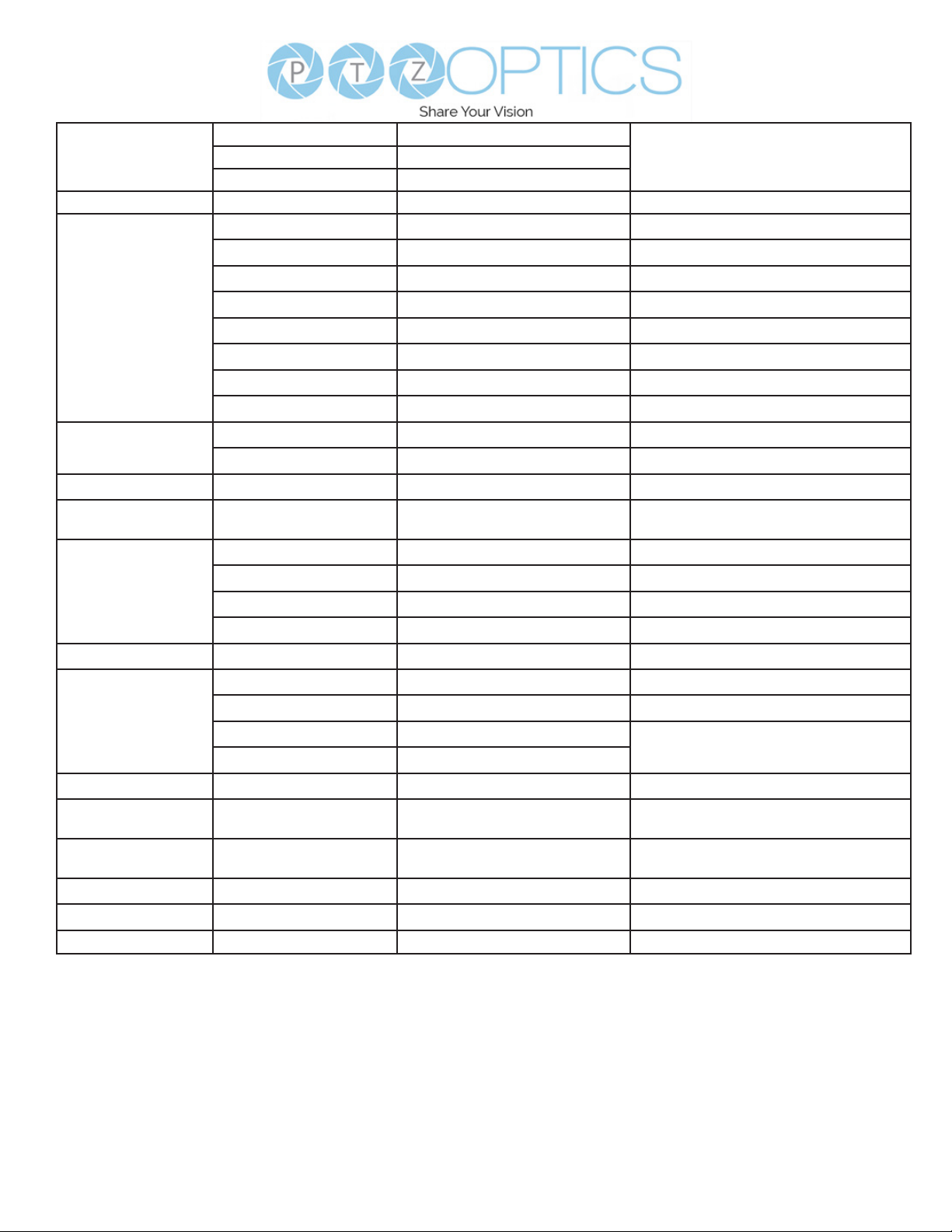
Top
CAM_AFZone
Bottom
CAM_ColorHue Direct
Open / Close
Close
Navigate Up
OSD_Control
CAM_LensType
CAM_AFCalibration
CAM_TallyLight
CAM_NDIMode
CAM_Multicast Mode
CAM_PTZMotion Sync
CAM_UACStatus
CAM_RTMPSet
CAM_FocusRange
CAM_SettingSave
CAM_SettingReset
CAM_NetworkReset
Navigate Down
Navigate Left
Navigate Right
Enter
Return
Type1
Type 2
Re-Calibrates Focus
Tally Light Control
High
Medium
Low
O
Multicast Mode
PTZ Motion Sync On
PTZ Motion Sync O
PTZ MS Upper Speed Limit
PTZ MS Lower Speed Limit
Toggle USB Audio
Toggle RTMP
Focus Range
Save
Reset
Reset Network Parameters
8x 01 04 AA 00 FF
8x 01 04 AA 01 FF
8x 01 04 AA 02 FF
8x 01 04 4F 00 00 00 0p FF
8x 01 04 3F 02 5F FF
8x 01 06 06 03 FF
8x 01 06 01 0E 0E 03 01 FF
8x 01 06 01 0E 0E 03 02 FF
8x 01 06 01 0E 0E 01 03 FF
8x 01 06 01 0E 0E 02 03 FF
8x 01 06 06 05 FF
8x 01 06 06 04 FF
8x 0A 01 04 1B 00 FF
8x 0A 01 04 1B 01 FF
8x 0A 01 03 12 FF
8x 0A 02 02 0p FF
8x 0B 01 01 FF
8x 0B 01 02 FF
8x 0B 01 03 FF
8x 0B 01 04 FF
8x 0B 01 23 0p FF
8x 0A 11 13 02 FF
8x 0A 11 13 03 FF
8x 0A 11 14 pq FF
8x 0A 11 14 pq FF
8x 2a 02 a0 04 0p FF
8x 0A 11 A8 pq FF
8x 0A 11 42 0p rs tv FF
8x 01 04 A5 10 FF
8x 01 04 A0 10 FF
8x 0A 01 AA FF
AF Zone weight selectCenter
P: Color Hue setting 0h (-14°) to Eh (+14°)
Corrects camera focus capabilities
p=1: Flashing, p=2: Light always on, p=3:
normal
p=1: On, p=2: O
pq: Speed stage
p=2: On, p=3: O
p: 1 Stream 1; p: 2 stream 2; q: 2 ON, q: 3
OFF
p=0: O p=1: On, rs: furthest position(0x00
~ 0x0B), tv: nearest position(0x00 ~ 0x0B)
Save Current Setting
Reset to Factory Settings
VISCA over IP control: x = 1
Serial VISCA control: x = Camera Address + 8
17
v1_1 rev 5-23
Page 18
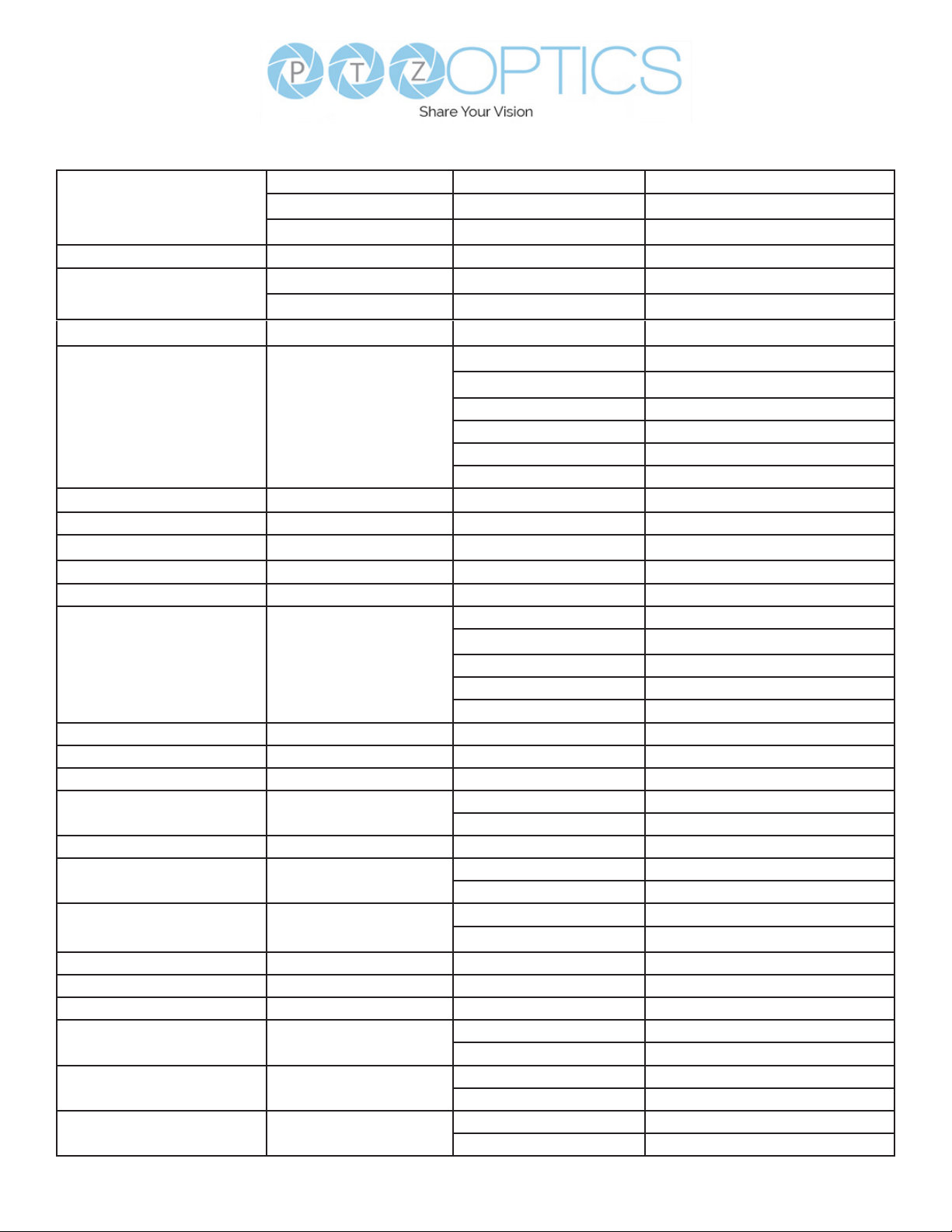
Part 3: PTZOptics Query Command List
CAM_PowerIng
CAM_ZoomPosIng
CAM_FocusAFModeIng
CAM_FocusPosIng
CAM_WBModeIng
CAM_RGainIng
CAM_BGainIng
CAM_ColorTempIng
CAM_RTuningInq
CAM_BTuningInq
CAM_AEModeIng
CAM_ShutterPosIng
CAM_IrisPosIng
CAM_BrightPosInq
CAM_ExpCompModeInq
CAM_ExpCompPosInq
CAM_BacklightModeInq
CAM_Noise2DModeInq
CAM_Noise2DLevel
CAM_Noise3DLevel
CAM_FlickerModeInq
CAM_ApertureModeInq
(Sharpness)
SYS_MenuModeInq
CAM_PictureEectModeInq
8x 09 04 00 FF y0 50 02 FF
y0 50 03 FF
y0 50 04 FF
8x 09 04 47 FF y0 50 0p 0q 0r 0s FF
8x 09 04 48 FF y0 50 02 FF
y0 50 03 FF
8x 09 04 35 FF y0 50 0p 0q 0r 0s FF
y0 50 00 FF
y0 50 01 FF
8x 09 04 35 FF
8x 09 04 43 FF y0 50 00 00 0p 0q FF
8x 09 04 44 FF y0 50 00 00 0p 0q FF
8x 09 04 12 FF 90 50 00 00 0p 0q FF
8x 09 04 13 FF 90 50 00 00 0p 0q FF
8x 09 04 39 FF
8x 09 04 4A FF y0 50 00 00 0p 0q FF
8x 09 04 4B FF y0 50 00 00 0p 0q FF
8x 09 04 4D FF y0 50 00 00 0p 0q FF
8x 09 04 3E FF
8x 09 04 4E FF y0 50 00 00 0p 0q FF
8x 09 04 33 FF
8x 09 04 50 FF
8x 09 04 53 FF y0 50 0p FF
8x 09 04 54 FF y0 50 0p FF
8x 09 04 55 FF y0 50 0p FF
8x 09 04 05 FF
8x 09 06 06 FF
8x 09 04 63 FF
y0 50 02 FF
y0 50 03 FF
y0 50 05 FF
y0 50 pq FF
y0 50 00 FF
y0 50 03 FF
y0 50 0A FF
y0 50 0B FF
y0 50 0D FF
y0 50 02 FF
y0 50 03 FF
y0 50 02 FF
y0 50 03 FF
y0 50 02 FF
y0 50 03 FF
y0 50 02 FF
y0 50 03 FF
y0 50 02 FF
y0 50 03 FF
y0 50 02 FF
y0 50 04 FF
On
O (Standby)
Internal Power Circuit Error
pqrs: Zoom position
AutoFocus
Manual Focus
pqrs: Focus Position
Auto
Indoor
Outdoor
OnePush
Manual
ColorTemperature
pq: Red Gain
pq: Blue Gain
pq: ColorTemperature position
pq: 0x00 ~ 0x14
pq: 0x00 ~ 0x14
Full Auto
Manual
Shutter Priority (SAE)
Iris Priority (AAE)
Bright
pq: Shutter position
pq: Iris position
pq: Bright position
On
O
pq: ExpComp position
On
O
Auto Noise 2D
Manual Noise 2D
Noise Reduction (2D) p: 0 to 5
Noise Reduction (3D) p: 0 to 5
p=0: O, 1: 50Hz, 2: 60Hz
Auto Sharpness
Manual Sharpness
On
O
O
B&W
18
v1_1 rev 5-23
Page 19
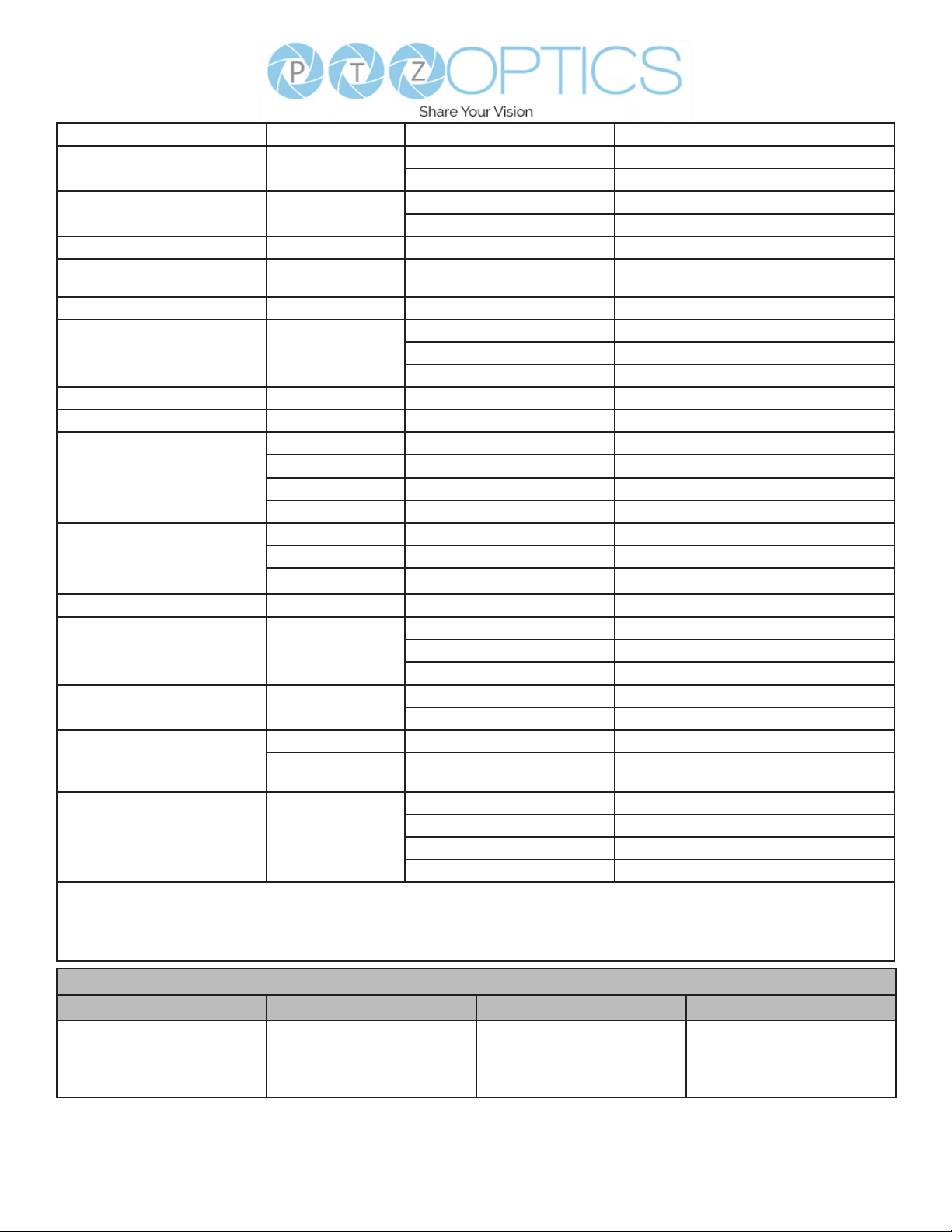
CAM_MemoryInq
CAM_LR_ReverseIng
CAM_PictureFlipIng
CAM_ColorGainIng
CAM_PanTiltPosIng
CAM_GainLimitIng
CAM_AFSensitivityIng
CAM_BrightnessIng
CAM_ContrastIng
CAM_FlipIng
CAM_AFZone
CAM_ColorHueIng
CAM_AWBSensitivityInq
CAM_UACInq
CAM_PTZMotionSyncInq
CAM_RTMPInq
VISCA over IP control: x = 1
Serial VISCA control: x = Camera Address + 8
8x 09 04 3F FF y0 50 0p FF
8x 09 04 61 FF
8x 09 04 66 FF
8x 09 04 49 FF y0 50 00 00 00 0p FF
8x 09 06 12 FF y0 50 0w 0w 0w 0w 0z 0z
8x 09 04 2C FF y0 50 0q FF
8x 09 04 58 FF
8x 09 04 A1 FF y0 50 00 00 0p 0q FF
8x 09 04 A2 FF y0 50 00 00 0p 0q FF
8x 09 04 A4 FF y0 50 00 FF
8x 09 04 AA FF y0 50 00 FF
8x 09 04 4F FF y0 50 00 00 00 0p FF
8x 09 04 A9 FF
8x 2A 02 A0 04 FFy0 50 02 FF
8x 09 11 13 FF 90 50 0p FF
8x 09 11 14 FF 90 50 pq FF
8x 09 11 53 FF
y0 50 02 FF
y0 50 03 FF
y0 50 02 FF
y0 50 03 FF
0z 0z FF
y0 50 01 FF
y0 50 02 FF
y0 50 03 FF
y0 50 01 FF
y0 50 02 FF
y0 50 03 FF
y0 50 01 FF
y0 50 02 FF
y0 50 00 FF
y0 50 01 FF
y0 50 02 FF
y0 50 03 FF
90 50 00 FF
90 50 01 FF
90 50 02 FF
90 50 03 FF
p: Memory number last operated
On
O
On
O
P: Color gain 0h (60%) to Eh (200%)
WWWW: Pan position, ZZZZ: Tilt position
p: Gain limit
High
Normal
Low
pq: Brightness position
pq: Contrast position
O
Flip-H
Flip-V
Flip-HV
Top
Center
Bottom
P: Color Hue 0h (-14°) to Eh (+14°)
High
Normal
Low
On
O
p: MotionSync setting 0: O, 1: On
pq: Max MotionSync speed 00 (185) ~ 09
(230)
Stream 1 OFF; Stream 2 OFF
Stream 1 ON; Stream 2 OFF
Stream 1 OFF; Stream 2 ON
Stream 1 ON; Stream 2 ON
Block Inquiry Command List
Command Command Packet Inquiry Packet Comments
CAM_LensBlockIng
8x 09 7E 7E 00 FF y0 50 0u 0u 0u 0u 00 00
0v 0v 0v 0v 00 0w 00
FF
UUUU: Zoom position
VVVV: Focus position
W.bit0: Focus mode 1: Auto, 0:
manual
19
v1_1 rev 5-23
Page 20
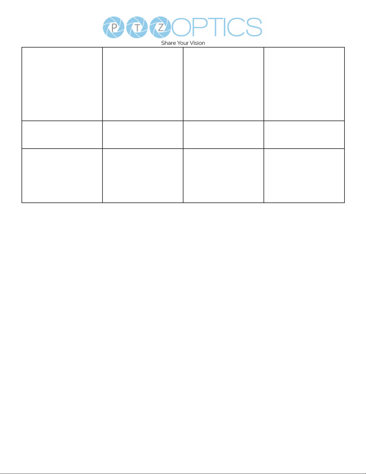
CAM_CameraBlockIng
CAM_OtherBlockIng
CAM_EnlargmentBlockIng
VISCA over IP control: x = 1
Serial VISCA control: x = Camera Address + 8
VISCA over IP control: y = 9
Serial VISCA control: y = Camera Address + 8
8x 09 7E 7E 01 FF y0 50 0p 0p 0q 0q 0r 0s
8x 09 7E 7E 02 FF y0 50 0p 0q 00 0r 00 00
8x 09 7E 7E 03 FF y0 50 00 00 00 00 00 00
tt 0u vv ww 00 xx 0z
FF
00 00 00 00 00 00 00
FF
00 0p 0q rr 0s 0t 0u FF
PP: Red Gain,
QQ: Blue Gain
R: WB Mode,
S: Aperture
TT: AE Mode,
U.bit2: Backlight
U.bit1: Exposure Comp,
VV: Shutter position.
WW: Iris position,
XX Bright position,
Z: Exposure Comp position
P.bit0: Power 1: On, 0: O,
Q.bit2: LR Reverse: 1: On, 0:
O R.bit3~0: Picture Eect
Mode
P: AF sensitivity
Q.bit0: Picture ip: 1: On, 0:
O RR.bit6~3: Color Gain (0h
(60%) to Eh (200%))
S: Flip 0: O, 1: Flip-H, 2: FlipV,
3: Flip-HV
T.bit2~0: NR2D level
U: Gain limit
20
v1_1 rev 5-23
Page 21
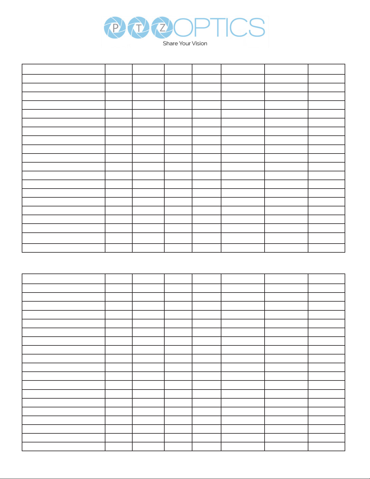
Part 4: Pelco-D Protocol Command List
Function Byte1 Byte2 Byte3 Byte4 Byte5 Byte6 Byte7
Up 0xFF Address 0x00 0x08 Pan Speed Tilt Speed SUM
Down 0xFF Address 0x00 0x10 Pan Speed Tilt Speed SUM
Left 0xFF Address 0x00 0x04 Pan Speed Tilt Speed SUM
Right 0xFF Address 0x00 0x02 Pan Speed Tilt Speed SUM
Zoom In 0xFF Address 0x00 0x20 0x00 0x00 SUM
Zoom Out 0xFF Address 0x00 0x40 0x00 0x00 SUM
Focus Far 0xFF Address 0x00 0x80 0x00 0x00 SUM
Focus Near 0xFF Address 0x00 0x00 0x00 0x00 SUM
Set Preset 0xFF Address 0x00 0x03 0x00 Preset ID SUM
Clear Preset 0xFF Address 0x00 0x05 0x00 Preset ID SUM
Call Preset 0xFF Address 0x00 0x07 0x00 Preset ID SUM
Auto Focus 0xFF Address 0x00 0x2B 0x00 0x01 SUM
Manual Focus 0xFF Address 0x00 0x2B 0x00 0x02 SUM
Query Pan Position 0xFF Address 0x00 0x51 0x00 0x00 SUM
Query Pan Position Response 0xFF Address 0x00 0x59 Value High Byte Value Low Byte SUM
Query Tilt Position 0xFF Address 0x00 0x53 0x00 0x00 SUM
Query Tilt Position Response 0xFF Address 0x00 0x5B Value High Byte Value Low Byte SUM
Query Zoom Position 0xFF Address 0x00 0x55 0x00 0x00 SUM
Query Zoom Position Response 0xFF Address 0x00 0x5D Value High Byte Value Low Byte SUM
Query Zoom Position Response 0xFF Address 0x00 0x5D Value High Byte Value Low Byte SUM
Part 5: Pelco-P Protocol Command List
Function Byte1 Byte2 Byte3 Byte4 Byte5 Byte6 Byte7
Up 0xFF Address 0x00 0x08 Pan Speed Tilt Speed SUM
Down 0xFF Address 0x00 0x10 Pan Speed Tilt Speed SUM
Left 0xFF Address 0x00 0x04 Pan Speed Tilt Speed SUM
Right 0xFF Address 0x00 0x02 Pan Speed Tilt Speed SUM
Zoom In 0xFF Address 0x00 0x20 0x00 0x00 SUM
Zoom Out 0xFF Address 0x00 0x40 0x00 0x00 SUM
Focus Far 0xFF Address 0x00 0x80 0x00 0x00 SUM
Focus Near 0xFF Address 0x00 0x00 0x00 0x00 SUM
Set Preset 0xFF Address 0x00 0x03 0x00 Preset ID SUM
Clear Preset 0xFF Address 0x00 0x05 0x00 Preset ID SUM
Call Preset 0xFF Address 0x00 0x07 0x00 Preset ID SUM
Auto Focus 0xFF Address 0x00 0x2B 0x00 0x01 SUM
Manual Focus 0xFF Address 0x00 0x2B 0x00 0x02 SUM
Query Pan Position 0xFF Address 0x00 0x51 0x00 0x00 SUM
Query Pan Position Response 0xFF Address 0x00 0x59 Value High Byte Value Low Byte SUM
Query Tilt Position 0xFF Address 0x00 0x53 0x00 0x00 SUM
Query Tilt Position Response 0xFF Address 0x00 0x5B Value High Byte Value Low Byte SUM
Query Zoom Position 0xFF Address 0x00 0x55 0x00 0x00 SUM
Query Zoom Position Response 0xFF Address 0x00 0x5D Value High Byte Value Low Byte SUM
21
v1_1 rev 5-23
Page 22
On Screen Display
Main Menu
There are many ways to adjust the camera’s
On-Screen Display (OSD) Menu. The following
instructions will go over the OSD Menu while
using the included IR remote.
Press the [Menu] button to display the OSD
Menu. Use the arrow buttons to navigate the
OSD menu, the [Enter] button to make
selections, and the [Return] button to go back a
sub menu.
Menu
Exposure
Color
Image
P / T / Z
Noise Reduction
Setup
Communication Setup
Restore Defaults
Select [Enter]
Menu[ ] Exit
(Exposure) Mode: Full Auto, Manual, SAE, AAE,
Bright
ExpCompMode: On, O (Eective only in
Full Auto mode).
Exp-Comp: -7 ~ 7 (Eective only in
ExpCompMode item to On).
Backlight: Toggle Backlight Compensation.
Options include: On, O
(Only available in Full Auto mode).
Bright: 0 ~ 17 (Eective only in AAE, Bright
mode).
Gain Limit: 0 ~ 15 (Eective only in Full
Auto, AAE, Bright mode).
Anti-Flicker: O, 50Hz, 60Hz (Eective only in
Full Auto, AAE, Bright mode).
Iris: F1.8, F2.0, F2.4, F2.8, F3.4, F4.0, F4.8,
F5.6, F6.8, F8.0, F9.6, F11.0, Close
(Eective only in Manual, AAE mode).
Meter: Average, Canter, Smart, Top.
(Available only in Full Auto, SAE, AAE, &
Bright mode)
Shutter: 1/30, 1/40, 1/50, 1/60, 1/70, 1/80, 1/90,
1/100, 1/110, 1/120, 1/130, 1/140, 1/150,
1/160, 1/170, 1/180, 1/190 (Eective only
in Manual, SAE mode).
Gain: 0 ~ 15 (Eective only in Manual mode).
DRC Strength: 0 ~ 7
Exposure
Move the cursor to the “Exposure” option and
press the [Enter] button to enter the Exposure
page, as shown in the gure below.
Exposure
Mode Full Auto
Exp-CompMode O
Backlight O
Gain Limit 10
Anti-Flicker 60Hz
Meter Average
DRC 1
[Menu] Back
22
v1_1 rev 5-23
Page 23
Color
Image
Move the cursor to the “Color” option and press
the [Enter] button to enter the Color page, as
shown in the gure below.
Color
WB Mode Auto
AWB Sens High
RG tuning 0
BG tuning 1
Saturation 100%
Hue 7
Return
WB Mode: Auto, Indoor, Outdoor, One Push,
Manual, VAR
AWB Sens: Auto White Balance Sensitivity
Options include: Low, Middle, High
Eective only in Auto, One Push mode.
R. Gain: Camera Red Gain value.
Options include: 0 - 255
Eective only in Manual mode.
B. Gain: Camera Blue Gain value.
Options include: 0 - 255
(Only available in Manual modes).
Color Temp: 2500K ~ 8000K (Eective only
in VAR mode).
RG Tuning: -10 ~ +10 (Eective only in Auto,
One Push, VAR mode).
BG Tuning: -10 ~ +10 (Eective only in Auto,
One Push, VAR mode).
Saturation: Camera Saturation value.
Options include: 0 ~ 14
Hue: Camera Hue value.
Options include: 0 ~ 14
Move the main menu cursor to [Image], and
press [HOME] key enter the Image page, as
shown in the following gure.
Image
Luminance 7
Contrast 7
Sharpness 5
B&W-Mode O
Flip-H O
Flip-V O
Gamma EXT
Image Style Default
Return
Image Style: Face, Jewelry, Default.
Luminance: 0 - 14
Contrast: 0 - 14
Sharpness: 0 - 15, Auto
B&W-Mode: O, On
Flip-H: O, On
Flip-V: O, On
Gamma: Default, EXT, 0.56, 0.63
Focus
Move the main menu cursor to [Focus], and
press [HOME] key enter the Focus page as
shown in the following gure:
Focus
TOF Focus On
AF Sense High
Auto Focus On
AF Zone Front
Return
TOF Focus: Toggle Time of Flight Focus
Options include: On, O
AF Sense: Adjust how sensitive the auto focus
is. High, Normal, Low
AF Zone: Select the zone that Auto Focus
prioritizes. Options include: Front, Top, Middle,
Bottom
Auto Focus: On or O
23
v1_1 rev 5-23
Page 24
P / T / Z
Move the main menu cursor to [Focus], and press
[HOME] key enter the Focus page as shown in
the following gure:
Focus
SpeedByZoom On, O
AF-Zone Front
AF Sense High
L/R Set Std
Display Info On
Digital Zoom O
Call Preset Speed O
Pre Zoom Speed 5
[Menu] Back
SpeedByZoom: On, O
AF Zone: Front, Top, Center, Bottom
AF Sense: High, Normal, Low
L/R Set: STD, REV
Display Info: On, O
Digital Zoom: On, O
Call Preset Speed: 1-24
Pre Zoom Speed: 0 - 7
Noise Reduction
Move the main menu cursor to [Noise Reduction],
and press [HOME] key enter the Noise reduction
page, as shown in the following gure.
Noise Reduction
NR3D 6
[Menu] Back
3D NR: Close, 1 ~ 8.
Setup
Move the main menu cursor to [Setup], and press
[HOME] key enter the Setup page, as shown in
the following gure.
Setup
Language English
Auto Scan Shoot O
Auto Focus L O
OSD TimeOut O
Motion Sync
Focus Limit
Video Mode
Other
[Menu] Back
Language: Options include: English, Chinese,
Russian, French, Spanish, Italian and
German,
Auto Scan Shoot: Call each of the camera’s pre
sets sequentially.
Options include: O, On
Auto Focus L: Lock the focus in the current
position.
Options include: O, On
OSD TimeOut: Auto close OSD Menu.
Options include: O, 2.5min
Motion Sync: Synchronize pan, tilt, and
zoom to arrive at the preset
simultaneously.
Options include: O, On (Can be reached
by entering the Setup > Motion Sync).
Max Speed: The maximum speed Motion
Sync will use when calling presets.
Options include: 185 ~ 230 (increments of
5)
Focus Limit: Dene a range the camera can
focus within.
Options include: O, On (Can be
reached by entering Setup > Focus Limit).
• Furthest Pos: Dene the farthest focus
position. Options include: INF, 1m ~ 20m
• Nearest Pos: Dene the nearest focus
position. Options include: INF, 1m ~ 20m
24
v1_1 rev 5-23
Page 25
Noise Reduction
Move the main menu cursor to [Noise Reduction],
and press [HOME] key enter the Noise reduction
page, as shown in the following gure.
Noise Reduction
2D NR Auto
3D NR Auto
Return
2D NR: Close, Auto, 1 ~ 5.
3D NR: Close, Auto, 1 ~ 8.
Setting
Move the main menu cursor to [Setting], and
press [HOME] key enter the Setting page, as
shown in the following gure.
Setting
Language English
Guard Position Preset 0
Video Format 1080P60
Audio Enable On
Audio PC Mono On
Return
Language: English, Chinese.
Guard Position: Preset 0 Priority, Zoom, Stop,
Save
Video Format: 1080p60. 1080p50, 1080p30,
720p60, 720p50
Audio Enable: On, O
Audio PC Mono: On, O
Information
Move the main menu cursor to [Information],
and press [HOME] key enter Information page, as
shown in the following gure.
Information
Version 9.0.05
Model P7.TC
Date 2021-08-05
AF Version 7.3.09
IP 192.168.100.88
Gateway 192.168.100.1
Netmask 255.255.255.0
Return
Restore Default
Move the cursor to the “Restore Default” option
and press the [Enter] button to enter the Restore
Default page, as shown in the gure below.
Restore Default
Yes
No
Return
Note: Press the [Enter] button to conrm.
All camera parameters will return to default,
including IR remote & VISCA Addresses.
25
v1_1 rev 5-23
Page 26
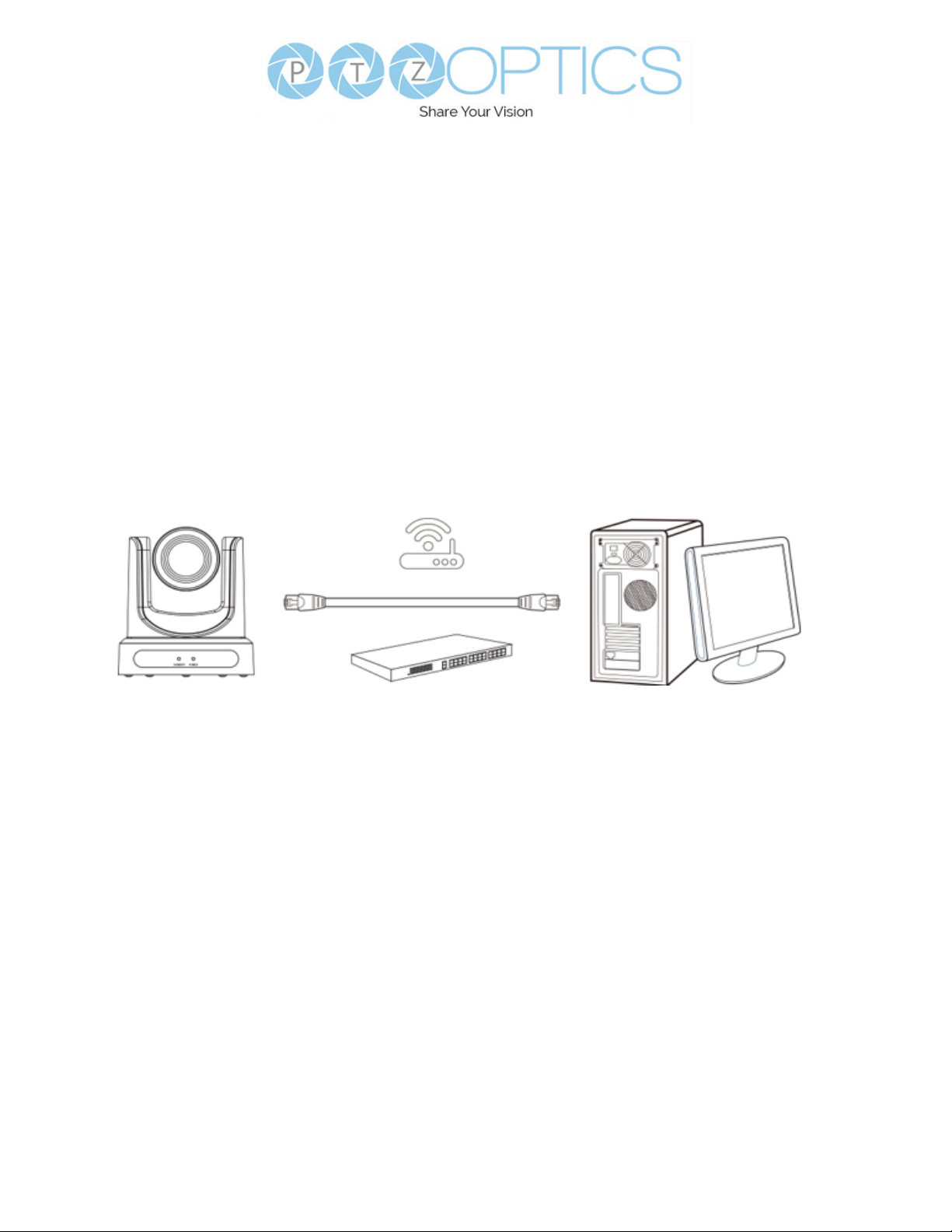
Network Connection
Operating Environment
• Operating System: Windows 7 / 8.1 / 10 / 11 Mac OS, Linux, Android
• Network Protocol: TCP/IP
• Client PC: P4 / 128M RAM / 40G HDD / , Supports scaled graphics card, Supports DirectX 8.0
or more advanced version.
Equipment Installation
1. Connect the camera to your network via a CAT5 or CAT6 cable directly to your network switch.
2. Turn on power.
3. If successful, the orange network light will illuminate and the green light will start ashing.
4.
Picture 1.2 Connections to LAN via patch cable to LAN wall jack or LAN Switch
Finding the Camera’s IP Address
The camera will automatically acquire an IP address when connected to the network. If the network
cannot assign an IP address, the camera will default to “192.168.100.88”. If you don’t know the
camera IP, please do one of the following:
• Method 1: Use a Internet browser and type in “http://ptzoptics.local/” to reach the camera’s web
interface. From there, the Network Settings page will allow you to view the camera’s network
settings.
• Method 2: Connect camera to PC with network cable, use Upgrade Tool to search for IP
address.
.
26
v1_1 rev 5-23
Page 27
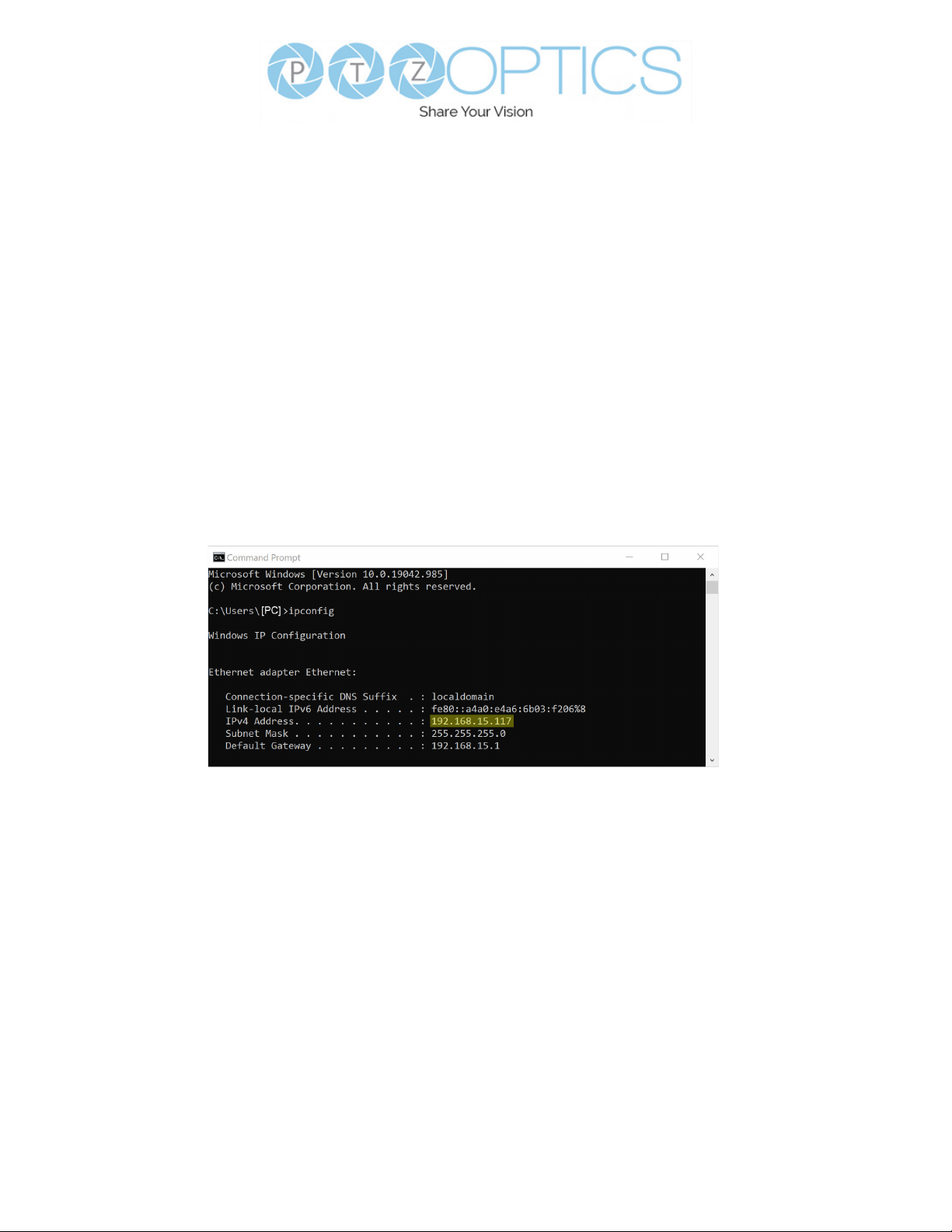
Discovering your Network Info
To discover your IP address range/scheme, Subnet Mask, Gateway, & First DNS, follow the
instructions below for Windows or Mac OS. You may need to talk with your IT department to obtain
this information.
Windows
1. Open the Start menu and type “CMD” into the search bar.
2. Once the Command Prompt is open, type in “ipcong” and press the Enter key.
3. Scroll down to the section titled “Ethernet adapter Ethernet” or “Ethernet adapter Wireless Network Connection”.
4. Locate the “IPv4 Address” in that section. This is your computers local IP address.
5. In the example above, the PC’s local address is “192.168.15.117”, making the network range
“192.168.15”.
27
v1_1 rev 5-23
Page 28
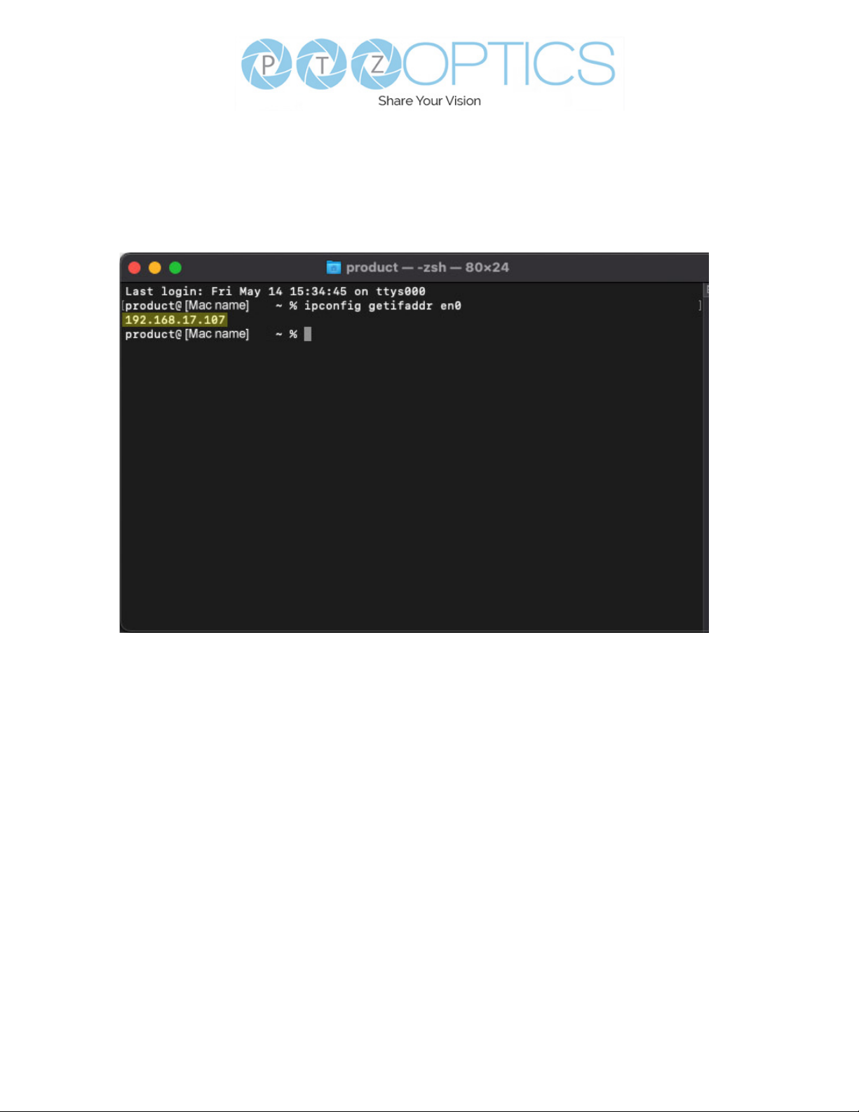
Mac
1. Open a new Finder window and go to the Applications folder.
2. Open the Utilities folder and select the Terminal program.
3. Once the Terminal program is open, type in “ipcong getifaddr en0” and press the Enter
key.
4. In the example above, the Mac’s local address is 192.168.17.107”, making the network range
“192.168.17”.
28
v1_1 rev 5-23
Page 29
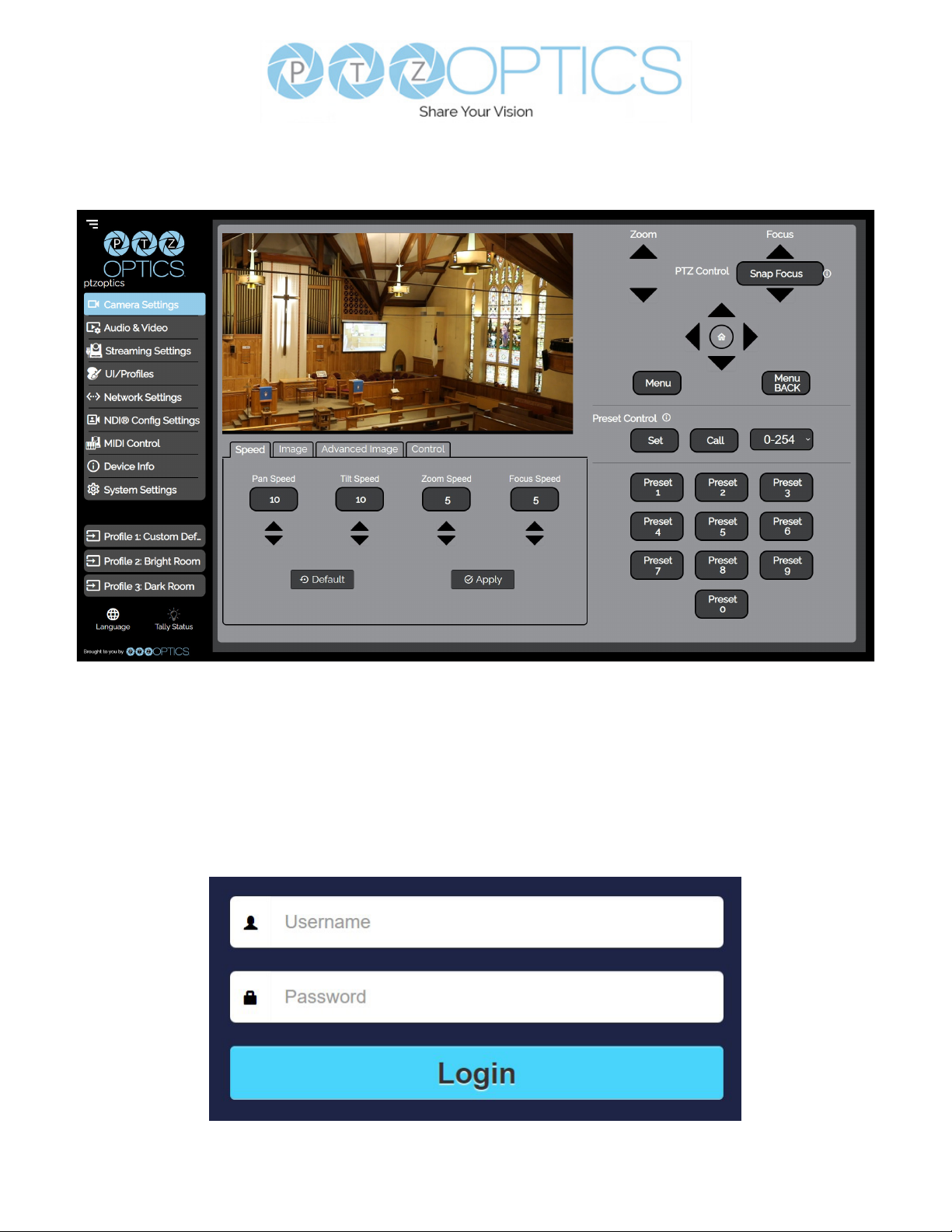
Web UI
Access Camera
1. Enter “http://ptzoptics.local/” or the camera’s IP address into a web browser.
2. Enter the username and password into the login elds. Both the username and password are
“admin” by default. You can change the login credentials on the System Settings page.
29
v1_1 rev 5-23
Page 30
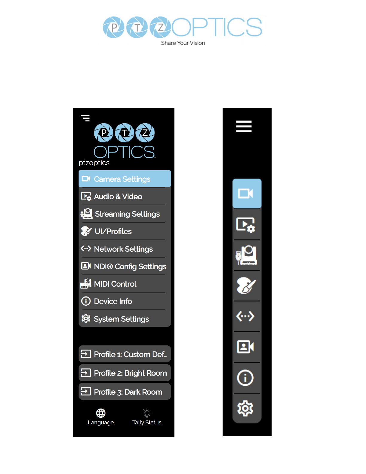
Navigation Panel
The Navigation Panel allows you to quickly and easily select the various control options for the
camera. It can be collapsed for more room on the user interface.
You can load precongured Proles to the camera by selecting the desired Prole from the Navigation
Panel.
30
v1_1 rev 5-23
Page 31
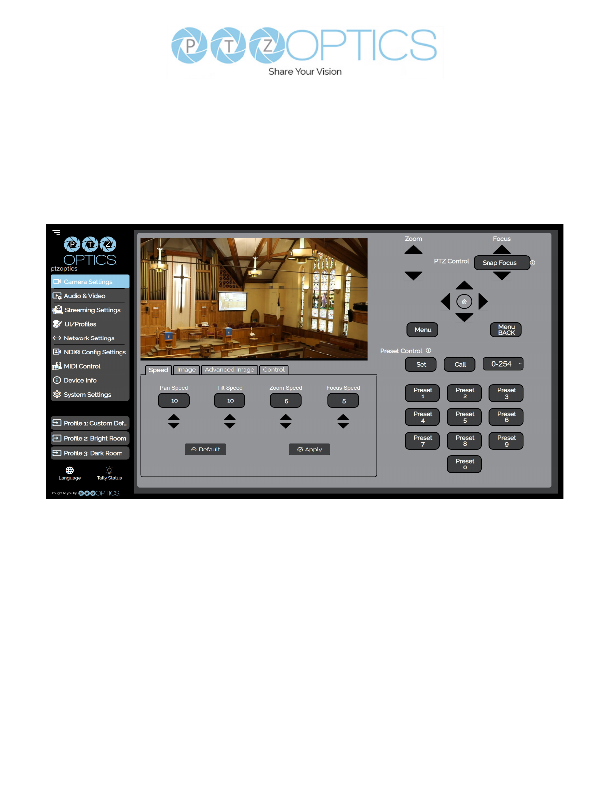
Camera Settings
The Camera Settings page accesses the PTZ Control, OSD Menu, Preset Control, Speed
settings, Image settings, Advanced Image settings, and Control settings sections.
The settings available in the Image & Advanced Image sections are also available in the camera’s
Menu. The settings are oered in the Web UI so you don’t have to open the Menu while the camera is
in use.
• The PTZ Control section allows you to Zoom & Focus the camera.
• The Menu & Menu Back buttons allow you to traverse the Menu when needed.
• The Preset Control section allow you to save and call up to 254 presets.
Ŝ The Preset 0 – 9 buttons allow you to quickly call the rst 10 presets.
• The Speed tab allows you to adjust the speed at which the camera will Zoom and Focus within the Web
UI.
31
v1_1 rev 5-23
Page 32
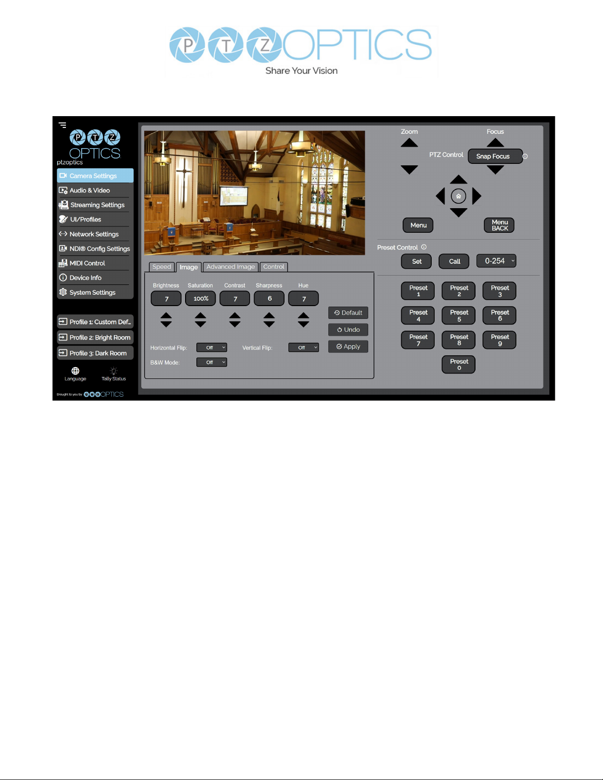
Image
• The Image tab allows you to adjust the Brightness, Saturation, Contrast, Sharpness and
Hue of the image. You can also turn on / o Horizontal or Vertical Flip and Black and White
Mode.
Ŝ You must hit the “Apply” button for these changes to take eect.
Ŝ The “Default” button will revert the Image settings to factory default.
Ŝ The “Undo” button will revert the Image settings to the last saves settings.
32
v1_1 rev 5-23
Page 33
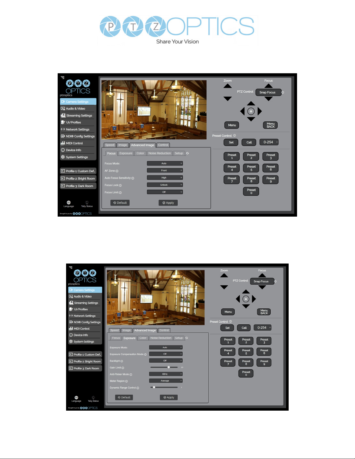
Advanced Image
• The Advance Image > Focus tab allows you to adjust the various focus settings, including Auto
Focus, AF Zone, Auto Focus Sensitivity, Focus Lock, & Focus Limit.
• The Advanced Image > Exposure tab allows you to ne tune the camera’s exposure settings to
ensure image clarity as well as ensuring the images from multiple cameras match.
33
v1_1 rev 5-23
Page 34
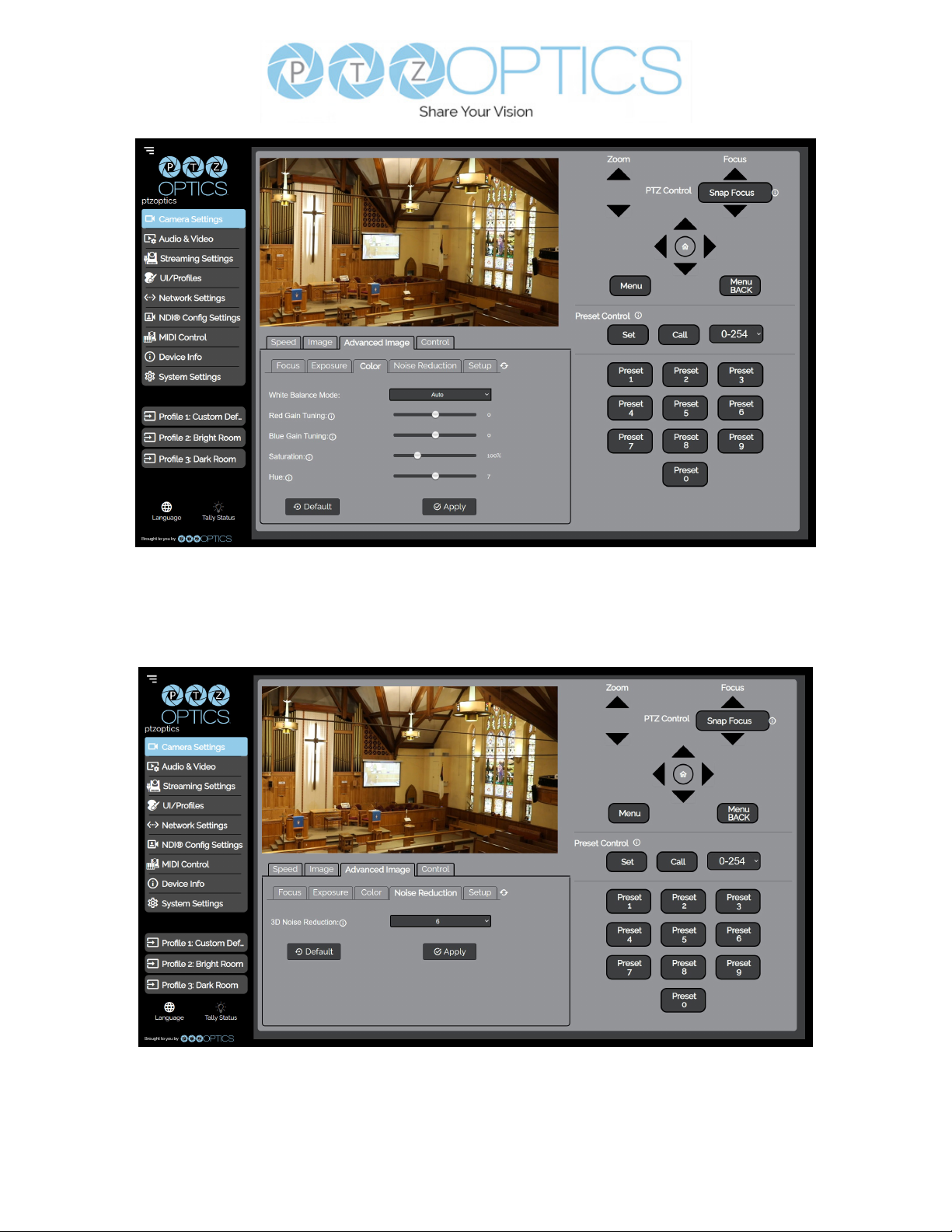
• The Advanced Image > Color tab allows you to ne tune the camera’s white balance and color
tint settings to adjust for lighting as well as ensuring images from multiple cameras match.
• The Advanced Image > Noise Reduction tab allows you to ne tune the 2D & 3D Noise
Reduction setting.
34
v1_1 rev 5-23
Page 35
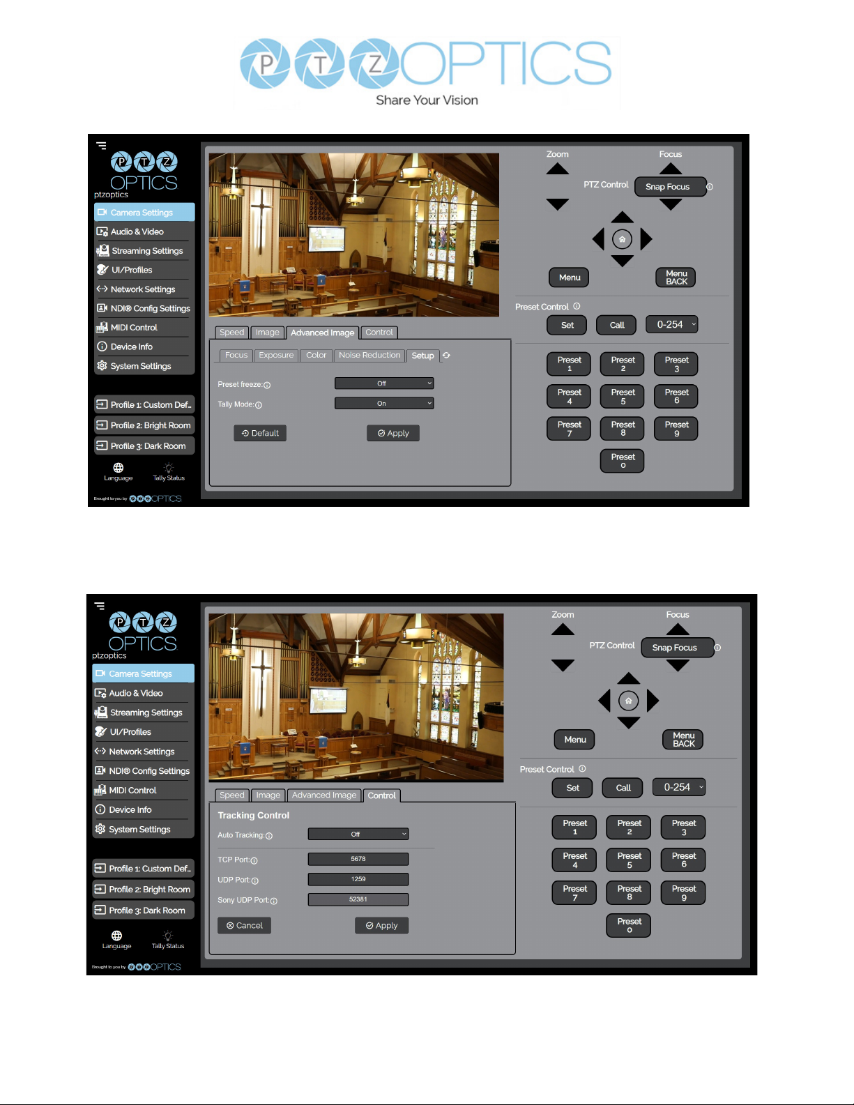
• The Advanced Image > Setup tab allows you to change the Image Style and Toggle Tally
Mode on / o.
• The Control tab allows you to access the camera’s TCP, UDP, & Sony UDP control ports.
35
v1_1 rev 5-23
Page 36
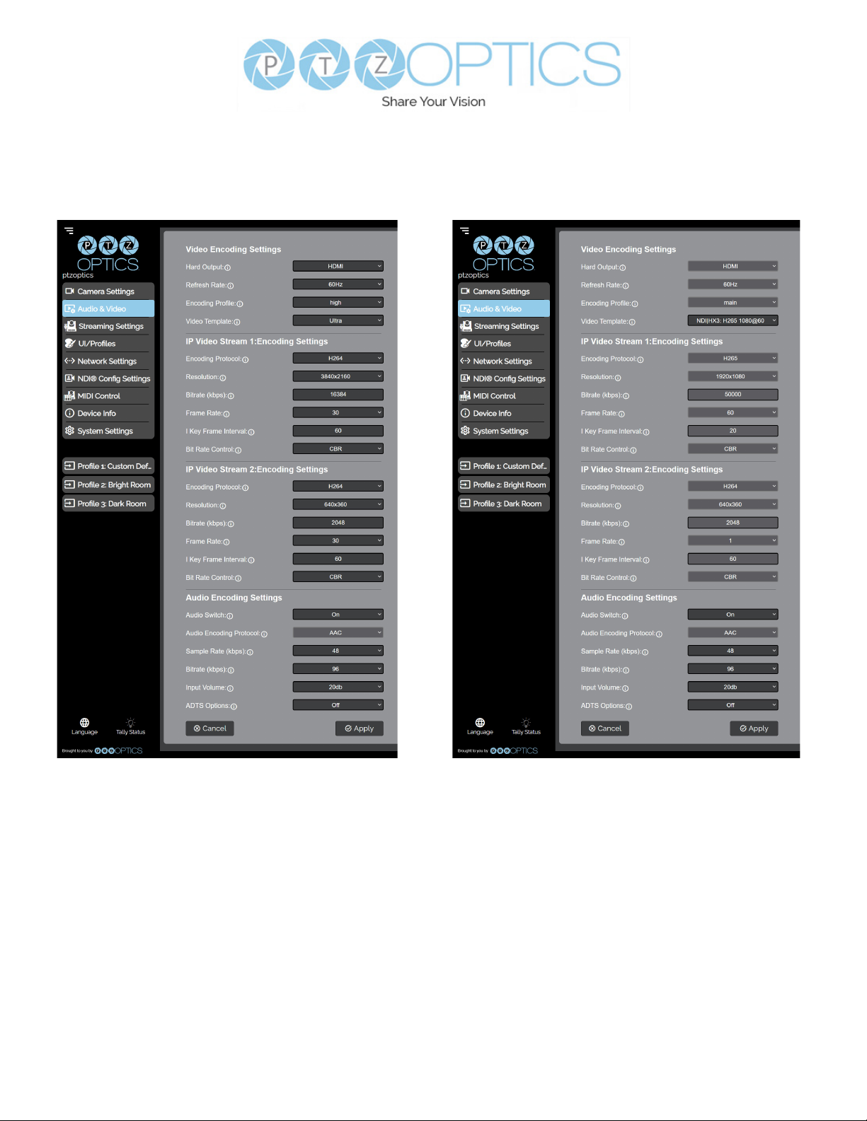
Audio & Video Settings
The Audio & Video Settings page accesses the Video Encoding Settings, IP Video Stream 1 /
Stream 2 Encoding Settings, & Audio Encoding Settings sections of the network video feeds.
• Video Encoding Settings
Ŝ Refresh Rate: Frequency adjustment for displays. Select the refresh rate for your region.
▪ Option includes: Dial Priority, 50Hz, 60Hz
Ŝ Encoding Protocol: The Encoding Prole denes the compression method and color
reproduction of the IP Stream.
▪ Options include: main, high.
Ŝ Video Template: Select from frequently used pre-congured settings. You can manually
dene these settings.
▪ Option includes: O, Ultra, High, Medium, Low, NDI|HX3 H264 1080@50, NDI|HX3
H264 1080@60, NDI|HX3 H265 1080@50, NDI|HX3 H265 1080@60 When the
NDI|HX3 templates are selected, the Refresh Rate, Encoding Prole, Encoding
Protocol, Resolution, Bitrate, Frame Rate, I Key Frame Interval, & Bit Rate Control
settings are locked.
36
v1_1 rev 5-23
Page 37

• HDMI Output: Encoding Settings
Ŝ Video Format: Dene the resolution and framerate of the HDMI output
▪ Options include: 1080p60, 1080p50, 1080p30, 720p60, 720p50
• IP Video Stream 1 & 2: Encoding Settings
Ŝ Encoding Protocol: Dene the compression method for the stream.
▪ Option includes: H264, H265, MJPEG
Ŝ Resolution: Dene the resolution of the stream.
▪ Stream 1 option includes: 3840x2160, 1920x1080, 1280x720, 1024x576, 720x480,
720x408, 640x480, 640x360
▪ Stream 2 option includes: 720x480, 720x408, 640x480, 640x360, 480x320, &
320x240
Ŝ Bitrate (kbps): Dene the bit rate of the stream in kilobits. The higher the value, the higher
the video quality at the cost of higher bandwidth.
▪ Stream 1 Range: 1 ~ 102400
▪ Stream 2 Range: 1 ~ 20480
Ŝ QFactor: Dene the Quality Factor of the stream. The higher the value, the higher the video
quality at the cost of higher bandwidth (Only available when MJPEG is selected as the
Encoding Protocol).
▪ Range: 1 ~ 99
Ŝ Frame Rate: Dene the Frame Rate of the stream.
▪ Range: 1 ~ 60
Ŝ I Key Frame Interval: Dene the I-Key Frame Interval of the stream.
▪ Range: 1 ~ 1200
Ŝ Bit Rate Control: Select whether the Bit Rate uctuates (VBR) or is static (CBR).
▪ Options include: CBR, VBR
• Audio Encoding Settings
Ŝ Audio Switch: Select whether Audio is included on the applicable video outputs.
▪ Options include: On, O
Ŝ Audio Encoding Protocol: Dene the audio compression method.
▪ Options include :AAC
Ŝ Sample Rate (kbps): Dene the amount of samples per second the audio utilizes.
▪ Options include: 44.1, 48
Ŝ Bitrate (kbps): Dene the amount of bits per second the audio utilizes in kilobits
▪ Option includes: 96, 128
Ŝ Input Volume: Dene the Input Volume of the Audio Input.
▪ Range: 0db ~ 59db
Ŝ ADTS Options: Select whether Audio Data includes timestamps.
▪ Options include: On, O
37
v1_1 rev 5-23
Page 38
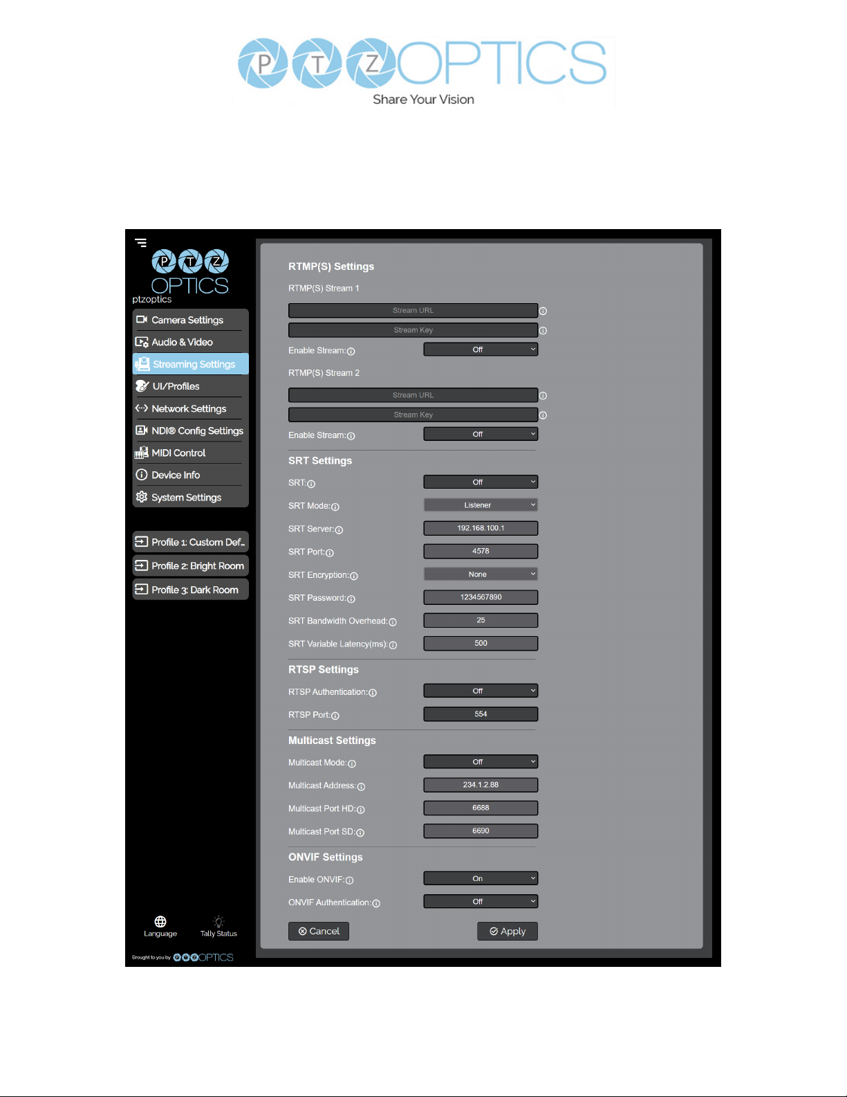
Streaming Settings
The Streaming Settings page accesses the RTMP(S) Settings, SRT Settings, RTSP Settings,
Multicast Settings, & ONVIF Settings sections.
38
v1_1 rev 5-23
Page 39

• RTMP(S) Stream 1 & 2 Settings
Ŝ RTMP(S) Stream URL: Dene the RTMP Address of the CDN you wish to stream to.
Ŝ RTMP(S) Stream Key: Dene the stream key of the CDN you wish to stream to.
Ŝ Enable Stream: Toggle the RTMP stream on or o.
• SRT Settings
Ŝ SRT: Toggle the SRT stream on or o.
Ŝ SRT Mode: Dene whether the SRT stream is pulled (Listener) from the camera, or
whether the stream must be pushed (Caller) to a server.
Ŝ SRT Server: Dene the Server IP address. This is only used in Caller mode.
Ŝ SRT Port: The SRT Port is how you reach the SRT video feed of your camera.
Ŝ SRT Encryption: Toggle SRT Encryption on or o.
Ŝ SRT Password: Dene the SRT password when utilizing SRT Encryption
Ŝ SRT Bandwidth Overhead: SRT Bandwidth is a percentage that you assign that helps
determine the total bandwidth that the SRT stream will use up. This percentage should not
exceed 50%, and is set to 25% by default.
Ŝ SRT Variable Latency(ms): Dene the maximum buer size for maintaining SRT packets
from the camera to the destination.
• RTSP Settings
Ŝ RTSP Authentication: Toggle RTSP Authorization on or o.
Ŝ RTSP Port: The RTSP Port is how you reach the RTSP video feed(s) of your camera.
• Multicast Settings
Ŝ Multicast Mode: Toggle Multicast on or o. WARNING! Only use this setting with a network
congured for Multicast.
Ŝ Multicast Address: Dene the Multicast Address. Recommended format:
234.1.2.[camera IP address last octet]
Ŝ Multicast Port: The Multicast Port is how you reach the stream through RTP Multicast.
• ONVIF Settings
Ŝ Enable ONVIF: Toggle ONVIF control on or o
Ŝ ONVIF Authentication: Toggle ONVIF Authentication on or o
39
v1_1 rev 5-23
Page 40
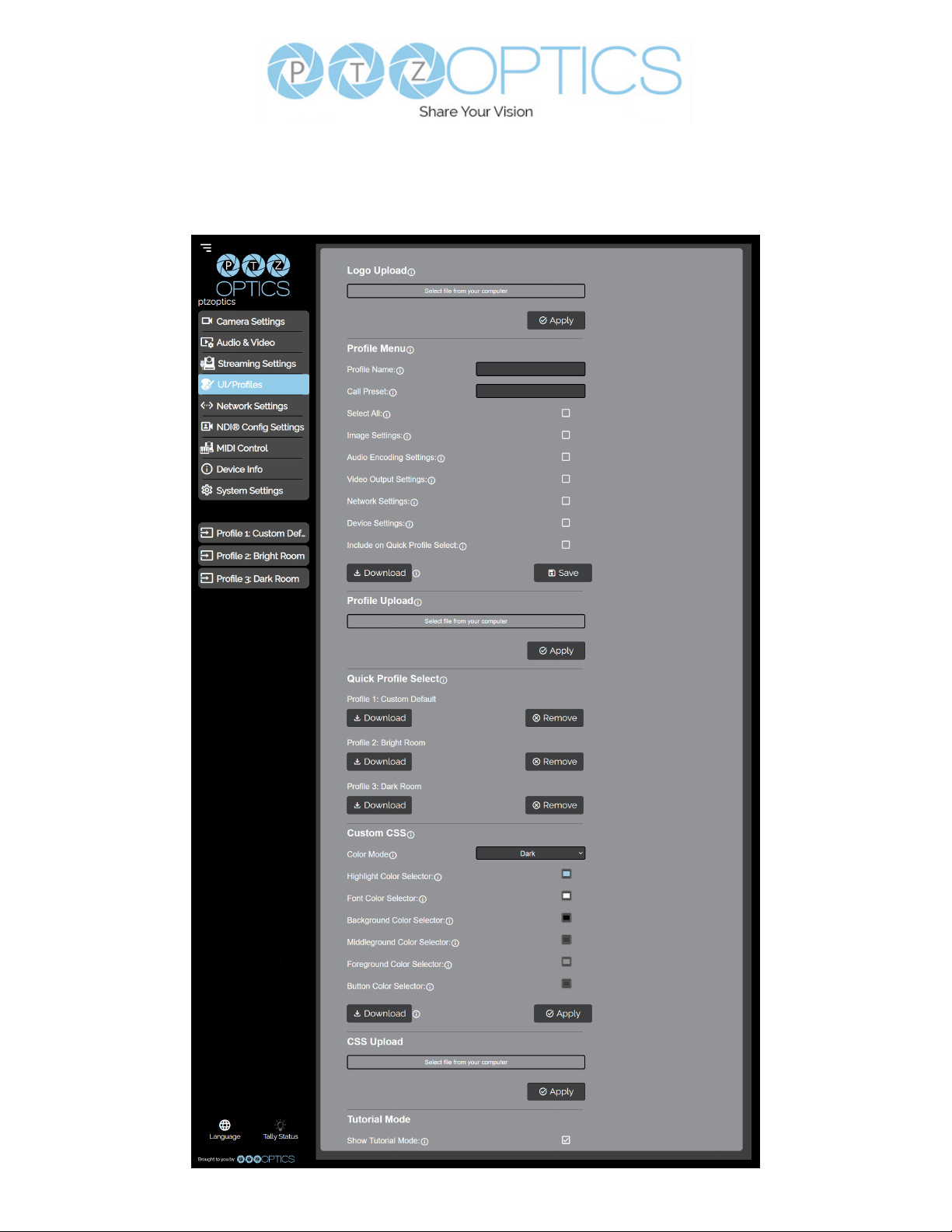
UI / Profiles
The UI / Proles page accesses the Logo Upload, Prole Conguration, Quick Proles,
Custom CSS Conguration, & Tutorial Mode sections.
40
v1_1 rev 5-23
Page 41

• Logo Upload
Ŝ Upload File: Browse your PC for an image le you’d like to upload to the camera’s web
interface. The resolution of this logo should be 2500x1000 and PNG or JPG type le.
• Prole Menu
Ŝ Prole Name: Give your Prole a unique name so you can easily remember.
Ŝ Call Preset: Select a preset to be called when the Prole is loaded. This eld is optional.
Ŝ Select All: Select all of the below options in the Prole Menu section.
Ŝ Image Settings: Select whether the Image Settings on the Camera Settings page are
stored in the Prole.
Ŝ Audio Encoding Settings: Select whether the Audio Settings on the Audio & Video
Settings page are stored in the Prole. This will require a camera reboot when loaded.
Ŝ Video Output Settings: Select whether the Video Settings on the Audio & Video Settings
page are stored in the Prole. This will require a camera reboot when loaded.
Ŝ Network Settings: Select whether the settings on the Network Settings page are
stored in the Prole. This will require a camera reboot when loaded.
Ŝ Device Settings: Select whether the settings on the Device Info page are stored in the
Prole. This will require a camera reboot when loaded.
Ŝ Include on Quick Prole Select: Select whether the Prole is displayed in the Quick
Prole Select section on the Navigation Panel.
Ŝ Download: Download the prole from the Prole Menu section.
Ŝ Save: Save the congured Prole. The Include on Quick Prole Select checkbox needs to
be checked in order to save the Prole to the camera.
• Prole Upload
Ŝ Upload File: Upload a saved Prole from your computer to the camera.
• Quick Prole Select
Ŝ Download Button: Download the selected Prole to your computer.
Ŝ Remove Button: Remove the selected Prole from the camera.
Ŝ Custom CSS
Ŝ Color Mode: Select the color mode of the Web UI. Custom allows you to dene your own
colors.
Ŝ Highlight Color Selector: Dene the color that buttons glow while hovering over or
pressing the buttons.
Ŝ Font Color Selector: Dene the font color.
Ŝ Background Color Selector: Customize the background color of the Web UI.
Ŝ Middleground Color Selector: Customize the middleground color of the Web UI.
Ŝ Foreground Color Selector: Customize the foreground color of the Web UI.
Ŝ Button Color Selector: Customize the button background and text eld color of the Web
UI.
▪ The colors can be dened by using the eyedropper tool, decimal code, HSL code, or
hex code.
• CSS Upload
Ŝ Upload File: Upload a saved Custom CSS le from your computer to the camera.
• Tutorial Mode
Ŝ Show Tutorial Mode: While checked, the Information Symbols and associated text will be
available, giving a description of each available setting.
41
v1_1 rev 5-23
Page 42
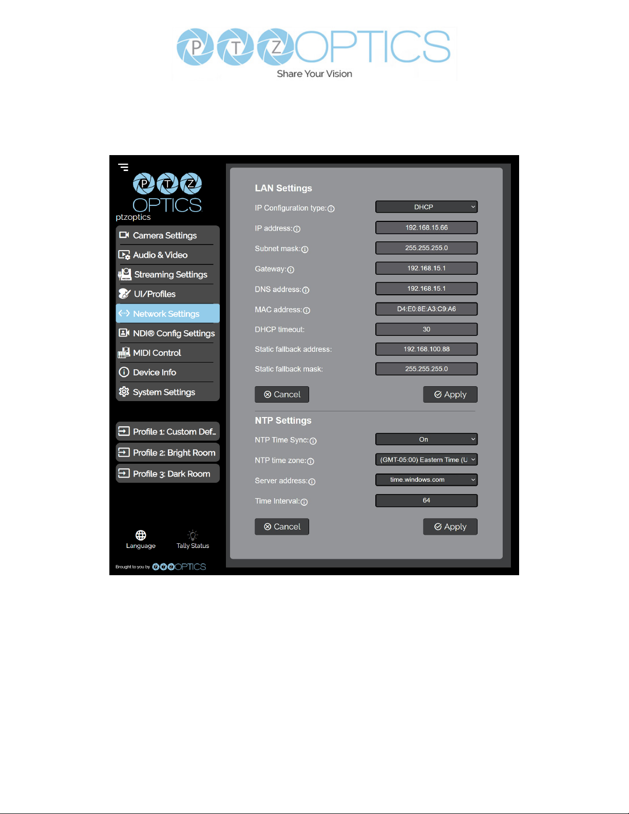
Network Settings
The Network Settings page accesses the LAN Settings & NTP Settings sections.
42
v1_1 rev 5-23
Page 43

• LAN Settings
Ŝ IP Conguration Type: Select whether the camera automatically congured the network
settings (DHCP) or whether you manually congure the network settings (Static).
Ŝ IP Address: The IP address is a unique address the network uses to connect and congure
the camera.
Ŝ Subnet Mask: The Subnet Mask is a set of numbers that denes how large your network
is.
Ŝ Gateway: The Gateway is the address associated with your router to connect to the
internet.
Ŝ DNS Address: The DNS address is a unique IP address the camera will query when trying
to reach a specic website.
Ŝ MAC Address: The MAC Address is a unique address the Ethernet port utilizes to
communicate with the network. You can not change this address.
Ŝ DHCP Timeout: DHCP Timeout is the amount of time the camera will try to acquire an IP
address through DHCP. After this time, the camera will revert to the Static Fallback Address
& Static Fallback Mask. You can not change this timeout.
Ŝ Static Fallback Address: Static Fallback Address is the IP address the camera will revert
to if one can’t be acquired automatically. You can not change this address.
Ŝ Static Fallback Mask: Static Fallback Mask is the Subnet Mask the camera will revert to if
one can’t be acquired automatically. You can not change this subnet mask.
• NTP Settings
Ŝ NTP Time Sync: Toggle Network Time Protocol (NTP) on or o.
Ŝ NTP Time Zone: Select your time zone.
Ŝ Server Address: Dene the NTP Server Address you wish to utilize.
Ŝ Time Interval: Dene how frequently NTP queries the server (in seconds).
43
v1_1 rev 5-23
Page 44
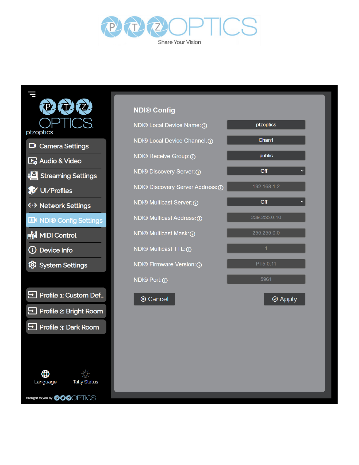
NDI® Config Settings
The NDI Cong Settings page accesses the camera’s NDI settings.
44
v1_1 rev 5-23
Page 45

• NDI Cong
Ŝ NDI Local Device Name: The Local Device Name is the name you assign to your NDI
device.
Ŝ NDI Local Device Channel: The Local Device Channel is the video feed that you assign to
your NDI Local Device Name.
Ŝ NDI Receive Group: The Receive Group denes which devices on a LAN can view the
NDI sources. The camera and computer’s Receive Group must match in order to view the
NDI source. Your camera can be part of multiple groups.
Ŝ NDI Discovery Server: Toggle the NDI Discovery Server connection on or o. The
Discovery Server handles discovering and distributing NDI sources more reliably across
your LAN.
Ŝ NDI Discovery Server Address: Dene the Discovery Server IP address.
Ŝ NDI Multicast Server: Toggle the NDI Multicast Server on or o. NDI Multicast allows for a
single NDI source to be viewed across multiple PCs more reliably. WARNING! Only use this
setting with a network congured for Multicast.
Ŝ NDI Multicast Address: Dene the NDI Multicast Server Address.
Ŝ NDI Multicast Mask: Dene the Multicast Subnet Mask.
Ŝ NDI Multicast TTL: Dene how frequently Multicast Time to Live (TTL) queries (in
minutes).
Ŝ NDI Firmware Version: The NDI Firmware version currently running on the camera.
Ŝ NDI Port: The NDI Port is how you reach the NDI feed of your camera.
For more information on how to utilize the NDI® Discovery Server, please see :
https://help.ptzoptics.com/en/support/solutions/articles/13000086877-ndi-discovery-server
NewTek®, NDI®, NDI® 4, & NDI®|HX are all registered trademarks by Vizrt Group®.
45
v1_1 rev 5-23
Page 46
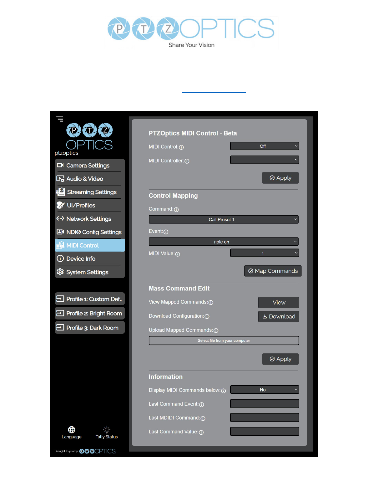
MIDI Control
The MIDI Control page accesses the PTZOptics MIDI Control, Control Mapping, Mass
Command Edit & Information sections. The MIDI Control page can be reached by accessing the
HTTPS version of the camera’s web interface. (https://[Camera IP]/). The page must remain open for
MIDI Control tofunction.
46
v1_1 rev 5-23
Page 47

• PTZOptics MIDI Control
Ŝ MIDI Control: Toggle MIDI Control on or o.
Ŝ MIDI Controller: Select a MIDI Controller that’s connected to your PC.
• Control Mapping
Ŝ Command: What function you’d like the camera to perform.
Ŝ Event: How you would like the trigger the command to be sent.
Ŝ MIDI Value: The value associated with the button / dial / knob / etc. on the MIDI Controller.
• Mass Command Edit
Ŝ View Mapped Commands Button: View the commands currently mapped to the camera.
Ŝ Download Conguration: Download the commands currently mapped to the camera.
Ŝ Upload Mapped Commands: Upload a list of mapped MIDI commands to the camera.
• Information
Ŝ Display MIDI Commands below: Select whether the camera displays the commands
being sent from the MIDI Controller. This is typically used when Control Mapping.
Ŝ Last Command Event: The most recent MIDI Event the Controller sent.
Ŝ Last MIDI Command: The most recent MIDI Command the Controller sent.
Ŝ Last Command Value: The most recent MIDI Value the Controller sent.
47
v1_1 rev 5-23
Page 48
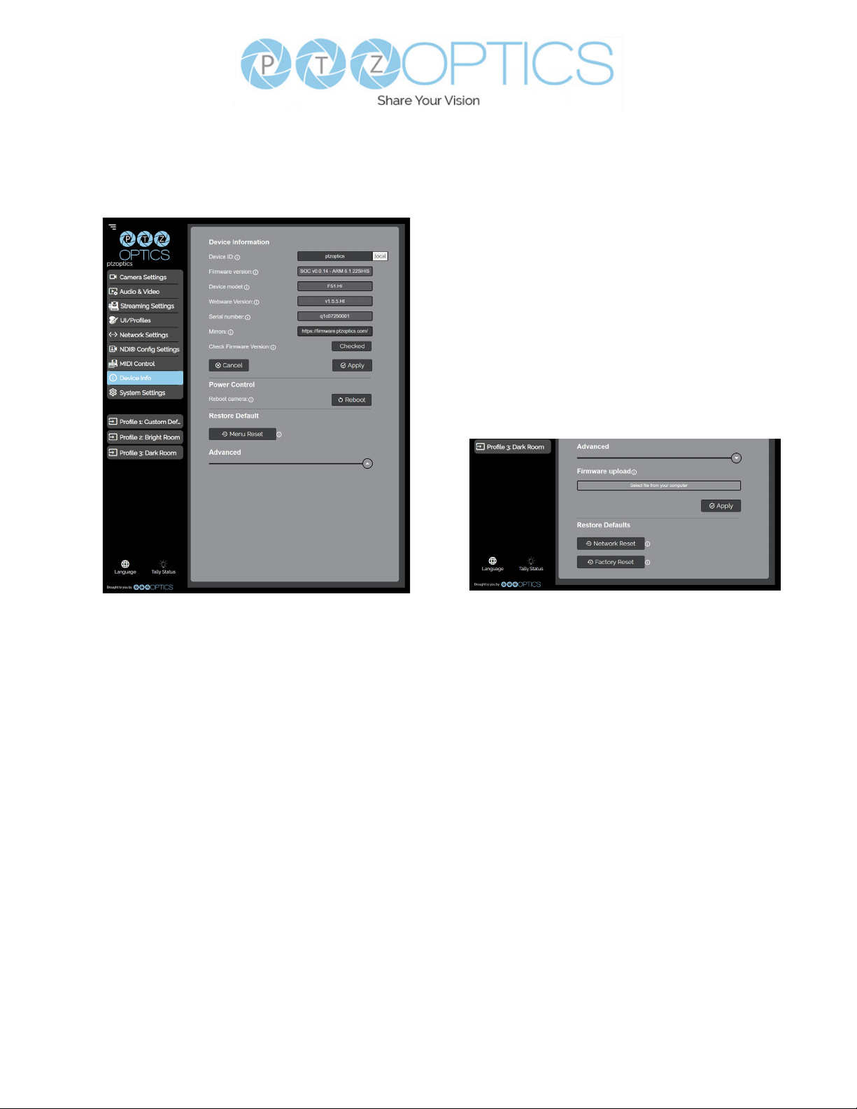
Device Info
The Device Info page accesses the Device Information, Power Control, Restore Default &
Firmware Upload sections.
• Device Information
Ŝ Device ID: Dene the camera’s Device ID to clearly designate which camera you’re
interacting with. The Device ID is displayed at the top left of the Navigation Panel and
anything that queries the camera’s name.
Ŝ Firmware Version: The Firmware Version displays the rmware le currently running on
the camera.
Ŝ Device Model: The Device Model is a eld that PTZOptics uses to designate the camera.
Ŝ Webware Version: The Webware Version is the version of the web interface.
Ŝ Serial Number: The camera’s serial number.
Ŝ Mirrors: Dene a server address for acquiring the latest PTZOptics rmware les. By
default, the camera will query PTZOptics’ at https://rmware.ptzoptics.com/.
Ŝ Check Firmware Version Button: Check to see if your camera is running the latest
rmware from the Firmware Update Server.
• Power Control
Ŝ Reboot Camera: Reboot / Power Cycle the camera.
• Restore Default (Basic)
Ŝ Menu Reset: Reset the camera’s non-network settings to factory default.
• Firmware Upload
Ŝ File Upload: Select a rmware le from your PC to upload to the camera.
• Restore Default (Advanced)
Ŝ Network Reset: Reset the camera’s network settings to factory default.
Ŝ Factory Reset: Reset the camera’s network and non-network settings to factory default.
48
v1_1 rev 5-23
Page 49
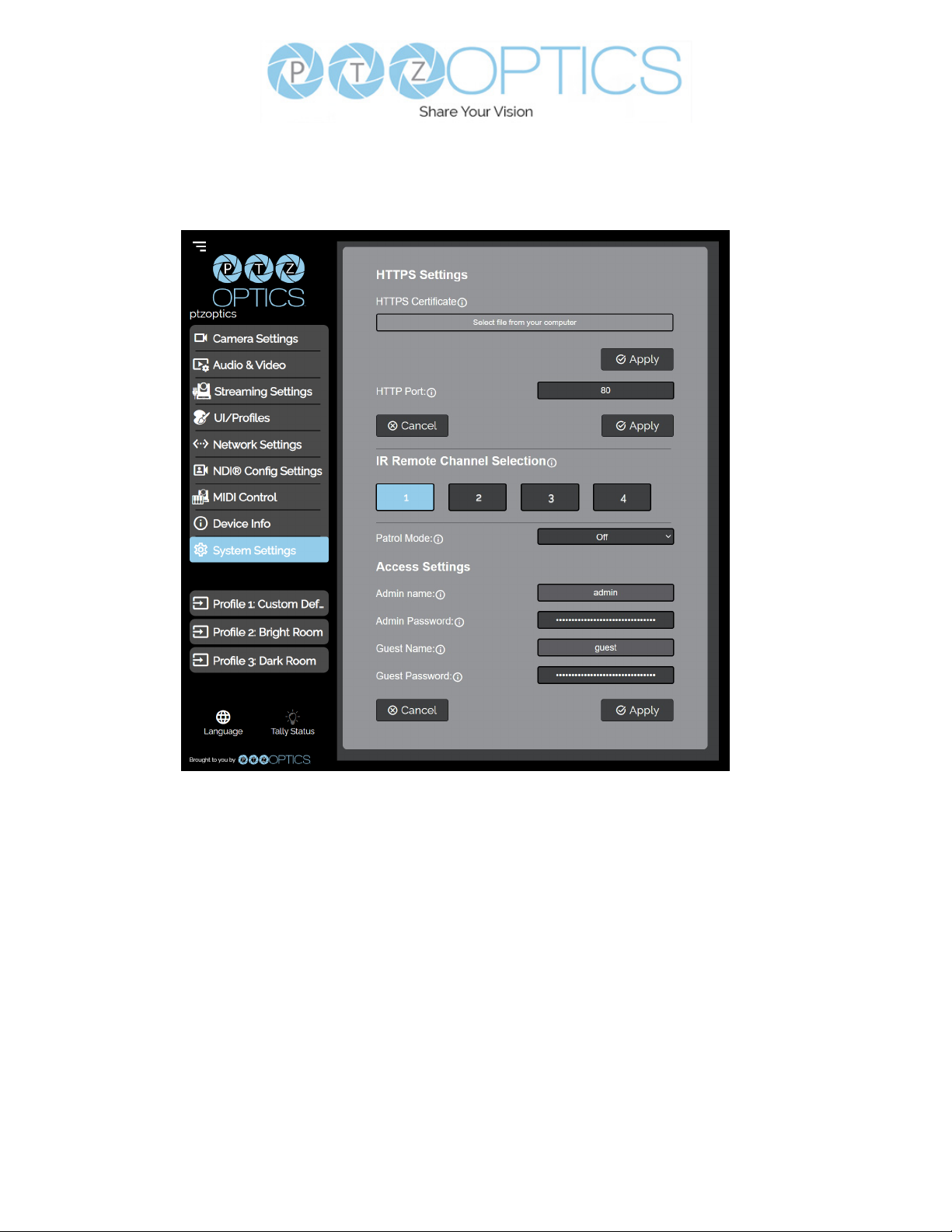
System Settings
The System Settings page accesses the HTTPS Settings, IR Remote Channel Selection &
Access Settings sections.
• HTTPS Settings
Ŝ HTTPS Certicate: Upload a HTTPS Certicate from your computer.
Ŝ HTTP Port: The HTTP Port is how you reach the web interface of your camera
(http://[Camera IP]:[port]/)
• IR Remote Channel Selection
Ŝ 1 – 4 Button: Dene the communication channel the camera utilizes with the remote
control. This allows you to easily use multiple cameras with a single IR remote.
• Access Settings
Ŝ Admin Name: Administrator username login. This username can not be changed.
Ŝ Admin Password: Administrator password. If you desire to change the password, all
letters, numbers, and specically “!@#$%^&*()” can be used, up to 15 characters. Please
note the circles in the eld are encrypted and do not reect the password saved on the
camera.
Ŝ Guest Name: Guest username login. This username can not be changed.
Ŝ Guest Password: Guest password. If you desire to change the password, all letters,
numbers, and specically “!@#$%^&*()” can be used, up to 15 characters. Please note the
circles in the eld are encrypted and do not reect the password saved on the camera.
49
v1_1 rev 5-23
Page 50

Maintenance and Troubleshooting
Camera Maintenance
• If the camera will not be used for a long time, power o the camer.a
• Use a soft cloth or lotion-free tissue to clean the camera body.
• Use a soft, dry, lint-free cloth to clean the lens. If the camera is very dirty, clean it with a diluter
neutral detergent. DO not use any type of solvert or harsh detergent which may damage the
surface.
Unqualified Applications
• Avoid shooting at particularly bright objects, such as sunlight, lights, etc. for a long period of
time.
• Do not operate close to powerful electromagnetic radiation, such as TV or radio transmitters, etc.
Troubleshooting
• No image
1. Check whether the power cord is connected, voltage is OK, & Power LED is lit.
2. Check whether the camera can “self-test” after startup. You can also press [*] > [#] >
3. [Auto Focus] on the IR remote to trigger the camera to perform the startup dance on repeat.
4. If using SDI or HDMI, check that the desired connection is selected to output video. You
can select the desired connection from the OSD Menu or through the Web Interface.
5. Check that the video cable is connected correctly to th destination device
• Image is shaky or vibrating
1. Check whether the camera is mounted solidly or sitting on a steady horizontal and level
surface.
2. Check the building and any supporting furniture for vibration. Ceiling mounts are often
aected by building vibration more than wall mounts.
3. Any external vibration that is aecting the camera will be more apparent when zoomed in.
• Abnormal display of image
1. Check the resolution dial on the back of the camera. Verify that the resolution and refresh
rate is supported by your destination device.
2. If using SDI, check that the SDI level is set to the desired level.
• Image settings are changing on their own
1. The cameras have a feature called “Preset 2.0” where many of the Exposure, White Balance, and Image settings are saved with each preset. When a preset is called, the saved
Exposure, White Balance, and Image settings are then loaded.
50
v1_1 rev 5-23
Page 51

Control
• IR remote controller does not control the camera
1. Does one of the four “Camera Select” buttons at the top of the remote light up when you
press any of the buttons?
▪ If not, change the batteries in the remote.
2. Check that the remote and camera are on the same IR channel. The “Camera Select”
buttons will light up with the selected IR channel when a button is pressed. You can
change the camera’s IR channel by accessing the System Settings of the web interface.
3. Try removing other sources of IR interface (sunlight, uorescent lighting, etc.)
• Serial communication does not control the camera
1. Verify that the RS232 / RS485 cable is connected correctly and using the proper pinout.
Verify the communication settings of the control software / device (e.g. joystick).
2. Verify that the communication port on the controlling device is active (e.g. Com port on
3. PC).
4. Verify that the communication settings in the camera’s OSD Menu match the
communication settings of the controlling software / device.
• IP communication does not control the camera
1. Verify that the camera and controlling device are on the same LAN with unique IP
addresses.
2. Verify that the controlling device is using the appropriate control port for the protocol.
The default control ports are as follows: TCP 5678, UDP 1259, Sony UDP: 52381, NDI:
5961
If you need further assistance, please contact our support team at https://help.ptzoptics.com/support/
login/.
51
v1_1 rev 5-23
 Loading...