

Page 1
9160 G2
Wireless Gateway
User Manual
November 24, 2006 Part No. 8100117.A
ISO 9001 Certified
Quality Management System
Page 2

© Copyright 2006 by Psion Teklogix Inc., Mississauga, Ontario
This document and the informati on i t cont ains is the property of Psion Teklogix Inc.,
is issued in strict confidence, and is not to be reproduced or copied, in whole or in
part, except for the sole purpose of promoting the sale of Psion Teklogix manufactured goods and services. Furthermore, this document is not to be used as a basis for
design, manufacture, or sub-contract, or in any manner detrimental to the intere sts of
Psion Teklogix Inc.
All trademarks are the property of their respective holders.
Page 3
Return-To-Factory Warranty
Psion T eklog ix Inc. provi des a return to factory warranty on t his product for a period
of twelve (12) months in accordance with the Statement of Limited Warranty and
Limitation of Liabili ty prov ided at www.psionteklogix.com/warranty. (If you are not
already a member of Teknet and you attempt to view this warranty, you will be
asked to register. As a member of Teknet, you will have access to helpful information about your Psion Teklogix products at no charge to you.) In some regions, this
warranty may exceed this period. Plea se c ontact your loc al Psio n Teklogix office for
details. For a list of offices, see Appendix A: “Support Services And Worldwide
Offices”. The warranty on Psion Teklogix manufactured equipment does not extend
to any product that has been tampered with, altered, or repaired by any person other
than an employee of an authorized Psion Teklogix service organization. See Psion
Teklogix terms and conditions of sale for full details .
Important: Psion Teklogix warranties take effect on the date of shipment.
Service
Psion Teklogix provides a complete range of product support services to its customers. For detailed information, please refer to Appendix A: “Support Services And
Worldwide Offices”. This section als o provi des informat ion abou t acce ssing s upport
services through the Psion Teklogix web site.
Waste Electrical and Electronic Equipment (WEEE) Directive 2002/96/EC
This Product, and its accessories, comply with the requirements of the Waste Electrical and Electronic Equipment (W EEE) Directive 2002/96/EC. If your end-of-life
Psion Teklogix product or accessory carries a label as shown here, please contact
your local country represe ntat ive for det ail s on how to arrange recycling.
For a list of internati onal subsi diaries, please go to:
www.psionteklogix.com/public.aspx?s=us&p=Contacts.
Restriction On Hazardous Substances (RoHS) Directive 2002/95/EC
What is RoHS?
The European Union has m andated th at high environm ental standards b e met in the
design and manufacture of electronic and electrical products sold in Europe, to
reduce hazardous substances from entering the environment. The “Restriction on
Hazardous Substances D irective (RoHS)” prescribes the maximum trac e levels of
Page 4

lead, cadmium, mercury, hexavalent chromium, and flame retardants PBB and PBDE
that may be contained in a product. O nly produ cts meeting the se high env ironmenta l
standards may be “placed on the market” in EU member states after July 1, 2006.
RoHS Logo
Although there is no legal requirement to mark RoHS-compliant products, Psion
Teklogix Inc. indicates its compliance with the di re ctive as follows:
The RoHS logo located either on the back of the product or under neat h t he battery in
the battery compartment (or on a related accessory such as the charger or docking
station) signifies that the product is RoHS-compliant as per the EU directive. Other
than as noted below, a Psion Teklogix product that does not have an accompanying
RoHS logo signifies that i t was pla ced on t he EU market prior to July 1, 2006, and is
thereby exempt from the direct ive .
Note: Not all accessories or peripherals will have a RoHS logo due to physical
space limitations or as a result of their exempt status.
Disclaimer
Every effort has been made to make this mate rial com plete , accurate , and up-to-da te.
In addition, changes are periodically added to the information herein; these changes
will be incorporated into n ew edi tions of the publication.
Psion Teklogix Inc. reserves the right to make improvements and/or changes in the
product(s) and/or the program(s) described in this document without notice, and
shall not be responsible for any damages, including but not limited to consequential
damages, caused by reliance on the material presented, including but not limited to
typographical errors.
Page 5

TABLE OF CONTENTS
Approvals and Safety Summary..........................xiii
Chapter 1: Introduction
1.1 About This Manual.......................... ....3
1.2 Online Help Fe atures, Supported Browsers, And Limitat io ns........6
1.3 Text Conventions . . .............................7
1.4 Overview Of The 9 160 G2 Wireless Gateway ................7
1.4.1 Radios...................................8
1.4.2 Access Point Functions . . . .......................9
1.4.3 Base Station Functions................ ...... ....9
1.5 Features and Benefits.............................10
1.5.1 IEEE Standards Support And Wi-Fi Compliance. . . ..........10
1.5.2 Wireless Features.............................10
1.5.3 Security Features.............................11
1.5.4 Out-of-the-Box Guest Interface......................12
1.5.5 Clustering And Auto-Management....................12
1.5.6 Networking................................13
1.5.7 SNMP Support . .............................13
1.5.8 Maintainability..............................14
1.6 What’s Next?....................... ...... ....14
Chapter 2: Installation Requirements
2.1 Choosing The Right Location........................17
2.1.1 Environment................................17
2.1.1.1 9160 G2 Wireless Gateway ......................17
2.1.2 Maintenance................................18
2.1.3 Radios...................................18
2.1.4 Power And Antenna Cables........................18
Psion Teklogix 9160 G2 Wireless Gateway User Manual i
Page 6

Contents
2.1.4.1 Power................................18
2.1.4.2 Antennas...............................19
2.2 Connecting To External Devices......................21
2.2.1 Ports...................................21
2.2.2 LAN Installation: Overview.......................21
2.2.3 LAN Installation: Ethernet........................22
2.2.3.1 Ethernet Cabling...........................22
2.2.4 Status Indicators (LEDs).........................22
2.2.5 Connecting A Video Display Terminal.................23
2.3 Changing The Configuration With A Web Browser............23
Chapter 3: PreLaunch Checklist
3.1 The 9160 G2 Wireless Gateway . . . ...................27
3.1.1 Default Settings For The 9160 G2 Wireless Gateway..........27
3.1.2 What The Access Point Does Not Provi de . . . ............30
3.2 Administrator’s Computer .........................30
3.3 Wireless Client Computers.........................31
3.4 Understandi ng Dynamic And S tat ic IP Address ing On The 9160 G2 Wireless
Gateway...................................33
3.4.1 How Does The Access Point Obtain An IP Addres s At Startup? ....33
3.4.2 Dynamic IP Addressing ...... ...................33
3.4.3 Static IP Addressing...........................34
3.4.4 Recovering An IP Address........................34
Chapter 4: Quick Steps For Setup And Launch
4.1 Unpack The 9160 G2 Wireless Gateway ..................37
4.1.1 9160 G2 Wirel ess Gateway Hardware And Ports ............37
4.1.2 What’ s Inside The 9160 G2 W ire less Gateway?. ............38
4.2 Connect The Access Point To Network And Power............38
4.2.1 A Note About Setting Up Connections For A Gue st Ne twork .....40
4.2.1.1 Hardware Connecti ons For A Guest VLAN. ............40
4.3 Power On The Access Point ........................40
4.4 Log On To The Administration Web Pages.................41
4.4.1 Viewing Basic Settings For Access Points................41
ii
Psion Teklogix 9160 G2 Wireless Gateway User Manual
Page 7

Contents
4.5 Configure ‘Basic Settings’ And Start The Wireless Network........42
4.5.1 Default Configuration...........................43
4.6 What’s Next?....................... ...... ....43
4.6.1 Make Sure The Access Point Is Connected To The LAN.........43
4.6.2 Test LAN Connectivity With W ir el ess Cl ien ts ..............44
4.6.3 Secure And Fine-tune The Access Poi nt Usi ng Advanced Features . . .44
Chapter 5: Configuring Basic Settings
5.1 Navigating To Basic Settings.........................47
5.2 Review / Descr ibe The Access Point.....................48
5.3 Provide Network Settings ... ....... ...... ..........49
5.4 Update Basic Settings ............................50
5.5 Summary Of Settings.............................50
5.6 Basic Sett ings For A Standalone Access Point................51
5.7 Your Network At A Glance: Understanding Indicator Icons.........51
Chapter 6: Managing Access Points & Clusters
6.1 Overview...................................55
6.2 Navigating To Access Points Management . ................55
6.3 Understanding Clustering ..........................56
6.3.1 What Is A Cluster?............................56
6.3.2 How Many APs Can A Cluster Support? . ................56
6.3.3 What Kinds Of APs Can Cluster Together?................56
6.3.4 Which Settings Are Shared As Part Of The Clu ste r Conf igur ati on And
Which Are Not?.......................... ....57
6.3.4.1 Settings Shared In The Cluster Configuration............57
6.3.4.2 Settings Not Shared By The Cluster.................58
6.3.5 Cluster Formation...... ....... ................58
6.3.6 Cluster Size And Membership ......................58
6.3.7 Intra-Cluster Security ...........................59
6.4 Understandi ng Access Point Settings ....................59
6.4.1 Modifying The Location Description...................60
6.4.2 Setting The Cluster Name.........................60
6.5 Starting Clustering..............................61
Psion Teklogix 9160 G2 Wireless Gateway User Manual iii
Page 8

Contents
6.6 St opping Clustering .............................61
6.7 Navigating To Configuration Informati on For A Speci fi c AP And Ma nagi ng
Standalone APs...............................62
6.7.1 Navigating To An AP By Using Its IP Address In A URL.......62
Chapter 7: Managing User Accounts
7.1 Overview..................................65
7.2 Navigating To User Management For Clustered Acc ess Points ......66
7.3 Viewing User Accounts...........................66
7.4 Adding A User...............................67
7.5 Editing A User Account...........................68
7.6 Enabling And Di sabl ing Us er Acc ount s ..................68
7.6.1 Enabling A User Account........................69
7.6.2 Disabling A User Account........................69
7.7 Removing A User Account.........................69
7.8 Backing Up And Restoring A User Database................69
7.8.1 Backing Up The User Database.....................69
7.8.2 Restoring A User Database From A Bac kup Fi le ............70
Chapter 8: Channel Management
8.1 Navigating To Channel Management....................73
8.2 Understanding Channel Management....................73
8.2.1 How It Works In A Nutshell.......................74
8.2.2 For The Curious: More About Overlappi ng Channels . . . ...... 74
8.2.3 Example: A Network Before And After Channel Management.....74
8.3 Configuring And Viewing Channel Management Settings.........76
8.3.1 Stopping/Starting Automatic Channel Assignment ...........76
8.3.2 Viewing Current Channel Assignments And Setting Locks.......77
8.3.2.1 Update Current Channel Settings (Manual).............77
8.3.3 V ie wing Last Proposed Set Of Changes.................78
8.3.4 Configuring Advanced Settings ( Cust omi zi ng And Sche duli ng Chan nel
Plans) ..................................78
8.3.4.1 Update Advanced Settings......................80
iv
Psion Teklogix 9160 G2 Wireless Gateway User Manual
Page 9

Contents
Chapter 9: Wireless Neighborhood
9.1 Navigat in g To Wireles s Neighborhood....................83
9.2 Underst andi ng Wireless Neighborhood Information. . . ..........83
9.3 Viewing Wireless Neighborhood.......................84
9.4 Viewing Details For A Cluster Member...................86
Chapter 10: Configuring Security
10.1 Understanding Security Issues On Wireless Networks ...........91
10.1.1How Do I Know Which Security Mode To Use?.............91
10.1.2 Comparison Of Security Modes For Key Management, Authe ntication And
Encryption Algorithms.......... ................92
10.1.2.1When To Use Unencrypted (No Security)..............93
10.1.2.2When To Use Static WEP.......................93
10.1.2.3 When To Use IEEE 802.1x ......................94
10.1.2.4When To Use WPA Personal .....................95
10.1.2.5When To Use WPA Enterprise ....................96
10.1.3Does Prohibiting The Broadcast SSID Enhance Security?........98
10.1.4How Does Station Isolation Protect The Network?............98
10.2 Configuring Security Settings ........................99
10.2.1Broadcast SSID, Station Isolation, And Security Mode .........99
10.2.2None (Plain-text) ............................100
10.2.3 Guest Network .............................101
10.2.4Static WEP ......... ....... ...... ......... 102
10.2.4.1Rules To Remember For Static WEP................104
10.2.4.2Example Of Using Static WEP...................105
10.2.4.3 Static WEP With Transfer Key Indexes On Client St ations . . . . 106
10.2.5 IEEE 802.1x . . . ............................107
10.2.6WPA Personal ..............................109
10.2.7WPA Enterprise .............................112
10.3 Updating Settings..............................115
Chapter 11: Maintenance And Monitoring
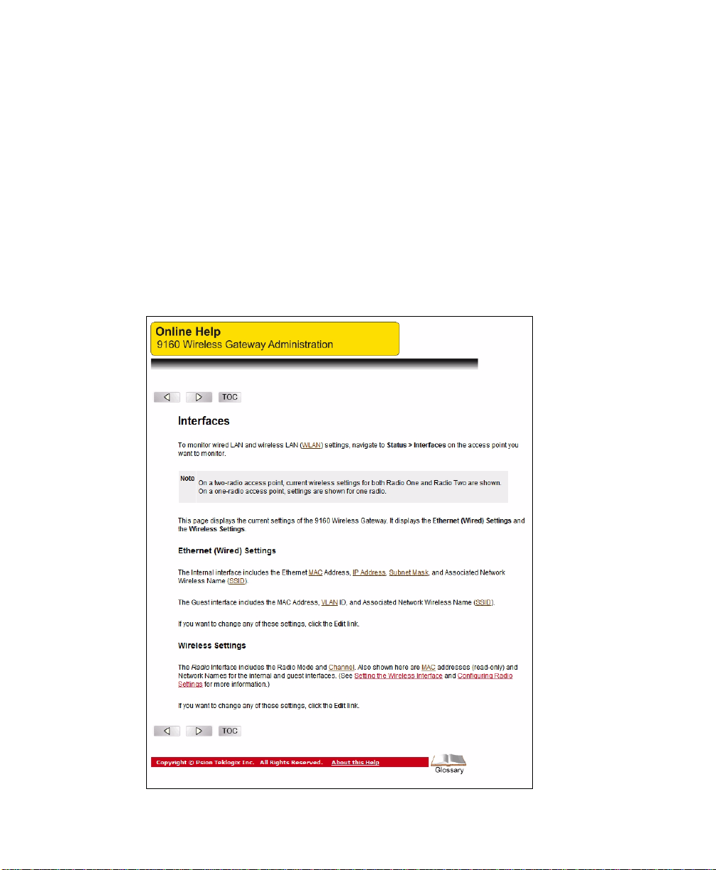
11.1 Interfaces ..................................119
Psion Teklogix 9160 G2 Wireless Gateway User Manual v
Page 10

Contents
11.1.1Ethernet (Wired) Settings........................120
11.1.2Wireless Settings.............................120
11.2 Event Logs .............. ....... ...... ......120
11.2.1Log Relay Host For Kernel Messages..................121
11.2.1.1 Understanding Remote Logging...................121
11.2.1.2Setting Up The Log Relay Host...................122
11.2.1.3 Enabling Or Disabling The Log Relay Host On The Status,
Events Page.............................123
11.2.2Events Log................................124
11.3 Transmit/ Recei ve Statistics .........................124
11.4 Associated Wireless Clients.........................126
11.4.1Link Integrity Monitoring........................126
11.5 Neighboring Access Points .........................126
Chapter 12: The Ethernet (Wired) Interface
12.1 Navigating To Ethernet (Wired) Settings..................133
12.1.1Setting The DNS Name.........................134
12.1.2 Enabling Or Disabling Guest Access ..................134
12.1.2.1Configuring An Internal LAN And A Guest Network.......134
12.1.2.2Enabling Or Disabling Guest Access................135
12.1.2.3Specifying A Virtual Guest Network................135
12.1.3Enabling / Disabling Virtual Wireless Networks On The AP......136
12.1.4 Configuring LAN Or Internal Interface Ethernet Settings. . ......136
12.1.5Configuring Guest Interface Ethernet (Wired) Settings.........138
12.1.6Updating Settings............................138
Chapter 13: Setting the Wireless Interface
13.1 Navigating To Wireless Settings......................141
13.2 Configuring 802.11d Regulatory Domain Support . ............142
13.3 802.11h Regulatory Domain Control....................142
13.4 Configuring The Radio Interface......................143
13.5 Configuring “Internal” Wireless LAN Settings...............145
13.6 Configuring “Guest” Network Wireless Settings..............146
13.7 Updating Settings..............................146
vi
Psion Teklogix 9160 G2 Wireless Gateway User Manual
Page 11

Contents
Chapter 14: Setting up Guest Access
14.1 Understanding The Guest Interface....................149
14.2 Configuring The Guest Interface......................150
14.2.1Configuring A Guest Network On A Virtual LAN...........150
14.2.2Configuring The Welcome Screen (Captive Portal) ..........152
14.3 Using The Guest Network As A Client .................. 152
14.4 Deployment Example............................153
Chapter 15: Configuring VLANs
15.1 Navigating To Virtual Wireless Network Settings .............157
15.2 Configuring VLANs................... ...... ...157
15.3 Updating Settings..............................159
Chapter 16: Configuring 802.11 Radio Settings
16.1 Understanding Radio Settings.......................163
16.2 Navigating To Radio Settings .............. .........164
16.3 Configuring Radio Settings...................... ...165
16.4 Updating Settings..............................169
Chapter 17: MAC Address Filtering
17.1 Navigating To MAC Filtering Settings...................173
17.2 Using MAC Filtering............................174
17.3 Updating Settings..............................174
Chapter 18: Load Balancing
18.1 Understanding Load Balancing.......................177
18.1.1 Identifying Imbalance: Overworked Or Under-util ize d Acces s Poi nts. 177
18.1.2 Specifying Limits For Utilization And Client Associati ons . . . . . . 178
18.1.3Load Balancing And QoS........................178
18.2 Navigating To Load Balancing Settings..................178
18.3 Configuring Load Balancing........................179
18.4 Updating Settings..............................180
Psion Teklogix 9160 G2 Wireless Gateway User Manual vii
Page 12

Contents
Chapter 19: Quality of Service (QoS)
19.1 Understanding QoS....................... ......183
19.1.1QoS And Load Balancing........................183
19.1.2 802.11e And WMM St andar ds Su pport .................183
19.1.3QoS Queues And Parameters To Coordinate Traffic Flow.......184
19.1.3.1QoS Queues And Type Of Service (ToS) On Packets........184
19.1.3.2 EDCF Control Of Data Frames And Arbitrati on I nter fr ame Spac es186
19.1.3.3 Random Backoff And Minimum/Maximum Contention Windows. 187
19.1.3.4Packet Bursting For Better Performance ..............188
19.1.3.5 Transmissi on Oppor tunity (TXOP) Interval For Clien t Stations . .188
19.1.4802.1p And DSCP Tags.........................188
19.1.4.1VLAN Priority............................190
19.1.4.2DSCP Priority............................190
19.2 Configuring QoS Queues..........................191
19.2.1Configuring AP EDCA Parameters...................192
19.2.2Enabling/Disabling Wi-Fi Multimedia..................193
19.2.3Configuring Station EDCA Parameters.................194
19.3 Updating Settings..............................195
Chapter 20: Wireless Distribution System
20.1 Understanding The Wireless Distribution System.............199
20.1.1Using WDS To Bridge Distant Wired LANs..............199
20.1.2 Using WDS To Extend Network Beyond The Wired Coverage Area. . 200
20.1.3Using WDS To Create Backup Links ..................201
20.2 Security Considerations Related To WDS Links ..............201
20.2.1Understanding Static WEP Data Encryption..............202
20.2.2Understanding WPA (PSK) Data Encryption........ ......202
20.3 Configuring WDS Settings.........................203
20.3.1Example Of Configuring A WDS Link.................206
20.4 Updating Settings..............................207
Chapter 21: Configuring SNMP
21.1 Understanding SNMP Settings........... ............211
viii
Psion Teklogix 9160 G2 Wireless Gateway User Manual
Page 13

Contents
21.2 Navigating To SNMP Settings.......................213
21.3 Configuring SNMP Settings........................ 214
21.3.1Configuring SNMP Traps........................215
21.3.2Updating SNMP Settings........................216
Chapter 22: The 9160 G2 As Base Station
22.1 Overview..................................219
22.2 Radio Protocols...............................220
22.2.1Adaptive Polling/Contention Protocol.................220
22.3 Narrow Band Menus ............................221
22.3.1Narrow Band Radio Configuration Settings..............221
22.3.1.1 RA1001A Radio Parameters ....................222
22.3.2Connectivity Options..........................223
22.3.3Connectivity Options: Base Station Mode...............223
22.3.3.1Polling Protocol Parameters.....................225
22.3.3.2Radio Parameters..........................227
22.3.4Connectivity Options: RRM Mode...................229
22.4 Connectivity Menus ............................230
22.4.1Base Station Configuration Settings ..................231
22.4.2 RRM Groups Configuration Settings . . . ...............232
22.4.2.1 RRM Groups ............................234
22.4.2.2Polling Protocol Parameters.....................235
22.4.2.3Radio Parameters..........................237
22.4.2.4 Group Parameters ..........................238
22.4.2.5Remote Radio Modules.......................238
22.4.3Radio Link Features Configuration Settings..............239
22.4.3.1Radio Link Features.........................240
22.4.3.2Automatic Radio Address......................241
22.4.3.3Automatic Terminal Number....................242
22.5 Hosts....................................243
Chapter 23: Network Time Protocol Server
23.1 Navigating To Time Protocol Settings...................249
23.2 Enabling Or Disabling A Network Time Protocol (NTP) Server . . . . . 250
Psion Teklogix 9160 G2 Wireless Gateway User Manual ix
Page 14

Contents
23.3 Updating Settings..............................250
Chapter 24: Backing Up & Restoring Configuration
24.1 Navigating To The AP’s Configuration Settings..............253
24.2 Resetting Factory Default Configuration..................253
24.3 Saving The Current Configurati on To A Backup File ...........254
24.4 Restoring The Configuration From A Previously Saved File........254
24.5 Rebooting The Access Point ........................255
24.6 Upgrading The Firmware..........................255
24.6.1Update..................................257
24.6.2Verifying The Firmware Upgrade....................257
Chapter 25: Specifications
25.1 Physical Description ............................261
25.2 Environmental Requirements........................261
25.3 AC Power Requirements..........................261
25.4 Power Over Ethernet Requirements.....................262
25.5 Processor And Memory...........................262
25.6 Network Interfaces .............................262
25.7 Radios....................................262
Appendices
Appendix A: Support Services And Worldwide Offices
A.1 Technical Support..............................A-1
A.2 Product Repairs ...............................A-1
A.3 Worldwide Offices..............................A-2
Appendix B: Port Pinouts And Cable Diagrams
B.1 Console Port.................................B-1
B.2 Serial Cable Descriptions..........................B-2
B.3 RJ-45 Connector Pinouts (10 BaseT/ 100BaseT Ethernet)..........B-3
x
Psion Teklogix 9160 G2 Wireless Gateway User Manual
Page 15

Contents
Appendix C: Security Settings On Wireless Clients And RADIUS Server
Setup
C.1 Network Infrastructur e And Choosing Between Bui lt-in Or Exte rnal Authenti -
cation Server................................C-4
C.1.1 Using The Built-in Authentication Server (EAP-PEAP)........C-4
C.1.2 Using An External RADIUS Server With
EAP-TLS Certificates Or EAP-PEAP.................C-4
C.2 Make Sure The Wireless Client Software Is Up-to-Date..........C-5
C.3 Accessing The Microsof t Windows Wireless Client Secur it y Sett in gs . . C-5
C.4 Configuring A Client To Access An Unsecure Network
(No Security)................................C-7
C.5 Configuring Static WEP Security On A Client...............C-8
C.6 Configuring IEEE 802.1x Sec uri ty On A Cli ent .............C-11
C.6.1 IEEE 802.1x Client Using EAP/PEAP . . .............. C-11
C.6.2 IEEE 802.1x Client Usin g EAP/TLS Cert if icate . . . ........C-15
C.7 Configuring WPA/WPA2 Enterprise (RADIUS) Security On A Client . C-19
C.7.1 WPA/WPA2 Enterprise (RADIUS) Client Using EAP/PEAP . . . . C-20
C.7.2 WPA/WPA2 Enterprise (RADIUS) Client Using
EAP-TLS Certificate.........................C-24
C.8 Configuring WPA/WPA2 Personal (PSK) Security
On A Client................................C-28
C.9 Configuring An External RADIUS Ser ver To Recognize The 9160 G2 Wire-
less Gateway............................. ..C-30
C.10Obtaining A TLS-EAP Certificate For A Client.............C-34
C.11Configuring RADIUS Server For VLAN tags..............C-38
C.11.1 Configuring A RADIUS Server ...................C-39
Appendix D: Troubleshooting
D.1 Wireless Distribution System (WDS) Probl ems And Sol utions . . . . . . D-3
D.2 Cluster Recovery..............................D-4
Psion Teklogix 9160 G2 Wireless Gateway User Manual xi
Page 16

D.2.1 Reboot Or Reset Access Point . ....................D-4
Appendix E: Glossary
Index............................................1
Page 17

APPROVALS AND SAFETY SUMMARY
DECLARATION OF CONFORMITY
Product: 9160 G2 Wireless Gateway
Application of
Council Directives: EMC Directive:89/336/EEC
Low Voltage Directive:73/23/EEC
R&TTE Directive: 1999/5/EEC
Conformity Declared
to Standards: EN 55022: 2003 Class B
EN 61000-3-2; EN 61000-3-3
EN 55024:2003
ETSI EN 300 328:2003
ETSI EN 301 489-17:2002
EN 60950-1: 2001
Manufacturer: PSION TEKLOGIX INC.
2100 Meadowvale Blvd.
Mississauga, Ontario; Canada L5N 7J9
Year of Manufacture: 2005
Manufacturer’s Address in the
European Community: PSION TEKLOGIX S.A.
La Duranne
135 Rue Rene Descartes; BP 421000
13591 Aix-En-Provence
Cedex 3; France
Type of Equipment: Information Technology Equipment
Equipment Class: Commercial and Light Industrial
Psion Teklogix 9160 G2 Wireless Gateway User Manual xiii
Page 18

Approvals And Safety Summary
FCC Statement
FCC DECLARATION OF CONFORMITY (DOC)
Applicant’s Name & Address: PSION TEKLOGIX
2100 Meadowvale Blvd.
Mississauga, Ontario, Canada L5N 7J9
Telephone No.: (905) 813-9900
US Representative’s Name & Address: Psion Teklogix Corp.
1810 Airport Exchange Blvd., Suite 500
Erlanger, Kentucky, 41018, USA
Telephone No.: (859) 372-4329
Equipment Type/ Environment Use: Computing Devices
Trade Name / Model No.: 9160 G2 Wireless Gateway
Year of Manufacture: 2005
Standard(s) to which Conformity is Declared:
The 9160 G2 Wireless Gateway, supplied by Psion Teklogix, has been tested and found
to comply wi th FCC PART 15, SUBPART B - UNINTENTIONAL RADIATORS,
CLASS B COMPUTING DEVICES FOR HOME & OFFICE USE.
Applicant: Psion Teklogix Inc.
Legal Representative in US: Psion Teklogix Corp.
The 9160 G2 Wireles s Ga teway has been t est ed and fo und to compl y wi th t he spec ifications for a Class B digital device, pursuant to Part 15 of the FCC Rules. Operation is subject to the fol lowi ng t wo condi ti ons:
1. This device may not cause harmful inte rf erence, and
2. This device must accept any int erf ere nce r ece ived, including interference that may cause undesired ope ration.
These limits are designed to provide reasonable protection against harmful interfer-
xiv
Psion Teklogix 9160 G2 Wireless Gateway User Manual
Mississauga, Ontario, Canada
Erlanger, Kentucky, USA
Page 19

Approvals And Safety Summary
ence in a residential installation. This equipment generates, uses, and can radiate
radio frequency energy and, if not installed and used according to the instructions,
may cause harmful interference to radio communications. However, there is no
guarantee that interference will not occur in a particular installation. If this equipment does cause harmful interference to radio or television reception, which is
found by turning the equipment off and on, the user is encouraged to try to correct
the interference by one or mor e of the f oll owing measures:
• Reorient or relocate t he r eceiving antenna.
• Increase the separation between the equipment or devices.
• Connect the equipment t o an out le t other than the receiver's.
• Consult a dealer or an experi enced radio/TV technician for assistance.
FCC Caution: Any change or modification to the product not expressly
approved by Psion Teklogix could void the user's authority to
operate the device.
RF Radiation Exposure Statement
To comply with the FCC and ANSI C95.1 RF exposure limits, the ante nna(s) for
this device must comply wi th the f oll owing:
• All Access Point antennas must operate with a separation distance of at least
25 cm (9.8 in.) from all persons using the cable provided, and must not be
co-located or operating in conjunction with any other antenna or transmitter.
• The Gabriel dish antenna (P/N 9002006) requires a minimum separation
distance of 63.2 cm (24.9 in.).
Note: Dual antennas used f or diversity operation are not considered co-located.
Industry Canada (IC) Department Of Communications Notice
This Class B digital apparatus complies with Canadian ICES-003 and RSS-21 0.
“To prevent radio interference to the licensed service, this device is intended to be
operated indoors and away from windows to provide maximum shielding. Equipment (or its transmit anten na) t h at is inst al led outdoors is subject to licensing.”
Cet appareil numérique de la classe B est confor me à la norme NMB-003 et CNR210 du Canada. “Pour empêcher que cet appareil cause du brouillage au service faisant l'objet d'une licence, il doit être utilisé à l'intérieur et devrait être placé loin des
fenêtres afin de fourn ir un écran de bl indage maxima l. Si le matéri el (ou son ante nne
d'émission) est insta ll é à l 'extérieur, il doit faire l'objet d'une licence.”
Psion Teklogix 9160 G2 Wireless Gateway User Manual xv
Page 20

Approvals And Safety Summary
SAFETY APPROVALS
CSA, NRTL/ C and CB.
CE MARKING
When used in a residential, commercial or light industrial environment, the product and
its approved UK and European peripherals fulfill all requirements for CE marking.
R&TTE DIRECTIVE 1999/5/EC
This equipment complies with the e sse ntial requirements of EU Directi ve
1999/5/EC (Declaration avail abl e: www.psionteklogix.com).
Cet équipement est conforme aux pr inci pal es c ara ctéristiques définies dans la
Directive européenne RTTE 1999/5/CE. (Déclaration disponible sur le site:
www.psionteklogix.com).
Die Geräte erfüllen die grundlegenden Anforderungen der R TTE- Rich tli ni e
(1999/5/EG). (Den Wortlaut der Richtlinie finden Sie unte r:
www.psionteklogix.com).
Questa apparecchiatura è con for me ai requisiti essenziali della Direttiva Europea
R&TTE 1999/5/CE. (Dichiarazione disponi bil e su l si to: www.psionteklogix.com).
Este equipo cumple los requisi tos principales de la Directiva 1995/5/CE de la UE,
“Equipos de Terminales de Radio y Telecomunicaciones”. (Declaración disponible
en: www.psionteklogix.com).
Este equipamento cumpre os requisitos essenciais da Directiva 1999/5/CE do Parlamento Europeu e do Conselho (Directi va RTT). (Declaração disponível no
endereço: www.psionteklogix.com).
Ο εξοπλισμός αυτός πληροί τις βασικές απαιτήσεις της κοινοτικής οδηγίας EU
R&TTE 1999/5/EΚ. (Η δήλωση συμμόρφωσης διατίθεται στη διεύθυνση:
www.psionteklogix.com)
Deze apparatuur voldoet aan de n oodzakelijke vereisten van EU-richtlijn betreffende radioapparatuur en t ele communica tie-eindapparatuur 199/5/EG. (verklaring
beschikbaar: www.psionteklogix.com).
Dette udstyr opfylder de Væsent li ge kr av i EU' s di rekt iv 1999/5/EC om Radio- og
teleterminaludstyr. (Erklæring findes på: www.psionteklogix.com).
xvi
Psion Teklogix 9160 G2 Wireless Gateway User Manual
Page 21

Approvals And Safety Summary
Dette utstyret er i overe nsst emmelse med hovedkravene i R&TTE-direkt ive t
(1999/5/EC) fra EU. (Erklæri ng fi nnes på: www.psionteklogix.com).
Utrustningen uppfyller kra ven f ör EU-direktivet 1999/5/EC om ansluten teleutrustning och ömsesidigt erkännande a v utr ust ningens överensstämmelse (R&TTE).
(Förklaringen finns att l äsa på: www.psionteklogix.com).
Tämä laite vastaa EU:n radio- j a t ele päät ela it edi rekt ii vin (EU R&TTE Directive
1999/5/EC) vaatimuksia. (Julkilausuma nähtävillä oso it tee ssa:
www.psionteklogix.com).
Psion T eklogix tímto prohlašuje, že 9160 G2 Wireless Gateway je ve shodě se základními
požadavky a dalšími příslušnými ustanoveními směrnice 1995/5/ES (NV č. 426/2000 Sb.)
a Prohlášení o shodě je k dispozici na www .psionteklogix.com.
T oto zaríze ní lze provozov at v Čes ké republic e na základě generální licence č. GL-12/R/2000.
Psion T eklogix týmto vyhlasuje, že 9160 G2 Wireless Gateway spĺňa základné požiadavky
a všetky príslušné ustanovenia Smernice 1995/5/ES (NV č. 443/2001 Z.z.) a V yhlásenie o
zhode je k dispozícii na www.psionteklogix.com.
T oto zariadenie j e možné prevádzkovat’ v Slovenskej r epublike na základe Všeobecného
povolenia č. VPR-01/2001.
IMPORTANT SAFETY INSTRUCTIONS
This safety informati on is f or the p rot ection of both op eratin g and servic e person nel.
• The 9160 G2 must be installed by a quali fied Psio n Teklogix installer—failure to have the 9160 G2 properly i nst all ed wil l vo id t he Manuf act urer’s
warranty.
• The mains power cord (if sold separatel y) shall comply with Nationa l safety
regulations of the country where the equipment i s to be used.
• Use of an attachment not recommende d or sold by manufa cturer may resul t
in fire, electric shock, o r per sona l i njur y.
• T o redu ce risk of damage to the elect ric plug and co rd when unplugg ing the
9160 G2, pull the plug rather tha n the cord.
• Make sure the cord is positi oned so tha t it is not st epped on, trip ped over , or
otherwise subjected to damage or stress.
• Do not operate t he 91 60 G2 wi th a damage d cor d or plug . Repla ce i mmedi ately.
Psion Teklogix 9160 G2 Wireless Gateway User Manual xvii
Page 22

Approvals And Safety Summary
• Do not operate the 9160 G2 if it has received a sharp blow , been dropped, or
otherwise damaged in any way; it should be inspected by qualified service personnel.
• Do not disassemble the 9160 G2; it s houl d be r epai red by qualified service
personnel. Incorrect reassembly may result in electric shock or fire .
• To reduce risk of electric shock, unplug the 9160 G2 fr om the outlet before
attempting any maintenance or c lea ning.
• An extension cord should not be us ed unl ess absol utely necessary. Use of
an improper extension cord co uld result i n fire or ele ctric shock. If an exte nsion cord must be used, make sure:
• The plug pins on the extension cord are the same number, size, and
shape as those on the adaptor.
• The extensi on cor d i s pro perl y wir ed, i n good electrical condition, a nd
that the wire size is larger than 16 AWG.
• The 9160 G2 is designed for indoor use only; do not expose the 9160 G2 to rain or
snow .
DO NOT OPERATE IN AN EXPLOSIVE ATMOSPHERE
Operating Psion Teklogix equipment where explosive gas is present may
result in an explosion.
DO NOT REMOVE COVERS OR OPEN ENCLOSURES
To avoid injury, the equipment covers and enclosures should only be
removed by qualified service personnel. Do not operate the equipment
without the covers and enclosu res prope rly installed.
DO NOT HOLD ANTENNA
To avoid discomfort due to the local heating effect of radio frequency
energy, do not touch the antenna when a 9160 G2 is transmitting .
CONNECTION TO OUTDOOR ANTENNA
The outdoor antenna shall only b e installed by Psion Teklogix
service professional s.
xviii
Psion Teklogix 9160 G2 Wireless Gateway User Manual
Page 23

INTRODUCTION 1
1.1 About This Manual..............................3
1.2 Online Help Features, Supported Browser s, And Li mitat io ns ........6
1.3 Text Conventions . . .............................7
1.4 Overview Of The 9160 G2 W i rel ess Gatewa y ................7
1.4.1 Radios.................................8
1.4.2 Access Point Functions........................9
1.4.3 Base Station Functions........................9
1.5 Features and Benefits.............................10
1.5.1 IEEE Standards Support And Wi-Fi Compliance. . . . . . . . . . 10
1.5.2 Wireless Features..........................10
1.5.3 Security Features..........................11
1.5.4 Out-of-the-Box Guest Interface...................12
1.5.5 Clustering And Auto-Management.................12
1.5.6 Networking.............................13
1.5.7 SNMP Support . . . . . . . . . . . . . . . . . . . . . . . . . . . 13
1.5.8 Maintainability...........................14
1.6 What’s Next?..................................14
Psion Teklogix 9160 G2 Wireless Gateway User Manual 1
Page 24

Page 25

Chapter 1: Introduction
About This Manual
1.1 About This Manual
This manual describes the set up, conf iguration, administration, and maintenance of
one or more 9160 G2 W ir ele ss Gat eways on a wireless network.
Chapter 1: Introduction
provides an overview of this manu al and 9160 G2 Wireless Gateway features.
Chapter 2: Installation Requirements
explains the physical install ation of t he 9160 G2 W i reles s Gateway, and how to
connect to the 9160 G2 for di agnos tics.
Chapter 3: PreLaunch Checklist
provides a quick check of requi re d har dware components, software, client configurations, and compatibility issues.
Chapter 4: Quick Steps For Setup And Launch
is a step-by-step guide to set ti ng up you r 9160 G2 Wirele ss Gat eways and the
resulting wireless networ k.
Chapter 5: Configuring Basic Settings
provides instructions on c onfiguring administrator access settings and new
access point setting s.
Chapter 6: Managing Access Points & Clusters
describes access point cl uste rs and how to navigate to specific access points
within clusters.
Chapter 7: Managing User Accounts
illustrates the user mana gement capabilities for controlling client access to
access points.
Chapter 8: Channel Management
describes how the 9160 G2 Wireless Gateway automatically assigns r adio cha nnels used by clustered access points to reduce mutual interference or interference with other access po int s out sid e of i ts cluster.
Chapter 9: Wireless Neighborhood
provides a detailed view of ne ighborhood access points, including identifying
information, cluster status, and statistical information.
Psion Teklogix 9160 G2 Wireless Gateway User Manual 3
Page 26

Chapter 1: Introduction
About This Manual
Chapter 10: Configuring Security
provides a number of authenticatio n and encryption schemes to ensure that your
wireless infrastructur e i s accessed only by the intended users. The details of
each security mode are descri bed.
Chapter 11: Maintenance And Monitoring
describes the maintenan ce and monitoring tasks fo r i ndi vidua l access points
(not for cluster conf igur at ions ).
Chapter 12: The Ethernet (Wired) Inte rface
describes how to configure the wired interface settings on the 9160 G2
Wireless Gateway.
Chapter 13: Setting the Wireless Interface
describes how to configur e th e wireless address and related settings on the
9160 G2 Wirel ess Ga teway.
Chapter 14: Setting up Guest Access
allows you to configure the 9160 G2 Wir ele ss Gat eway f or c ontr o ll ed gu est
access to an isolated networ k.
Chapter 15: Configuring VLANs
describes how to configure multiple wireless networks on Virtual LANs (VLANs).
Chapter 16: Configuring 802.11 Radio Settings
describes how to configure Radi o Set ti ngs on t he 9160 G2 Wireless Gateway
Chapter 17: MAC Address Filtering
instructs how you can use MAC address filter ing to control client access to your
wireless network.
Chapter 18: Load Balancing
describes how to configure Load Ba lan cing on your wire less network, to allow
you to balance the distr ibu tio n of wi rel ess client connections across multiple
access points.
Chapter 19: Quality of Service (QoS)
provides instructions on c onfi guri ng t he par amet ers on multiple queues to
improve the throughput and pe rf ormance of differentiated wireless traff ic.
Chapter 20: Wireless Distribution System
describes how to configure the Wireless Distribution System (WDS) on the
9160 G2 Wirel ess Ga teway, enabling you to connect multip le a cces s points
which can then communicate with one another wireles sly in a standardized way .
Psion Teklogix 9160 G2 Wireless Gateway User Manual
4
Page 27

Chapter 1: Introduction
About This Manual
Chapter 21: Configuring SNMP
describes how to configure SNMP and rel ated setti ngs on the 9160 G2 W irele ss
Gateway Enterprise-Manager API.
Chapter 22: The 9160 G2 As Base Stat ion
describes how to configure th e 9160 G2 Wireless Gateway as either a wired or
wireless Base Stati on, or a s a Remot e Radi o Mo dule (RRM). This chapt er als o
describes narrow band radio configuration settings.
Chapter 23: Network Time Protocol Server
describes how to configure th e 9160 G2 Wireless Gateway to use a specified
Network Time Prot oco l (NTP) ser ver to synchronize computer clock times on
your network.
Chapter 24: Backing Up & Restoring Configuration
shows how to backup a configuratio n fi le that can be used at a later date to
restore the access point t o t he previously saved configuration.
Chapter 25: Specifications
details the physic al, environmental, and various operating specifications for the
9160 G2 Wirel ess Ga teway a nd i ts r adi os.
Appendix A: Support Services And Worldwide Offices
presents information for t echnical support, contacts, and the Psion Teklogix
worldwide web address.
Appendix B: Port Pinouts And Cable Diagrams
includes pinouts and diagrams o f t he por ts and cables for the 9160 G2.
Appendix C: Security Settings On Wireless Clients And RADIUS Server Setup
details how to configure sec uri ty s ett ings on t h e cl ien t t o match the security
mode being used by each network (AP) connection.
Appendix D: Troubleshooting
describes how to solve common pr oblems pos sibly en countere d while upd ating
network configurations on net works served b y multiple, clust ered access point s.
Appendix E: Glossary
provides definitions and further details on terms featured in bold it alics throug hout the manual.
Psion Teklogix 9160 G2 Wireless Gateway User Manual 5
Page 28
Chapter 1: Introduction
Online Help Features, Supported Browsers, And Limitations
1.2 Online Help Features, Supported Browsers, And Limitations
Online Help for the 9160 G2 Wireless Gateway provides information about all
fields and features avai labl e on the user interface. The information in the Online
Help is a subset of the infor mati on available in the full User Manual.
Online Help informatio n corre sponds t o each t ab on t he 9160 G2 Wireless Gateway
Administration user inter face . Cli ck th e Help button on a tab or the “More. . .” link
at the bottom of the online he lp panel on the UI for help i nform ation fo r the set tings
on the current tab.
Psion Teklogix 9160 G2 Wireless Gateway User Manual
6
Page 29

Chapter 1: Introduction
s
Text Conventions
1.3 Text Conventions
Note: Notes highlight additional helpful information.
Important: These statements provide particularly important instructions or
additional information that is critical to the operatio n of the
computer and other equipment.
Warning: These statements pro vide important information that may prevent
injury, damage to t he equi pment , or l oss of data.
An arrow next to field desc ri pti on information (usually in tables) indicates a r ecommended or suggested configurat ion s ett ing for an option on the Access Point (AP).
Bold Italic
When you see a term writte n in bold italics, there is an entry for it in Appendix E:
Glossary, providing a definition and further details. Not a ll ter m s ar e hi ghl ight ed i n
the manual, but the Glossary is e xtensive, therefore please check there for any unfamiliar words or expressions.
1.4 Overview Of The 9160 G2 Wireless Gateway
The 9160 G2 Wirel es s Gate way provides continuous, high-speed access between
your wireless and Ethernet de vice s. It is an advanced, standards-based solution for
wireless networking in small and medi um-si zed businesses. The 9160 G2 Wireless
Gateway enables zero-administ ration wireless local area network (WLAN) deployment while providing state-o f-t he- art wir eless networking features.
The 9160 G2 Wi reless Gateway pr ovides best-of -breed securi ty, ease-of-administration and industry standards —pr ovidi ng a standalone and fully-secured wireless
network without the need for additional management and security server soft ware.
The 9160 G2 Wire less Gateway is des igned to sup port a wide varie ty of system co nfigurations. Using the IEEE 802.11 Wireless LAN Standar ds, t he 9160 G2 is
capable of operating as a tr ans parent bridge (access point) between wireless and
wired networks. This allows wirel ess cl ient s t o acc ess t he network and also move
seamlessly between the 9 160 G2s in t he network. The 9160 G2 can also operate a s a
base station, a remote radio modu le ( RRM), and bec ome par t of a mapRF system.
The following sections list features and benefits of the 9160 G2 Wirele ss Gat eway,
and tell you what’s next for when you’re ready to get started using the AP .
Psion Teklogix 9160 G2 Wireless Gateway User Manual 7
Page 30

Chapter 1: Introduction
Radios
1.4.1 Radios
The 9160 G2 is capable of supporting single or dua l radio operation. Available radio
modules are the 802.1 1a/g radi o, the 802.1 1g radio, and the RA1001A Narrow Band
radio. For detailed specif ica ti ons on t hes e ra dios please see “Radios” on page 262.
Depending on the installed ra dio( s) , the access point is capable of operating in the
following modes:
• IEEE 802.11b mode.
• IEEE 802.11g mode.
• IEEE 802.11a mode.
• Atheros Tur bo 5 GHz.
• Atheros Dynamic T urbo 5 GHz .
• Atheros Tur bo 2.4 GHz.
• Atheros Dynamic T urbo 2.4 GHz.
• Extended Range.
• Psion Teklogix Narrow Band Polling Protocol.
Important: Psion Teklogix terminals do not support Atheros Turbo modes
and to prevent unneces sary rad io overhea d the use of Turbo mode
is not recommended.
The 9160 G2 Wirel es s Gate wa y supp ort s fo ur di fferent radio configurations:
802.11g, 802.11g + 802.11ag, NB (narrow band), and NB + 802.11ag.
These different var ia nts a re iden tif ied by the “Model” value, which is shown on the
Maintenance > Upgrade web page ( see Figure 1.1 on page 9). The models are
defined as follows:
• 9160 W i reless Gateway = 802.11g.
• 9160 W i reless Gateway (Dual Radio) = 802.11g + 8 02.11ag.
• 9160 W i reless Gateway NB = NB.
• 9160 W i reless Gateway NB (Dual Radio) = NB + 802.11ag.
Psion Teklogix 9160 G2 Wireless Gateway User Manual
8
Page 31

Chapter 1: Introduction
Access Point Functions
Note: For the ‘NB only’ case, the web page may show the configuration page
for a single 802.11 radio. You can disregard it, however, if you should
attempt to configure this non-existent radio, this will not cause problems
in the 9160 G2.
Figure 1.1 Upgrade Firmware Web Page
1.4.2 Access Point Functions
As an access point connected to a wired network, the 9160 G2 Wireless Gateway
forms a communication link bet ween Psion Teklogix RF terminal s or wireless
access point clients and a Psion Teklogix Network Controll er or a host compute r. It
communicates over an IEEE 802.11 RF data link with terminals, and over a cable
with the network controller or a host computer. The 9160 G2 can be connected to
the network through an Ethernet connection.
1.4.3 Base Station Functions
As a base station or Remote Radio Module (RRM) , the 9160 G2 pr ovi des a link
between the local area ne twor k and wi rel ess mob il e te rm ina ls us ing proprietary
Psion Teklogix radio protocols. On the local area network the 9160 G2 bas e stati on
(or RRM) communicates with a 9500 net w ork cont rol le r ( or host using a Psion Teklogix Software Development Ki t) u sing the proprietary 9010 protocol over TCP/IP.
For information on configuri ng the 9160 G2 a s a base station or RRM, see Chapter
22: “The 9160 G2 As Base Station”.
Psion Teklogix 9160 G2 Wireless Gateway User Manual 9
Page 32

Chapter 1: Introduction
Features and Benefits
1.5 Features and Benefits
1.5.1 IEEE Standards Support And Wi-Fi Compliance
• Support for IEEE 802.11a, IEEE 802.11b, IEEE 802.11g, IEEE 802.11i,
and IEEE 802.3af wireless networking standards.
• Provides bandwidth of up to 54 Mbps for IEEE 802.11a or IEEE 802.11g
(11 Mbps for IEEE 802.11b, 108 Mbps for Atheros 802.11a Turbo).
• Wi-Fi cer ti fication.
1.5.2 Wireless Features
• Auto channel selection a t st art up.
• Transmit powe r adj ust ment.
• Wireles s Dis tr ibut ion Syst em (WDS) fo r connec ti ng multiple access points
wirelessly. Extends your network with less cabling.
• Quality of Service (QoS) for enhanced throughput and better performance
of time-sensitive wirele ss t raffic like Video, Audio, Voice over IP (VoIP)
and streaming media. Our QoS is Wi-Fi Multimedia (WMM) compliant.
• Load Balancing.
• Built-in support f or multipl e SSIDs (network names) and multiple BSSIDs
(basic service set I Ds) on the same access point.
Two special-purpose BSSIDs are supported, one for the Inter n al ( pri mary
and management) network, and the o ther for th e gues t ne twork. Six additional general-purpo se BSSIDs (called Virtual Wireless Networks or
VWNs) are supported using VLANs.
• Channel management for automati c coordination of radio channel
assignments to reduc e AP-to-AP i nterferen ce on the network an d maximize
Wi-Fi bandwi dth.
• Neighboring access point detection (also known as “rogue” AP detection).
• Support for IEEE 802.11d Regulatory Domain select ion (country codes for
global operation).
Psion Teklogix 9160 G2 Wireless Gateway User Manual
10
Page 33

• Support for IEEE 802.11h, incorp orat ing TPC and DFS.
IEEE 802.11h is a st anda rd t hat p rovi des t w o se rvi ces r equi re d to satisfy
certain regulatory d omains for the 5 GHz band. These two services are
Transmit Power Control (TPC) and Dynamic Frequency Selection (DFS).
• Support for Extended Range (XR).
• SpectraLink Voice Prio rit y ( S VP).
SpectraLink Voice Prio rit y ( SVP) is a QoS appr oach for Wi-Fi deployments. SVP is an open specificati on th at i s compliant with the IEEE
802.11b sta ndard . SVP mi nimiz es de lay and prioritizes voice packets over
data packets on the Wireless LAN, thus increasing the probability of b ett er
network performance.
1.5.3 Security Features
• Inhibit SSID Broadcast.
• Ignore SSID Broadcast.
• Weak IV avoidance.
Chapter 1: Introduction
Security Features
• Wireles s Equi vale nt Pr iva cy (WEP).
• Wi-Fi Cert if ied for the following standards:
- IEEE Standards: 802.11b, 802.11g, 802.11d
- Security:
WPA™ - Personal
WPA™ - Enterprise
WPA2™ - Personal
WPA2™ - Enterprise
- EAP Types:
EAP-TLS
EAP-TTLS/MSCHAPv2
PEAPv0/EAP-MSCHAPv2
PEAPv1/EAP-GTC
EAP-SIM
• Advanced Encryption St anda rd (AES).
• User-based acces s control with local authentication server.
Psion Teklogix 9160 G2 Wireless Gateway User Manual 11
Page 34

Chapter 1: Introduction
Out-of-the-Box Guest Interface
• Local user database and user life cycle management.
• MAC address filtering.
• WPA/WPA2 over WDS.
• Secure Sockets Shell (SSH).
• Secure Sockets Layer (SSL).
1.5.4 Out-of-the-Box Guest Interface
• Unique network name (SSID) for the Guest interface.
• Captive portal to guide guest s t o customizable, guest-only Web page.
• VLAN and ethernet options.
1.5.5 Clustering And Auto-Management
• Provisioning and auto-co nfi gura ti on of APs thr ough cl ust er ing a nd cl uster
rendezvous.
The administrator can spec ify how new access points should be configured
before they are added to the network. When new access points are a dded,
they can automatically rende zvous with the c lus ter, and securely download
the correct configuration. The pr ocess does not require manual in tervention,
but is under the control of t he administrator.
• Single universal view of clu stered access points and cluster configuration
settings.
Configuration for all acce ss po int s in a cl uster can be managed from a
single interface. Changes to common param eters are automat ically refle cted
in all members of the cluster.
• Self-managed access points with automatic configuration synchronization.
The access points in a cl ust er periodically check that the cluster configuration is consistent, and chec k for the presence and availability of the other
members of the cluster. The administrator can monit or t his information
through the user interfac e.
Psion Teklogix 9160 G2 Wireless Gateway User Manual
12
Page 35

Chapter 1: Introduction
• Enhanced local authenti cat ion us ing 802.1x without additional IT setup.
A cluster can maintain a user authentication server and database stored on
the access points. This eli minat es the need to install, configure, and maintain a RADIUS infrastructure, and simplifi es t he administrative task of
deploying a secure wireless networ k.
1.5.6 Networking
• Dynamic Host Configuration Protoco l (DHCP) suppor t f or dynamically
obtaining network config urat ion inf o rmat ion.
• V irt ual Local Area Network (VLAN) support.
• V irt ual Wireless Networks (Dynamic VLANs).
• Spanning Tre e Prot ocol (STP).
• 802.1p.
1.5.7 SNMP Support
Networking
The 9160 G2 Wirel es s Gate wa y inc lud es t he fo llowing standard Simple Network
Management Protocol (SNMP) Management Informati on Base s ( MIBs):
• Bridge MIB 802.1d (RFC 1493).
• SNMPv2 MIB (RFC 3418).
• IEEE Std 802.11 MIB (base).
• Interfaces Group MIB (RFC 2233).
• Two proprietary MIBs (Wireless MIB and System MIB), based on the
upcoming IEEE 802.1 1k MIB. They p rovi de i nfor mati on about the 9160
G2 Wireles s Gate way cl ient association list and AP detection table,
respectively. The proprietary System MIB provides maintenance
functionality such as syst em re boot o r fi rmwar e upgr ade.
Psion Teklogix 9160 G2 Wireless Gateway User Manual 13
Page 36

Chapter 1: Introduction
Maintainability
1.5.8 Maintainability
• Status, monito rin g, and tracking views of the ne twork incl udi ng session
monitoring, client associa tio ns, t rans mit/ rec eiv e st atistics, and event log.
• Link integrity monitoring t o cont inually verify connection to the client,
regardless of network traffic activity levels.
• Reset configuration option.
• Firmware upgrade.
• Backup and restore of acce ss poi nt conf igur ati on.
• Backup and restore of u ser database f or built-in RADIUS s erver (app licable
with IEEE 802.1x and WPA/WPA2 Enterprise (RADIUS) security modes.
1.6 What’s Next?
Ready to get started with wire les s net w orki ng? Onc e your 9160 G2 Wireless
Gateway is installed (see Chapter 2: “Installation Requirements”), read through
Chapter 3: “PreLaunch Checklist” and then follow the steps in Chapter 4: “Quick
Steps For Setup And Launch”.
Psion Teklogix 9160 G2 Wireless Gateway User Manual
14
Page 37

INSTALLATION REQUIREMENTS 2
2.1 Choosing The Right Location.........................17
2.1.1 Environment.............................17
2.1.1.1 9160 G2 Wireless Gateway.................17
2.1.2 Maintenance.............................18
2.1.3 Radios................................18
2.1.4 Power And Antenna Cables.....................18
2.1.4.1 Power............................18
2.1.4.2 Antennas..........................19
2.2 Connecting To External Devices .......................21
2.2.1 Ports.................................21
2.2.2 LAN Installation: Overview.....................21
2.2.3 LAN Installation: Ethernet.....................22
2.2.3.1 Ethernet Cabling......................22
2.2.4 Status Indicators (LEDs)......................22
2.1.5 Connecting A Video Display Terminal . . . . . . . . . . . . . . . 23
2.2 Changing The Configuration With A Web Browser .............23
Psion Teklogix 9160 G2 Wireless Gateway User Manual 15
Page 38

Page 39

Chapter 2: Installation Requirements
Choosing The Right Location
Warning: The 9160 G2 must be installed by qualified Psion Teklogix personnel.
2.1 Choosing The Right Location
Typically, Psion Teklogix conducts a site survey in th e pla nt and then recommends
the preferred locations for the 9160 G2s. These locations provide good radio coverage, minimize the distance t o t he host computer or network controller , and meet the
environmental requirements.
2.1.1 Environment
2.1.1.1 9160 G2 Wireless Gateway
The 9160 G2 should be located in a well -ve n ti la ted a rea and s hould be protected
from extreme temperature fluctuat io ns (i.e. direct heater output, shipping doors or
direct sunlight). If a pr ote cti ve cover is required, it must have enough ventilation
to maintain the 9160 G2’s surface at or near room temperature.
Refer to Chapter 25: “Specifications” for a more detailed description of environmental requirements. Keep i n mind t hat the long term stability of this equipment
will be enhanced if the envir onment al conditions are less severe than those listed in
this manual.
The 9160 G2 should be situate d away from th e path of vehicle s and fre e from wate r
or dust spray. The 9160 G2 should only be mounted in the upright po sit ion, as
shown in Figure 2.1 on page 18. This ori entation minimizes the risk of water ent ering the 9160 G2, should the unit acc identally be sprayed.
The 9160 G2 is attached to a verti cal sur fa ce us ing f our f asteners on the rear plate
(type of fasteners ar e depende nt on mount ing surf ace). Th e top t wo hol es in t he rear
plate are slots, allowing the unit to be hung in posi tion before the remaining bolts are
installed, thus easing in sta llation. The bolts used for installation are SAE 1/4-20.
Psion Teklogix 9160 G2 Wireless Gateway User Manual 17
Page 40

Chapter 2: Installation Requirements
Maintenance
Figure 2.1 9160 G2 Installation Position
2.1.2 Maintenance
The 9160 G2 has no internal option s witc hes and does not require physical access;
all configuration se tt ings are done remotely (see “Navigating To Basic Settings” on
page 47). Environmental and radio communication considerations do st il l a pply.
Mounting Slot
Cable Tie Mount
Mounting Hole
2.1.3 Radios
• 802.11g radio wit hout integrated antenna (standard).
• 802.11a/g r adi o with out i nte grated antenna (optional second radio).
• RA1001A - Narrow Band (NB) Radio.
2.1.4 Power And Antenna Cables
2.1.4.1 Power
To prevent accidental disconnection and stress on th e 9160 G2, a nte nna and power
cables should be secured within 30 cm of the unit. Secure the cables with ties to
the cable tie mounts on th e 9160 G2 ( see Figur e 2.1) . A single phase power outlet
(range 100 to 240 VAC rated 1.0A minimum) should be installed within one metre
(3.1 feet) of the 9160 G2. The 9160 G2 aut omati cally adjusts to input within that
Psion Teklogix 9160 G2 Wireless Gateway User Manual
18
Page 41

Chapter 2: Installation Requirements
Power And Antenna Cables
power range. The power cable is remova ble and i s ava il able in t he power type
specific to your location. The 9160 G2 AC power supply has a univers al in put via a
standard IEC320 connector.
To eliminate the need for AC wiring, the 9160 G2 W ir ele ss Gat eway i s compliant
with IEEE 802.3af and can be powered over it s Ethernet connection. For detailed
information, please see “Power Ov er Et hern et Re quir ements ” on page 262.
Warning: To avoid elect ric shock, the power cord protective grounding
conductor must always be connected to ground.
2.1.4.2 Antennas
The type of antenna requir ed f or e ach i nst all at ion de pends on the coverage requirements and the frequencies used. A ma ximum of fo ur a ntenna elements can be used.
These antennas can be a combina tion of reverse thread SMA “screw-on” diversity
or high-gain WDS antennas. There a re several omnidirectio nal antennas and specia l,
directional antennas avai la ble f rom Ps ion Teklogix. Generally, a site survey determines the appropriate antenn a. Consul t Psion Teklogix service per sonne l f or more
information.
Warning: Never operate the 9160 G2 without a suitable antenna or a
dummy load.
Connection To Outdoor Antenna (Kit P/N 1916641)
The antenna must be installed by a qualified service person and installed
according to local electrical installa tion codes. The antenna shou ld be located
such that it is always at least 15 ft (4.6 m) high and 10 ft (3 m) from the user and
other people working in the area.
For a 9160 G2 connecting to a n outdoor antenna, all t he foll owing not es are applica ble:
1. The shield of the outdoor antenna coaxial cable is to be connected to
earth (independent of the 91 60 G2) in the building installation, provided the installat ion i s ac cept abl e to the authorities in the country of
usage.
2. A supplementary equipment earthing cond uctor is to be installed
between the 9160 G2 and earth—that is , in a ddition to the equipment
earthing conductor in the powe r sup ply cord.
Psion Teklogix 9160 G2 Wireless Gateway User Manual 19
Page 42

Chapter 2: Installation Requirements
Power And Antenna Cables
3. The supplementary equipment earthing conductor may not be smaller
in size than the unearthed br anc h-ci rc uit suppl y conductors (min 0.75
sq. mm nominal cross-sectional area or 18AWG). The supplementary
equipment earthing conductor i s t o be c onnect ed t o the 9160 G2 at the
terminal provided, and connect ed to ear th in a manner that will retain
the earth connection when the p ower supply cord is unplugged. The
connection to eart h of t he suppl ementary earthi ng conduc tor sh all be in
compliance with the appropri ate rules fo r termina ting bondi ng jumpers
in the country of usage. Termination of the supplementary equipment
earthing conductor is permit ted to be made to building steel, to a metal
electrical raceway syst em, or to any earthed item that is permanently
and reliably connected to t h e el ect ri cal ser vic e equi pment ear thed.
4. Bare, covered, or insulated earth ing c onduct ors are acceptable. A
covered or insulated ea rt hing c onductor shall have a continuous outer
finish that is either g reen (Ca nada and USA o nly) , or gre en-and- yellow
(all countries).
5. A voi d servicing during an electrical storm. There may be a remote risk
of electrical shock from l ight nin g.
6. For Finland, Norway, and Sweden, the equipment is to be used in a
RESTRICTED ACCESS LOCATION where equipotential bonding
has been applied. The permanently connected PROTECTIVE EARTHING CONDUCTOR is to be installed by a SERVICE PERSON.
Warning: For RF safety considerations , users are not al lowed to approach
close to the antenna.
Psion Teklogix supplies the coaxial cable required to connect the 9160 G2 to the
antenna. When determining the location of the antenna, coverage requirements of the
antenna are considered in conjunction with the environmental requirements of the
9160 G2.
The coaxial cable must be routed and secure d using wire anchors and/or coax ial nail
clips. A few extra inches of ca ble are required near the ant enna a nd t he 9160 G2 to
make disconnection easier.
Psion Teklogix 9160 G2 Wireless Gateway User Manual
20
Page 43

Chapter 2: Installation Requirements
*
Connecting To External Devices
2.2 Connecting To External Devices
This section contains g ener al g uidelines for connecting the 9160 G2 to external
devices such as network controllers, base stations, host computers, PCs, and video
display terminals.
2.2.1 Ports
Figure 2.2 shows the locations of the port and power connectors on the base of the
9160 G2. The port pinouts are descr ibed in Appendix B: “Port Pinouts And Cable
Diagrams”.
Operating Status
LED: 1 4 5 63
2
AC Power Socket
RS-232 Console Port
10BaseT/100BaseT Ethernet Adaptor
Note: Older versions of the 9160 G2 do not have a fiber port.
Figure 2.2 9160 G2 Port And LED Locations
2.2.2 LAN Installation: Overview
Because the 9160 G2 provides Etherne t c onnect ivity, it can be added to an exi sti ng
LAN. Generally, LAN installations are handled with the help of t he network administrators, as the y are familia r with their network and its configurat ion. Once the 916 0
G2 is installed, connected an d powere d on, t he system administrator can access the
unit to check the co nfiguratio n and to assign the 9160 G2 its u nique IP addr ess. Thi s
may be done through the network (see “Changi ng The Configuration With A Web
Browser” on page 23). Subsequent changes in the network, such as the addition of
stations or users, would als o require that the 9160 G2 configuration be changed.
Important: Once the 9160 G2 is configured and rebooted t he fi rst ti me, the
DHCP should be disabled unless the 9160 G2 obtains its IP
address from a server.
Psion Teklogix 9160 G2 Wireless Gateway User Manual 21
Page 44

Chapter 2: Installation Requirements
LAN Installation: Ethernet
2.2.3 LAN Installation: Ethernet
The 9160 G2 is a high-perfor m ance Access Point that supports 100Mb/s Fast Ethernet LANs, as well as 10Mb/s, with both ful l a nd half duplex operation. It comes
equipped with: a 10BaseT/ 100BaseT car d (usin g a c ategory- 5 twist ed pair cable, an
RJ-45 connector, running at a rate of 10 or 100Mb/s). For port pinouts, please r efer
to Appendix B: “Port Pinouts And Cable Diagrams”.
Note: The 9160 G2 does not support any connection type other than Ethernet
10BaseT and 100BaseT.
2.2.3.1 Ethernet Cabling
The maximum cable segment length allowed bet we en re peat er s for the 9160 G2
(10BaseT/100BaseT Ethernet cabli ng) is 100 m.
2.2.4 Status Indicators (LEDs)
The high-performance 9160 G2 has six sta tus indicators on the front of the enclosure, as shown in Figure 2.2 on page 21. The numbered and coloured LEDs on the
front of the unit indicat e t he oper at ing s tat us f or e ach po rt , as described in Table 2.1.
LED
Number
1 Ethernet link Link indicator for 10BaseT/100BaseT:
2 Etherne t a c tivity Ethernet L AN activity (Rx/Tx) green
3 1st 802.11 radio status 1st 802.11 radio acti vity (R x/ Tx) green
4 2nd 802.11 radio st atus 2n d 802.11 radio activity (Rx/Tx) green
5 NB radio status NB radio activity (Rx/Tx) green
6 Power LED On solid = Unit powered
*
LED 1 colour shows orie ntation of LEDs when viewed from a distance.
Name Function Colour
Table 2.1 9160 G2 LED Functions: Front Enclosure
Psion Teklogix 9160 G2 Wireless Gateway User Manual
22
ON = good link; OFF = no link
LED Off = No power to unit
yellow
green
*
Page 45

Chapter 2: Installation Requirements
Connecting A Video Display Terminal
2.1.5 Connecting A Video Display Terminal
An ANSI compatible video displa y ter minal (e .g., DEC VT220 or hi gher ), o r a PC
running terminal emulation, i s use d for dia gnost ic purposes.
The terminal is connected to the RS-232 port on the 9160 G2 (se e Figure 2.2 on page
21). This port is normally set to operate at 115,200 baud, 8 bits, 1 stop bit, no parity.
To comply with Part 15 of the FCC rules for a Class B computing device, o nly t he
cable supplied (P/N 19387) shoul d be used.
2.2 Changing The Configuration With A Web Browser
The 9160 G2 Flash memory can be reconfigured remotely via the network using a standard HTML Web Browser such as MS Internet Explorer (version 4.0 or later) or Firefox. See Chapter 4: “Quick Steps For Setup And Launch” for instructions on
changing the parameters and general configuration settings.
Psion Teklogix 9160 G2 Wireless Gateway User Manual 23
Page 46

Page 47

PRELAUNCH CHECKLIST 3
3.1 The 9160 G2 Wire les s Gat eway. .......................27
3.1.1 Default Settings For The 9160 G2 Wireless Gateway . . . . . . . 27
3.1.2 What The Access Point Does Not Provide.............30
3.2 Administrator’s Computer...........................30
3.3 Wireless Client Computers..........................31
3.4 Understanding Dynamic And Sta tic IP Addressing On The 9160 G2 Wireless
Gateway....................................33
3.4.1 How Does The Access Point Obtain An IP Address At Startup?. . 33
3.4.2 Dynamic IP Addressing.......................33
3.4.3 Static IP Addressing.........................34
3.4.4 Recovering An IP Address.....................34
Psion Teklogix 9160 G2 Wireless Gateway User Manual 25
Page 48

Page 49

Chapter 3: PreLaunch Checklist
The 9160 G2 Wireless Gateway
Before you plug in and boot a new Acc ess Point, revi ew the following s ections for a
quick check of required hardwar e co mponents, software, client confi gura tio ns, and
compatibility issues . Make sure you ha ve eve rything you need rea dy to go for a successful launch and test of your n ew (or extended) wireless network.
3.1 The 9160 G2 Wireless Gateway
The 9160 G2 Wirel es s Gate wa y is a wir ele ss c ommuni cat ion s hub f or devices on
your network. It provides cont inuous, high-speed access between your wireless an d
Ethernet devices in IEEE 802.11a , 802.11b, 802.11g, and 802.11a Turbo modes.
The 9160 G2 Wirele ss Gateway offers an out- of-the-box Guest I nterface feature th at
allows you to configure ac ces s poi nts for controlled guest access of the wireless
network using Virtual LANs.
For more information on the Guest interface, see Chapter 14: “Setting up Guest
Access” and “A Note About Setting Up Connections For A Guest Network” on
page 40.
3.1.1 Default Settings For The 9160 G2 Wireless Gateway
Option Default Settings Related Information
System Name
User Name
Password
PTX9160-Wireless -AP “Setting The DNS Name” on page134 in “The
Ethernet (Wired) Interface” on page131
admin
The user name is read-only. It cannot
be modified.
admin “Provide Network Settings” on page49 in “Config-
uring Basic Settings” on page45
Table 3.1 9160 G2 Default Settings
Psion Teklogix 9160 G2 Wireless Gateway User Manual 27
Page 50

Chapter 3: PreLaunch Checklist
Default Settings For The 9160 G2 Wireless Gateway
Option Default Settings Related Information
Network Name (S SID)
Network Time Protocol (NTP)
IP Address
Connection Type
“TEKLOGIX” for the Internal
inter face
“TEKLOGIX Guest” for the Guest
inter face
None “Network Time Protocol Server” on pa ge247
192.168.1.10
The default IP address is used if you
do not use a Dynamic Host Configura-
DHCP
DHCP
server on the net-
DHCP
) server. You can
server on
tion Protocol (
assign a new static IP address throu gh
the Administration We b pages .
If you have a
work, then an IP address will be
dynamically assigned by the serv er at
AP startup.
Dynamic Host Configuration Protocol
DHCP
)
(
If you do not have a
the Internal network and do not p lan to
use one, the first thing you must do
after bringing up the access point is to
change the Connection Type from
“DHCP ” to “S ta ti c IP ”.
The Guest network must hav e a DHCP
server.
“Review / Describe The Acces s Point” on pa ge48
in “Configuring Basic Settings” on page45
“Configuring “Internal” Wireless LAN Settings ” on
page145 in “Setting the Wireless Interfa ce” on
page139
“Configuring “Guest” Networ k Wireless Settings” on
page146 in “Setting the Wireless Interfa ce” on
page139
“Understanding Dynamic And Static IP Add ressing
On The 9160 G2 Wirele ss Gatew ay” on p age33
“Understanding Dynamic And Static IP Add ressing
On The 9160 G2 Wirele ss Gatew ay” on p age33
For information on how to re-co nfigure the Con nection Type, see “C onfiguring L AN O r Internal Interface Ethernet Settings” on page136.
Subnet Mask
Radio
None
This is determined by yo ur n etwork
setup and DHCP server configuration .
On “Configuring 802.11 Radio Settings” on page161
Table 3.1 9160 G2 Default Settings
Psion Teklogix 9160 G2 Wireless Gateway User Manual
28
“The Ethernet (Wired) Interface” on page 131
Page 51

Chapter 3: PreLaunch Checklist
Default Settings For The 9160 G2 Wireless Gateway
Option Default Settings Related Information
IEEE 802.11 Mode
802.11g Channel
Beacon Inter val
DTIM Period
Fragmentati on Th r es h-
old
RTS Thr esh old
MAX Stations
Trans mit Powe r
Rate Sets Suppo r ted
(Mbps)
Rate Sets (Mbps)
(Basic/Adverti s ed)
Broadcas t SS I D
802.11g or 802.11a+g “Configu rin g 80 2.11 Radio Settings” on pa ge161
Auto “Configuring 802.1 1 Radio S ettings” on page161
100 “Configuring 802.1 1 Radio Settings” on pa ge161
2 “Configuring 802.1 1 Radio Settings” on pa ge161
2346 “Configuring 802.1 1 Radio Settings” on pa ge161
2347 “Configuring 802.1 1 Radio Settings” on pa ge161
2007 “Configuring 802.1 1 Radio Settings” on pa ge161
100 percent “Configuring 802.11 Radio Settings” on pa ge161
• IEEE 802.1a: 54, 48, 36, 24, 18,
12, 9, 6
• IEEE 802.1g: 54, 48, 36, 24, 18,
12, 11, 9, 6, 5.5, 2, 1
• IEEE 802.1b: 11, 5.5, 2, 1
• IEEE 802.1a: 24, 12, 6
• IEEE 802.1g: 11, 5.5, 2, 1
• IEEE 802.1b: 2, 1
Allow “Configuring Security Settings” on page99.
“Configuring 802.1 1 Radio Settings” on pa ge161
“Configuring 802.1 1 Radio Settings” on pa ge161
Security Mode
Authenticatio n Type
MAC Filtering
Guest Login and
Management
Load Balancing
WDS Settings
None (plain-text) “Configuring Security Settings” on page99.
None
Allow any station unless in list “MAC Address Filtering” on page171
Disabled “Setting up Guest Access” on page147
Disabled “Load Balancing” on page175
None “Wireless Distribution Syste m” on pag e197
Table 3.1 9160 G2 Default Settings
Psion Teklogix 9160 G2 Wireless Gateway User Manual 29
Page 52

Chapter 3: PreLaunch Checklist
What The Access Point Does Not Provide
3.1.2 What The Access Point Does Not Provide
The 9160 G2 Wirel es s Gate wa y is not d esi gned t o function as a Gateway to the
Internet. To connect your Wi reless LAN (WLAN) to other LANs or the Internet, you
need a gateway device.
3.2 Administrator’s Computer
Configuration and administrat ion of the 9160 G2 W ireless Gateway is accomplis hed
through a Web-based user interface (UI). The Table 3.2 describes the mini mu m
requirements for the ad ministrator’s co mpu ter.
Required
Components
Ethernet Connection to the First
Access Point
Wireless Connection to
the Network
Table 3.2 Required AP Administrator Software And Hardware
Description
The computer used to co nfigure the firs t access poin t must be connec ted to the
access point (either directly or through a hub) by an Ethernet cable.
For more information, see “Conn ect The Ac cess Point To Network And Power” on
page38 in “Quick Steps For Setup A nd Laun ch”.
After initial configuration and launch of the first acce ss points on your new wireless
network, you can make subse quent co nfiguration chang es through the Adm inistration Web pages us ing a wirele ss connec tion to the “Interna l” network . For wire less
connection to the access point, your ad ministration device will need W i-Fi capab ility
similar to that of any wireless client:
• Portable or built-in Wi-Fi client adaptor that supports one or more of the
IEEE 802.11 modes in which you plan to run the access point. (IEEE
802.11a, 802.11b802.11a, 802.11g802.11b, 802.11a Turbo802.11g
802.11a Turbo modes are supported.)
• Wireless client software such as Microsoft® Windows® XP or Funk Odys-
sey wireless client configured to associate with the 9 160 G2 Wireless Ga teway.
For more details on Wi-Fi clien t setup , see “Wir eless Clien t Com puters” on page31.
Psion Teklogix 9160 G2 Wireless Gateway User Manual
30
Page 53

Chapter 3: PreLaunch Checklist
Wireless Client Computers
Required
Components
Web Browser / Operating System
Security Settings
Description
Configuration and adm inistration of the 916 0 G2 Wireless G atew ay is prov ided
through a Web-ba sed us er interface hosted o n the acce ss poin t. W e recom men d
using one of the following suppo rted W eb b rowse rs to acces s the acces s point
Administration W eb p ages:
• Microsoft Internet Explorer version 5.5 or 6.x (with up-to-date patch level for
either major version) on Microsoft Windows XP or Microsoft Wi ndows 2000
•Netscape® Mozilla 1.7.x on Redhat Linux version 2.4
The administration W eb bro wser mu st have J avaSc ript enabled to s uppor t the interactive features of the administration interfa ce. It must also sup port HTT P upload s to
use the firmware upgrade featur e.
Ensure that security is disab led on the wir eless client us ed to initially configu re the
access point.
Table 3.2 Required AP Administrator Software And Hardware
3.3 Wireless Client Computers
The 9160 G2 Wirel es s Gate wa y pro vide s wir ele ss a ccess to any client with a properly configured Wi-Fi client adaptor for the 802.11 mode in which the access point
is running.
Multiple client operating systems are support ed. Clients can be lapt ops or desktops ,
personal digital assist ant s ( PDAs) , or any ot her hand- hel d, port abl e or stationary
device equipped with a Wi-Fi adaptor and supporting drivers.
In order to connect to the ac cess point, wireless clients need the software and hardware described in Table 3.3, below.
Psion Teklogix 9160 G2 Wireless Gateway User Manual 31
Page 54

Chapter 3: PreLaunch Checklist
Wireless Client Computers
Required
Components
Wi-F i Client Adapto r
Wireless Client Software
Client Security Se tti ng s
Description
Portable or built-in Wi-Fi client adaptor that supports one or more of the IEEE 802.11 modes
in which you plan to run the access point. (IEEE
supported.)
Wi-Fi client adaptors vary conside rably. The adaptor can be a PC card built in to the client
device, a portable PCMCIA or PCI card (types of
USB or Ethernet adaptor that you connect to the client by means of a cable.
The access point suppor ts 802.11a/b/g modes, but you will probably mak e a decis ion during network design phase as to w hich mode to use. The fun dam ental requir ement for clients is that they all have configured adapto rs that match the 802.11 mode for which your
access point(s) is co nfigure d.
Client software such as M icrosoft Wind ows Supplica nt or Funk Odyssey w ireless clien t configured to associate with the 9160 G2 Wireless Gateway.
Security should be disabled on the client use d to do initial configu ration of the a ccess po int.
If the Security mode on the access point is set to anything other tha n plain-text, wireless cli-
ents will need to set a profile to the authentication m ode us ed by the ac cess point and pro vide a valid username and passw ord, cert ificate, or similar us er identity pro of. Security
WEP
, IEEE
modes are Static
For information on configuring sec urity on the access po int, see “Configur ing Sec urity” on
page89.
802.1x, WPA
802.11a, 802.11b, and 802.11g
NIC
s), or an external device such as a
with
RADIUS
server , and
WPA2PSK
are
.
Table 3.3 Required AP Client Software And Hardware
Psion Teklogix 9160 G2 Wireless Gateway User Manual
32
Page 55

Chapter 3: PreLaunch Checklist
Understanding Dynamic And Static IP Addressing On The 9160 G2 Wireless Gateway
3.4 Understanding Dynamic And Static IP Addressing On The 9160 G2 Wireless Gateway
9160 G2 Wirel ess Ga teways are designed to auto-configure, with very little setup
required for the first access point and no configurati on required for a dditional acces s
points subsequently joining a pre-configured cluster.
3.4.1 How Does The Access Point Obtain An IP Address At
Startup?
When you deploy the access point, it looks for a network DHCP server and, if it
finds one, obtains an IP Ad dress fro m the DHCP server . I f no DHCP server is found
on the network, the AP will continu e to use its default Static IP Address
(192.168.1.10) until you re-assign it a new static IP address (and specify a static IP
addressing policy) or unti l a DHCP server is brought online.
Notes: If you configure both an Internal and Guest network and plan to use a
dynamic addressing policy for both, separate DHCP servers must be running on each network.
A DHCP server is a requirement for the Guest network.
3.4.2 Dynamic IP Addressing
The 9160 G2 Wirele ss Gateway generally ex pects that a DHCP server is runni ng on
the network where the AP is deploye d. Most home a nd small business networks
already have DHCP service provided either via a gateway device or a centralized
server. However, if no DHCP server is present on the I nte rnal net work, t he AP will
use the default Static IP Address for first time startup.
Similarly, wireless clients and other network devices (such as printers) will receive
their IP addresses from the DHCP server, if there is one. If no DHCP server exists
on the network, you must manually assi gn st at ic I P addr esses to your wireless
clients and other net work dev ices.
The Guest network must have a DHCP server.
Psion Teklogix 9160 G2 Wireless Gateway User Manual 33
Page 56

Chapter 3: PreLaunch Checklist
Static IP Addressing
3.4.3 Static IP Addressing
The 9160 G2 Wirel es s Gate way ships with a default Static IP Address of
192.168.1.10. (See “Default Settings For The 9160 G2 Wireless Gateway” on
page 27.) If no DHCP ser ver is f ound on the network, the AP retains this static IP
address at firsttime startup.
After AP startup, you have th e opt ion o f spe cif yin g a static IP addressing policy on
9160 G2 Wire less Ga teways and as signing sta tic IP addresses to APs on th e Inter nal
network via the ac ces s point Administration Web pages. (See information about the
Connection Type field and related fi eld s in “ Configuring LAN Or Internal Interface Ethernet Settings” on p age 136.)
Important: If you do not hav e a DHCP se rver on the Inter nal net work an d do
not plan to use one, the fi rst thing you must do after bringing up
the access point is change the Connection Type from DHCP to
Static IP. You can either assign a new Static IP address to the AP
or continue using the defa ult addres s. We recommend assigning a
new Static IP address so that if later you bring up another 9160
G2 Wireless Gateway on the same network, the IP address for
each AP will be unique.
3.4.4 Recovering An IP Address
If you experience trouble c ommunicating with the access point, you can recover a
Static IP Address by rese tt ing t he AP configuration to the factory defaults (see
“Resetting Factory Default Configuration” on page 253), or you can get a dyna mically assigned address by con necting the AP to a network that has DHCP.
Psion Teklogix 9160 G2 Wireless Gateway User Manual
34
Page 57

QUICK STEPS FOR SETUP AND LAUNCH 4
4.1 Unpack The 9160 G2 Wi rel ess Gateway . . . ................37
4.1.1 9160 G2 Wireless Gateway Hardware And Ports. . . . . . . . . . 37
4.1.2 What’s Inside The 9160 G2 Wireless Gateway? . . . . . . . . . . 38
4.2 Connect The Access Point To Network And Power..............38
4.2.1 A Note About Setting Up Connections For A Guest Network . . . 40
4.2.1.1 Hardware Connections For A Guest VLAN . . . . . . . . 40
4.3 Power On The Access Point. . . .......................40
4.4 Log On To The Administration Web Pages..................41
4.4.1 Viewing Basic Settings For Access Points .............41
4.5 Configure ‘Basic Settings’ And Start The Wireless Network.........42
4.5.1 Default Configuration........................43
4.6 What’s Next?..................................43
4.6.1 Make Sure The Access Point Is Connected To The LAN. . . . . . 43
4.6.2 Test LAN Connectivity With Wireless Clients . . . . . . . . . . . 44
4.6.3 Secure And Fine-tune The Access Point Using Advanced Features 44
Psion Teklogix 9160 G2 Wireless Gateway User Manual 35
Page 58

Page 59

Chapter 4: Quick Steps For Setup And Launch
Unpack The 9160 G2 Wireless Gateway
Setting up and deploying one or more 9160 G2 Wireless Gateways is in effect creating and launching a wirele ss ne twork. The Basic Settings Administration Web page
simplifies this process. Here i s a step-by-step guide to set ti ng up yo ur 9160 G2
Wireles s Gateways and the r esulting wirele ss network. Famili arize yourself with the
Chapter 3: “PreLaunch Checklist” if you haven’t already.
The topics covered here are:
• Step 1: Unpack The 9160 G2 Wireless Gateway.
• Step 2: Connect The Access Point To Network And Power.
• Step 3: Power On The Access Point.
• Step 5: Log On To The Administration Web Pages.
• Step 6: Configure ‘Basic Settings’ And Start The Wireless Network.
• What’s Next?
4.1 Unpack The 9160 G2 Wireless Gateway
Unpack the 9160 G2 Wireless Gateway and familiarize yourself with its hardwa re
ports, associated cabl es, a nd acc essories.
4.1.1 9160 G2 Wireless Gateway Hardware And Ports
The 9160 G2 Wirel es s Gate way includes:
• Ethernet port for connect ion to the Local Ar ea Network (LAN) via Ethern et
network cable.
• Power port and power adaptor.
• Power on/off switch.
• Either one or two radios dependi ng on whi ch mode l of the product
you have.
Psion Teklogix 9160 G2 Wireless Gateway User Manual 37
Page 60

Chapter 4: Quick Steps For Setup And Launch
What’s Inside The 9160 G2 Wireless Gateway?
4.1.2 What’s Inside The 9160 G2 Wireless Gateway?
The 9160 G2 Wirel es s Gate way, as an Access Point (AP), is a singl e-pu rpos e computer designed to funct ion as a wi reless hub. Insi de th e access point is a Wi-Fi radio
system and a microprocessor. The access point boots from FlashROM using
powered firmware with the configurable, runtime features summarized in “Overview Of The 9160 G2 Wi rel es s Gate way” on page 7.
As new features and enhanc ements become avai lable, you can upgrade the fi rmware
to add new functionality and pe rformance improvements to the access points that
make up your wireless network. (See “Upgra ding Th e Fir mware” on page 255.)
4.2 Connect The Access Point To Network And Power
The next step is to set up the network and power connections.
1. Do one of the following to create an Et her net conne cti on be tween t he
access point and the computer:
Connect one end of an Ethernet cable to the networ k port on the acc ess
point and the other end to the same hub wh ere your PC i s con nect ed.
(See Figure 4.1 on page 39.)
Or
Connect one end of a crossover
point and the other end of the cabl e to the Ethernet port on the PC.
(See Figure 4.2 on page 40.)
Notes: If you use a hub, the device you use must permit broadcast signals from
the access point t o reach all other devices on the netw ork. A standa r d hub
should work fine. Some switc hes, however, do not allo w dir ected or subne t
broadcasts through. You may have to configure the switch to allow
directed broadcasts.
1
If the access point hardware supports MDI an d MDI-X auto functions, you can use a
regular Ethernet cable for a direct connection from PC to AP. A crossover cable will
work also, but is not necessary if you have MDI and MDI-X auto sensing.port s.
Psion Teklogix 9160 G2 Wireless Gateway User Manual
38
1
cable to the network port on the access
Page 61

Chapter 4: Quick Steps For Setup And Launch
r
Connect The Access Point To Network And Power
For initial configuratio n with a direct Ethernet connection and no DHCP
server, be sure to set your PC to a static IP address in the same subnet as
the default IP address on the access point. (The default IP address for the
access point is 192.168.1.10.)
If for initial confi guration you us e a direct Ethernet (wired) connec tio n (via
crossove r cabl e) betwe en th e access point and the computer, you will need
to reconfigure the cabling for subsequent startup a nd depl oyment of the
access point so that the acce ss point is no longer connected directly t o th e
PC but instead is connected to t he LAN (e it her via a Hub as shown in Figure 4.1, or di rectly).
ETHERNET CONNECTIONS WHEN USING DHCP FOR INITIAL CONFIGURATION
HUB
LAN
N
A
L
o
t
B
U
H
Access Point
b
u
H
o
t
P
A
Figure 4.1 Ethernet Connections Using DHCP
Admin PC to Hub
Administrator Compute
Psion Teklogix 9160 G2 Wireless Gateway User Manual 39
Page 62

Chapter 4: Quick Steps For Setup And Launch
E
N
A Note About Setting Up Connections For A Guest Network
THERNET CONNECTIONS WHEN USING STATIC IP FOR INITIAL CONFIGURATIO
Crossover Cable
(or Ethernet cable if your AP
supports auto MDI and MDI-X)
Administrator Computer
(This PC must have an IP address on the
same subnet as Access Point.)
Access Point
Figure 4.2 Ethernet Connections Using Static IP
2. Connect the power adaptor to the power port on the back of the access
point, and then plug the other end of the power cord into a powe r outlet
(preferably, via a surge protector).
4.2.1 A Note About Setting Up Connections For A Guest Network
The 9160 G2 W ireless Ga teway of fers an o ut-of-the- box Guest Int erface tha t allows
you to configure an access poi nt for controlled guest access to the network. The
same access point can funct ion as a bridge for two different wireless net works: a
secure “Internal” LAN and a public “Gues t” network. This ca n be done virtual ly, by
defining two dif ferent Virtual LANs via the Administrati on UI.
For information on configu ri ng Guest int er fac e set ti ngs on the Administration UI,
see Chapter 14: “Setting up Guest Access”.
4.2.1.1 Hardware Connections For A Guest VLAN
If you plan to configure a gues t ne twork using VLANs, do the following:
• Connect a network port on the acce ss point to a VLAN-capable switch.
• Define VLANs on that switch.
4.3 Power On The Access Point
The 9160 G2 Wirel es s Gate way powers on and initializes when you plug it in.
Psion Teklogix 9160 G2 Wireless Gateway User Manual
40
Page 63

Chapter 4: Quick Steps For Setup And Launch
Log On To The Administration Web Pages
4.4 Log On To The Administration Web Pages
When you go to the IP address of the 9160 G2 Wireless Gateway Administration
Web pages, you are prompted for a user name and password.
The defaults for user name and password are as follows.
Field Default Setting
User name
Password
admin
admin
The user name is read-only. It cannot be modified.
Table 4.3 Username And Password
Enter the user name and password and click OK.
4.4.1 Viewing Basic Settings For Access Points
When you first log in, the Basic Se tt ings page for 9160 G2 Wireless Gateway
administration is dis played. These are global settings for all access point s th at are
members of the cluster and, if a utomat ic conf igur ati on i s specified, for any new
access points that ar e adde d la ter.
Psion Teklogix 9160 G2 Wireless Gateway User Manual 41
Page 64

Chapter 4: Quick Steps For Setup And Launch
Configure ‘Basic Settings’ And Start The Wireless Network
Note: Currently the 9160 G2 Wireless Gateway menus appear slightly different
from those shown - the menu tabs are arranged vertically down the left
side of the page, rather than across the top.
4.5 Configure ‘Basic Settings’ And Start The Wireless Network
Provide a minimal set of configuration infor mation by defini ng the basic se ttings for
your wireless network. These settings are all availabl e on the Basic Settings page of
the Administration Web interface, and are categorized into steps 1-3 on the Web page.
For a detailed descripti on of these “Basic Settings” and how to properly configure
them, please see Chapter 5: “Configuring Basic Settings”. Summarized briefly
here, the steps are:
1. Review Description of this Access Poi nt.
Provide IP addressing information. For more information, see “Review /
Describe The Access Point” on page 48.
Psion Teklogix 9160 G2 Wireless Gateway User Manual
42
Page 65

Chapter 4: Quick Steps For Setup And Launch
Default Configuration
2. Provide Network Settings.
Provide a new administrator password for clustered access points. For
more information, see “Provide Network Settings” on page 49.
3. Settings.
Click the Update button to activate the wireless network with these new
settings. For more information, see “Update Basic Settings” on page 50.
4.5.1 Default Configuration
If you follow the steps above a nd acc ept all the defaults, the access point will have
the default configurati on des cri bed i n “Def aul t Set ti ngs Fo r The 9160 G2 Wireless
Gateway” on page 27.
4.6 What’s Next?
Next, make sure the access point i s c onnect ed t o the LAN, bring up some wireless
clients, and connect th e cl ient s t o the network. Once you have tested the basics of
your wireless network, you can ena ble mor e se curi ty and f ine- tun e by modi fyi ng
advanced configuration features on the access point.
4.6.1 Make Sure The Access Point Is Conne cted To The LAN
If you configured the access poin t and administrator PC by connecting both into a
network hub, then your access point is already connected to the LAN. That’s
it—you’re up and running! The n ext s tep is t o te st some wireless clients.
If you configured the access poin t us ing a direct wired connection via crossover
cable from your computer to t he a cces s poi nt, do the following:
1. Disconnect the crossover cable fr om the computer and th e acce ss point.
2. Connect a regular Ethernet cable from the access point to the LAN.
3. Connect your computer to the LAN eithe r via Ethernet cable or wireless client card.
Psion Teklogix 9160 G2 Wireless Gateway User Manual 43
Page 66

Chapter 4: Quick Steps For Setup And Launch
Test LAN Connectivity With Wireless Clients
4.6.2 Test LAN Connectivity With Wireless Clients
Test the 9160 G2 Wireless Gateway by trying to detect it and associate with it from
some wireless client device s. (See “Wireless Client Computers” on page 31 in the
PreLaunch Checklist for information on requirements for these clients.)
4.6.3 Secure And Fine-tune The Access Point Using Advanced Features
Once you have the wireless network up and running and have tested against the
access point with some wireless clients, you can add in more layers of security, add
users, configure a Guest i nt erf ace, a nd fi ne-tune performance settings.
Psion Teklogix 9160 G2 Wireless Gateway User Manual
44
Page 67

CONFIGURING BASIC SETTINGS 5
5.1 Navigating To Basic Settings.........................47
5.2 Review / Describe The Access Point.....................48
5.3 Provide Network Settings...........................49
5.4 Update Basic Settings.............................50
5.5 Summary Of Settings.............................50
5.6 Basic Settings For A Sta ndal one Access Point ................51
5.7 Your Network At A Glance: Understanding Indicator Icons.........51
Psion Teklogix 9160 G2 Wireless Gateway User Manual 45
Page 68

Page 69

Chapter 5: Configuring Basic Settings
Navigating To Basic Settings
5.1 Navigating To Basic Settings
To configure initial settings, click Basic Settings.
If you type the IP address of t he a ccess point into your browser, the Basic Settings
page is the default page tha t i s di spla yed.
Fill in the fields on the Basic Setting s screen as descr ibed in “Review / Descr ibe The
Access Point” on page 48.
Psion Teklogix 9160 G2 Wireless Gateway User Manual 47
Page 70

Chapter 5: Configuring Basic Settings
Review / Describe The Access Point
5.2 Review / Describe The Access Point
Field Description
IP Address
MAC Address
Firmware Version
Shows IP address as signed to this acces s point. This field is not editable b ecause the IP addres s is
already assigned (either via DHCP, or statically through the Ethern et (wired) setting s as describe d
in “Configuring Guest Interface Ethernet (Wired) Settings” on page 138).
Shows the
A MAC address is a pe rmane nt, unique ha rdwa re addre ss for any d evice that repre sents an inter-
face to the network. The MAC address is as signed b y the manufa cturer. You cannot change the
MAC address. It is provided here for informa tional pu rposes as a unique iden tifier for an interface.
The address sho wn her e is the M AC a ddress for the bridge (
AP is known externally to other networks.
To see MAC addresses for Guest and Internal interfaces on the AP, see the
Status, Interfaces tab.
Version information about the firmware curren tly installed on the access p oint.
As new versions of the 91 60 G2 Wireless Gatewa y firmw are becom e av ailable, you can upg rade
the firmware on your acce ss points to take adva ntages of new feature s and en hanc ements.
For instructions on how to upg rade the firmw are, see “Upgrad ing The Firm wa re” on page255.
MAC
address of the access point.
br0
). This is the address b y whic h the
Table 5.1 Basic Settings Screen Options
Psion Teklogix 9160 G2 Wireless Gateway User Manual
48
Page 71

5.3 Provide Network Settings
Field Description
Chapter 5: Configuring Basic Settings
Provide Network Settings
Current Password
New Password
Confirm New Password
Network Name (SSID)
Note:
The 9160 G2 Wireless Gateway is not designed for multiple, simultaneous configuration
changes. If you have a network that includes multiple access points, and more than one
administrator is logged on to the Admini st ration Web pages and making changes to the
configuration, all access points in the cluster w ill st ay i n sync, but there is no guar antee
that all configuration changes specified by multiple users will be applied.
Enter the current administrator password. You must correctly enter the current password
before you are able to chan ge it.
Enter a new administrator p asswo rd. The characte rs you enter will b e disp layed as “
acters to prevent others from seeing yo ur passw ord as you type.
The Administrator passwo rd must be an alp hanumeric str ing of up to 8 charac ters. Do not use
special characters or sp aces.
As an immediate first step in securing y our wireless n etwork, we recom mend th at
you change the administr ator passw ord from the default.
Re-enter the new administrator pass word to confirm that you type d it as intende d.
Enter a name for the wirele ss network as a c haracter s tring. This name will apply to all acce ss
points on this network. As you add mo re acce ss points, the y will share this
The Serv i c e Set Identi f i e r (
Note: If you are connected as a wireless client to the same AP that you are admin-
istering, resetting the SSID will cause you to lose connectivity to the AP. You
will need to reconnect to the new SSID after you save this new setting.
SSID
) is an alphanumeric string of up to 32 ch arac ters
Table 5.2 Administrator Password And Wireless Network
SSID
* ”
char-
.
Psion Teklogix 9160 G2 Wireless Gateway User Manual 49
Page 72

Chapter 5: Configuring Basic Settings
Update Basic Settings
5.4 Update Basic Settings
When you have reviewed the new configur ati on, click Update to apply the settings
and deploy the access points a s a wi rel ess network.
5.5 Summary Of Settings
When you update the Basic Settings, a summary of the new se ttings is s hown, along
with information about next st eps .
At initial startup, no sec uri ty i s i n pla ce on t he a ccess point. An important next step
is to configure security, as described in Chapter 10: “Confi guring Security”.
At this point if you click Basic Setti ngs a gai n, the summa ry of set tings page is
replaced by the standard Basi c Set ti ngs c onfi guration options.
Psion Teklogix 9160 G2 Wireless Gateway User Manual
50
Page 73

Chapter 5: Configuring Basic Settings
Basic Settings For A Standalone Access Point
5.6 Basic Settings For A Standalone Access Point
The Basic Settings tab for a s tandalone access point indicates only that the curren t
mode is standalone. If you wan t to add the curre nt access point to an existi ng cluster ,
navigate to the Cluster > Access Point tab.
For more information see “Starting Clustering” on page 61.
5.7 Your Network At A Glance: Understanding Indicator Icons
All the Cluster settings t abs on the Admi nis tr ati on Web pages include visual indicator icons showing current net w ork a cti vit y.
Icon Description
When one or more APs on your networ k are av ailable for service, the “W ireless Network
Available” icon is show n. The clus tering icon ind icate s whethe r the current ac cess point is
“Clustered” or “Not Clustered” (th at is, standalo ne or when a state of ch ange is in pro gress).
For information about cluste ring, see “Unde rstand ing Clustering ” on pa ge56.
The number of access po ints available for ser vice on this network is ind icated by the “Ac cess
Points” icon.
For information about manag ing acces s points, see Chapter 6: “Ma naging Access Points &
Clusters”.
The number of client user accounts cr eated a nd enab led on th is networ k is indica ted by th e
“User Accounts” icon.
For information about setting up use r accoun ts on the acces s point for use with the built-in
authentication server, see Chapter 7: “Managing User Accoun ts”. See also “IEE E 802.1x ” on
page107 and “WPA Enterprise” on page11 2, which a re the two security m odes that of fer the
option of using the built-in authentication se rver.
Table 5.3 Indicator Icons
Psion Teklogix 9160 G2 Wireless Gateway User Manual 51
Page 74

Page 75

MANAGING ACCESS POINTS & CLUSTERS 6
6.1 Overview.................... ...... ...... ....55
6.2 Navigating To Access Points Management . . ................55
6.3 Understanding Clustering ...........................56
6.3.1 What Is A Cluster?.........................56
6.3.2 How Many APs Can A Cluster Support? . . . . . . . . . . . . . . 56
6.3.3 What Kinds Of APs Can Cluster Together?. . . . . . . . . . . . . 56
6.3.4 Which Settings Are Sha red As Part Of The Clus ter Config uration And
Which Are Not?...........................57
6.3.4.1 Settings Shared In The Cluster Configuration . . . . . . . 57
6.3.4.2 Settings Not Shared By The Cluster............58
6.3.5 Cluster Formation..........................58
6.3.6 Cluster Size And Membership ...................58
6.3.7 Intra-Cluster Security........................59
6.4 Understanding Access Point Sett in gs .....................59
6.4.1 Modifying The Location Description................60
6.4.2 Setting The Cluster Name......................60
6.5 Starting Clustering...............................61
6.6 Stopping Clustering ..............................61
6.7 Navigating To Configuration Information For A Specific AP And Managing
Standalone APs................................62
6.7.1 Navigating To An AP By Using Its IP Address In A URL . . . . . 62
Psion Teklogix 9160 G2 Wireless Gateway User Manual 53
Page 76

Page 77

Chapter 6: Managing Access Points & Clusters
Overview
6.1 Overview
The 9160 G2 Wireless Gateway shows curre nt basic configuration settings for clustered
access points (location, IP address, MAC address, sta tus, and availability) and provides a
way of navigating to the full configuration for specific APs if they are clust er members.
Standalone access points or those which are not member s of this cluster do not show
up in this listing. To configure standalone access po int s, you mus t know t he I P
address of the access po int and us e it in a URL (
Note: The 9160 G2 W ireless Gateway is not designed for multiple, simultaneous
configuration changes. If you have a network that includes multiple access
points, and more than one administrat or is logged on to the Administ ration
Web pages and making changes to the configuration, all access points in
the cluster will stay in s ync b ut t here is no guarantee that all configuration
changes specified by multipl e us ers will be applied.
http://IPAddressOfAccessPoint
).
6.2 Navigating To Access Points Management
T o vi ew or edit infor matio n on acc ess poi nts in a cluste r, click the Cluster > Access
Points tab.
Psion Teklogix 9160 G2 Wireless Gateway User Manual 55
Page 78

Chapter 6: Managing Access Points & Clusters
Understanding Clustering
6.3 Understanding Clustering
A key feature of the 9160 G2 Wireless Gateway is the ability to form a dynamic,
configuration-aware group (called a cluster) with other 9160 G2 W ireless Ga teways
in a network in the same subne t. Acce ss points can participate in a self-organizing
cluster which makes it easi er for y ou to deploy, administer, and se cure your wire less
network. The cluster pro vides a single point of administration and lets you view the
deployment of access point s as a si ngle wireless network rather than a series of separate wireless devic es.
6.3.1 What Is A Cluster?
A cluster is a group of access poi nts whi ch are coordinated as a singl e gro up via
9160 G2 Wirel ess Ga teway a dmini str at ion. You can have multiple clusters on the
same subnet if they have different cluster “names”.
6.3.2 How Many APs Can A Cluster Support?
Currently, there is no hard limit on the number of access points in a clu ster. Validation testing has verifi ed a do zen or more supported on the same subnet. You can
include as many APs as needed in a cl ust er at any one t ime.
6.3.3 What Kinds Of APs Can Cluster Together?
A single 9160 G2 W ire less Gateway can form a cluster with itself (a “cluster of
one”) and with other 9160 G2 Wireless Gateways. In order to be members of the
same cluster, access points must be:
• Compatible devices as designat ed by t he manufacturer (access points must
have compatible design fe atur es) .
• Of the same radio configurati on (all one-radio APs or all two-radio APs).
• Of the same band configuration ( all si ngle -ba nd APs or all dual-band APs).
• On the same LAN.
Having a mix of APs on the network does not adversely affect 9160 G2 Wirele ss
Gateway clustering in any way. However, it is helpful to understand the clustering
behaviour for administr ati on pu rposes:
Psion Teklogix 9160 G2 Wireless Gateway User Manual
56
Page 79

Chapter 6: Managing Access Points & Clusters
Which Settings Are Shared As Part Of The Cluster Configuration And Which Are Not?
• Access points joining the cl ust er must be named the same. For more information on setting the cluste r name, see page 60.
• Access points of other brands will not join the cluster. These APs should be
administered with their own as soci at ed Administration tools.
6.3.4 Which Settings Are Shared As Part Of The Cluster Configuration And Which Are Not?
Most configuration settings defined via the 9160 G2 Wireless Gateway Administration
W eb pages will be propagated to cluster members as a part of the cluster configurat ion .
6.3.4.1 Settings Shared In The Cluster Configur atio n
The cluster configurat ion includes:
• Network name (SSID).
• Administrator password.
• User accounts and authenti cation.
• Wireles s interface settings.
• Guest Welcome screen settings.
• Network Time Prot ocol (NTP) set ti ngs.
• Radio settings.
Only Mode, Channel, Fragmentation Threshold, RTS Threshold, and Rate
Sets are synchronized acros s the clu ste r. Beacon Interval, DTIM Period,
Maximum Stations, and Transmit Power do not cluster .
Note: When Channel Planning is enabled, the radio Channel is not sync’d
across the cluster. See “Stopping/Starting Automatic Channel Assignment” on page 76
• Security settings.
• QoS queue parameters.
• MAC address filtering.
Psion Teklogix 9160 G2 Wireless Gateway User Manual 57
Page 80

Chapter 6: Managing Access Points & Clusters
Cluster Formation
6.3.4.2 Settings Not Shared By The Cluster
The few exceptions (settings not shar ed among clustered access points) are the following, most of which by nature must be unique:
• IP addresses.
• MAC addresses.
• Location descriptions .
• Load Balancing settings.
• WDS bridges.
• Ethernet (Wired) Settings.
• Guest interface confi guration.
Settings that are not shar ed must be configured individually on the Administration
pages for each access poi nt. To get to the Administratio n pages for an access point
that is a member of the curr ent cl uste r, click on its IP Address link on the Cluster >
Access Points page of the curr ent AP.
6.3.5 Cluster Formation
A cluster is formed when the first AP is deployed with clustering enabled. The AP
attempts to rendezvous with an existing cluster. If it is unable to locate any other APs
on the subnet with the same cluster name, then it establishes a new cluster on its own.
6.3.6 Cluster Size And Membership
Currently , there is no har d limit o n the number of APs in a cluster. Validation testing
has verified a dozen or more sup port ed on t he s ame subn et. You can include as
many APs as needed in a cluster at a ny one ti me .
Cluster membership is determined by:
• Cluster Name - APs with the same name will joi n the same cluster (see
“Setting The Cluster Name” on page 60 ).
• Whether clustering is enabl ed - Onl y APs for which clustering is enabled
will join a cluster (see “Starting Clustering” on page 61 and “Stopping
Clustering” on page 61).
Psion Teklogix 9160 G2 Wireless Gateway User Manual
58
Page 81

Chapter 6: Managing Access Points & Clusters
Intra-Cluster Security
6.3.7 Intra-Cluster Security
For purposes of ease -of-use, the clustering co mponent is de signed to let new devices
join a cluster without st rong a uthentication. However, communications of all d ata
between access points in a cl ust er is protected against casual eavesdropping using
Secure Sockets Layer (SSL). The ass umpt io n is t hat the pri vate wired network to
which the devices are connected is se cure. Both the cluster confi guration file an d the
user database are transmit ted among access points using SSL.
6.4 Understanding Access Point Settings
The Access Points tab provi des i nformation about all access points in the cluster.
From this tab, you can view locati on des cri pti ons, MAC addresses, IP addresses,
enable (activate) or dis abl e (deactivate) clustered access points, and remove access
points from the cluster. You can also modify the location description for an ac cess
point. The IP address links pro vide a way to navigate to configuration settings and
data on an access point.
Standalone access poi nts (those which are not members of the cluster) are not shown
on this page.
Table 6.1 describes the access point set tings and information display in detail.
Psion Teklogix 9160 G2 Wireless Gateway User Manual 59
Page 82

Chapter 6: Managing Access Points & Clusters
Modifying The Location Description
Field Description
Location
MAC Address
IP Address
Description of where the acces s point is physic ally locate d.
Media Access Control (
A MAC address is a perm anen t, unique har dwar e addres s for any dev ice that represe nts an interfac e to
the network. The MAC address is assigne d by the man ufacturer . You cannot change the M AC ad dress. It
is provided here for informational pu rposes as a uniqu e identifier for the ac cess point.
The address show n here is the M AC addr ess for the b ridge (
known externally to other network s.
T o see MA C addres ses for Guest and Intern al interface s on the AP, see the Status > interfaces tab.
Specifies the IP address for the access point. E ach IP addre ss is a link to the Adm inistration W eb pa ges
for that access point. You can use the links to navigate to the Administration Web pages for a specific
access point. This is useful for viewing data on a sp ecific acces s point to m ake sure a cluster membe r is
picking up cluster configura tion chang es, to configu re advan ce d settings on a particu lar acces s point, or
to switch a standalone acces s point to clus ter mode.
MAC
) address of the access point.
br0
). This is the address by which the AP is
Table 6.1 Access Point Settings
6.4.1 Modifying The Location Description
To make modifications to the location description:
1. Navigate to the Cluster > Access Points tab.
2. Under the Clustering Options secti on, type the new location of the AP
in the Location field.
3. Click the Update button to apply the ch anges .
6.4.2 Setting The Cluster Name
To set the name of the cluster you want your AP to join, do the fol lo wing:
1. Navigate to the Cluster > Access Poi nts tab.
2. Under the Clustering Options secti on, type the new clu ster name in the
Cluster Name field.
3. Click the Update button to apply the ch anges .
Note: If you want multiple APs to join a particular cluster, all the se APs should
have the sam e Cluster Name specified in th e Cluster Name field. If the
cluster name is different, the AP will not be able to join the cluster.
Psion Teklogix 9160 G2 Wireless Gateway User Manual
60
Page 83

Chapter 6: Managing Access Points & Clusters
Starting Clustering
6.5 Starting Clustering
T o start clustering and add a particular access point to a cluster, do the following.
1. Go to the Administration Web pages for the standalone access poin t.
(See “Navigating To An AP By Using Its IP Address In A URL” on
page 62.)
The Administration Web pages for the standalone access point are displayed.
2. Click the Cluster > Access Points t ab f or t he st anda lone access point.
3. Click the S tar t Clus ter ing but to n.
The access point is now a clust er member. It appears in the list of clus tered access points on t he Clust er > Access Points tabbed page.
Note: In some situations it is po ssible for the clu ster to become out of sy nc. If after
adding an access point to the cluster , the AP l is t doe s not reflect the added
AP or shows an incomplete display; refer to the information on Cluster
Recovery in Appendix D: “Troubleshooting” .
6.6 Stopping Clustering
T o stop clustering and remove a particular access point from a cluster, do the following.
1. Go to the Administration Web pages for the access point you want to
remove from the cluster.
2. Click the Cluster > Access Points tab.
3. Click the S top Clustering button to remove the acce ss point from
the Cluster.
The change will be reflected under Status for that access point; the access point wil l
now show as standalone (instead of cl uster).
Note: In some situations it is po ssible for the clu ster to become out of sy nc. If after
removing an a cces s poi nt f rom the cluster, the AP list still reflects the
deleted AP or shows an incomplet e display, refr esh your br owser. If you st ill
experience problems, refer to the information on Cl ust er Rec overy in
Appendix D: “Troubleshooting” .
Psion Teklogix 9160 G2 Wireless Gateway User Manual 61
Page 84

Chapter 6: Managing Access Points & Clusters
Navigating To Configuration Information For A Specific AP And Managing Standalone APs
6.7 Navigating To Configuration Information For A Specific AP And Managing Standalone APs
In general, the 9160 G2 Wireless Gateway is designed for central management of
clustered access point s. For acce ss points in a clust er, all access points in the cluster
reflect the same configura ti on. In thi s cas e, i t doe s not matter which access point
you actually connect to for admini str at ion.
There may be situations, however, when you want to view or manage information
on a particular access poi nt. For exa mple, you might want to check status inf ormation such as client associ ati ons or ev ents for an access point. Or you might want to
configure and manage features on an access point that is running in standalone
mode. In these cases, you c an n avigate to the Administrat io n Web interface for i ndi vidual access points by cli cki ng the IP address links on the Access Point’ s t ab.
All clustered access p oint s ar e shown on the Cluster > Access Poi nts page. To navi-
gate to clustered access points, you can simply cl ick on the IP address for a speci fic
cluster member shown in the list.
6.7.1 Navigating To An AP By Using Its IP Address In A URL
You can also link to the Administration Web pages of a specific acces s poi nt b y
entering the IP address for tha t ac cess point as a URL directly into a Web browser
address bar in the fol lowin g form:
http://IPAddressOfAccessPoint
where IPAddressOfAccessPoint is the address of the par ti cula r ac ces s poi nt yo u
want to monitor or configur e.
For standalone access points , this is the only way to navigat e to t hei r c onfi guration
information.
Psion Teklogix 9160 G2 Wireless Gateway User Manual
62
Page 85

MANAGING USER ACCOUNTS 7
7.1 Overview.................... ...... ...... ....65
7.2 Navigating To User Management For Clustered Access Points........66
7.3 Viewing User Accounts............................66
7.4 Adding A User.................................67
7.5 Editing A User Account............................68
7.6 Enabling And Disabling User Account s....................68
7.6.1 Enabling A User Account......................69
7.6.2 Disabling A User Account......... ... ... ......69
7.7 Removing A User Account..........................69
7.8 Backing Up And Restoring A User Database.................69
7.8.1 Backing Up The User Database...................69
7.8.2 Restoring A User Database From A Backup File. . . . . . . . . . 70
Psion Teklogix 9160 G2 Wireless Gateway User Manual 63
Page 86

Page 87

Chapter 7: Managing User Accounts
Overview
7.1 Overview
The 9160 G2 Wirel es s Gate wa y inc lud es us er mana gement capabilities for controlling client access to access points.
User management and authenticati on must alway s be used in conjunction with the
following two security modes, whic h require use of a RADIUS server for user
authentication and manage me nt.
• IEEE 802.1x mode (see “IEEE 802.1x” on page 107 in Chapter 10: “Configuring Security”).
• WPA with RADIUS mode (see “WPA Enterprise” on page 1 12 i n Chapter
10: “Configuring Securi ty”).
You have the option of using either the int erna l RADIUS ser ver embedde d in the
9160 G2 Wirel ess Ga teway o r an external RADIUS server that you provide. If you
use the embedded RADIUS server, use the Administration Web page on the access
point to set up and manage user ac count s. I f you a re u sing an external RADIUS
server, you will need to set up and manage user acc ounts on the Administrative
interface for that ser ver.
On the User Management page, you can creat e, edit, remove, and view client user
accounts. Each user account consists of a user name and password. The set of users
specified here re pres ent approved clients that can log in and use one or more access
points to access local, and p ossi bly external, networks via your wireless network.
Note: Users specified here are clients of the acces s poi nt( s) who use t he APs as a
connectivity hub, not adminis trators of the wireless network. Only those
with the administrator userna me and pas sword and knowledge of the
administration URL can l og in as an adminis trator and view or modify co nfiguration settings .
Psion Teklogix 9160 G2 Wireless Gateway User Manual 65
Page 88

Chapter 7: Managing User Accounts
Navigating To User Management For Clustered Access Points
7.2 Navigating To User Management For Clustered Access Points
To set up or modify user accounts, click the Cluster > User Management ta b.
7.3 Viewing User Accounts
User accounts are shown at th e t op of the scre en under User Accounts... . The User-
name, Real name, and S tatus (enabl ed or d isabled ) of t he user are shown. You make
modifications to an existi ng us er ac count by f ir st s electing the checkbox next to a
user name and then choosing an action. (See “Edi ting A User Account” on page 68.)
Psion Teklogix 9160 G2 Wireless Gateway User Manual
66
Page 89

Chapter 7: Managing User Accounts
7.4 Adding A User
To create a new user, do the following:
1. Under Add a User..., provide information in the fol lowin g fi elds.
Field Description
Adding A User
Username
Real name
Password
Provide a usernam e.
Usernames are alp hanum eric strings of up to 23 7 charac ters. Do no t use spe cial charac ters or sp aces.
For information purposes, provide the user’s full name.
There is a 256 characte r limit on real nam es.
Specify a password for this u ser.
Passwords are alpha num eric strings of up to 25 6 char acters. Do n ot use spe cial chara cters or spac es.
Table 7.1 New User Fields
2. When you have filled in the fields, c li ck Add Account to a dd t he
account.
The new user is then displayed in User Accounts... . The user account is
enabled by default when you first create it.
Note: A limit of 100 user accounts per acce ss poi nt is i mposed by the Administra-
tion user interface. Network u sage may impose a more practical limit,
depending upon the demand from each user.
Psion Teklogix 9160 G2 Wireless Gateway User Manual 67
Page 90

Chapter 7: Managing User Accounts
Editing A User Account
7.5 Editing A User Account
Once you have created a user acco unt, it is displayed under User Accounts... at the
top of the User Management Administration Web page. To make modificati ons t o
an existing user account, fi rs t cl ic k the checkbox next to the username so that the
box is checked.
Then, choose an action such Edit, Enable, Disable, or Remove.
7.6 Enabling And Disabling User Accounts
A user account must be enabled for the user to log on as a client and use the
access point.
You can Enable or Disable any user acc ount. With this feature, you can maintain a
set of user accounts and auth orize or prevent users from accessing the network
without having to remove or re-c rea te a ccounts. This can come in handy in situations where users have an occas iona l need to access the network. For example,
contractors who do work for your c ompany on an intermittent but regular basis
might need network access for 3 months at a time, then be off for 3 months, and
back on for another assignment. You can enable and disable these user accounts as
needed, and control access as appropriate.
Psion Teklogix 9160 G2 Wireless Gateway User Manual
68
Page 91

Chapter 7: Managing User Accounts
Enabling A User Account
7.6.1 Enabling A User Account
To enable a user account, click the checkbox next to the us erna me and
click Enable.
A user with an account that is enabled can log on to the wireless acce ss po int s in
your network as a client.
7.6.2 Disabling A User Account
To disable a user account, click the checkbox next to the user name an d
click Disable.
A user with an account that i s disabled ca nnot log on to the wireless access poin ts in
your network as a client. However, the user remains in the database and can be
enabled later as needed .
7.7 Removing A User Account
To remove a user account, click the checkbox next to the user name and
click Remove.
If you think you might want to add t his user back in at a later date, you might consider disabling the user rather than removing the account altogether.
7.8 Backing Up And Restoring A User Database
You can save a copy of the current set of user acco unts to a backup configuration
file. The backup file can be use d at a later date to restore the us er accounts on the AP
to the previously saved confi gur ation.
7.8.1 Backing Up The User Database
To create a backup copy of the user accounts for thi s acc ess point :
1. Click the [backup or restore the user database] link.
A File Download or Open dialog is displayed.
2. Choose the Save option on this first dia log.
This brings up a file browser.
Psion Teklogix 9160 G2 Wireless Gateway User Manual 69
Page 92

Chapter 7: Managing User Accounts
Restoring A User Database From A Backup File
Use the file browser to navigate to the directory where you want to save
the file, and click OK to save the file.
Y ou can keep the default file name (
file, but be sure to save the file with a
wirelessUsers.ubk
.ubk
extension.
) or rename the backup
7.8.2 Restoring A User Database From A Backup File
To restore a user database from a backup file:
1. Select the backup configuration file you want to use, either by typing
the full path and file name i n the Rest ore field or click Browse and
select the file.
(Only those files that were created with the User Database Backup func-
.ubk
tion and saved as
Restore; for example,
2. Click the Restore button.
When the backup restore process is complete, a message is shown to indicate that the user database has been successfully restored. (This process is
not time-consuming; the restore should complete almost immediately.)
Click the Cluster > User Management tab to see the restored user
accounts.
backup configuration files are valid to use with
wirelessUsers.ubk
.)
Psion Teklogix 9160 G2 Wireless Gateway User Manual
70
Page 93

CHANNEL MANAGEMENT 8
8.1 Navigating To Channel Management.....................73
8.2 Understanding Channel Management.....................73
8.2.1 How It Works In A Nutshell ....................74
8.2.2 For The Curious: More About Overlapping Channels . . . . . . . 74
8.2.3 Example: A Network Before And After Channel Management . . 74
8.3 Configuring And Viewing Channel Management Settings..........76
8.3.1 Stopping/Starting Automatic Channel Assignment. . . . . . . . . 76
8.3.2 Viewing Current Channel Assignments And Setting Locks . . . . 77
8.3.3 Viewing Last Proposed Set Of Changes . . . . . . . . . . . . . . 78
8.3.4 Configuring Advanced Settings (Customizing And Scheduling
Channel Plans) ...........................78
Psion Teklogix 9160 G2 Wireless Gateway User Manual 71
Page 94

Page 95

Chapter 8: Channel Management
Navigating To Channel Management
8.1 Navigating To Channel Management
To view session monitoring information, click the Cluster > Channel Management tab.
8.2 Understanding Channel Management
When Channel Management is enabled, the 9160 G2 Wireless Gateway automati-
cally assigns radio channel s used by clustered access points to reduce mutual interference (or interf eren ce with other access points outside of its cluster). This
maximizes
Wi-Fi bandwi dth a nd hel ps mai ntain the efficiency of communication over your
wireless network.
(You must start channel management to get automatic channel assignments; it is
disabled by default on a new AP. See “Stopping/Starting Automatic Channel
Assignment” on page 76.)
Psion Teklogix 9160 G2 Wireless Gateway User Manual 73
Page 96

Chapter 8: Channel Management
How It Works In A Nutshell
8.2.1 How It Works In A Nutshell
At a specified interval ( the default is 1 hour) or on demand (click Update), the
Channel Manager maps APs to chan nel u se and measures interfere nce l evel s i n the
cluster. If significant channel interference is d etected, the Channel Manager automatically re-assigns some or al l of the APs to ne w channe ls per an efficiency algorithm (or automated channel plan).
8.2.2 For The Curious: More About Overlapping Channels
The radio frequency (RF) broadca st Channel defines the portion of t he r adio spec -
trum that the radio on the access poi nt uses for tr ansmitting and recei ving. The range
of available channels for an ac cess point is determined by the IEEE 802.11 mode
(also referred to as band) of the access point.
IEEE 802.11b/802.11g modes (802.11 b/g) support use of channels 1 through 11
inclusive, while IEEE 802.11a mode supports a larger set of non-consecutive channels (36, 40, 44, 48, 52, 56, 60, 64, 149, 153, 157, 161, 1 65).
Interference can occur when mul ti ple access points within range of each other are
broadcasting on the same or overlapping channels. The impact of this interference
on network performance can inten sif y dur ing busy times when a large amount of
data and media traffi c are competing for bandwidth.
The Channel Manager detects which bands (b/g or a) clustered APs are on, and uses a
predetermined collection of channels that will not mutually i nterfere . For the “b/g”
radio band, the classical set of non-interferin g channels is 1, 6, 1 1. Channels 1, 4, 8, 11
produce minimal overlap. A similar set of non-int erferi ng channels is used fo r the “a”
radio band, which includes all channels for tha t mode since they a re not overla pping.
8.2.3 Example: A Network Before And After Channel Management
Without au tomated channel management, channel ass ignmen ts t o cl ust ered APs
might be made on consecutive c hannel s, whi ch woul d over lap and ca use i nterference. For example, AP1 could be assi gned to channel 6, AP2 to ch annel 6, a nd AP3
to channel 5 as shown in Figure 8.1 on page 75.
Psion Teklogix 9160 G2 Wireless Gateway User Manual
74
Page 97

Chapter 8: Channel Management
Example: A Network Before And After Channel Management
Channel 6
(802.11b)
AP1
Client Station
Channel 6
(802.11b)
AP2
Channel 5
(802.11b)
AP3
Channel 6
(802.11b)
AP4
Client Station
Channel 7
(802.11b)
AP5
Interferen ce from
APs on adjacent channels
(5,6,7)
Interference from APs
on same chan ne l (6)
Figure 8.1 Without Automatic Channel Management
With autom at ed c hannel management, APs in the cluster are automatically re assigned to non-interfer ing c hanne ls a s shown in Figure 8.2.
Channel 1
(802.11b)
AP1
Channel 6
(802.1 1b )
AP2
Channel 11
(802.11b)
Channel 1
(802.11b)
Channel 6
(802.11b)
AP4
Client Station
AP3
Client Station
Figure 8.2 With Channel Management Enabled
Psion Teklogix 9160 G2 Wireless Gateway User Manual 75
AP5
Page 98

Chapter 8: Channel Management
Configuring And Viewing Channel Management Settings
8.3 Configuring And Viewing Channel Management Settings
The Channel Management page shows prev ious, current, and planned channel
assignments for clustered ac cess points. By default, automati c channel assignment is
disabled. You can start channel management to opt imize channel usage across the
cluster on a scheduled inte rval .
From this page, you can view channel assignments for all APs in the cluster,
stop/start automatic cha nnel ma nagement , and man uall y “update” the current
channel map (APs to channels). On a manual update, the Channel Manager will
assess channel usage and, if ne ces sary, re-assign APs to new channels t o reduce
interference based on the current Advanced Settings.
By using the Advanced settings you can mod ify the i nterfe ren ce reduct ion poten tia l
that triggers channel re-as sign ment, cha nge the schedu le for aut omati c updates, and
re-configure the chann el s et used for assignments.
The following sections descr ibe h ow to c onfigure and use channel management on
your network:
• “Stopping/S ta rt ing Aut omati c Channel Assignment” on page 76.
• “V ie wing Cur rent Channe l Ass ignment s And Se tting Locks” on page 77.
• “Update Current Channel Settings (Manual)” on page 77.
• “V ie wing Las t Pr opose d Set Of Changes” on page 78.
• “Configuring Advanced Settings ( Cust omizing And Scheduling Channel
Plans)” on page 78.
• “Update Advanced Settings” on page 80.
8.3.1 Stopping/Starting Automatic Channel Assignment
By default, automatic chann el a ssignment is disabled (off).
•Click Start to resume automatic channel assignment . When aut omati c
channel assignment is enabled, the Channel Manager periodically maps
radio channels used by cl uste red access points and, if necessary, re-assigns
channels on clustered APs t o re duce interference (with cluster members or
other APs outside the clu ster).
Psion Teklogix 9160 G2 Wireless Gateway User Manual
76
Page 99

Chapter 8: Channel Management
Viewing Current Channel Assignments And Setting Locks
Note: Channel Management overrides th e def aul t cl ust er be havi our, which is t o
synchronize rad io channels of all APs acr oss a clust er. When Channel Management is enabled, the radio Channe l i s not sync’d across t he cl uster to
other APs. See the note under Ra dio Se tt ings in “Settings Shared In The
Cluster Configuration” on page 57.
•Click Stop to stop automatic channel assignment. (No chann el us age map s
or channel re-assignments wil l be made. Onl y ma nual updat es wi ll affect
the channel assignment.)
8.3.2 Viewing Current Channel Assignments And Setting Locks
The Current Channel Settings shows a list of all access points in the cluster by IP
Address. The display shows the band on which ea ch AP is br oadcast ing, the current
channel used by each AP, and an option to “lock” an AP on its curr ent radio channel
so that it cannot be re-as sign ed to another. Details about Current Channel Set tin gs
are provided below.
Field Description
IP Address
Radio
Band
Channel
Locked
Specifies the
Indicates the
Indicates the band (b/g or a) on w hich the a ccess po int is broadca sting.
Indicates the radio
Click
When the “Locked” checkbox is checked (enabled) for an access point, automated channel management
plans will not re-assign the AP to a dif ferent ch annel as a part of the op timization strate gy. Instead, APs
with locked channels will be factor ed in as requireme nts for the plan.
If you click
“Proposed Chan nel” . L oc ke d APs will keep their cur rent channels.
IP Address
MAC
Locked
if you want to this access point to rema in on the curren t chan nel.
Update
for the ac ce s s poi n t.
address of the access point.
Channel
on which this access poin t is currently bro adcasting.
, you will see that locked APs show the sam e channe l for “Curren t Channel” and
Table 8.3 Current Channel Settings
8.3.2.1 Update Current Channel Settings (Manual)
You can run a manual channel management update at a ny ti me by cl ic king Update
under the Current Channel Settings display.
Psion Teklogix 9160 G2 Wireless Gateway User Manual 77
Page 100

Chapter 8: Channel Management
Viewing Last Proposed Set Of Changes
8.3.3 Viewing Last Proposed Set Of Changes
The Last Proposed Set of Channel Changes shows t he l ast chan nel plan. The plan
lists all access points in t he c lus ter by IP Address, and shows the current and proposed channels for each AP. Locked channels wil l n ot be re-assigned and the
optimization of channel dis tri but ion among APs will take into accou nt t he f act that
locked APs must remain on their cur rent cha nnels. APs that are not “Locked” may
be assigned to diff eren t channel s than t hey were pr eviously usi ng, dep ending on th e
results of the plan.
Field Description
IP Address
Current
Propo s ed
Specifies the
Indicates the radio chann el on which this acces s point is cu rrently broa dcas ting.
Indicates the radio channel to w hich this ac cess point would b e re-ass igned if the Cha nnel Plan is exe-
cuted.
IP Address
for the ac ce s s poi n t.
Table 8.4 AP’s Channe l Pla n
8.3.4 Configuring Advanced Settings (Customizing And Scheduling Channel Plans)
If you use Channel Management as pr ovided (without u pdating Advanced Set tings),
channels are automaticall y fine-tuned once every hour if interference can be red uced
by 25 percent or more. Channels wil l be re-assigne d even if the networ k is busy. The
appropriate channel sets wi ll be used (‘b/g’ for APs using IEEE 802.11b/g and ‘ a’
for APs using IEEE 802.11a).
These defaults are designed to satisfy most scenarios where you would need to
implement channel management.
You can use Advanced Settings to modify the interference re duct ion potential that
triggers channel re-ass ignment , cha nge t h e sc hedul e fo r aut o mati c up date s, and reconfigure the channel s et us ed for assignments.
Psion Teklogix 9160 G2 Wireless Gateway User Manual
78
 Loading...