

Page 1
8515
Vehicle-Mount Computer
User Manual
May 4, 2007 Part No. 8000132.A
ISO 9001 Certified
Quality Management System
Page 2

© Copyright 2007 by Psion Teklogix Inc., Mississauga, Ontario
This document and the information it contains is the property of Psion Teklogix Inc., is
issued in strict confidence, and is not to be reproduced or copied, in whole or in part, except
for the sole purpose of promoting the sale of Psion Teklogix manufactured goods and services. Furthermore, this document is not to be used as a basis for design, manufacture, or
sub-contract, or in any manner detrimental to the interests of Psion Teklogix Inc.
Windows® and the Windows Logo are trademarks or registered trademarks of Microsoft
Corporation in the United States and/or other countries.
The Bluetooth® word mark and logos are registered trademarks owned by Bluetooth SIG,
Inc. and any use of such trademarks by Psion Teklogix Inc. is under license.
All trademarks are the property of their respective holders.
Page 3

Return-To-Factory Warranty
Psion Teklogix Inc. provides a return to factory warranty on this product for a period of
twelve (12) months in accordance with the Statement of Limited Warranty and Limitation of
Liability provided at www.psionteklogix.com/warranty. (If you are not already a member of
Teknet and you attempt to view this warranty, you will be asked to register. As a member of
Teknet, you will have access to helpful information about your Psion Teklogix products at
no charge to you.) In some regions, this warranty may exceed this period. Please contact
your local Psion Teklogix office for details. For a list of offices, see Appendix A: “Support
Services / Worldwide Offices”. The warranty on Psion Teklogix manufactured equipment
does not extend to any product that has been tampered with, altered, or repaired by any person other than an employee of an authorized Psion Teklogix service organization. See Psion
Teklogix terms and conditions of sale for full details.
Important:Psion Teklogix warranties take effect on the date of shipment.
Service
Psion Teklogix provides a complete range of product support services to its customers. For
detailed information, please refer to Appendix A: “Support Services / Worldwide Offices”.
This section also provides information about accessing support services through the Psion
Teklogix web site.
Waste Electrical and Electronic Equipment (WEEE) Directive 2002/96/EC
This Product, and its accessories, comply with the requirements of the Waste Electrical and
Electronic Equipment (WEEE) Directive 2002/96/EC. If your end-of-life Psion Teklogix
product or accessory carries a label as shown here, please contact your local country representative for details on how to arrange recycling.
For a list of international subsidiaries, please go to:
www.psionteklogix.com/EnvironmentalCompliance
Page 4

Restriction On Hazardous Substances (RoHS) Directive 2002/95/EC
What is RoHS?
The European Union has mandated that high environmental standards be met in the design
and manufacture of electronic and electrical products sold in Europe, to reduce hazardous
substances from entering the environment. The “Restriction on Hazardous Substances
Directive (RoHS)” prescribes the maximum trace levels of lead, cadmium, mercury, hexavalent chromium, and flame retardants PBB and PBDE that may be contained in a product.
Only products meeting these high environmental standards may be “placed on the market”
in EU member states after July 1, 2006.
RoHS Logo
Although there is no legal requirement to mark RoHS-compliant products, Psion Teklogix
Inc. indicates its compliance with the directive as follows:
The RoHS logo located either on the back of the product or underneath the battery in the
battery compartment (or on a related accessory such as the charger or docking station) signifies that the product is RoHS-compliant as per the EU directive. Other than as noted below,
a Psion Teklogix product that does not have an accompanying RoHS logo signifies that it
was placed on the EU market prior to July 1, 2006, and is thereby exempt from the directive.
Note: Not all accessories or peripherals will have a RoHS logo due to physical space
limitations or as a result of their exempt status.
Disclaimer
Every effort has been made to make this material complete, accurate, and up-to-date. In
addition, changes are periodically added to the information herein; these changes will be
incorporated into new editions of the publication.
Psion Teklogix Inc. reserves the right to make improvements and/or changes in the product(s) and/or the program(s) described in this document without notice, and shall not be
responsible for any damages, including but not limited to consequential damages, caused by
reliance on the material presented, including but not limited to typographical errors.
Page 5

TABLE OF CONTENTS
Approvals And Safety Summary ............................. ix
CE Marking.............................................xi
R&TTE Directive 1999/5/EC ...................................xi
FCC Information To Users.....................................xii
Emissions Information For Canada.................................xiv
Warnings To Users.........................................xiv
Chapter 1: Introduction
1.1 About This Manual................................................................ 3
1.2 Text Conventions ........................................................................ 4
1.3 About The 8515 Vehicle-Mount Computer............................................... 4
Chapter 2: Basic Checkout
2.1 Preparing The 8515 For Operation.................................................. 7
2.2 8515 Safety Instructions ................................................................. 7
2.3 Important Operating Instructions......................................................... 8
2.4 Switching The 8515 On And Off......................................................... 8
2.5 Calibrating The Touchscreen............................................................. 9
2.6 Configuring Your IEEE 802.11 Radio....................................................9
2.7 Setting Up The Model RA2040 802.11g Radio. . ......................................... 9
2.7.1 Assigning An IP Address.......................................................15
2.7.2 Name Servers Tab..............................................................16
2.7.3 Advanced Features .............................................................16
2.7.3.1 Rearranging Preferred Networks .....................................17
2.7.3.2 Deleting A Preferred Network........................................17
2.7.3.3 Changing Network Properties........................................17
2.8 Setting Up The Model RA2041 Radio SCU.............................................17
2.8.1 Assigning The IP Address......................................................18
2.8.2 Using The SCU To Connect To The WLAN....................................18
2.9 SCU Tabs...............................................................................20
2.9.1 Main Tab.......................................................................20
2.9.2 Config Tab.....................................................................21
2.9.2.1 SCU Security Capabilities............................................23
Psion Teklogix 8515 Vehicle-Mount Computer User Manual i
Page 6

Contents
2.9.2.2 EAP Credentials .....................................................25
2.9.2.3 ThirdPartyConfig ....................................................25
2.9.3 Global Settings Tab ............................................................25
2.9.4 Status Tab......................................................................28
2.9.5 Diags Tab......................................................................28
2.10 Resetting The 8515 Vehicle-Mount Computer. . . ........................................29
Chapter 3: Getting To Know The 8515
3.1 Features Of The 8515............................................................. 33
3.2 The Internal Backup Battery ............................................................34
3.3 The Stylus ..............................................................................34
3.4 The Keyboard ..........................................................................34
3.4.1 Modifier Keys..................................................................34
3.4.1.1 Activating Modifier Keys............................................34
3.4.1.2 Locking Modifier Keys ..............................................35
3.4.2 The Keys.......................................................................35
3.5 Function Keys And Macro Keys........................................................36
3.5.1 Function Keys..................................................................36
3.5.2 Macro Keys....................................................................37
3.5.3 The Keypad Backlight..........................................................38
3.6 The Display.............................................................................38
3.6.1 Calibrating The Touchscreen ...................................................38
3.7 8515 Indicators .........................................................................39
3.7.1 Power Indicator LED...........................................................39
3.7.2 Onscreen Indicators ............................................................39
3.7.3 Audio Indicators ...............................................................41
3.8 Scanning................................................................................41
3.8.1 Scanning Techniques...........................................................41
3.8.2 Scan LED Indicators ...........................................................41
3.8.3 Troubleshooting................................................................42
3.8.4 Operating One Dimensional (1D) Laser Scanners...............................42
3.8.5 Operating PDF Laser Scanners.................................................42
3.9 Monitoring The Network Connection...................................................42
3.10 Connecting An 8515 To A Windows 2000 Or XP PC . ..................................43
3.11 Connecting An 8515 To A Windows Vista™ PC ........................................43
3.12 General Maintenance ...................................................................43
3.12.1 Ports ...........................................................................43
3.12.2 Caring For The Touchscreen ...................................................44
ii Psion Teklogix 8515 Vehicle-Mount Computer User Manual
Page 7

Contents
3.12.3 Cleaning The 8515 .............................................................44
Chapter 4: Windows Embedded CE 5.0
4.1 Navigating In Windows Embedded CE 5.0 And Applications ....................... 47
4.1.1 Navigating Using A Touchscreen And Stylus...................................47
4.1.2 Navigating Using The Keyboard ...............................................47
4.2 Working With Files, Folders And Programs.............................................48
4.3 The Startup Desktop....................................................................49
4.3.1 The Desktop Icons .............................................................50
4.3.2 The Taskbar....................................................................50
4.3.2.1 Using The Taskbar...................................................51
4.3.2.2 Customizing The Taskbar ............................................51
4.4 The Start Menu .........................................................................52
4.4.1 The Desktop....................................................................52
4.4.2 Security Level..................................................................52
4.4.2.1 Changing A Password................................................53
4.4.2.2 Configuring Security.................................................53
4.4.3 Programs.......................................................................54
4.4.4 Shortcuts.......................................................................55
4.4.5 Settings ........................................................................57
4.4.6 Run ............................................................................57
4.4.7 Shutdown ......................................................................58
4.5 Using A Dialog Box ....................................................................59
Chapter 5: Configuration
5.1 Remote Desktop Connection ...................................................... 65
5.2 Pocket PC Compatibility................................................................65
5.3 The Control Panel ......................................................................65
5.4 Control Panel Icons.....................................................................66
5.5 Display Properties ......................................................................70
5.5.1 Display Background............................................................70
5.5.2 Display Appearance............................................................70
5.5.3 Display Backlight ..............................................................71
5.6 Keyboard Properties ....................................................................72
5.6.1 Key Repeat.....................................................................72
5.6.2 Backlight.......................................................................73
5.6.3 One Shots ......................................................................74
5.6.4 Macro Keys....................................................................75
Psion Teklogix 8515 Vehicle-Mount Computer User Manual iii
Page 8

Contents
5.6.4.1 Recording And Saving A Macro .....................................76
5.6.4.2 Executing A Macro ..................................................76
5.6.4.3 Deleting A Macro....................................................77
5.6.5 Unicode Mapping..............................................................77
5.6.5.1 Adding And Changing Unicode Values...............................78
5.6.5.2 Removing Unicode Values...........................................78
5.6.6 Scancode Remapping...........................................................78
5.6.6.1 Adding A Remap ....................................................79
5.6.6.2 Virtual Key, Function And Macro....................................80
5.6.6.3 Editing A Scancode Remap ..........................................80
5.6.6.4 Removing A Remap .................................................80
5.6.7 Lock Sequence.................................................................80
5.7 Volume And Sound Properties ..........................................................81
5.7.1 Volume Adjustments...........................................................82
5.8 Power Properties........................................................................82
5.8.1 Battery .........................................................................83
5.8.2 Suspend........................................................................83
5.8.3 Advanced Power Properties ....................................................84
5.8.4 Devices ........................................................................85
5.9 Stylus Properties........................................................................85
5.9.1 Setting Double-Tap Sensitivity.................................................86
5.9.2 Touchscreen Calibration........................................................86
5.9.3 Disabling The Touchscreen.....................................................87
5.10 Manage Triggers........................................................................87
5.10.1 Trigger Mappings ..............................................................88
5.10.2 Add And Edit Trigger Mapping ................................................89
5.11 Certificate Assignment..................................................................90
5.12 Bluetooth Setup.........................................................................91
5.12.1 The Devices Tab ...............................................................92
5.12.1.1 Scan .................................................................92
5.12.1.2 Services..............................................................93
5.12.1.3 Set PIN ..............................................................94
5.12.2 The Servers Tab................................................................95
5.12.3 Outgoing Tab ..................................................................95
5.12.4 Active Connections Tab........................................................96
5.12.5 Properties Tab..................................................................97
5.13 Storage Manager........................................................................98
5.13.1 Formatting A Memory Card....................................................98
5.13.2 Creating Partitions..............................................................99
iv Psion Teklogix 8515 Vehicle-Mount Computer User Manual
Page 9

Contents
5.13.3 Partition Management.........................................................100
5.13.3.1 Dismounting A Partition ............................................100
5.13.3.2 Deleting A Partition.................................................100
5.13.3.3 Formatting A Partition ..............................................100
5.13.3.4 Mounting A Partition................................................101
5.14 Total Recall............................................................................102
5.14.1 Creating A Backup Profile.....................................................102
5.14.1.1 Profile Information..................................................103
5.14.1.2 Add Files ...........................................................104
5.14.1.3 View Selections.....................................................104
5.14.1.4 Performing The Backup.............................................105
5.14.2 Restoring A Profile............................................................105
5.15 Input Panel . .. .........................................................................105
5.16 IPv6 Support...........................................................................108
5.17 Scanner Settings .......................................................................109
5.17.1 Decoded Scanners.............................................................109
5.17.2 Scanner Settings Options Tab .................................................109
5.17.2.1 Double Click........................................................110
5.17.2.2 Display .............................................................110
5.17.3 Translations Tab...............................................................111
5.17.3.1 Case Rules..........................................................113
5.17.4 Ports Tab......................................................................113
5.17.4.1 Serial Port (COM 1).................................................114
5.18 SNMP (Simple Network Management Protocol) Setup.................................115
5.18.1 Contacts Tab ..................................................................116
5.18.2 Communities Tab .............................................................117
5.18.2.1 Enable SNMP.......................................................117
5.18.2.2 Adding A Community ..............................................117
5.18.2.3 Modifying A Community Setting ...................................118
5.18.2.4 Removing An Existing Community .................................118
5.18.3 Trap Destination Tab..........................................................118
5.18.3.1 Enabling Authentication TRAPS....................................119
5.18.3.2 Adding A Destination...............................................119
5.18.3.3 Changing A Destination.............................................119
5.18.3.4 Removing A Trap Destination.......................................119
5.18.4 Permitted Hosts Tab...........................................................120
5.18.4.1 Adding A Host......................................................120
5.18.4.2 Changing A Host....................................................120
Psion Teklogix 8515 Vehicle-Mount Computer User Manual v
Page 10

Contents
Chapter 6: Peripheral Devices & Accessories
6.1 External Bar Code Readers...................................................... 125
6.1.1 Entering Data With The Bar Code Reader.....................................125
6.2 Bluetooth Peripherals..................................................................125
6.3 Linking An 8515 To An Ethernet Network.............................................126
6.3.1 Network Access ...............................................................126
6.4 8515 Mounting Accessories: Installing The RAM Mounting Kit .......................126
6.4.1 Component Part Numbers.....................................................128
6.4.2 MT33XX RAM Mounting Kit Specifications..................................129
6.4.3 Preparation....................................................................130
6.4.4 Installation ....................................................................132
6.4.4.1 RAM Vesa Base.....................................................133
6.4.4.2 RAM Circular Base.................................................133
6.4.5 Positioning The Vehicle-Mount ...............................................134
6.4.6 Optional Mount Kits ..........................................................135
6.5 8515 Vehicle-Mount Computer Installations ...........................................136
6.5.1 Wiring Guidelines.............................................................136
6.5.2 Non-Vehicle Installations......................................................137
6.5.3 Wiring Vehicle Power To The 8515...........................................137
6.5.3.1 Installing The Power Pre-regulator (PS1300) ........................137
Chapter 7: Specifications
7.1 8515 Vehicle-Mount Computer Specifications . . .......................................143
7.2 Colour Display ........................................................................144
7.3 Keyboard..............................................................................144
7.4 External Power ........................................................................145
7.5 Internal Lithium-Polymer Battery......................................................145
7.6 Radio Specifications...................................................................145
7.7 External Bar Code Scanners ...........................................................147
Appendix A: Support Services / Worldwide Offices
A.1 Technical Support..................................................................... A-1
A.2 Product Repairs....................................................................... A-1
A.3 Worldwide Offices.................................................................... A-2
A.3.1 Company Headquarters....................................................... A-2
A.3.2 Canadian Service Centre ..................................................... A-2
A.3.3 North American Headquarters And U.S. Service Centre...................... A-2
A.3.4 International Subsidiaries..................................................... A-3
vi Psion Teklogix 8515 Vehicle-Mount Computer User Manual
Page 11

Contents
Appendix B: Port Pinouts
B.1 Serial Port Interface Pinout (DB-9 male)...............................................B-1
B.2 Enhanced USB1 Port Interface Pinout . . . ..............................................B-2
B.3 Enhanced USB2 Port Interface Pinout . . . ..............................................B-2
Appendix C: USB Setup Application
C.1 USB Setup.............................................................................C-1
C.1.1 Launching The Application....................................................C-1
C.1.2 Installation Complete Dialog Box .............................................C-3
Index . . . . . . . . . . . . . . . . . . . . . . . . . . . . . . . . . . . . . . . . . . . . . . . . . . . . . . . . . . . . . . . . . . . . . . . . . . I
Psion Teklogix 8515 Vehicle-Mount Computer User Manual vii
Page 12

Page 13

APPROVALS AND SAFETY SUMMARY
CE Marking ........................................xi
R&TTE Directive 1999/5/EC ...............................xi
FCC Information To Users................................xii
Emissions Information For Canada ...........................xiv
Warnings To Users....................................xiv
Psion Teklogix 8515 Vehicle-Mount Computer User Manual ix
Page 14

x Psion Teklogix 8515 Vehicle-Mount Computer User Manual
Page 15

CE Marking
When used in a residential, commercial or light industrial environment the product and its
approved UK and European peripherals fulfil all requirements for CE marking.
R&TTE Directive 1999/5/EC
This equipment complies with the essential requirements of EU Directive 1999/5/EC (Declaration available: www.psionteklogix.com).
Cet équipement est conforme aux principales caractéristiques définies dans la Directive européenne RTTE 1999/5/CE. (Déclaration disponible sur le site: www.psionteklogix.com).
Die Geräte erfüllen die grundlegenden Anforderungen der RTTE-Richtlinie (1999/5/EG).
(Den Wortlaut der Richtlinie finden Sie unter: www.psionteklogix.com).
Questa apparecchiatura è conforme ai requisiti essenziali della Direttiva Europea R&TTE
1999/5/CE. (Dichiarazione disponibile sul sito: www.psionteklogix.com).
Este equipo cumple los requisitos principales de la Directiva 1995/5/CE de la UE, “Equipos
de Terminales de Radio y Telecomu-nicaciones”. (Declaración disponible en: www.psionteklogix.com).
Este equipamento cumpre os requisitos essenciais da Directiva 1999/5/CE do Parlamento
Europeu e do Conselho (Directiva RTT). (Declaração disponível no endereço: www.psionteklogix.com).
Chapter : Approvals And Safety Summary
Ο εξοπλισμός αυτός πληροί τις βασικές απαιτήσεις της κοινοτικής οδηγίας EU R&TTE
1999/5/EΚ. (Η δήλωση συμμόρφωσης διατίθεται στη διεύθυνση: www.psionteklogix.com)
Deze apparatuur voldoet aan de noodzakelijke vereisten van EU-richtlijn betreffende radioapparatuur en telecommunicatie-eindappa-ratuur 199/5/EG. (verklaring beschikbaar:
www.psionteklogix.com).
Dette udstyr opfylder de Væsentlige krav i EU's direktiv 1999/5/EC om Radio- og teleterminaludstyr. (Erklæring findes på: www.psionteklogix.com).
Dette utstyret er i overensstemmelse med hovedkravene i R&TTE-direktivet (1999/5/EC)
fra EU. (Erklæring finnes på: www.psionteklogix.com).
Utrustningen uppfyller kraven för EU-direktivet 1999/5/EC om ansluten teleutrustning och
ömsesidigt erkännande av utrustningens överensstämmelse (R&TTE). (Förklaringen finns
att läsa på: www.psionteklogix.com).
Psion Teklogix 8515 Vehicle-Mount Computer User Manual xi
Page 16

Chapter : Approvals And Safety Summary
Tämä laite vastaa EU:n radio- ja telepäätelaitedirektiivin (EU R&TTE Directive 1999/5/EC)
vaatimuksia. (Julkilausuma nähtävillä osoitteessa: www.psionteklogix.com).
Psion Teklogix tímto prohlašuje, že 8515 Vehicle-Mount Computer je ve shodě se základními požadavky a dalšími příslušnými ustanoveními směrnice 1995/5/ES (NV č. 426/2000
Sb.) a Prohlášení o shodě je k dispozici na www.psionteklogix.com.
Toto zarízení lze provozovat v České republice na základě generální licence č. GL-
12/R/2000.
Psion Teklogix týmto vyhlasuje, že 8515 Vehicle-Mount Computer spĺňa základné požiadavky a všetky príslušné ustanovenia Smernice 1995/5/ES (NV č. 443/2001 Z.z.) a Vyhláse-
nie o zhode je k dispozícii na www.psionteklogix.com.
Toto zariadenie je možné prevádzkovat’ v Slovenskej republike na základe Všeobecného
povolenia č. VPR-01/2001.
!
Use of the 802.11 8515 Vehicle-Mount Computer in France:
Owing to French Government restrictions, the 802.11 8515 vehicle-mounts are limited to
indoor use. They may be used outdoors, on private property, only with prior authorization
from the French Ministry of Defense.
FCC Information To Users
Federal Communication Commission Interference Statement
This equipment has been tested and found to comply with the limits for a Class B digital
device, pursuant to Part 15 of the FCC Rules. These limits are designed to provide reasonable protection against harmful interference in a residential installation. This equipment generates, uses and can radiate radio frequency energy and, if not installed and used in
accordance with the instructions, may cause harmful interference to radio communications.
However, there is no guarantee that interference will not occur in a particular installation.
If this equipment does cause harmful interference to radio or television reception, which can
be determined by turning the equipment off and on, the user is encouraged to try to correct
the interference by one of the following measures:
• Reorient or relocate the receiving antenna.
• Increase the separation between the equipment and receiver.
• Connect the equipment into an outlet on a circuit different from that to which the
receiver is connected.
• Consult the dealer or an experienced radio/TV technician for help.
xii Psion Teklogix 8515 Vehicle-Mount Computer User Manual
Page 17

Chapter : Approvals And Safety Summary
This device complies with Part 15 of the FCC Rules. Operation is subject to the following
two conditions:
1. This device may not cause harmful interference, and
2. This device must accept any interference received, including interference that may
cause undesired operation.
FCC Caution: Any changes or modifications not expressly approved by the party responsible for compliance could void the user's authority to operate this equipment.
Important: FCC Radiation Exposure Statement
This transmitter must not be co-located or operating in conjunction with
any other antenna or transmitter., except as noted here:
The condition for the co-location of the Bluetooth® and Model RA2040
radios is as follows:
The Murata Bluetooth radio must use the Antenova antenna
(P/N 3030A5645-01).
The Model RA2040 radio must use one of these antennas:
1. Radiall/Larsen Model EPA-016.
2. Psion Teklogix Case Integrated Antenna (P/N 1070545).
3. Mobile Mark Model IMAG5-2400.
The use of any other configuration requires its own FCC approval.
Some equipment in hospitals and aircraft are not shielded from radio frequency energy. Do not use the 8515 onboard aircraft, or in hospitals,
without first obtaining permission.
Do not use near pacemakers. The product may affect the operation of some
medically implanted devices such as pacemakers, causing them to malfunction. Avoid placing your product next to such devices. Keep a minimum distance of 20 cm between the device and the product to reduce the risk of
interference. If you have any reason to suspect that interference is taking
place, turn off the 8515 and contact your cardiologist for assistance.
Note: In August 1996 the Federal Communications Commission (FCC) of the US
adopted an updated safety standard for human exposure to radio frequency
energy emitted by FCC regulated transmitters. The design of this product
complies with the FCC guidelines and those standards. To maintain compliance with the FCC RF exposure guidelines, ensure the antenna is at least 20
cm from your body when transmitting.
Psion Teklogix 8515 Vehicle-Mount Computer User Manual xiii
Page 18

Chapter : Approvals And Safety Summary
Emissions Information For Canada
This Class B digital apparatus meets all requirements of the Canadian Interference-Causing
Equipment Regulations. When using the 802.11 radio option, to prevent radio interference,
this device is intended to be operated indoors and away from windows to provide maximum
shielding. Equipment (or its transmit antenna) that is installed outdoors is subject
to licensing.
Cet appareil numérique de la classe B respecte toutes les exigences du Règlement sur le
matériel brouilleur du Canada. En cas d’utilisation du module radio 802.11, afin d'éviter
toute interférence radio avec le service autorisé, l'appareil doit être utilisé à l'intérieur, tout
en tant éloigné de toute fenêtre afin de garantir le maximum de protection. Si cet équipement
(ou son antenne émettrice) est installé à l'extérieur, il est alors soumis à licence.
Warnings To Users
RF Exposure
Warning: To satisfy FCC RF exposure requirements for vehicle mount transmitting
devices, a separation distance of 20 centimeters should be maintained
between the antenna of this device and persons during device operation.
To ensure compliance, operations at closer than this distance is
not recommended.
Do Not Remove Covers Or Open Enclosures
To avoid injury, the equipment covers and enclosures should only be removed by qualified
service personnel. Do not operate the equipment without the covers and enclosures
properly installed.
Warning: Risk of explosion if battery is replaced by an incorrect type.
Dispose of used batteries according to the instructions.
Cautions
• Use of the Vehicle Mount Computer while charging the fork truck battery is prohibited.
• Use of additional wiring and attachments not recommended or sold by the manufacturer
may result in fire, electric shock or personal injury.
• If using an AC adaptor, use only the AC adaptor recommended by manufacturer.
• Do not operate the vehicle-mount computer with a damaged cord or plug.
Replace immediately.
xiv Psion Teklogix 8515 Vehicle-Mount Computer User Manual
Page 19

Chapter : Approvals And Safety Summary
• Make sure the cord is positioned so that it is not stepped on, tripped over or otherwise
subjected to damage or stress.
• An extension cord should not be used unless absolutely necessary. Use of an improper
extension cord could result in fire or electric shock.
• To reduce risk of electric shock, unplug the vehicle-mount computer from the DC
source before attempting any maintenance or cleaning.
Warning: Physically disconnect the 8515 from the vehicle battery during battery
charging (into AC outlet).
Psion Teklogix 8515 Vehicle-Mount Computer User Manual xv
Page 20

Page 21

INTRODUCTION 1
1.1 About This Manual . . . ................................3
1.2 Text Conventions ....................................4
1.3 About The 8515 Vehicle-Mount Computer .......................4
Psion Teklogix 8515 Vehicle-Mount Computer User Manual 1
Page 22

2 Psion Teklogix 8515 Vehicle-Mount Computer User Manual
Page 23

1.1 About This Manual
This manual describes how to configure, operate and maintain the Psion Teklogix 8515
Vehicle-Mount Computer.
Chapter 1: “Introduction”
provides a basic overview of the 8515 Vehicle-Mount Computer.
Chapter 2: “Basic Checkout”
describes the steps required to get the 8515 ready for operation.
Chapter 3: “Getting To Know The 8515”
describes the 8515 features and provides a description of the keyboard, how to
navigate in Microsoft
Chapter 4: “Windows Embedded CE 5.0”
describes the Microsoft Windows Embedded CE 5.0 desktop and how to use it.
This chapter also outlines the basics of moving around a Windows Embedded
CE 5.0 window, selecting and opening icons, files, folders and working with a
Windows dialog box.
Chapter 5: “Configuration”
provides a description of the Windows Embedded CE 5.0 Control Panel and
how to use it to configure the 8515, along with the scanners attached to the unit.
®
Windows® Embedded CE 5.0, etc.
Chapter 1: Introduction
About This Manual
Chapter 6: “Peripheral Devices & Accessories”
describes the peripherals and accessories available for your 8515.
Chapter 7: “Specifications”
details vehicle-mount computer, radio and battery specifications.
Appendix A: “Support Services / Worldwide Offices”
provides the helpdesk phone number at the Mississauga, Ontario, Canada office
and details the support services available. This appendix also lists the worldwide
office addresses and phone numbers.
Appendix B: “Port Pinouts”
includes 8515 pinouts.
Appendix C: “USB Setup Application”
describes the USB setup application.
Psion Teklogix 8515 Vehicle-Mount Computer User Manual 3
Page 24
Chapter 1: Introduction
Te x t C o n v e n t i o n s
1.2 Text Conventions
Note: Notes highlight additional helpful information.
Important: These statements provide important instructions or additional information
that is critical to the operation of the computer or other equipment.
Warning: These statements provide important information that may prevent injury,
damage to the equipment, or loss of data.
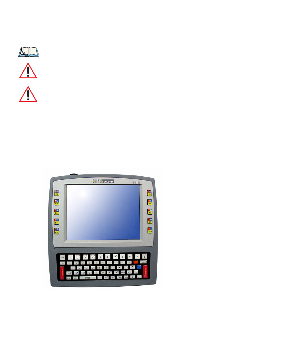
1.3 About The 8515 Vehicle-Mount Computer
The 8515 is a ruggedized vehicle-mount computer, running the Microsoft Windows Embedded CE 5.0 operating system. It is intended for use in commercial and industrial applications
with a focus on real time wireless data transactions. A wide range of data input capabilities
are supported through a variety of imager, RFID and bar code scanner options.
Figure 1.1 8515 With Qwerty Keyboard
4 Psion Teklogix 8515 Vehicle-Mount Computer User Manual
Page 25

BASIC CHECKOUT 2
2.1 Preparing The 8515 For Operation . ..........................7
2.2 8515 Safety Instructions . ................................7
2.3 Important Operating Instructions ............................8
2.4 Switching The 8515 On And Off............................8
2.5 Calibrating The Touchscreen ..............................9
2.6 Configuring Your IEEE 802.11 Radio..........................9
2.7 Setting Up The Model RA2040 802.11g Radio . . ...................9
2.7.1 Assigning An IP Address............................15
2.7.2 Name Servers Tab................................16
2.7.3 Advanced Features ...............................16
2.7.3.1 Rearranging Preferred Networks....................17
2.7.3.2 Deleting A Preferred Network.....................17
2.7.3.3 Changing Network Properties.....................17
2.8 Setting Up The Model RA2041 Radio SCU . . . ..................17
2.8.1 Assigning The IP Address............................18
2.8.2 Using The SCU To Connect To The WLAN..................18
2.9 SCU Tabs .......................................20
2.9.1 Main Tab ....................................20
2.9.2 Config Tab....................................21
2.9.2.1 SCU Security Capabilities.......................23
2.9.2.2 EAP Credentials............................25
2.9.2.3 ThirdPartyConfig............................25
2.9.3 Global Settings Tab...............................25
2.9.4 Status Tab....................................28
2.9.5 Diags Tab....................................28
2.10 Resetting The 8515 Vehicle-Mount Computer . . ..................29
Psion Teklogix 8515 Vehicle-Mount Computer User Manual 5
Page 26

6 Psion Teklogix 8515 Vehicle-Mount Computer User Manual
Page 27

2.1 Preparing The 8515 For Operation
Typically the 8515 Vehicle-Mount Computer is configured at the factory and arrives ready
for use. Although the 8515 is equipped with an internal Compact Flash slot and a Micro-SD
I/O slot, these slots are not intended for user modification. If a device needs to be changed or
added in these slots, contact qualified Psion Teklogix personnel. Refer to Appendix A:
“Support Services / Worldwide Offices” for the service number closest to you.
2.2 8515 Safety Instructions
• The cord should be installed in the vehicle so that it is not subjected to damage or stress.
• Use of a power cord that is not recommended or sold by the manufacturer may result in
fire, electric shock, or personal injury.
• An extension cord should not be used unless absolutely necessary. Use of an improper
extension cord could result in fire or electric shock. If an extension cord must be used,
make sure:
- The plug pins on the extension cord are the same number, size, and shape as those on
the adaptor.
- The extension cord is properly wired and in good electrical condition and that the
wire size is larger than 16 AWG.
• When the unit is connected to the battery or AC adaptor, the mains power cord shall
comply with National safety regulations of the country where the equipment is to
be used.
• Do not use the AC adaptor with a damaged cord or plug. Replace it immediately.
• Do not operate the AC adaptor if it has received a sharp blow, been dropped, or otherwise damaged in any way; it should be inspected by qualified service personnel.
• Do not disassemble the AC adaptor; it should be repaired by qualified service personnel.
Incorrect reassembly may result in electric shock or fire.
• To reduce risk of electric shock, unplug the battery or AC adaptor from the outlet before
attempting any maintenance or cleaning.
• Do not expose the battery or AC adaptor to rain or snow.
Preparing The 8515 For Operation
Chapter 2: Basic Checkout
Psion Teklogix 8515 Vehicle-Mount Computer User Manual 7
Page 28
Chapter 2: Basic Checkout
Important Operating Instructions
2.3 Important Operating Instructions
Warning: IT IS CRITICAL that this information be reviewed and that any guidelines
applicable to your vehicle-mount be strictly followed.
Backup Battery
The vehicle-mount backup battery provides one hour of memory backup. The capacity is
reduced as the operating temperature cools. The table below provides a general outline of
battery capacity based on the operating temperature. Charging of the backup battery will
occur between 0° C and 40° C.
Note: If the backup battery temperature is less than 10° C and a brown-out occurs,
the display backlight will switch off in order to maintain vehicle-mount operations. The backlight will switch back on when external power is restored or
the battery temperature is above 10° C.
Ta b l e 2 . 1 B a c k up B a t te r y Pe r f o rm a n c e
Temperature Backup Battery Capacity
° C (-4° F) 65%
-20
-10
° C (14° F) 80%
0
° C (32° F) close to 90%
Warning: Do not install the 8515 in such a way that the power cable is bent 90
degrees as this may damage the power cable and power cable strain relief.
2.4 Switching The 8515 On And Off
• To switch on the 8515, press the [ENTER/ON] key.
Note: If the 8515 is in suspend state, pressing [ENTER/ON] ‘wakes’ the unit from
this state. The screen in which you were working before the computer entered
suspend state is displayed.
To switch off the 8515:
• Press the [BLUE] key, and then press the [ENTER/ON] key.
Turning off the 8515 does not
saving, “suspend” state. When the 8515 is turned on from suspend state, operation resumes
within a few seconds.
8 Psion Teklogix 8515 Vehicle-Mount Computer User Manual
result in a complete reboot; rather, the unit enters a power-
Page 29

Important: If the word ‘BLUE’ is displayed in uppercase in the taskbar at the bottom of
the screen, this key is locked ‘on’—the 8515 will not switch off. Press the
[BLUE] key again to unlock it; then press [BLUE] [ENTER/ON] to switch
the 8515 off.
If, however, you’ve disabled the “Blue Key” in the ‘One Shot’ dialog box
(see “One Shots” on page 74), the 8515 can be turned off even when the
[BLUE] key is locked ‘on’.
2.5 Calibrating The Touchscreen
Before using your 8515, you will need to calibrate the touchscreen. Refer to “Calibrating
The Touchscreen” on page 38 for details.
2.6 Configuring Your IEEE 802.11 Radio
If your 8515 is equipped with a Model RA2040 radio (Marvell-88W8300 802.11g PC Card
radio), follow the steps outlined in Section 2.7: “Setting Up The Model RA2040 802.11g
Radio”.
If your vehicle-mount is equipped with a Model RA2041 radio (Summit DC 802.11 SC CF
radio), follow the steps under “Setting Up The Model RA2041 Radio SCU” on page 17 to
set up this type of radio for communication with a wireless LAN.
Chapter 2: Basic Checkout
Calibrating The Touchscreen
2.7 Setting Up The Model RA2040 802.11g Radio
The most common Marvell-88W8300 802.11g radio settings are configured as defaults.
However, there are some fields that must be completed, including the SSID of your access
point and the security methods implemented in the network (including access keys).
Important: If the 8515 is equipped with a radio that has never been configured, the
radio settings dialog box opens automatically when the unit is powered on.
In this case, skip to Step 4 on page 11.
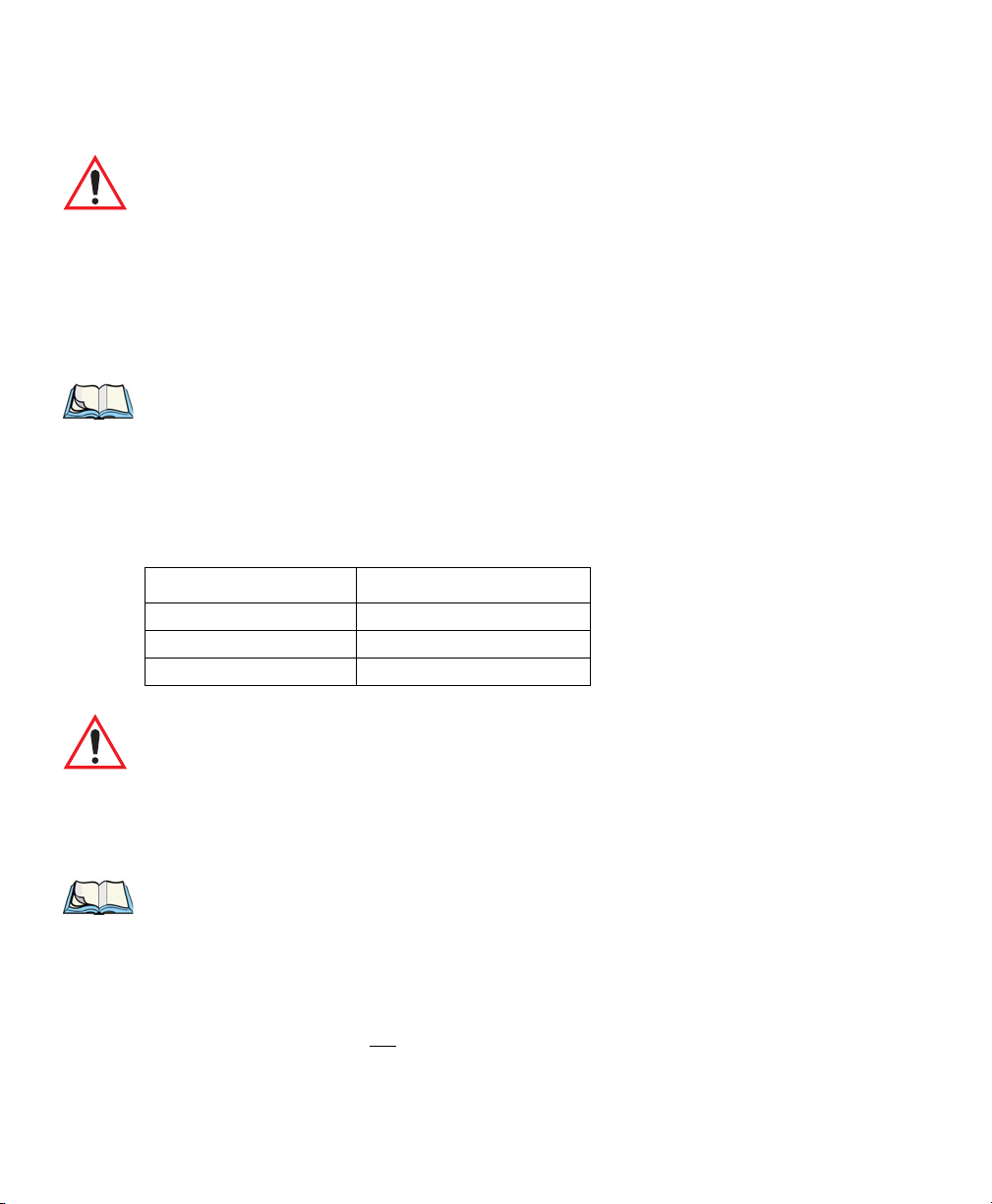
To configure the 802.11g radio:
1. Tap on Start>Settings>Network and Dial-up Connections.
Psion Teklogix 8515 Vehicle-Mount Computer User Manual 9
Page 30
Chapter 2: Basic Checkout
Setting Up The Model RA2040 802.11g Radio
Figure 2.1 Network And Dial-Up Connections
Note: You can press [CTRL] [ESC] to display the Start Menu.
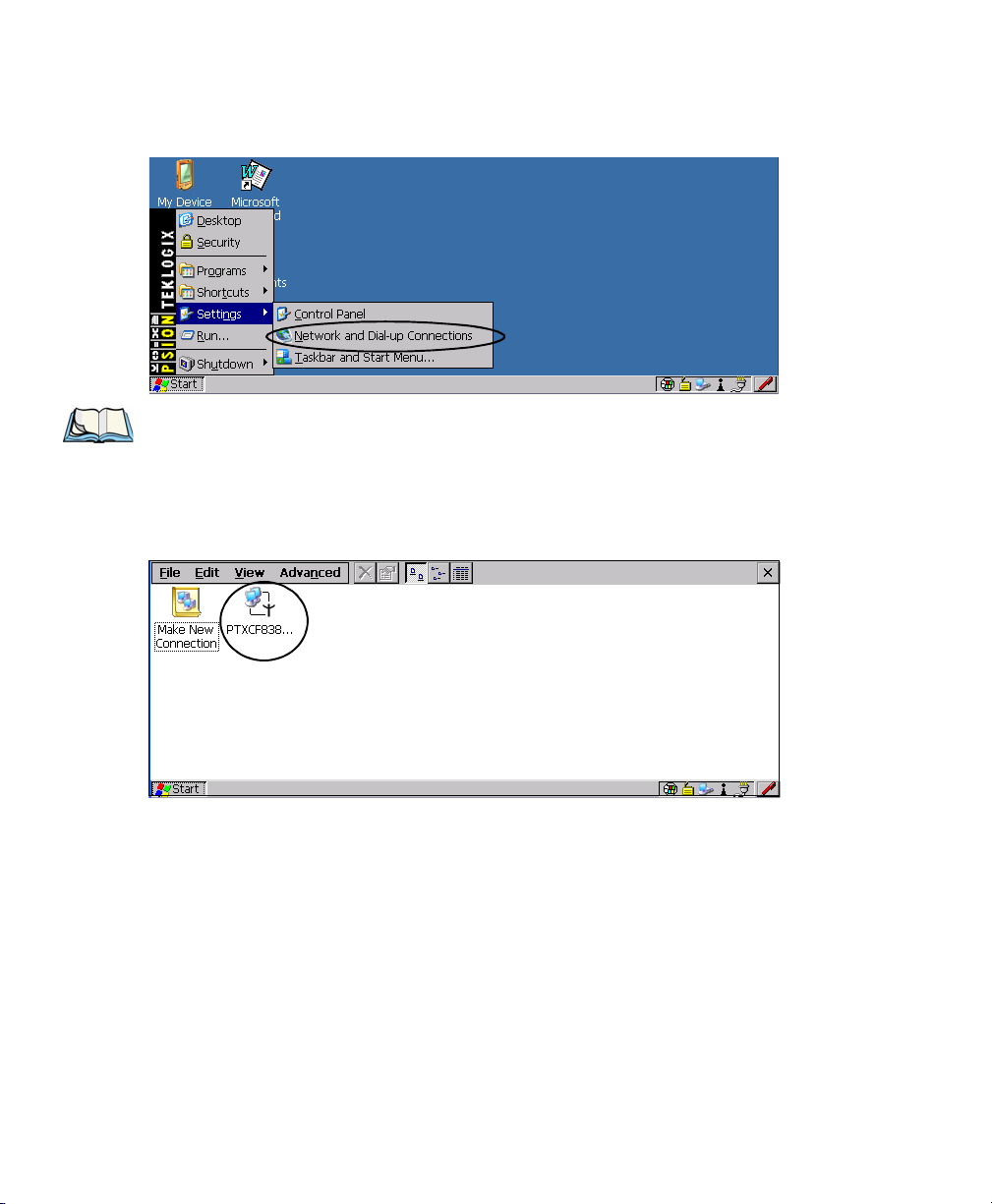
2. Choose the radio icon to open the Wireless LAN Settings window—in the sample
screen below, this is labelled PTXCF838.
Figure 2.2 Wireless Settings Window
3. Wireless Statistics Tab
This tab lists your radio statistics. When you choose the Wireless LAN icon, a
Wireless Statistics window is displayed.
10 Psion Teklogix 8515 Vehicle-Mount Computer User Manual
Page 31

Setting Up The Model RA2040 802.11g Radio
Figure 2.3 Wireless Statistics
Chapter 2: Basic Checkout
Choosing the Zero button resets the statistics of the last four items—Packets IN, Packets
OUT, IN errors and OUT errors.
Tap the stylus on the Wireless Information tab.
4. Wireless Information Tab
This tab displays existing networks to which you can connect, and it allows you to
add a new network or modify the settings for an existing network.
Figure 2.4 Wireless Information Tab
Note: Connect button—To force connection to a specific, existing network, high-
light the network to which you want your 8515 to connect, and tap the Con-
nect button.
This tab lists available networks—any access points that are broadcasting an
SSID—and it lists preferred networks—networks that you have configured. Since
access points are generally secure, they will most likely not be listed here. By
Psion Teklogix 8515 Vehicle-Mount Computer User Manual 11
Page 32

Chapter 2: Basic Checkout
Setting Up The Model RA2040 802.11g Radio
default, the 8515 attempts to connect to preferred networks. This behaviour can be
changed by enabling ‘Automatically connect to non-preferred networks’ in the
Advanced dialog box (page 16).
To add a new configuration, double-tap on the Add New item listed with the networks. A blank Wireless Properties dialog box is displayed.
5. Wireless Properties
Figure 2.5 Wireless Properties Dialog Box
Network name (SSID)
Type the appropriate SSID (Service Set Identifier) in the ‘Network name (SSID):’
text entry field at the top of this dialog box.
The Network name field can contain a maximum of 32 characters. The name
assigned here is listed as a preferred network.
Important: Keep in mind that the 8515 will only communicate with access points that
are configured with the same SSID.
Ad Hoc And Infrastructure
If you are using an “Infrastructure” network (one in which 8515s must pass data
through an access point) leave the checkbox ‘This is an ad hoc network’ empty.
If you are using an Ad Hoc network—a network in which 8515s pass data directly
to other 8515s without an access point—tap on the checkbox next to ‘This is an ad
hoc network’ to enable Ad Hoc.
Encryption
WEP (Wired-Equivalent Privacy) encryption prevents others from accidentally
accessing your network. If you are not using encryption, you can choose Disabled
from the dropdown encryption menu. Otherwise, leave this field as is.
12 Psion Teklogix 8515 Vehicle-Mount Computer User Manual
Page 33

Setting Up The Model RA2040 802.11g Radio
Chapter 2: Basic Checkout
Note: WEP cannot be disabled if you are using WPA or WPA-PSK authentication.
TKIP (Temporal Key Integrity Protocol) is an encryption protocol included as part
of the IEEE 802.11 standard for wireless LANs. Designed to enhance WEP, TKIP
uses the original WEP programming but ‘wraps’ additional code at the beginning
and end to encapsulate and modify it, encrypting each data packet with a unique
encryption key.
Authentication
802.11 supports a number of subtypes of network authentication services: Open,
Shared, WPA and WPA-PSK.
Using Open authentication, any wireless station can request authentication. The
station that needs to authenticate with another wireless station sends an authentication management frame that contains the identity of the sending station. The receiving station then sends back a frame that indicates whether it recognizes the identity
of the sending station.
Using Shared authentication, each wireless station is assumed to have received a
secret shared key over a secure channel that is independent from the 802.11 wireless
network communications channel.
WPA (Wi-Fi Protected Access) uses the Temporal Key Integrity Protocol (TKIP) to
provide strong data encryption, and offers two user authentication and key management methods.
The first method of user authentication is intended for environments using a centralized Authentication Server, such as RADIUS. User authentication is based on IEEE
802.1X and mutual authentication based EAP.
In environments where a centralized Authentication Server or EAP framework is
not available, user authentication is based on a ‘Pre-Shared Key’ method—WPA-
PSK. If you are using Pre-Shared Key authentication, you will need to manually
enter a password (Master Key) in the Access Point or Wireless Router and enter the
same password in each client device that accesses the wireless network. The manually configured WPA password (Master Key) automatically starts the TKIP data
encryption process.
Network Key
This text box is used to specify a 5 or 13 ASCII character sequence or an equivalent
10 or 26 Hexadecimal digit sequence that matches the active WEP key on the
access point.
Psion Teklogix 8515 Vehicle-Mount Computer User Manual 13
Page 34

Chapter 2: Basic Checkout
Setting Up The Model RA2040 802.11g Radio
To assign a Network key, tap in the checkbox next to ‘The key is provided auto-
matically’ to remove the check mark next to this option.
Figure 2.6 Accessing Network Key And Key Index
Tap in this checkbox to remove
the checkmark. This disables this
option, providing access to the
Network Key & Key Index fields.
Key Index
This field is used to identify the WEP key.
Enter a value from 1 to 4.
Enable 802.1X authentication
“802.1X” is the IEEE standard that offers additional security for local area networks. It provides authentication for user devices attached to an Ethernet network,
whether wired or wireless. A security protocol packet such as TLS or MD5 encapsulated in an “EAP” is used in conjunction with the “802.1X” standard to authenticate users at the MAC layer. Available EAPs are listed in the dropdown menu next
to the ‘EAP’ option.
To activate “802.1X”, tap on the checkbox next to ‘Enable 802.1X authentica-
tion’, and press the [SPACE] key to enable it.
EAP Type (Extensible Authentication Protocol):
This dropdown menu lists the EAP types available on your system. The items in
this dropdown menu will vary depending on your network setup. Keep in mind also
that some authentication protocols require that you select a ‘Certificate’. By selecting the Properties button, you will be able to select a Certificate. “Certificate
Assignment” on page 90 provides a website that outlines how to create certificates
for your network.
6. Saving and exiting the radio setup.
Once you have completed your configuration, press [ENTER] or tap on OK.
14 Psion Teklogix 8515 Vehicle-Mount Computer User Manual
Page 35

The connection you created will be listed in the Wireless Information tab as a pre-
ferred network. The radio will search for the SSID and will compare the WEP and
authentication information you specified. If there is a match between your 8515 settings and the access point settings, the 8515 will communicate on the network
through the access point.
2.7.1 Assigning An IP Address
If your network is not using a DHCP server, you will need to assign an IP address.
Figure 2.7 Configuring An IP Address
Chapter 2: Basic Checkout
Assigning An IP Address
Note: Choosing the Renew button forces the 8515 to renew or find a new IP
address. This is useful if, for example, you are out of communication range for
a longer period of time and your 8515 is dropped from the network.
To define a static IP address:
• Tap the Configure button.
Figure 2.8 Defining An IP Address
• Tap on the radio button next to Specify an IP address.
Psion Teklogix 8515 Vehicle-Mount Computer User Manual 15
Page 36

Chapter 2: Basic Checkout
Name Servers Tab
• Tap on each field, and type an IP, Subnet Mask and Default Gateway address. Tap on
OK to save your information.
2.7.2 Name Servers Tab
Note: If DHCP is enabled, name server addresses are assigned automatically.
•In the IP Information tab, tap on the Configure button. (Figure 2.7 is the window from
which you choose the Configure button.)
• Tap on the Name Servers tab.
Figure 2.9 Name Servers Tab
The DNS and WINS fields in the Name Servers tab allow you to specify additional WINS
and DNS resolvers. The format for these fields is ###.###.###.###.
2.7.3 Advanced Features
To display the Advanced Wireless Settings dialog box:
• Tap the Advanced button in the Wireless Information tab.
This window lists the available preferred networks.
16 Psion Teklogix 8515 Vehicle-Mount Computer User Manual
Page 37

Figure 2.10 Advanced Wireless Settings
2.7.3.1 Rearranging Preferred Networks
The 8515 attempts to connect with the networks listed in this dialog box in sequence, beginning at the top of the list. If you need to rearrange this list of networks—move networks up
and down in the list:
• In the networks list, tap on the network that you want to move up or down in the list.
• To move the highlighted item upward or downward in the list, tap the Up or Down
button, and press [ENTER].
Setting Up The Model RA2041 Radio SCU
Chapter 2: Basic Checkout
2.7.3.2 Deleting A Preferred Network
To delete a network from this list:
• Tap on the network in the list to highlight it.
• Tap the Delete button, and press [ENTER].
2.7.3.3 Changing Network Properties
To change the properties of an existing preferred network:
• Highlight the network that you want to modify.
• Tap the Properties button, and press [ENTER].
• Make any necessary changes in the Wireless Properties dialog box, and press [ENTER]
to save the changes.
2.8 Setting Up The Model RA2041 Radio SCU
This section describes the Summit DC 802.11 SC CF radio Summit Client Utility (SCU).
The SCU provides the utilities you will need to configure the Summit 802.11g Compact
Flash radio module, model number RA2041, so that it can communicate through a wireless
LAN effectively and securely.
Psion Teklogix 8515 Vehicle-Mount Computer User Manual 17
Page 38

Chapter 2: Basic Checkout
Assigning The IP Address
Note: You do not need to reset your 8515 after configuring the Summit DC 802.11
SC (Model RA2041) CF radio.
2.8.1 Assigning The IP Address
Before launching the SCU, you need to configure how the IP address will be obtained.
• Tap on Start>Settings>Network and Dial-up Connections.
Follow the steps under the heading “Assigning An IP Address” on page 15 to determine
how the IP address will be obtained—either via DHCP or by specifying an address.
2.8.2 Using The SCU To Connect To The WLAN
This section provides a quick set of steps to create a profile (referred to as a config). Detailed
information about each of the SCU tabs—Main, Config, Status, Diags and Global Set-
tings—is provided under “SCU Tabs” beginning on page 20.
To launch the SCU so that your vehicle-mount can connect to a wireless LAN:
• Tap on Start>Programs>Summit>SCU.
Figure 2.11 SCU Main Menu
• Tap on the Config tab.
Figure 2.12 SCU Configuration Menu
Radio
Attributes
18 Psion Teklogix 8515 Vehicle-Mount Computer User Manual
Page 39

Using The SCU To Connect To The WLAN
Chapter 2: Basic Checkout
• Tap on the New button to define a new config (profile).
• Type a name for your configuration using any alpha-numeric combination to uniquely
identify this config.
• Tap on OK to return to the Config tab.
• Tap on Commit to save the config name.
• When a pop-up message indicates that your configuration will be saved, tap on OK.
To configure the SSID for the network to which you want to associate:
• Type an SSID in the text box to the right of SSID. This field is limited to 32 characters.
• Tap on Commit and then, in the pop-up message, tap on OK to save your SSID setting.
Important: To learn more about the other options available in the radio attributes list,
refer to “Config Tab” on page 21.
To configure authentication:
• Tap on the EAP type dropdown menu, and choose the appropriate type of authentication —LEAP, EAP-FAST, PEAP-MSCHAP, and PEAP-GTC.
• Next, tap on the Credentials button, and type credentials for IEEE 802.1X EAP types.
Important: Refer to “SCU Security Capabilities” on page 23 for details about security
settings. Additional EAP details are described in “EAP Credentials” on
page 25.
To configure encryption:
• Tap on the Encryption dropdown menu, and choose the appropriate type of encryp-
tion—Manual WEP, Auto WEP, WPA PSK, WPA TKIP, WPA2 PSK, WPA2 AES, and
CCKM TKIP.
If you choose Manual WEP, WPA PSK or WPA2 PSK:
• Tap on the WEP/PSK Keys button. For Manual WEP, choose up to four static WEP
keys. For PSK, type an ASCII passphrase or hex PSK.
• Configure any other settings that are supplied by the network administrator for the SSID
to which you will associate.
• Make certain that you tap on Commit following each change.
Once you’ve completed the configuration:
• Tap the Main tab. Tap on the Active Config button—your new config will be listed in
the dropdown menu.
Psion Teklogix 8515 Vehicle-Mount Computer User Manual 19
Page 40

Chapter 2: Basic Checkout
SCU Tabs
When you tap on the config you created, the Summit DC-802.11 SC CF radio module
(Model RA2041) attempts to connect to the network using these steps:
- Associate to the SSID.
- Authenticate to the network.
- If EAP authentication is being used, derive dynamic encryption keys.
- If DHCP is being used by the network, obtain an IP address.
If the Summit DC-802.11 SC CF (Model RA2041) is not connecting:
• Tap on the Status tab.
The Status dialog box lists the IP and MAC address, and indicates the current state of the
radio, the signal strength, channel etc.
You can also use the Status screen for DHCP renewal and ICMP Echo Requests (Pings).
Important: For details about the Status dialog box, refer to “Status Tab” on page 28.
2.9 SCU Tabs
This section provides a detailed description of each of the tabs available in the SCU—Main,
Config, Status, Diags and Global Settings.
2.9.1 Main Tab
The Main tab is displayed when you tap on Start>Programs>Summit>SCU.
Figure 2.13 SCU Main Menu
• Enable/Disable Radio: Enables or disables the radio. This a toggle button; when the
radio is enabled, this button reads Disable Radio, and when the radio is disabled, it reads
Enable Radio.
20 Psion Teklogix 8515 Vehicle-Mount Computer User Manual
Page 41

• Active Config: Lists the name(s) of the active configuration profile(s) which are
referred to as configs. When a config is chosen from the Active Config dropdown menu,
the settings for that config become active.
-If ThirdPartyConfig is selected, after the vehicle-mount goes through a power cycle,
WZC is used for configuration of the radio. See “ThirdPartyConfig” on page 25
for details.
• Association Status: Indicates if the radio is associated to an access point. If this is not
the case, Association Status indicates the radio status.
• Software Version: This field displays the version of the device driver and the SCU that
are running on the 8515.
• About Box: This box provides information about the SCU.
2.9.2 Config Tab
The Config tab allows you to define radio and security settings that are stored in the registry
as part of the configuration profile or config.
Figure 2.14 SCU Configuration Menu
Chapter 2: Basic Checkout
Config Tab
Radio
Attributes
The config you create and save is listed in the Active Config dropdown menu in the Main
tab. You can define up to 20 configs.
• Config: Used to choose the config to be viewed or edited. If ThirdPartyConfig is
chosen, after the 8515 goes through a power cycle, WZC is used for configuration of
the radio.
• Rename: Allows you to assign a config name.
• Delete: Deletes the config unless it is currently active.
• New: Allows you to create a new config with default settings and assign it a name.
• Commit: Saves all changes.
Psion Teklogix 8515 Vehicle-Mount Computer User Manual 21
Page 42

Chapter 2: Basic Checkout
Config Tab
• Radio Attributes: Lists radio attributes. These attributes can be individually chosen
from this menu. When an attribute is chosen, an associated list of options is displayed
where you can assign new settings or view existing settings.
The following table describes the options in the Radio Attributes dropdown menu:
Table 2.2 Radio Attributes Menu
Radio
Attribute
Config Name of config (configuration pro-
Description Value Default
Maximum of 32 characters. None
file). Use Rename button to
change name.
SSID Service set identifier (SSID) for
Maximum of 32 characters. None
WLAN to which the radio connects.
Client Name Name assigned to radio & vehicle-
Maximum of 16 characters. None
mount into which it is installed.
Power Save Power save mode for radio. CAM: Constantly awake.
Maximum: Maximum
power savings.
Fast: Fast power save mode.
Tx Power Maximum transmit power. Max: Maximum defined for
current regulatory domain.
Measured in mW: 50,30,10, 1.
Bit Rate Used by radio when interacting with
WLAN access point.
Auto: Rate automatically
negotiated with access point.
Rates in Mbps: 1, 2, 5.5, 6.9,
11, 12, 18, 24, 36, 48, 54.
Radio Mode Used by 802.11g when interacting
with access point.
B rates only: 1, 2, 5.5, &
11 Mbps.
G rates only: 6, 9, 12, 18, 24,
36, 48, and 54 Mbps.
BG rates full: All B and
G rates.
BG rates optimized: 1, 2, 5.5,
6, 11, 24, 36 & 54 Mbps.
Fast
Max
Auto
BG rates
optimized
Auth Type 802.11 authentication type used
when associating with access point.
22 Psion Teklogix 8515 Vehicle-Mount Computer User Manual
Open, shared-key, or LEAP
(Network-EAP).
Open
Page 43

Table 2.2 Radio Attributes Menu
Chapter 2: Basic Checkout
Config Tab
Radio
Attribute
EAP Type Extensible Authentication Protocol
type used for 802.1X authentication
to access point.
Credentials Authentication credentials for the
selected EAP type.
Refer to “EAP Credentials” on page
25.
Encryption Type of encryption used to protect
transmitted data.
Description Value Default
None, LEAP, EAP-FAST,
PEAP-MSCHAP
– To use EAP-TLS, you must
use WZC.
User: Username or
Domain/Username (up to 64
characters).
Password: up to 64 characters.
For PEAP: CA Cert–CA
server certificate filename.
Off, Manual WEP, Auto WEP
(generated during EAP
authentication), WPA-PSK,
WPA-TKIP, WPA2-PSK,
WPA2-TKIP, WPA2-AES,
CCKM-TKIP.
For Manual WEP: Up to four
static WEP keys.
For PSK: ASCII passphrase or
hex PSK.
None
None
None
• EAP-Type & Encryption: Security settings. These settings allow you to enhance the
security of data across the wireless LAN. Refer to “EAP Credentials” on page 25 and
“SCU Security Capabilities” on page 23 for details about these settings.
2.9.2.1 SCU Security Capabilities
The SCU provides integrated security to protect transmitted data as well as the vehiclemount infrastructure that transmits and receives data.
A foundational element of the IEEE 802.11i WLAN security standard is IEEE 802.1X and a
critical application on a mobile device is an 802.1X supplicant. This supplicant provides an
interface between the radio and the operating system and supports the authentication and encryption elements required for 802.11i, also known as Wi-Fi Protected Access 2 (WPA2), as
well as predecessors such as WPA and WEP. Summit software includes an integrated supplicant that supports a broad range of security capabilities, including:
Psion Teklogix 8515 Vehicle-Mount Computer User Manual 23
Page 44

Chapter 2: Basic Checkout
Config Tab
• 802.1X authentication using pre-shared keys or an EAP type, required for WPA2
and WPA.
• Data encryption and decryption using WPA2 AES, WPA TKIP or WEP.
Common EAP types include:
• EAP-TLS: Uses the same technology as a follow-on to Secure Socket Layer (SSL). It
provides strong security, but relies on client certificates for user authentication.
• PEAP: Provides secure user authentication by using a TLS tunnel to encrypt EAP traffic. Two different inner methods are used with PEAP:
- EAP-MSCHAPV2, resulting in PEAP-MSCHAP: This is appropriate for use against
Windows Active Directory and domains.
- EAP-GTC, resulting in PEAP-GTC: This is for authentication with one-time pass-
words (OTPs) against OTP databases such as SecureID.
• LEAP: Is an authentication method for use with Cisco WLAN access points. LEAP
does not require the use of server or client certificates. LEAP supports Windows Active
Directory and domains but requires the use of strong passwords to avoid vulnerability to
offline dictionary attacks.
• EAP-FAST: Is a successor to LEAP and does not require strong passwords to protect
against offline dictionary attacks. Like LEAP, EAP-FAST does not require the use of
server or client certificates and supports Windows Active Directory and domains.
Note: PEAP and EAP-TLS require the use of Windows facilities for the configura-
tion of digital certificates.
SCU EAP Types
The following EAP types are supported by the integrated supplicant and can be configured
in SCU: PEAP-MSCHAP, PEAP-GTC, LEAP and EAP-FAST. With each of these four
types, if authentication credentials are not stored in the config, you will be prompted to enter
credentials the first time the radio attempts to associate to an access point that supports
802.1X (EAP).
Consider the following when configuring one of the EAP types:
• PEAP-GTC: SCU supports static (login) passwords only.
• LEAP: Strong passwords are recommended.
• EAP-FAST: SCU supports automatic, not manual, PAC provisioning.
EAP-TLS will work with a Summit DC-802.11 SC CF (Model RA2041) radio module
when Windows Zero Config (WZC) rather than the SCU is used to configure the type. With
WZC, the native Windows supplicant instead of the SCU integrated supplicant is used.
24 Psion Teklogix 8515 Vehicle-Mount Computer User Manual
Page 45

2.9.2.2 EAP Credentials
Keep the following in mind when defining security settings:
• If the credentials specified in the config are incorrect and that config is used, the authen-
tication fails without an error message; you will not be prompted to enter
correct credentials.
• If the credentials are not specified in the config, when the radio tries to associate using
that config, you will be prompted to enter the credentials.
• When prompted, you can enter valid credentials, enter invalid credentials, or cancel
the operation.
- If you enter valid credentials and tap OK, the radio will associate and authenticate.
- If you enter invalid credentials and tap on OK, the radio will associate but will not
authenticate; you will be prompted again to enter credentials.
- If you tap on Cancel or clear the credentials fields and tap on OK, the radio will not
attempt to associate with that config until you perform one of the following actions
(while the config is the active config):
- Cause the vehicle-mount to go through a power cycle or suspend/resume.
- Disable and enable the radio, or tap the Reconnect button on the Diags windows.
- Modify the config, and tap on Commit.
Alternatively, you can choose another config as the active config and then switch back to the
config for which EAP authentication was cancelled.
Chapter 2: Basic Checkout
Global Settings Tab
2.9.2.3 ThirdPartyConfig
If you choose to configure ThirdPartyConfig, the SCU will work with the operating sys-
tem’s Windows Zero Config (WZC) to configure radio and security settings for the CF radio
installed in the unit.
Choosing this config means that WZC must be used to define the following radio and security options: SSID, Auth Type, EAP Type and Encryption.The SCU settings for ThirdParty-
Config include: Client Name, Power Save, Tx Power, Bit Rate and Radio Mode. These SCU
settings along with SCU global settings and the WZC settings will be applied to the
radio module.
2.9.3 Global Settings Tab
The Global Settings tab allows you to define radio and security settings that apply to all
configs (profiles), along with settings that apply specifically to the SCU.
Psion Teklogix 8515 Vehicle-Mount Computer User Manual 25
Page 46

Chapter 2: Basic Checkout
Global Settings Tab
Figure 2.15 SCU Global Settings Menu
The Global Settings outlined in the table below can be edited in the SCU:
Ta b l e 2 . 3 G l o b al S e t ti n g s M e n u
Global Setting Description Value Default
CCX features Activates three CCX features:
On, Off Off
AP-assisted roaming, AP-specified maximum transmit power
and radio management.
Cert Path Directory where certificates for
EAP authentication are stored.
Frag Thresh Packet is fragmented when
Valid directory path up to
64 characters.
Dependent
on device.
Integer from 256 to 2346 2346
packet size (in bytes) exceeds
threshold.
G Shortslot 802.11g short slot timing mode. Auto, Off, On Auto
Hide Passwords On - SCU as well as EAP authen-
On, Off Off
tication dialog boxes hide passwords, WEP keys and other
sensitive information.
LED Available only with MCF10G. On, Off Off
Preamble Type of radio preamble
Auto, Short, Long Auto
or headers.
Ping Payload Amount of data to be transmitted
on a ping.
Bytes: 32, 64, 128, 256, 512
and 1024
32
26 Psion Teklogix 8515 Vehicle-Mount Computer User Manual
Page 47

Chapter 2: Basic Checkout
Global Settings Tab
Ta b l e 2 . 3 G l o b al S e t ti n g s M e n u
Global Setting Description Value Default
Ping Timeout msAmount of time in milliseconds
that passes without a response
before ping request is considered
a failure.
Ping Delays ms Amount of time in milliseconds
between successive ping
requests.
Roam Delta Amount by which second AP’s
RSSI must exceed the moving
average RSSI for the current AP
before the radio will attempt to
roam to a second AP.
Roam Period Following an association or roam
scan (with no roam), the number
of seconds the radio collects
RSSI scan data before considering roaming.
Roam Trigger If RSSI from AP is less than roam
trigger value, radio performs
roam scan or probes for an AP
with stronger signal.
RTS Thresh Packet size above which
RTS/CTS is required on link.
Integer from 0 to 30000 5000
Integer from 0 to 7200000 1000
dBm: 5, 10, 15, 20, 25, 30, 35 15
Seconds: 5, 10, 15, 20, 25, 30,
10
35, 40, 45, 50, 55, 60
dBm: -50, -55, -60, -65,
-70
-70, -75
An integer from 0 to 2347 2347
RX Diversity Defines how to handle antenna
diversity when receiving data
from AP.
Psion Teklogix 8515 Vehicle-Mount Computer User Manual 27
-On-Start on Main: On startup,
use main antenna.
-On-Start on Aux: On startup,
use auxiliary antenna.
-Main only: Use main
antenna only.
-Aux only: Use auxiliary
antenna only.
On-Start on
Main
Page 48

Chapter 2: Basic Checkout
Status Tab
Ta b l e 2 . 3 G l o b al S e t ti n g s M e n u
Global Setting Description Value Default
TX Diversity Defines how to handle antenna
WMM Use Wi-Fi Multimedia Exten-
2.9.4 Status Tab
Figure 2.16 SCU Status Menu
The Status tab provides status information including IP address and MAC address for the
client radio, IP address and MAC address for the AP, signal strength, channel, transmit
power and data rate.
diversity when transmitting data
to AP.
sions, also know as WMM.
-Main only: Use main
On
antenna only.
-Aux only: Use auxiliary
antenna only.
-On: Use diversity.
On, Off Off
2.9.5 Diags Tab
Figure 2.17 SCU Diagnostics Menu
Ping Addre ss
Ping Results
Use the Diags tab as a troubleshooting tool. The functions are as follows:
28 Psion Teklogix 8515 Vehicle-Mount Computer User Manual
Page 49

Resetting The 8515 Vehicle-Mount Computer
• (Re)Connect: Enables/Disables the radio, applies/reapplies current config and tries to
associate and authenticate to the wireless LAN, logging all activity in the output area at
bottom of the dialog box.
• Release/Renew: Obtains a new IP address through DHCP and logs all activity in the
output area.
• Start Ping/Stop Ping: Starts a continuous ping to the address in the text box next to this
button. This a toggle button so when you tap on it, it changes to Stop Ping. Closing this
window or tapping on another button also stops the ping.
• Diagnostics: Attempts to connect or reconnect to an AP, and provides a more detailed
dump of data than if you used (Re)connect. The dump includes the radio state, config
settings, global settings and BSSID list of APs. The SCU is saved to a file called
_sdc_diag.txt in the Windows directory.
2.10 Resetting The 8515 Vehicle-Mount Computer
Warm Reset
To execute a warm reset:
• Press and hold down the [BLUE] key and the [ENTER/ON] key simultaneously for a
minimum of six seconds.
A warm reset closes open applications; any unsaved data is lost. Installed programs and
saved data are preserved.
Chapter 2: Basic Checkout
Note: You do not need to reset your 8515 after configuring the radio.
Cold Reset
There are two options when executing a cold reset: reset to BootLoader, or reset directly to
Windows Embedded CE 5.0 operating system.
To execute a cold reset and access the BooSt menu:
• Press and hold down the [BLUE] key, the [ENTER] key and the [SPACE] key simultaneously for a minimum of six seconds.
After a cold reset, the BooSt menu appears.
• If you want to load the Windows Embedded CE 5.0 operating system, type 1.
• If you want a clean start, press ! (that is, [SHIFT] [1]). All data and settings are lost.
Files and data stored in flash are preserved.
Once the OS loads, any executables and cab files in the startup folders are run. The cab files
are deleted by the cab file installer unless they are marked read-only.
Psion Teklogix 8515 Vehicle-Mount Computer User Manual 29
Page 50

Page 51

GETTING TO KNOW THE 8515 3
3.1 Features Of The 8515 . . ...............................33
3.2 The Internal Backup Battery..............................34
3.3 The Stylus.......................................34
3.4 The Keyboard.....................................34
3.4.1 Modifier Keys..................................34
3.4.1.1 Activating Modifier Keys.......................34
3.4.1.2 Locking Modifier Keys ........................35
3.4.2 The Keys ....................................35
3.5 Function Keys And Macro Keys ...........................36
3.5.1 Function Keys..................................36
3.5.2 Macro Keys...................................37
3.5.3 The Keypad Backlight .............................38
3.6 The Display ......................................38
3.6.1 Calibrating The Touchscreen..........................38
3.7 8515 Indicators.....................................39
3.7.1 Power Indicator LED..............................39
3.7.2 Onscreen Indicators...............................39
3.7.3 Audio Indicators.................................41
3.8 Scanning........................................41
3.8.1 Scanning Techniques..............................41
3.8.2 Scan LED Indicators ..............................41
3.8.3 Troubleshooting . . ...............................42
3.8.4 Operating One Dimensional (1D) Laser Scanners...............42
3.8.5 Operating PDF Laser Scanners.........................42
3.9 Monitoring The Network Connection.........................42
3.10 Connecting An 8515 To A Windows 2000 Or XP PC ................43
3.11 Connecting An 8515 To A Windows Vista™ PC ..................43
3.12 General Maintenance.................................43
Psion Teklogix 8515 Vehicle-Mount Computer User Manual 31
Page 52

3.12.1 Ports.......................................43
3.12.2 Caring For The Touchscreen..........................44
3.12.3 Cleaning The 8515 ...............................44
32 Psion Teklogix 8515 Vehicle-Mount Computer User Manual
Page 53

3.1 Features Of The 8515
Figure 3.1 Front Of The 8515 Vehicle-Mount Computer
Antenna
Chapter 3: Getting To Know The 8515
Features Of The 8515
Function Keys
Beeper
Figure 3.2 8515 Ports
Function Keys
Power LED
Macro Keys
Enhanced USB Host Ports Speaker/Mic Jack
(for external devices, console)
USB Device Port
Psion Teklogix 8515 Vehicle-Mount Computer User Manual 33
UART (DB-9) Port
Page 54

Chapter 3: Getting To Know The 8515
The Internal Backup Battery
3.2 The Internal Backup Battery
The 8515 vehicle-mount is equipped with an internal battery that will provide backup power
to the unit for up to 30 seconds of normal operation. The display will be blank during this
time. After 30 seconds, the unit will shut off to preserve the contents of RAM. The backup
battery provides one hour of memory backup. For configuration information, please see
“Power Properties” on page 82; for specifications, see “Internal Lithium-Polymer Battery”
on page 145.
The backup battery is not
personnel.
3.3 The Stylus
The stylus is supplied with a holder with double-sided adhesive tape so that it can be attached wherever is most convenient for you.
3.4 The Keyboard
The 8515 provides a 58-key QWERTY or ABC alphanumeric keyboard layout (see Figure
3.1 on page 33).
Most of the keys on these keyboards operate much like a desktop computer. If a key or key
function is not consistent with the PC keyboard, the differences are noted.
Note: A soft keyboard that is a replica of the external keyboard is available. Refer to
“Input Panel” on page 105 for details.
3.4.1 Modifier Keys
The [SHIFT], [CTRL], [ALT], [BLUE] ad [ORANGE] keys are modifier keys. Pressing a
modifier key changes the function of the next key pressed. For example, a square bracket is
printed in orange print above the [4] key. Pressing the [ORANGE] key followed by the [4]
key displays a square bracket rather than the number 4.
The [SHIFT], [CTRL] and [ALT] keys operate much like a desktop keyboard except that
they are not chorded (two keys held down simultaneously). The modifier key must be
pressed first followed by the key whose function you want modified.
user accessible. It must be replaced by authorized Psion Teklogix
3.4.1.1 Activating Modifier Keys
When a modifier key is pressed once, it is displayed in lowercase letters in the taskbar at the
bottom of the 8515 screen. For example, if the [CTRL] key is pressed, ctrl key is displayed at the bottom of the unit screen. Once another key is pressed, the modifier key
becomes inactive and disappears from the taskbar.
34 Psion Teklogix 8515 Vehicle-Mount Computer User Manual
Page 55

3.4.1.2 Locking Modifier Keys
When a modifier key is pressed twice, it is ‘locked’ on. A ‘locked’ modifier key is displayed
in uppercase letters in the taskbar. For example, pressing the [BLUE] key twice locks it
on—it is displayed as BLUE KEY in the taskbar at the bottom of the computer screen.
The locked modifier key will remain active until it is pressed a third time to unlock or turn it
off. Once a modifier key is unlocked (pressed a third time), the uppercase representation at
the bottom of the screen is no longer displayed.
Note: The locking function of modifier keys can be disabled so that pressing a modi-
fier key once will lock the key ‘on’. If you disable the ‘One Shot’ function of
these keys, pressing a modifier key once will lock it ‘on’. Pressing the same
key a second time will unlock or turn it ‘off’. Refer to “One Shots” on page 74
for details.
3.4.2 The Keys
The [BLUE] And [ORANGE] Keys
The [BLUE] and [ORANGE] modifier keys provide access to additional symbols and keys.
These additional symbols and keys are colour coded in blue and orange print above the key-
board keys.
Press the [BLUE] key to access functions or characters displayed in blue print on the keyboard. Press the [ORANGE] key to access functions or characters displayed in orange print
on the keyboard.
Chapter 3: Getting To Know The 8515
The Keys
The [SHIFT/CAPS] Key
The [SHIFT/CAPS] key is used to display uppercase alpha characters. Pressing
[BLUE][SHIFT] turns the [CAPS] key on so that all alpha characters are printed in uppercase until the [BLUE][SHIFT] sequence is pressed again.
The Arrow Keys
The Arrow keys move the cursor around the screen in the direction of the arrow—up, down,
left and right. The cursor is the flashing box or underline character that indicates where the
next character you type will appear.
The [INS] Key
The [INS] key inserts a character at the cursor position.
The [DEL] Key
The [DEL] key erases the character at the cursor position.
Psion Teklogix 8515 Vehicle-Mount Computer User Manual 35
Page 56

Chapter 3: Getting To Know The 8515
Function Keys And Macro Keys
The [BKSP] Key
The [BKSP] key (sometimes referred to as destructive backspace) moves the cursor one
character to the left, erasing the incorrectly entered key stroke.
The [CTRL] And [ALT] Key
The [CTRL] and [ALT] keys modify the function of the next key pressed and are application
dependent.
The [TAB] Key
Typically, the [TAB] key moves the cursor to the next field to the right or downward.
The [ESC] Key
Generally, this key is used as a keyboard shortcut to close the current menu, dialog box or
activity and return to the previous one.
The [SPACE] Key
Pressing this key inserts a blank space between characters. In a Windows dialog box, pressing the [SPACE] key enables or disables a checkbox.
The [HOME] Key
The [HOME] key moves the cursor to the top of the form or page.
The [END] Key
The [END] key moves the cursor to the bottom of the form or page.
The [PgUp] And [PgDn] Keys
The [PgUp] key displays the previous screen of information. The [PgDn] key displays the
next screen of information.
3.5 Function Keys And Macro Keys
In addition to the standard keyboard functions (see “The Keyboard” on page 34), 8515
Vehicle-Mount Computers are equipped with function keys and macro keys.
3.5.1 Function Keys
The 8515 is equipped with a series of 30 function keys divided amongst 10 physical keys,
each of which is defined in the application software. There are five keys located on each side
of the display.
36 Psion Teklogix 8515 Vehicle-Mount Computer User Manual
Page 57

Accessing Function Keys [F1] to [F10]
Function keys [F1] to [F10] can be directly accessed by pressing the function keys labelled
in yellow along the sides of the display. No key combination is required. Function keys [F1]
to [F5] are located to the left of the display, [F6] to [F10] on the right.
Accessing Function Keys [F11] To [F20]
These keys are labelled in orange in the top-left corner of the function keys. To access these
keys, press the [ORANGE] key followed by [F1] to [F10].
• To access function key [F11], press the [ORANGE] key followed by [F1].
• Press [ORANGE] [F2] to access function key [F12], etc.
Accessing Function Keys [F21] To [F30]
These keys are labelled in blue in the top-right corner of the function keys. To access these
keys, press the [BLUE] key followed by [F1] to [F10].
• To access function key [F21], press the [BLUE] key followed by [F1].
• Press [BLUE] [F2] to access Function key [F22], etc.
3.5.2 Macro Keys
Important: Refer to “Macro Keys” on page 75 for details about creating macros.
Chapter 3: Getting To Know The 8515
Macro Keys
8515 Vehicle-Mount Computers are equipped with six macro keys that can be programmed
to replace frequently used keystrokes, along with the function of executable keys such as the
[ENTER] key, the [BKSP] key, any function key and arrow key, etc.
Macro Keys [M1] And [M2]
These keys are displayed in black print on the bottom row of executable keys on the key-
board. These macro keys are accessed by simply pressing the key.
Macro Keys [M3] To [M6]
These keys are displayed in blue print on the [M1] and [M2] keys in the bottom row of exe-
cutable keys, and on the [N] and [M] keys in the first row of alpha keys on the keyboard. To
access these macro keys, press the [BLUE] key followed by the appropriate executable or
alpha key. For example, on a Qwerty keyboard:
• Press [BLUE] [N] to access macro key [M5].
• To access [M3], press [BLUE] [M1], etc.
Psion Teklogix 8515 Vehicle-Mount Computer User Manual 37
Page 58

Chapter 3: Getting To Know The 8515
The Keypad Backlight
3.5.3 The Keypad Backlight
The intensity of the keypad backlight and the conditions under which this backlight is activated can be configured using the Keyboard icon in the Control Panel. The behaviour of the
keypad backlight is tailored in the Keyboard Properties dialog box.
Note: Refer to “Backlight” on page 73 for details about this option. Keep in mind
that this option may be restricted to supervisory use only.
3.6 The Display
8515s are equipped with display backlighting to improve character visibility in low light
conditions. The backlight switches on when a key is pressed or the touchscreen is tapped.
The backlight intensity and the duration of time that the backlight will remain at full intensity can be specified in the Display Properties dialog box in the Control Panel.
Note: Refer to “Display Backlight” on page 71 for details about the Display Prop-
erties dialog box.
3.6.1 Calibrating The Touchscreen
If your 8515 touchscreen has never been calibrated or if you find that the stylus pointer is
not accurate when you tap on an item, use the Stylus Properties dialog box in the Control
Panel to recalibrate the screen.
•In the Control Panel, choose the Stylus icon to display the Stylus Properties window.
Figure 3.3 Control Panel: Stylus Icon
• Choose the Calibration tab, and then tap on the Recalibrate button.
38 Psion Teklogix 8515 Vehicle-Mount Computer User Manual
Page 59

Figure 3.4 Stylus Properties Menu: Calibration Tab
• Follow the directions on the calibration screen to calibrate the screen.
3.7 8515 Indicators
8515s use onscreen messages and audio tones as indicators. The vehicle-mount is also
equipped with a power indicator LED.
3.7.1 Power Indicator LED
A power indicator LED is located in the keyboard on the front of the unit. When the vehiclemount is receiving power from an external source, the green power indicator LED is illuminated. When the unit is in suspend, the LED remains on but is flashing.
Chapter 3: Getting To Know The 8515
8515 Indicators
3.7.2 Onscreen Indicators
The taskbar at the bottom of the screen displays a variety of system status indicators.
Figure 3.5 Taskbar
The taskbar changes dynamically, and only those icons that are applicable are displayed. For
example, if a radio is not installed in your 8515, the radio signal icon is not displayed in
the taskbar.
Psion Teklogix 8515 Vehicle-Mount Computer User Manual 39
Page 60

Chapter 3: Getting To Know The 8515
Onscreen Indicators
Windows Start Button
You can display the Start Menu by tapping on the Start button in the taskbar.
Modifier Key Indicators
[SHIFT], [CTRL], [ALT], [BLUE] and [ORANGE] are modifier keys that have onscreen
indicators to show when a key is active or locked. If a modifier key is pressed once to activate it, the key is displayed in the taskbar in lowercase characters—for example, pressing
the [BLUE] key once displays
‘locked on’ and the onscreen indicator is displayed in uppercase letters in the taskbar—for
example, pressing [BLUE] twice displays
802.11 Radio Signal Quality
Increasing radio signal quality is represented by longer, filled bars within this icon.
blue key in the taskbar. If a modifier key is pressed twice, it is
BLUE KEY in the taskbar.
Good No Radio
Reception
Weak
Reception Link
The radio signal is determined when the 8515 receives a message. If the unit receives no
messages within a second, the “no signal” icon is displayed. The signal strength icon shows
the following cases: No signal, 1% to 25% bar, 26% to 50% bar, 51% to 75% bar and 75%
to 100% bar.
Bluetooth Radio
This icon represents the Bluetooth radio installed in your 8515.
Security Level
Security levels can be set to limit user access to 8515 settings. In addition, applications can
be restricted to prevent inadvertent changes.
External Power
This is the external power icon displayed in the taskbar.
External Devices
When a peripheral is attached to the USB or serial ports and activated, an associated icon
appears in the taskbar.
Scanner RFID Serial DeviceUSB Device
40 Psion Teklogix 8515 Vehicle-Mount Computer User Manual
Page 61

3.7.3 Audio Indicators
The 8515 beeper provides a variety of sounds and can be configured to emit a sound when a
key is pressed, a keyboard character is rejected, scan input is accepted or rejected or an operator’s entry does not match in a match field.
Note: Refer to “Volume And Sound Properties” on page 81 for details about the Vol-
ume & Sound Properties dialog box.
3.8 Scanning
Decoded scanners must be configured by scanning special configuration bar codes. In these
cases, the scanner manufacturer provides programming manuals for configuration purposes.
The 8515 supports a variety of one dimensional (1D) scanners and two dimensional (2D)
laser and imager scanners. “Scanning Techniques” outlines the mechanics of a successful
scan. In addition, “Troubleshooting” on page 42 provides some helpful suggestions should
the scan fail.
3.8.1 Scanning Techniques
Note: External scanners can be connected to the 8515 serial or USB device port.
• Hold the scanner at an angle. Do not hold it perpendicular to the bar code.
•Do not hold the scanner directly over the bar code. In this position, light can reflect back
into the scanner’s exit window and prevent a successful decode.
• Scan the entire bar code. If you are using a 1D or 2D scanner, make certain that the scan
beam crosses every bar and space on the bar code, including the margins on either end
of the symbol.
• If you are using a 2D imaging scanner, make certain the red, oval-shaped framing mark
is centered within the bar code you want to scan.
• When using imaging scanners, do not move the scanner while decoding the bar code.
Movement blurs the image.
• Hold the scanner farther away for larger bar codes.
• Hold the scanner closer for bar codes with bars that are close together.
Chapter 3: Getting To Know The 8515
Audio Indicators
3.8.2 Scan LED Indicators
External scanners have integrated LED indicators that are not controlled by the 8515.
Psion Teklogix 8515 Vehicle-Mount Computer User Manual 41
Page 62

Chapter 3: Getting To Know The 8515
Troubleshooting
3.8.3 Troubleshooting
If the scanner is not working, investigate the following:
• Is the 8515 on?
• Check that the scanner settings are correctly configured (see “Scanner Settings” on page
109).
• Check the bar code to make sure it is not damaged. Try scanning a different bar code to
verify that the problem is not with the bar code.
• Check that the bar code is within the proper range.
• Does the vehicle-mount display the warning without scanning? This suggests a hardware problem in the 8515.
• Is the laser beam scanning across the bar code?
• Once the scan beam has stopped, check the scanner window for dirt or fogging.
3.8.4 Operating One Dimensional (1D) Laser Scanners
• Turn the 8515 on. Wait until the unit has booted up completely.
• Aim at the bar code and press the trigger. A scan beam and a warning indicator appear
until a successful decode is achieved or six seconds have elapsed.
3.8.5 Operating PDF Laser Scanners
This scanner decodes PDF417 two-dimensional bar codes.
• Turn the vehicle-mount on. Wait until the unit has booted up completely.
• Aim at the bar code and press the trigger. The beam expands into a rectangle covering
the bar code to properly scan it. The scan beam and a warning indicator are visible until
a successful decode is achieved or three seconds have elapsed.
3.9 Monitoring The Network Connection
If your vehicle-mount is equipped with a wireless LAN radio, it will typically associate with
the nearest access point. The radio signal quality meter in the taskbar indicates the relative
strength of the communication link. To access the radio signal icon from the keyboard:
• Tap on the radio icon in the taskbar to display the Wireless Statistics dialog box.
Note: Moving in and out of the radio coverage area can have varying effects on a
network session. At times, you may need to renew your connection by logging
in again.
42 Psion Teklogix 8515 Vehicle-Mount Computer User Manual
Page 63

Connecting An 8515 To A Windows 2000 Or XP PC
Chapter 3: Getting To Know The 8515
3.10 Connecting An 8515 To A Windows 2000 Or XP PC
ActiveSync®—Microsoft® PC connectivity software— can be used to connect the 8515 to a
Windows 2000 or XP PC (desktop or laptop) running this software. By connecting the 8515
to a computer with a cable and running ActiveSync on the PC you will be able to:
• View 8515 files from Windows Explorer.
• Drag and drop files between the 8515 and the PC in the same way that you would
between PC drives.
• Back up 8515 files to the PC, then restore them from the PC to the vehicle-mount again,
if needed, etc.
To install ActiveSync, follow the step-by-step instructions provided with the program’s
setup wizard. Refer to the following website for details:
http://www.microsoft.com/windowsmobile/resources/downloads/pocketpc/activesync35.mspx
Note: You’ll need to run an application—usbsetup.exe—to configure Windows to
recognize the 8515. For information about this USB application, refer to
Appendix C: “USB Setup Application”.
3.11 Connecting An 8515 To A Windows Vista™ PC
Device connections to a PC are handled by different applications for Windows Vista™ and
Windows XP or earlier.
Unlike earlier Windows operating systems, ActiveSync (see Section 3.10) is not used to
connect devices to Windows Vista™. The Windows Vista™ ‘Windows Mobile Device
Center’ makes the connection automatically. The Windows Mobile Device Center helps you
to set up new partnerships, synchronize and manage information, and transfer files between
your device and PC. Refer to the following website for details:
http://www.microsoft.com/windowsmobile/devicecenter.mspx
When a connection is established with the Psion Teklogix 8515 Vehicle-Mount Computer
running Windows Embedded CE 5.0, you will be able to map to the drive and deploy software (however, it will not be recognized by the Windows Mobile Device Center).
3.12 General Maintenance
3.12.1 Ports
Remember to always install the dust caps on unused ports.
Psion Teklogix 8515 Vehicle-Mount Computer User Manual 43
Page 64

Chapter 3: Getting To Know The 8515
Caring For The Touchscreen
3.12.2 Caring For The Touchscreen
The top of the touchscreen is a thin, flexible polyester plastic sheet with a conductive
coating on the inside. The polyester can be permanently damaged by harsh chemicals and is
susceptible to abrasions and scratches. Using sharp objects on the touchscreen can scratch or
cut the plastic, or crack the internal conductive coating.
If the touchscreen is used in harsh environments, consider applying a disposable screen protector. These covers reduce the clarity of the display slightly but will dramatically extend the
useful life of the touchscreen. When they become scratched and abraded, they are easily
removed and replaced.
The chemicals listed below must not come into contact with the touchscreen:
• mustard, ketchup,
• sodium hydroxide,
• concentrated caustic solutions,
• benzyl alcohol, and
• concentrated acids.
3.12.3 Cleaning The 8515
Important: Do not immerse the unit in water. Dampen a soft cloth with mild detergent
to wipe the unit clean.
•Use only mild detergent or soapy water to clean the vehicle-mount unit.
• Avoid abrasive cleaners, solvents or strong chemicals for cleaning.
• To clean ink marks from the keypad and touchscreen, use isopropyl alcohol.
44 Psion Teklogix 8515 Vehicle-Mount Computer User Manual
Page 65

WINDOWS EMBEDDED CE 5.0 4
4.1 Navigating In Windows Embedded CE 5.0 And Applications............47
4.1.1 Navigating Using A Touchscreen And Stylus .................47
4.1.2 Navigating Using The Keyboard........................47
4.2 Working With Files, Folders And Programs......................48
4.3 The Startup Desktop..................................49
4.3.1 The Desktop Icons................................50
4.3.2 The Taskbar...................................50
4.3.2.1 Using The Taskbar...........................51
4.3.2.2 Customizing The Taskbar .......................51
4.4 The Start Menu.....................................52
4.4.1 The Desktop...................................52
4.4.2 Security Level..................................52
4.4.2.1 Changing A Password.........................53
4.4.2.2 Configuring Security..........................53
4.4.3 Programs ....................................54
4.4.4 Shortcuts.....................................55
4.4.5 Settings .....................................57
4.4.6 Run .......................................57
4.4.7 Shutdown....................................58
4.5 Using A Dialog Box..................................59
Psion Teklogix 8515 Vehicle-Mount Computer User Manual 45
Page 66

46 Psion Teklogix 8515 Vehicle-Mount Computer User Manual
Page 67

Navigating In Windows Embedded CE 5.0 And Applications
Chapter 4: Windows Embedded CE 5.0
4.1 Navigating In Windows Embedded CE 5.0 And Applications
Note: In order to access many of the menus discussed in this chapter, the security
level must be set to “Supervisor” (see “Security Level” on page 52).
Graphic user interfaces like Windows Embedded CE 5.0 for portable devices and desktop
Windows operating systems (Windows 2000, Windows XP, Windows Vista™, etc.) utilize
‘point and click’ navigation. An equivalent keyboard shortcut is also available for every
‘point and click’ action.
Windows Embedded CE 5.0 supports the same ‘point and click’ user interface and keyboard
shortcuts as desktop Windows with one difference—the ‘point and click’ action is accomplished using a touchscreen rather than a mouse. Actions can be performed using any combination of keyboard shortcuts or touchscreen tapping.
4.1.1 Navigating Using A Touchscreen And Stylus
v
Note: If the touchscreen is not registering your screen taps accurately, it may need
recalibration. Refer to “Calibrating The Touchscreen” on page 38.
Each 8515 Vehicle-Mount Computer is equipped with a stylus—a pointing tool that looks
like a pen—that is used to select objects on the touchscreen.
Note: To prevent damage to the touchscreen, use only the stylus (pen) supplied with
your 8515.
To open a file, launch an applet, or open a folder:
• Double-tap the stylus on the appropriate icon.
To navigate through a dialog box—for example, display the information in a tab, choose a
radio button, check a checkbox, etc.:
• Tap the stylus on the tab, radio button, checkbox, etc.
4.1.2 Navigating Using The Keyboard
If your touchscreen has been disabled, you can use the keyboard rather than a stylus to
choose icons and navigate dialog boxes, display the desktop, etc. If your unit has already
Psion Teklogix 8515 Vehicle-Mount Computer User Manual 47
Page 68

Chapter 4: Windows Embedded CE 5.0
Working With Files, Folders And Programs
been fully configured and your application is launched at startup, you’ll have little need for
keyboard navigation.
Table 4.1 Keyboard Navigation
Operation Key or Key Combination
Switch between active applications [ALT] [TAB]
Open task manager [ALT] [ESC]
Move the cursor Arrow keys
Open file, folder or icon [ENTER]
Exit & Save [ENTER]
Close/Exit & Do Not Save [ESC]
Navigate Dialog Boxes
Select Radio Button/Press Button [SPACE]
Go to Start Menu [BLUE][0]
Keep in mind that unlike a desktop computer, the 8515 does not support key chording
(pressing two keys at the same time). You must press one key followed by the next in sequence. Refer to “Working With Files, Folders And Programs” below for additional details
about keyboard navigation.
[TAB]
To move cursor up [SHIFT] [TAB]
To display the contents of the next ‘tab’ in a
dialog box [CTRL] [TAB]
4.2 Working With Files, Folders And Programs
Figure 4.1 Windows Explorer Screen
48 Psion Teklogix 8515 Vehicle-Mount Computer User Manual
Page 69

• Double-tap on the appropriate icon—either a folder icon, an application icon or a file
icon—to open or launch your selection.
If you’re using the keyboard:
• Use the arrow keys to highlight the icon you want to open or launch.
• Press [ENTER].
4.3 The Startup Desktop
When the 8515 boots up, the startup desktop (shell) is displayed. Any applications stored in
the Startup folder start up immediately.
Note: The startup folder is located in >Windows>StartUp and
>Flash Disk> StartUp.
Figure 4.2 Startup Screen
Chapter 4: Windows Embedded CE 5.0
The Startup Desktop
• Double-tap on the icon to open a window or, in the case of an application icon, launch
an application.
Psion Teklogix 8515 Vehicle-Mount Computer User Manual 49
Page 70

Chapter 4: Windows Embedded CE 5.0
The Desktop Icons
4.3.1 The Desktop Icons
The icons displayed in the startup desktop operate in much the same way as those displayed
on any standard PC desktop that is running Windows.
My Device
Choosing this icon displays the contents of your 8515 computer. If you’re not sure how to
work with the files, folders and programs displayed, refer to “Working With Files, Folders
And Programs” on page 48.
Recycle Bin
The Recycle Bin temporarily contains items that were deleted, allowing you to either permanently delete or restore these items.
Internet Explorer
Choosing this icon launches Internet Explorer—a standard Windows Embedded CE 5.0 version. Keep in mind that your supervisor will need to set up access using the Internet Options
and the Network and Dial-up Connections icons in the Control Panel.
Microsoft WordPad
Choosing this option launches Microsoft WordPad, a trimmed version of the Microsoft
Word application.
Remote Desktop Connection
This option allows your 8515 to communicate with a remote desktop PC. “Remote Desktop
Connection” on page 65 provides a website with step-by-step instructions.
4.3.2 The Taskbar
Figure 4.3 The Taskbar
The 8515 is equipped with a taskbar at the bottom of the screen. It displays icons through
which you can view the internal battery status, the radio signal quality of your unit, etc. If
the vehicle-mount is attached to a peripheral device, an associated icon is displayed. In addition, the taskbar displays the application(s) currently running on your unit and the security
level assigned to your 8515.
50 Psion Teklogix 8515 Vehicle-Mount Computer User Manual
Page 71

The taskbar also displays active modifier keys—[SHIFT], [ALT], [CTRL], [BLUE] and
[ORANGE]. Keys that have been locked “on” are displayed in uppercase letters. For example, if you press the [CTRL] key twice to lock it “on”, it is displayed as CTRL KEY in the taskbar.
4.3.2.1 Using The Taskbar
A taskbar icon allows you to display a tooltip—a short description of the status of the icon,
or to display the Control Panel dialog box associated with the icon.
If you’re using the touchscreen:
• To display a tooltip, tap and hold the stylus on an icon.
• To display the Control Panel dialog box associated with an icon, double-tap on the icon.
On the keyboard:
• Press [BLUE] [0] (zero) to display the Start Menu.
• Choose Shortcuts from the Start Menu, and then press the [RIGHT] arrow key to
display the sub-menu.
• Choose System Tray in the sub-menu.
• Use the arrow keys to highlight the icon in the taskbar about which you’d like
more information.
• Press [ENTER] to display the appropriate dialog box.
Chapter 4: Windows Embedded CE 5.0
The Taskbar
4.3.2.2 Customizing The Taskbar
To customize the taskbar so that it displays only those icons you require:
•From the Start Menu, tap on the Settings>Taskbar and Start Menu.
The Taskbar and Start Menu dialog box is displayed.
Figure 4.4 Taskbar And Start Menu Settings
Psion Teklogix 8515 Vehicle-Mount Computer User Manual 51
Page 72

Chapter 4: Windows Embedded CE 5.0
The Start Menu
• Tap the stylus on the items you want to activate or deactivate. A check mark indicates
active items.
Note: The Advanced tab allows you to tap on a Clear button to delete the contents of
the Documents folder.
4.4 The Start Menu
Note: Some of the Start Menu items may be disabled based on the current 8515
security settings.
The Start Menu lists the operations you can access and work with. It is available from the
startup desktop or from within any application.
If you’re using the touchscreen:
• Tap on the Start Menu .
• Tap on the item in the menu with which you want to work.
Figure 4.5 Start Menu Items
If you’re using the keyboard:
• Press [BLUE] [0] (zero) to open the Start Menu.
• Use the arrow keys to highlight a menu item, and press [ENTER], or If the menu item
has an underlined character type the underlined alpha character. For example, to display
the Security dialog box, type the letter ‘s’.
4.4.1 The Desktop
Choosing the Desktop option from the Start Menu displays the 8515 desktop.
4.4.2 Security Level
Choosing the Security option from the Start Menu displays a dialog box in which you can
define the access level for the 8515—Supervisor or User.
52 Psion Teklogix 8515 Vehicle-Mount Computer User Manual
Page 73

Chapter 4: Windows Embedded CE 5.0
Figure 4.6 Security Level Menu
Assigning The Supervisor Security Level
Security Level
The security level is represented by an icon in the shape of a lock in the taskbar. The security
levels define the options accessible to the operator in the Start Menu and the taskbar. By default, the security level is set to User, restricting access to only the most basic Start Menu
items.
To allow access to all the Start Menu and taskbar options:
• Tap on the radio button next to Supervisor.
• Tap in the Password field, and type the Supervisor level password—the default password is 123456.
•Tap on OK—you can now access all menu items in the Start Menu along with the icons
in the taskbar.
4.4.2.1 Changing A Password
Note: Keep in mind that this is the same password as that assigned through the
Password Control Panel applet. Refer to “Password” on page 68.
• To assign a password, choose a security level, and enter the existing password in the
Password field.
• Tap on the Set Password button.
A dialog box labelled “Password Properties” is displayed.
• Type the new password in the Password: text box
•In the
4.4.2.2 Configuring Security
Confirm Password: text box, retype the new password.
In the Security Level dialog box (see Figure 4.6 on page 53):
• Tap on the Configure button.
This dialog box allows you to determine which security levels will have an associated icon
displayed in the taskbar. By default, a security icon is not displayed for user-level security.
Psion Teklogix 8515 Vehicle-Mount Computer User Manual 53
Page 74

Chapter 4: Windows Embedded CE 5.0
Programs
Figure 4.7 Security Settings
Note: It is recommended that you enable ‘Allow Teklogix Security Level’ so that
authorized Psion Teklogix service personnel can access your unit should it
require maintenance.
4.4.3 Programs
• Tap on Programs to display a sub-menu of options.
Figure 4.8 Programs List
This sub-menu allows you to choose ActiveSync, Demo and Command Prompt, and you can
access Internet Explorer, along with installed applications (e.g., Microsoft WordPad),
Remote Desktop Connection and Windows Explorer.
ActiveSync®
ActiveSync is used to connect your 8515 to your PC.
Demo
The Demo folder contains demo programs available on the 8515. Some demo programs
such as Sound and Imager require hardware support not available.
54 Psion Teklogix 8515 Vehicle-Mount Computer User Manual
Page 75

Chapter 4: Windows Embedded CE 5.0
Summit
Shortcuts
The Summit folder provides access to the SCU (Summit Client Utility). The SCU is the
utility you will need to configure the Summit 802.11g Compact Flash radio module, Model
RA2041 so that it can communicate through a wireless LAN effectively and securely.
Command Prompt
Command Prompt is used to access the DOS command prompt. At the prompt, you can type
DOS commands such as dir to display all the directories in the drive.
Internet Explorer
The 8515 is shipped with the Microsoft Internet Explorer for Windows Embedded CE 5.0.
You can access the Internet Options icon through the Start Menu under Settings>Control
Panel or by double-tapping on the desktop icon labelled My Device and then, double-
tapping on the Control Panel icon.
Remote Desktop Connection
Remote Desktop Connection is an 8515 application used to connect to a Windows Terminal
Server so that you can run a “session” on the Server machine using the 8515 (Windows Embedded CE 5.0 device). “Remote Desktop Connection” on page 65 provides a website with
details about this option.
Windows Explorer
The Windows Explorer installed on your 8515 is consistent with all Windows Embedded CE
5.0 devices. You can access this option either from the Start Menu under Programs>Win-
dows Explorer or from your device desktop.
4.4.4 Shortcuts
Figure 4.9 Shortcuts List
Psion Teklogix 8515 Vehicle-Mount Computer User Manual 55
Page 76

Chapter 4: Windows Embedded CE 5.0
Shortcuts
The System Tray
If your touchscreen is not enabled, you can use the System Tray option to access the icons in
the taskbar at the bottom of the screen. The taskbar displays indicators such as a radio signal
icon and the security level. Highlighting a taskbar icon allows you to display a tooltip—a
short description of the status of the icon, or to display the Control Panel dialog box associ-
ated with the icon.
• Choose System Tray from the Shortcuts Start Menu.
When System Tray is chosen, you can access the taskbar icons using the arrow keys.
• Press the [LEFT] and [RIGHT] arrow keys to highlight the icon in the taskbar about
which you’d like more information—a tooltip is displayed as each taskbar icon
is highlighted.
• To display the Control Panel dialog box associated with the highlighted icon, press
[ENTER].
Cycle Tasks
When Cycle Tasks is selected (and the Task Manager is not open), you can cycle through
active applications. To choose this option:
• Choose Cycle Tasks from the Shortcuts menu, or
Press [ALT] [TAB].
The Task Manager
The Task Manager option allows you to switch to another task or to end an active task. To
display the task manager window:
• Choose Task M ana g er in the Start Menu, or
Press [ALT] [ESC].
Figure 4.10 Task Manager
56 Psion Teklogix 8515 Vehicle-Mount Computer User Manual
Page 77

4.4.5 Settings
• Tap on Settings to display a sub-menu of options.
Figure 4.11 Settings List
Control Panel
The Control Panel contains applets used to configure hardware, the operating system and
the shell. If your 8515 is running with the Psion Teklogix Tekterm application or another application, additional configuration applets may appear in the Control Panel.
Network And Dial-Up Connections
The Network and Dial-up Connections window allows you to configure an 802.11 radio or
execute an existing configuration. Refer to “Configuring Your IEEE 802.11 Radio” on page
9 for radio setup details.
Chapter 4: Windows Embedded CE 5.0
Settings
Ta s kb ar A n d St ar t M e n u
The Taskbar and Start Menu option displays a dialog box in which you can customize the
taskbar, selecting the icons that will be displayed. Refer to “Customizing The Taskbar” on
page 51 for additional details about this option.
4.4.6 Run
Choosing the Run option from the Start Menu displays a dialog box in which you can enter
the name of the program, folder or document you want to open or launch.
Psion Teklogix 8515 Vehicle-Mount Computer User Manual 57
Page 78

Chapter 4: Windows Embedded CE 5.0
Shutdown
Figure 4.12 Run Dialog
4.4.7 Shutdown
Choosing Shutdown displays a sub-menu of options, including Suspend, Warm Reset and
Cold Reset.
Figure 4.13 Shutdown Menu
Note: This menu varies slightly depending on the security level chosen. When the
8515 is set to User level, the Shutdown option is replaced by Suspend. A sub-
menu is not available.
At Teklogix security level, an additional option is available in the sub-
menu—Bootloader. This option behaves like cold-reset, except that the 8515
starts Bootloader rather than Windows Embedded CE 5.0.
Suspend
The Suspend option suspends the 8515 immediately—this is equivalent to turning the
vehicle-mount off.
58 Psion Teklogix 8515 Vehicle-Mount Computer User Manual
Page 79

Warm Reset
The Warm Reset option resets the 8515, leaving all saved files and (registry) settings intact.
Any unsaved data is lost.
Cold Reset
The Cold Reset option resets the 8515. Any files not stored in permanent memory are lost.
However, the registry settings are saved.
4.5 Using A Dialog Box
A dialog box (like those in the sample screens in Figure 4.14 on page 59) appears when you
need to make selections and enter further information.
Note: A dialog box item that is displayed in grey text indicates that it is not
currently available.
Figure 4.14 Navigating Dialog Boxes
Chapter 4: Windows Embedded CE 5.0
Using A Dialog Box
Checkbox
Dropdown Menu Button
Ta b s
Psion Teklogix 8515 Vehicle-Mount Computer User Manual 59
Radio Button
Te x tb o x
Page 80

Chapter 4: Windows Embedded CE 5.0
Using A Dialog Box
Note: If you’re using the touchscreen, use the stylus to tap on an element in a dialog
box to select or deselect it, display dropdown menus, save your selections, etc.
If you’re using a keyboard, follow the directions below.
Dialog boxes contain one or more of the following elements:
Tab : A tab separates different elements of a dialog box. Tap on a tab to display the associated information.
Tex tb ox: A textbox requires that you type information. Highlight the textbox with the stylus
and then type the appropriate information.
Dropdown: This type of menu is identified by up and down arrows next to the dropdown
menu to indicate that additional options are available. Tap the stylus on the arrow to display
the options in the menu.
Checkbox: This box allows you to select or deselect an option. To select or deselect a
checkbox, tap the stylus on the checkbox to select or deselect it.
Radio buttons: These buttons allow you to choose from a number of options. For example,
in the second sample screen in Figure 4.14 on page 59 you can choose to ‘Obtain an IP
address via DHCP’ or ‘Specify an IP address’. Tap the stylus on the button to select or deselect it.
Buttons: This type of button allows you to ‘Save’, ‘Delete’, etc., the options you’ve chosen
in a dialog box. Tap the stylus on the button to activate it.
Saving Your Choices: Once you’ve made all your changes, tap on OK to save your
changes and exit the window.
60 Psion Teklogix 8515 Vehicle-Mount Computer User Manual
Page 81

CONFIGURATION 5
5.1 Remote Desktop Connection .............................65
5.2 Pocket PC Compatibility ...............................65
5.3 The Control Panel...................................65
5.4 Control Panel Icons..................................66
5.5 Display Properties...................................70
5.5.1 Display Background...............................70
5.5.2 Display Appearance...............................70
5.5.3 Display Backlight................................71
5.6 Keyboard Properties . . . ...............................72
5.6.1 Key Repeat ...................................72
5.6.2 Backlight ....................................73
5.6.3 One Shots....................................74
5.6.4 Macro Keys...................................75
5.6.4.1 Recording And Saving A Macro....................76
5.6.4.2 Executing A Macro...........................76
5.6.4.3 Deleting A Macro ...........................77
5.6.5 Unicode Mapping................................77
5.6.5.1 Adding And Changing Unicode Values................78
5.6.5.2 Removing Unicode Values.......................78
5.6.6 Scancode Remapping..............................78
5.6.6.1 Adding A Remap............................79
5.6.6.2 Virtual Key, Function And Macro...................80
5.6.6.3 Editing A Scancode Remap......................80
5.6.6.4 Removing A Remap..........................80
5.6.7 Lock Sequence .................................80
5.7 Volume And Sound Properties.............................81
5.7.1 Volume Adjustments ..............................82
5.8 Power Properties....................................82
5.8.1 Battery......................................83
Psion Teklogix 8515 Vehicle-Mount Computer User Manual 61
Page 82

5.8.2 Suspend......................................83
5.8.3 Advanced Power Properties...........................84
5.8.4 Devices......................................85
5.9 Stylus Properties ....................................85
5.9.1 Setting Double-Tap Sensitivity..........................86
5.9.2 Touchscreen Calibration.............................86
5.9.3 Disabling The Touchscreen ...........................87
5.10 Manage Triggers....................................87
5.10.1 Trigger Mappings................................88
5.10.2 Add And Edit Trigger Mapping ........................89
5.11 Certificate Assignment ................................90
5.12 Bluetooth Setup....................................91
5.12.1 The Devices Tab ................................92
5.12.1.1 Scan ..................................92
5.12.1.2 Services ................................93
5.12.1.3 Set PIN.................................94
5.12.2 The Servers Tab.................................95
5.12.3 Outgoing Tab..................................95
5.12.4 Active Connections Tab . ...........................96
5.12.5 Properties Tab..................................97
5.13 Storage Manager....................................98
5.13.1 Formatting A Memory Card..........................98
5.13.2 Creating Partitions ...............................99
5.13.3 Partition Management ............................100
5.13.3.1 Dismounting A Partition.......................100
5.13.3.2 Deleting A Partition.........................100
5.13.3.3 Formatting A Partition........................100
5.13.3.4 Mounting A Partition ........................101
5.14 Total Recall.....................................102
5.14.1 Creating A Backup Profile ..........................102
5.14.1.1 Profile Information..........................103
5.14.1.2 Add Files...............................104
5.14.1.3 View Selections ...........................104
5.14.1.4 Performing The Backup.......................105
5.14.2 Restoring A Profile..............................105
62 Psion Teklogix 8515 Vehicle-Mount Computer User Manual
Page 83

5.15 Input Panel......................................105
5.16 IPv6 Support .....................................108
5.17 Scanner Settings...................................109
5.17.1 Decoded Scanners...............................109
5.17.2 Scanner Settings Options Tab.........................109
5.17.2.1 Double Click.............................110
5.17.2.2 Display................................110
5.17.3 Translations Tab................................111
5.17.3.1 Case Rules ..............................113
5.17.4 Ports Tab....................................113
5.17.4.1 Serial Port (COM 1)..........................114
5.18 SNMP (Simple Network Management Protocol) Setup...............115
5.18.1 Contacts Tab..................................116
5.18.2 Communities Tab ...............................117
5.18.2.1 Enable SNMP.............................117
5.18.2.2 Adding A Community ........................117
5.18.2.3 Modifying A Community Setting...................118
5.18.2.4 Removing An Existing Community .................118
5.18.3 Trap Destination Tab..............................118
5.18.3.1 Enabling Authentication TRAPS...................119
5.18.3.2 Adding A Destination.........................119
5.18.3.3 Changing A Destination .......................119
5.18.3.4 Removing A Trap Destination....................119
5.18.4 Permitted Hosts Tab..............................120
5.18.4.1 Adding A Host............................120
5.18.4.2 Changing A Host...........................120
Psion Teklogix 8515 Vehicle-Mount Computer User Manual 63
Page 84

64 Psion Teklogix 8515 Vehicle-Mount Computer User Manual
Page 85

5.1 Remote Desktop Connection
Remote Desktop Connection is an 8515 application used to connect to a Windows Terminal
Server so that you can run a “session” on the Server machine, using the 8515 (Windows Embedded CE 5.0 device).
Refer to the following website for step-by-step information about setting up this connection:
http://www.microsoft.com/WindowsXP/pro/using/howto/gomobile/remotedesktop/default.asp
5.2 Pocket PC Compatibility
The 8515 supports the AYGShell API set that allows PocketPC-compatible applications to
run on the vehicle-mount. Microsoft Windows Embedded CE 5.0 is designed to include application programming interface (API) compatibility support for the Microsoft Windows
Powered Pocket PC 2002 shell in 8515s running Windows Embedded CE 5.0.
The website listed below describes the APIs exposed through AYGShell and the application
compatibility between Windows Powered Pocket PC 2002-based applications and Windows
Embedded CE 5.0-based devices:
http://msdn.microsoft.com/library/default.asp?url=/library/en-us/dncenet /html/WINCENET_CEPCC_App.asp
5.3 The Control Panel
The Windows Embedded CE 5.0 Control Panel provides a group of icons through which
you can set a variety of system-wide properties, such as mouse sensitivity, network configuration and the desktop colour scheme.
Chapter 5: Configuration
Remote Desktop Connection
Note: If you are uncertain how to move around a dialog box and make selections,
review “Using A Dialog Box” on page 59.
When the 8515 boots up, the startup desktop (shell) is displayed, and any applications stored
in the Startup folder start up immediately.
• Press [BLUE][0], or
• Tap on the Start button in the taskbar to display the Start Menu.
• Tap on Settings>Control Panel.
The Control Panel folder contains icons used in the setup of your 8515.
Psion Teklogix 8515 Vehicle-Mount Computer User Manual 65
Page 86

Chapter 5: Configuration
Control Panel Icons
Figure 5.1 Control Panel
5.4 Control Panel Icons
The Control Panel provides a group of icons that allow you to customize and adjust settings
on your 8515.
App Launch Keys
Allows you to map keys to applications, so that you can launch those applications from
a single key-press.
Bluetooth
A short-range wireless technology that enables data communication between devices. It
also provides the capability to use a Bluetooth-enabled cellular phone as a data modem,
exchanging information with other Bluetooth devices (such as a headset), and providing
network access.
66 Psion Teklogix 8515 Vehicle-Mount Computer User Manual
Page 87

Chapter 5: Configuration
Control Panel Icons
Certificates
A public key is transmitted as part of a certificate. The certificate assigned through this
icon is used to ensure that the submitted public key is, in fact, the public key that
belongs to the submitter. The client checks that the certificate has been digitally signed
by a certification authority that the client explicitly trusts. “Certificate Assignment” on
page 90 directs you to the appropriate setup information.
Date/Time
Allows you to set the current Month, Date, Time, and Time Zone on your unit.
Dialing
Specifies dialing settings, including area code, country code, dial type and the code to
disable call waiting. You can store multiple patterns—for example, ‘Work’, ‘Home’,
etc.—using this dialog box.
Display
Changes the appearance (window colour scheme) on the unit desktop. This applet can
also be used to adjust the backlight level.
Input Panel
The 8515 is equipped with the framework for a Soft Input Panel (SIP) should you need
to design your own SIP.
Internet Options
Used to configure your Internet browser including options such as identifying the
default and search page that the browser applies when connecting to the Internet, setting
the cache size, specifying the Internet connection options, and defining the security
level that is applied when browsing.
IPv6 Support
Refers to Internet Protocol specification version 6 that uses 128-bit IP addresses.
Keyboard
Toggles character repeat on and off and specifies delay and rate for repeated characters.
It also allows you to adjust the keyboard backlight threshold and intensity. Additional
tabs also allow the configuration of macros and scanner key remapping.
Manage Triggers
Allows multiple-scanner triggering, including the ability to configure each of the trigger
buttons. You can configure the trigger ID for each trigger button for both single- and
double-click, the double-click time and the double-click data.
Psion Teklogix 8515 Vehicle-Mount Computer User Manual 67
Page 88

Chapter 5: Configuration
Control Panel Icons
Network And Dial-up Connections
Displays a network window from which the 8515 radio can be configured and an existing configuration can be executed. Refer to “Configuring Your IEEE 802.11 Radio” on
page 9 for details.
Owner
Provides fields in which you can specify owner information. A Notes tab allows addi-
tional information to be entered and displayed when the unit is powered up. Network
ID tab information is used to access network resources. (This information should be
provided by your System Administrator.)
Password
Allows you to assign a password to restrict access to elements of the unit. Once
assigned, password access cannot be circumvented so it is important that you write
down your password and keep it in a safe place. Refer to “Security Level” on page 52
for details.
PC Connection
Enables direct connections to a desktop computer. Selecting the Change Connection
button allows you to change the type of direct connect to your PC.
Power
Allows you to define if and when the unit will automatically switch to Suspend state. It
also allows you to turn power for the CF card slot on and off. This dialog box also
allows you to enable and disable the built-in Bluetooth radio.
RDC Licenses
The Terminal Services license server stores all license tokens that have been installed
for a group of terminal servers and tracks licenses issued. The Remote Desktop Licenses
(RDC) application displays license ‘tokens’ for devices that connect to a
Terminal Server.
Region & Language
Allows you to specify the local language the display text will use along with the format
of numbers, currency, time, and date for your region.
Remove Programs
Lists the programs that can be removed from your unit. To remove a program, choose it
and then tap on the Remove button.
68 Psion Teklogix 8515 Vehicle-Mount Computer User Manual
Page 89

Chapter 5: Configuration
Control Panel Icons
SNMP
SNMP (Simple Network Management Protocol) is the protocol used to monitor and
manage devices attached to a TCP/IP network.
Storage Manager
Allows the user to view information about the storage devices that are present, such as
the CF card. For details, see page 98.
Stylus
Adjusts how Windows Embedded CE 5.0 recognizes your double-tap (as slow or rapid
successive taps).
Under the Calibration tab, you can recalibrate your touchscreen by tapping on the Rec-
alibrate button and following the directions on the calibration screen.
System
Displays system and memory properties. Under the Memory tab, you can allocate
memory between storage memory and program memory.
Teklogix Scanners
Used to set up some scanner parameters. However, the 8515 supports decoded scanners,
which must be configured by scanning special configuration bar codes (see page 109).
To t a l R ec a l l
This is a Psion Teklogix utility developed to maintain applications and setting over cold
boots. This utility is based on a backup and restore concept and is extended to incorporate powerful advanced features.
TweakIT Set t i n g s
Allows you to change Advanced System Settings (interface, network, and servers), User
System Settings (display font size), and provides the Registry Editor.
Vol u me & Sou nds
Allows you to adjust the volume of the beep that is emitted to indicate events like warnings, key clicks and screen taps. Sounds (wave files) cannot be played on 8515 units.
The beeper volume and the conditions under which it sounds are tailored from within
the application installed on your unit.
Wireless WAN
Provides access to technology like GSM/GPRS and CDMA which allows wide area
networking capability such as internet browsing via GSM/GPRS.
Psion Teklogix 8515 Vehicle-Mount Computer User Manual 69
Page 90

Chapter 5: Configuration
Display Properties
5.5 Display Properties
•In the Control Panel, choose the Display icon.
Figure 5.2 Display Icon
5.5.1 Display Background
The Background tab allows you to adjust the 8515 display background.
•In the Display Properties dialog box, open the Background tab.
Figure 5.3 Background Tab
This option allows you to change the background colour or add an image.
5.5.2 Display Appearance
•In the Display Properties dialog box, open the Appearance tab.
70 Psion Teklogix 8515 Vehicle-Mount Computer User Manual
Page 91

Figure 5.4 Appearance Tab
This dialog box allows you to customize the display colour scheme and font size.
5.5.3 Display Backlight
The backlight is activated for a configurable amount of time when the 8515 is in use (key
press, scanner trigger or data received from the host).
The Display Properties dialog box in the Control Panel allows you to specify the intensity
of the backlight along with how long the display will maintain the specified intensity.
Note: Keep in mind that this option may be restricted to supervisory use only.
Chapter 5: Configuration
Display Backlight
• In the Display Properties dialog box, open the Backlight tab.
Figure 5.5 Backlight Tab
Note: Backlight changes take effect immediately. You do not need to reset the 8515.
Psion Teklogix 8515 Vehicle-Mount Computer User Manual 71
Page 92

Chapter 5: Configuration
Keyboard Properties
Intensity
This parameter is used to adjust the light intensity of the backlight. Sliding the bar to the left
lowers the light intensity, and sliding it to the right raises the intensity.
Bright For
The value chosen from this dropdown menu determines the duration of time that the backlight stays on at the configured intensity when a unit is not in use.
Dim For
The value chosen from this dropdown menu determines the duration of time that the backlight stays on at half the configured intensity (dimmed backlight) when a unit is not in use.
External Power Checkbox
When you select the checkbox next to ‘When using external power keep the backlight
always ON.’, the backlight remains ON at the configured intensity.
5.6 Keyboard Properties
This icon displays the Keyboard Properties dialog box in which you can adjust the repeat
rate of the keys, the intensity of the keyboard backlight and the behaviour of the [BLUE]
and [ORANGE] modifier keys. This dialog box also allows you to define macro keys and
remap the keyboard.
•In the Control Panel, choose the Keyboard icon.
Figure 5.6 Keyboard Icon
5.6.1 Key Repeat
•In the Keyboard Properties dialog box, open the Repeat tab.
72 Psion Teklogix 8515 Vehicle-Mount Computer User Manual
Page 93

Chapter 5: Configuration
Figure 5.7 Repeat Tab
Enable Character Repeat
Backlight
Tapping in the checkbox next to this option enables the key behaviour you specify in this
dialog box.
Repeat Delay
The position of the slider determines how long a key must be held down before it begins to
autorepeat.
Repeat Rate
The value assigned for the Repeat Rate parameter determines how quickly the key you
press repeats and is measured in characters per second (cps). Sliding the bar to the left slows
the repeat rate, and sliding the bar to the right increases the repeat rate.
Note: Use the field at the bottom of this dialog box to test the repeat delay and rate
5.6.2 Backlight
•In the Keyboard Properties dialog box, open the Backlight tab.
settings you’ve chosen.
Psion Teklogix 8515 Vehicle-Mount Computer User Manual 73
Page 94

Chapter 5: Configuration
One Shots
Figure 5.8 Backlight Tab
Intensity
This parameter is used to adjust the light intensity of the 8515 keyboard backlight. Sliding
the bar to the left darkens the keyboard backlight intensity, and sliding it to the right lightens
the intensity.
Options – ON For
The value chosen from this dropdown menu determines the duration of time that the keyboard backlight stays on when a unit is not in use.
Note: Tapping in the checkbox next to ‘When using external power, keep the
backlight always ON’ forces the keypad backlight to remain on when the unit
is operating with external power such as vehicle battery or A/C adaptor.
5.6.3 One Shots
•In the Keyboard Properties dialog box, open the One Shots tab.
Figure 5.9 One Shots Tab
74 Psion Teklogix 8515 Vehicle-Mount Computer User Manual
Page 95

Chapter 5: Configuration
Macro Keys
The options in this tab allows you to determine how modifier keys on your 8515 behave. For
each modifier key
—[ALT], [SHIFT], [CTRL], [ORANGE] and [BLUE]—you have the
following options in the drop-down menu: Lock, OneShot, and OneShot/Lock.
Note: Keep in mind that checking the taskbar lets you know whether or not these
keys are locked on. For example, if the [ORANGE] key is locked ‘on’, the
taskbar at the bottom of the screen displays it in uppercase characters—ORANGE KEY. If this key is displayed in lowercase characters in the
taskbar, you’ll know that the orange key is not locked. It will become inactive
following a key press.
Important: Once you’ve assigned a One Shot mode to a modifier key, you need to tap on
the OK button at the top of the tab to activate your selection.
Lock
If you choose Lock from the drop-down menu, pressing a modifier key once locks it ‘on’
until you press the modifier key a second time to unlock or turn it off.
OneShot
If you choose OneShot, the modifier key remains active only until the next key is pressed.
OneShot/Lock
OneShot/Lock allows you to combine these functions. When you choose this option and you
press the modifier key once, it remains active only until the next key is pressed.
If you press the modifier key twice, it is locked ‘on’, remaining active until the modifier key
is pressed a third time to turn it ‘off’.
5.6.4 Macro Keys
•In the Keyboard Properties dialog box, open the Macros tab.
Figure 5.10 Macros Tab
Psion Teklogix 8515 Vehicle-Mount Computer User Manual 75
Page 96

Chapter 5: Configuration
Macro Keys
A macro has 200 programmable characters (or “positions”). The macro keys can be programmed to replace frequently used keystrokes, along with the function of executable keys
including [ENTER], [BKSP] and [DEL] ([BLUE]-[BKSP]), function keys and arrow keys.
5.6.4.1 Recording And Saving A Macro
You can program up to six macro keys.
•In the Macro menu, highlight a macro key number—for example, Macro 1 to assign a
macro to macro key [M1]. Tap on the Record button.
A message screen is displayed instructing you to ‘Enter Key Strokes to Record’.
Figure 5.11 Macros Key Strokes
• Type the macro sequence you want to assign to the Macro key. You can type text and
numbers, and you can program the function of special keys into a macro.
Note: Tap on the ‘Stop Recording’ button at any time to suspend the process.
• When you’ve finished recording your macro sequence, press the Stop Re cording
button, or type the key sequence—[CTRL] [ALT] [ENTER].
A new screen—Verify Macro—displays the macro sequence you created. The Save button
is highlighted.
• Tap on the Save button.
Note: If you want to discard the macro you’ve just created, tap on the
‘Discard’ button.
5.6.4.2 Executing A Macro
To execute a macro:
• Press the macro key to which you’ve assigned the macro. For example, if you created a
macro for macro key ‘1’, press [M1] to execute the macro.
76 Psion Teklogix 8515 Vehicle-Mount Computer User Manual
Page 97

Macro Keys [M1] And [M2]
These keys are displayed in black print on the bottom row of executable keys on the
keyboard. These macro keys are accessed by simply pressing the key.
Macro Keys [M3] To [M6]
These keys are displayed in blue print on the [M1] and [M2] keys in the bottom row of
executable keys, and on the [N] and [M] keys in the first row of alpha keys on the keyboard. To access these macro keys, press the [BLUE] key followed by the appropriate
executable or alpha key. For example, on a Qwerty keyboard:
- Press [BLUE] [N] to access macro key [M5].
- To access [M3], press [BLUE] [M1], etc.
5.6.4.3 Deleting A Macro
To delete a macro:
•In the Macros tab, tap on the macro number you want to delete.
• Tap on the Delete button.
5.6.5 Unicode Mapping
•In the Keyboard Properties dialog box, open the Unicode Mapping tab.
Chapter 5: Configuration
Unicode Mapping
Figure 5.12 Unicode Mapping Tab
The Unicode Mapping tab is used to map combinations of virtual key values and [CTRL]
and [SHIFT] states to Unicode™ values. This tab shows the configured Unicode character
along with the Unicode value. Keep in mind that Unicode configurations are represented as
hexadecimal rather than decimal values.
All user-defined Unicode mappings are listed in the Unicode Mapping tab in order of
virtual key value, and then by order of the shift state. If a Unicode mapping is not listed, the
Unicode mapping is mapped to the default Unicode value.
Psion Teklogix 8515 Vehicle-Mount Computer User Manual 77
Page 98

Chapter 5: Configuration
Scancode Remapping
5.6.5.1 Adding And Changing Unicode Values
Important: Changes to Unicode mappings are not saved until you exit the Keyboard
Properties dialog box.
• Tap on the Add/Change button.
Figure 5.13 Change Unicode Mapping
• Tap on a value in the Unicode mapping list—in the sample screen above, a value will be
assigned to virtual key 0 (VK 0).
• Tap the stylus in the Unicode Mapping field, and type a Unicode value for the highlighted key.
Note: To add a shifted state—[SHIFT] and/or [CTRL], tap the checkbox next to
‘SHIFT Pressed’ and/or ‘CTRL Pressed’. to select the shift state you want
to assign.
5.6.5.2 Removing Unicode Values
•In the Unicode Mapping tab, highlight the item you want to delete, and tap the stylus
on the Remove button.
5.6.6 Scancode Remapping
A scancode is a number that is associated with a physical key on a keyboard. Every key has
a unique scancode that is mapped to a virtual key, a function or a macro. Scancode Remapping allows you to change the functionality of any key on the keyboard. A key can be
remapped to send a virtual key (e.g. VK_F represents the ‘F’ key; VK_RETURN represents
the [ENTER/ON] key, etc.), perform a function (e.g. turn the scanner on, change volume/contrast, etc.) or run a macro.
There are three different tables of scancode mappings: the Normal table, the Orange table
and the Blue table. The Normal table defines unmodified key presses; the Orange table
78 Psion Teklogix 8515 Vehicle-Mount Computer User Manual
Page 99

Chapter 5: Configuration
Scancode Remapping
defines key presses that occur when the [ORANGE] modifier is on; the Blue table defines
key presses that occur when the [BLUE] modifier is on. The default mappings of these scancodes can be overwritten for each of these three tables using the Scancode Remapping tab
accessed from the Keyboard Properties dialog box.
Figure 5.14 Scancode Remapping Tab
The first column in the Scancode Remapping tab displays the Scancodes in hexidecimal. If
the scancode is remapped to a virtual key, that virtual key is displayed in the next column labelled ‘V-Key’. A virtual key that is ‘Shifted’ or ‘Unshifted’ is displayed in the third column
labelled ‘Function’.
If the scancode is remapped to a function or a macro, the first and second columns remain
blank while the third column contains the function name or macro key number (for example,
Macro 2).
5.6.6.1 Adding A Remap
To add a new remapping:
• Tap the stylus on the Add button at the bottom of the dialog box.
The Remap Scancode dialog box is displayed.
Figure 5.15 Remap Scancode
Psion Teklogix 8515 Vehicle-Mount Computer User Manual 79
Page 100

Chapter 5: Configuration
Lock Sequence
• Type the scan code in hexidecimal in the field labelled Scancode:
Note: Label: field displays the default function of the scancode you are remapping.
5.6.6.2 Virtual Key, Function And Macro
The radio buttons along the side of the dialog box allow you to define to what the scan code
will be remapped: Virtual Key, Function, or Macro.
When Virtual Key is selected, you can choose to force [SHIFT] to be on or off when the
virtual key is sent. If No Force is selected, the shift state is dependent on whether the shift
state is on or off at the time the virtual key is sent.
When Function is selected, a list of valid functions appears in the dialog box.
When Macro is selected, the macro keys available on your unit are listed in the dialog box.
• Choose Virtual Key, Function or Macro.
• Choose a function from the Function list in the dialog box, and tap on OK.
5.6.6.3 Editing A Scancode Remap
To edit a scancode:
•In the Scancode Remapping tab, tap on the remap you want to edit.
• Tap on the Edit button, and make the appropriate changes.
• Tap on OK to save your changes.
5.6.6.4 Removing A Remap
To delete a remap:
•In the Scancode Remapping tab, highlight the scancode you want to delete, and tap on
the Remove button.
• Tap on OK.
5.6.7 Lock Sequence
This function uses a selected key sequence to lock the keyboard if required to prevent accidental key presses.
•In the Keyboard Properties dialog box, open the Lock Sequence tab.
80 Psion Teklogix 8515 Vehicle-Mount Computer User Manual
 Loading...