

Page 1

Leopard
User and Installation
Instructions
24 BTV / v.17
24 BOV / v.17
XXXX
Wallhung gas boiler
DHW preparation
Power 9 - 24kW
Page 2

1
Mandatory warning for CEE countries
Warning: This appliance is designed, approved and inspected to meet the
requirements of the market. The identificationplate located on the inside of the
appliance certifies the origin where the product was manufactured and the country
for which it is intended.
If you see any exception to this rule, please contact your nearest dealer.
Thank you in advance for your assistance.
CE Mark
This boiler meets the requirements of Statutory Instrument No. 3083 The boiler
(Efficiency) Regulations, and therefore is deemed to meet the requirements of Directive
92/42/EEC on the efficiency requirements for new hotwater boilers fired with liquid or
gaseous fuels.
Type test for purposes of Regulation 5 certified by: Notified body 1015.
Product/production certified by: Notified body 1015.
The CE mark on this appliance shows compliance with:
1. Directive 90/396/EEC on the approximation of the laws of the Member States
relating to appliances burning gaseous fuels.
2. Directive 73/23/EEC on the harmonization of the Laws of the Member States relating
to the electrical equipment designed for use within certain voltage limits.
3. Directive 89/336/EEC on the approximation of the Laws of the Member States
relating to electromagnetic compatibility.
24 BTV/BOV
Table of contents
Introduction ...........................................2
Important notes ......................................2
Safety of life and property ......................3
User instruction
Control and signaling .............................4
Boiler indication ......................................5
Water temperature setting ......................5
Fault messages ......................................6
Boiler Start and Switch-Off .....................7
Boiler Regulation ....................................7
Protective features of the boiler ..............8
Servicing and maintenance ....................9
Note: The boiler serial number is marked on the data label attached to the fascia
behind the front panel. Refer to the ‘Introduction’ section for a description of the basic
functions of the boiler. The ‘User’ section describes how to safely operate the boiler.
The "Installation " is meant for workers of specialized companies..
Warranty conditions .............................10
Technical parameters ...........................11
Boiler schematic ...................................13
Dimensions and pressure available .....14
Installation instruction
Introduction ..........................................15
Boiler installation ..................................18
Flue gas and air ducts ..........................22
Example of horizontal duct flue ............25
Example of vertical duct flue ................22
Electrical part .......................................27
Electrical diagrams ...............................28
Conversion to LPG ...............................30
Page 3

2
workshops, of fic es, etc. and as a flow
heater of domestic hot water (DHW).
We believe it will serve you to your
full satisfaction – certain minimum
requirements must be fulfilled to that end.
That is why we are asking you to study and
follow these instructions carefully.
You have become an owner of a wallhung combination boiler, for natural gas
or LPG. The boiler 24BTV 17 with forced
flue gas removal and 24BOV 17 with flue
gas removal by means open chimney
draught are designed for heating up
the heating circuit water (CH) in central
heating systems in flats, family houses,
Please, keep the following rules in
mind:
• The boiler and all accessories must be
installed and used in compliance with
the design, the applicable laws, technical
regulations and the manufacturer’s
instructions.
• The boiler can only be installed in the type
of environment for which it is designed.
• Only service centers authorized by the
manufacturer are allowed to put the boiler
into operation after in stal la tion.
• In case of defects, call a service
centre authorised by the manufacturer
– incompetent intervention can damage
the boiler (and/or the accessories)!
• The service centre’s employee who initiates
the boiler operation after installation shall
instruct the user about the boiler, its parts
and operation.
• Check completeness of the delivery.
• Check to make sure the supplied boiler
type complies with the expected manner
of use.
• If you feel uncertain about any activities
related to the boiler operation, look up
and study all relevant information in these
instructions, and follow the recommended
procedure.
• Do not remove or damage any labels or
markings on the boiler.
• It is not allowed to tamper with inner fitting
and wiring or make changes. In case of
reparation, all parts must be approved by
producer of boiler.
• If the boiler is going to be switched off
for a longer time, it is recommended to
disconnect boiler from the electricity source
and close gas valve. This recommendation
is valid with reference to condition in these
Instruction (e.g. the anti-freeze protection
is inactivated then)
• When the life cycle of the boiler, or its parts,
has expired, they should be disposed of in
an environmentally friendly manner.
• Producer do not provide warranty
and do not answer for damage due to
infringement of:
- conditions mentioned in these
Instructions
- valid Regulations and Standards
- correct installation and use
- conditions mentioned in Guarantee
Certificate and Service Booklet
Dear Customer
Important notes
Page 4

3
• Boilers as products are checked for
compliance with the following documents:
EN 483, EN 437, EN 625, EN 50 165, EN
60 335-1:1997.
• The installation of this boiler must be
carried out by a competent person in
accordance with the relevant requirements
of the current issue of:
- the Gas Safety (Installation and Use)
Regulations,
- the Building Regulations,
- the local water company Bylaws,
- the Building Standards Regulation,
- the Health and Safety at Work Act
• Besides the requirements as expressed
in the above-cited documents, these
Instructions for Use and the boiler
documentation provided by the
manufacturer are to be followed. During
use, no children, drug-intoxicated or
legally irresponsible persons should be
allowed to tamper with the boiler.
Abbreviations used:
CH – heating circuit water,
DHW – domestic hot water.
Safety of life and property
In practice, situations may occur
in which the users must apply
necessary precautions:
• Preventing the boiler from switching on
(also accidental) when inspecting the
chimney, flue-gas duct, water and gas
piping – i.e., electricity supply to the boiler
must be stopped (e.g., by unplugging) in
addition to using the boiler switch;
• Stopping the boiler whenever flammable
or explosive vapours appear (even if
temporarily) – such as vapours of flooring
glue, paints when surface finishing, gas
leaks, etc.);
• If it is necessary to discharge water
from the heating system, it must not be
dangerously hot;
• If water has leaked from the boiler
exchanger, or if the exchanger is filled
with ice, no attempts to start the boiler
should be made until normal operating
conditions prevail.
• If there is a (whether confirmed or
suspected) gas leak or stoppage in the gas
supply, switching off the boiler, shutting
down the gas supply and calling gasworks
or a specialised service centre
Page 5
4
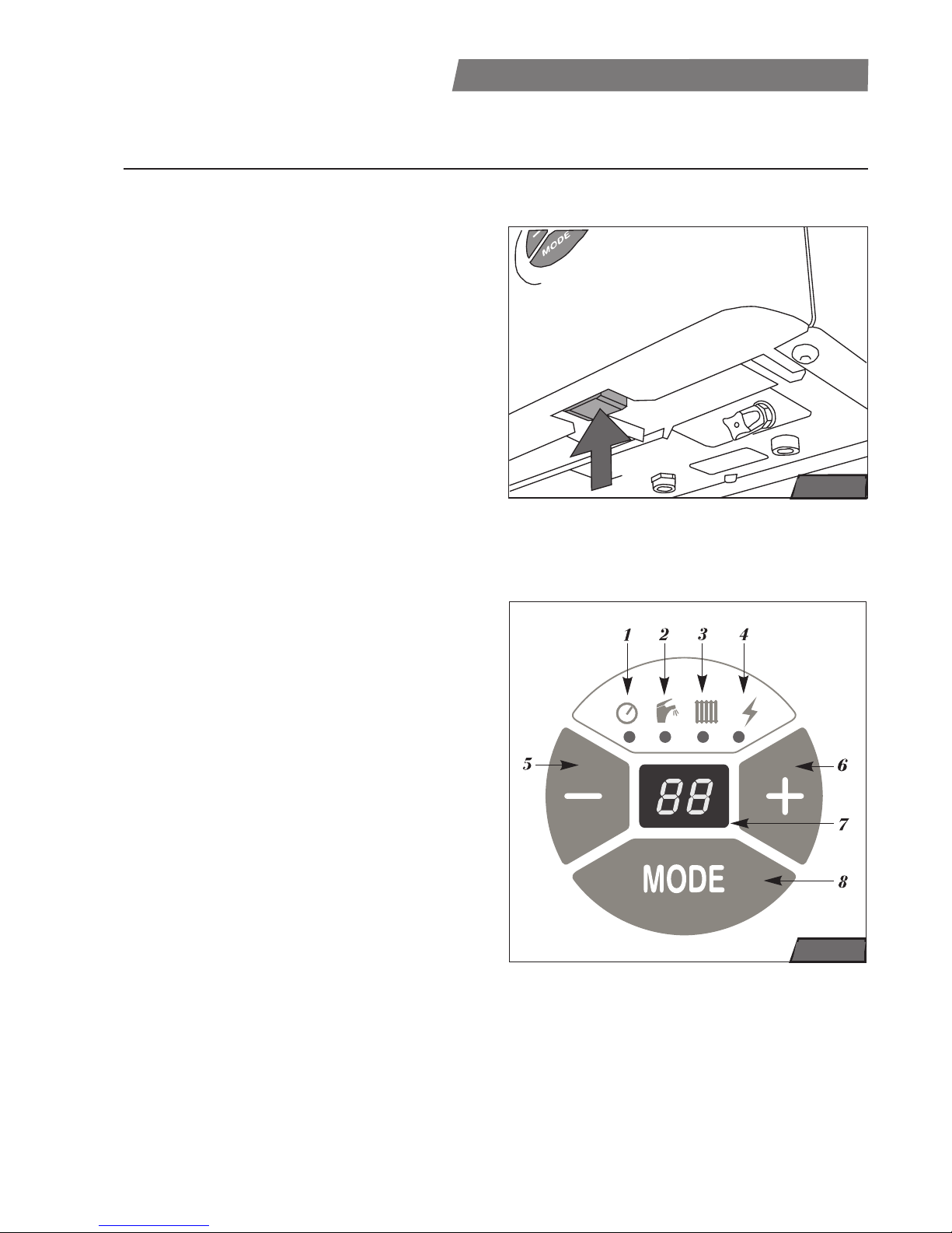
Main on/of switch
The main on/off switch (see fig.1) is on
the bottom of the boiler, below the control
panel.
Caution: Commencing and first start of the
boiler operation may only be carried out by
a specialised service centre! Only turned on
boiler has activated all protective function
(e.g. anti-freeze protection).
Control panel
It serves for indication of actual parameters
and for setting or changing required values
this parameters.
1 - heating system pressure LED
(indication of the heating water
pressure)
2 - domestic hot water LED
(indication DHW taking or domestic hot
water temperature setting)
3 - central heating LED
(indication of the heat requirement or
heating temperature setting
4 - fault message LED
(indication of faults in boiler operation)
5 - decrease button (-)
(decrease the setting value of
parameters)
6 - increasing button (+)
(increase the setting value of
parameters)
7 - display
(showing of pressure, temperatures,
service parameters and fault
messages)
8 - MODE button
(switches between setting modes and
corfirms setting value of parameters)
Control and Signaling
USER INSTRUCTONS
fig. 1
fig. 2
Page 6
5
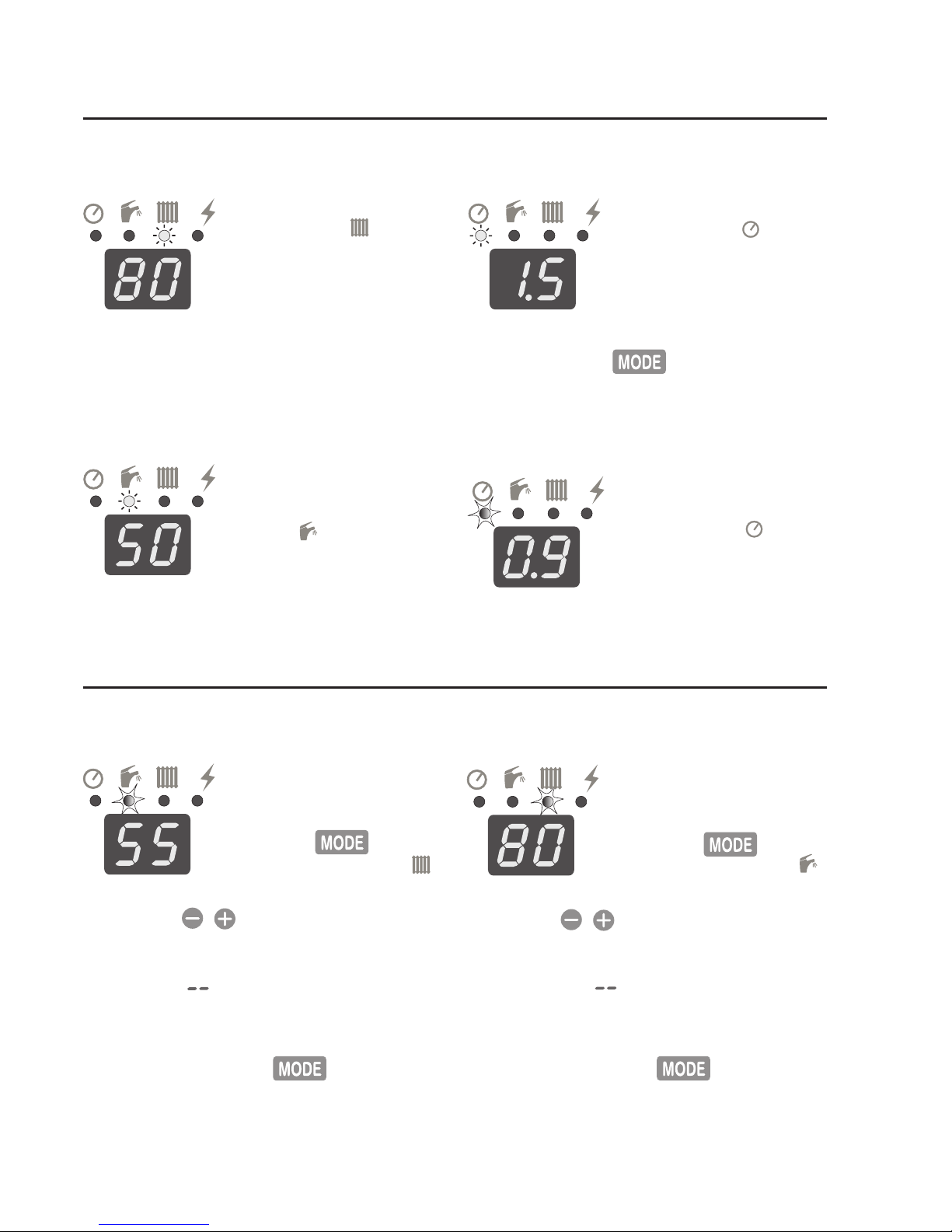
Actual circuit heating water temperature indication in °C.
LED 3 under symbol
lights continuously. The
actual temperature of heating water flowing from
boiler is displayed.
Domestic hot water temperature
indication in °C (required value).
Domestic hot water tap is
open. LED 2 under symbol lights continuously. DHW temperature corresponds with required
value in certain DHW flow
range.
Water pressure in central heating
system in Bar.
LED 1 under symbol
lights continuously. Recommended range is
1 - 2 Bar. Pressure is
displayed for 30 sec.
after one pressing
button.
Domestic hot water temperature
setting in °C.
Temperature is displayed
for 30 second after two
pressing button,
LED 2 under symbol
flash.
Buttons set domestic water temperature to following values: 35, 37, 38,
39, 40, 41, 44, 47, 50, 55, 60°C. Setting
symbol means no preparation domestic hot water.
Setting value are saved into memory
after next pressing button (if it's
not confirmed until 30 sec., the previous
setting is saved again)
Circuit heating water temperature
setting in °C.
Temperature is displayed for 30 sec. after three
pressing button,
LED 3 under symbol
flash.
Buttons set central heating water
temperature to following values: 38, 40,
42, 45, 50, 55, 60, 65, 70, 75, 80°C. Setting symbol switches central heating
off (SUMMER adjustment).
Setting value are saved into memory
after next pressing button (if it's
not confirmed until 30 sec., the previous
setting is saved again).
Boiler indication during ordinary operation (display mode)
Water temperature setting
Warning on wrong pressure in heating system under value 1 Bar (or
over 2,5 Bar).
Boiler still works. LED 1
under symbol flash. It
is necessary to fill up (or
drain) the heating system to pressure 1- 2 Bar
soon.
Page 7

6
Equithermal mode - curve slope
Press the button letter E with the characters
(0) through to (9) attached
will appear on the display.
By pressing the
buttons, select the required
equithermal curve. The cur-
ve´s slope grows with the growing number
(E0 < E9) - see fig. 3.
By pressing the
.button, the selecti-
on is saved in the memory.
Note: Equithermal control requires an external sensor to be connected to the boiler, which must not be set to the SUMMER
mode.
Attention: Boiler does heating with maximal power on one hour after installation of
the outdoor sensor. All settings are ignored in this time except room thermostat (if
is connected).
Equithermal mode – paralel curve
shift
If previous parameter E
was confirmed by pressing the button
- letter P with the characters (0) through to (9)
attached will apear on
display. By pressing the
buttons, select the required shift
(see fig. 3, table 1). For beginning setting
choose the parameter P5, which respond
to outdoor temperature 15 °C (see table
1, fig. 3).
Note: If boiler reaches the reference temperature, then heats system by minimal
temperature (38 °C) till outdoor temperature increase at 3 °C, then is heating
switched-off (see table 1 - switch-off temperature).
fig. 3
Equithermal curves
„P“ parameter 0 1 2 3 4 5 6 7 8 9
Reference temp. °C 6 7 9 11131517192123
Switch-off temp. °C 9 10 12 14 16 18 20 22 24 26
Table 1
Page 8

7
Operation diagram
Page 9

8
No flame - F1
Boiler is switched off, for
example by reason of gas
supply failure. LED 4 under symbol
flash. Boiler can be restarted by
switching off and on (
from
position „I” to position „0“ and again to position „I“
by mains on/off switch). If fault is
frequent, call service centre.
Loss of circuit heating water - F0
Pressure is under 0,7
Bar. Boiler is switched off,
LED 1 and LED 4 under
symbols
and flashes.
After filling system up to 12 Bar the boiler automatically starts. For filling can
be used refilling valve at the bottom of
boiler (see fig. 4). If fault is frequent, call
service centre.
Other boiler faults (from F2 to F8)
Boiler switched off itself.
LED 4 under symbol
flash. It is necessary to
call service centre.
Fault messages
Boiler memory fault - F9
Boiler works, but possibility changes in setting
exists. LED 3 under symbol
lights continuously.
Switch the boiler off and
on (
from position „I” to
position „0“ and again to position „I“
by
mains on/off switch). Then check boiler
parameters (see Water temperature setting). Let check the boiler setting by service centre occasionally.
Note: The preparation for and commencing
of the boiler operation may only be carried
out by a specialised service centre!
Before starting the boiler when it
has been put into operation, check
the following facts:
• The power cord must be plugged into the
socket.
• The gas valve that feeds the boiler must
be open.
• The water pressure in the heating system
should be between 1 and 2 bar
Now the boiler is ready to be started.
Boiler start
Set the mains on/off switch to the “on” position (“I”). Display light up.
Note: In case of safety switch-off due to
extinction of flame or the flue thermostat
reaction (version 24 BOV) LED 4 under
symbol
starts flash.
Boiler can be un-
blocking by switching the boiler off and on
Boiler Start and Switch-Off
(
from position „I” to position „0“ and again
to position „I“
by mains on/off switch).
In case of
safety switch-off due to overheat
thermostat Led 4 under symbol
flash
too, but boiler can be unblocking only by
service centre and this act is not guarantee
repair.
Warning: The boiler must not be operated if the safety elements (e.g. overheat
thermostat, flue termostat) are dis abled or
re placed with elements different from those
specified by the manufacturer.
Boiler switch-off
Set the mains on/off switch to the “off”
position (“0”).
If the boiler is going to be switched off for
a longer time, it is recommended to disconnect boiler from the electricity source
and close gas valve. This must be done
with reference to ambient temperature,
because there is the risk of freezing boiler
and system in frost weather.
Page 10

9
Setting SUMMER mode (only DHW)
• Start the boiler;
• Select “– –” for CH temperature as described under Control and Signalling (CH
temperature setting);
• Activate the basic state by MODE button.
Operation without a room thermostat
Boiler keeps CH temperature on setting
value. The room thermostat is not connected; its contacts must be interconnected
(by utilizing a jumper).
• Set the desired temperature value as described under Control and Signalling (CH
temperature setting);
Operation with a room thermostat
Boiler keeps CH temperature on setting
value, with breaks in operation dependent
upon the temperature in the room in which
the thermostat is installed. The radiator in
that room must not be equipped with a
thermostatic valve head. The settings are
the same as the operation without the room
thermostat, but the jumper is removed and
the room thermostat is connected to the
contacts.
Running the Boiler with Equithermal
Control
The boiler changes heating water (HeW)
temperature according to the changing
outdoor temperature.
Important: The boiler must have an outdoor temperature sensor connected! The
outdoor temperature sensor is installed
on the coldest wall of the building (north of north-west), about 2.5 – 3 m above
ground. The sensor must not be exposed
to any external sources of heat such as
open windows or ventilation shafts or sunshine.
When selecting a heating curve, a rule
applies that curves of a lower number are
suitable for buildings with good thermal
insulation and steeper thermal gradient,
and vice versa.
The heating curve diagram provided is
used as a primary guideline. More accurate setting is achieved by monitoring both
outdoor and indoor temperatures for several days.
In the first setting select the E5 curve.
When doing the setting, all radiator valves
must be completely opened, thermostatic
valves must be set to maximum temperature and doors and windows must be
closed.
Change the curve gradient or reference
temperature in small steps, and after each
new setting wait about 2 hours and then
assess the change. When trying to find
the right setting, it is better to do so when
the outdoor temperature fluctuations are
greater, and the final setting should be
done when the outdoor temperature is below the freezing point.
The boiler is set in the following procedure: 1. Select the “HeW temperature” mode
and make sure that the function “SUMMER” is not activated. (symbol --). Set the
temperature to a concrete value (it will
have no effect on the equithermal mode).
2. Select “Equithermal mode – curve gradient” and set it to symbol E5 – see page
7.
3. Select “Equithermal mode –reference
temperature shift “ and set it to (P5). 4. Put
the boiler into the ready state. After several days of operation (when the premises
have been heated up), change the curve
gradient as necessary.
5. If the indoor temperature does not noticeably change with a changing outdoor
temperature, the selected curve is the correct one. The temperature can be set to
Boiler Regulation
Setting WINTER mode (CH + DHW)
• Start the boiler;
• Select the CH temperature instead of “– –”
as described under Control and Signalling
(CH temperature setting);
• Activate the basic state by MODE button
Page 11

10
Anti-freeze protection of the system
The boiler has build-in protection against
freezing water in boiler (no in whole heating
system or DHW pipes). The boiler is always
started if the CH temperature is below 4°C
and works until CH temperature reaches
8°C. This protection is independent on
room thermostat or SUMMER mode (CH
water temperature setting – – )
Pump protection
The pump is automatically switched on for
a short time (approximately 30 sec.) if it
has not been operated for 24 hours – thus
clogging by sludge sedimentation in the
pump’s bearings is prevented.
Anti-cycling function
This function restrict too repeated starts
of boiler to heating system and it is useful especially in smaller heating system,
when required heating power is smaller
than minimal boiler's thermal power output.
Next start is delayed in range from 1min 30
sec to 5 min.
Overheating protection
If the CH temperature is higher than the
pre-set value of 80°C, the pump is always
switched on and continuously operated. If
temperature further increases, safety thermostat shut boiler down, and thermostat
must be unblocked by service centre.
In case water loss the boiler shut down too,
but it will be reactivated automatically when
the pressure increases again.
Disconnected boiler from el. source
Should the boiler be disconnected from the
electricity source for a long time (continuously for one month or longer), it should be
regularly reconnected and switched on (at
least once a month). If the pump is blocked,
always call a specialised service centre.
Repairs of the pump caused by impurities
in the heating system are not covered by
Protective features of the boiler
a higher or a lower value by shifting the
reference temperature – see the section
“Controls and signals – equithermal mode
– reference temperature shift”.
Please note: If with a decreasing outdoor
temperature the indoor temperature noticeably increases, select a heating curve
of a lower number, and if it decreases,
with a higher number.
Running the Boiler with Equithermal
Control and Room Control Unit
The room control units augments the equithermal control, allowing time setting and
economy heating mode (e.g. at night).
How to set the boiler: • set the equithermal
control as explained above;
• connect the room control unit to the boiler (remove the terminal jumper) and then
set the required temperature during the
comfort period on the control unit to a value about 5°C higher then the temperature
reached with equithermal control. Set the
required temperature during the economy
period (at night, when absent) on the control unit to the actually required value – it
must always be at least 3°C lower than
the actual comfort temperature.
Please note: Room control unit must be
installed by a specialist service organisation.
Example: Select curve E5. With the outdoor temperature -10°C, the boiler supplies water to the heating system of about
70°C. If you at the same time select the
P5 reference temperature shift parameter, when the outdoor temperature rises
by 15°C, the boiler should supply water
to the heating system of 38°C. When the
outdoor temperature rises to 18°C, the
heating water heating is turned off.
Heating power setting
Boiler's power factory setting is 15 kW to
heating system. The maximal power 23 kW
is always available for preparing DHW. Only
service centre authorized by manufacturer
can change heating power in accordance
with requirement of heating system.
Page 12

11
Servicing and maintenance
Refilling water to heating system
Caution: The boiler is installed as part
of a sealed system which must only be
drained and filled by a com pe tent person.
Common user can fill and drain boiler in
order to keep the heating water pressure
in recommended range 1-2 bar.
When refilling, follow these conditions:
• The pressure of the water source must be
higher than that of the water in the heating
system;
•
The temperature in CH has to be lower
than 30°C.
• Recommended water pressure in cold boil-
the boiler’s warranty.
Warning: The protective functions are
only active if the boiler is plugged into the
electrical grid socket and the main switch
is on (in the “I” position).
Stoppage and recovery of electricity
supply
If there is a stoppage in electricity supply,
the boiler is switched off. When the electricity supply is recovered, the boiler will switch
on, without a loss of the parameters.
If the F1 fault message is shown on the
display after the electricity supply recovery,
turn mains on/off switch from position „I” to
position „0“ and again to position „I“ (see
Control and Signalling).
If the boiler does not restart, the overheat
de vice may need resetting by a
specialised
service centre
.
Pump after-running
The pump after-running is standardly set
from factory on 45 sec after shutdown
of boiler by room termostat. If no room
thermostat is used, the pump runs contuniously.
Above-mentioned adjustment can be
changed on the 45 second pump running
after burner stop. This is recommended in
case regulation without room thermostat
Caution: The chages of the pump affter-
running can makes only competent person
autorised by the manufacturer.
Safety valve
The boiler is equipped with a safety valve.
DO NOT TOUCH THE SAFETY VALVE! If
water is leaking from the valve, switch the
boiler off, unplug it and call a specialised
service centre. Only qualified persons
are allowed to fill the boiler with water or
discharge water from the boiler. If there is
a repeated drop of pressure, discuss the
defect with your service centre.
Air flow rate safety device (for version
24BTV with forced flue gas removal)
If an obstruction, even partial, of the flue
occurs, the built in safety sys tem of the
boiler will turn the boiler off. The boiler will
be ready to op er ate when the fault has
been cleared.
Chimney draft control system (for version 24BOV with flue gas removal by
means open chimney draught)
If the chimney draught is impaired or
blocked, gas supply is stopped and the
boiler is automatically shut down and it
will light up fault F1 display on the control
panel. The boiler can be start after cooling
up the flue-gas safety thermostat by turning
the mains on/off switch from position „I” to
position „0“ and again to position „I“.
er (to 30
°C) is in range from 1 to 2 bar.
Note: If the pressure in the water mains
were the same or lower than that in the
heating system, there would be a risk of
heating water entering the water mains,
which must not be allowed. The risk is
lowered by installing a backflow valve on
the water-supply pipe in boiler.
The manufacturer is not liable for any
damages caused by tampering with the
refilling or draining valve or failures to
adhere to the above conditions. No damages or defects so caused are covered
by the boiler’s war ran ty.
Page 13

12
The warranty on boilers is provided as
specified in the Guarantee Certificate,
Service Booklet and under conditions
specified in these Instructions for Use
and Instructions for Installation (in chapters
Introduction, Boiler installation).
Warranty conditions
Too high pressure in central heating system:
If it's necessary to reduce pressure in CH
or drain the boiler, can be used the tap at
the bottom of boiler (see fig. 12 in Installation instruction) Water in CH has to be
cold (max. 30°C), DHW setting and heating
setting have to be ´– –´. Be careful during
draining to prevent damages caused by
water flowing from boiler.
Caution: The frequent water loss indicates
the water escape from system. Too small
pressure in cold system together with too
high pressure in warm system indicates
too much water in system or little air in
expansion vessel. Call service centre
soon.
Cleaning
The boiler can be cleaned with a wet
cloth and then dried and polished with
a dry cloth. Never use any abrasives or
thinners.
Caution: Before cleaning switch the boiler
off by mains on/off switch (to position „0“)
Maintenance and inspections
Checks and maintenance on the boiler
should be regular, at least once a year.
Such inspections are not covered by the
warranty. The Service Booklet contains a
checklist for such inspections, that can
provide only service centre authorised by
manufacturer.
Refilling procedure:
• Check if the power cord is plugged into the
socket and the gas valve that feeds the
boiler is open. The main on/of switch is in
position
„I“.
• Press MODE button to display pressure in
heating system. If the pressure is under 0,7
bar, LED under symbol flash.
• Slowly open the refilling valve and
simultaneously watch the pressure increase
on the display. Pressure is displayed only
30 second after pressing MODE button.
The valve is opened counter-clockwise,
closed clockwise.
• Fill the system to pressure 1 - 2 bar.
• When the desired pressure is achieved,
shut the valve (without applying excessive
force) and check that the water pressure is
not growing (which would occur if the valve
were not closed properly).
fig. 4
Refilling valve
Page 14

13
Category . . . . . . . . . . . . . . . . . . . . . . . . . . . . . . . . . . . . . . . . . . . . . . . . . II
2H3P
Design . . . . . . . . . . . . . . . . . . . . . . . . . . . . . . . . . . . . . . . . . . . . . . . . . . . B
11BS
Ignition . . . . . . . . . . . . . . . . . . . . . . . . . . . . . . . . . . . . . . . . . . . . . . . . . electronic
Gas . . . . . . . . . . . . . . . . . . . . . . . . . . . . . . . . . . . . . . . . . . . . . G20 . . . . . . . . . . . . . G31
Max. thermal power input . . . . . . . . . . . . . . . . . . . . . . . . . . . . 25.5 . . . . . . . . . . . . .25.5
Min thermal power input . . . . . . . . . . . . . . . . . . . . .kW . . . . . 10.0 . . . . . . . . . . . . .10.0
Max. thermal power output . . . . . . . . . . . . . . . . . . .kW . . . . . 23,0 . . . . . . . . . . . . .23.0
Min. thermal power output . . . . . . . . . . . . . . . . . . .kW . . . . . .8.5 . . . . . . . . . . . . . 8.5
Efficiency . . . . . . . . . . . . . . . . . . . . . . . . . . . . . . . . . % . . . . . . . . . . . . . . . 90
Gas consumption (Q max / Q min) . . . . . . . . . . . . . . . . 2,72/1,08 m
3
/h . . . . .2,11/0.89 kg/h
Noise level (1m from boiler, at a height of 1.5 m) .dB(A) . . . . . . . . . . .up to 55
Nox class . . . . . . . . . . . . . . . . . . . . . . . . . . . . . . . . . . . . . . . . . . . . . . . . . . 3
Gas pressure
Input pressure . . . . . . . . . . . . . . . . . . . . . . . . . . . . mbar . . . . . . 20 . . . . . . . . . . . . . . 37
Pressure on burner max/min . . . . . . . . . . . . . . . . . mbar. . . . 12/2,2 . . . . . . . . . . 35,5/6,9
Nozzle diameter. . . . . . . . . . . . . . . . . . . . . . . . . . . mm . . . . . .1,2 . . . . . . . . . . . . . 0,7
Heating
Max. working pressure. . . . . . . . . . . . . . . . . . . . . . .bar . . . . . . . . . . . . . . 3
Min. working pressure . . . . . . . . . . . . . . . . . . . . . . .bar . . . . . . . . . . . . . .0,8
Recommended working pressure . . . . . . . . . . . . . .bar . . . . . . . . . . . . . 1 - 2
Temperature range . . . . . . . . . . . . . . . . . . . . . . . . . °C . . . . . . . . . . . . . 38 – 80
Expansion vessel. . . . . . . . . . . . . . . . . . . . . . . . . . litre . . . . . . . . . . . . . . 5
Max. quantity of water in heating circuit. . . . . . . . . litre . . . . . . . . . . . . . . 70
Max. pressure in expansion vessel . . . . . . . . . . . . .bar . . . . . . . . . . . . . . 3
Domestic hot water (DHW)
Max. input pressure . . . . . . . . . . . . . . . . . . . . . . . . .bar . . . . . . . . . . . . . . 6
Min. input pressure . . . . . . . . . . . . . . . . . . . . . . . . .bar . . . . . . . . . . . . . . 1
Min. water flowrate. . . . . . . . . . . . . . . . . . . . . . litre per min . . . . . . . . . . .2.7
Adjustable temperature range . . . . . . . . . . . . . . . . °C. . . . . . . . . . . . . 35 – 60
Flowrate at 25°C temperature increase . . . . . litre per min . . . . . . . . . . 12.5
30°C temperature increase . . . . . litre per min . . . . . . . . . . 10.8
35°C temperature increase . . . . . litre per min . . . . . . . . . . . 8.8
Electrical data
El. voltage / frequency . . . . . . . . . . . . . . . . . . . . . . V/Hz . . . . . . . . . . . .230 / 50
El. power input . . . . . . . . . . . . . . . . . . . . . . . . . . . . W . . . . . . . . . . . . . . . 95
El. protection class. . . . . . . . . . . . . . . . . . . . . . . . . . IP . . . . . . . . . . . . . . . 45
El. current . . . . . . . . . . . . . . . . . . . . . . . . . . . . . . . . A . . . . . . . . . . . . . . . 0.5
Connections
Heating water in/out. . . . . . . . . . . . . . . . . . . . . . . . . . . . . . . . . . . . . . . . G 3/4"
DHW in/out . . . . . . . . . . . . . . . . . . . . . . . . . . . . . . . . . . . . . . . . . . . . . . G 1/2"
Gas . . . . . . . . . . . . . . . . . . . . . . . . . . . . . . . . . . . . . . . . . . . . . . . . . . . . G 1/2"
Flue
Flue diameter. . . . . . . . . . . . . . . . . . . . . . . . . . . . . mm . . . . . . . . . . . . . 125
Flue gas temperature . . . . . . . . . . . . . . . . . . . . . . . °C . . . . . . . . . . . . . 95-120
Required chimney draft . . . . . . . . . . . . . . . . . . . . . . Pa. . . . . . . . . . . . . . . 2
Weight flowrate – flue gas . . . . . . . . . . . . . . . . . . . .g/s . . . . . . . . . . . . . . 20
Dimensions
Height / Width / Depth . . . . . . . . . . . . . . . . . . . . . . mm . . . . . . . . . 740 /410 / 320
Weight . . . . . . . . . . . . . . . . . . . . . . . . . . . . . . . . . . . kg . . . . . . . . . . . . . . . 33
fig. 6
Technical parameters 24 BOV
Page 15

14
fig. 5
Technical parameters 24 BTV
Category . . . . . . . . . . . . . . . . . . . . . . . . . . . . . . . . . . . . . . . . . . . . . . . . . II
2H3P
Design . . . . . . . . . . . . . . . . . . . . . . . . . . . . . . . . . . . . . . . . . . .C12 , C32, C42, C52, C62, C
82
Ignition . . . . . . . . . . . . . . . . . . . . . . . . . . . . . . . . . . . . . . . . . . . . . . . . . electronic
Gas . . . . . . . . . . . . . . . . . . . . . . . . . . . . . . . . . . . . . . . . . . . . . G20 . . . . . . . . . . . . . G31
Max. thermal power input . . . . . . . . . . . . . . . . . . . . . . . . . . . . 25.0 . . . . . . . . . . . . .25.0
Min thermal power input . . . . . . . . . . . . . . . . . . . . .kW . . . . . 10.5 . . . . . . . . . . . . .10.5
Max. thermal power output . . . . . . . . . . . . . . . . . . .kW . . . . . 23,0 . . . . . . . . . . . . .23.0
Min. thermal power output . . . . . . . . . . . . . . . . . . .kW . . . . . .8.5 . . . . . . . . . . . . . 8.5
Efficiency Qnom . . . . . . . . . . . . . . . . . . . . . . . . . . . % . . . . . . . . . . . . . . . 91
Gas consumption (Q max / Q min) . . . . . . . . . . . . . . . . .2,64/1,1 m3/h . . . . . 2,1/0.89 kg/h
Noise level (1m from boiler, at a height of 1.5 m) .dB(A) . . . . . . . . . . .up to 55
Nox class . . . . . . . . . . . . . . . . . . . . . . . . . . . . . . . . . . . . . . . . . . . . . . . . . . 3
Gas pressure
Input pressure . . . . . . . . . . . . . . . . . . . . . . . . . . . . mbar . . . . . . 20 . . . . . . . . . . . . . . 37
Pressure on burner max/min . . . . . . . . . . . . . . . . . mbar. . . . 12/2,2 . . . . . . . . . . 35,5/6,9
Nozzle diameter. . . . . . . . . . . . . . . . . . . . . . . . . . . mm . . . . . .1,2 . . . . . . . . . . . . . 0,7
Heating
Max. working pressure. . . . . . . . . . . . . . . . . . . . . . .bar . . . . . . . . . . . . . . 3
Min. working pressure . . . . . . . . . . . . . . . . . . . . . . .bar . . . . . . . . . . . . . .0,8
Recommended working pressure . . . . . . . . . . . . . .bar . . . . . . . . . . . . . 1 - 2
Temperature range . . . . . . . . . . . . . . . . . . . . . . . . . °C . . . . . . . . . . . . . 38 – 80
Expansion vessel. . . . . . . . . . . . . . . . . . . . . . . . . . litre . . . . . . . . . . . . . . 5
Max. quantity of water in heating circuit. . . . . . . . . litre . . . . . . . . . . . . . . 70
Max. pressure in expansion vessel . . . . . . . . . . . . .bar . . . . . . . . . . . . . . 3
Domestic hot water (DHW)
Max. input pressure . . . . . . . . . . . . . . . . . . . . . . . . .bar . . . . . . . . . . . . . . 6
Min. input pressure . . . . . . . . . . . . . . . . . . . . . . . . .bar . . . . . . . . . . . . . . 1
Min. water flowrate. . . . . . . . . . . . . . . . . . . . . . litre per min . . . . . . . . . . .2.7
Adjustable temperature range . . . . . . . . . . . . . . . . °C. . . . . . . . . . . . . 35 – 60
Flowrate at 25°C temperature increase . . . . . litre per min . . . . . . . . . . 12.5
30°C temperature increase . . . . . litre per min . . . . . . . . . . 10.8
35°C temperature increase . . . . . litre per min . . . . . . . . . . . 8.8
Electrical data
El. voltage / frequency . . . . . . . . . . . . . . . . . . . . . . V/Hz . . . . . . . . . . . .230 / 50
El. power input . . . . . . . . . . . . . . . . . . . . . . . . . . . . W . . . . . . . . . . . . . . 135
El. protection class. . . . . . . . . . . . . . . . . . . . . . . . . . IP . . . . . . . . . . . . . . . 45
El. current . . . . . . . . . . . . . . . . . . . . . . . . . . . . . . . . A . . . . . . . . . . . . . . . 0.6
Connections
Heating water in/out. . . . . . . . . . . . . . . . . . . . . . . . . . . . . . . . . . . . . . . . G 3/4"
DHW in/out . . . . . . . . . . . . . . . . . . . . . . . . . . . . . . . . . . . . . . . . . . . . . . G 1/2"
Gas . . . . . . . . . . . . . . . . . . . . . . . . . . . . . . . . . . . . . . . . . . . . . . . . . . . . G 1/2"
Flue gas and air ducts
Flue duct / air inlet . . . . . . . . . . . . . . . . . . . . . . . . . mm . . . . . . . . . 100/60 (80/80)
Max length of coaxial ducts 100/60 . . . . . . . . . equivalent m. . . . . . . . . . . 4
Max length of separate ducts 80/80 . . . . . . . .equivalent m. . . . . . . . . . . 10
Flue gas temperature . . . . . . . . . . . . . . . . . . . . . . . °C . . . . . . . . . . . . .115-145
Weight flowrate – flue gas . . . . . . . . . . . . . . . . . . . .g/s . . . . . . . . . . . . . . 18
Dimensions
Height / Width / Depth . . . . . . . . . . . . . . . . . . . . . . mm . . . . . . . . . 740 /410 / 320
Weight . . . . . . . . . . . . . . . . . . . . . . . . . . . . . . . . . . . kg . . . . . . . . . . . . . . . 37
Page 16
15
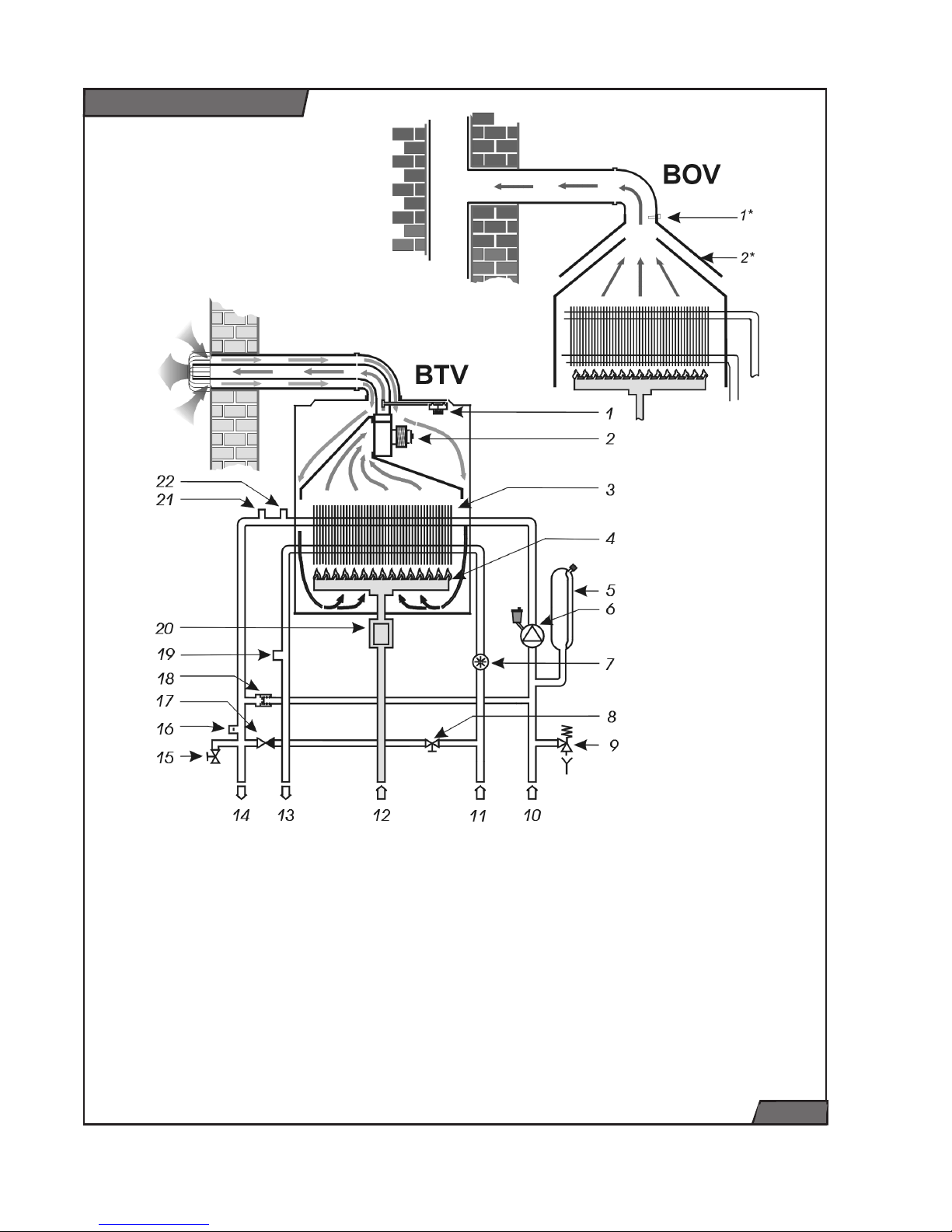
1. manostat
1* chimney draft control system
(flue thermostat)
2. fan
2* draught damper
3. heat exchanger
4. burner
5. expansion vessel
6. pump
7. DHW flow rate sensor
8. water refilling valve
9. safety valve
10. CH inlet
11. DHW inlet
12. gas inlet
13. DHW outlet
14. CH outlet
15. drain valve
16. pressure sensor
17. backflow valve
18. By-pass
19. DHW temperature sensor
20. Gas valve
21. CH temperature sensor
22. overheat thermostat
fig. 7
Boiler schematic
Page 17
16
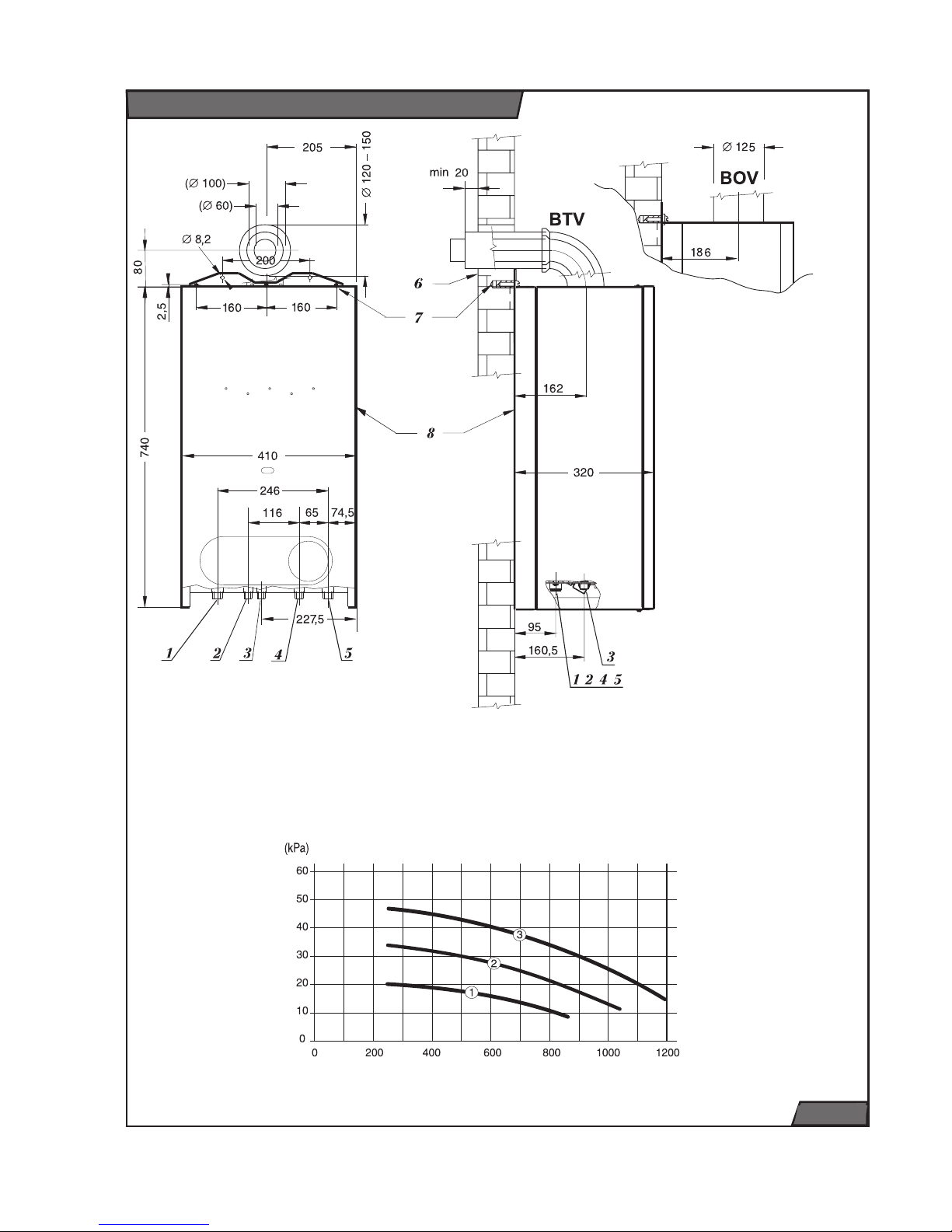
1. CH outlet (outer thread G 3/4")
2. DHW outlet (outer thread G 1/2")
3. Gas in (outer thread G 1/2")
4. DHW inlet (outer thread G 1/2")
5. CH inlet (outer thread G 3/4")
6. Wall
7. Wall-fixing bracket
8. Casing
Dimensions and pressure available
fig. 8
Flow rate through heating system (l/h)
Available pressure (kPa) between
heating supply and return
(10 kPa = 1 m WG)
Page 18

17
24 BTV/BOV is compatible with all
common types of heating water systems
and radiators.
24 BTV/BOV boiler can be put into operation only by an authorised installer in compliance with valid regulations. A network
of the manufacturer’s con trac tu al service
centres provides installation, maintenance
and repairs.
The boiler is designed for operation in a
normal environment (temperatures between +5 and +40°C, humidity up to 85%,
depending on the tem per a ture).
The boiler is suitable for installations in
residential and social rooms as regards
the noise level.
The heating-circuit water must comply
with the relevant Standard (it must not be
acidic, i.e., its pH must be above 7, and
the carbonate hardness must be as low
as possible).
Use of anti-freeze mixtures is not recommended, since they have properties unsuitable for boiler operation. These specifically
include: reduction of heat transmission to
the heating circuit, high thermal expansion of volume, ag ing, de te ri o ra tion of
rubber parts. Even if no other solution for
preventing the system from freezing has
been found, con se quent failures to meet
the operational parameters and/or defects
caused by the use of the anti-freeze mixtures will not be covered by the warranty.
Prior to the final assembly, the heating-circuit pipes should be flushed by pressure
water, several times. For old er cir cuits (that
have already been in use) the flushing
stream direction must be opposite to that
of the heating wa ter.
Installation of a sludge separator is recom-
mended in the incoming branch of heating
water. The design of the sep a ra tor should
enable regular removal of sludge without
necessity to discharge large quantities of
heating wa ter. The sludge separator can
be combined with a filter; however, a filter
itself is not sufficient protection. Both the
filter and the sep a ra tor should be regularly
checked and cleaned.
The relevant standards provide require ments for the water quality: if the sum
of calcium and magnesium concentrations
is above 1.8 mmol/litre, other “non-chem i cal” measures should be taken against
scaling (such as protection by magnetic or
electrostatic field).
The warranty does not cover mechanical
defects caused by foreign bodies and
impurities (e.g., a clogged ex chang er or
pump).
Working temperature of the upper parts
of the boiler (especially the top and side
panels) may be up to 50°C high er than the
ambient temperature. The clearance from
flammable materials (such as chipboard,
polyurethane, polystyrene, polyethylene,
ex pand ed PVC, synthetic fibre, cellulose,
asphalt board, rubber, etc.) must secure
temperature these materials under 80°C.
The minimum handling space around the
boiler should be such that easy and safe
work with bare hands and/or with tools be
possible.
Introduction
INSTALLATION INSTRUCTONS
Page 19

18
For the 24 BTV flue-gas is removed and
combustion air is brought in by a special
double duct. Double-duct routes can be
completed from the standard parts supplied by the manufacturer for virtually any
sit u a tion. The route must be designed to
enable removal of condensed flue vapours
out of the duct. Special con den sate-discharge elements can be used for that
purpose. If any defects are caused by the
condensation, they will not be cov ered by
the warranty. Due to the variability of local
conditions, the double duct elements are
not in clud ed in the de liv ery or in the boiler’s price. Principles for completion of the
routes – see. chapter “Air and flue ducts.”
For the 24 BOV flue-gas is removed by
means open chimney draught. Minimal
required chimney draught in steady stage
is 2 Pa. Connection to the chimney is via
a connecting flue pipe with diameter corresponding to flue outlet on the boiler (125
mm). Installation of both the boiler and the
connecting flue pipes with chimney must
comply with valid standards. The standard's requirements prevent appearance of
adversary effects, such as excessive cooling of the flue gases, penetration of the
chimney wall by humidity, and variability
of chimney draught which would affect the
boiler operation in an undesirable manner.
The connecting flue pipes are not included
in the boiler delivery.
Caution: Elements reducing the chimney
draught (such as various exchangers for
using the residual heat) are prohibited
from being inserted in the connecting
flue pipe.
The 24 BOV takes combustion air from the
space around it. There must be possibility
of direct space ventilation and sufficient
combustion air supplies comply with valid
standards.
Delivery completeness
BTV /BOV boiler is delivered in assembled
state and functionally tested.
Delivery contains (see fig. 9):
1. Boiler
2. User and installation instruction
3. Service book
4. List of Service centres
5. Certificate of Warranty
6. Template
7.
Drawbar for hanging of boiler
Additional accessories
Following accessories can be ordered
according to various requirements;
1. Connecting set, supply number XXXX
(see fig. 10)
2. Flue gas and air ducts 100/60 for BTV
version e.g.:
- S5D-1000 Horizontal set (elbow with flange 90°, 1m horizontal terminal), supply
number 7194
- K1D Elbow 90°, supply number 2842
- T1D-1000 Extension 1m, supply number
2825
- S3 Vertical terminal, supply n. 2805
- Z1 Condensate retainer, supply n. 2857
3. Flue gas and air ducts 80/80 for BTV
version e.g.:
- S2 Air-flue duct set (separator, 2x elbow
90°, 2x 1m horizontal terminal) , supply
n. 2803
- K2A Elbow 90°, supply n.
- T2 Extension 1m, supply n. 2819
- S4 Vertical terminal, supply n. 2809
- Z2 Condensate retainer, suply n. 2858
Page 20

19
Delivery contents
1
Záruční list
Seznam servisních
středisek
Servisní kniha
Návod k obsluze
a instalaci
2
3
4
5
6
7
fig. 9
Connecting set
fig. 10
Connection set contain:
1x assembly platform
2x CH stop valve G 3/4" including gasket
2x Heating system connections - pipe
diameter 22 mm
2x DHW stop valve G 1/2" including
gasket
1x gas stop valve G 1/2" including gasket
1x template
1x drawbar for hanging of boiler
3x bolts including wall plug
Page 21

20
Heating system
Rated diameters of pipes are determined
in the usual manner, depending on the
pump characteristic curve. The piping is
determined by the requirements for the
system in question, not by the boiler’s
maximum power output. Nevertheless, the
piping must provide for a 20°C temperature
difference between the incoming and
outgoing CH and the minimum flow rate
500 litres per hour.
The pipes’ layout must be such that no
bubbles form in the system and purging
is facilitated. Purging valves should be
situated at all high points of the system and
on each radiator. It is absolutely necessary
to flush the system before the new boiler
installation and remove impurities from
heating system.
The heating system’s hydraulic pressure
(measured at the boiler) should be at least
1 bar (corresponding to 10 m of water
column). The recommended pressure
range is from 1 to 2 bar. The expansion
vessel is suitable for max.70 litres of
heating water (for temperature 80°C).
Thermostatic valve heads can be used on
the radiators. If the boiler is controlled by
a room thermostat, the ther mo stat ic valve
heads should not be installed in the room
where the room thermostat is.
The boiler may be connected to the heating
circuit by flexible elements (hoses) during
reconstructions, if necessary because of
the layout, etc. Such hoses must have
parameters suitable for the purpose,
should be as short as possible, protected
from damages caused by mechanical load
and chemical agents, and replacement
must always be arranged prior to the
end of the life-cycle and/or deterioration
of their parameters (according to their
manufacturer’s instructions).
Note: after connecting of boiler to heating
system remove plastic stoppers which are
placed in boiler outlets.
DHW system
The DHW pressure should be between 1
an 6 bars; if it is higher, a reduction valve
must be installed. In areas with very hard
water, suitable measures for softening
should be applied.
It is recommended to install CH, DHW
and gas stop valves on the pipes near
the boiler.
For easy connecting of boiler is used the
special connecting set with stop valves
(see Fig. 10).
Boiler installation
Page 22

21
Boiler hanging
The boiler is hung on the wall on two bolts,
with minimum diameter of 6 mm. Suitable
washers must be placed under the bolt
heads. The connecting fittings have outer
threads. All necessary distances are shown
in the figure of connecting dimensions
(fig.8).
Boiler connecting
It is recommended to install CH, DHW
and gas stop valves on the pipes near
the boiler.
The connection fittings on the boiler
must not be affected by any pressures or
forces from the piping – in other words,
all dimensions and distances of the
connected pipes must be accurate, both
mutually and from the wall and floor. For
this end is supplied special connecting set
(see Fig. 10).
On the hydraulic set at the boiler’s bottom,
the following elements are situated: safety
valve, relief valve and discharge valve.
The boiler should be connected to the
heating system such that it is possible to
discharge water only from the boiler if it is
necessary for repairs.
Boiler hanging
fig. 11
Page 23

22
Boiler filling and draining
Water filling into / draining from the heating
system and the related steps (purging,
setting the expansion vessel) are not
covered by the warranty.
Small quantities of water can be refilled into
the boiler by the refilling valve.
The drain valve is designed to reduce water
pressure in the boiler before repairs. Only
partial discharge of water from the boiler
can be achieved via the drain valve.
Filling/draining valves should be installed at
suitable points of the system for complete
discharge of water from the boiler or the
entire heating system.
Basic conditions and procedure of filling
and draining are described in User
instructions. In additional must be open the
little cap on deaerating valve (on pump),
checked pressure in expansion vessel and
deaerated whole heating system.
Safety valve
On the hydraulic set at the boiler’s bottom
is situated safety valve (see fig. 13), The
safety valve outlet may release hot water
or steam (if the safety pressure limit is exceed ed).
Gas connection
The 24 BTV/BOV - G20 model is designed
for natural gas, with 2.0 kPa rated pressure
in the network and the calorific value of 9
to 10 kWh/m3. The internal gas piping and
the gas meter must be dimensioned for
all gas appliances of the respective user.
The boiler’s connection branch’s rated
inner diameter should be at least DN
1/2", but one degree higher (DN 3/4") is
recommended.
The 24 BTV/BOV - G30 model is designed
for LPG, whose calorific value is between
12.3 and 13.0 kWh per kg. Operation using
portable cylinders would be problematic,
due to both sufficient volume and han dling
of the cylinders; hence a prerequisite for
the operation is installation of an LPG tank
near the heated premises and filling of the
tank by an organisation authorised for such
activities.
Sufficient supply of LPG from the tank to
the boiler (and other gas appliances, if any)
is part of the design and delivery of the
LPG tank . For LPG boilers, a pressurecontrol (reduction) valve should provide the
pressure of exactly 3.7 kPa (37 mbar).
Gas piping in buildings must fulfill the valid
requirements.
Note: for connecting of gas valve must
be always used union nut and gasket
directly placed on gas valve !!!.
Drain valve
Safety valve
fig. 12 fig. 13
Page 24

23
Boiler template
fig. 14
Page 25

24
For 24 BTV, the air input and flue gas
output goes through a special double
duct. The sufficient distance must be
ensured betveen the flue gas duct and
the flammable materials to prevent the
increasing temperature of these materials
over 80°C. Horizontal segments of the duct
are laid with a slope, so that condensate
flows into an opening to the outside (or to
special condensate discharge elements).
it is possible to slightly deviate from the
direction at the elbow-to-straight-piece
connection. Vertical segments of the flue
duct must always be equipped with special
condensate discharge elements.
Maximum length and kinds of flue
design
The maximum length of a concentric and
separate double duct route is in table.
Warning: if the length of the contrentric
double duct is more than 2 Em (separate
ducts more than 4 Em), the flue diffuser
must be taken out of the fan mouth.
Flue gas and air ducts
obr. 15
Em
obr. 16
∅
80
∅
80
L2
L1
Em
obr. 17
obr. 18
flue duct diameter min. length max. length with
diffusor
max. length without diffusor
100 / 60 1,5 Em 2 Em 4 Em
80 / 80 2 Em 6 Em 18 Em
C52 Design
C32 Design
C12 Design
Diffusor
Page 26

25
The most frequent kinds of flue design are
illustrated on fig. 16, 17 and 18. The boiler
24 BTV can be used for next following
designs:
• C42 design - connecting to common
chimney
• C62 design - connecting to separately
approved and sold ducts.
• C82 design - air duct leads combustion air
from outdoor environment and flue gas duct
are connected to chimney.
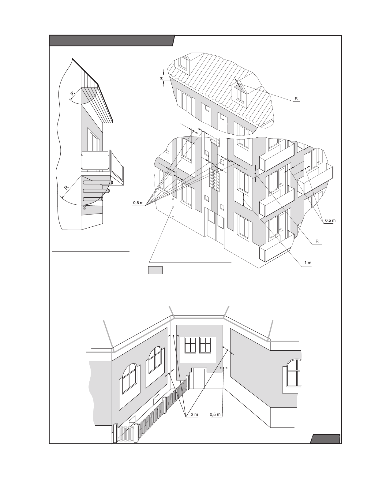
External vent of horizontal ducts on
the façade should be at least:
• 2 m above ground level at publicly
accessible places (0.4 m at other places);
• 0.5 m from sides of windows and other
ventilation openings (grilles) or doors;
• above the top edge of windows, grilles
and doors;
• 1 m below window level, never below
grilles;
• at depth of R (see Fig.19) below
overhanging parts (e.g., roofs, balconies).
Minimum span between external vents:
• 1 m horizontal
• 2 m vertical
The external vent should always be
oriented to the open space (not to doors,
windows or grilles). If this re quire ment
cannot be met, the minimum distances
must be preserved as follows:
a) opposite – between the façade with the
external vent and a façade parallel to it:
• 2 m – if the opposite façade has no windows
or grilles;
• 1 m – if neither façade has any windows
or grilles in it;
• 4 m – if there are windows or grilles (or
external vents) in both façades
b) in corners – between the external vent axis
and the façade parallel to it:
• 2 m – if there are any windows, grilles or
doors in the façade;
• 0.5 m – if there are none.
• Corners smaller than 0.5 m are ignored.
All the distances are understood from the
external vent axis to the outer edge of the
respective window, grille or door.
Special instances
The external vent may also be closer
below an overhanging part, provided it is
equipped with a protruding part of the duct,
whose length at least reaches to the circle
of radius “R” – see. fig 19. .
External vent into a shaft leading to the
open space is possible, if the cross-section
area of the shaft is at least 1.25 m
2
along
its length and there are no doors, windows,
grilles or other flue ducts into the shaft
Vertical external vent – to the roof
Roof vents must be at least 0.4 m from
each other and from air-conditioning
outlets/intakes. Its protruding part must
reach above a snow layer 40 cm thick (if it
were lying on the roof).
Safety precautions
Flue ducts must not be vented into
spaces:
• with a risk of explosion;
• internal (attic, corridor, stairwell, etc.);
• that can be closed, such as passages,
etc.
• below ground level (even if open) such as
tunnels, subways, etc.
If an air intake is separately installed, its
location must be assessed similar to the
above rules.
The opening for the duct passage through
a wall should be bored with sufficient extra
clearance (approx. 120 to 150 mm) and the
duct must be sealed inside of it the sealing
flame proof materials – such as mortar,
gypsum, etc. Passages through walls or
ceilings made of flammable materials must
comply with the valid standard.
Page 27
26
Overhanging parts
Installation in a façade
External vents - Illustration
Corners
fig. 19
2m - in public places
0,4m - in other places
- zone where external vents
can be instaled
Page 28

27
Standard set
Coaxial
elbow 90°
Coaxial duct
Standard set
A Outside casing – air part
B Inside casing – flue gas part
C Collar and clip
D Elbow with flange
E Sealing
F Bolts
G Outer sealing ring (rubber)
I Inner sealing ring (plastic)
J O-ring
• Apply the seal (E) to the bottom part of
the elbow (D);
• Carefully insert the O-rings (J) into the
upper and lower parts inside the elbow;
• Attach the elbow to the boiler – be careful
to con nect the inside part to the boiler’s
outlet properly;
• Put the rubber sealing ring (G) on the air
duct (A);
• Push the completed duct section through
the wall opening so that the (G) ring is
aligned with the outside surface of the
wall;
• Place the collar and clip onto the duct and
elbow; check proper sealing of both inside
and outside sections of the duct;
Note: The maximum horizontal length is 1
elbow plus 3 m (4 equivalent metres) – if
the horizontal route’s equivalent length is
more than 2 m, the diffuser (R) must be
removed from the fan (see Fig. 15 ).
• Secure the elbow’s flange using the
bolts;
Note: If you have to shorten the straight
part, always cut the same length from
both the outside and inside elements.
Always cut at the end opposite to the
external vent.
Example accessories:
Horizontal set 1 m
Horizontal set 0.75 m
Coaxial extension duct (1 m)
Coaxial elbow 90°
Example of horizontal double-duct flue
fig. 20
Horizontal flue - Illustration
Page 29

28
Example of a vertical duct route
• Apply the seal to the coaxial vertical
adaptor (O);
• Carefully insert the O- ring (J) into the
inside part of the vertical adaptor;
• Put the vertical adaptor on the boiler’s and
fan’s outlets;
• Insert the coaxial extension (M) into the
vertical adaptor;
• For passage through the roof cover,
use either special roof tiles (so-called
“ventilation tiles”) or a roof flashing
custom-made by a tinsmith;
• The coaxial extension duct protruding
above the roof should be terminated with
a coaxial (“Meindinger”) head. Instead of
the extension duct and head, a vertical
terminal (L) is better to use as the nicer
top part.
• Attach a condensate-drainage part (tube,
hose, etc. – not included in the delivery)
to the condensate outlet of the vertical
adaptor;
Example accessories:
Coaxial vertical element (O)
Coaxial extension duct (1 m) (M)
Vertical terminal (L)
Example of a vertical double-duct flue
Vertical flue - Illustration
fig. 21
Vertical terminal (L)
Extension duct (M)
Vertical adaptor (O)
Vertical adaptor (O)
Boiler
O-Ring (J)
Groove
Page 30

29
Electrical connection of the boiler to the
power grid is by three-wire cord without
plug. The socket for the plug must comply
with the relevant standard and have the
grounding pin connected to a PE or PEN
cable (yellow-green).
The boiler must be connected to the protective grounding wire; the electrical plug in the
socket must always be accessible without
obstacles. Use of adaptor plugs, extension cords, etc. is prohibited. The boiler
is protected by tube fuse 125 mA/250V
placed on PCB.
Only a person with adequate electricalengineering qualifications can be allowed
to install the socket and the thermostat
(thermostat installation requires utilization
of the boiler’s internal electric cabling); the
same requirements apply to servicing the
electric part. Before any work commences
on the electrical part, the boiler’s cord must
be unplugged.
Only no-voltage thermostats or regulators
can be used for regulating the boiler, i.e.,
they must not bring in any foreign voltage.
The minimum requirements for the regulator’s contacts: 24 V / 0.1 A, A.C.
The room thermostat is connected to the
boiler with a two-wire cable, with copper
wires of a recommended cross-section
between 0.5 and 1.5 mm
2
The connecting cables of the room thermostat should not be led parallel to
other cables or through premises with highpower electric motors (or electric welding
machines., etc.)
The terminal board for connections of the
room thermostat is inside the boiler, on
the bottom. It is accessible after removing
the front cover panel and tilting the control
panel out.
The outdoor temperature sensor is connected to the boiler with a two-core cable
of 0.75 sq.mm cross-section. Maximum
permissible cable resistance may not exceed 10 Ohms, and the total cable length
10 m.
The terminal box for connecting an outdoor sensor and a room control unit is situated next to the terminal box for connecting
a room control unit.
Electrical part
Electrical connection
fig. 22
Page 31
30
24 BTV - Electrical diagram
fig. 23
Page 32

31
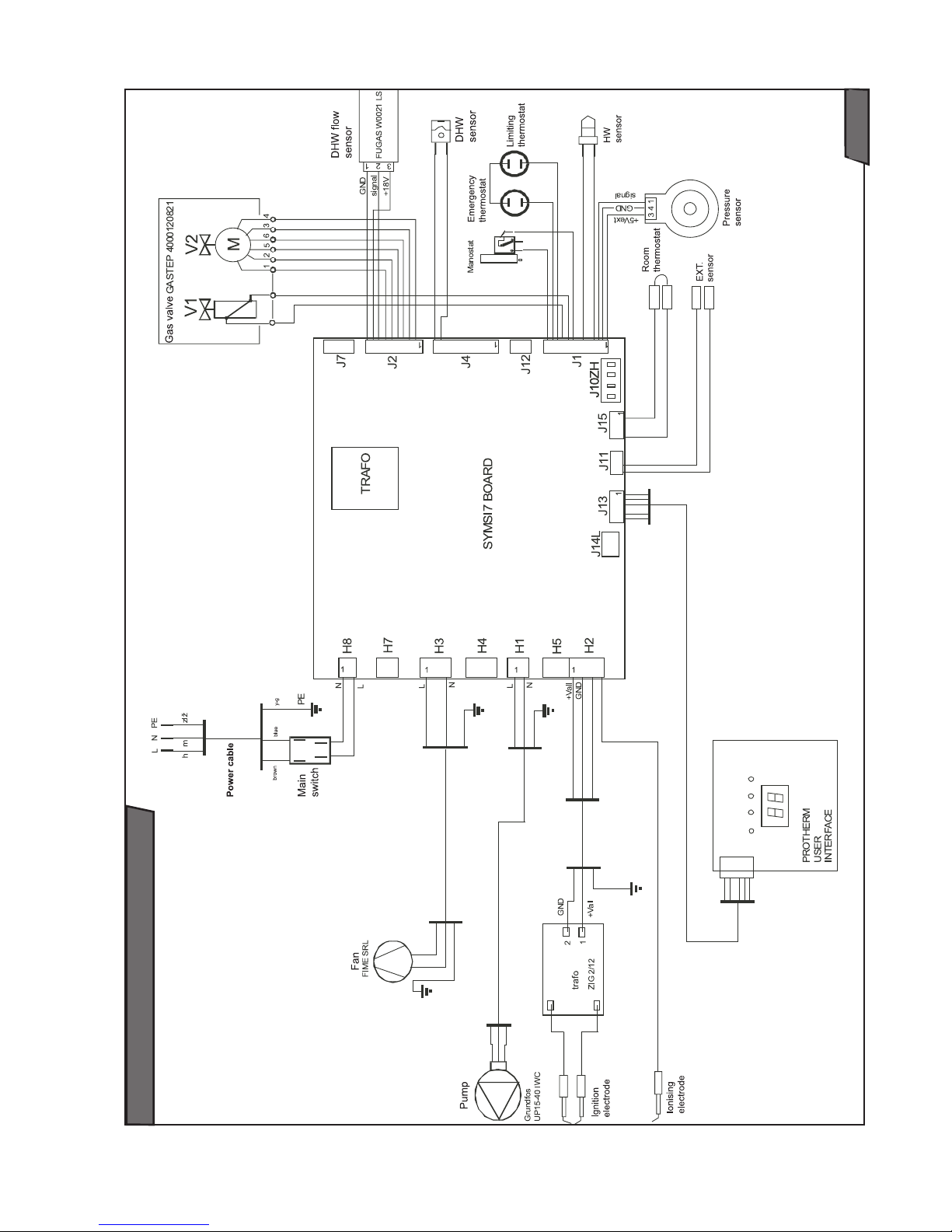
24 BOV - Electrical diagram
fig. 24
Page 33

32
Conversion to LPG
Boiler 24 BTV/BOV is standardly supplied
in the version for the combustion of natural
gas. If the combustion LPG is required, it
is necessary replace gas valve and burner
platform and then set the boiler to specified
parameters. Conversion must only be carried out by a competent person, authorised
by the manufacturer. Gas valve and burner
platform are part of Conversion set. This set
contains all needful parts and Instructions
for conversion.
Page 34

 Loading...