

Page 1
NT-305 數顯式驗電筆操作說明
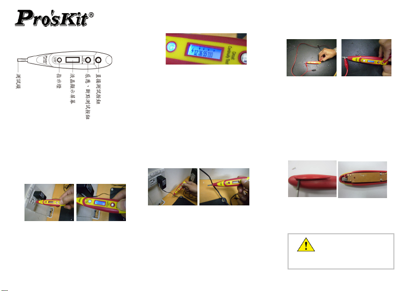
1. 外觀說明:
2. 功能說明:
A. 電壓值測試
AC 電壓測試
『直接測試按鈕』,並將測 接觸 AC 電
源插頭或測試物,此時指示燈會亮起,液
晶顯示屏會顯示測試的電壓值。
DC 電壓測試(12~55V);以手指按壓
接測試按鈕』,並將測試頭接觸 DC 電源或
測試物的正極端,負極端以手拿住或直接
按壓於『直接測試按鈕』(成為一個迴路),
此時指示燈會亮起,液晶顯示屏會顯示測
試的電壓值。
(接觸式):
(110V-220V);以手指按壓
試頭
間。 *顯示為 12,表示電壓介於
*顯示為 12-36,表示電壓介於 12~36V 間。
*顯示為 36-55,表示電壓介於 36~55V 間。
*顯示為 12-36-55-110 ,表示電壓介於
55~110V 間 220V 以下。
『直
*顯示為 220V,表示電壓值於 220V 以上。
B.
線路感應測試 (非接觸式):
以
手指按壓『感應、斷點測試按鈕』,並將測
試 靠
頭 源線,近電 液晶顯示屏的左側若顯示閃
電符號,表示此線路正常通電;
符號,表示此線路不帶電源。
C. 線材導通測試:
將線材的一端與測試頭接觸,線材另外一
端與直接測試按鈕接觸,進行導通測試。
9~12V
若未出現閃電
指示燈亮起,表示線材導通,指示燈不亮,則
表示線材有斷點。
D. 驗電筆自我檢測:
以雙手同時按壓『直接測試按鈕』及測試
頭,指示燈亮起代表驗電筆功能正常。
以同樣上述方法,您可以輕易的檢查家庭
的燈泡、保險絲、家電的電源線..等家電用
品電源線路的通斷線情況.
3. 電池更換:
1. 產品背面,使用一字起子將筆夾撬起
2. 鬆開背蓋上二顆螺絲,打開背蓋
3. 更換電池後,將背蓋蓋回鎖上螺絲並裝回
筆夾。
操作前,請先測試已知的線
路,若無法測試時,請更換電
池,若仍無法測試,請洽您的經銷商
Page 2
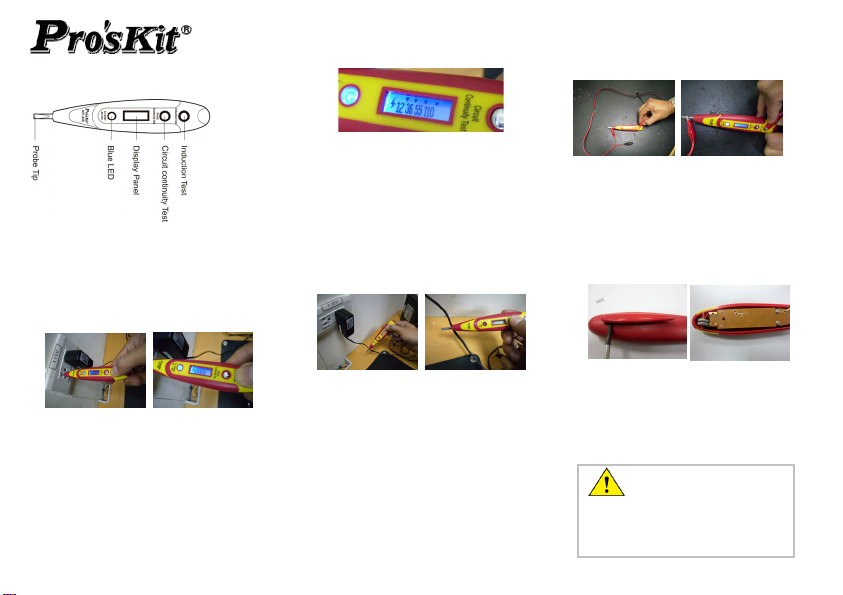
1. Appearance
NT-305 Contact Voltage Tester Operation Guide
2. Operation
1. Voltage Test ( contact) :
AC voltage test: press the” induction test”
button and place probe tip in contact with plug,
circuit or unit to be tested, The LED lights up
and displays voltage values.
DC Voltage Test: press the” induction test”
button and place probe tip to contact with plug
or the anode side of obj ect, the other hand
holds the cathode side of obje ct or press the
cathode side of object in touch with the
“induction test” button to cause a circuit to be
tested. The LED lights up and d isplay comes out
with voltage values.
*If display 12 means the voltage is 9~12V.
*If display 12 36 means the voltage i s 12~ 36V.
*If display 12 36 55 means the voltage is 36~55V.
*If display 12 36 55 110 means the voltage is
55~110V and under 220V.
*If display 220 means the voltage is above 220V.
2. Cable Detection Test (non-contact )
Press the “circuit continuity test” button and
place the probe tip near to the wires or circuit to
be tested.
If the “flash” signal is shown on the display
panel, means it is live wire. If not, the wire is not
live.
3. Circuit Continuity Test:
Set one end of the wire to contact the probe tip
and the other end of wire in touch with
“induction test” button as following pictures.
If the LED lights up, it means the wire is in the
circuit, if not, the wire is open.
4. Tester Function Test
Press the” induction test” button with your hand
and touch the probe tip with another hand, if the
LED lights up, it means it is functioning.
5. B
attery Replacement:
1. Remove the pen clip on the back side of the
ster
te
2
. Loosen 2pcs screws on the cover
3. Remove the back cover, and replace the
batteries. Please pay attention with the
polarity when replace it.
4. Put the cover back, tighten the screws and
put the pen clip back as well
Before operating, please test
the unit on a known live
circuit, if the unit does not function as
expected on a known live ci rcuit, replace
the batteries, if the unit still does not
work, please contact your distributor.
 Loading...