


MT-1217
3-3/4 Autorange Digital Multimeter
User’s Manual
1st Edition, 2013
©2013 Copyright by Prokit’s Industries Co., Ltd.
Contents |
|
General------------------------------------------------------------------------- |
1 |
Open-Package Inspection------------------------------------------------- |
2 |
Safety Note ------------------------------------------------------------------- |
2 |
Instrument Panel& Button Function Description---------------------- |
5 |
Other Functions--------------------------------------------------------------- |
6 |
Property------------------------------------------------------------------------- |
6 |
Instrument Maintenance--------------------------------------------------- |
16 |
Fault Elimination------------------------------------------------------------- |
17 |
General
This product is equipped with the LCD display of text height 20mm, is a 3 3/4 digital multimeter which has the merits of clear reading, stable performance and high reliability. It can be used to measure DC voltage, AC voltage, DC current, AC current, resistance, capacity, frequency/duty cycle, diode and make on-and-off test. Meanwhile, it is available for unit symbol display, automatic/manual range switching, automatic power off and alarm function. The multimeter has high resolution and precision, due to its complete functions, high measurement accuracy and convenient operation, ideal for general electrical testing and troubleshooting
1
Open-package Inspection
Open the package box and take out the meter, check carefully if the following accessories are absent or damaged. If there is any absence or damage, please contact the distributor immediately.
Digital multimeter |
1 PC |
User’s manual |
1 copy |
Test leads |
1 pair |
Temperature Probe (K-Thermocouple) |
1 PC |
Test socket |
1 pc |
Safety Note
The design of this meter is accordance with IEC1010 clause (the safety standard issued by International Electro technical Commission). Prior to the operation of the instrument, please read the safety considerations before use.
1.When DC voltage above 30V, AC voltage above 25V, current above 10mA, AC power line with inductive load or power line during electric fluctuation is measured, please beware of electric shock.
2.Prior to measurement, check if the measurement function switch is at the correct position. Check if the test lead is contacted reliably, connected correctly, and grounded well and etc. in order to avoid electric shock.
3.Only if the meter is used with the matched test lead, will it can of the test lead is damaged, it is necessary to replace with another one of the same model or the same electrical specification.
4.Don’t use other unconfirmed or disapproved fuse to replace the fuse inside the meter. Only the same model or same specification fuse can be replaced. Before the replacement, the test leads must be removed from the measuring point to ensure there is no longer any signal at the input terminal.
2
5.Don’t use other unconfirmed or disapproved battery to replace the battery inside the meter. Only the same model or same electrical specification battery can be replaced. Before the replacement, the test lead must be removed from the measuring point to ensure there is no longer any signal at the input terminal.
6.When the electrical measurement is made, never let your body get in touch with the ground directly, and don’t touch uncovered metal terminal, output port, lead clamp and etc. where earth potential may exist. Dry clothes, rubber shoes, rubber cushion and other insulating material are usually used to keep your body insulated against the ground.
7.Don’t store and use it in the high-temperature, high-humidity, inflammable and strong magnetic field environment.
8.It may damage to the meter and endanger the operator’s safety if the voltage value beyond the permitted ultimate voltage value is measured. The ultimate voltage value permitted for measurement is marked on the instrument panel, and never measure the value exceeding the standard. Don’t input the ultimate value out of regulation in order to avoid electric shock and the damage to the meter.
9.When the test lead is inserted into the current socket, don’t measure any voltage for fear that the meter should be damaged and the operator’s safety be endangered.
10.Don’t try calibrating or repairing the meter. When necessary, only the qualified professional personnel who have had special training or gained approval can make it.
11.During measurement, the requirement of measurement function must be in accordance with LCD display. Please be sure to disconnect the line of the test lead with the measured object first and ensure there is no any input signal. It is forbidden to switch the function/range selection switch during measurement
3
12.When “ ” is shown on LCD display, please replace battery immediately to ensure the measurement precision.
13.It is not allowed to insert the test lead into the current terminal to measure voltage!
14.Please don’t change the circuits of the meter freely for fear that the meter is damaged and the safety be endangered.
15.Description of Safety Symbols
|
Warming! |
|
DCV |
|
|
|
|
|
Double |
|
ACV |
|
Insulation |
|
|
|
|
|
|
|
Fuse |
|
DCA |
|
|
ACA |
|
|
|||
|
|
|
|
|
|
|
In accordance with the |
|
Low |
|
|
|
|
instruction of European |
|
|
Battery |
|
|
|
|
Trade Union |
|
|
|
|
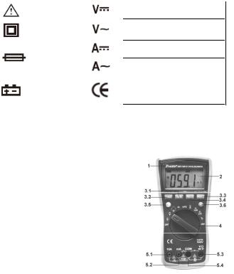
Instrument Panel & Function Button Description
1.Instrument model number
2.LCD Display: Display the measured data and unit.
3.Function Button
3.1Hz/% (Frequency / Duty
Cycle): Press this button to select the frequency or duty cycle mode. The measurement mode of Voltage / frequency / duty cycle could be selected by pressing this button in AC voltage setting
3.2 RANGE: Press this button to select the voltage/current test range
4
3.3HOLD: date hold
3.4REL (Relative Value Measurement): The relative value measurement of Capacity function could be conducted by pressing this button
3.5Select(Function Switch): Press this button, the function could switch between resistance, capacity and  AC/DC current
3.6LCD backlight button
4.Knob Switch: It could be used to change the measurement function and range.
5.Input Terminals
5.1.10A “+”input terminal.
5.2.mA “+” input, Temperature “+” Input, Capacity and HFE input terminal
5.3.Voltage, Diode, Resistance, Frequency, Buzzer Input terminal
5.4.COM: Current, Voltage, Diode, Resistance, Capacity, Frequency, Buzzer, Temperature “-”, HFE, Input terminal.
Other Functions Auto Power off
During measurement, the meter will automatically shut down (enter sleeping mode) to save power if function buttons and knob switch are not operated in 15 minutes. In auto power off mode, press any function buttons or rotate the knob switch, the instrument will get into the auto power on mode (working mode)
Property General Feature
1-1 Display: LCD
1-2 Max Display: 3999(3 3/4) counts automatic polarity display and unit display
5

1-3 Measuring Method: Dual integral A/D converter 1-4 Sampling Rage: Approx. 3 times / sec.
1-5 Over Range Indication: Display “OL”
1-6 |
Low Battery Indication: “ |
” symbol appears; |
1-7 |
Operation Environment: (0~40)˚C Relative Humidity:<80% |
|
1-8 |
Storage Environment: (0~50)˚C Relative Humidity:<80% |
|
1-9 |
Power: a 9V battery (NEDA1604/6F22 or equivalent) |
|
1-10Dimension (size): 182×90×46mm
1-11 Weight: Approx. 320g (not including 9V battery)
1-12 Accessories: User’s Manual (1 pc), color box (1 pc), 10A test leads (1 pair), K-Thermocouple(1 pc) , test socket (1 pc).
Technical Feature
2-1. Accuracy: ± (a% × reading + digits),at (23±5)˚C, relative Humidity <75%. One year calibration guarantee since the time dispatched from the factory.
2-2. Technical Specification
2-2-1. DCV
A)Turn the knob switch to “ “ Range
B)The initiate state of the meter is in automatic range status, which shows “AUTO” symbol
C)Make the test lead contacted to the testing point. The voltage and polarity of the point where the red pen is contacted will be displayed on the screen.
 Caution:
1.Don’t measure voltage over 1000V. Otherwise, there is a danger of meter being damaged.
2.When measuring high voltage, special attention should be given to personal safety and avoid your body getting in touch with high voltage circuit.
6

Range |
Accuracy |
Resolution |
400mV |
±(0.5%+4d) |
100uV |
4V |
|
1mV |
40V |
|
10mV |
400V |
|
100mV |
1000V |
±(1.0%+6d) |
1V |
Input Impedance: 10MΩ .
Overload Protection: 1000V DC or AC peak value
2-2-2. ACV
A)Insert black test lead into the hole of “COM” and red test lead into “ “
“
B)Rotate function switch to “  “ setting , the initial state of the meter is in automatic range status, which shows “AUTO” symbol
C)press “Range” button can select the AC measurement range
D)Make the test lead contacted to the testing point. The voltage of the point where the red test lead is contacted will be displayed on the screen.
 Caution:
1.Don’t measure voltages over 750V, otherwise, the meter will be damaged.
2.When measuring high voltage, special attention should be given to personal safety and avoid your body getting in touch with high voltage circuit.
Range |
Accuracy |
Resolution |
4V |
±(0.8%+10d) |
1mV |
40V |
|
10mV |
400V |
|
100mV |
750V |
±(1.0%+10d) |
1V |
7

Input Impedance: 10MΩ .
Overload Protection: 1000V DC or 750 AC peak value.
Frequency Response: (50~200) Hz
Display: Average value response (RMS of sine wave).
2-2-3. DCA
A)Insert the black test lead into the “COM” input terminal and red test lead into the “mA “ input terminal. (Max 400mA), or “10A “input terminal (Max 10A).
B)Rotate function switch to Current setting. The initial state of the meter is in automatic range status, which shows “DC” symbol. Then connect the test lead to the tested circuit in serial, the tested current value and the current polarity of the point where the red pen is contacted will be displayed on the screen simultaneously.
 Caution:
1.If “OL” is displayed on LCD, it indicates the tested current value has exceeded the present range limit, please select higher range to complete the measurement.
2.The Max input value is 400mA or 10A. (Depending on the terminal where the red test lead is contacted)
Range |
Accuracy |
Resolution |
400uA |
±(1.0%+10d) |
0.1uA |
4000uA |
|
1uA |
40 mA |
|
10uA |
400mA |
±(1.2%+10d) |
100uA |
4A |
10mA |
|
10A |
±(1.2%+10d) |
10mA |
Max measurement voltage drop: Full Range mA is 0.4V, A is 100mV;
Max input current: 10A (less than 15 seconds);
Overload Protection: 0.4A/250V resettable fuse, 10A/250V fuse.
8
 Loading...