

Page 1
Telecom Test Set
U s e r ’ s M a n u a l
Page 2

Thanks for purchase MT-8002 Test set. Before using MT-8002 test
set, please read this page and the Safety Information carefully.
No part of this publication may be reproduced, stored on a retrieval system, or
transmitted, in any form or by any means electronic, mechanical, photocopying,
recording, or otherwise, without the prior written permission of Industries. The use of trademarks or other designations is for reference purposes only.
NOTICE
Industries makes no warranties about this document. Industries reserves the right to make hardware and software changes to the
product described within this document without prior notice and without obligation
to notify any person of such revision or change.
TRADEMARKS
is a registered trademark of Pro’sKit Industries.
REGULATORY INFORMATION
WARNING:
This equipment generates, uses, and can radiate radio frequency energy,
and, if not installed and used in accordance with the installation manual,
may cause interference to radio communications. It has been tested and
found to comply with the limits for a Class A digital device pursuant to
Part 15, Subpart J of the FCC rules, which are designed to provide reasonable protection against such interference when operated in a commercial
environment. Operation of the equipment in a residential area is likely
to cause interference, in which case the user, at his own expense, will be
required to take whatever measures may be required to correct the interference.
2
Page 3
Safety Information
Read First Before Use
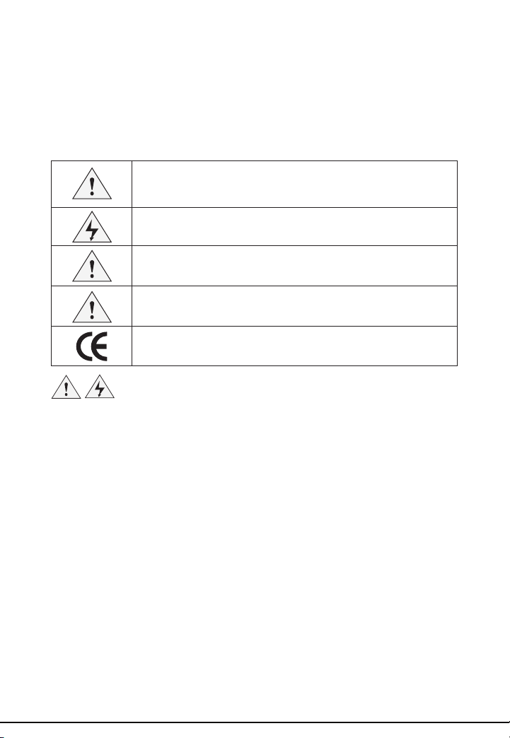
Table 1 describes the international electrical symbols used on the tester and in
this manual.
Warning
Warning: Risk of personal injury. See explanations in the manual.
Caution: Risk of damage or destruction to equipment or software. See
explanations in the manual.
Warning: Risk of electric shock.
Please keep eye on the status or function of the equipment while
operating.
See Manual for details
Conformité Européénne
• Never use MT-8002 on circuits of more than 125V.
• Never use MT-8002 or test leads if they are damaged. Inspect the cases
and test leads for damage before use.
• Disconnect unused test leads and connectors from the MT-8002 when
testing telephone circuits.
• Never open the case except to change the battery or the fuse; no
user-serviceable parts are inside.
• Disconnect all test leads before replacing the battery.
• Use only 1.5V batteries, properly installed in the case, to power MT-8002.
• If this equipment is used in a manner not specied by the manufacturer,
the protection provided by the equipment may be impaired.
Table 1. International Electrical Symbols
3
Page 4

MT-8002 Telecom Test Set
This MT-8002 package includes
Standard package:
• MT-8002 x 1
• Headphone x 1
• Neck Strap x 1
• Standard alligator clip x 1
• RJ-45 to RJ-45 change cord x 1
• RJ-45 to RJ-11 change cord x 1
• User Guide x 1
DESCRIPTION
MT-8002 is a portable Telecom test set used by installers, repair technicians and
other authorized personnel for temporary communication and for servicing and
installing analog voice telephone and with ADSL lines.
Design Features
The MT-8002 provides a wide range of features for working on analog voice
lines, and, in addition, it is equipped with protection features to prevent the accidental disruption of data services. Never use MT-8002 on circuits of more than
125V.
The following is a list of the MT-8002 features:
• LCD display for dialing number, Caller ID, Clock and other information
• Indicator for determine the Net service and speed
• Headset & Neck strap provide convenience hand-free function
• Smart power saving function. Estimate battery life up to 6 months
• 62 Caller ID memories-each memory up to 12 digitals
• 16 Last Number Redial-each number up to 12 digitals
• Support 2 dialing mode: Tone (DTMF) and pulse
• Up to 16 digitals phone number speed store key
• Pre-dialing and last number redial function
• PBX pause key, insert a PBX pause in stored numbers
• Cable continuity & Tel. line polarity indicators
• RJ-45 port for extension change cord
• Standard alligator clip
4
Page 5

WARNING:
• The MT-8002 Telecom Test Set is not designed to meet the outside plant
requirements. It is recommended that this product not be used outside
during adverse and/or wet weather conditions.
• Legal requirements may exist regarding permission to connect equipment
to a Telecom network operated by a public network operator.
CAUTION:
The operator of this instrument is advised that if the equipment is used
in a manner not specied in this manual, the protection provided by the
equipment may be impaired.
5
Page 6
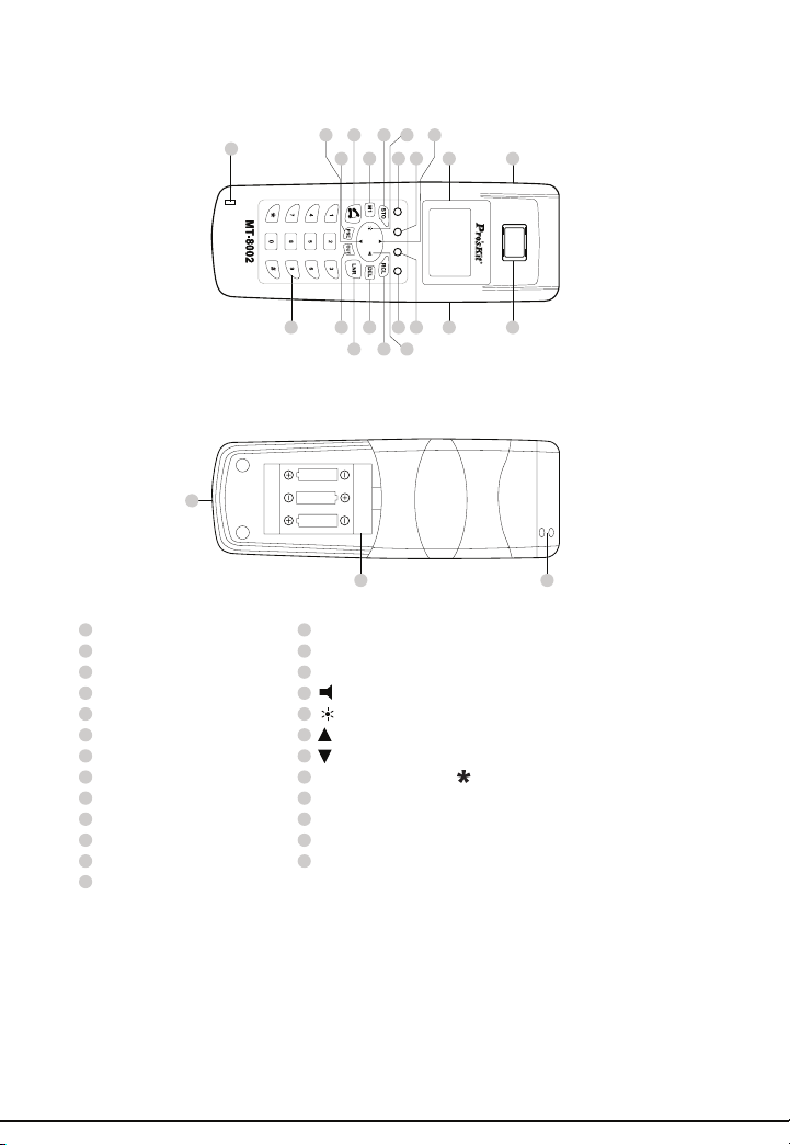
Physical Characteristics
25
1120
18 19
1
345678101513
1221
17
16914
AAA
24
1
Headset Jack LNR (Last Number Redial)
2
Speaker DEL (Delete)
3
LCD Display RCL (Recall)
4
Test mode switch Volume adj.
5
ADSL indicator Brightness adj.
6
CABLE indicator Up
7
TEL + indicator Down
8
TEL – indicator Number pad 0~9, , #
9
STO (Store) Strap hole
10
M1 (Memory 1) T-P Switch (Tone/Pulse Switch)
11
On/Off hook RJ-45 Jack
12
OUT Microphone
13
PSE (Pause) Figure 1
AAA
AAA
14
15
16
17
18
19
20
21
22
23
24
25
2
2223
Test mode switch
The Test mode switch is a slide switch located on the right side of MT-8002 (see
Figure 1). Switching the Test mode switch to the TEL position make the test
set acts as a telephone line tester. Switching the Test mode switch to the ADSL
position make the test set acts as a LAN signal detector. Switching the Test mode
switch to the CABLE position will let the test set acts as a CABLE tester.
6
Page 7
Hand-free function
The MT-8002 Telecom Test Set comes with a headset and a neck strap. Connect
them to the headset jack and strap hole will give the MT-8002 a hand-free talk
function. Please nd the strap hole and the 2.5 mm jack on the left upper core of
MT-8002 Telecom Test Set.
For information on availability of additional headsets and neck strap or replacement headsets and neck strap, contact your local Por’sKit authorized distributor.
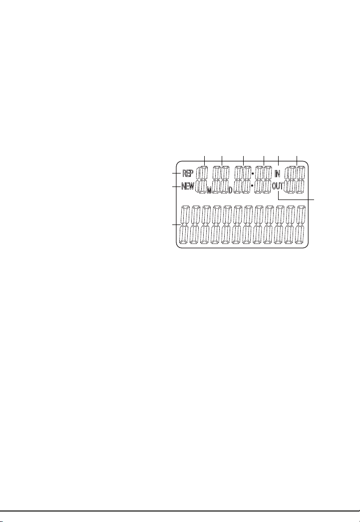
Display
LCD Display
1. Year / Phone number
2. New call number
3. Repeat call number
4. Month
5. Date
6. Hour
7. Minute
8. Incoming call indicator
9. Sequence of the call in list
10. Dialing call indicator
LED Dsiplay
• TEL-/ TEL+ : (Only working on TEL mode)
• TEL+ on : The red clip of alligator clip is connect to the + line
• TEL- on : The red clip of alligator clip is connect to the - line
• ADSL : (Only working on ADSL mode)
• Flash : the LAN signal of ADSL line is 100 MB/s
• Always on : the LAN signal of ADSL line is 10 MB/s
• CABLE :
• TEL mode :
• On : MT-8002 test set is Off-hook
• Off : MT-8002 test set is On-hook.
• CABLE mode:
• On : the tested line has continuity
• Off : the tested line has a break or disconnected
3
2
1
4 5 6 7 8 9
10
T/P Switch
Use T/P switch to change the dialing mode between tone(DTMF) and pulse mode
7
Page 8
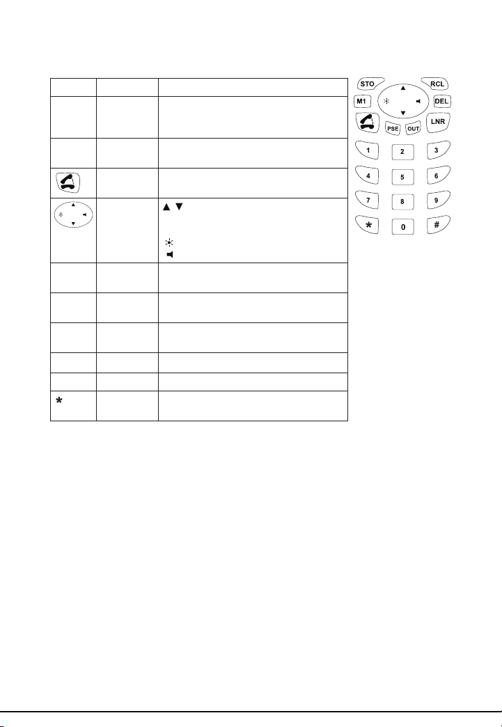
Keys
Key Description Function
STO Set and
M1 Speed
RCL Recall To initial a phone call from stored phone
DEL Delete Delete the number in list or erase the last
LNR Last num-
PSE Pause Insert a PBX pause into the input number
OUT Call out list Enter the dialing out number list
, #,
0~9
Storage
memory 1
On/off
Hook
4 directions
key
ber redial
Number
keys
Press STO key will enter the setting
mode, there are 6 setting screen on MT-
8002. Please refer to Operation section.
Provide a 16 digits number storage
space
On/Off Hook MT-8002 test set
/ : enter the incoming call list, scroll
the numbers in call list and switch the
setting screen.
: LCD brightness level sesect
: Volume select
number
digit from the input number
Make a phone call for last dialing number
or per-dial number
Standard Phone number keys
Line Cord and RJ-45 Jack
The MT-8002 Telecom test set is equipped with a standard alligator clip cord,
a RJ-45 to RJ-45 change cord and a RJ-45 to RJ-11 change cord. To use the
cords please nd the RJ-45 jack near the button of the MT-8002 Telecom test set.
The RJ-45 jack is also compatible with RJ-11 plug.
8
Page 9
Battery
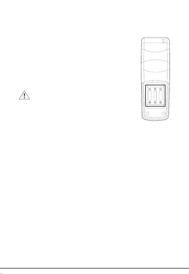
MT-8002 Telecom test set use 3 x 1.5V AAA batteries as power source. (Which
are not include in this package) The estimate batteries life is about 6 months.
To replace the batteries (see Figure):
1. Disconnect all the test probe.
2. Place the test set on a work surface, face down. The work
surface should be nonabrasive.
3. Remove the battery door cover and the old batteries from
the test set. Properly discard the battery.
4. Insert 3 new 1.5 Volt AAA size batteries. Make sure the polarity
is correct.
5. Replace the test set’s battery door cover on the test set.
AAA
AAA
AAA
Note: If the test set fails to operate properly at any time,
rst replace the battery and retest before sending the test
set in for repair.
If the MT-8002 stops working, replace the batteries rst. If it still doesn’t work,
contact Pro’sKit authorized distributor.
9
Page 10

OPERATION
MT-8002 Telecom test set has three modes of operation: TEL mode, ADSL mode
and CBALE mode. Before introduce operations of the three mode, we should
know more about the parameter setting.
Parameter Setting
With MT-8002 on hook, press STO key will enter the setting mode. The “SET 1
DATE” shows on LCD. User can switch the setting item by press / key then
press STO key to enter the setting. If user wants change the setting press the
/ key again. When the correct setting is appears, press STO key to move to
next setting. During the setting press DEL will quit from the setting mode.
• Date and time
If the “SET 1 DATE” display on LCD, press STO key to enter the Date and Time
setting. The number of year will ash, press / key to adjust the value of
year. Press STO key again will move to the month setting. Use the same way
to change the value of month then press STO to move to the date and time
setting. When all the value of date and time are correct, press STO key to move
to “SET 2 ACODE”.
• Area code
When the “SET 2 ACODE” is displayed on LCD, press STO key to enter the
area code setting item. LCD will show “ACODE-----“. The rst digit of area code
will ash, press / key to change the value. Press STO key to move to the
nest digit. If all the digits are set, press STO key to enter “SET 3 FLASH”.
• Pause Duration
If the “SET 3 FLASH” is displayed on LCD, press STO key to enter the Pause
Duration setting. LCD will show “FLASH 1 600”. It means the default pause duration time is 600 ms, Change the value by / keys then press STO to move
to the “SET 4 LCD”.
• LCD light adjust
When the “SET 4 LCD” is displayed on LCD, press STO key to enter the LCD
brightness adjust mode. There are 5 LCD brightness level can be selected.
Press / key to change the level then press STO to jump to “SET 5 ALAR” or
press DEL to quit.
10
CAUTION:
The “SET 5 ALAR” is not used by MT-8002, we suggest users do not to
change the value in “SET 5 ALAR” setting. In this setting item press STO
to jump to “SET 6 IPP” or press DEL to quit.
• Dialing mode
If the “SET 6 IPP” is displayed on LCD, press STO key to enter the dial mode
setting. The IPP ON/OFF will show on LCD, use / key to swap between
them. If “IPP OFF” is selected, the dialing mode is tone. Otherwise, the dialing
mode is pulse.
Page 11

TEL Mode
The MT-8002 can be used as a telephone when it is switched to TEL mode and
is connected to a working analog Tel. line. The MT-8002 works like a normal telephone. When off-hook, the MT-8002 is used to perform its main purpose, which is
to test the proper operation of analog voice telephone lines.
• On-hook
• Pick up call
When receiving a FSK or DTMF call, the Caller ID and the calling time will
display on LCD. The MT-8002 will also add the number to the incoming call
list and give it a corresponding order in the list. If the call is from a FSK system, the MT-8002 will update the month, date and time setting of system by
the information provide by FSK signal. If the call is come from DTMF system,
MT-8002 will show the system date and time. LCD will also displays the corresponding order of the receiving call in the incoming call list. If the number
is not in the incoming call list, the LCD will indicate it is a new number.
Last Number Redial
•
If a call is not successful and you wish to redial the same number, just press
the LNR button.
The last number redial function is available in either the Pulse or Tone Mode.
The redial memory has a 32-digit capacity.
Memory Dialing
•
The MT-8002 Telecom test set allows the user to dial preprogrammed
numbers in either Tone or Pulse mode. If dialing in Pulse mode and the
stored number contains an asterisk ( ) or pound (#) symbol, the digits will be
ignored.
To activate Memory Dialing:
1. Connect the test set to a working telephone line.
2. Press the RCL key.
3. Press the key of memory location (M1, 0~9, and #)
4. To set a number to the memory, please refer to Memory function
description.
Call list
•
The MT-8002 retains the 16 outgoing and 62 incoming phone numbers in its
CALL LIST. Incoming numbers are recorded when Caller ID messages are
received. Outgoing numbers are recorded when you dialing a number.
The most recently received number is always put on top of the list and the
other numbers are pushed down. The Call List is available for viewing when
the test set is on-hook or off-hook. You can view and dial from the Call List.
To use the Call List:
1. Press or to enter the incoming calling list, press the OUT key to
enter outgoing call list.
2. Use the or key to view numbers in the Call ID list. Use key to view
the number in dialing out list.
11
Page 12

3. Once the incoming or outgoing number is reached, press LNR key to
make a phone call.
4. To make a auto speed scroll press the or key for 3 seconds.
Pre-dial function
•
As with a cell phone, user can input the phone number at on-hook status
then press LNR to send out the number to make a phone call. It is easy to
correct the wrong input in this mode.
DEL key
•
In setting mode DEL key is used to quit setting mode. In pre-dial mode DEL
key is used to delete the last digit. In call in/dialing out list, press DEL will
delete a phone number and press DEL key for 4 seconds will erase all of the
number in the list.
Brightness level adjuyst
•
Press key in on-hook mode to adjust the brightness level of LCD. There
are 5 levels to be selected.
New and REP display
•
The “NEW” will be displayed on LCD when a new incoming number is not in
the call list, otherwise the REP will show on LCD.
• Off-hook
• Volume level adjust
Press key in off-hook mode to switch the volume level. There are 2 level
can be selected.
• Inquire incoming/dialing out call list
To inquire a incoming number just press / key. To inquire a dialing out
number by press OUT key. The others operation are same as oh-hook mode.
• Memory function
• Store a number
Phone number + STO + N (N=0~9, , # or M1)
• Dialing out a stored number
RCL + N (N=0~9, , # or M1)
• Phone number can be pre-dialing number or inquired from incoming/dialing
out list.
• Press M1 twice or press M1 + LNR or press Off hook + M1 will also dial out
the number stored in M1.
•
Telephone line polarity test
• Connect the telephone line to the Standard alligator clip.
• Off-hook the phone
• If the TEL+ LED is light, the red alligator clip is connected to the + line.
• If the TEL- LED is light, the red alligator clip is connected to the - line.
12
Page 13

ADSL mode
When MT-8002 is switched to ADSL mode, it can determine if the net service is
either 10MB or 100MB Ethernet.
• To test an Ethernet line, just plug the RJ-45 into the RJ-45 jack near the button
of MT-8002.
• To test a Ethernet port, use a standard RJ-45 cord plug the 2 ends of the cord
to the RJ-45 jack of MT-8002 and the Ethernet port.
• If the LED is always on, the LAN speed is 10 MB, if the LED is ashed, the
LAN speed is 100MB, otherwise the LAN has no signal.
Cable Mode
MT-8002 provides a Cable continuity test function.
• Turn the switch to CABLE position.
• Connect the two end of tested cable to the alligator clip.
• If the tested cable is continuous (good) the CABLE LED will on.
• If the resistance of the tested cable is < 300Ω, the CABLE will be light but the
brightness depends on the impedance. The lower resistance will make the
LED more bright.
• Otherwise, the tested cable is open or the resistance of the test cable is >
300Ω.
CAUTION:
When testing circuits which are close to a battery source, the pops in the
handset receiver that result from clipping onto a line may be quite loud.
Although there is protection against acoustic shock built into the test set, if
the receiver is held tightly against the ear, acoustical shock may occur.
MAINTENANCE
WARNING:
_ To avoid electric shock, do not perform any servicing other than that
contained in the operating instructions unless you are qualied to do so.
_ Disconnect clips from any metallic connections before performing any
maintenance.
If moisture should get inside the test set, let the test set dry at normal room temperature for 24 hours.
Moisture can provide a leakage path that may conduct hazardous voltages to
you. DO NOT USE the test set if wet.
DO NOT HEAT THE TEST SET.
Keypad Care
Daily use of your test set results in various liquids, dirt, and other foreign material
building up in your keypad. The keypad may be cleaned by using a soft toothbrush with soap and a little wet cloth.
Do not use a petroleum-based or chlorinated cleaning agent as it will harm the
keypad. Let the test set dry before using!
13
Page 14

SPECIFICATIONS
Notes:
1. Specications subject to change without notice.
2. Legal requirements may exist regarding permission to connect equipment to a
Telecom network operated by a public network operator.
Parameter Working limits
ELECTRICAL
Rotary dial output
Pulsing rate
Percent break
Inter digit interval
Leakage break
DTMF output
Tone frequency error
Tone level
High versus low tone difference
Memory Dialing
Memory capacity
Digit capacity
PBX pause
Caller ID
Memory capacity
Digit capacity
Volume levels Low, high
LCD brightness level 5
Extension port RJ-45 x 1
Power source 3 x 1.5V AAA batteries (not include)
PHYSICAL
Length 156 mm
Width 55.3 mm
Height 31.5 mm
Weight 211.8g
10pps + 0.8pps
61%±2%
1000 ms typical
>50 KΩ
±1.2% maximum
-8 ±2dBm combined(typical)
4 dB maximum
16 memories plus last number redialing
16 digits per memory
4 seconds
62 memories
12 digits per memory
14
Page 15

感謝您購買寶工實業股份有限公司(以下簡稱 ) MT-8002電話查線器,
這是一台提供給專業通訊工程師所使用的多功能查線器,除可測試一般電話線路
外,還可以用來偵測網路信號及線路的導通狀況,尤其對於ADSL的施工人員來說
是一個相當便利工具。使用前請參閱下方的指示說明:
在未得到 的許可下,任何人不得對此手冊或其部份進行複製、重製或
翻譯。此複製、重製或翻譯的範圍包含但不限於電子、機械、照相及錄影等形式。
注意:
不對此手冊的變動提供任何的保證,由於 保留對此產品的
軟、硬體進行設計變更的權利,所以 有權在沒有預先通知他人的情況
下進行本手冊的內容及版本變更。
商標
是寶工實業股份有限公司的註冊商標
15
Page 16

安全資訊
使用前請先詳讀
表1.描述測試儀上或本手冊中,所使用的國際電氣符號。
表1.國際電氣符號
警告:有人身傷害危險。請參閱手冊中的解釋。
小心:有損害或損壞裝置或軟體的危險。請參閱手冊中的解釋。
警告:有觸電危險。
注意:須注意操作時的狀態或功能。
請仔細閱讀此部分的使用手冊
CE認證標誌
警告
● 不得在超過 125V 的帶電電路上使用本產品。
● 不得使用已破損的MT-8002電話測試器、測試導線。使用以前,請檢查機殼
和測試導線是否有破損。
● 在測試電話電路時,將不使用的測試導線和連接器從MT-8002電話測試器上
斷開連接。
● 除非要更換電池及保險絲,否則不得打開機殼;其中沒有任何用戶可維修的
零件。
● 在更換電池以前,請斷開所有測試導線的連接。
● 僅使用3x1.5V電池,請自行購買並正確安裝在機殼內以提供電源。
● 如果不遵照指定方式使用本設備,則可能影響本產品提供的保護。
16
Page 17

MT-8002電話測試儀
本MT-8002產品包裝所包含的內容如下列所示:
標準包裝:
MT-8002測試儀 x1
耳機麥克風 x1
頸掛繩 x1
標準鱷魚夾線 x1
RJ-45到RJ-45轉接線 x1
RJ-45到RJ-11轉接線 x1
使用手冊 x1
概述
MT-8002是一個用來協助安裝和維修的技術人員的攜帶式測試儀,一般可以使用
在類比式電話線路及ADSL的安裝上。
特性
MT-8002具有許多的特性足以提供安裝類比式電話線路之所需,同時MT-8002具
有防誤測保護功能,能防止因為誤測而造成儀器本身的損壞。MT-8002可承受
電話線上ADSL的高頻信號並不破壞ADSL高頻信號的傳輸,MT-8002提供在
125V的電壓下僅燒斷保險絲,但不危害本體的保護功能。
● LCD: 可顯示撥出號碼、來電號碼、時間及其他資訊
● 網路信號偵測顯示,可判斷網路速度為10/100MB或無信號
● 耳機麥克風及頸掛繩
● 智慧型省電功能,可6個月不用更換電池(注意:電池未隨機出貨)
● 62個Caller ID記憶功能,每個號碼可達12位數
● 16個撥出號碼記憶功能,每個號碼可達12位數
● DTMF/脈衝式撥號模式支援
● 速撥鍵最高可存放16位數
● 支援末碼重撥及預撥號功能
● 可插熱PBX間隔功能,可在撥號時產生大約1秒鐘的間隔
● 提供線路導通測試及電話極性測試
● RJ-11與RJ-45共用插座,可擴充測試接頭的種類
● 配備標準鱷魚夾
警告:
● MT-8002測試儀並非設計在戶外使用的儀器,我們強烈建議不要在戶外或潮
濕的環境下使用MT-8002測試儀。
● 在將測試儀器接到公眾電信網路前,應先得到相關單位的許可。
17
Page 18

外觀規格
18 19
25
1120
1
345678101513
1221
17
16914
AAA
AA
24
1
耳機麥克風插座 LNR末碼重撥
2
喇叭出音孔 DEL刪除鍵
3
LCD 顯示 RCL雙鍵記憶重撥鍵
4
測試模式切換開關 音量切換
5
ADSL網路信號指示燈 LCD亮度切換
6
線路導通測試指示燈 ▲ 上查
7
電話線路TEL + 指示燈 ▼ 下查
8
電話線路TEL - 指示燈 標準電話按鈕 0~9, , #
9
STO(設定/儲存)鍵 吊飾孔
10
M1(單鍵記憶) Tone/Pulse切換開關
11
On/off hook通話/斷話鍵 RJ-45/RJ-11共用插座
12
OUT撥號紀錄查詢 麥克風收音孔
13
PSE(PBX間隔)
A
AAA
14
15
16
17
18
19
20
21
22
23
24
25
2
2223
測試模式切換開關
測試模式切換開關位於MT-8002的右側位置,可切換三種模式:電話模式、
ADSL測試模式及線路導通測試模式。在電話模式下MT-8002就像一台標準話
機,可提供電話線測試功能,在ADSL測試模式下可測試透過RJ-45插座所連接網
路線的傳輸速率(10MB/100MB),至於在線路導通測試模式MT-8002可提供線路
導通性測試功能。
18
Page 19

免持聽筒通訊功能
透過MT-8002所提供的耳機麥克風及頸掛繩,使用者可以放開雙手免持聽筒通
話,耳機麥克風的插孔及頸掛繩連接的吊飾孔位置都在MT-8002左側的上方,請
使用2.5mm孔徑的單耳式耳機麥克風。
顯示說明
LCD
顯示
1. 年份或電話號碼
2. 新號碼指示燈
3. 重複號碼指示燈
4. 月份
5. 日期
6. 時
7. 分
8. 來電號碼指示燈
9. 號碼次序顯示
10.去電號碼指示燈
LED顯示
● TEL-/ TEL+: (僅在TEL模式下有效)
◎ TEL+燈號亮表示紅色鱷魚夾所夾的線為正極。
◎ TEL- 燈號亮表示紅色鱷魚夾所夾的線為負極。
● ADSL: (僅在ADSL模式下有效)
◎ 閃爍 : 測試線所連接的網路為100 MB/s的LAN
◎ 常亮 : 測試線所連接的網路為10 MB/s的LAN
◎ 不亮 : 測試線所連接的網路沒有信號
● CABLE:
◎ TEL模式:
◇ 常亮 : MT-8002的聽筒在提起狀態
◇ 不亮 : MT-8002的聽筒在掛斷狀態
◎ CABLE 模式:
◇ 常亮: 所測試的線路為導通或阻抗值小於300Ω
◇ 不亮: 所測試的線路接線為開路
3
2
1
4 5 6 7 8 9
10
T/P
開關
切至T位置時撥號方式為DTMF,切至P位置時撥號方式為脈衝式
19
Page 20

按鍵
Key Description Function
STO
M1
RCL
DEL
LNR
PSE
OUT
, #,
0~9
設置和儲存 在設定模式按下STO鍵可將目前的設定儲存並
快速記憶鍵 配合STO/RCL鍵可存放或撥出速撥電話號碼,
提起或掛斷聽筒按下 可使MT-8002於提起聽筒狀態,再按一
4向鍵 ▲/▼ : 直接按▲/▼鍵可進入來電號碼查詢狀
記憶重撥鍵 可對M1或雙鍵儲存的電話進行重播動作
刪除 可刪除來/去號碼清單的電話或是刪除預撥模式下
末碼重撥鍵 可進行末碼重撥或是將預撥模式下輸入的號碼
間隔鍵 在輸入的電話號碼中插入一個PBX間隔
撥出號清單 進入撥出號碼清單中
數字鍵 一組標準的電話鍵盤
跳至下個設定項,在撥號模式按下STO鍵可配合
其他鍵將目前的電話號碼存入特定位置
M1記憶位置至多可存放16位數的電話號碼
次可掛斷聽筒,依此重複
態,在來/去號碼清單中按▲/▼鍵上查或下查
電話
: LCD亮度調整
: 音量選擇
的最後一位數字
進行撥號
連接線和
RJ-45
插座
MT-8002測試儀配備一條標準鱷魚夾線和一條RJ-45到RJ-45轉接線、一條RJ45到RJ-11轉接線。可透過MT-8002底部的RJ-45插座使用這些轉接線。另外此
RJ-45插座兼容於RJ-11插頭可直接插入使用。
20
Page 21

電池
MT-8002使用3顆1.5V AAA尺寸的電池,一般狀況下使用,電池
壽命可達6個月左右。(本機出貨時未隨附電池,請自行購買)
如何更換電池 (請參考用圖片說明):
1. 將MT-8002所有的連接斷開
2. 找一張合適的工作桌將MT-8002面部朝下擺放
3. 將電池蓋打開並取出舊的電池,請依適當的方式回收舊電池
4. 將新的電池依照正確的極性放入,可參考電池盒內的電池圖案
5. 最後將電池蓋蓋上,即可完成電池更換程序
Note: 當MT-8002無法正常操作時,請試著先更換電池,在
確認不是電池問題後再送修。
AAA
AAA
AAA
21
Page 22

操作
MT-8002有三個操作模式: TEL模式、ADSL模式及CBALE模式。
參數設定
MT-8002在聽筒掛機狀態下,按下STO鍵即可進入設定模式,LCD會顯示『SET
1 DATE 』。此時,用▲或▼鍵可改變設定項目,LCD 同時顯示對應的設定項
目。再按STO鍵進入該設定項目。在某項設定完成以後,按STO 鍵進入下一項
設定。所有設定均用▲或▼鍵修改該設定的值,設定過程中可用DEL鍵退出設定
模式。
● 日期和時間
當LCD 提示『SET 1 DATE』,按STO鍵確認即可進入日期和時間設置項,
此時年的顯示會開始閃爍使用▲或▼鍵調整年份,每次按鍵調整的間隔為1,
完成後再按STO鍵進入月的設定,修改月份的方法與年的修改方式相同,再按
STO鍵可依次修改日、小時和分鐘。月和日的調整間隔也是1,小時和分鐘的
設定可分十位和個位分別設定。時間及日期設置完成後。可按STO鍵進入『
SET 2 ACODE』或按DEL鍵離開設定模式。當遇到有FSK來電信號時,會自
動刷新系統時間,DTMF 來電信號對時間,日期的設置無影響。.
● 區碼
當『SET 2 ACODE』顯示在LCD上時,按下STO鍵可進入區碼設定模式。
進入區碼設定後,LCD 顯示“ACODE-----“第一個”-“會開始閃爍,使用
▲/▼修改數值,可設定或修改的值為0到9,按STO鍵進入第二位數的設定,
以此類推。區號設定完成後,按STO 鍵可進入下一項設定或按DEL鍵離開設
定模式。
●
PBX
間隔時間設置
當LCD顯示“SET 3 FLASH”時,按下STO鍵進入本設定,LCD會顯示
“FLASH 1 600“。1是預設值,此時的PBX間隔秒數為600ms,用▲/▼鍵修
改此數值,共有110ms/300ms/600ms/1s 四種選擇,可充分適用於各種交換
機。按STO鍵進入下一項設定或按DEL鍵離開設定模式。
●
LCD
亮度調整
當『SET 4 LCD』顯示在LCD上時,按下STO鍵可進入LCD亮度調整模式。
預設的亮度值是4,共有5種亮度可供選擇,使用▲/▼鍵即可進行切換,切換後
的效果會立即顯示在螢幕上,確定後按下STO進入進入下一項設定或按DEL鍵
離開設定模式。
22
注意:
“SET 5 ALAR”並未被使用在本機上,請不要變更此項的設定,請直接按
下STO鍵跳到“SET 6 IPP” 設定或按DEL鍵離開設定模式。
● 撥號模式
當LCD顯示 “SET 6 IPP” 時,按下STO鍵進入本設定,LCD會顯示“IPP
OFF”,使用▲/▼在IPP OFF及IPP ON間進行切換,當選擇“IPP OFF”時
撥號模式是DTMF模式,選擇“IPP ON” 時撥號模式是脈衝模式。
Page 23

TEL
模式
當MT-8002切換至TEL模式時就像一台標準話機,所以當MT-8002接到一條標準
的類比式電話線時可用來測試電話線路。
● 掛機狀態的操作
◎接聽來電:鈴響時,按下 鍵即可接聽來電
當接收到一通FSK或DTMF來電時,話機會自動偵測並顯示來電號碼,同時
顯示來電的日期、時間,並記錄這是第幾通來電。若是FSK來電,來電顯
示信號同時會自動更新系統的月、日以及時間的設定,而年的設定則不變。
當來電是DTMF信號時,系統會將目前的系統日期及時間賦予該來電號碼,
LCD 同時顯示來電序號。若是新的號碼,LCD同時顯示“NEW”標示。若
是號碼已經在來電清單中,則會同步顯示“REP”標示。系統同時會將此號
碼存入到來電清單中的第一項,其他已存在的號碼則順移一個位置。重複的
號碼只存最新的一次來電紀錄。
◎末碼重撥
直接按下LNR鍵,系統會自動將最後一次撥號的號碼撥出,對未撥通的電話
這是一個很方便的功能,末碼重撥功能至多可支援到32位數。在查詢來去電
紀錄時,亦可按下LNR鍵,撥出目前顯示在LCD上的號碼。
◎記憶撥號
MT-8002提供號碼記憶功能,在掛機模式可使用LNR鍵加上記億位置鍵進行
撥號。
記憶功能:
存儲:通話或掛機狀態下輸入號碼後按下STO鍵,再按下記億位置鍵(數字鍵
的0~9、 、及M1等按鍵),即可存入號碼。
撥號:通話或掛機狀態下輸入號碼後按下RCL鍵,再按下記億位置鍵(數字鍵
的0~9、 及#等按鍵) 即可撥出儲存的號碼。
● 來去電清單
MT-8002擁有16個去電號碼及62個來電號碼的儲存功能。每當接收一個來電
號碼或是撥出一個電話號碼時,系統都會更新清單一次,越新的號碼會存放在
清單中的越靠近前面的位置。使用來去電清單功能請參考下列的說明:
1. 按下▲或▼鍵進入來電清單查詢功能或OUT鍵進入去電清單查詢功能。
2. 使用▲或▼鍵查詢所需要的號碼,去電號碼只能用▲鍵查詢
3. 當想要查詢的號碼出現在LCD上時,按下LNR鍵即可撥號
4. 按下▲ 或▼鍵超過3秒鐘,可進行清單自動跳號查詢功能
◎預撥號功能
像一般手機一樣,當MT-8002處於掛機狀態時,可預先輸入號碼。輸入完畢
後按下LNR鍵即可直接撥號。
◎DEL鍵
DEL鍵提供3種功能:
1. 在設定模式下按下DEL鍵可直接跳出設定模式
2. 在輸入電話號碼時,按下DEL鍵可刪除最後一個數字或符號
3. 在來去電清單查詢時,按下DEL鍵可刪除目前顯示的號碼
23
Page 24

◎LCD亮度調整
除了在設定設中可以調整LCD亮度外(請參考參數設定中的說明),在掛機
狀態下按 鍵亦可調整LCD的亮度,當按下 時LCD亮度會遞增一級或降低
一級,遞增或降一則視之前設定的增減方向而定,到最亮或最暗後,在逆向
遞增或遞減回來,不斷的循環。
● 通話狀態的操作
◎通話音量調整
在通話中按下 鍵,可以在高低兩個音量中進行切換
◎來電及去電查詢
在通話中按下▲ 或▼可進入來電查詢清單,按下OUT可進入去電查詢清單,
查詢和撥號的方式與掛機時的操作方式相同
1. 按下▲或▼鍵進入來電清單查詢功能或OUT鍵進入去電清單查詢功能。
2. 使用▲或▼鍵查詢所需要的號碼,去電號碼只能用▲鍵查詢
3. 當想要查詢的號碼出現在LCD上時,按下LNR鍵即可撥號
4. 按下▲ 或▼鍵超過3秒鐘,可進行清單自動跳號查詢功能
● 記憶功能
在通話中使用記憶功能的方式與掛機時槽作記憶撥號的方式相同
◎存儲:通話或掛機狀態下輸入號碼後按下STO鍵,再按下記億位置鍵(數字鍵
的0~9、 、及M1等按鍵),即可存入號碼。
◎撥號:通話或掛機狀態下後按下RCL鍵,再按下記億位置鍵(數字鍵的0~9、
及#等按鍵) 即可撥出儲存的號碼。
● 電話線極性測試
◎ 在TEL模式中,連接待測電話的兩條線到標準鱷魚夾上
◎ 將電話切換到通話狀態
◎ 如果TEL+的燈號亮起表示紅色鱷魚夾所夾的線為正極
◎ 如果TEL-的燈號亮起表示紅色鱷魚夾所夾的線為負極
ADSL
模式
MT-8002在ADSL模式下可提供網路信號的偵測功能,MT-8002可以分辨
10MB或 100MB的Ethernet網路信號。
● 將待測網路線的RJ-45插頭插入至MT-8002底部的RJ-45插座中
● 測試一個Ethernet網路插座時可利用MT-8002隨附的RJ-45到RJ-45轉接線,
將轉接線的兩端分別插入Ethernet網路插座及MT-8002底部的RJ-45插座中
● 觀察MT-8002面板上的ADSL信號燈,燈號閃爍時表示被測的網路線或網路插
座提供100MB的網路服務,長亮時則表示提供的網路服務是10MB。不亮時表
示網路斷訊或未提供網路服務。
Cable
模式
MT-8002同時也提供線路是否導通的測試功能。
● 將TEL/ADSL/CABLE開關撥動至CABLE檔位
● 用鱷魚夾的紅黑接頭分別夾住待測線路的兩端。
● 若待測線路是導通的CBALE燈號將會亮起,或待測線路的電阻值小於300Ω時
,CABLE燈號也會亮起,但燈號的強度會隨著電阻值的增加而減弱。
● 若是CABLE燈號不亮表示待測線路為斷路或是電阻值大於300Ω
24
Page 25

注意:
使用CABLE模式測試線路時,必須確定待測電路上不能帶電
在使用MT-8002測試時,若是測試線路靠近電池電源,在鱷魚夾接上電路時,可
能會導致耳機或是喇叭聽到相當大的聲音
維護及保養
警告:
_ 請不要用本手冊上未提及的方式使用MT-8002測試儀以免造成任何電氣衝擊
_ 進行任何保養動作前,請先將測試線或鱷魚夾從待測物體上移除
當MT-8002可能有濕氣時侵入機殼時,請MT-8002放置於一般環境下的乾燥位置
至少24小時,絕對不要以加熱方式去除溼氣。
濕氣會提供電氣導通的路徑,可能會導致使用者觸電,絕對不要在MT-8002潮濕
的時候使用它
日常保養
在日常使用的過程中,會使MT-8002接觸到液體、灰塵或其他的物質而導致MT8002髒污或附著在鍵盤上或縫隙間,請用軟性的刷子沾上少許的中性肥皂或中性
清潔劑來清潔MT-8002或些許沾溼的布來清潔MT-8002,並在清潔後用柔軟及乾
淨的布擦乾MT-8002。
請勿使用油性或是腐蝕性的清潔劑來清潔MT-8002,這可能會損害到MT-8002的
本體或鍵盤。
切記在使用之前要確認MT-8002是乾燥的。
25
Page 26

規格
1. 本公司保留逕行修改規格的權利
2. 需有所在地電信公司的授權才能將MT-8002接上公眾電信網路
參數 規格或條件
電器特性
脈衝式撥號輸出
Pulsing rate
Percent break
Inter digit interval
Leakage break
音頻式 DTMF 撥號輸出
Tone frequency error
Tone level
High versus low tone difference
記憶撥號
記憶號碼組數
每組記憶的容量
PBX暫停
來電顯示Caller ID
記憶號碼組數
每組記憶的容量
音量調整 高、低
LCD 亮度調整 5段
擴充界面
電源
機構特性
長
寬
高
重量
10pps + 0.8pps
61%±2%
1000 ms typical
>50 KΩ
±1.2% maximum
-8 ±2dBm combined (typical)
4 dB maximum
16 組記憶
16 位數字
最長4 秒
62 記憶
12 位數字
RJ-45 x 1
3顆 1.5V AAA 電池 (未包含在內)
156 mm
55.3 mm
31.5 mm
211.8g
26
Page 27

Note
27
Page 28

寶工實業股份有限公司
PROKIT’S INDUSTRIES CO., LTD.
http://www.prokits.com.tw
E-mail : pk@mail.prokits.com.tw
 Loading...