

Page 1
MT-7600 Fiber Optic Power Meter
User’s Manual
1st Edition, 2011
©2011 Copy Right by Prokit’s Industries Co., Ltd.
Page 2

erview
Ov
Thank you for purchasing this instrument. To get the best use of your equipment
and ensure safe operation to provide the best possible reliability, convenience and
performance, please spend a few minutes to read this manual.
For the absolute power measurement and relative measurement of the link loss in
dB, thanks to its friendly operation interface, broad power measurement range,
high precision and high performance in application makes it an ideal tool for optical
fiber network.
Application
The MT-7600 Fiber Optic Power Meter is used for field or laboratory testing of fiber
optic systems at typically 850, 1300, 1310 and 1550 nm. It features superb
measurement confidence, ease of use and reduced cost of ownership, and is for
use by installers, technicians and engineers, telecom construction, maintenance,
CATV, LAN and R&D applications.
Specifications
1. Sensor Element: InGaAs
2. Calibration Wavelengths: 850nm , 1300nm , 1310nm , 1550nm.
3. Power Range: +3dBm ~ -55dBm , 2mW ~ 4nW.
4. Resolution: 0.01.
5. Accuracy: 0.3dBm.
6. Connector: Multi-connector (ST, FC, SC 3 in 1)
7. Overload indication.
8. Low battery indication.
9. Auto-power-off function.
10. Back-light function..
11. Operating / storage: -0 to 50°C / -20 to 60°C (0~80%RH)
12. Power: 4 alkaline battery 1.5V (not included)
13. Accessories: User manual
Carrying case
1 piece of SC Patch cord
LC adaptor (optional)
14. Size: 185 x 84 x 42 mm
15. Weight: 420 g
1
Page 3
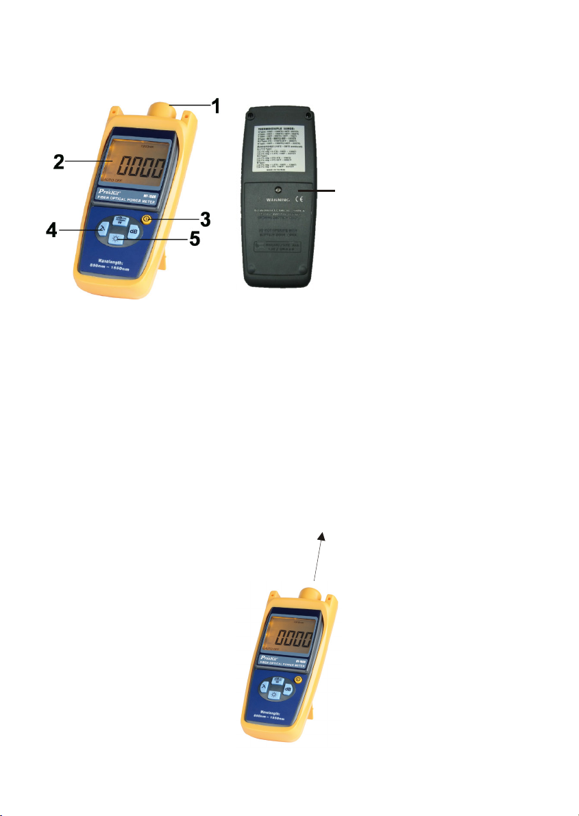
Names of Parts
1. Multi-connector (ST, FC, SC
three in one)
2. LCD.
3. Power ON/OFF button.
6
4. Function button keypad.
5. Back-light push button.
6. Battery cover
Operation
1. Press the On/Off key to turn on the Power Meter
2. Press the λ key to set wavelengths that you want to measure.
3. Connect the optical net to be measured, and then reading will be displayed on
the LCD screen, including Linear and nonlinear value.
4. Relative power measurement. Press dB key, then current power value is stored
as a reference value in dB unit.
Optic Network System
2
Page 4
Appendix:
Optical fiber loss measurement
Step 1- Optical Reference Level
Turn on optical power meter and press the λ key to select the wavelength.
Turn on optical light source and select the wavelength. Wait for 1-2 minutes
until it stabilize. Select a piece of patch cords, which is used to connect with
the light source. The patch cords must be the same fiber type as the fiber
under test. Connect the light source with the Power Meter through the
source patch cords. Power Meter will get the power measurement value.
This value should be close to the value of the light source. If it has wide
disparity, please make sure the fiber connection is clean properly else
replace jumpers.
Press the dB key; 0dB will be displayed on the screen. The tested power
values will be set to the reference value.
Step 2-Optical Loss Measurement
Keep the source patch cords connection with the light source.
Connect the Power Meter and light source (emitting source) to the optical
fiber link respectively.
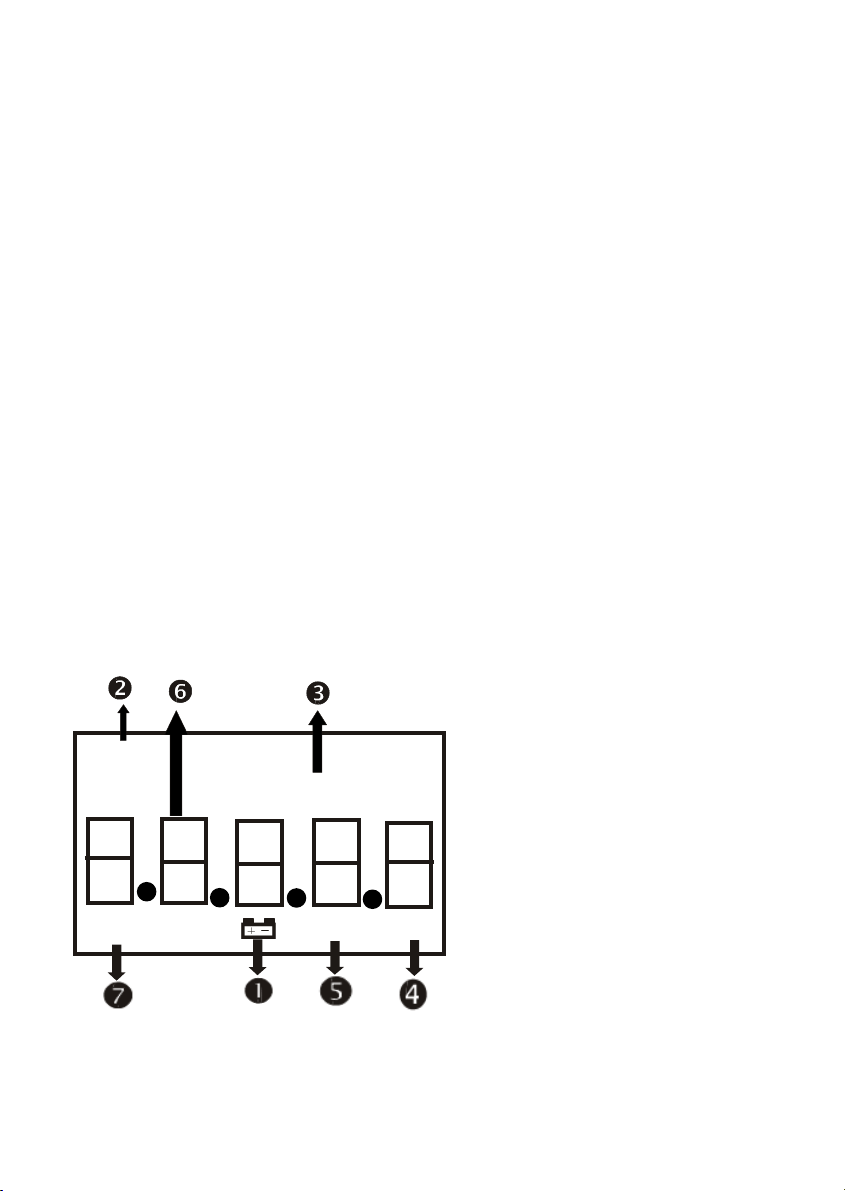
LCD Display
850nm 1300nm 1310nm
HI
dBm mWuW
1550nm
AUTO OFF
dB
nWpW
1. Low-Battery indicator: Please use alkaline battery to increase normal
operation time. When low-bat indicator is lighted, please change battery
immediately. This can assure the stability of power.
2. Wave length: Display currently measurable wavelength.
3
Page 5

3. dBm: Display currently selected unit as dBm.
4. Watt mode: When watt is selected, mW, uW, nW, pW, will be displayed
subject to the size of signal.
5. dB mode: When dB is displayed , difference between two signals can be
measured.
6. Measurement display: Display the value of signal measured.
7. Auto-power-off: To stop the instrument turning off 40 minutes after the
last key press.
Button Key Pad
1. Power button: Push the yellow POWER button. The display will come on.
Pushing POWER button again will turn the instrument off.
2. dBm/W: Push “dBm/W” to change the dBm display between linear and
log.
3. λ: Push “ λ” to Switch the operating wavelength between
850nm,1300nm,1310nm, 1550nm.
4. dB: push “dB” to display relative power, display will show dB R.
Back-light button: Push the button to turn the back-light ON or OFF.
5.
The back will automatic off after lighted 50 seconds.
4
Page 6

CARE OF
1. Always clean the mating connector tip and ferrule before mating, using
approved materials. Clean the instrument using alcohol or other non solvent
cleaning agents. Acetone or other active solvents may damage the case.
2. When not in use, keep connectors covered and away from dust. Dust and
other particles, however, can range from tenths to hundredths of microns in
diameter. Their comparative size means that they can cover a part of the end
of a fiber core, and as a result will reduce the performance of your system
3. During prolonged storage, remove batteries to eliminate the possibility of acid
leakage. Use only high quality sealed alkaline batteries.
4. Do not touch connector tips with your fingers, since body oils and dirt can
impair connector performance.
5. Do not use damaged or incompatible connectors.
6. Limit the input optical power doesn’t over measuring range.
7. The instrument is resistant to normal dust and moisture, however it is not
waterproof. If moisture does get into the instrument, dry it out carefully before
using it again.
8. This meter is a high-accuracy correct instrument, don't disassembly or
open it by yourself, otherwise the quality is not guaranteed.
9. During storage and transport, keep the instrument in its carry case to protect
against crushing, vibration, dust and moisture.
10. Where possible, keep instrument away from strong sunlight.
YOUR INSTRUMENT
Procedure for Stubborn Dirt
1. Moisten a new cotton swab with alcohol.
2. Clean the interface by rubbing the cotton swab over the surface using a
small circular movement.
3. Take a new, dry soft tissue and remove the alcohol, dissolved sediment and
dust, by rubbing gently over the surface using a small circular movement.
4. Blow away any remaining lint with compressed air.
5
Page 7

MT-7600 光纖功率表
操作說明書
序言
感謝您購買此光纖功率錶. 在操作此光纖功率錶前請先閱讀使用說明書,
以確保您能安全及正確地操作此光纖功率錶.
規格
1. 使用 InGaAs 光二極體並具有既 寬與平的反應曲線.
2. 測量波長: 850nm , 1300nm , 1310nm, 1550nm.
3. 測量範圍: +3dBm ~ -55dBm , 2mW ~ 4nW.
4. 解析度: 0.01.
5. 精度:0.3dBm.
6. 連接器: ST+SC+FC 三合一.
7. 過載指示.
8. 低電力指示.
9. 自動關機.
10. 背光功能.
11. 電源︰ 4 顆 1.5V 電池 (不含)
12. 操作/儲存溫度(濕度)︰-0 ~ 50°C / -20 ~ 60°C (0~80%RH)
13. 配件︰說明書,保存盒, SC 跳接線 1 條, LC 轉接頭(選配)
14. 尺寸︰185 x 84 x 42mm
15. 重量︰ 420g
6
Page 8

各部名稱
1. 光纖功率錶的連接器.
2. 螢幕.
3. 光纖功率錶的電源開關.
4. 光纖功率錶的功能鍵.
5. 背光的按鍵.
6. 電池蓋.
操作
6
標準光源
一般光纖網路量測
1. 連接光纖網路線到光纖功率表
2. 按下電源鍵控制電源的開與關.
3. λ:選擇適合的波長,重複按可 850,1300,1310,1550nm 跳動.選
擇與光纖網路相同的波長
4. 依需求選
5. 按 db 鍵即可自動計算出 dB 值
擇 dBm 或是 W 單位
7
Page 9

***比較標
準光源並且計算光纖功率的損失
1. 選擇一條跳接線,連接光纖功率錶及標準光源.
2. 讀出光纖功率錶的值定義為P1.
3. 使用光纖跳接線連接成光纖網路.
4. 在另一端,使用光纖功率錶連接光源錶,定義值為P2.
PLoss = P2 - P1
P2
L
CD 配置說明
標準光源
有接點光纖網路線
8
Page 10

1. 低電力符
號:當此符號產生時,1.5V 電池請立即更
換.以
維持測量的準確性.
2. 波長:螢幕會顯示測量的波長.
3. dBm:螢幕顯示的單位是:dBm.
4. Watt模式:當您使用watt模式時,將有mW, uW, nW, pW供選擇.
5. dB模式:當您選擇dB模式時,您可以測量兩個不同的信號.
6. 測量顯示:螢幕可以顯示測量值.
7. 自動關機:當自動關機顯示時,意即在沒按下任何按鍵情況下,主機
8. 將在 40分鐘後自動關
機.
按鍵配置說明
1. 光纖功率錶的電源鍵:按下電源鍵可控制光纖功率錶的開與關.
2. dBm/Watt:按下此按鍵可切換dBm或Watt.
3. λ此按鍵可選擇波長:850nm,1300nm, 1310nm, 1550nm.
4. dB可測量兩個不同的信號.
5.
按下此按可控制背光的開與關.在不關閉背光的情況下,背光光源可持
續點亮約50秒後即會自動關閉背光功能.
9
Page 11

保養及
1. 使用拭鏡紙及酒精清潔連接器,並使用空氣球吹
安全須知
面.
乾.不
可使灰塵沾在連接器上
2. 當主機不使用時,請將主機擦拭後放入手提箱內,假如有灰塵沾在連接器內,將
會增加測量的不確定性.
3. 假如您長時間不使用主
機.請
記住將電池取出以避免發生可能的危險.
注意事項
1. 連接器請勿重壓或碰撞.也不能接觸化學藥品或沾上灰塵, 連接器表面請用拭淨
紙擦拭.
1. 請使用鹼性電池以增加使用的時間.當低電力符號顯示時,請立即更換電池.
2. 假如使用外部的電源時,請選擇正確規格的整流器以避免發生危險.
3. 請勿將主機置於不允許的環境下操作.
4. 本機為一高精密的測量儀器,請不要自行打開它,否則品質無法確保.
10
Page 12

2011 Prokit’s Industries Co., LTD. All rights reserved 2011001(T)
©
11
 Loading...